Embed Size (px)
Citation preview

TRAFFIC PROTECTION IN TRANSPORT NETWORKS
Alberto BellatoCTO Technology and architectureOptical Networks Division ALCATEL Vimercate
A. Bellato – CTO T&A Team - OND 2
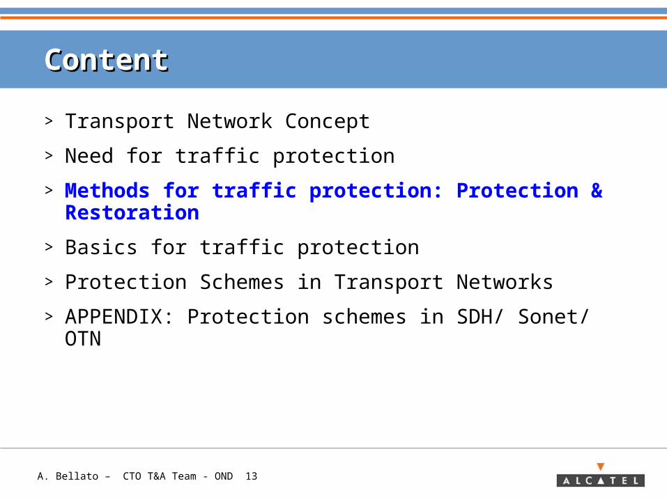
ContentContent
> Transport Network Concept
> Need for traffic protection
> Methods for traffic protection: Protection & Restoration
> Basics for traffic protection
> Protection Schemes in Transport Networks
> APPENDIX: Protection schemes in SDH/ Sonet/ OTN
A. Bellato – CTO T&A Team - OND 3
ContentContent
> Transport Network Concept
> Need for traffic protection
> Methods for traffic protection: Protection & Restoration
> Basics for traffic protection
> Protection Schemes in Transport Networks
> APPENDIX: Protection schemes in SDH/ Sonet/ OTN
A. Bellato – CTO T&A Team - OND 4
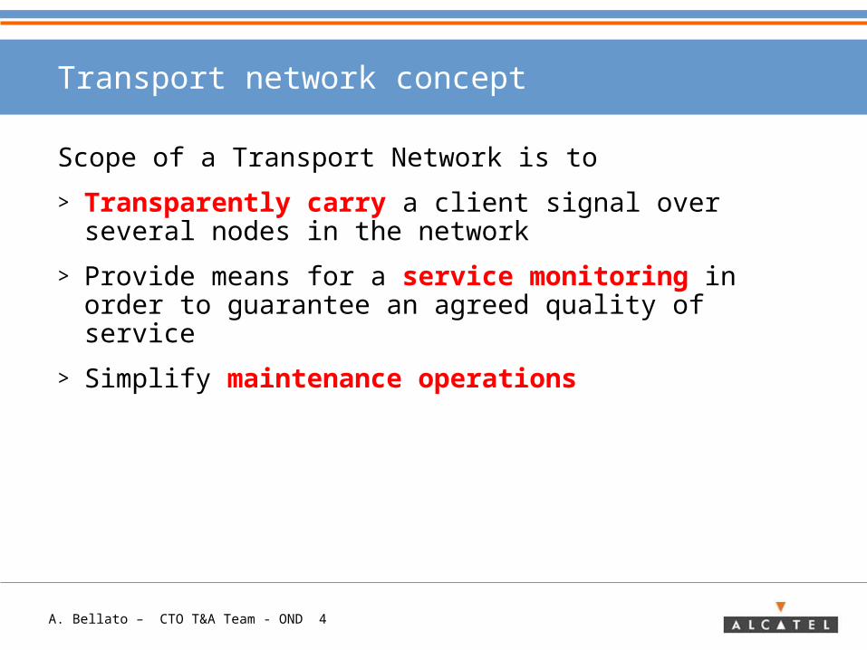
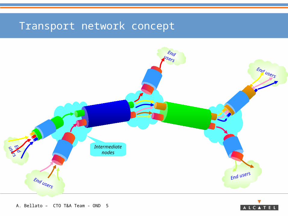
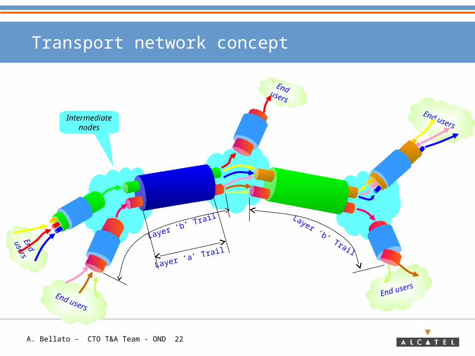
Transport network concept
Scope of a Transport Network is to
> Transparently carry a client signal over several nodes in the network
> Provide means for a service monitoring in order to guarantee an agreed quality of service
> Simplify maintenance operations
A. Bellato – CTO T&A Team - OND 5
End users
End
users
End users
End
users
End users
Transport network concept
Intermediate nodes
A. Bellato – CTO T&A Team - OND 6
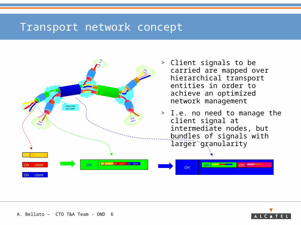
Transport network concept
> Client signals to be carried are mapped over hierarchical transport entities in order to achieve an optimized network management
> I.e. no need to manage the client signal at intermediate nodes, but bundles of signals with larger granularity
End users
End
users
End users
End users
End
users
Intermediate
nodes
client
client
client
OH
OH
OH
OH clientOH clientOH clientOH OHOH
OH
A. Bellato – CTO T&A Team - OND 7
ContentContent
> Transport Network Concept
> Need for traffic protection
> Methods for traffic protection: Protection & Restoration
> Basics for traffic protection
> Protection Schemes in Transport Networks
> APPENDIX: Protection schemes in SDH/ Sonet/ OTN
A. Bellato – CTO T&A Team - OND 8
Need for traffic protection
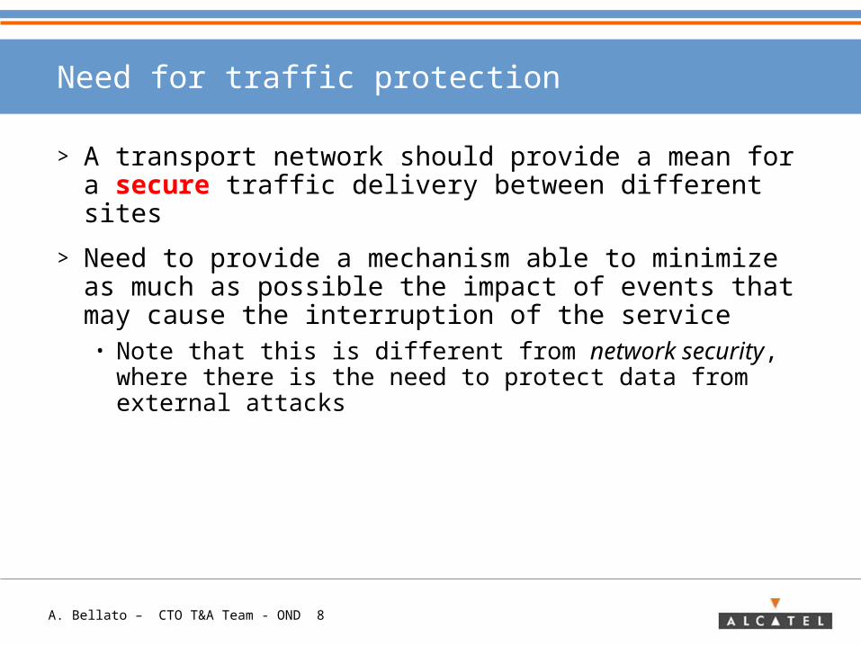
> A transport network should provide a mean for a secure traffic delivery between different sites
> Need to provide a mechanism able to minimize as much as possible the impact of events that may cause the interruption of the service• Note that this is different from network security, where
there is the need to protect data from external attacks
A. Bellato – CTO T&A Team - OND 9
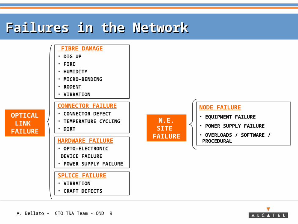
Failures in the NetworkFailures in the Network
NODE FAILURE
• EQUIPMENT FAILURE
• POWER SUPPLY FAILURE
• OVERLOADS / SOFTWARE / PROCEDURAL
FIBRE DAMAGE• DIG UP• FIRE• HUMIDITY• MICRO-BENDING • RODENT• VIBRATION
CONNECTOR FAILURE • CONNECTOR DEFECT• TEMPERATURE CYCLING• DIRTHARDWARE FAILURE • OPTO-ELECTRONIC
DEVICE FAILURE• POWER SUPPLY FAILURE
SPLICE FAILURE • VIBRATION• CRAFT DEFECTS
OPTICAL LINK
FAILURE
N.E. SITE FAILURE
A. Bellato – CTO T&A Team - OND 10
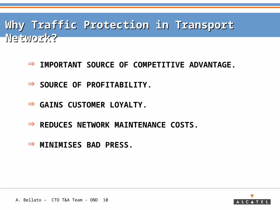
Why Traffic Protection in Transport Network?Why Traffic Protection in Transport Network?
IMPORTANT SOURCE OF COMPETITIVE ADVANTAGE.
SOURCE OF PROFITABILITY.
GAINS CUSTOMER LOYALTY.
REDUCES NETWORK MAINTENANCE COSTS.
MINIMISES BAD PRESS.
A. Bellato – CTO T&A Team - OND 11
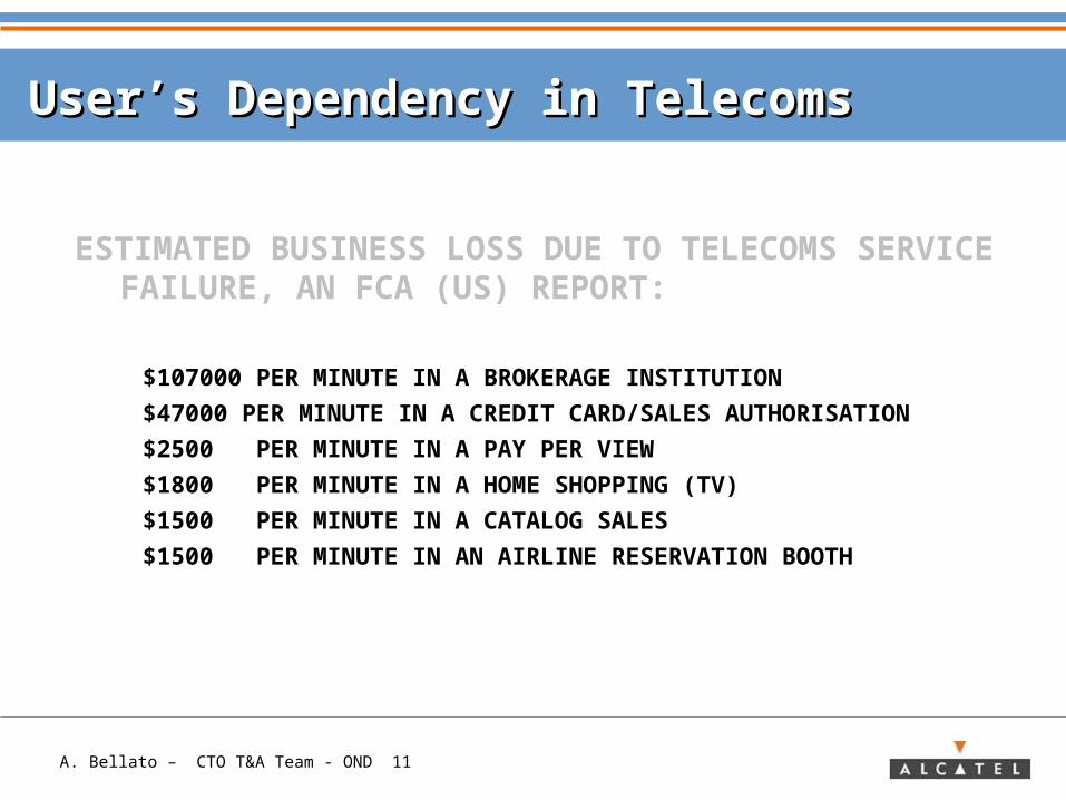
ESTIMATED BUSINESS LOSS DUE TO TELECOMS SERVICE FAILURE, AN FCA (US) REPORT:
$107000 PER MINUTE IN A BROKERAGE INSTITUTION
$47000 PER MINUTE IN A CREDIT CARD/SALES AUTHORISATION
$2500 PER MINUTE IN A PAY PER VIEW
$1800 PER MINUTE IN A HOME SHOPPING (TV)
$1500 PER MINUTE IN A CATALOG SALES
$1500 PER MINUTE IN AN AIRLINE RESERVATION BOOTH
User’s Dependency in TelecomsUser’s Dependency in Telecoms
A. Bellato – CTO T&A Team - OND 12
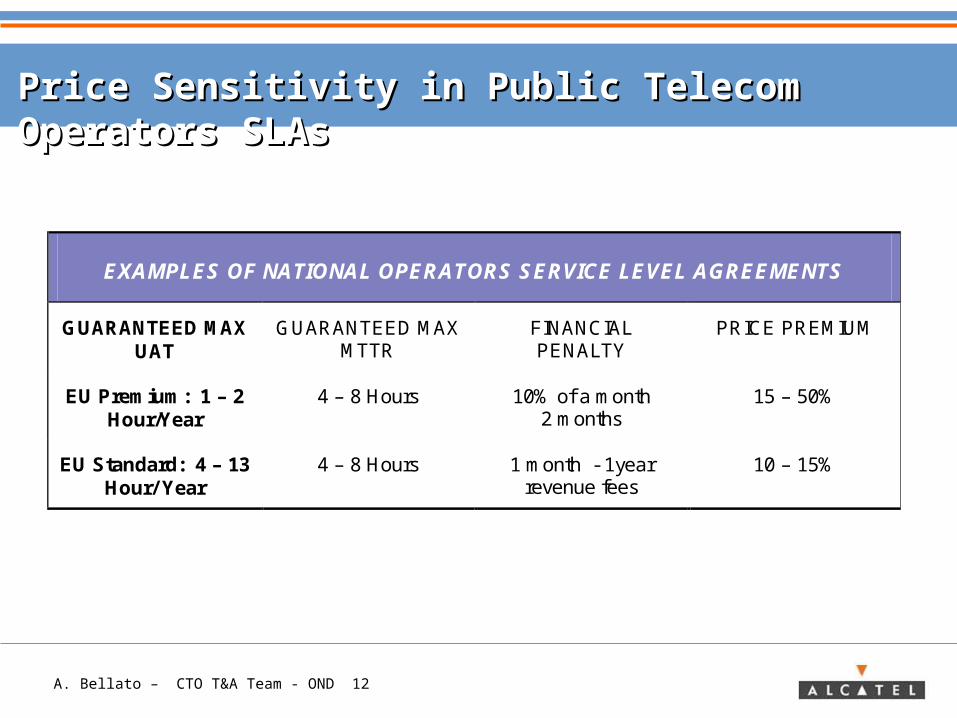
Price Sensitivity in Public Telecom Operators SLAsPrice Sensitivity in Public Telecom Operators SLAs
EXAMPLES OF NATIONAL OPERATORS SERVICE LEVEL AGREEMENTS
GUARANTEED MAX UAT
GUARANTEED MAX MTTR
FINANCIAL PENALTY
PRICE PREMIUM
EU Premium: 1 – 2 Hour/Year
4 – 8 Hours 10% of a month 2 months
15 – 50%
EU Standard: 4 – 13 Hour/ Year
4 – 8 Hours 1 month - 1year revenue fees
10 – 15%
A. Bellato – CTO T&A Team - OND 13
ContentContent
> Transport Network Concept
> Need for traffic protection
> Methods for traffic protection: Protection & Restoration
> Basics for traffic protection
> Protection Schemes in Transport Networks
> APPENDIX: Protection schemes in SDH/ Sonet/ OTN
A. Bellato – CTO T&A Team - OND 14
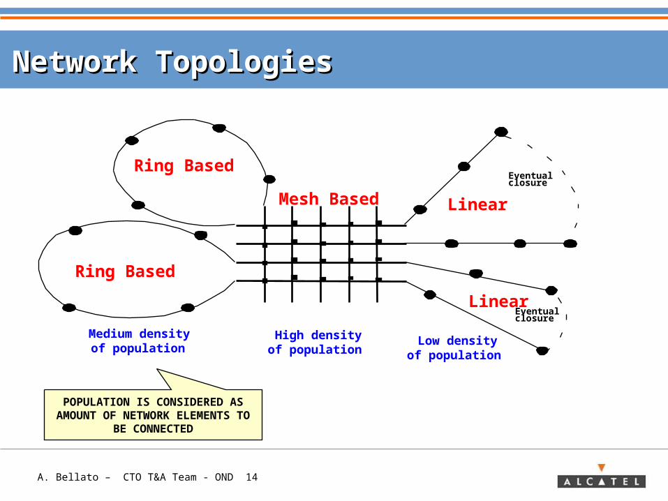
Network TopologiesNetwork Topologies
Medium densityof population
High densityof population
Low densityof population
Ring Based
Ring Based
Mesh Based Linear
Eventualclosure
Eventualclosure
Linear
POPULATION IS CONSIDERED AS AMOUNT OF NETWORK
ELEMENTS TO BE CONNECTED
A. Bellato – CTO T&A Team - OND 15
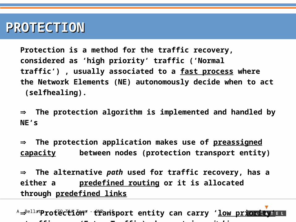
Protection is a method for the traffic recovery, considered as ‘high priority‘ traffic (‘Normal traffic‘) , usually associated to a fast process where the Network Elements (NE) autonomously decide when to act (selfhealing).
The protection algorithm is implemented and handled by NE‘s
The protection application makes use of preassigned capacity between nodes (protection transport entity)
The alternative path used for traffic recovery, has a either a predefined routing or it is allocated through predefined links
‘Protection‘ transport entity can carry ‘low priority‘ traffic (Extra Traffic) when not in switching condition
PROTECTIONPROTECTION
A. Bellato – CTO T&A Team - OND 16
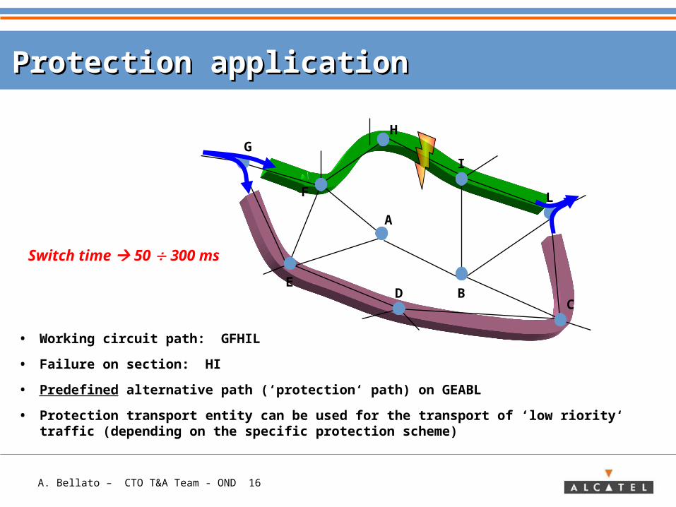
• Working circuit path: GFHIL
• Failure on section: HI
• Predefined alternative path (‘protection‘ path) on GEABL
• Protection transport entity can be used for the transport of ‘low riority‘ traffic (depending on the specific protection scheme)
G
F
E
A
H
I
L
D BC
Protection applicationProtection application
Switch time 50 300 ms
A. Bellato – CTO T&A Team - OND 17
Restoration is a method for the traffic recovery, usually associated to a slower process, where the switching decision is taken by a Network Management System (NMS) which can be either centralized or distributed through the network.
The restoration application makes use of any capacity available between nodes, depending on failure
scenario and on traffic matrix
The restored path doesn't have a ‘unique‘ predefined routing.
RESTORATIONRESTORATION
A. Bellato – CTO T&A Team - OND 18
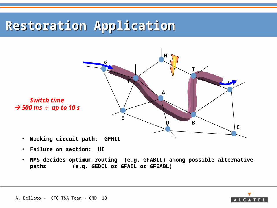
Switch time 500 ms up to 10 s
• Working circuit path: GFHIL
• Failure on section: HI
• NMS decides optimum routing (e.g. GFABIL) among possible alternative paths (e.g. GEDCL or GFAIL or GFEABL)
G
F
E
A
H
I
L
D BC
Restoration ApplicationRestoration Application
A. Bellato – CTO T&A Team - OND 19
Network TopologiesNetwork Topologies
PROTECTION
PROTECTION
RESTORATION
PROTECTION
PROTECTION
Medium densityof population
High densityof population
Low densityof population
Ring Based
Ring Based
Mesh Based Linear
Eventualclosure
Eventualclosure
LinearPROTECTIO
N
A. Bellato – CTO T&A Team - OND 20
ContentContent
> Transport Network Concept
> Need for traffic protection
> Methods for traffic protection: Protection & Restoration
> Basics for traffic protection• Definitions• Switching Criteria• Protection Architectures
> Protection Schemes in Transport Networks
> APPENDIX: Protection schemes in SDH/ Sonet/ OTN
A. Bellato – CTO T&A Team - OND 21
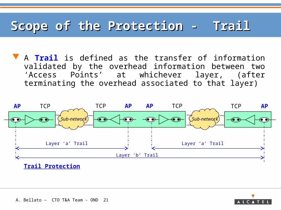
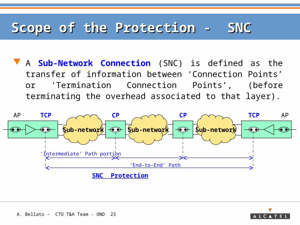
A Trail is defined as the transfer of information validated by the overhead information between two ‘Access Points’ at whichever layer, (after terminating the overhead associated to that layer)
Scope of the Protection - Trail Scope of the Protection - Trail
Trail Protection
Sub-network
TCPAP TCP AP
Layer ‘a’ Trail
TCP AP TCPAP
Sub-network
Layer ‘a’ Trail
Layer ‘b’ Trail
A. Bellato – CTO T&A Team - OND 22
End users
End
users
End users
End
users
End users
Transport network concept
Intermediate nodes
Layer ‘b’ Trail Layer ‘b’ Trail
Layer ‘a’ Trail
A. Bellato – CTO T&A Team - OND 23
A Sub-Network Connection (SNC) is defined as the transfer of information between ‘Connection Points’ or ‘Termination Connection Points’, (before terminating the overhead associated to that layer).
Scope of the Protection - SNC Scope of the Protection - SNC
SNC Protection
Sub-networkSub-network
TCPAP CP CP
Sub-network
TCP AP
‘End-to-End’ Path
‘Intermediate’ Path portion
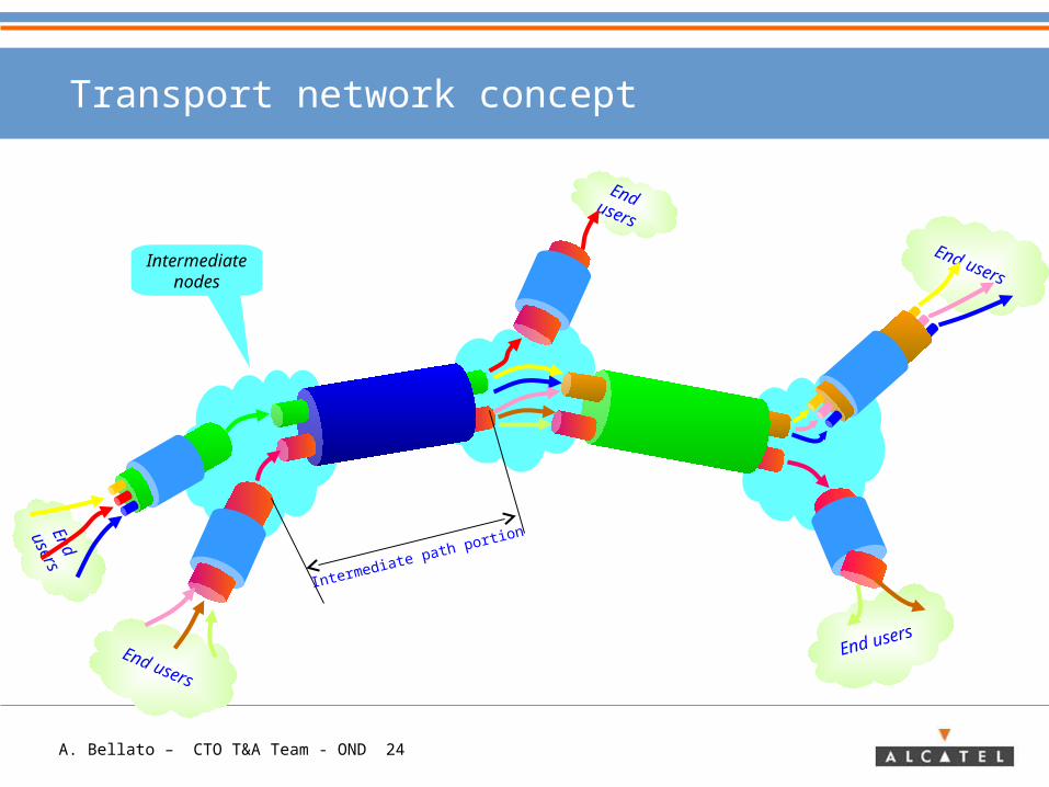
A. Bellato – CTO T&A Team - OND 24
End users
End
users
End users
End
users
End users
Transport network concept
Intermediate nodes
Intermediate path portion
A. Bellato – CTO T&A Team - OND 25
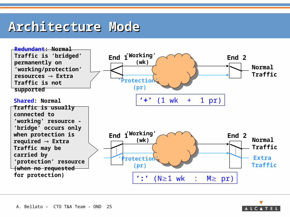
Architecture ModeArchitecture Mode
Normal Traffic
‘+’ (1 wk + 1 pr)
End 1 End 2Redundant: Normal Traffic is ‘bridged’ permanently on ‘working/protection’ resources Extra Traffic is not supported
Shared: Normal Traffic is usually connected to ‘working’ resource - ‘bridge’ occurs only when protection is required Extra Traffic may be carried by ‘protection’ resource (when no requested for protection)
‘Working’ (wk)
‘Protection’ (pr)
Normal Traffic
‘:’ (N1 wk : M pr)
End 1 End 2‘Working’ (wk)
‘Protection’ (pr)
Extra Traffic
A. Bellato – CTO T&A Team - OND 26
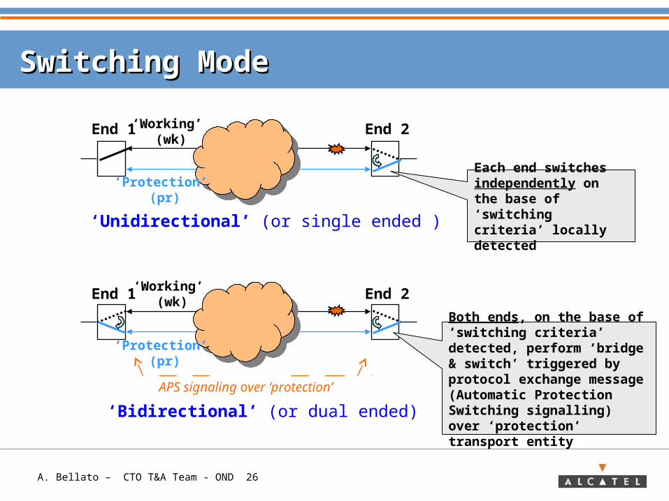
Switching ModeSwitching Mode
‘Unidirectional’ (or single ended )
‘Bidirectional’ (or dual ended)
End 1 End 2
End 1 End 2
Each end switches independently on the base of ‘switching criteria’ locally detected
Both ends, on the base of ‘switching criteria’ detected, perform ‘bridge & switch’ triggered by protocol exchange message (Automatic Protection Switching signalling) over ‘protection’ transport entity
APS signaling over ‘protection’
‘Working’ (wk)
‘Protection’ (pr)
‘Protection’ (pr)
‘Working’ (wk)
A. Bellato – CTO T&A Team - OND 27
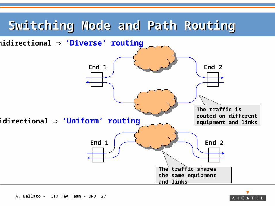
Switching Mode and Path RoutingSwitching Mode and Path Routing
Bidirectional ‘Uniform’ routing
The traffic shares the same equipment and links
End 1 End 2
End 1 End 2
Unidirectional ‘Diverse’ routing
The traffic is routed on different equipment and links
A. Bellato – CTO T&A Team - OND 28
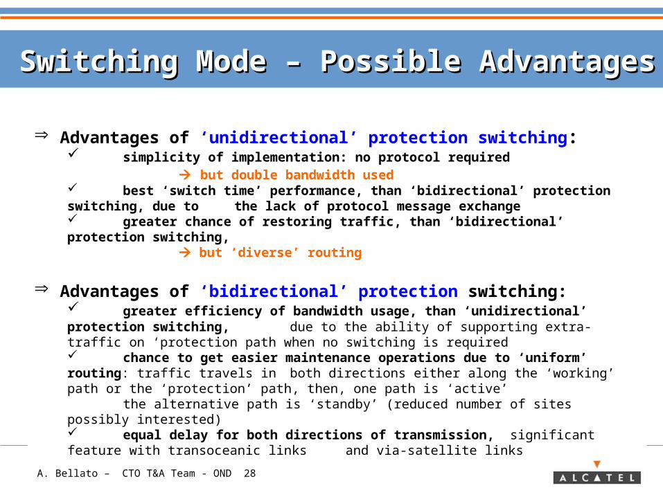
Switching Mode – Possible AdvantagesSwitching Mode – Possible Advantages
Advantages of ‘unidirectional’ protection switching: simplicity of implementation: no protocol required
but double bandwidth used best ‘switch time’ performance, than ‘bidirectional’ protection switching, due to the lack of protocol message exchange greater chance of restoring traffic, than ‘bidirectional’ protection switching,
but ‘diverse’ routing
Advantages of ‘bidirectional’ protection switching: greater efficiency of bandwidth usage, than ‘unidirectional’ protection switching, due to the ability of supporting extra-traffic on ‘protection path when no switching is required chance to get easier maintenance operations due to ‘uniform’ routing: traffic travels in both directions either along the ‘working’ path or the ‘protection’ path, then, one path is ‘active’
the alternative path is ‘standby’ (reduced number of sites possibly interested)
equal delay for both directions of transmission, significant feature with transoceanic links and via-satellite links
A. Bellato – CTO T&A Team - OND 29
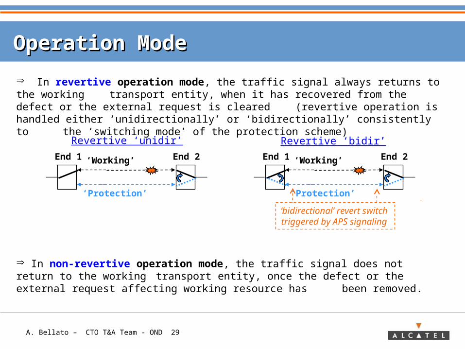
Operation ModeOperation Mode
In revertive operation mode, the traffic signal always returns to the working transport entity, when it has recovered from the defect or the external request
is cleared (revertive operation is handled either ‘unidirectionally’ or ‘bidirectionally’ consistently to the ‘switching mode’ of the protection scheme)
Revertive ‘unidir’
End 1 End 2‘Working’
‘Protection’
In non‑revertive operation mode, the traffic signal does not return to the working transport entity, once the defect or the external request affecting working resource has been removed.
Revertive ‘bidir’
End 1 End 2‘Working’
‘Protection’
‘bidirectional’ revert switch triggered by APS signaling
A. Bellato – CTO T&A Team - OND 30
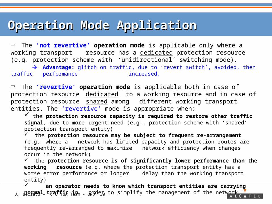
Operation Mode ApplicationOperation Mode Application
The ‘not revertive’ operation mode is applicable only where a working transport resource has a dedicated protection resource (e.g. protection scheme with ‘unidirectional’ switching mode).
Advantage: glitch on traffic, due to ‘revert switch’, avoided, then traffic performance increased.
The ‘revertive’ operation mode is applicable both in case of protection resource dedicated to a working resource and in case of protection resourceshared among different working transport entities. The ‘revertive’ mode is appropriate when:
the protection resource capacity is required to restore other traffic signal, due to more urgent need (e.g., protection scheme with ‘shared’ protection transport entity) the protection resource may be subject to frequent re-arrangement (e.g. where a network has limited capacity and protection routes are frequently re-arranged to maximize network efficiency when changes occur in the network) the protection resource is of significantly lower performance than the working resource (e.g. where the protection transport entity has a worse error performance or longer delay than the working transport entity) an operator needs to know which transport entities are carrying normal traffic in order to simplify the management of the network
A. Bellato – CTO T&A Team - OND 31
ContentContent
> Transport Network Concept
> Need for traffic protection
> Methods for traffic protection: Protection & Restoration
> Basics for traffic protection• Definitions• Switching Criteria• Protection Architectures
> Protection Schemes in Transport Networks
> APPENDIX: Protection schemes in SDH/ Sonet/ OTN
A. Bellato – CTO T&A Team - OND 32
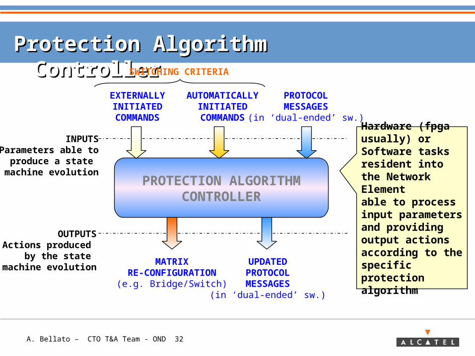
Protection Algorithm ControllerProtection Algorithm Controller
PROTECTION ALGORITHMCONTROLLER
INPUTSParameters able to
produce a state machine evolution
OUTPUTSActions produced
by the state machine evolution
EXTERNALLYINITIATED
COMMANDS
AUTOMATICALLYINITIATED
COMMANDS
PROTOCOLMESSAGES
(in ‘dual-ended’ sw.)
MATRIXRE-CONFIGURATION
(e.g. Bridge/Switch)
UPDATEDPROTOCOLMESSAGES
(in ‘dual-ended’ sw.)
Hardware (fpga usually) or Software tasks resident into the Network Elementable to process input parameters and providing output actions according to the specific protection algorithm
SWITCHING CRITERIA
A. Bellato – CTO T&A Team - OND 33
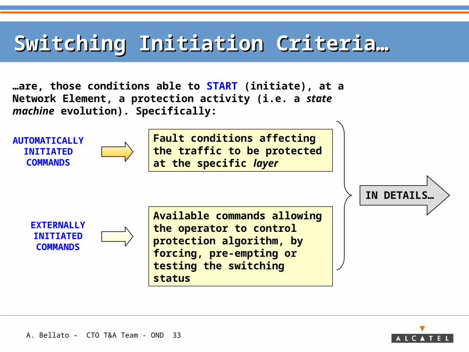
Switching Initiation Criteria…Switching Initiation Criteria…
AUTOMATICALLYINITIATED
COMMANDS
EXTERNALLYINITIATED
COMMANDS
Fault conditions affecting the traffic to be protected at the specific layer
Available commands allowing the operator to control protection algorithm, by forcing, pre-empting or testing the switching status
…are, those conditions able to START (initiate), at a Network Element, a protection activity (i.e. a state machine evolution). Specifically:
IN DETAILS…
A. Bellato – CTO T&A Team - OND 34
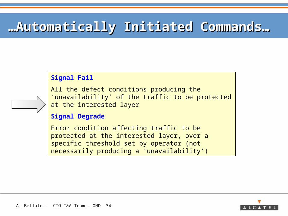
……Automatically Initiated Commands…Automatically Initiated Commands…
Signal Fail
All the defect conditions producing the ‘unavailability’ of the traffic to be protected at the interested layer
Signal Degrade
Error condition affecting traffic to be protected at the interested layer, over a specific threshold set by operator (not necessarily producing a ‘unavailability’)
A. Bellato – CTO T&A Team - OND 35
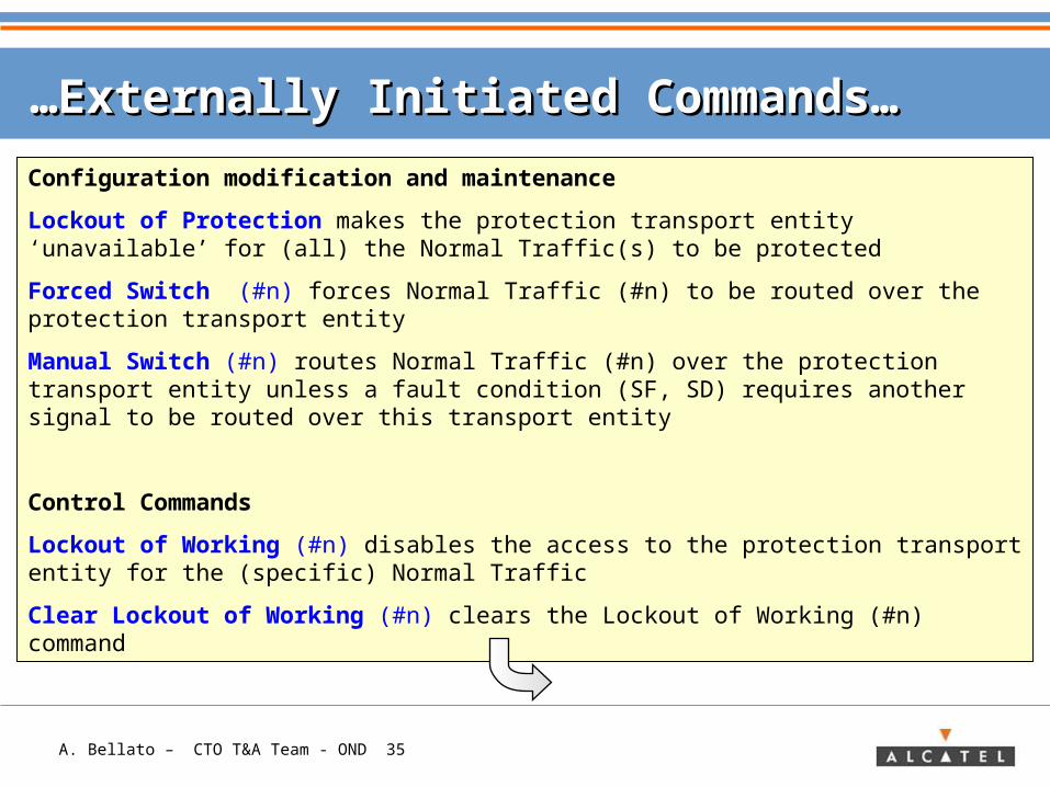
……Externally Initiated Commands…Externally Initiated Commands…
Configuration modification and maintenance
Lockout of Protection makes the protection transport entity ‘unavailable’ for (all) the Normal Traffic(s) to be protected
Forced Switch (#n) forces Normal Traffic (#n) to be routed over the protection transport entity
Manual Switch (#n) routes Normal Traffic (#n) over the protection transport entity unless a fault condition (SF, SD) requires another signal to be routed over this transport entity
Control Commands
Lockout of Working (#n) disables the access to the protection transport entity for the (specific) Normal Traffic
Clear Lockout of Working (#n) clears the Lockout of Working (#n) command
A. Bellato – CTO T&A Team - OND 36
……Externally Initiated Commands…Externally Initiated Commands…
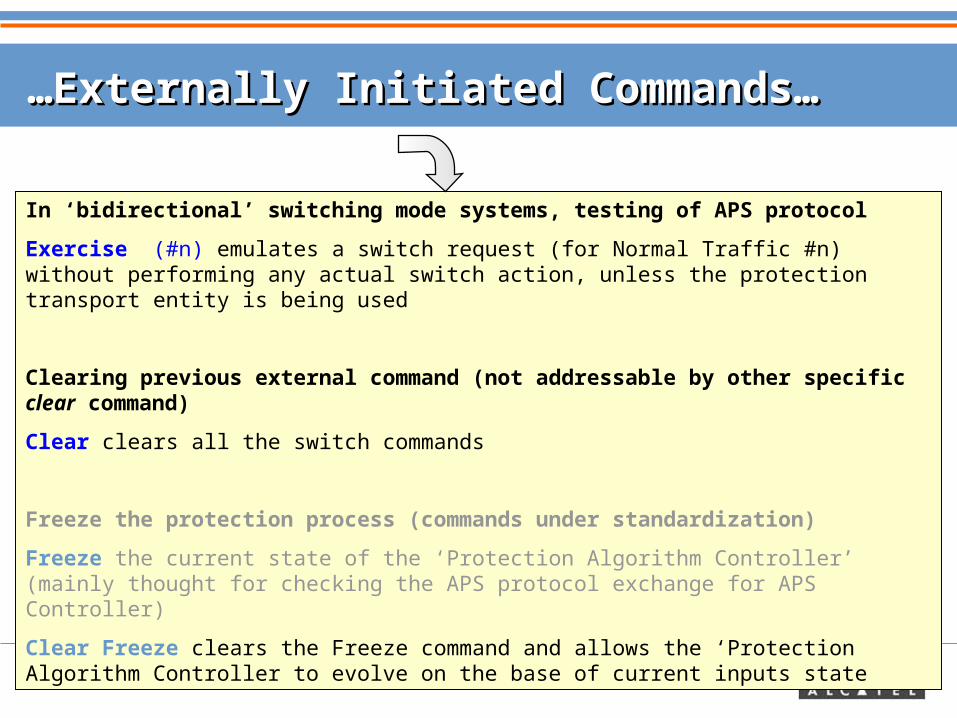
In ‘bidirectional’ switching mode systems, testing of APS protocol
Exercise (#n) emulates a switch request (for Normal Traffic #n) without performing any actual switch action, unless the protection transport entity is being used
Clearing previous external command (not addressable by other specific clear command)
Clear clears all the switch commands
Freeze the protection process (commands under standardization)
Freeze the current state of the ‘Protection Algorithm Controller’ (mainly thought for checking the APS protocol exchange for APS Controller)
Clear Freeze clears the Freeze command and allows the ‘Protection Algorithm Controller to evolve on the base of current inputs state
A. Bellato – CTO T&A Team - OND 37
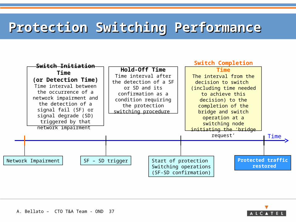
Hold-Off TimeTime interval after the detection of a SF or SD
and its confirmation as a condition requiring the protection switching
procedure
Protection Switching PerformanceProtection Switching Performance
Switch Completion Time
The interval from the decision to switch
(including time needed to achieve this decision) to the
completion of the bridge and switch operation at a
switching node initiating the ‘bridge request’
Switch Initiation Time
(or Detection Time)Time interval between the occurrence of a network
impairment and the detection of a signal fail
(SF) or signal degrade (SD) triggered by that network
impairment
Network Impairment SF – SD trigger Start of protection Switching operations(SF-SD confirmation)
Protected traffic restored
Time
A. Bellato – CTO T&A Team - OND 38
ContentContent
> Transport Network Concept
> Need for traffic protection
> Methods for traffic protection: Protection & Restoration
> Basics for traffic protection• Definitions• Switching Criteria• Protection Architectures
> Protection Schemes in Transport Networks
> APPENDIX: Protection schemes in SDH/ Sonet/ OTN
A. Bellato – CTO T&A Team - OND 39
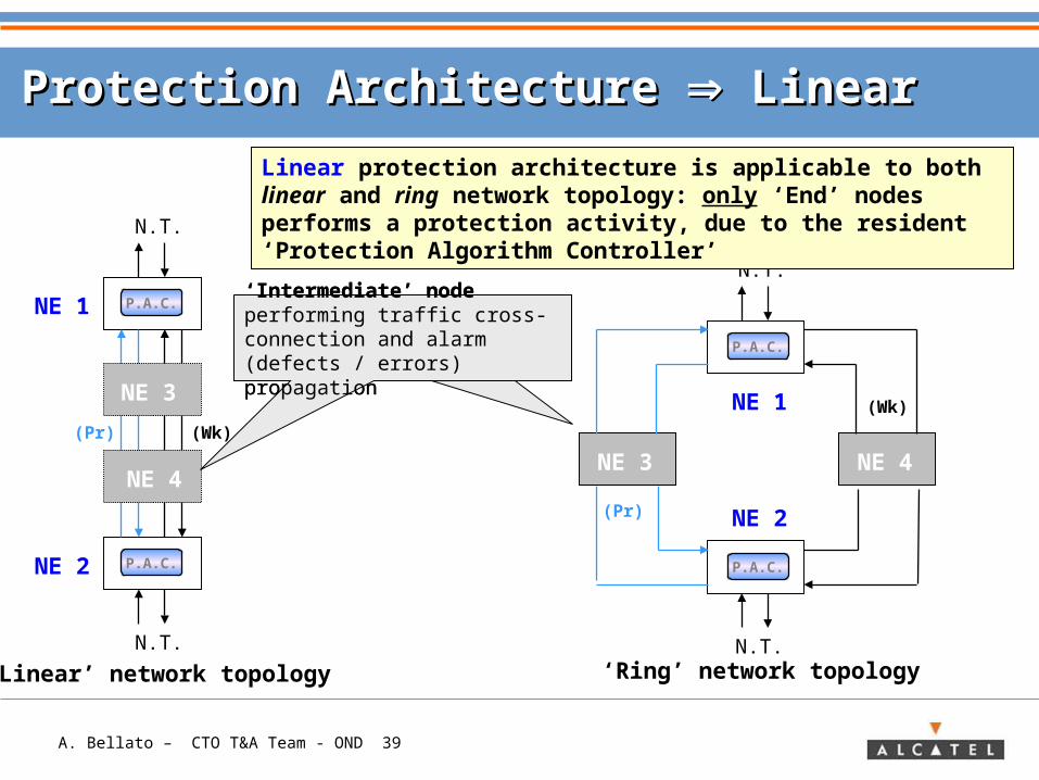
Protection Architecture Protection Architecture Linear Linear
N.T.
NE 1
NE 2
NE 3
N.T.
NE 1
NE 2
NE 4
N.T.N.T.
NE 3
NE 4
‘Linear’ network topology ‘Ring’ network topology
(Wk)
(Wk)
(Pr)
(Pr)
P.A.C.
P.A.C.
P.A.C.
P.A.C.
Linear protection architecture is applicable to both linear and ring network topology: only ‘End’ nodes performs a protection activity, due to the resident ‘Protection Algorithm Controller’
‘Intermediate’ node performing traffic cross-connection and alarm (defects / errors) propagation
‘Intermediate’ node performing traffic cross-connection and alarm (defects / errors) propagation
A. Bellato – CTO T&A Team - OND 40
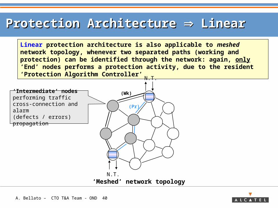
Protection Architecture Protection Architecture Linear Linear
N.T.‘Meshed’ network topology
Linear protection architecture is also applicable to meshed network topology, whenever two separated paths (working and protection) can be identified through the network: again, only ‘End’ nodes performs a protection activity, due to the resident ‘Protection Algorithm Controller’
‘Intermediate’ nodes performing traffic cross-connection and alarm (defects / errors) propagation
N.T.
(Wk)
(Pr)
A. Bellato – CTO T&A Team - OND 41
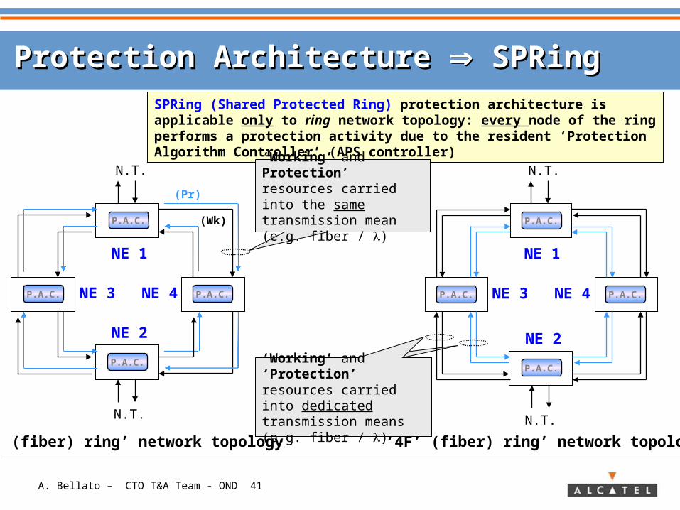
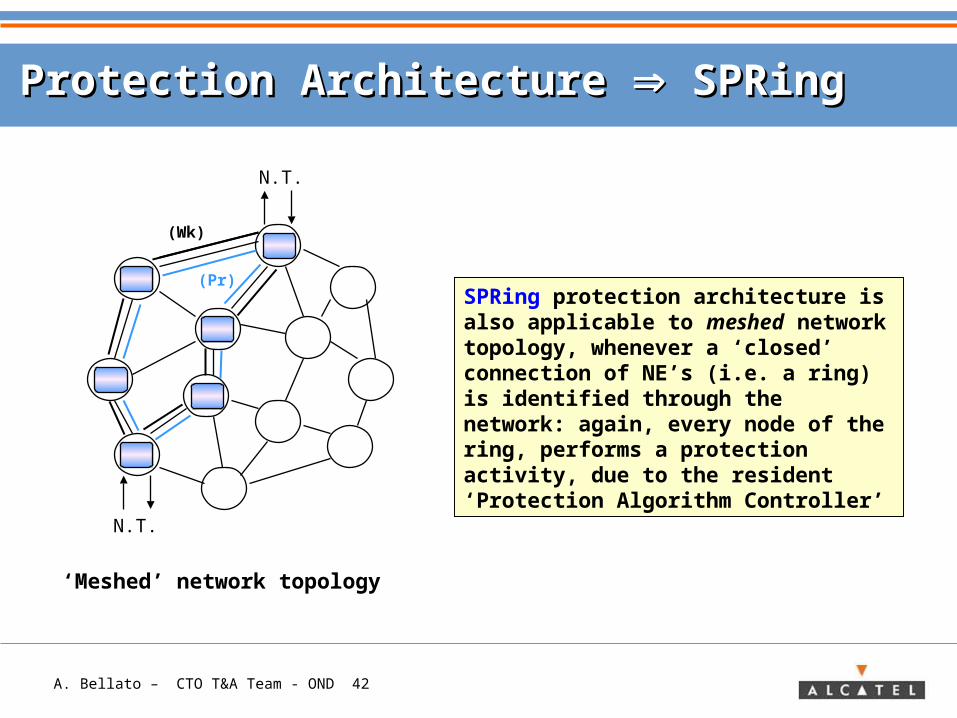
Protection Architecture Protection Architecture SPRing SPRing
N.T.
NE 1
NE 2
NE 4
N.T.
P.A.C.
P.A.C. P.A.C.
P.A.C.
SPRing (Shared Protected Ring) protection architecture is applicable only to ring network topology: every node of the ring performs a protection activity due to the resident ‘Protection Algorithm Controller’ (APS controller)
‘2F’ (fiber) ring’ network topology
NE 3
N.T.
NE 1
NE 2
NE 4
N.T.
P.A.C.
P.A.C. P.A.C.
P.A.C.
NE 3
‘4F’ (fiber) ring’ network topology
‘Working’ and Protection’ resources carried into the same transmission mean (e.g. fiber / )(Wk)
(Pr)
‘Working’ and ‘Protection’ resources carried into dedicated transmission means (e.g. fiber / )
A. Bellato – CTO T&A Team - OND 42
Protection Architecture Protection Architecture SPRing SPRing
SPRing protection architecture is also applicable to meshed network topology, whenever a ‘closed’ connection of NE’s (i.e. a ring) is identified through the network: again, every node of the ring, performs a protection activity, due to the resident ‘Protection Algorithm Controller’
N.T.
‘Meshed’ network topology
N.T.
(Wk)
(Pr)
A. Bellato – CTO T&A Team - OND 43
ContentContent
> Transport Network Concept
> Need for traffic protection
> Methods for traffic protection: Protection & Restoration
> Basics for traffic protection
> Protection Schemes in Transport Networks• Linear• Ring
> APPENDIX: Protection schemes in SDH/ Sonet/ OTN
A. Bellato – CTO T&A Team - OND 44
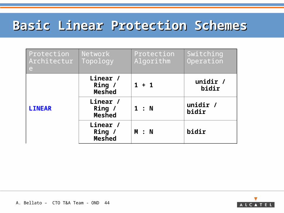
Basic Linear Protection SchemesBasic Linear Protection Schemes
Protection Architecture
Network Topology
Protection Algorithm
Switching Operation
LINEAR
Linear / Ring / Meshed 1 + 1 unidir / bidir
Linear / Ring / Meshed 1 : N unidir / bidir
Linear / Ring / Meshed M : N bidir
A. Bellato – CTO T&A Team - OND 45
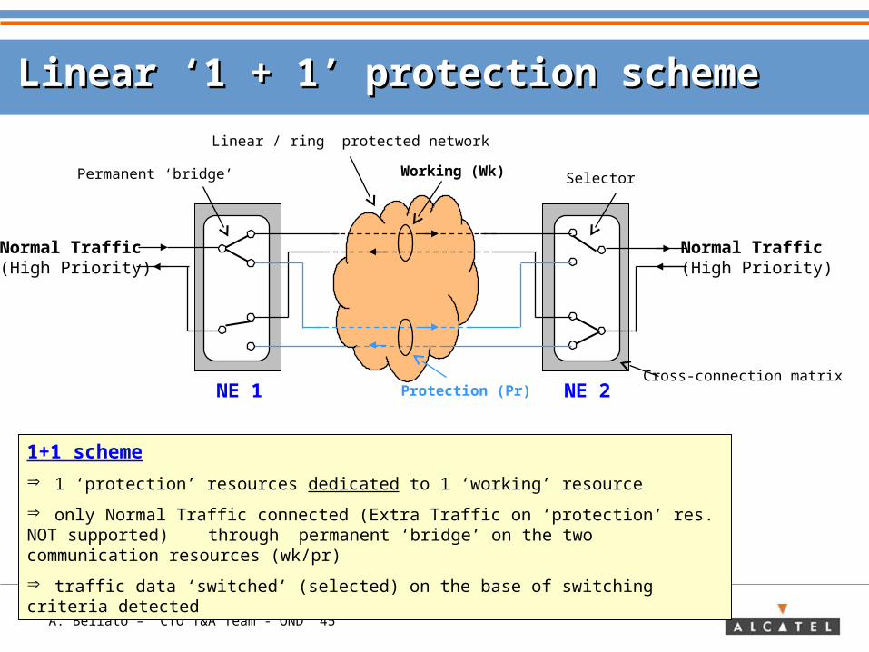
Linear ‘1 + 1’ protection schemeLinear ‘1 + 1’ protection scheme
NE 1 NE 2Cross-connection matrix
Linear / ring protected network
Working (Wk)
Protection (Pr)
Normal Traffic(High Priority)
Normal Traffic(High Priority)
1+1 scheme
1 ‘protection’ resources dedicated to 1 ‘working’ resource
only Normal Traffic connected (Extra Traffic on ‘protection’ res. NOT supported) through permanent ‘bridge’ on the two communication resources (wk/pr)
traffic data ‘switched’ (selected) on the base of switching criteria detected
Permanent ‘bridge’ Selector
A. Bellato – CTO T&A Team - OND 46
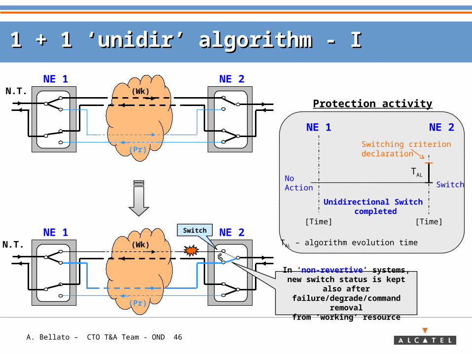
1 + 1 ‘unidir’ algorithm - I1 + 1 ‘unidir’ algorithm - I
N.T. (Wk)
(Pr)
NE 1 NE 2
N.T. (Wk)
(Pr)
NE 1 NE 2
SwitchNo Action
Unidirectional Switch completed
NE 1 NE 2
Switching criterion declaration
[Time][Time]
TAL
TAL – algorithm evolution time
Protection activity
Switch
In ‘non-revertive’ systems, new switch status is kept also after
failure/degrade/command removalfrom ‘working’ resource
A. Bellato – CTO T&A Team - OND 47
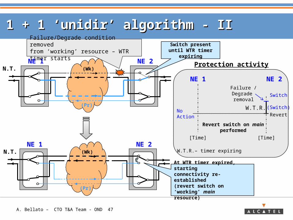
1 + 1 ‘unidir’ algorithm - II1 + 1 ‘unidir’ algorithm - II
N.T. (Wk)
(Pr)
NE 1 NE 2
Switch
No Action
Revert switch on main performed
NE 1 NE 2Failure / Degrade removal
[Time][Time]
W.T.R.
W.T.R.– timer expiring
Protection activityN.T. (Wk)
(Pr)
NE 1 NE 2
Switch present until WTR timer expiring
Failure/Degrade condition removedfrom ‘working’ resource – WTR timer starts
At WTR timer expired, starting connectivity re-established (revert switch on ‘working’ main resource)
(Switch)
Revert
A. Bellato – CTO T&A Team - OND 48
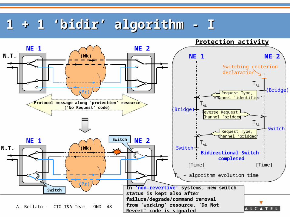
1 + 1 ‘bidir’ algorithm - I1 + 1 ‘bidir’ algorithm - I
N.T. (Wk)
(Pr)
NE 1 NE 2
N.T. (Wk)
(Pr)
NE 1 NE 2
Protocol message along ‘protection’ resource(‘No Request’ code)
Switch
Switch
(Bridge)
(Bridge)
Bidirectional Switch completed
NE 1 NE 2
Switching criterion declaration
Request Type, Channel ‘identifier’
Reverse Request, Channel ‘bridged
Request Type, Channel ‘bridged’
Switch
Switch
[Time][Time]
TAL – algorithm evolution time
TAL
TAL
TAL
TAL
Protection activity
In ‘non-revertive’ systems, new switch status is kept also after failure/degrade/command removalfrom ‘working’ resource, ‘Do Not Revert’ code is signaled
A. Bellato – CTO T&A Team - OND 49
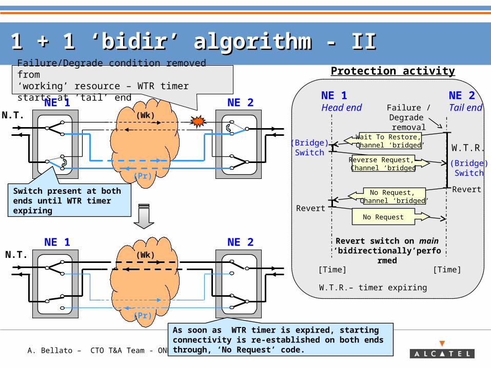
1 + 1 ‘bidir’ algorithm - II1 + 1 ‘bidir’ algorithm - II
N.T. (Wk)
(Pr)
NE 1 NE 2
N.T. (Wk)
(Pr)
NE 1 NE 2
Failure/Degrade condition removed from ‘working’ resource – WTR timer starts at ‘tail’ end
Switch present at both ends until WTR timer expiring
(Bridge)Switch
(Bridge)Switch
NE 1Head end
NE 2Tail end
Wait To Restore, Channel ‘bridged’
No Request, Channel ‘bridged’
[Time][Time]
Protection activity
Failure / Degrade removal
W.T.R.
W.T.R.– timer expiring
Revert switch on main ‘bidirectionally’perfor
med
Revert
Revert
Reverse Request, Channel ‘bridged
No Request
As soon as WTR timer is expired, starting connectivity is re-established on both ends through, ‘No Request’ code.
A. Bellato – CTO T&A Team - OND 50
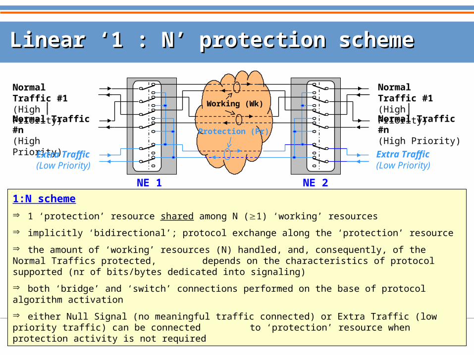
Linear ‘1 : N’ protection schemeLinear ‘1 : N’ protection scheme
NE 1
Normal Traffic #1(High Priority)
Normal Traffic #n(High Priority)
Extra Traffic(Low Priority)
NE 2
1:N scheme
1 ‘protection’ resource shared among N (1) ‘working’ resources
implicitly ‘bidirectional’; protocol exchange along the ‘protection’ resource
the amount of ‘working’ resources (N) handled, and, consequently, of the Normal Traffics protected, depends on the characteristics of protocol supported (nr of bits/bytes dedicated into signaling)
both ‘bridge’ and ‘switch’ connections performed on the base of protocol algorithm activation
either Null Signal (no meaningful traffic connected) or Extra Traffic (low priority traffic) can be connected to ‘protection’ resource when protection activity is not required
Protection (Pr)
Working (Wk)
Normal Traffic #1(High Priority)
Normal Traffic #n(High Priority)
Extra Traffic(Low Priority)
A. Bellato – CTO T&A Team - OND 51
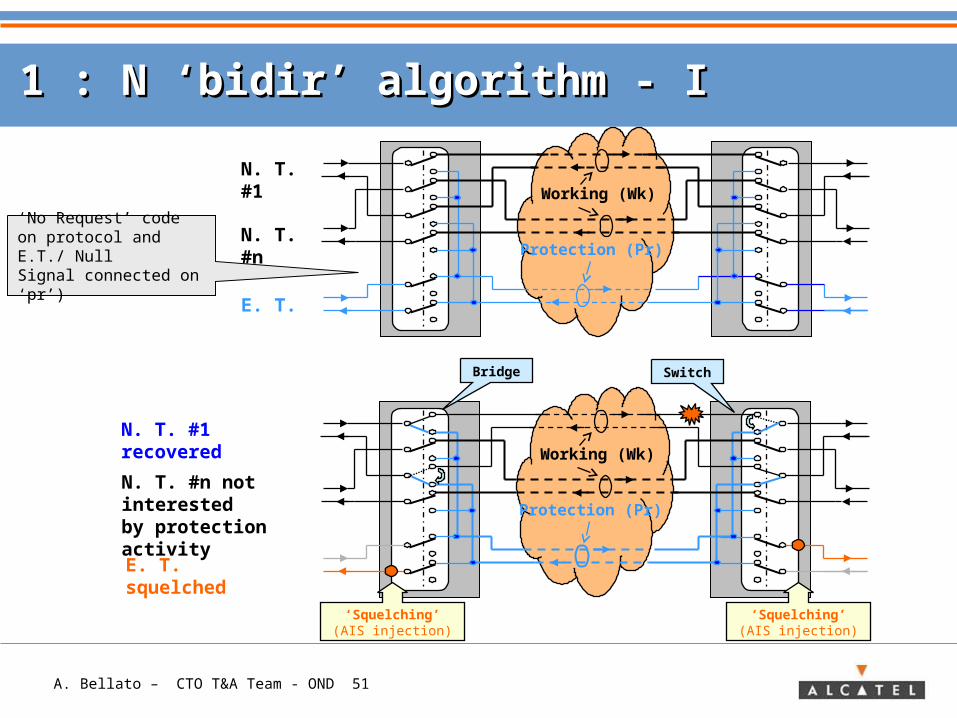
1 : N ‘bidir’ algorithm - I1 : N ‘bidir’ algorithm - I
Protection (Pr)
Working (Wk)
Protection (Pr)
Working (Wk)
Bridge Switch
N. T. #1 recovered
N. T. #n not interested by protection activity
N. T. #1
N. T. #n
E. T.
‘No Request’ code on protocol and E.T./ Null Signal connected on ‘pr’)
E. T. squelched
‘Squelching’(AIS injection)
‘Squelching’(AIS injection)
A. Bellato – CTO T&A Team - OND 52
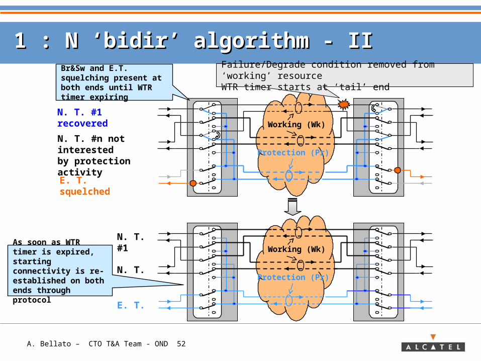
1 : N ‘bidir’ algorithm - II1 : N ‘bidir’ algorithm - II
Protection (Pr)
Working (Wk)
N. T. #1
N. T. #n
E. T.
Protection (Pr)
Working (Wk)
N. T. #1 recovered
N. T. #n not interested by protection activity
E. T. squelched
Br&Sw and E.T. squelching present at both ends until WTR timer expiring
Failure/Degrade condition removed from ‘working’ resourceWTR timer starts at ‘tail’ end
As soon as WTR timer is expired, starting connectivity is re-established on both ends through protocol
A. Bellato – CTO T&A Team - OND 53
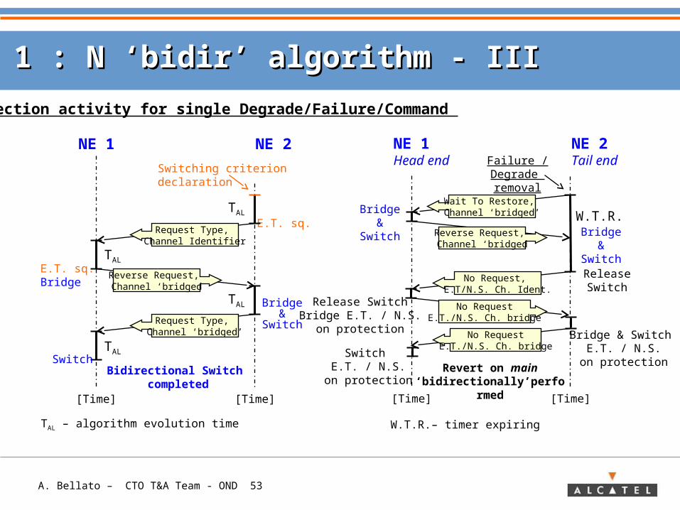
1 : N ‘bidir’ algorithm - III1 : N ‘bidir’ algorithm - III
E.T. sq.
E.T. sq.Bridge
Bidirectional Switch completed
NE 1 NE 2
Switching criterion declaration
Request Type, Channel Identifier
Reverse Request, Channel ‘bridged
Request Type, Channel ‘bridged’
Bridge&
Switch
Switch
[Time][Time]
TAL – algorithm evolution time
TAL
TAL
TAL
TAL
Protection activity for single Degrade/Failure/Command
Bridge&
Switch
Bridge&
Switch
NE 1Head end
NE 2Tail end
Wait To Restore, Channel ‘bridged’
No Request, E.T/N.S. Ch. Ident.
[Time][Time]
Failure / Degrade removal
W.T.R.
W.T.R.– timer expiring
Revert on main ‘bidirectionally’perfor
med
Release Switch
Release SwitchBridge E.T. / N.S.
on protection
Reverse Request, Channel ‘bridged
No RequestE.T./N.S. Ch. bridge
No RequestE.T./N.S. Ch. bridge
Bridge & Switch E.T. / N.S.
on protectionSwitch
E.T. / N.S.on protection
A. Bellato – CTO T&A Team - OND 54
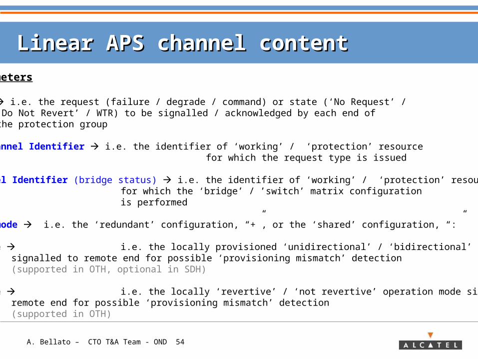
Linear APS channel contentLinear APS channel content
Protocol Parameters
• Request Type i.e. the request (failure / degrade / command) or state (‘No Request’ / ‘Do Not Revert’ / WTR) to be signalled / acknowledged by each end of the protection group
• Requesting Channel Identifier i.e. the identifier of ‘working’ / ‘protection’ resource for which the request type is issued
• Bridged Channel Identifier (bridge status) i.e. the identifier of ‘working’ / ‘protection’ resource for which the ‘bridge’ / ’switch’ matrix configuration is performed
• Architecture mode i.e. the ‘redundant’ configuration, “+”, or the ‘shared’ configuration, “:”
• Switching mode i.e. the locally provisioned ‘unidirectional’ / ‘bidirectional’ switching modesignalled to remote end for possible ‘provisioning mismatch’ detection (supported in OTH, optional in SDH)
• Operation mode i.e. the locally ‘revertive’ / ‘not revertive’ operation mode signalled to remote end for possible ‘provisioning mismatch’ detection (supported in OTH)
A. Bellato – CTO T&A Team - OND 55
Squelching in linear schemesSquelching in linear schemes
Extra Traffic squelchingThis type of squelching is needed in every type of scheme, linear or ring,
supporting traffic configuration on the ‘Low Priority’ channels (Protection channels). This traffic, called ‘extra’ with respect that one configured on ‘High Priority’
channels called ‘normal’, is pre-empted when the ‘Low Priority’ channels are required for
protecting ‘normal’ traffic. The access to the ‘Low Priority’ by Normal Traffic might lead to traffic
misconnected, if no specific mechanism was implemented: Extra Traffic squelching performed before
any matrix re-configuration (Bridge/Switch) avoids this potential problem.
In linear 1:N schemes, Extra Traffic squelching implies that ‘end’ nodes forces a defined alarm signal (AIS) towards the Extra Traffic user.
A. Bellato – CTO T&A Team - OND 56
N.T.NE 2
E.T.
N.T.NE 1
E.T.
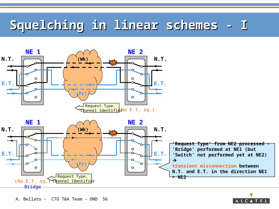
Squelching in linear schemes - ISquelching in linear schemes - I
(Wk)
(Pr)
Request Type, Channel Identifier
N.T.NE 2
E.T.
N.T.NE 1
E.T.
(Wk)
(Pr)
(No E.T. sq.)Bridge
(No E.T. sq.)
Request Type, Channel Identifier
‘Request Type’ from NE2 processed - ‘Bridge’ performed at NE1 (but ‘Switch’ not performed yet at NE2) transient misconnection between N.T. and E.T. in the direction NE1 > NE2
A. Bellato – CTO T&A Team - OND 57
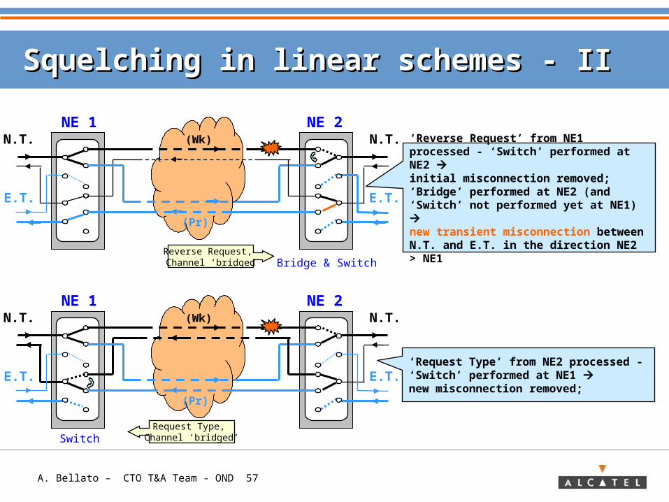
Squelching in linear schemes - IISquelching in linear schemes - II
N.T.NE 2
E.T.
N.T.NE 1
E.T.
(Wk)
(Pr)
Reverse Request, Channel ‘bridged Bridge & Switch
‘Reverse Request’ from NE1 processed - ‘Switch’ performed at NE2 initial misconnection removed;‘Bridge’ performed at NE2 (and ‘Switch’ not performed yet at NE1) new transient misconnection between N.T. and E.T. in the direction NE2 > NE1
N.T.NE 2
E.T.
N.T.NE 1
E.T.
(Wk)
(Pr)
SwitchRequest Type,
Channel ‘bridged’
‘Request Type’ from NE2 processed - ‘Switch’ performed at NE1 new misconnection removed;
A. Bellato – CTO T&A Team - OND 58
ContentContent
> Transport Network Concept
> Need for traffic protection
> Methods for traffic protection: Protection & Restoration
> Basics for traffic protection
> Protection Schemes in Transport Networks• Linear• Ring
> APPENDIX: Protection schemes in SDH/ Sonet/ OTN
A. Bellato – CTO T&A Team - OND 59
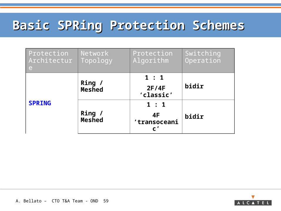
Basic SPRing Protection SchemesBasic SPRing Protection Schemes
Protection Architecture
Network Topology
Protection Algorithm
Switching Operation
SPRING
Ring / Meshed1 : 1
2F/4F ‘classic’bidir
Ring / Meshed1 : 1
4F ‘transoceanic’
bidir
A. Bellato – CTO T&A Team - OND 60
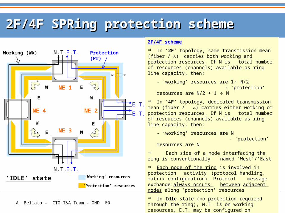
2F/4F SPRing protection scheme2F/4F SPRing protection scheme
NE 1
NE 2
NE 3
NE 4
Working (Wk) Protection (Pr)
N.T. E.T.
N.T. E.T.
E.T.
E.T.
2F/4F scheme
In ‘2F’ topology, same transmission mean (fiber / ) carries both working and protection resources. If N is total number of resources (channels) available as ring line capacity, then:
- ‘working’ resources are 1 N/2 - ‘protection’ resources are N/2 + 1 N
In ‘4F’ topology, dedicated transmission mean (fiber / ) carries either working or protection resources. If N is total number of resources (channels) available as ring line capacity, then:
- ‘working’ resources are N - ‘protection’ resources are N
Each side of a node interfacing the ring is conventionally named ‘West’/’East
Each node of the ring is involved in protection activity (protocol handling, matrix configuration). Protocol message exchange always occurs between adjacent nodes along ‘protection’ resources
In Idle state (no protection required through the ring), N.T. is on working resources, E.T. may be configured on protection resources. Protocol signaling carries ‘No request’ code from each node to the adjacent one
‘IDLE’ state
W E
E
W
WE
W
E
‘Protection’ resources
‘Working’ resources
A. Bellato – CTO T&A Team - OND 61
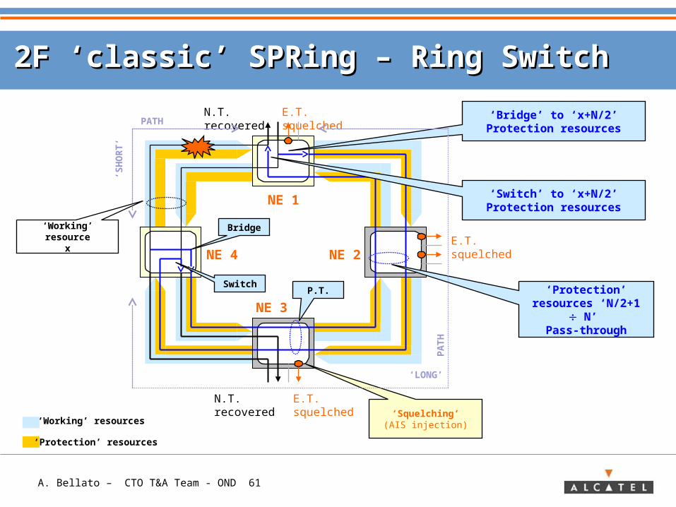
2F ‘classic’ SPRing – Ring Switch2F ‘classic’ SPRing – Ring Switch
NE 1
NE 2
NE 3
NE 4
E.T. squelched
E.T. squelched
N.T. recovered
E.T. squelchedN.T. recovered ‘Bridge’ to ‘x+N/2’ Protection resources
Bridge
Switch
‘Squelching’(AIS injection)
‘Protection’ resources ‘N/2+1 N’
Pass-through
PATH‘S
HO
RT
’
‘LONG’
PA
TH
‘Switch’ to ‘x+N/2’ Protection resources
P.T.
‘Working’ resourcex
‘Protection’ resources
‘Working’ resources
A. Bellato – CTO T&A Team - OND 62
2F ‘classic’ SPRing – Ring Switch2F ‘classic’ SPRing – Ring Switch
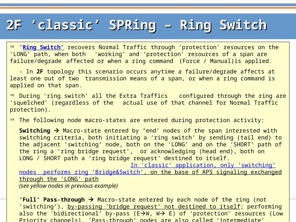
‘Ring Switch’ recovers Normal Traffic through ‘protection’ resources on the ‘LONG’ path, when both ‘working’ and ‘protection’ resources of a span are failure/degrade affected or when a ring command (Force / Manual)is applied.
- In 2F topology this scenario occurs anytime a failure/degrade affects at least one out of two transmission means of a span, or when a ring command is applied on that span.
During ‘ring switch’ all the Extra Traffics configured through the ring are ‘squelched’ (regardless of the actual use of that channel for Normal Traffic protection).
The following node macro-states are entered during protection activity:
Switching Macro-state entered by ‘end’ nodes of the span interested with switching criteria, both initiating a ‘ring switch’ by sending (tail end) to the adjacent ‘switching’ node, both on the ‘LONG’ and on the ‘SHORT’ path of the ring a ‘ring bridge request’, or acknowledging (head end), both on LONG / SHORT path a ‘ring bridge request’ destined to itself. In ‘classic’ application, only ‘switching’ nodes performs ring ‘Bridge&Switch’, on the base of APS signaling exchanged through the ‘LONG’ path(see yellow nodes in previous example)
‘Full’ Pass-through Macro-state entered by each node of the ring (not ‘switching’), by-passing ‘bridge request’ not destined to itself; performing also the ‘bidirectional’ by-pass (EW, W E) of ‘protection’ resources (Low Priority channels). ‘Pass-through’ nodes are also called ‘intermediate’ nodes.(see grey nodes in previous example)
A. Bellato – CTO T&A Team - OND 63
4F ‘classic’ SPRing – Ring Switch4F ‘classic’ SPRing – Ring Switch
‘Squelching’(AIS injection)
NE 1
NE 2
NE 3
NE 4
E.T. squelched
E.T. squelched
N.T. recovered
E.T. squelchedN.T. recovered
Bridge
Bridge
Switch
Switch
P.T.
PATH
‘SH
OR
T’
‘LONG’
PA
TH
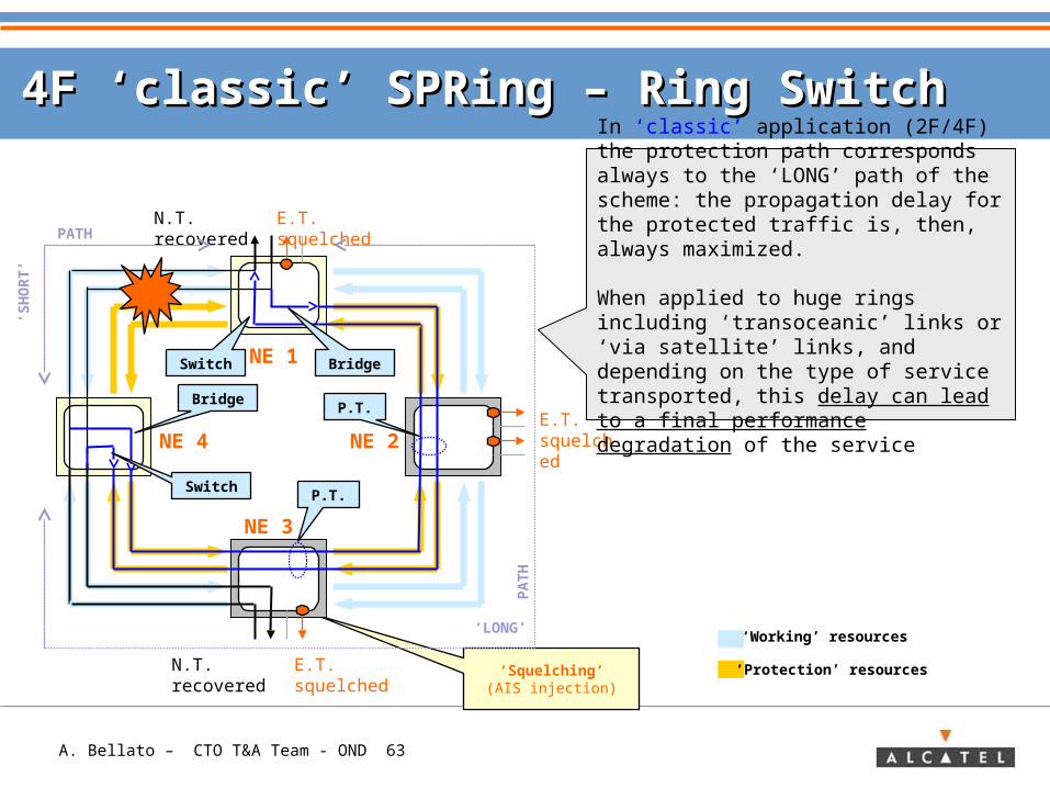
In ‘classic’ application (2F/4F) the protection path corresponds always to the ‘LONG’ path of the scheme: the propagation delay for the protected traffic is, then, always maximized. When applied to huge rings including ‘transoceanic’ links or ‘via satellite’ links, and depending on the type of service transported, this delay can lead to a final performance degradation of the service
‘Protection’ resources
‘Working’ resources
P.T.
A. Bellato – CTO T&A Team - OND 64
4F ‘transoceanic’ SPRing – Ring Switch4F ‘transoceanic’ SPRing – Ring Switch
NE 1
NE 2
NE 3
NE 4
E.T. squelched
E.T. squelched
N.T. recovered
E.T. squelchedN.T. recovered
Bridge
BridgeSwitch
Switch
Pass-through
PATH
‘SH
OR
T’
‘LONG’
PA
TH
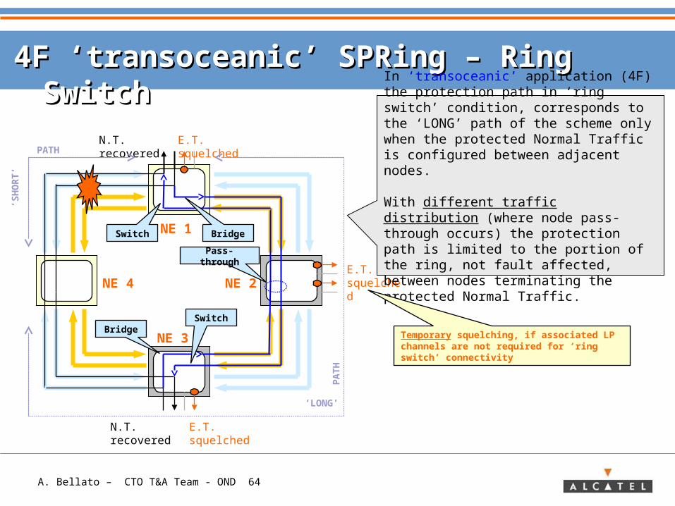
In ‘transoceanic’ application (4F) the protection path in ‘ring switch’ condition, corresponds to the ‘LONG’ path of the scheme only when the protected Normal Traffic is configured between adjacent nodes.
With different traffic distribution (where node pass-through occurs) the protection path is limited to the portion of the ring, not fault affected, between nodes terminating the protected Normal Traffic.
Temporary squelching, if associated LP channels are not required for ‘ring switch’ connectivity
A. Bellato – CTO T&A Team - OND 65
4F SPRing – Ring Switch - I4F SPRing – Ring Switch - I
‘Ring Switch’, in 4F topology occurs anytime a failure/degrade affects at least two out of four transmission means of a span, in such a way that both one ‘working’ and one
‘protection’ resources results fault affected or when a ring command is applied on that span. As for ‘2F ring’, Normal Traffic is recovered through ‘protection’ resources on the ‘LONG’ path.
In ‘classic’ (also called ‘terrestrial’) application, same behaviour already described about ‘2F’ ring’, same E.T. squelching policy and same node macro-states apply.
In ‘transoceanic’ application, current standard reference (SDH) states that during ‘ring switch’ all the Extra Traffics configured through the ring are ‘squelched’; after the ‘ring switch’ is performed, those Low Priority channels not used for Normal Traffic protection are re-connected to Extra Traffic.
This is a slow process possibly using ‘communication channels’ between the nodes of the ring, i.e. control plane, for E.T. re-configuration (protection protocol independent).
Both ‘distributed’ ring switch and Extra Traffic recovery is applicable, due to the knowledge of the whole ring connectivity at each node of the ring (see ‘Traffic Map’).
The following node macro-states are entered during protection activity:
A. Bellato – CTO T&A Team - OND 66
4F SPRing – Ring Switch - II4F SPRing – Ring Switch - II
Switching Macro-state entered by ’end’ node of the span interested with switching criteria, initiating a ‘ring switch’ by sending (tail end) to the adjacent ‘switching’ node, both on the ‘LONG’ and on the ‘SHORT’ path of the ring a ‘ring bridge request’, or acknowledging (head end), both on LONG/SHORT path a ‘ring bridge request’ destined to itself. Switching nodes performs ring ‘Bridge&Switch’ only when adding/dropping (terminating) Normal Traffic to be protected on the base of APS signaling exchanged through the ‘LONG’ path (see yellow nodes in previous example).
‘Full’ Pass-through Macro-state entered by each node of the ring (not ‘switching’), by-passing ‘bridge request’ not destined to itself. The same protocol specified in ‘classic’ application is used. ‘Pass-through’ nodes performs ring ‘Bridge&Switch’ only when adding/dropping (terminating) Normal Traffic to be protected on the base of APS signaling received by both switching nodes; otherwise, they realize the ‘bidirectional by-pass (EW, W E) of ‘protection’ resources (Low Priority channels). ‘Pass-through’ nodes are also called ‘intermediate’ nodes (see grey nodes in previous example).
A. Bellato – CTO T&A Team - OND 67
SPRing APS channel contentSPRing APS channel content
Protocol parameters
• Request Type i.e. the request (failure / degrade / command) or state (‘No Request’ / WTR) to be signalled / acknowledged by opposite end of the span interested
• Destination Node i.e. the adjacent node addressed by APS signalling
• Source Node i.e. the node sourcing the APS signaling
• Path i.e. the portion of the ring interested by APS signaling, ‘short’ ,(span fault affected), or ‘long’, (the remaining spans of the ring)
• Bridge status i.e. ‘idle’, ‘bridge’ , ’bridge & switch’ matrix configuration
A. Bellato – CTO T&A Team - OND 68
4F SPRing – Span switch4F SPRing – Span switch
NE 1
NE 2
NE 3
NE 4
E.T. kept
E.T. kept
N.T. recovered
E.T. squelchedN.T. recovered
Bridge
Switch
K - pass-through
PATH
‘SH
OR
T’
‘LONG’
PA
TH
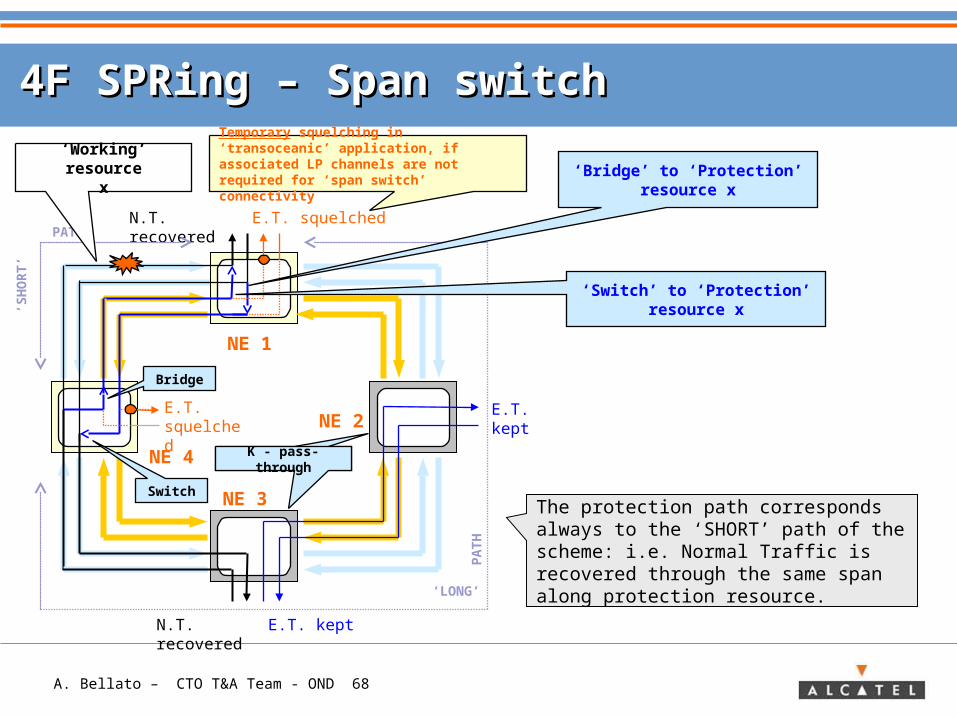
The protection path corresponds always to the ‘SHORT’ path of the scheme: i.e. Normal Traffic is recovered through the same span along protection resource.
E.T. squelched
Temporary squelching in ‘transoceanic’ application, if associated LP channels are not required for ‘span switch’ connectivity
K - pass-through
‘Working’ resourcex ‘Bridge’ to ‘Protection’
resource x
‘Switch’ to ‘Protection’ resource x
A. Bellato – CTO T&A Team - OND 69
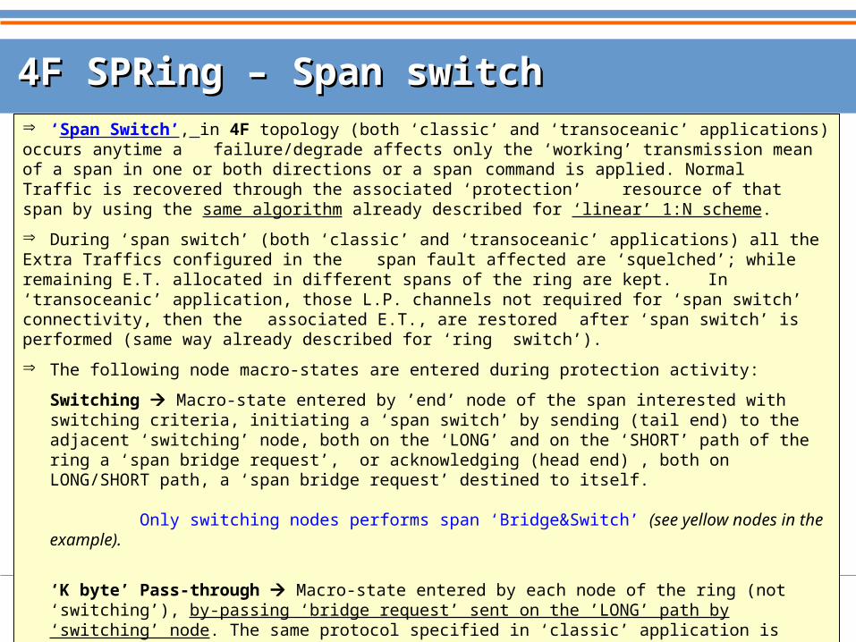
4F SPRing – Span switch4F SPRing – Span switch ‘Span Switch’, in 4F topology (both ‘classic’ and ‘transoceanic’ applications) occurs anytime a failure/degrade affects only the ‘working’ transmission mean of a span in one or both directions or a span command is applied. Normal Traffic is recovered through the associated ‘protection’ resource of that span by using the same algorithm already described for ‘linear’ 1:N scheme.
During ‘span switch’ (both ‘classic’ and ‘transoceanic’ applications) all the Extra Traffics configured in the span fault affected are ‘squelched’; while remaining E.T. allocated in different spans of the ring are kept. In ‘transoceanic’ application, those L.P. channels not required for ‘span switch’ connectivity, then the associated E.T., are restored after ‘span switch’ is performed (same way already described for ‘ring switch’).
The following node macro-states are entered during protection activity:
Switching Macro-state entered by ’end’ node of the span interested with switching criteria, initiating a ‘span switch’ by sending (tail end) to the adjacent ‘switching’ node, both on the ‘LONG’ and on the ‘SHORT’ path of the ring a ‘span bridge request’, or acknowledging (head end) , both on LONG/SHORT path, a ‘span bridge request’ destined to itself. Only switching nodes performs span ‘Bridge&Switch’ (see yellow nodes in the example).
‘K byte’ Pass-through Macro-state entered by each node of the ring (not ‘switching’), by-passing ‘bridge request’ sent on the ’LONG’ path by ‘switching’ node. The same protocol specified in ‘classic’ application is used.
‘K byte’ Pass-through nodes do not perform any reconfiguration of local connectivity. ‘K-byte Pass-through nodes are also called ‘intermediate’ nodes. (see grey nodes in the example)
A. Bellato – CTO T&A Team - OND 70
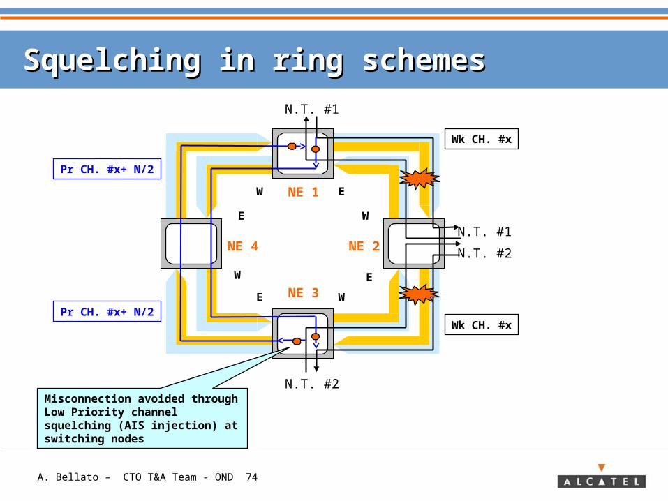
Squelching in ring schemesSquelching in ring schemes
Extra Traffic squelchingThe same considerations already reported for linear schemes apply: the access to the ‘Low Priority’ by Normal Traffic might lead to traffic misconnected, if no specific mechanism was implemented: Extra Traffic squelching performed before any matrix re-configuration (Bridge/Switch/Pass-Through) avoids this potential problem.
In ring schemes, Extra Traffic squelching implies that nodes ‘dropping’ Extra Traffic forces a defined alarm signal (AIS) towards the Extra Traffic user, both in case they enter the ‘switching’ (due to a ring/span switch) or the ‘pass-through’ state.
Besides, nodes performing ‘span switch’ have also to insert the alarm signal (AIS) towards the ring, on ‘Low Priority’ channels carrying possible E.T. passing from the ‘protected’ span through the node.
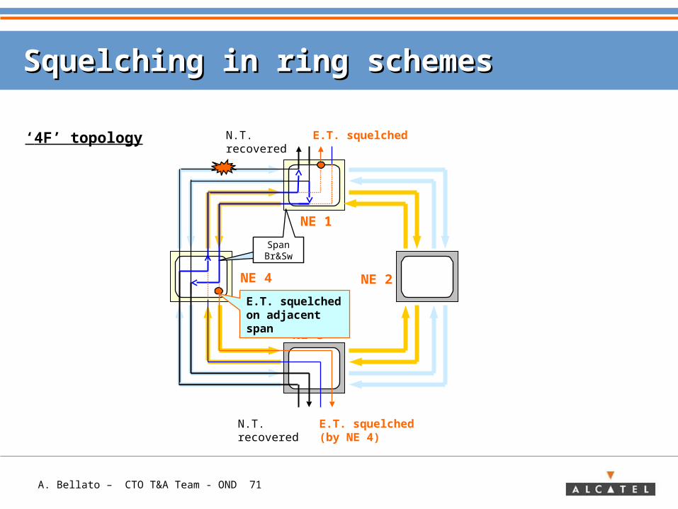
A. Bellato – CTO T&A Team - OND 71
Squelching in ring schemesSquelching in ring schemes
NE 1
NE 2
NE 3
NE 4
N.T. recovered
E.T. squelchedN.T. recovered
Span Br&Sw
E.T. squelched on adjacent span
Span Br&Sw
E.T. squelched (by NE 4)
‘4F’ topology
A. Bellato – CTO T&A Team - OND 72
Squelching in ring schemesSquelching in ring schemes
Ring squelchingThis type of squelching is needed in 2F/4F ‘classical’ SPRing, when a node of the ring becomes ‘isolated’ either for node failure or for multiple failures requiring ‘ring switch’ at both sides.In this case, due to the ring switch action performed by nodes adjacent the isolated one (i.e. ‘switching’ nodes), possible traffics terminated into isolated node and allocated on same ‘High Priority’ channels for both sides (West/East), would be misconnected by accessing the same ‘Low Priority’ channels.
This condition is avoided by inserting at the ‘switching’ nodes AIS signal on ‘protection channels’, making them unavailable through the ring (the AIS insertion is performed bi- directionally).
A. Bellato – CTO T&A Team - OND 73
Squelching in ring schemesSquelching in ring schemes
NE 1
NE 2
NE 3
NE 4
N.T. #1
N.T. #2
N.T. #1
N.T. #2
W E
E
W
WE
W
E
Wk Ch. #x
Wk Ch. #x
Pr Ch. #x+ N/2
Pr Ch. #x+ N/2
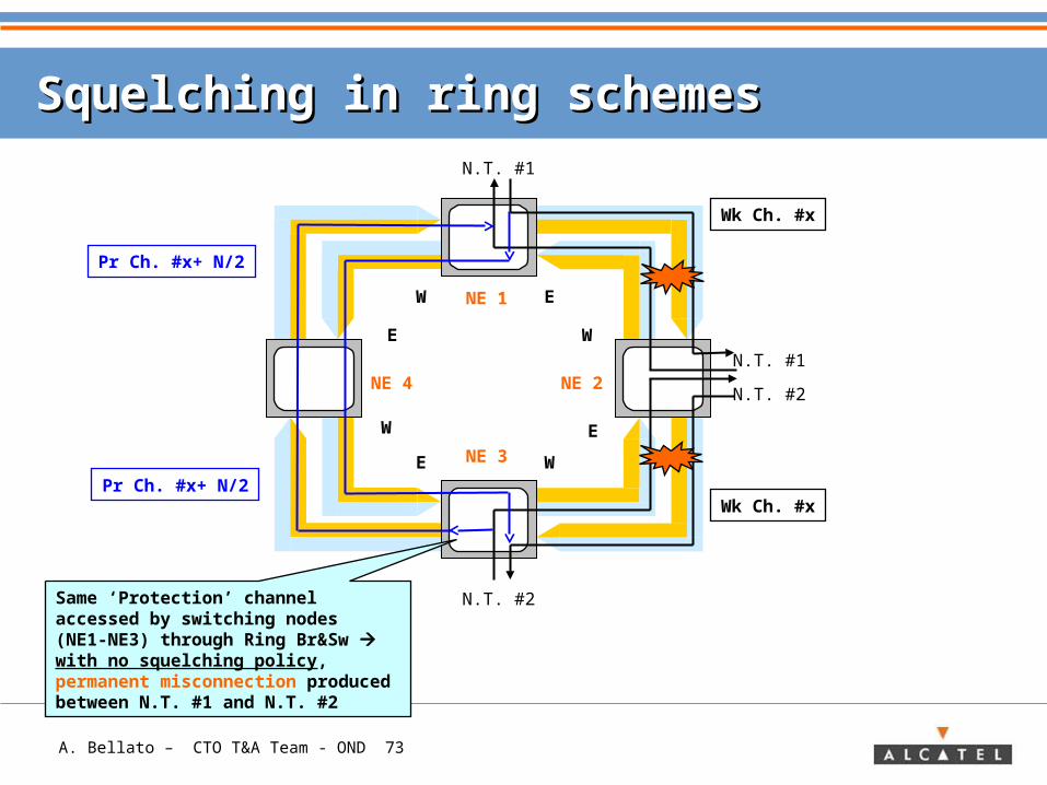
Same ‘Protection’ channel accessed by switching nodes (NE1-NE3) through Ring Br&Sw with no squelching policy, permanent misconnection produced between N.T. #1 and N.T. #2
A. Bellato – CTO T&A Team - OND 74
Squelching in ring schemesSquelching in ring schemes
NE 1
NE 2
NE 3
NE 4
N.T. #1
N.T. #2
N.T. #1
N.T. #2
W E
E
W
WE
W
E
Wk CH. #x
Wk CH. #x
Pr CH. #x+ N/2
Pr CH. #x+ N/2
Misconnection avoided through Low Priority channel squelching (AIS injection) at switching nodes
A. Bellato – CTO T&A Team - OND 75
Total N paths
N/2 ‘wk‘ resources
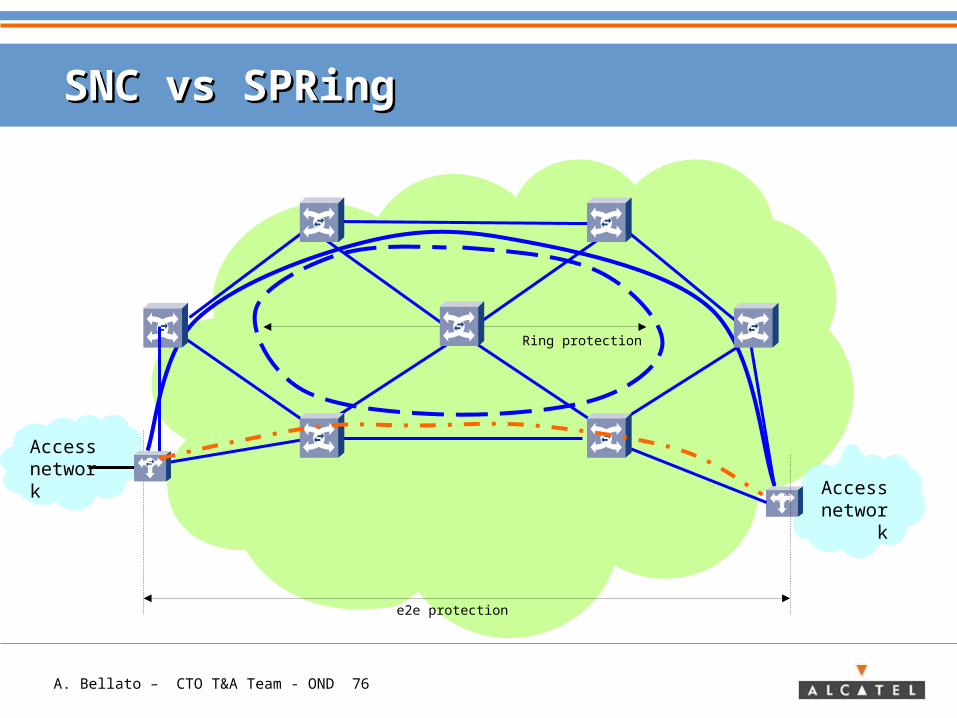
SNC vs SPRingSNC vs SPRing
N/2 ‘wk‘ resources
N/2
‘w
k‘ r
eso
urc
es
N/2
‘wk‘ re
sou
rces
N ‘wk‘ resourcesUp to 2xN paths Up to N paths
WITH ‘ADJACENT’ TRAFFIC ALLOCATIONTHE PROTECTION SCHEME WITH MOST PROFITABLE BANDWIDTH
OCCUPATIONIS…
WITH ‘ADJACENT’ TRAFFIC ALLOCATIONTHE PROTECTION SCHEME WITH MOST PROFITABLE BANDWIDTH
OCCUPATIONIS…
SPRING
WITH ‘HUBBED’ TRAFFIC ALLOCATIONTHE PROTECTION SCHEME WITH MOST PROFITABLE BANDWIDTH
OCCUPATIONIS…
WITH ‘HUBBED’ TRAFFIC ALLOCATIONTHE PROTECTION SCHEME WITH MOST PROFITABLE BANDWIDTH
OCCUPATIONIS…
SNC
A. Bellato – CTO T&A Team - OND 76
SNC vs SPRingSNC vs SPRing
Access networ
k
Accessnetwork
e2e protection
Ring protection
A. Bellato – CTO T&A Team - OND 77
ContentContent
> Transport Network Concept
> Need for traffic protection
> Methods for traffic protection: Protection & Restoration
> Basics for traffic protection
> Protection Schemes in Transport Networks• Restoration
> APPENDIX: Protection schemes in SDH/ Sonet/ OTN
A. Bellato – CTO T&A Team - OND 78
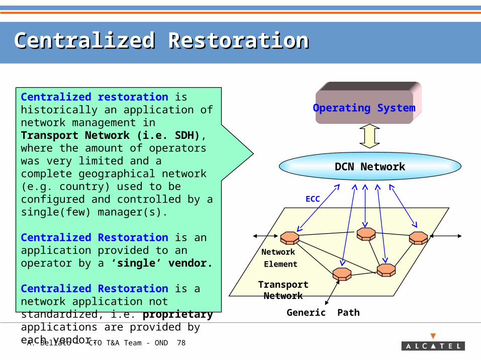
Centralized RestorationCentralized Restoration
Operating System
Transport Network
Centralized restoration is historically an application of network management in Transport Network (i.e. SDH), where the amount of operators was very limited and a complete geographical network (e.g. country) used to be configured and controlled by a single(few) manager(s).
Centralized Restoration is an application provided to an operator by a ‘single’ vendor.
Centralized Restoration is a network application not standardized, i.e. proprietary applications are provided by each vendor.
Network
Element
ECC
Generic Path
DCN Network
A. Bellato – CTO T&A Team - OND 79
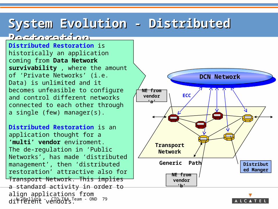
System Evolution - Distributed RestorationSystem Evolution - Distributed Restoration
Distributed Restoration is historically an application coming from Data Network survivability , where the amount of ‘Private Networks’ (i.e. Data) is unlimited and it becomes unfeasible to configure and control different networks connected to each other through a single (few) manager(s).
Distributed Restoration is an application thought for a ‘multi’ vendor enviroment.The de-regulation in ‘Public Networks’, has made ‘distributed management’, then ‘distributed restoration’ attractive also for Transport Network. This implies a standard activity in order to align applications from different vendors.
Transport Network
ECC
Generic Path
DCN NetworkDCN Network
Distributed Manger
NE from vendor ‘a’
NE from vendor ‘b’
A. Bellato – CTO T&A Team - OND 80
ContentContent
> Transport Network Concept
> Need for traffic protection
> Methods for traffic protection: Protection & Restoration
> Basics for traffic protection
> Protection Schemes in Transport Networks
> APPENDIX: Protection schemes in SDH/ Sonet/ OTN• Layering• Network• Frame Structure• Schemes• Network Applications• Reference Standards
A. Bellato – CTO T&A Team - OND 81
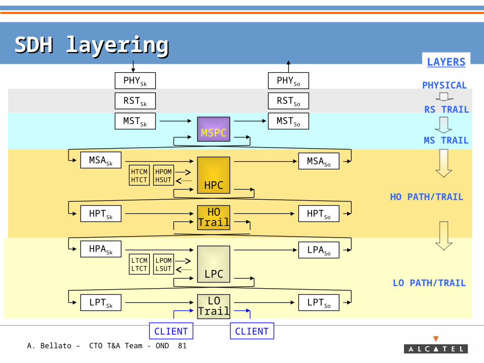
SDH layeringSDH layering
MSTSk
MSASk
HPOMHSUT
HTCMHTCT
MSPC
HPC
LO PATH/TRAIL
HO PATH/TRAIL
MS TRAIL
LAYERS
RSTSk
PHYSk
MSASo
MSTSo
RSTSo
PHYSo
RS TRAIL
PHYSICAL
HPTSoHPTSk
CLIENT CLIENT
HOTrail
HPASk
LPOMLSUT
LTCMLTCT
LPC
LPASo
LPTSoLPTSkLO
Trail
A. Bellato – CTO T&A Team - OND 82
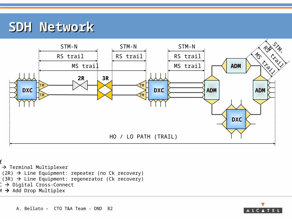
SDH NetworkSDH Network
2R 3R
ADM
ADM ADM
STM-N
MS trail
RS trail RS trail
STM-N STM-N
RS trail
MS trail
HO / LO PATH (TRAIL)
KEYTM Terminal MultiplexerLE (2R) Line Equipment: repeater (no Ck recovery)LE (3R) Line Equipment: regenerator (Ck recovery)DXC Digital Cross-ConnectADM Add Drop Multiplex
DXC
DXCTM
TM
STM-
NRS trail
MS trail
DXCTM
TM
A. Bellato – CTO T&A Team - OND 83
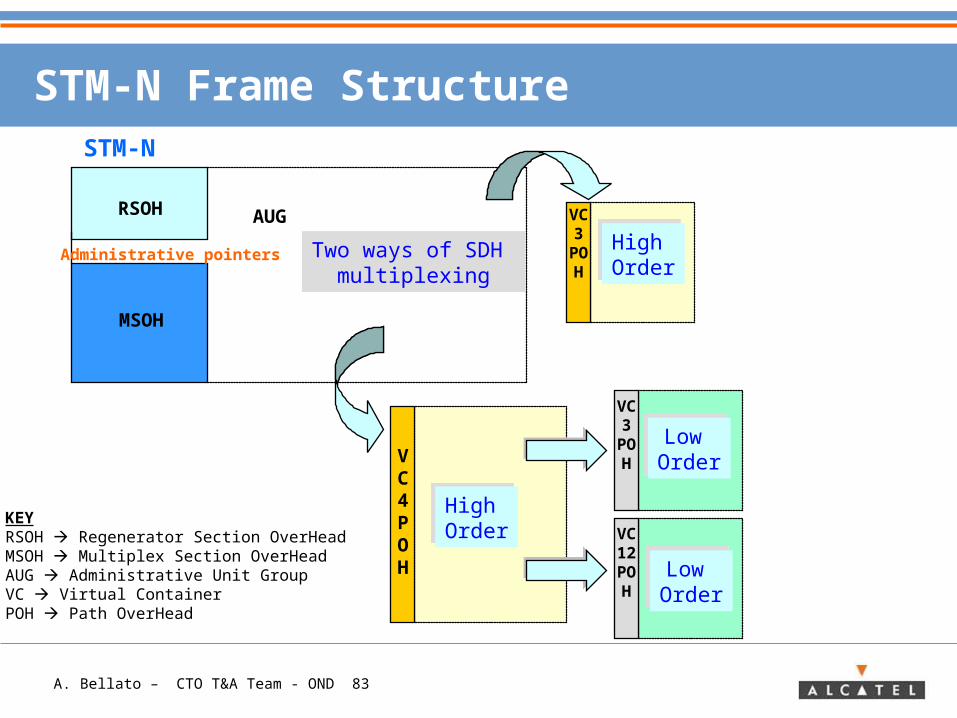
STM-N Frame Structure
RSOH AUG
MSOH
VC4POH
VC3POH
VC12POH
VC3POH
Administrative pointers Two ways of SDH multiplexing
High OrderHigh Order
Low OrderLow Order
Low OrderLow Order
High OrderHigh Order
STM-N
KEYRSOH Regenerator Section OverHeadMSOH Multiplex Section OverHead AUG Administrative Unit GroupVC Virtual ContainerPOH Path OverHead
A. Bellato – CTO T&A Team - OND 84
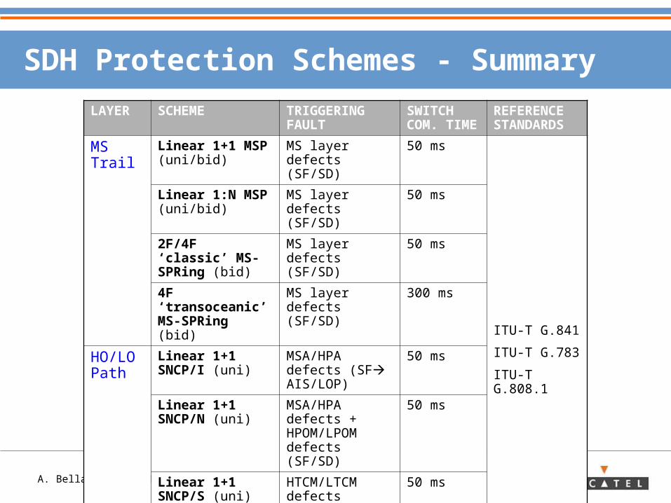
SDH Protection Schemes - Summary
LAYER SCHEME TRIGGERING FAULT
SWITCH COM. TIME
REFERENCE STANDARDS
MS Trail
Linear 1+1 MSP (uni/bid)
MS layer defects (SF/SD)
50 ms
ITU-T G.841
ITU-T G.783
ITU-T G.808.1
Linear 1:N MSP (uni/bid)
MS layer defects (SF/SD)
50 ms
2F/4F ‘classic’ MS-SPRing (bid)
MS layer defects (SF/SD)
50 ms
4F ‘transoceanic’ MS-SPRing (bid)
MS layer defects (SF/SD)
300 ms
HO/LO Path
Linear 1+1 SNCP/I (uni)
MSA/HPA defects (SF AIS/LOP)
50 ms
Linear 1+1 SNCP/N (uni)
MSA/HPA defects + HPOM/LPOM defects (SF/SD)
50 ms
Linear 1+1 SNCP/S (uni)
HTCM/LTCM defects (N1/N2 byte SF/SD)
50 ms
HO/LO Trail
Linear 1+1 VC Trail (uni/bid)
SNCP/N defects (SF/SD)
50 ms
A. Bellato – CTO T&A Team - OND 85
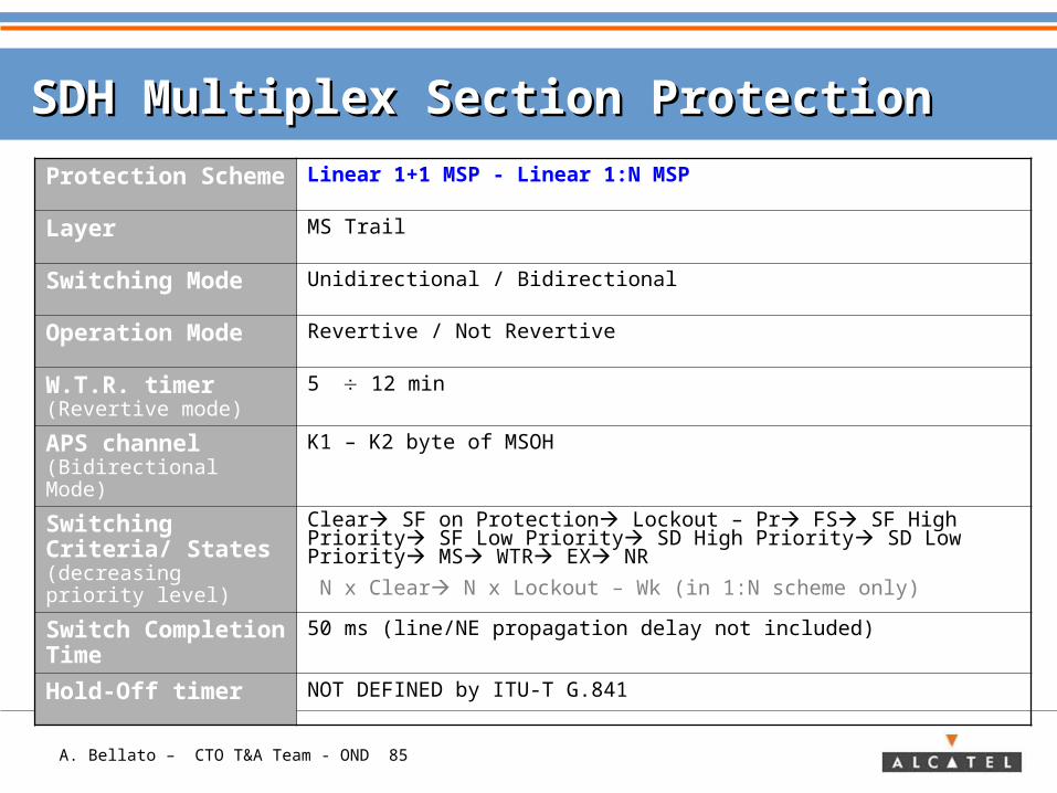
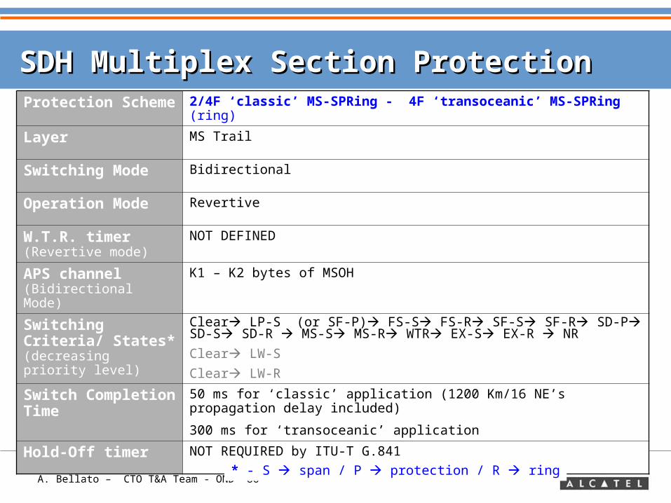
SDH Multiplex Section Protection SDH Multiplex Section Protection
Protection Scheme
Linear 1+1 MSP - Linear 1:N MSP
Layer MS Trail
Switching Mode Unidirectional / Bidirectional
Operation Mode Revertive / Not Revertive
W.T.R. timer (Revertive mode)
5 12 min
APS channel (Bidirectional Mode)
K1 – K2 byte of MSOH
Switching Criteria/ States (decreasing priority level)
Clear SF on Protection Lockout – Pr FS SF High Priority SF Low Priority SD High Priority SD Low Priority MS WTR EX NR
N x Clear N x Lockout – Wk (in 1:N scheme only)
Switch Completion Time
50 ms (line/NE propagation delay not included)
Hold-Off timer NOT DEFINED by ITU-T G.841
A. Bellato – CTO T&A Team - OND 86
SDH Multiplex Section Protection SDH Multiplex Section Protection Protection Scheme
2/4F ‘classic’ MS-SPRing - 4F ‘transoceanic’ MS-SPRing (ring)
Layer MS Trail
Switching Mode Bidirectional
Operation Mode Revertive
W.T.R. timer (Revertive mode)
NOT DEFINED
APS channel (Bidirectional Mode)
K1 – K2 bytes of MSOH
Switching Criteria/ States* (decreasing priority level)
Clear LP-S (or SF-P) FS-S FS-R SF-S SF-R SD-P SD-S SD-R MS-S MS-R WTR EX-S EX-R NR
Clear LW-S
Clear LW-R
Switch Completion Time
50 ms for ‘classic’ application (1200 Km/16 NE’s propagation delay included)
300 ms for ‘transoceanic’ application
Hold-Off timer NOT REQUIRED by ITU-T G.841
* - S span / P protection / R ring
A. Bellato – CTO T&A Team - OND 87
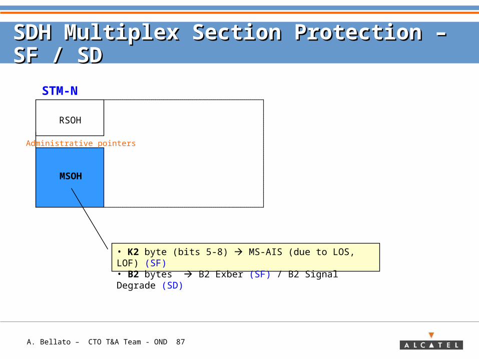
SDH Multiplex Section Protection – SDH Multiplex Section Protection – SF / SD SF / SD
RSOH
MSOH
Administrative pointers
STM-N
• K2 byte (bits 5-8) MS-AIS (due to LOS, LOF) (SF)• B2 bytes B2 Exber (SF) / B2 Signal Degrade (SD)
A. Bellato – CTO T&A Team - OND 88
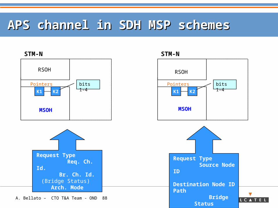
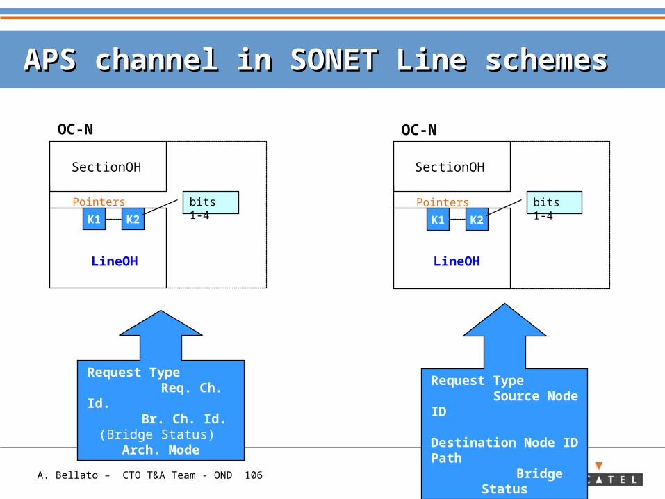
APS channel in SDH MSP schemesAPS channel in SDH MSP schemes
RSOH
Pointers
STM-N
K1 K2
MSOH
bits 1-4
Request Type Req. Ch. Id. Br. Ch. Id. (Bridge Status)
Arch. Mode
RSOH
Pointers
STM-N
K1 K2
MSOH
bits 1-4
Request Type Source Node ID
Destination Node ID Path
Bridge Status
A. Bellato – CTO T&A Team - OND 89
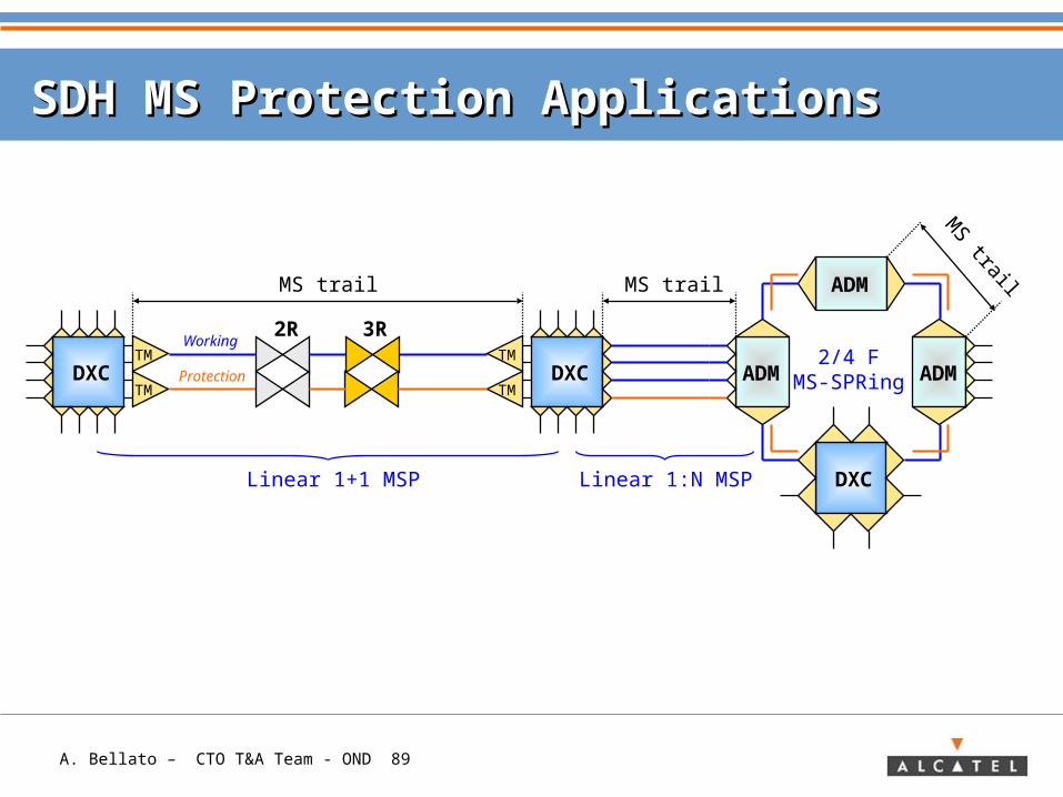
SDH MS Protection ApplicationsSDH MS Protection Applications
2R 3R
ADM
ADM ADM
MS trail MS trail
DXC
DXCTM
TMDXC
TM
TM
MS trail
Linear 1+1 MSP Linear 1:N MSP
2/4 FMS-SPRing
Working
Protection
A. Bellato – CTO T&A Team - OND 90
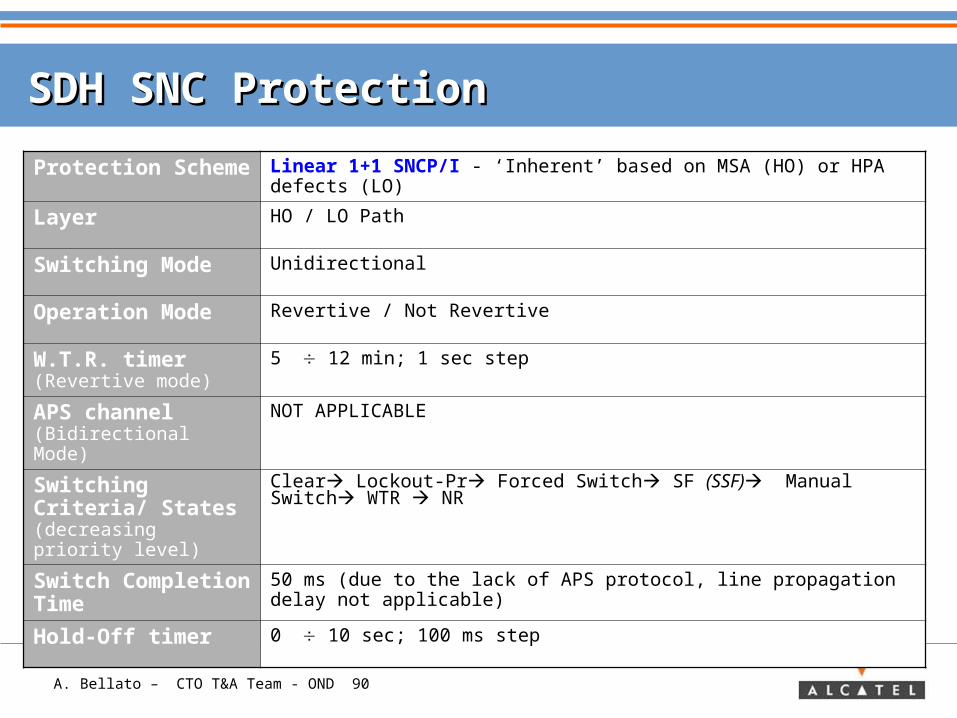
SDH SNC ProtectionSDH SNC Protection
Protection Scheme
Linear 1+1 SNCP/I - ‘Inherent’ based on MSA (HO) or HPA defects (LO)
Layer HO / LO Path
Switching Mode Unidirectional
Operation Mode Revertive / Not Revertive
W.T.R. timer (Revertive mode)
5 12 min; 1 sec step
APS channel (Bidirectional Mode)
NOT APPLICABLE
Switching Criteria/ States (decreasing priority level)
Clear Lockout-Pr Forced Switch SF (SSF) Manual Switch WTR NR
Switch Completion Time
50 ms (due to the lack of APS protocol, line propagation delay not applicable)
Hold-Off timer 0 10 sec; 100 ms step
A. Bellato – CTO T&A Team - OND 91
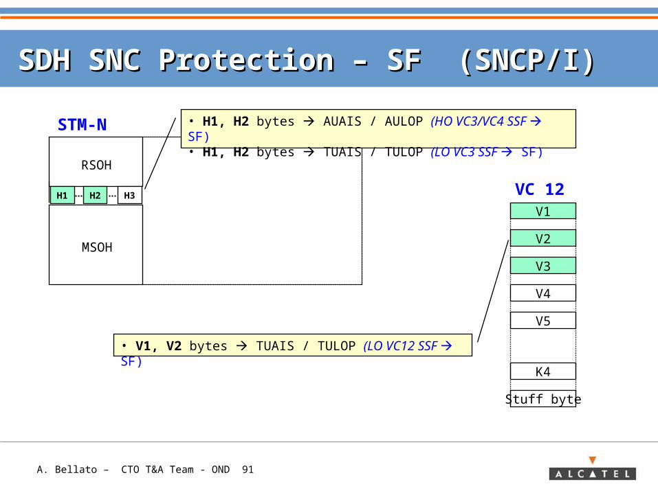
SDH SNC Protection – SDH SNC Protection – SF (SNCP/I)SF (SNCP/I)
RSOH
MSOH
STM-N • H1, H2 bytes AUAIS / AULOP (HO VC3/VC4 SSF SF)• H1, H2 bytes TUAIS / TULOP (LO VC3 SSF SF)
H1 H2 H3
V5
K4
Stuff byte
V1
V2
V3
V4
• V1, V2 bytes TUAIS / TULOP (LO VC12 SSF SF)
VC 12
A. Bellato – CTO T&A Team - OND 92
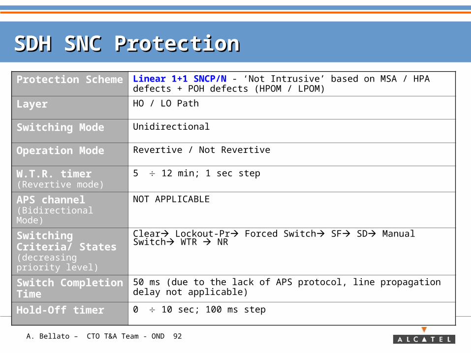
SDH SNC ProtectionSDH SNC Protection
Protection Scheme
Linear 1+1 SNCP/N - ‘Not Intrusive’ based on MSA / HPA defects + POH defects (HPOM / LPOM)
Layer HO / LO Path
Switching Mode Unidirectional
Operation Mode Revertive / Not Revertive
W.T.R. timer (Revertive mode)
5 12 min; 1 sec step
APS channel (Bidirectional Mode)
NOT APPLICABLE
Switching Criteria/ States (decreasing priority level)
Clear Lockout-Pr Forced Switch SF SD Manual Switch WTR NR
Switch Completion Time
50 ms (due to the lack of APS protocol, line propagation delay not applicable)
Hold-Off timer 0 10 sec; 100 ms step
A. Bellato – CTO T&A Team - OND 93
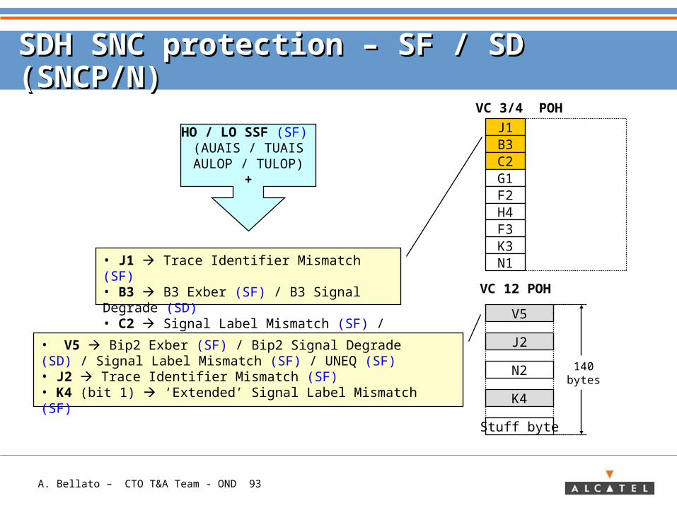
SDH SNC protection – SF / SD (SNCP/N)SDH SNC protection – SF / SD (SNCP/N)
V5
J2
N2
K4
Stuff byte
VC 12 POH
• J1 Trace Identifier Mismatch (SF)• B3 B3 Exber (SF) / B3 Signal Degrade (SD)• C2 Signal Label Mismatch (SF) / UNEQ (SF)
• V5 Bip2 Exber (SF) / Bip2 Signal Degrade (SD) / Signal Label Mismatch (SF) / UNEQ (SF)• J2 Trace Identifier Mismatch (SF)• K4 (bit 1) ‘Extended’ Signal Label Mismatch (SF)
140bytes
VC 3/4 POH
J1B3C2G1F2
K3N1
H4F3
HO / LO SSF (SF) (AUAIS / TUAIS
AULOP / TULOP)+
A. Bellato – CTO T&A Team - OND 94
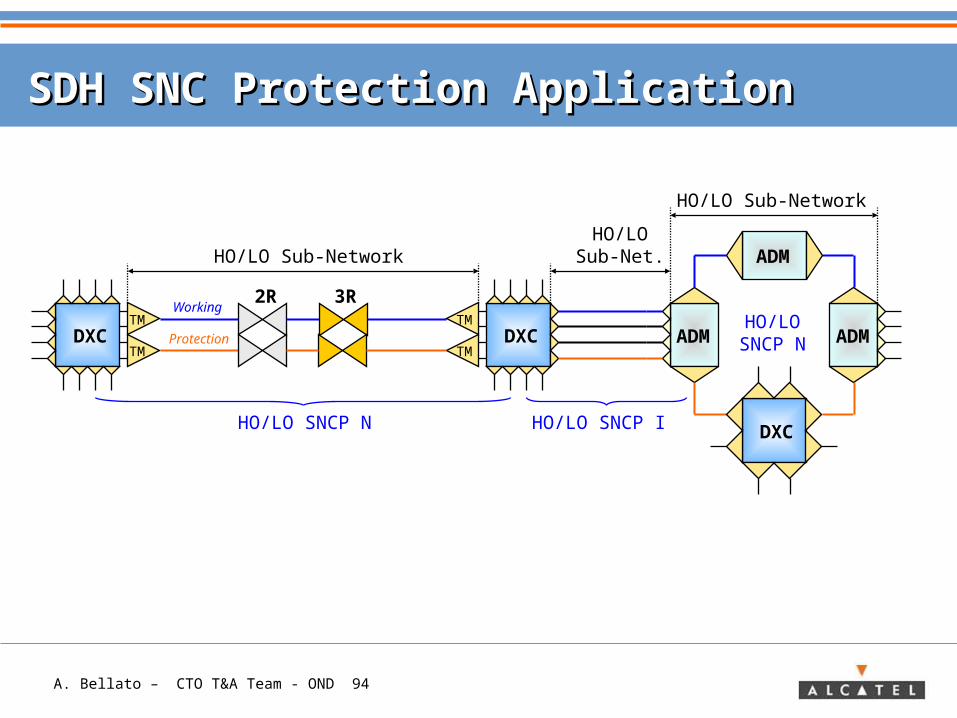
SDH SNC Protection ApplicationSDH SNC Protection Application
2R 3R
ADM
ADM ADM
HO/LO Sub-NetworkHO/LO
Sub-Net.
DXC
DXCTM
TMDXC
TM
TM
HO/LO SNCP N
HO/LOSNCP N
Working
Protection
HO/LO Sub-Network
HO/LO SNCP I
A. Bellato – CTO T&A Team - OND 95
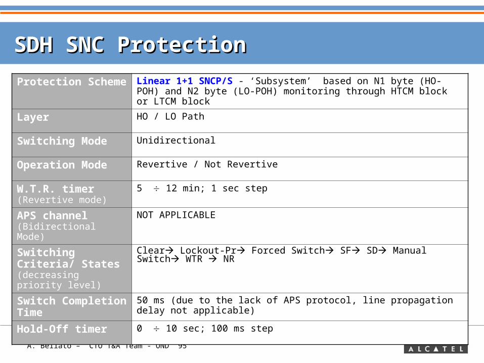
SDH SNC ProtectionSDH SNC Protection
Protection Scheme
Linear 1+1 SNCP/S - ‘Subsystem’ based on N1 byte (HO-POH) and N2 byte (LO-POH) monitoring through HTCM block or LTCM block
Layer HO / LO Path
Switching Mode Unidirectional
Operation Mode Revertive / Not Revertive
W.T.R. timer (Revertive mode)
5 12 min; 1 sec step
APS channel (Bidirectional Mode)
NOT APPLICABLE
Switching Criteria/ States (decreasing priority level)
Clear Lockout-Pr Forced Switch SF SD Manual Switch WTR NR
Switch Completion Time
50 ms (due to the lack of APS protocol, line propagation delay not applicable)
Hold-Off timer 0 10 sec; 100 ms step
A. Bellato – CTO T&A Team - OND 96
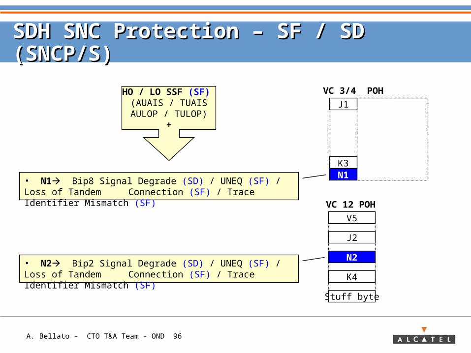
SDH SNC Protection – SF / SD (SNCP/S)SDH SNC Protection – SF / SD (SNCP/S)
VC 3/4 POH
V5
J2
N2
K4
Stuff byte
VC 12 POH
J1
K3N1
• N1 Bip8 Signal Degrade (SD) / UNEQ (SF) / Loss of Tandem Connection (SF) / Trace Identifier Mismatch (SF)
HO / LO SSF (SF) (AUAIS / TUAIS
AULOP / TULOP)+
• N2 Bip2 Signal Degrade (SD) / UNEQ (SF) / Loss of Tandem Connection (SF) / Trace Identifier Mismatch (SF)
A. Bellato – CTO T&A Team - OND 97
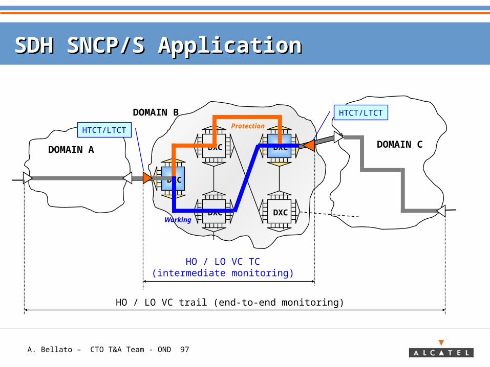
SDH SNCP/S ApplicationSDH SNCP/S Application
DXC
DXC DXC
DXC
DXC
DOMAIN A
DOMAIN B
DOMAIN C
Protection
Working
HTCT/LTCT
HTCT/LTCT
HO / LO VC TC(intermediate monitoring)
HO / LO VC trail (end-to-end monitoring)
A. Bellato – CTO T&A Team - OND 98
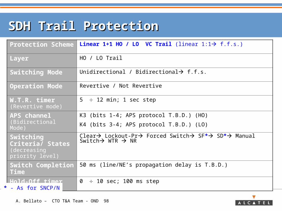
SDH Trail ProtectionSDH Trail ProtectionProtection Scheme
Linear 1+1 HO / LO VC Trail (linear 1:1 f.f.s.)
Layer HO / LO Trail
Switching Mode Unidirectional / Bidirectional f.f.s.
Operation Mode Revertive / Not Revertive
W.T.R. timer (Revertive mode)
5 12 min; 1 sec step
APS channel (Bidirectional Mode)
K3 (bits 1-4; APS protocol T.B.D.) (HO)
K4 (bits 3-4; APS protocol T.B.D.) (LO)
Switching Criteria/ States (decreasing priority level)
Clear Lockout-Pr Forced Switch SF* SD* Manual Switch WTR NR
Switch Completion Time
50 ms (line/NE’s propagation delay is T.B.D.)
Hold-Off timer 0 10 sec; 100 ms step
* - As for SNCP/N
A. Bellato – CTO T&A Team - OND 99
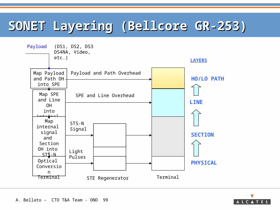
SONET Layering (Bellcore GR-253)SONET Layering (Bellcore GR-253)
Map Payloadand Path OH
into SPE
Map SPEand Line
OHinto
internal signalMap
internal signal and Section OH
into STS-N signal
Optical Conversion
STS-NSignal
Light Pulses
Payload and Path Overhead
SPE and Line Overhead
STE RegeneratorTerminal Terminal
PHYSICAL
SECTION
LINE
HO/LO PATH
LAYERS
Payload (DS1, DS2, DS3DS4NA, Video, etc.)
A. Bellato – CTO T&A Team - OND 100
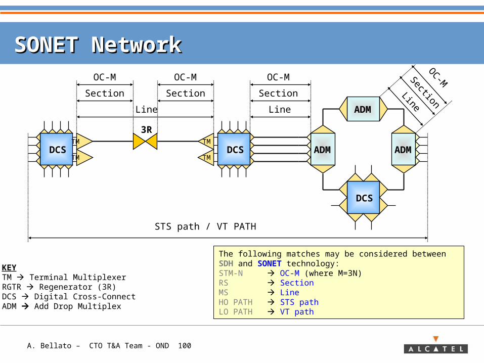
SONET NetworkSONET Network
3R
ADM
ADM ADM
Line
Section
OC-M OC-M
Section
Line
STS path / VT PATH
KEYTM Terminal MultiplexerRGTR Regenerator (3R)DCS Digital Cross-ConnectADM Add Drop Multiplex
DCS
DCSTM
TM
OC-MSection
Line
DCSTM
TM
Section
OC-M
The following matches may be considered between SDH and SONET technology:STM-N OC-M (where M=3N)RS SectionMS LineHO PATH STS pathLO PATH VT path
A. Bellato – CTO T&A Team - OND 101
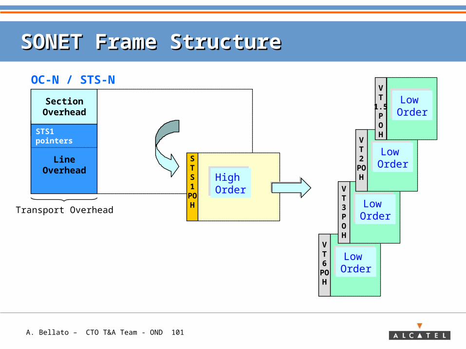
VT6POH
Low OrderLow Order
VT3POH
Low OrderLow Order
SONET Frame StructureSONET Frame Structure
SectionOverhead
LineOverhead
STS1POH
STS1 pointers
High OrderHigh Order
OC-N / STS-N
Transport Overhead
VT2POH
Low OrderLow Order
VT
1.5POH
Low OrderLow Order
A. Bellato – CTO T&A Team - OND 102
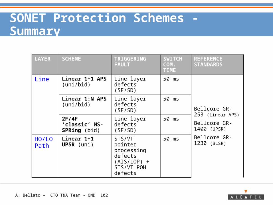
SONET Protection Schemes - Summary
LAYER SCHEME TRIGGERING FAULT
SWITCH COM. TIME
REFERENCE STANDARDS
Line Linear 1+1 APS (uni/bid)
Line layer defects (SF/SD)
50 ms
Bellcore GR-253 (linear APS)
Bellcore GR- 1400 (UPSR)
Bellcore GR-1230 (BLSR)
Linear 1:N APS (uni/bid)
Line layer defects (SF/SD)
50 ms
2F/4F ‘classic’ MS-SPRing (bid)
Line layer defects (SF/SD)
50 ms
HO/LO Path
Linear 1+1 UPSR (uni)
STS/VT pointer processing defects (AIS/LOP) + STS/VT POH defects
50 ms
A. Bellato – CTO T&A Team - OND 103
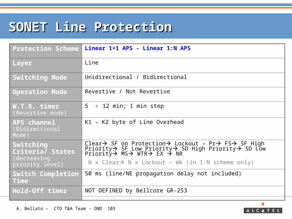
SONET Line Protection SONET Line Protection
Protection Scheme
Linear 1+1 APS - Linear 1:N APS
Layer Line
Switching Mode Unidirectional / Bidirectional
Operation Mode Revertive / Not Revertive
W.T.R. timer (Revertive mode)
5 12 min; 1 min step
APS channel (Bidirectional Mode)
K1 – K2 byte of Line Overhead
Switching Criteria/ States (decreasing priority level)
Clear SF on Protection Lockout – Pr FS SF High Priority SF Low Priority SD High Priority SD Low Priority MS WTR EX NR
N x Clear N x Lockout – Wk (in 1:N scheme only)
Switch Completion Time
50 ms (line/NE propagation delay not included)
Hold-Off timer NOT DEFINED by Bellcore GR-253
A. Bellato – CTO T&A Team - OND 104
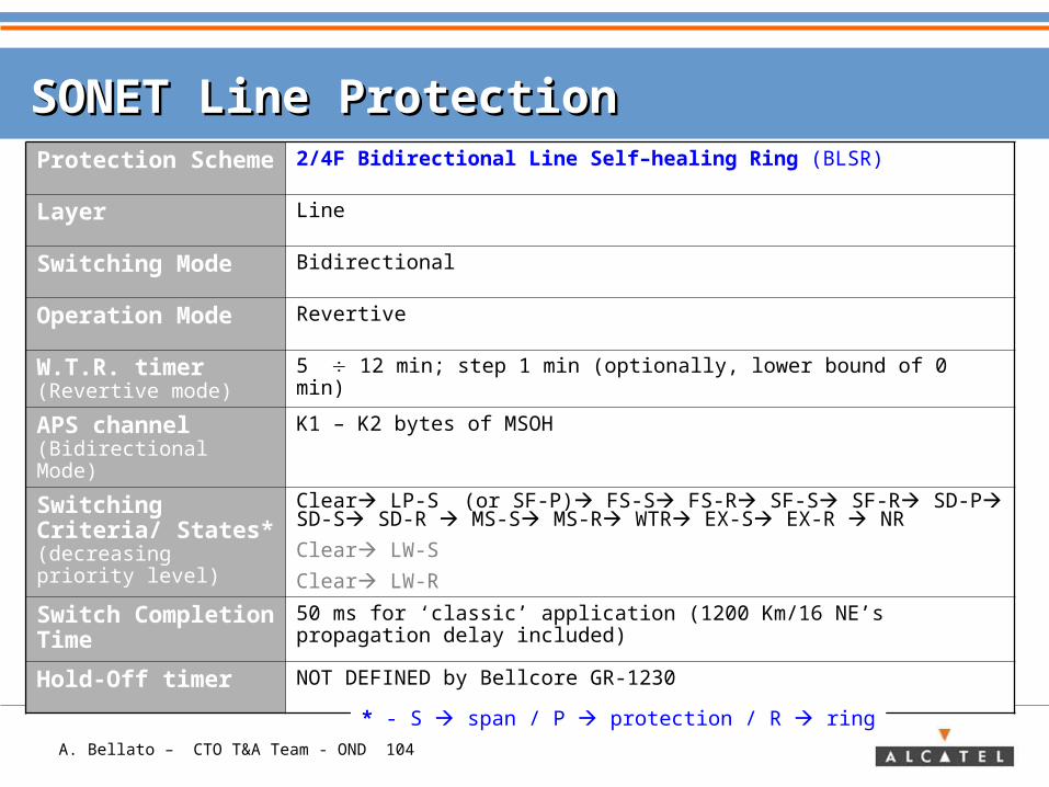
SONET Line Protection SONET Line Protection Protection Scheme
2/4F Bidirectional Line Self–healing Ring (BLSR)
Layer Line
Switching Mode Bidirectional
Operation Mode Revertive
W.T.R. timer (Revertive mode)
5 12 min; step 1 min (optionally, lower bound of 0 min)
APS channel (Bidirectional Mode)
K1 – K2 bytes of MSOH
Switching Criteria/ States* (decreasing priority level)
Clear LP-S (or SF-P) FS-S FS-R SF-S SF-R SD-P SD-S SD-R MS-S MS-R WTR EX-S EX-R NR
Clear LW-S
Clear LW-R
Switch Completion Time
50 ms for ‘classic’ application (1200 Km/16 NE’s propagation delay included)
Hold-Off timer NOT DEFINED by Bellcore GR-1230
* - S span / P protection / R ring
A. Bellato – CTO T&A Team - OND 105
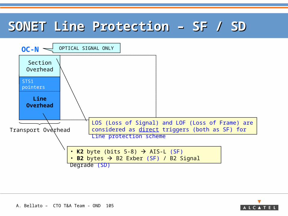
SONET Line Protection – SONET Line Protection – SF / SD SF / SD
SectionOverhead
LineOverhead
STS1 pointers
OC-N
Transport Overhead
• K2 byte (bits 5-8) AIS-L (SF)• B2 bytes B2 Exber (SF) / B2 Signal Degrade (SD)
LOS (Loss of Signal) and LOF (Loss of Frame) are considered as direct triggers (both as SF) for Line protection scheme
OPTICAL SIGNAL ONLY
A. Bellato – CTO T&A Team - OND 106
APS channel in SONET Line schemesAPS channel in SONET Line schemes
SectionOH
Pointers
OC-N
K1 K2
bits 1-4
Request Type Source Node ID
Destination Node ID Path
Bridge Status
SectionOH
Pointers
OC-N
K1 K2
LineOH
bits 1-4
Request Type Req. Ch. Id. Br. Ch. Id. (Bridge Status)
Arch. Mode
LineOH
A. Bellato – CTO T&A Team - OND 107
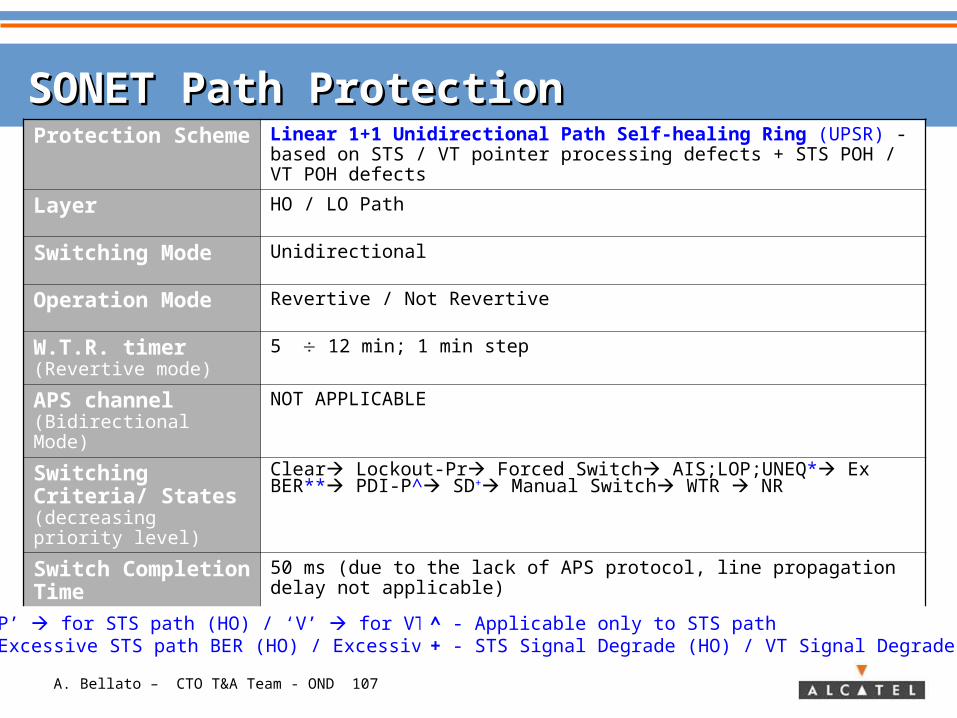
SONET Path ProtectionSONET Path ProtectionProtection Scheme
Linear 1+1 Unidirectional Path Self-healing Ring (UPSR) - based on STS / VT pointer processing defects + STS POH / VT POH defects
Layer HO / LO Path
Switching Mode Unidirectional
Operation Mode Revertive / Not Revertive
W.T.R. timer (Revertive mode)
5 12 min; 1 min step
APS channel (Bidirectional Mode)
NOT APPLICABLE
Switching Criteria/ States (decreasing priority level)
Clear Lockout-Pr Forced Switch AIS;LOP;UNEQ* Ex BER** PDI-P^ SD+ Manual Switch WTR NR
Switch Completion Time
50 ms (due to the lack of APS protocol, line propagation delay not applicable)
Hold-Off timer NOT DEFINED by Bellcore GR-1400
* - ‘P’ for STS path (HO) / ‘V’ for VT path (LO)** - Excessive STS path BER (HO) / Excessive VT path BER (LO)
^ - Applicable only to STS path+ - STS Signal Degrade (HO) / VT Signal Degrade (LO)
A. Bellato – CTO T&A Team - OND 108
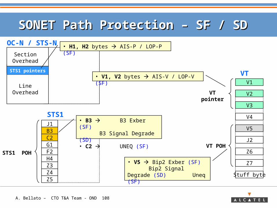
SONET Path Protection – SF / SD SONET Path Protection – SF / SD
V5
J2
Z6
Z7
Stuff byte
VT POH
• V5 Bip2 Exber (SF) Bip2 Signal Degrade
(SD) Uneq (SF)
STS1 POH
J1B3C2G1F2
Z4Z5
H4Z3
SectionOverhead
LineOverhead
OC-N / STS-N
STS1 pointers
• H1, H2 bytes AIS-P / LOP-P (SF)
V1
V2
V3
V4
VT pointer
VT
STS1
• V1, V2 bytes AIS-V / LOP-V (SF)
• B3 B3 Exber (SF)B3 Signal Degrade
(SD)• C2 UNEQ (SF)
A. Bellato – CTO T&A Team - OND 109
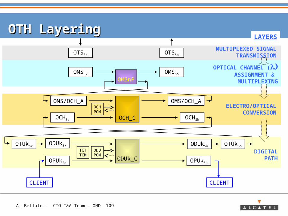
OTH LayeringOTH Layering
OMSSk
OCHSk
OCHPOM
OMSnP
OCH_C
ODUk_CDIGITAL
PATH
ELECTRO/OPTICALCONVERSION
OPTICAL CHANNEL (ASSIGNMENT & MULTIPLEXING
LAYERS
OTSSk
OCHSo
OMSSo
OTSSo
MULTIPLEXED SIGNALTRANSMISSION
OTUkSk ODUkSo OTUkSoODUPOM
ODUkSk
OPUkSkOPUkSo
CLIENT CLIENT
TCTTCM
OMS/OCH_A OMS/OCH_A
A. Bellato – CTO T&A Team - OND 110
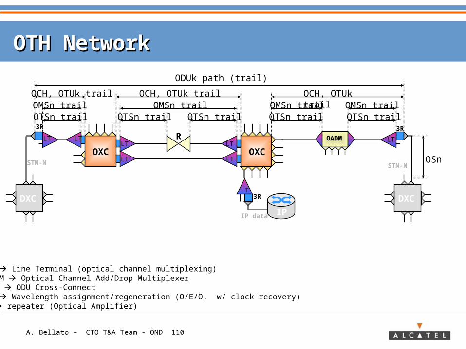
OTH NetworkOTH Network
3R
OADM
STM-N
OCH, OTUk trailOMSn trailOTSn trail
ODUk path (trail)
OXCLT
LTOXC
LT
LT
KEYLT Line Terminal (optical channel multiplexing)OADM Optical Channel Add/Drop MultiplexerOXC ODU Cross-Connect3R Wavelength assignment/regeneration (O/E/O, w/ clock recovery)R repeater (Optical Amplifier)
DXC
IP
LT
IP data
R
OMSn trailOTSn trail OTSn trail
OCH, OTUk trail
LT
3R
OCH, OTUk trail
LT
OMSn trailOTSn trail
LT
3R
OMSn trailOTSn trail
DXC
STM-N OSn
A. Bellato – CTO T&A Team - OND 111
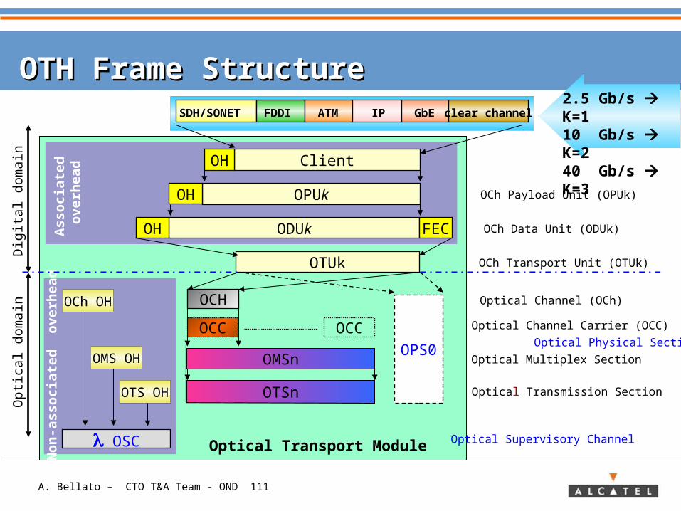
OTH Frame StructureOTH Frame Structure
Optical Transport Module
OPSn
OTUk
Optical Channel (OCh)
Optical Channel Carrier (OCC)
ODUk FECOH
OCh Transport Unit (OTUk)
OPUkOH
OCh Data Unit (ODUk)
ClientOH
OCh Payload Unit (OPUk)
Dig
ital dom
ain
Associa
ted
overh
ead
Optical Supervisory Channel OSC
Non
-associa
ted
overh
ead
OMSn
OTSn
Optical Multiplex Section
Optical Transmission Section
OPS0 Optical Physical Section
Op
tica
l d
om
ain
SDH/SONET
FDDI ATM IP GbE clear channel
OTS OH
OMS OH
OCh OH OCH
2.5 Gb/s K=1 10 Gb/s K=2 40 Gb/s K=3
OCC OCC
A. Bellato – CTO T&A Team - OND 112
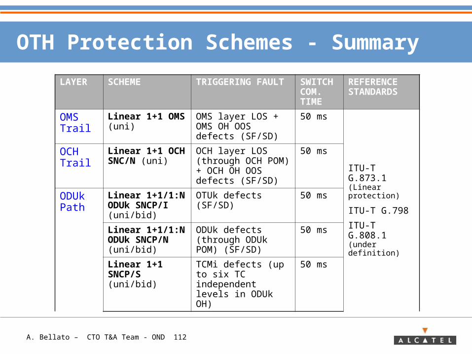
OTH Protection Schemes - Summary
LAYER SCHEME TRIGGERING FAULT
SWITCH COM. TIME
REFERENCE STANDARDS
OMS Trail
Linear 1+1 OMS (uni)
OMS layer LOS + OMS OH OOS defects (SF/SD)
50 ms
ITU-T G.873.1 (Linear protection)
ITU-T G.798
ITU-T G.808.1 (under definition)
OCH Trail
Linear 1+1 OCH SNC/N (uni)
OCH layer LOS (through OCH POM) + OCH OH OOS defects (SF/SD)
50 ms
ODUk Path
Linear 1+1/1:N ODUk SNCP/I (uni/bid)
OTUk defects (SF/SD)
50 ms
Linear 1+1/1:N ODUk SNCP/N (uni/bid)
ODUk defects (through ODUk POM) (SF/SD)
50 ms
Linear 1+1 SNCP/S (uni/bid)
TCMi defects (up to six TC independent levels in ODUk OH)
50 ms
A. Bellato – CTO T&A Team - OND 113
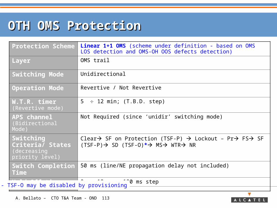
OTH OMS ProtectionOTH OMS Protection
Protection Scheme
Linear 1+1 OMS (scheme under definition - based on OMS LOS detection and OMS-OH OOS defects detection)
Layer OMS trail
Switching Mode Unidirectional
Operation Mode Revertive / Not Revertive
W.T.R. timer (Revertive mode)
5 12 min; (T.B.D. step)
APS channel (Bidirectional Mode)
Not Required (since ‘unidir’ switching mode)
Switching Criteria/ States (decreasing priority level)
Clear SF on Protection (TSF-P) Lockout – Pr FS SF (TSF-P) SD (TSF-O)* MS WTR NR
Switch Completion Time
50 ms (line/NE propagation delay not included)
Hold-Off timer 0 10 sec; 100 ms step
* - TSF-O may be disabled by provisioning
A. Bellato – CTO T&A Team - OND 114
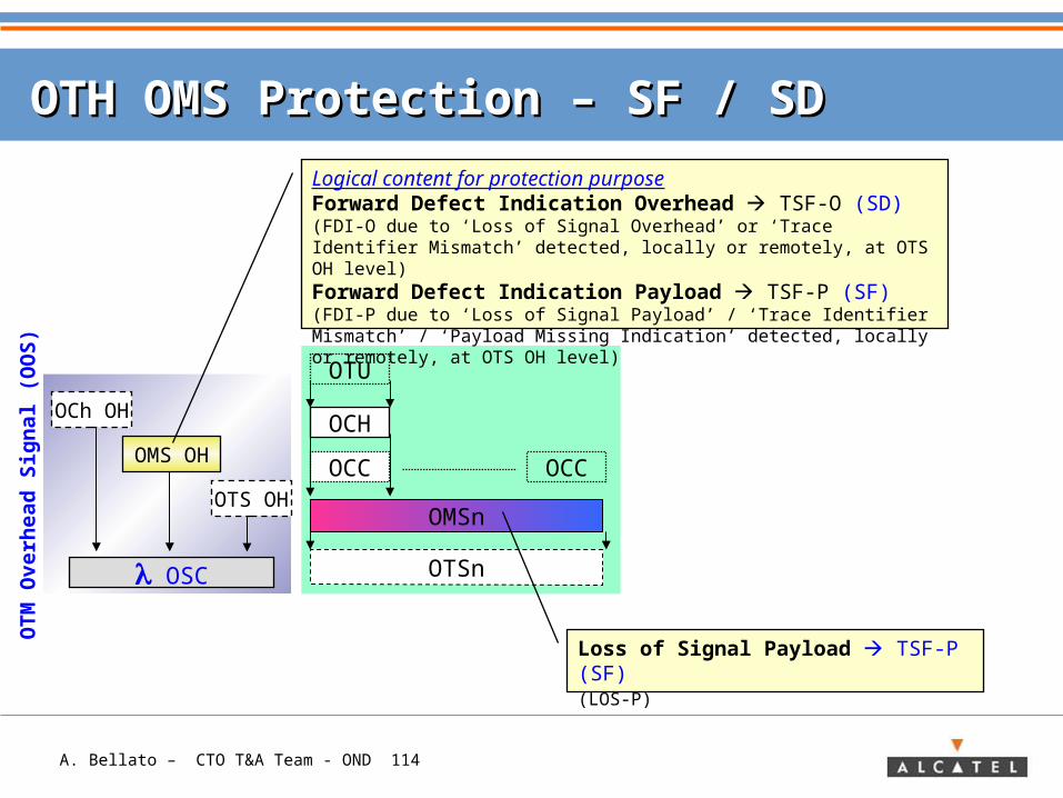
OTH OMS Protection – OTH OMS Protection – SF / SD SF / SD
OSC
OTM
Overh
ead
Sig
nal (O
OS
)
OTS OH
OMS OH
OCh OH
OPSnOMSn
OTSn
OCH
OCC OCC
OTU
Logical content for protection purposeForward Defect Indication Overhead TSF-O (SD)(FDI-O due to ‘Loss of Signal Overhead’ or ‘Trace Identifier Mismatch’ detected, locally or remotely, at OTS OH level)Forward Defect Indication Payload TSF-P (SF)(FDI-P due to ‘Loss of Signal Payload’ / ‘Trace Identifier Mismatch’ / ‘Payload Missing Indication’ detected, locally or remotely, at OTS OH level)
Loss of Signal Payload TSF-P (SF) (LOS-P)
A. Bellato – CTO T&A Team - OND 115
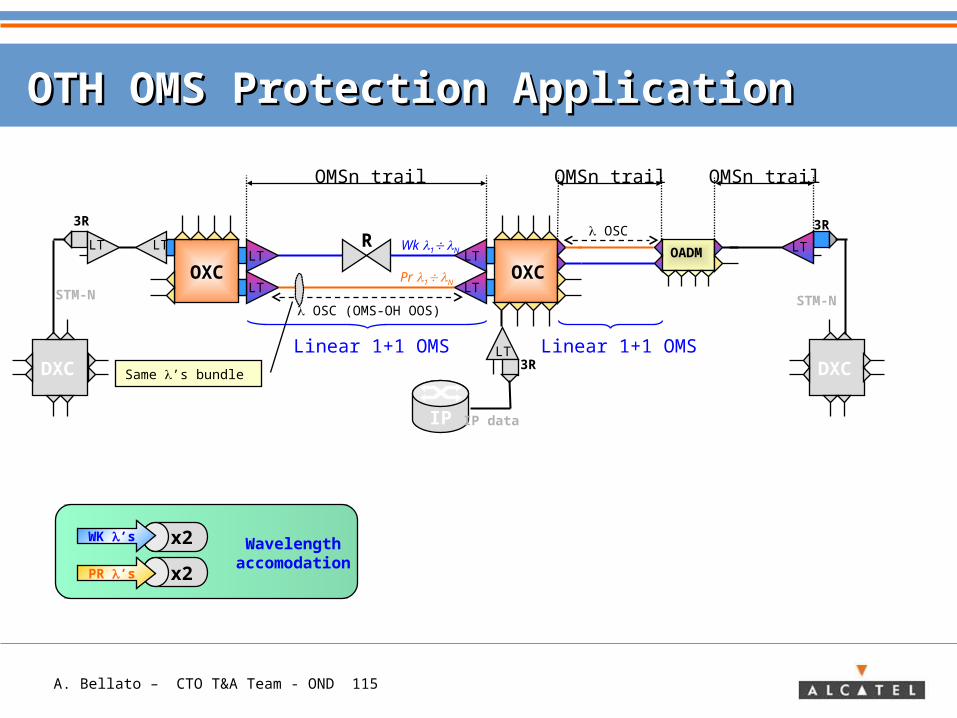
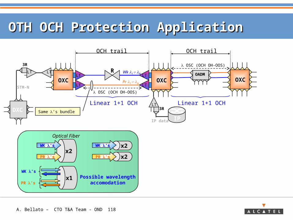
OTH OMS Protection ApplicationOTH OMS Protection Application
3R
OADM
STM-N
OMSn trail
OXCLT
LTOXC
LT
LT
DXC
IP
LT
IP data
R
OMSn trail
LT
3R
LT LT
3R
OMSn trail
DXC
STM-N
Linear 1+1 OMS
OSC (OMS-OH OOS)
Same ’s bundle
Wk 1 N
OSC
Linear 1+1 OMS
Pr 1 N
x2
x2
WK ’s
PR ’s
Wavelengthaccomodation
A. Bellato – CTO T&A Team - OND 116
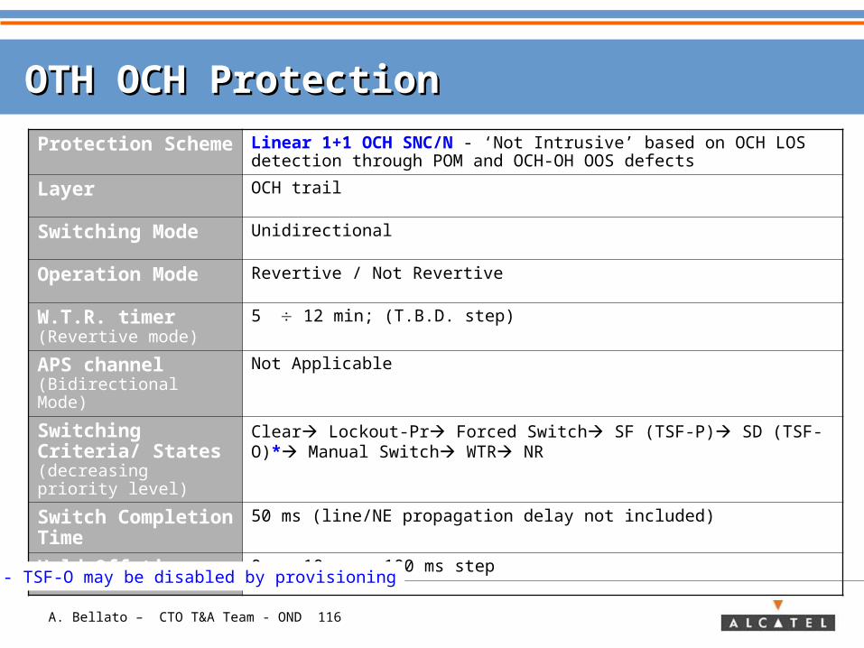
OTH OCH ProtectionOTH OCH Protection
Protection Scheme
Linear 1+1 OCH SNC/N - ‘Not Intrusive’ based on OCH LOS detection through POM and OCH-OH OOS defects
Layer OCH trail
Switching Mode Unidirectional
Operation Mode Revertive / Not Revertive
W.T.R. timer (Revertive mode)
5 12 min; (T.B.D. step)
APS channel (Bidirectional Mode)
Not Applicable
Switching Criteria/ States (decreasing priority level)
Clear Lockout-Pr Forced Switch SF (TSF-P) SD (TSF-O)* Manual Switch WTR NR
Switch Completion Time
50 ms (line/NE propagation delay not included)
Hold-Off timer 0 10 sec; 100 ms step
* - TSF-O may be disabled by provisioning
A. Bellato – CTO T&A Team - OND 117
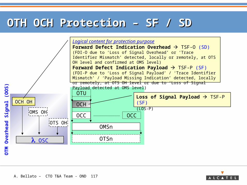
OTH OCH Protection – OTH OCH Protection – SF / SD SF / SD
OSC
OTM
Overh
ead
Sig
nal (O
OS
)
OTS OH
OCH OH
OMS OH
OPSnOMSn
OTSn
OCC OCC
OTU
Logical content for protection purposeForward Defect Indication Overhead TSF-O (SD)(FDI-O due to ‘Loss of Signal Overhead’ or ‘Trace Identifier Mismatch’ detected, locally or remotely, at OTS OH level and confirmed at OMS level)Forward Defect Indication Payload TSF-P (SF)(FDI-P due to ‘Loss of Signal Payload’ / ‘Trace Identifier Mismatch’ / ‘Payload Missing Indication’ detected, locally or remotely, at OTS OH level or due to ‘Loss of Signal Payload detected at OMS level)
OCHLoss of Signal Payload TSF-P (SF) (LOS-P)
A. Bellato – CTO T&A Team - OND 118
OTH OCH Protection ApplicationOTH OCH Protection Application
3R
OADM
STM-N
OCH trail
OXCLT
LTOXC
LT
LT
DXC
IP
LT
IP data
R
OCH trail
LT
3R
LT
Linear 1+1 OCH
OSC (OCH OH-OOS)
Same ’s bundle
OXC
Linear 1+1 OCH
Wk 1 N
Pr 1 N
OSC (OCH OH-OOS)
x2
x2x2
WK ’s
PR ’s
WK ’s
PR ’s
x1WK ’s
PR ’s
Optical Fiber
Possible wavelengthaccomodation
A. Bellato – CTO T&A Team - OND 119
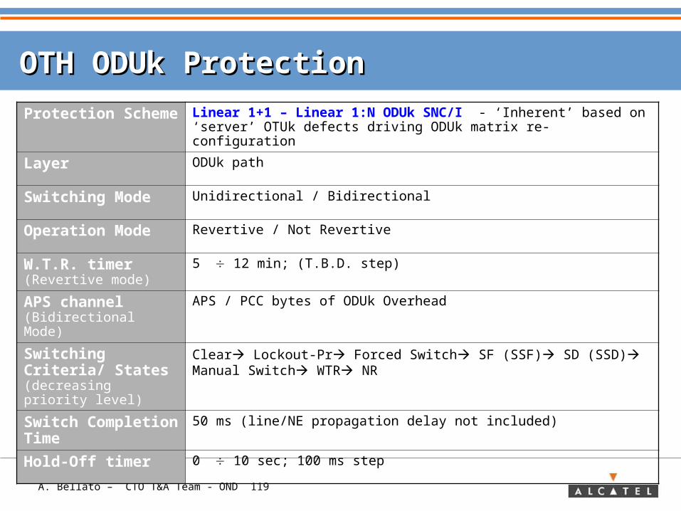
OTH ODUk ProtectionOTH ODUk Protection
Protection Scheme
Linear 1+1 – Linear 1:N ODUk SNC/I - ‘Inherent’ based on ‘server’ OTUk defects driving ODUk matrix re-configuration
Layer ODUk path
Switching Mode Unidirectional / Bidirectional
Operation Mode Revertive / Not Revertive
W.T.R. timer (Revertive mode)
5 12 min; (T.B.D. step)
APS channel (Bidirectional Mode)
APS / PCC bytes of ODUk Overhead
Switching Criteria/ States (decreasing priority level)
Clear Lockout-Pr Forced Switch SF (SSF) SD (SSD) Manual Switch WTR NR
Switch Completion Time
50 ms (line/NE propagation delay not included)
Hold-Off timer 0 10 sec; 100 ms step
A. Bellato – CTO T&A Team - OND 120
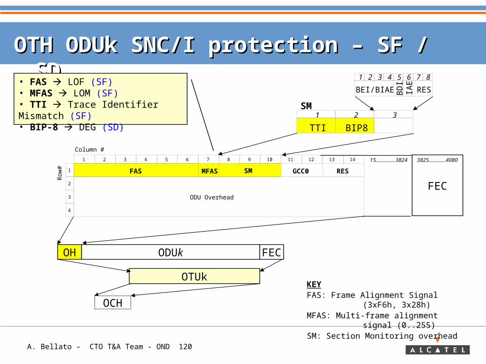
OTH ODUk SNC/I protection – OTH ODUk SNC/I protection – SF / SD SF / SD
OTUk
ODUk FECOH
OCH
FEC
1
2
3
4
1 2 3 4 5 6 7 8
FAS
Column #
MFAS SM
9 10 11 12 13 14
Row
#
ODU Overhead
RESGCC0
• FAS LOF (SF)• MFAS LOM (SF)• TTI Trace Identifier Mismatch (SF)• BIP-8 DEG (SD) TTI BIP8
1 2 3SM
BEI/BIAE BD
I
RES
1 2 3 4 5 6 7 8
IAE
KEYFAS: Frame Alignment Signal (3xF6h,
3x28h)MFAS: Multi-frame alignment signal
(0..255)SM: Section Monitoring overhead
15…………..3824 3825…………4080

A. Bellato – CTO T&A Team - OND 121
APS channel in OTN linear protectionAPS channel in OTN linear protection
Request Type Req. Ch. Id. Br. Ch. Id. (Bridge Status)
Arch. Mode
1
2
3
4
1 2 3 4 5 6 7
RES
Row
#
EXP
TCMACT TCM6
TCM3 TCM2 TCM1
GCC1 GCC2 RES
FTFL
PM
OPUkoverhead
Frame Alignment Overhead
APS/PCC
8 10 11 12 13 14 15
OTUk Overhead
169
TCM5 TCM4
Bytes 5-6-7 Automatic Protection Switching / Protection Communication ChannelByte 8 reserved for future use
ODUk
A. Bellato – CTO T&A Team - OND 122
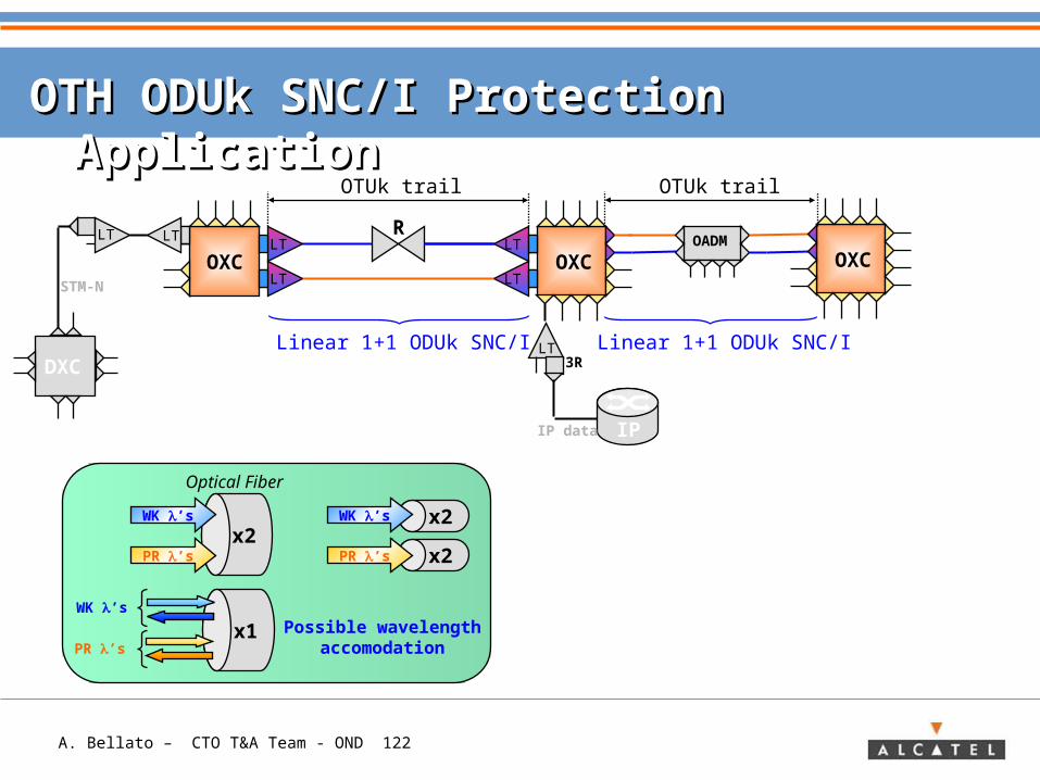
OTH ODUk SNC/I Protection ApplicationOTH ODUk SNC/I Protection Application
OADM
OXCLT
LTOXC
LT
LT
IP
LT
IP data
R
OTUk trail
3RLinear 1+1 ODUk SNC/I
OXCSTM-N
DXC
LT LT
x2
x2x2
WK ’s
PR ’s
WK ’s
PR ’s
x1WK ’s
PR ’s
Optical Fiber
Possible wavelengthaccomodation
OTUk trail
Linear 1+1 ODUk SNC/I
A. Bellato – CTO T&A Team - OND 123
OTH ODUk ProtectionOTH ODUk Protection
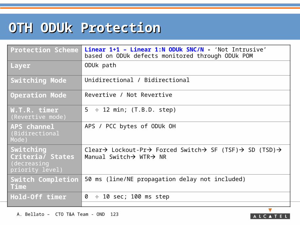
Protection Scheme
Linear 1+1 – Linear 1:N ODUk SNC/N - ‘Not Intrusive’ based on ODUk defects monitored through ODUk POM
Layer ODUk path
Switching Mode Unidirectional / Bidirectional
Operation Mode Revertive / Not Revertive
W.T.R. timer (Revertive mode)
5 12 min; (T.B.D. step)
APS channel (Bidirectional Mode)
APS / PCC bytes of ODUk OH
Switching Criteria/ States (decreasing priority level)
Clear Lockout-Pr Forced Switch SF (TSF) SD (TSD) Manual Switch WTR NR
Switch Completion Time
50 ms (line/NE propagation delay not included)
Hold-Off timer 0 10 sec; 100 ms step
A. Bellato – CTO T&A Team - OND 124
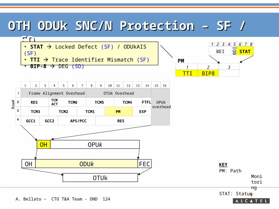
OTH ODUk SNC/N Protection – OTH ODUk SNC/N Protection – SF / SD SF / SD
1
2
3
4
1 2 3 4 5 6 7
RES
Row
#
EXP
TCMACT TCM6
TCM3 TCM2 TCM1
GCC1 GCC2 RES
FTFL
PM
OPUkoverhead
Frame Alignment Overhead
APS/PCC
OPUkOH
OTUk
ODUk FECOH
• STAT Locked Defect (SF) / ODUkAIS (SF)• TTI Trace Identifier Mismatch (SF)• BIP-8 DEG (SD)
TTI BIP81 2 3
PM
BEI BD
I
STAT
1 2 3 4 5 6 7 8
8 10 11 12 13 14 15
OTUk Overhead
169
TCM5 TCM4
KEYPM: Path
Monitoring
STAT: Status
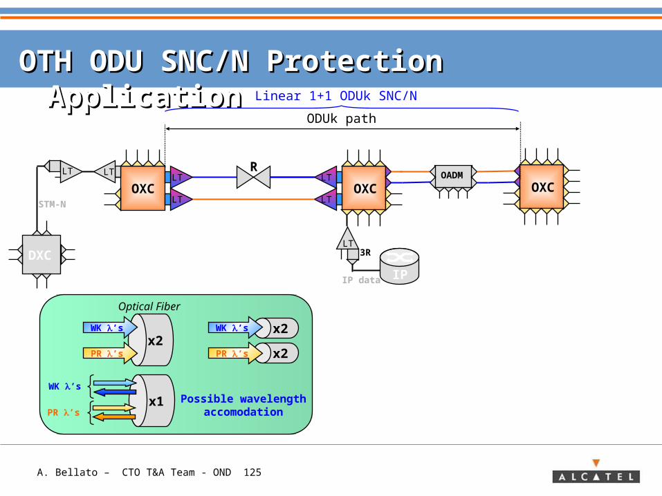
A. Bellato – CTO T&A Team - OND 125
OTH ODU SNC/N Protection ApplicationOTH ODU SNC/N Protection Application
OADM
ODUk path
OXCLT
LTOXC
LT
LT
IP
LT
IP data
R
3R
OXCSTM-N
DXC
LT LT
Linear 1+1 ODUk SNC/N
x2
x2x2
WK ’s
PR ’s
WK ’s
PR ’s
x1WK ’s
PR ’s
Optical Fiber
Possible wavelengthaccomodation
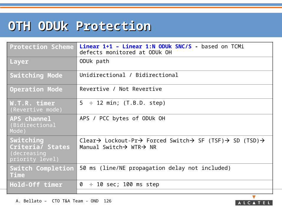
A. Bellato – CTO T&A Team - OND 126
OTH ODUk ProtectionOTH ODUk Protection
Protection Scheme
Linear 1+1 – Linear 1:N ODUk SNC/S - based on TCMi defects monitored at ODUk OH
Layer ODUk path
Switching Mode Unidirectional / Bidirectional
Operation Mode Revertive / Not Revertive
W.T.R. timer (Revertive mode)
5 12 min; (T.B.D. step)
APS channel (Bidirectional Mode)
APS / PCC bytes of ODUk OH
Switching Criteria/ States (decreasing priority level)
Clear Lockout-Pr Forced Switch SF (TSF) SD (TSD) Manual Switch WTR NR
Switch Completion Time
50 ms (line/NE propagation delay not included)
Hold-Off timer 0 10 sec; 100 ms step
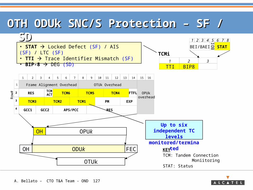
A. Bellato – CTO T&A Team - OND 127
OTH ODUk SNC/S Protection – OTH ODUk SNC/S Protection – SF / SD SF / SD
1
2
3
4
1 2 3 4 5 6 7
RES
Row
#
EXP
TCMACT TCM6
TCM3 TCM2 TCM1
GCC1 GCC2 RES
FTFL
PM
OPUkoverhead
Frame Alignment Overhead
APS/PCC
OPUkOH
OTUk
ODUk FECOH
• STAT Locked Defect (SF) / AIS (SF) / LTC (SF)• TTI Trace Identifier Mismatch (SF)• BIP-8 DEG (SD) TTI BIP8
1 2 3
TCMi
BEI/BAEI BD
I
STAT
1 2 3 4 5 6 7 8
8 10 11 12 13 14 15
OTUk Overhead
169
TCM5 TCM4
KEYTCM: Tandem Connection MoniitoringSTAT: Status
Up to six independent TC
levels monitored/termin
ated
A. Bellato – CTO T&A Team - OND 128
OTH ODUk SNC/S Protection ApplicationOTH ODUk SNC/S Protection Application
Operator A
Operator B
User
Working
Protection
End-to-End path supervision (PM)
User QoS supervision (TCM1)
User
Border of the OTNClient mapping into ODU
Border of the OTNClient mapping into ODU
TCM3 trail
Linear 1+1 ODUk SNC/S (B)
TCM2 trail
Linear 1+1 ODUk SNC/S (A)