Embed Size (px)
Citation preview
Transport LayerTCP and UDP
CT542
Content
• Transport layer services provided to upper layers• Transport service protocols• Berkley Sockets• An Example of Socket Programming
– Internet file server
• Elements of transport protocols– Adressing, establishing and releasing a connection
• Transport layer protocols– UDP
• UDP segment header• Remote Procedure Call
– TCP• Service model• TCP Protocol • The TCP Segment Header• TCP Connection Establishment• TCP Connection Release• TCP Connection Management Modeling• TCP Transmission Policy• TCP Congestion Control• TCP Timer Management
• Wireless TCP and UDP• Additional Slides
Services provided to the upper layer
– Provides a seamless interface between the Application layer and the Network layer
– The heart of the communications system– Two types:
• Connection oriented transport service• Connectionless transport service
– Key function is of isolating the upper layers from the technology, design and imperfections of the subnet (network layer)
– Allows applications to talk to each other without knowing about
• The underlying network• Physical links between nodes

Network, transport and application layers

TPDU
• Transport Packet Data Unit are sent from transport entity to transport entity
• TPDUs are contained in packets (exchanged by network layer)
• Packets are contained in frames (exchanged by the data link layer)
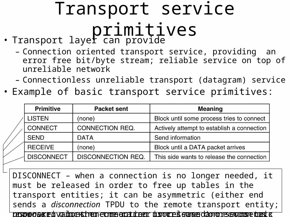
Transport service primitives• Transport layer can provide
– Connection oriented transport service, providing an error free bit/byte stream; reliable service on top of unreliable network
– Connectionless unreliable transport (datagram) service
• Example of basic transport service primitives:
LISTEN – in a client server application, the server executes this primitive, blocking the server until a client turns upCONNECT – when a client wants to talk to the server, it executes this primitive; the transport entity caries out this primitive (by sending a connection packet request to the server and waiting for a connection accepted response), blocking
the caller until the connection is established.
SEND/RECEIVE primitives can be used to exchange data after the connection has been established; either party could do (blocking) RECEIVE to wait for the other party to do SEND; when the TPDU arrives, the receiver is unblocked, does the required processing and sends back a reply
DISCONNECT – when a connection is no longer needed, it must be released in order to free up tables in the transport entities; it can be asymmetric (either end sends a disconnection TPDU to the remote transport entity; upon arrival, the connection is released) or symmetric (each direction is closed separately)
FSM modeling
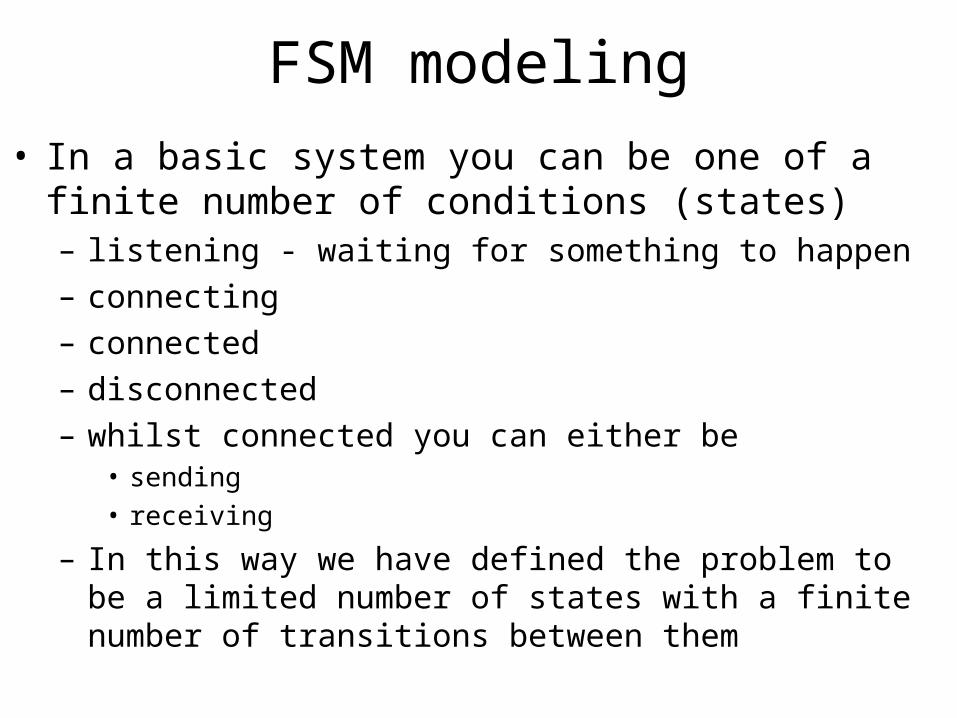
• In a basic system you can be one of a finite number of conditions (states)– listening - waiting for something to happen
– connecting
– connected
– disconnected
– whilst connected you can either be • sending
• receiving
– In this way we have defined the problem to be a limited number of states with a finite number of transitions between them
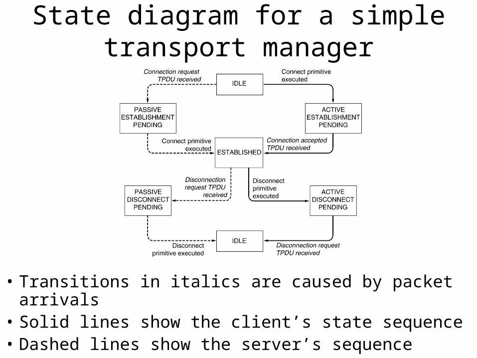
State diagram for a simple transport manager
• Transitions in italics are caused by packet arrivals• Solid lines show the client’s state sequence• Dashed lines show the server’s sequence
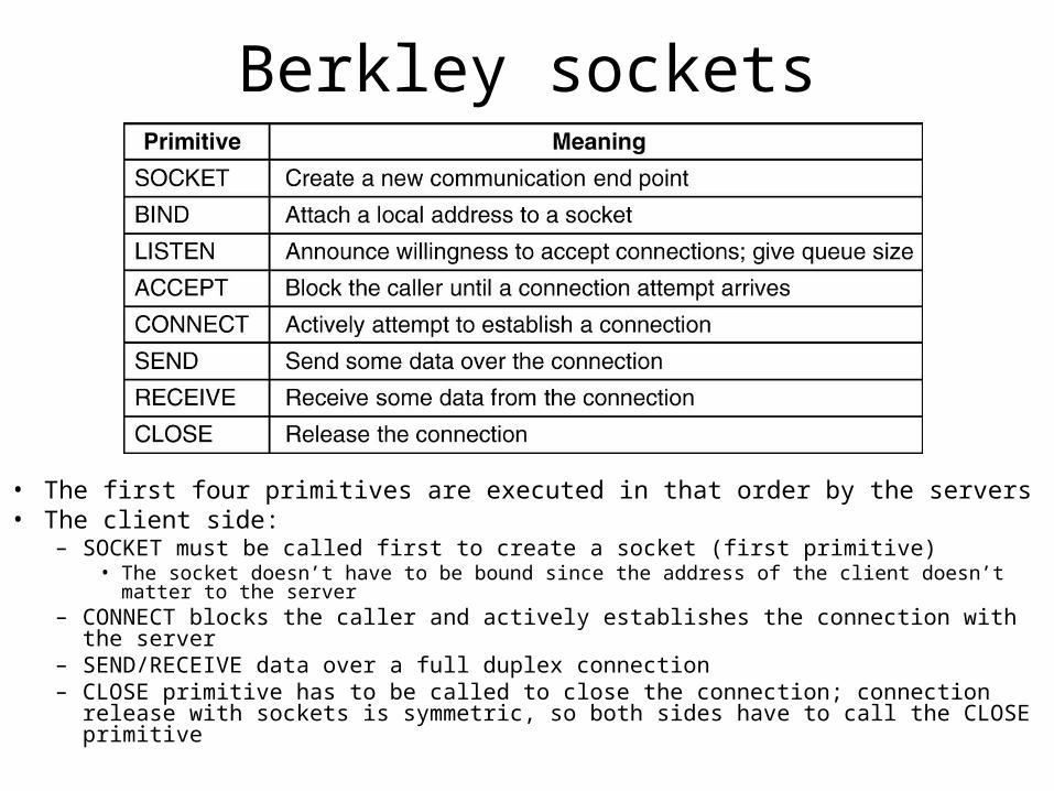
Berkley sockets
• The first four primitives are executed in that order by the servers• The client side:
– SOCKET must be called first to create a socket (first primitive)• The socket doesn’t have to be bound since the address of the client doesn’t matter to the server
– CONNECT blocks the caller and actively establishes the connection with the server– SEND/RECEIVE data over a full duplex connection– CLOSE primitive has to be called to close the connection; connection release with
sockets is symmetric, so both sides have to call the CLOSE primitive
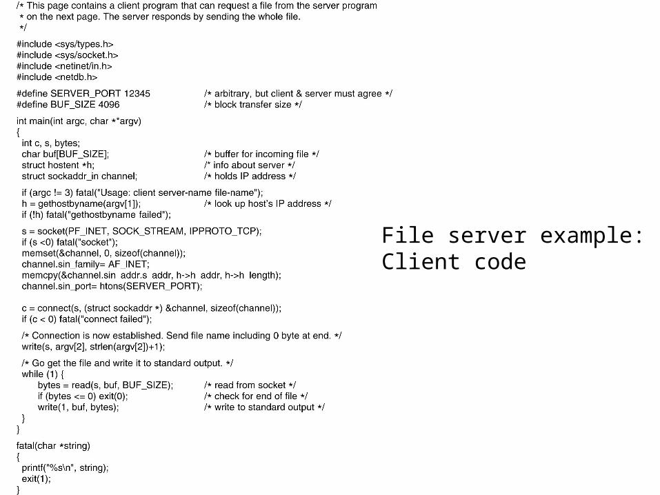
File server example:Client code
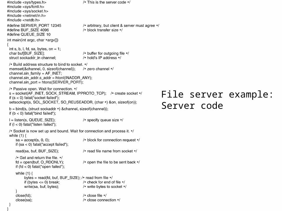
File server example:Server code
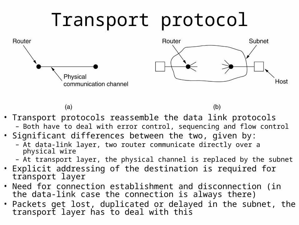
Transport protocol
• Transport protocols reassemble the data link protocols– Both have to deal with error control, sequencing and flow control
• Significant differences between the two, given by:– At data-link layer, two router communicate directly over a physical wire– At transport layer, the physical channel is replaced by the subnet
• Explicit addressing of the destination is required for transport layer• Need for connection establishment and disconnection (in the data-link
case the connection is always there)• Packets get lost, duplicated or delayed in the subnet, the transport
layer has to deal with this
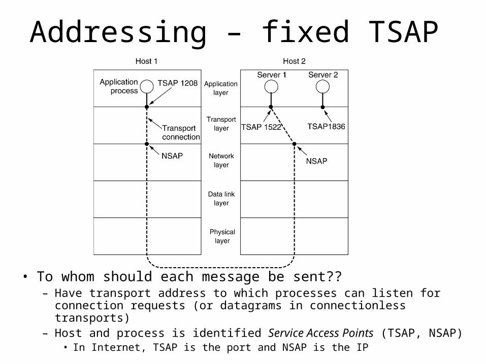
Addressing – fixed TSAP
• To whom should each message be sent??– Have transport address to which processes can listen for connection requests
(or datagrams in connectionless transports)– Host and process is identified Service Access Points (TSAP, NSAP)
• In Internet, TSAP is the port and NSAP is the IP
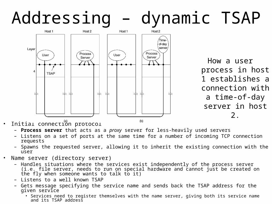
Addressing – dynamic TSAP
• Initial connection protocol– Process server that acts as a proxy server for less-heavily used servers– Listens on a set of ports at the same time for a number of incoming TCP connection requests– Spawns the requested server, allowing it to inherit the existing connection with the user
• Name server (directory server)– Handles situations where the services exist independently of the process server (i.e. file server, needs
to run on special hardware and cannot just be created on the fly when someone wants to talk to it)– Listens to a well known TSAP– Gets message specifying the service name and sends back the TSAP address for the given service
• Services need to register themselves with the name server, giving both its service name and its TSAP address
How a user process in host 1 establishes a connection with a
time-of-day server in host 2.
Establishing a connection
• When a communication link is made over a network (internet) problems can arise:– The network can lose, store and duplicate packets
• Use case scenario:– User establishes a connection with a bank, instructs the bank to transfer large
amount of money, closes connection
– The network delivers a delayed set of packets, in same sequence, getting the bank to perform another transfer
• Deal with duplicated packets
• There way handshake to establish a connection
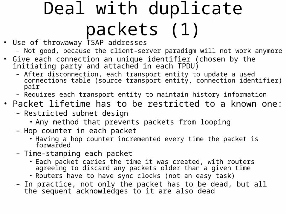
Deal with duplicate packets (1)• Use of throwaway TSAP addresses
– Not good, because the client-server paradigm will not work anymore• Give each connection an unique identifier (chosen by the initiating party and
attached in each TPDU)– After disconnection, each transport entity to update a used connections table (source
transport entity, connection identifier) pair– Requires each transport entity to maintain history information
• Packet lifetime has to be restricted to a known one:– Restricted subnet design
• Any method that prevents packets from looping– Hop counter in each packet
• Having a hop counter incremented every time the packet is forwarded– Time-stamping each packet
• Each packet caries the time it was created, with routers agreeing to discard any packets older than a given time
• Routers have to have sync clocks (not an easy task)– In practice, not only the packet has to be dead, but all the sequent acknowledges
to it are also dead
Deal with duplicate packets (2)
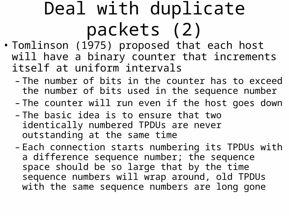
• Tomlinson (1975) proposed that each host will have a binary counter that increments itself at uniform intervals– The number of bits in the counter has to exceed the
number of bits used in the sequence number– The counter will run even if the host goes down– The basic idea is to ensure that two identically numbered
TPDUs are never outstanding at the same time– Each connection starts numbering its TPDUs with a
difference sequence number; the sequence space should be so large that by the time sequence numbers will wrap around, old TPDUs with the same sequence numbers are long gone
Connection Establishment
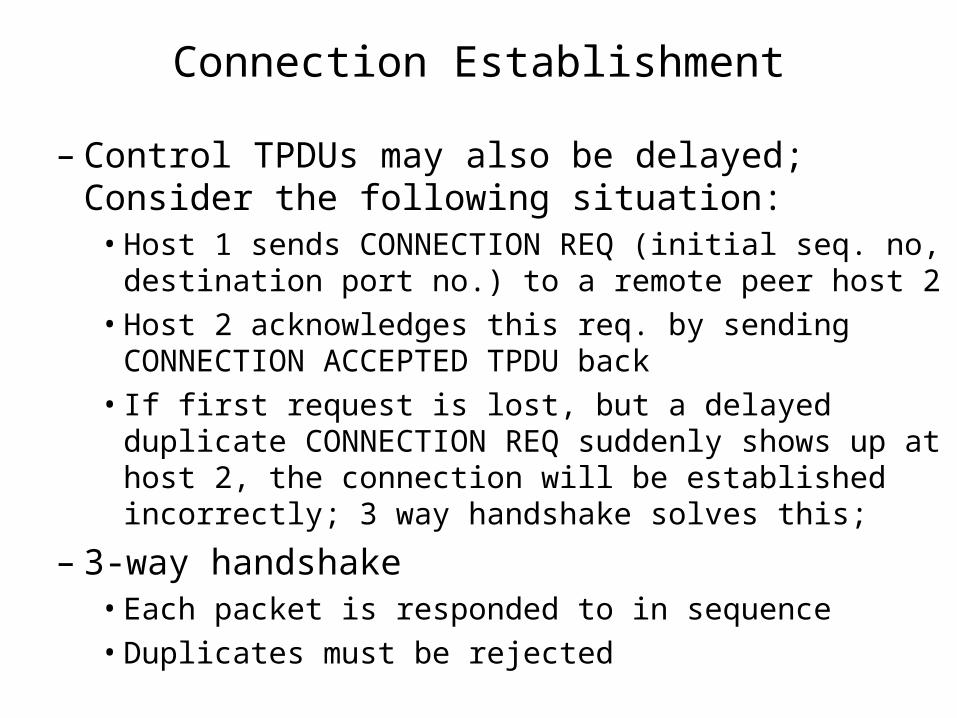
– Control TPDUs may also be delayed; Consider the following situation:
• Host 1 sends CONNECTION REQ (initial seq. no, destination port no.) to a remote peer host 2
• Host 2 acknowledges this req. by sending CONNECTION ACCEPTED TPDU back
• If first request is lost, but a delayed duplicate CONNECTION REQ suddenly shows up at host 2, the connection will be established incorrectly; 3 way handshake solves this;
– 3-way handshake• Each packet is responded to in sequence
• Duplicates must be rejected
Three way handshake
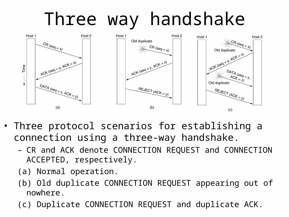
• Three protocol scenarios for establishing a connection using a three-way handshake. – CR and ACK denote CONNECTION REQUEST and CONNECTION
ACCEPTED, respectively.(a) Normal operation. (b) Old duplicate CONNECTION REQUEST appearing out of
nowhere. (c) Duplicate CONNECTION REQUEST and duplicate ACK.
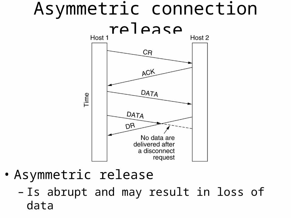
Asymmetric connection release
• Asymmetric release– Is abrupt and may result in loss of data
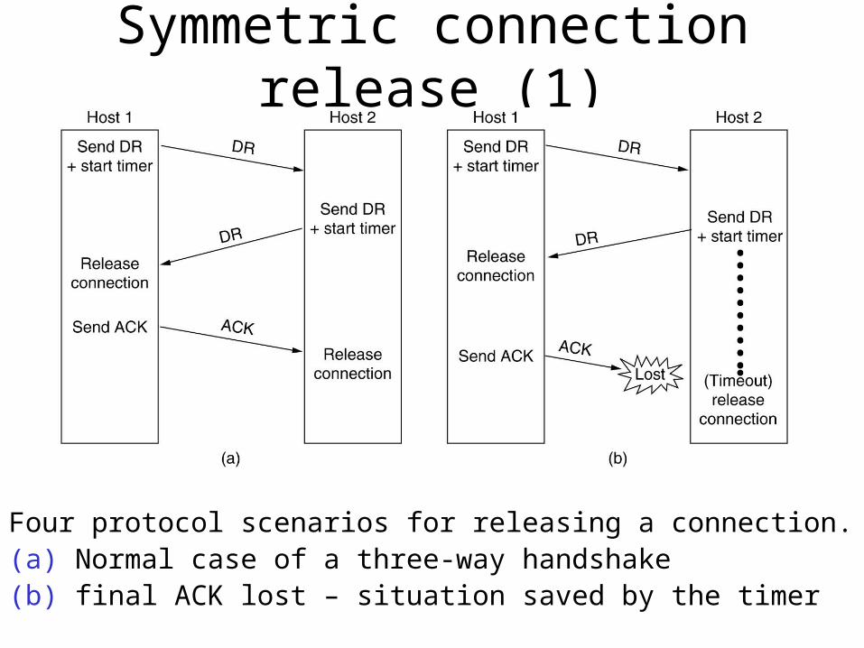
Symmetric connection release (1)
Four protocol scenarios for releasing a connection. (a) Normal case of a three-way handshake(b) final ACK lost – situation saved by the timer
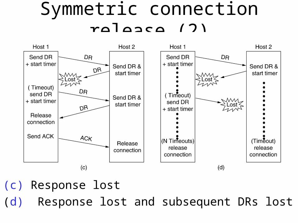
Symmetric connection release (2)
(c) Response lost
(d) Response lost and subsequent DRs lost
TCP/IP transport layer
• Two end-end protocols– TCP - Transmission Control Protocol
• connection oriented (either real or virtual)
• fragments a message for sending
• combines the message on receipt
– UDP - User Datagram Protocol• connection less - unreliable
• flow control etc provided by application
• client server application
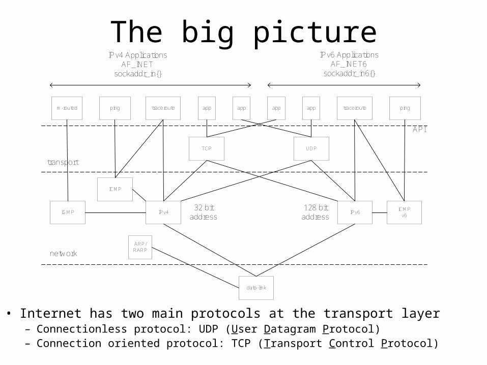
The big picture
• Internet has two main protocols at the transport layer– Connectionless protocol: UDP (User Datagram Protocol)– Connection oriented protocol: TCP (Transport Control Protocol)
m-routed ping traceroute app app app app traceroute ping
IPv4 ApplicationsAF_INET
sockaddr_in{}
IPv6 ApplicationsAF_INET6
sockaddr_in6{}
TCP UDP
IPv4 IPv632 bit
address128 bit
addressICMP
v6
ICMP
ARP/RARP
data-link
IGMP
API
transport
network
User Datagram Protocol• Simple transport layer protocol described in RFC 768, in
essence just a IP datagram with a short header• Provides a way to send encapsulated raw IP datagrams
without having to establish a connection– The application writes a datagram to a UDP socket, which is
encapsulated as either IPv4 or IPv6 datagram that is sent to the destination; there is no guarantee that UDP datagram ever reaches its final destination
– Many client-server application that have one request – one response use UDP
• Each UDP datagram has a length; if a UDP datagram reaches its final destination correctly, then the length of the datagram is passed onto the receiving application
• UDP provides a connectionless service as there is no need for a long term relation-ship between a client and the server
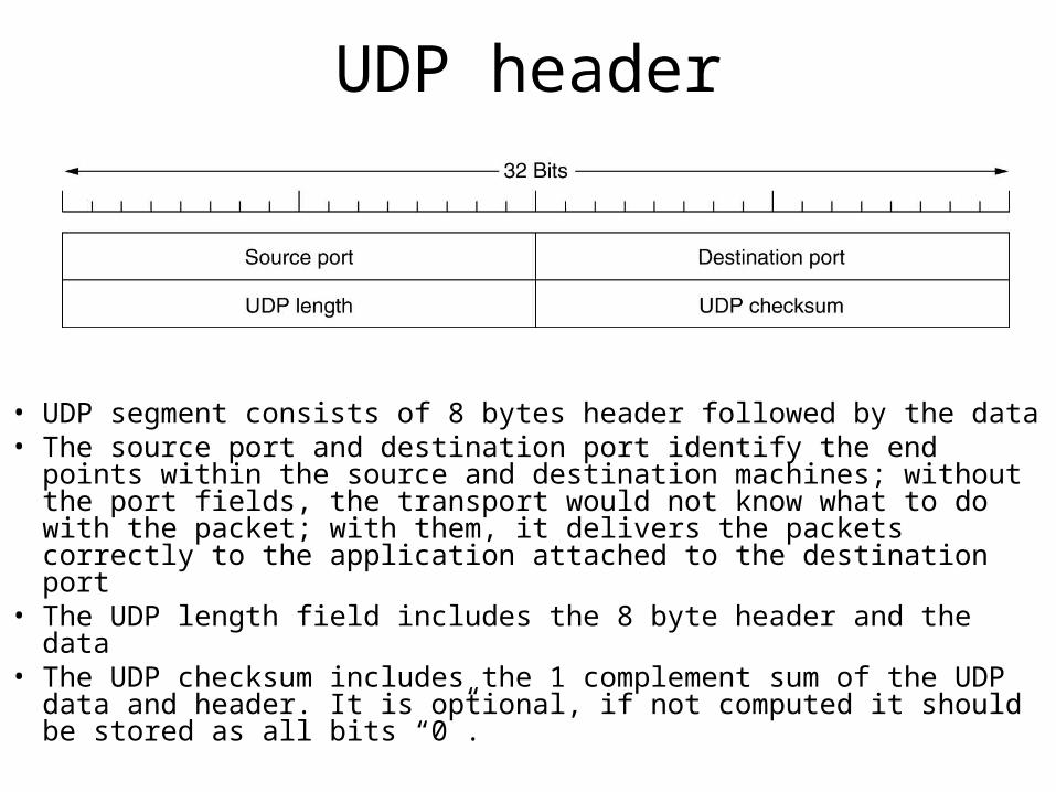
UDP header
• UDP segment consists of 8 bytes header followed by the data• The source port and destination port identify the end points within the
source and destination machines; without the port fields, the transport would not know what to do with the packet; with them, it delivers the packets correctly to the application attached to the destination port
• The UDP length field includes the 8 byte header and the data• The UDP checksum includes the 1 complement sum of the UDP data
and header. It is optional, if not computed it should be stored as all bits “0”.
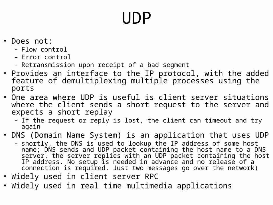
UDP• Does not:
– Flow control– Error control– Retransmission upon receipt of a bad segment
• Provides an interface to the IP protocol, with the added feature of demultiplexing multiple processes using the ports
• One area where UDP is useful is client server situations where the client sends a short request to the server and expects a short replay– If the request or reply is lost, the client can timeout and try again
• DNS (Domain Name System) is an application that uses UDP – shortly, the DNS is used to lookup the IP address of some host name; DNS
sends and UDP packet containing the host name to a DNS server, the server replies with an UDP packet containing the host IP address. No setup is needed in advance and no release of a connection is required. Just two messages go over the network)
• Widely used in client server RPC• Widely used in real time multimedia applications
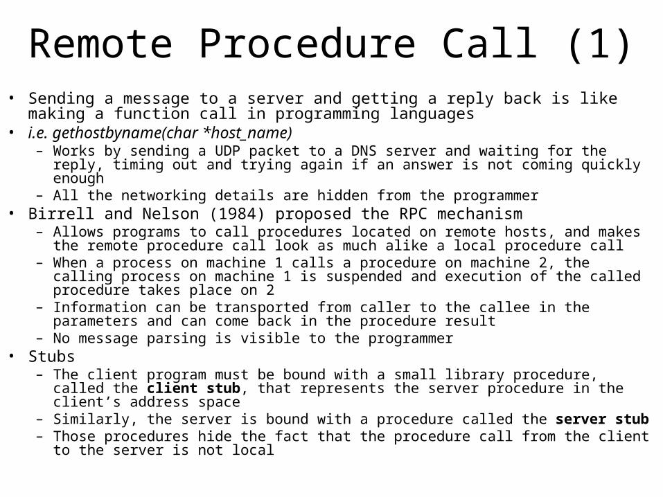
Remote Procedure Call (1)• Sending a message to a server and getting a reply back is like making a function call
in programming languages• i.e. gethostbyname(char *host_name)
– Works by sending a UDP packet to a DNS server and waiting for the reply, timing out and trying again if an answer is not coming quickly enough
– All the networking details are hidden from the programmer• Birrell and Nelson (1984) proposed the RPC mechanism
– Allows programs to call procedures located on remote hosts, and makes the remote procedure call look as much alike a local procedure call
– When a process on machine 1 calls a procedure on machine 2, the calling process on machine 1 is suspended and execution of the called procedure takes place on 2
– Information can be transported from caller to the callee in the parameters and can come back in the procedure result
– No message parsing is visible to the programmer• Stubs
– The client program must be bound with a small library procedure, called the client stub, that represents the server procedure in the client’s address space
– Similarly, the server is bound with a procedure called the server stub– Those procedures hide the fact that the procedure call from the client to the server is not
local
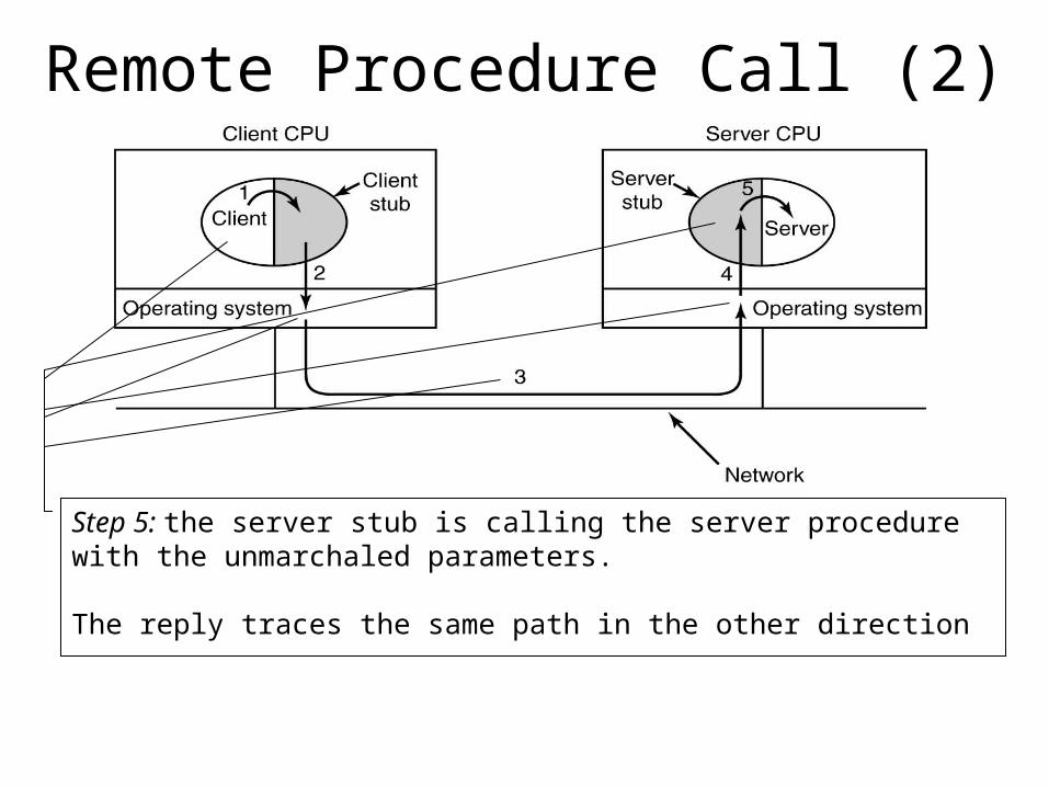
Remote Procedure Call (2)
Step 1: Client calling the client stub. This is a local procedure call, with the parameters pushed into the stack in the normal wayStep 2: the client stub is packing the parameters into a message and makes a system call to send the message; packing the parameters is called marshaling, and it is a very wide use technique.
Step 3: the kernel is sending the message from the client machine to the server machine, over a transport and network protocol.Step 4: the kernel on the receiving machine is passing the message from the transport stack to the server stub.Step 5: the server stub is calling the server procedure with the unmarchaled parameters.
The reply traces the same path in the other direction
Problems with RPC
• Use of pointer parameters– Using pointers is impossible, because the client and the
server are in different address spaces– Can be tricked by replacing the call by reference
mechanism with a copy-restore one
• Problems with custom defined type of data• Problems using global variables as means of
communication between the calling and called procedures– If the called procedure is moved on a remote machine,
because the variables are not longer shared
Transmission Control Protocol• Provides a reliable end to end byte stream over unreliable
internetwork (different parts may have different topologies, bandwidths, delays, packet sizes, etc…)
• Defined in RFC793, with some clarifications and bug fixes in RFC1122 and extensions in RFC1323
• Each machine supporting TCP has a TCP transport entity (user process or part of the kernel) that manages TCP streams and interfaces to the IP layer– Accepts user data streams from local processes, breaks them into pieces (not
larger than 64KB) and sends each piece as a separate IP datagram– At the receiving end, the IP datagrams that contains TCP packets, are delivered
to the TCP transport entity, which reconstructs the original byte stream– The IP layer gives no guarantee that the datagrams will be delivered properly,
so it is up to TCP to time out and retransmit them as the need arises. – Datagrams that arrive, may be in the wrong order; it is up to TCP to reassemble
them into messages in the proper sequence
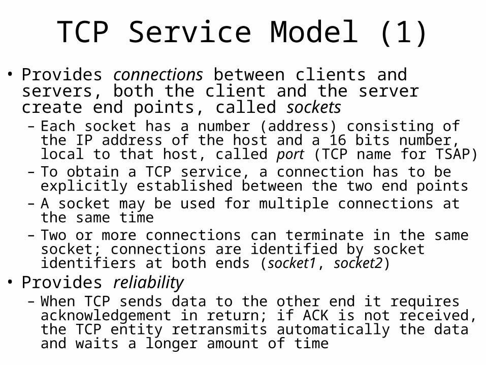
TCP Service Model (1)• Provides connections between clients and servers, both the
client and the server create end points, called sockets– Each socket has a number (address) consisting of the IP address of
the host and a 16 bits number, local to that host, called port (TCP name for TSAP)
– To obtain a TCP service, a connection has to be explicitly established between the two end points
– A socket may be used for multiple connections at the same time– Two or more connections can terminate in the same socket;
connections are identified by socket identifiers at both ends (socket1, socket2)
• Provides reliability– When TCP sends data to the other end it requires
acknowledgement in return; if ACK is not received, the TCP entity retransmits automatically the data and waits a longer amount of time
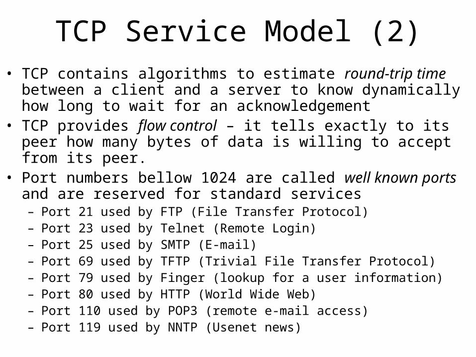
TCP Service Model (2)• TCP contains algorithms to estimate round-trip time between a client
and a server to know dynamically how long to wait for an acknowledgement
• TCP provides flow control – it tells exactly to its peer how many bytes of data is willing to accept from its peer.
• Port numbers bellow 1024 are called well known ports and are reserved for standard services– Port 21 used by FTP (File Transfer Protocol)– Port 23 used by Telnet (Remote Login)– Port 25 used by SMTP (E-mail)– Port 69 used by TFTP (Trivial File Transfer Protocol)– Port 79 used by Finger (lookup for a user information)– Port 80 used by HTTP (World Wide Web)– Port 110 used by POP3 (remote e-mail access)– Port 119 used by NNTP (Usenet news)
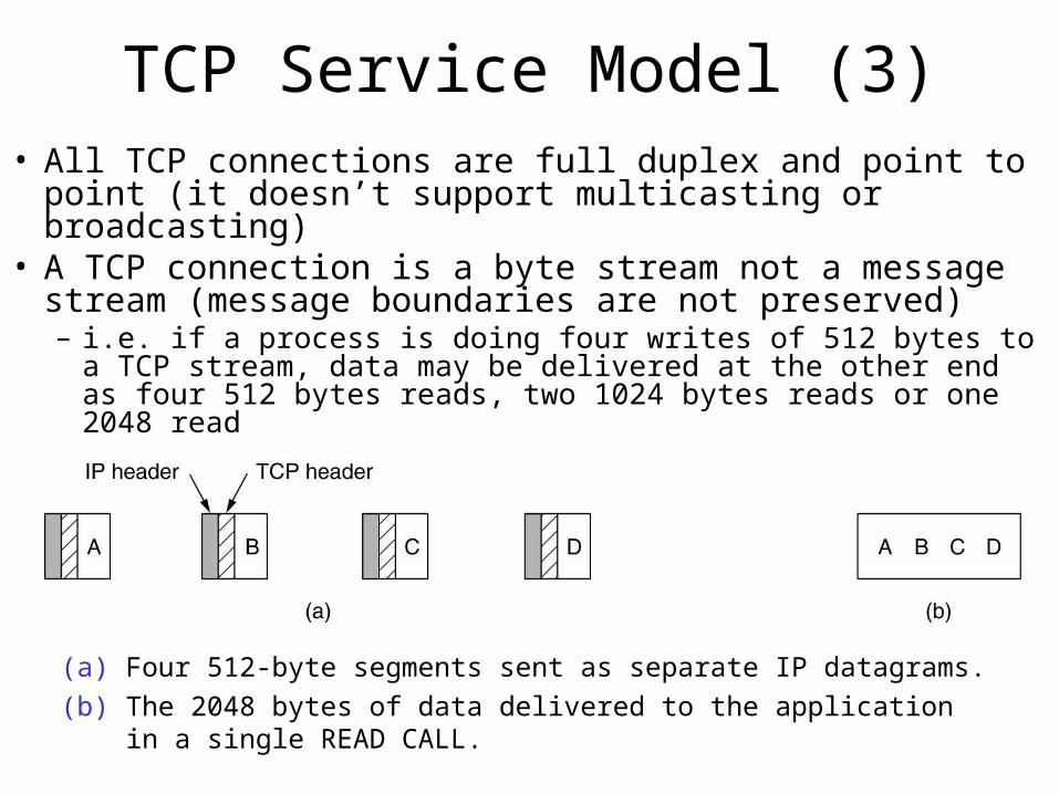
TCP Service Model (3)• All TCP connections are full duplex and point to point (it
doesn’t support multicasting or broadcasting)• A TCP connection is a byte stream not a message stream
(message boundaries are not preserved)– i.e. if a process is doing four writes of 512 bytes to a TCP stream,
data may be delivered at the other end as four 512 bytes reads, two 1024 bytes reads or one 2048 read
(a) Four 512-byte segments sent as separate IP datagrams.
(b) The 2048 bytes of data delivered to the application in a single READ CALL.
TCP Service Model (4) • When an application sends data to TCP, TCP entity may
send it immediately or buffer it (in order to collect a larger amount of data to send at once)– Sometimes the application really wants the data to be sent
immediately (i.e. after a command line has been finished); to force the data out, applications can use the PUSH flag (which tells TCP not to delay transmission)
• Urgent data – is a way of sending some urgent data from one application to another over TCP – i.e. when an interactive user hits DEL or CTRL-C key to break-off
the remote computation; the sending app puts some control info in the TCP stream along with the URGENT flag; this causes the TCP to stop accumulating data and send everything it has for that connection immediately; when the urgent data is received at the destination, the receiving application is interrupted (by sending a break signal in Unix), so it can read the data stream to find the urgent data
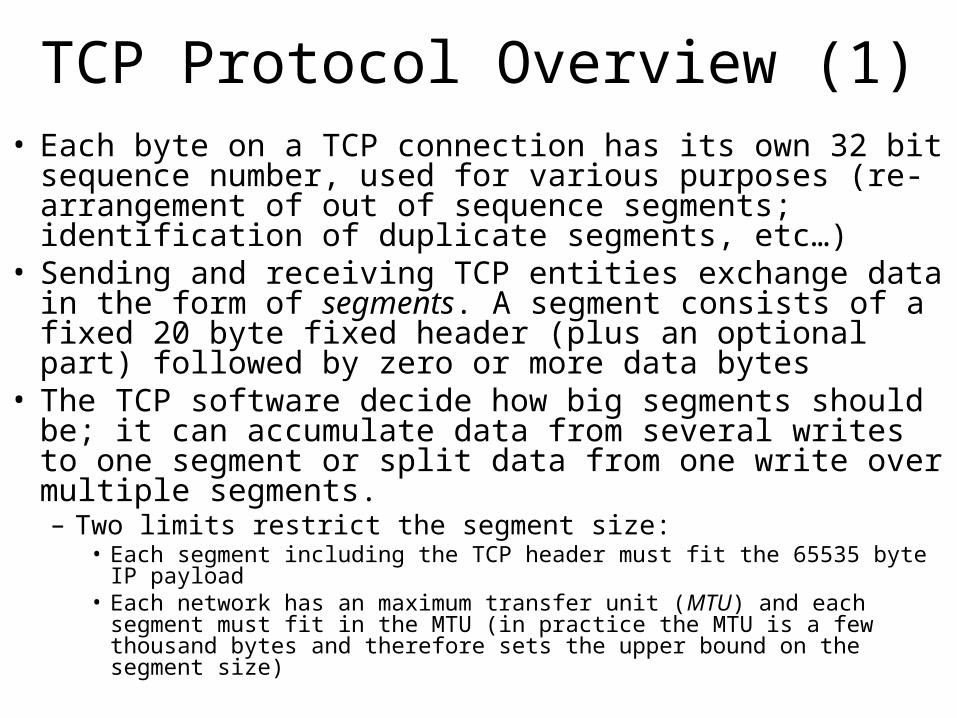
TCP Protocol Overview (1)• Each byte on a TCP connection has its own 32 bit sequence
number, used for various purposes (re-arrangement of out of sequence segments; identification of duplicate segments, etc…)
• Sending and receiving TCP entities exchange data in the form of segments. A segment consists of a fixed 20 byte fixed header (plus an optional part) followed by zero or more data bytes
• The TCP software decide how big segments should be; it can accumulate data from several writes to one segment or split data from one write over multiple segments.– Two limits restrict the segment size:
• Each segment including the TCP header must fit the 65535 byte IP payload• Each network has an maximum transfer unit (MTU) and each segment must
fit in the MTU (in practice the MTU is a few thousand bytes and therefore sets the upper bound on the segment size)
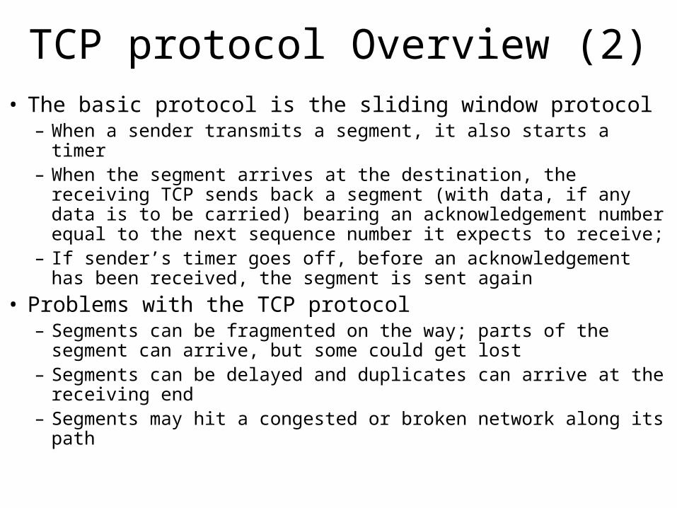
TCP protocol Overview (2)• The basic protocol is the sliding window protocol
– When a sender transmits a segment, it also starts a timer– When the segment arrives at the destination, the receiving TCP
sends back a segment (with data, if any data is to be carried) bearing an acknowledgement number equal to the next sequence number it expects to receive;
– If sender’s timer goes off, before an acknowledgement has been received, the segment is sent again
• Problems with the TCP protocol– Segments can be fragmented on the way; parts of the segment can
arrive, but some could get lost– Segments can be delayed and duplicates can arrive at the receiving
end– Segments may hit a congested or broken network along its path
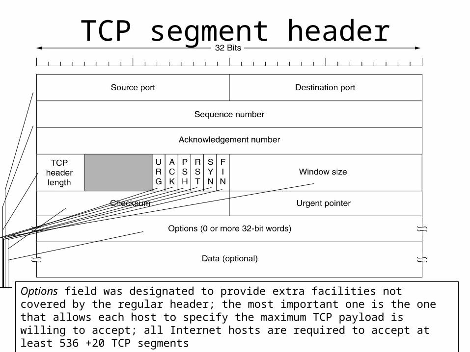
Source and destination ports identify the local endpoints for the connection; each host may decide for itself how to allocate the its own ports starting at 1024; a port number plus its host IP form a 48 bits unique TSAP
Sequence Number is associated with every byte that is sent. It is used for a number of different purposes: it is used to re-arrange the data at the receiving end, before passing it to the application; it is used to detect duplicate data and Acknowledgement number fields specifies the next byte expected
TCP header length tells how many 32 bit words are contained in the TCP header; this is required because the Options field is of variable length; technically it indicates the start of data within the segment, measured in 32 bits words.
URG flag is set to 1 if urgent pointer is in use; the urgent pointer is used to indicate a byte offset from the current sequence number at which urgent data is to be found; this facilitates interrupt messages without getting the TCP itself involved in carrying such message types
ACK flag is set to 1 to indicate that the acknowledgement number is valid; if set to 0, then the packet doesn’t contain an acknowledgement, so the appropriate field is ignored (the Acknowledgement number field is ignored)
PSH flag indicates pushed data, so the receiver is requested to deliver the received data to the application upon arrival, without buffering it to form a full buffer has been received
RST flag is used to restart a connection that has become confused due to a host crash or any other reasons; it is also used to reject an invalid segment or refuse an attempt to open a connection
SYN flag is used to establish connections; the connection requests have SYN = 1 and ACK = 0 to indicate that the piggyback acknowledgement field is not in use; the connection response does bear an acknowledgment so it has SYN = 1 and ACK = 1;
FIN flag is used to release connections; it specifies that the sender has no more data to transmit; Both SYN and FYN segments have sequence number and thus guaranteed to be processed in correct order
Flow control in TCP is done using variable size sliding window; the Window size field tells how many bytes may be sent starting at the byte acknowledged; a window size field with value 0 is legal and means that bytes up to (Acknowledgement number -1) have been received, and no more accepted
Checksum is provided for extreme reliability. It checksums the header, the data and the conceptual pseudo-header shown on the next slide; when performing the computation, the data field is padded with an additional zero byte if its length is an odd number; the checksum is simply the sum in 1’s complement
Options field was designated to provide extra facilities not covered by the regular header; the most important one is the one that allows each host to specify the maximum TCP payload is willing to accept; all Internet hosts are required to accept at least 536 +20 TCP segments
TCP segment header
TCP pseudoheader
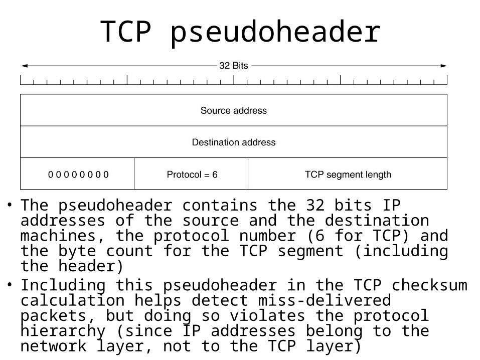
• The pseudoheader contains the 32 bits IP addresses of the source and the destination machines, the protocol number (6 for TCP) and the byte count for the TCP segment (including the header)
• Including this pseudoheader in the TCP checksum calculation helps detect miss-delivered packets, but doing so violates the protocol hierarchy (since IP addresses belong to the network layer, not to the TCP layer)
TCP extra options• For lines with high bandwidth and high delay, the 64KB widow size
is often a problem– i.e. on a T3 line (44.736 Mb/s) it takes only about 12ms to output a full 64KB
window. If the round trip propagation delay is 50 ms (typical for a transcontinental fiber), then the sender will be idle ¾ of the time, waiting for acknowledgements
– In RFC 1323 a window scale option was proposed, allowing the sender and receiver to negotiate a window scale factor. This number allows both sides to shift the window size up to 14 bits to the left, thus allowing for window size up to 230 bytes; most TCP implementations support this option
• The use of “selective repeat” instead of “go and back n” protocol described in RFC 1106– If the receiver gets a bad segment and then a large number of good ones, the
normal TCP protocol eventually time out and retransmit all the unacknowledged segments, including the ones that were received correctly
– RFC 1106 introduces NACs to allow the receiver to ask for a specific segment (or segments). After it gets those, it can acknowledge all the buffered data, thus reducing the amount of data retransmitted.
TCP connection establishment
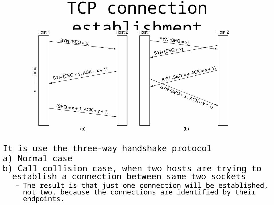
It is use the three-way handshake protocola) Normal caseb) Call collision case, when two hosts are trying to establish a
connection between same two sockets– The result is that just one connection will be established, not two, because the
connections are identified by their endpoints.

TCP connection establishment …client server
socket, bind, listen
accept (bocks)
socket
connect (blocks)SYN X
SYN Y, ACK X+1(active
connection)
connect returns SEQ = X+1, ACK=Y+1 accept returns
read (blocks)
(pasive connection)1
2
3
4
[1] the server must be prepared to accept an incoming connection; this is normally done by calling socket, bind and listen and it is called passive open
[2] the client, after the creation of a new socket, issues an active open by calling connect. This causes the client TCP to send a SYN segment (which stands for synchronize) to tell the server the client’s initial sequence number for the data that the client will send on the connection; normally there is no data sent with SYN: it just contains an IP header, a TCP header and possible TCP options
[3] the server must acknowledge the client’s SYN and the server must also send its own SYN containing the initial sequence number for the data that the server will send on the connection. The server sends SYN and the ACK of the client’s SYN in a single segment
[4]the client must acknowledge the server’s SYN
Note that SYN consumes one byte of sequence space so it can be acknowledged unambiguously
The initial sequence number on a connection is not 0 (to avoid confusion when a host crashes). A clock based scheme is used, with a clock tick every 4 us. For additional safety, when a host crashes, it may not reboot for the maximum packet life time (120s) to make sure that no packets from previous connections are still roaming around the Internet, somewhere.
TCP connection termination• The connection is full duplex, each simple connection is released
independently• To release a connection, either party can send a TCP segment with
FIN bit set, which means that there is no more data to transmit• When FIN is acknowledged, that direction is shut down for new data;
however, data may continue to flow indefinitely in the other direction• When both directions have been shutdown, the connection is released• Normally, four TCP segments are used to shutdown the connection
(one FIN and one ACK for each direction)• To avoid complications when segments are lost, timers are used; if the
ACK for a FIN packet is not arriving in two packet lifetimes, the sender of the FIN releases the connection; the other side will eventually realize that nobody seem to listen to it anymore and times out as well
TCP connection terminationclient server
read returns 0
closeFIN M
ACK M+1
(active close)
ACK=N+1
(pasive close)
1
2
3
4
closeFIN N
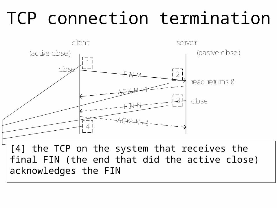
[1] one application calls close first, and we say that this end performs the active close. This end’s TCP sends a FIN segment, which means it is finished sending data
[2] the other end receives the FIN and performs a passive close. The received SYN is acknowledged by the TCP; the receipt of the FIN is also passed onto the application as an end-of-file; upon the receipt of FIN, the application will not receive anymore any data on the socket
[3] sometime latter, the application that received the end-of-file will close the socket; this will cause its TCP to send a FIN packet[4] the TCP on the system that receives the final FIN (the end that did the active close) acknowledges the FIN
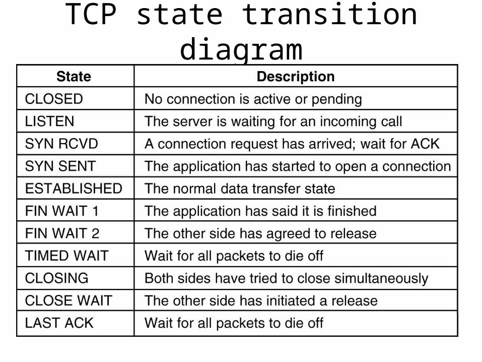
TCP state transition diagram
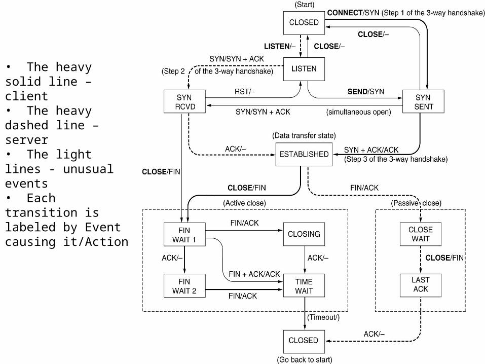
• The heavy solid line – client• The heavy dashed line – server• The light lines - unusual events• Each transition is labeled by Event causing it/Action
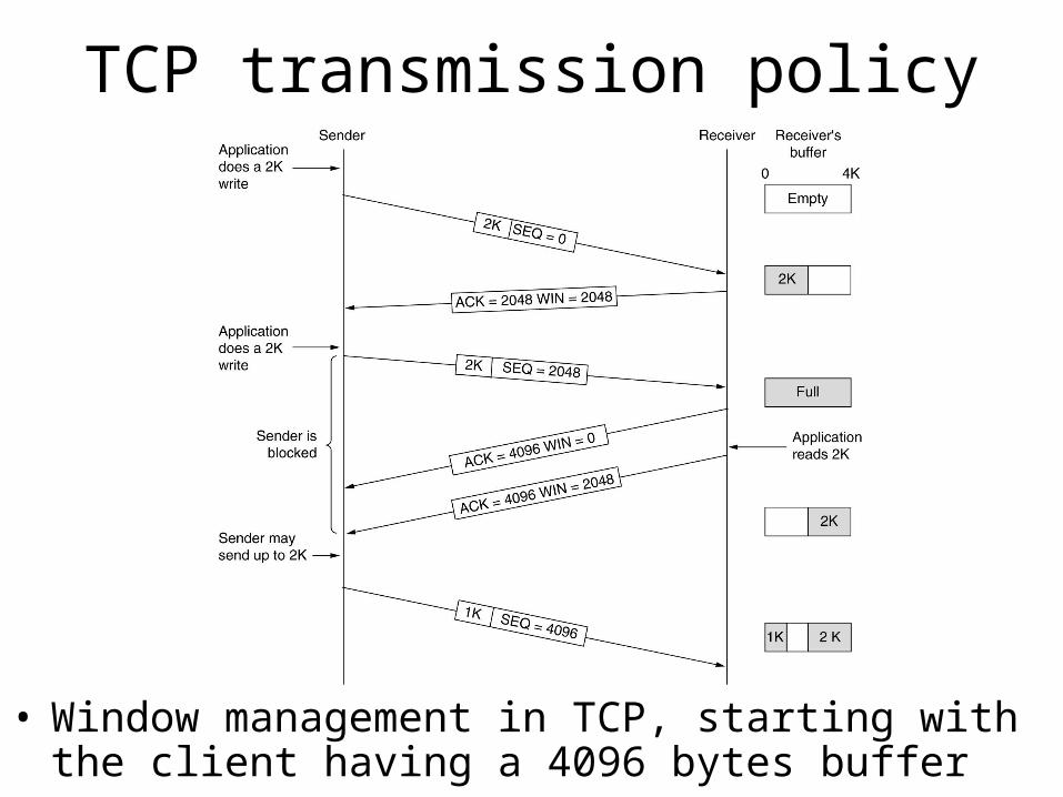
TCP transmission policy
• Window management in TCP, starting with the client having a 4096 bytes buffer
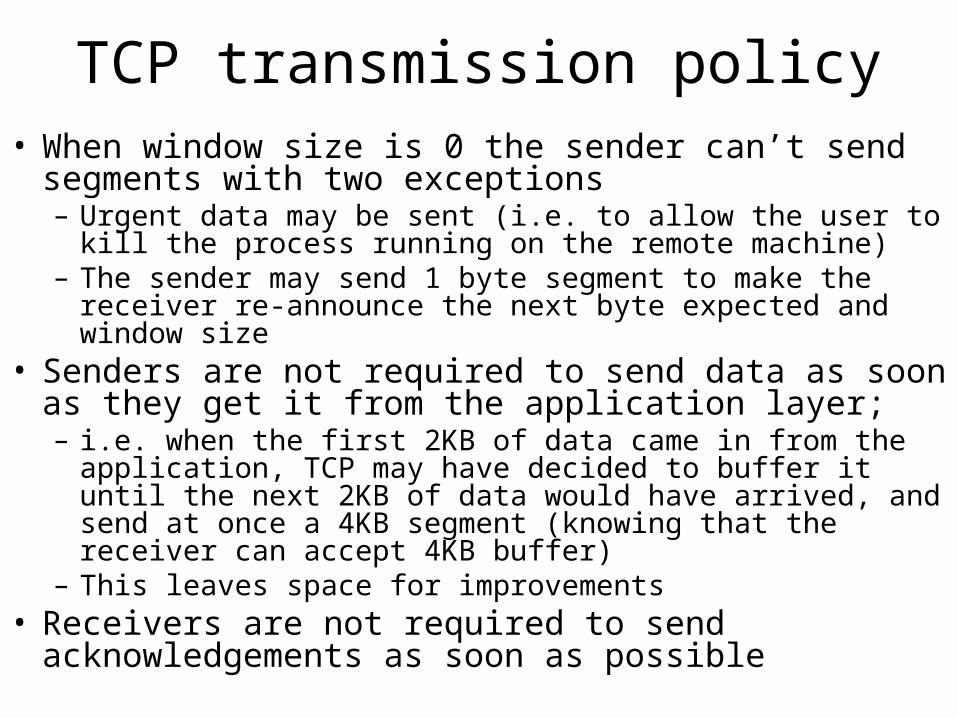
TCP transmission policy• When window size is 0 the sender can’t send segments with
two exceptions– Urgent data may be sent (i.e. to allow the user to kill the process
running on the remote machine)– The sender may send 1 byte segment to make the receiver re-
announce the next byte expected and window size• Senders are not required to send data as soon as they get it
from the application layer;– i.e. when the first 2KB of data came in from the application, TCP
may have decided to buffer it until the next 2KB of data would have arrived, and send at once a 4KB segment (knowing that the receiver can accept 4KB buffer)
– This leaves space for improvements• Receivers are not required to send acknowledgements as
soon as possible
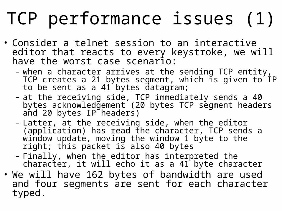
TCP performance issues (1)• Consider a telnet session to an interactive editor that reacts
to every keystroke, we will have the worst case scenario:– when a character arrives at the sending TCP entity, TCP creates a
21 bytes segment, which is given to IP to be sent as a 41 bytes datagram;
– at the receiving side, TCP immediately sends a 40 bytes acknowledgement (20 bytes TCP segment headers and 20 bytes IP headers)
– Latter, at the receiving side, when the editor (application) has read the character, TCP sends a window update, moving the window 1 byte to the right; this packet is also 40 bytes
– Finally, when the editor has interpreted the character, it will echo it as a 41 byte character
• We will have 162 bytes of bandwidth are used and four segments are sent for each character typed.
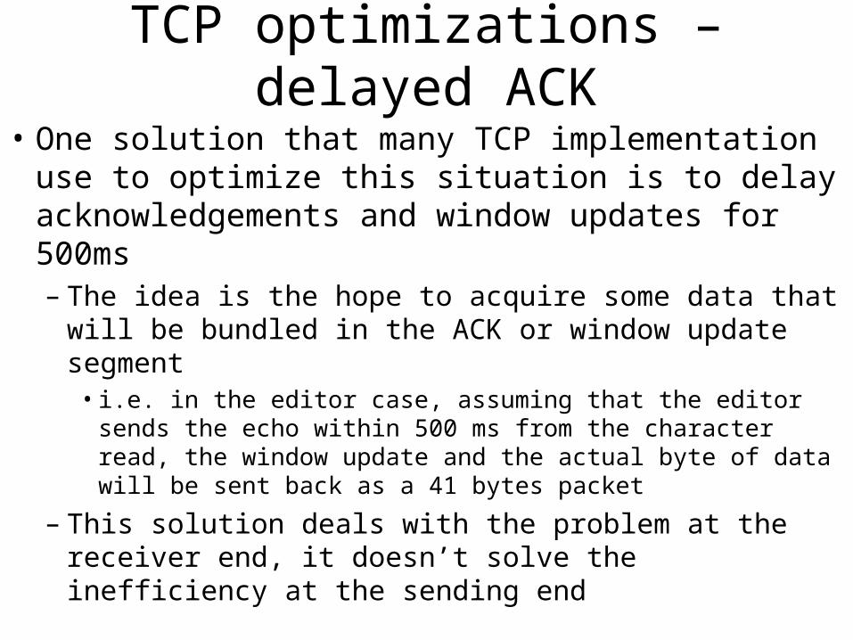
TCP optimizations – delayed ACK
• One solution that many TCP implementation use to optimize this situation is to delay acknowledgements and window updates for 500ms– The idea is the hope to acquire some data that will be
bundled in the ACK or window update segment • i.e. in the editor case, assuming that the editor sends the echo
within 500 ms from the character read, the window update and the actual byte of data will be sent back as a 41 bytes packet
– This solution deals with the problem at the receiver end, it doesn’t solve the inefficiency at the sending end
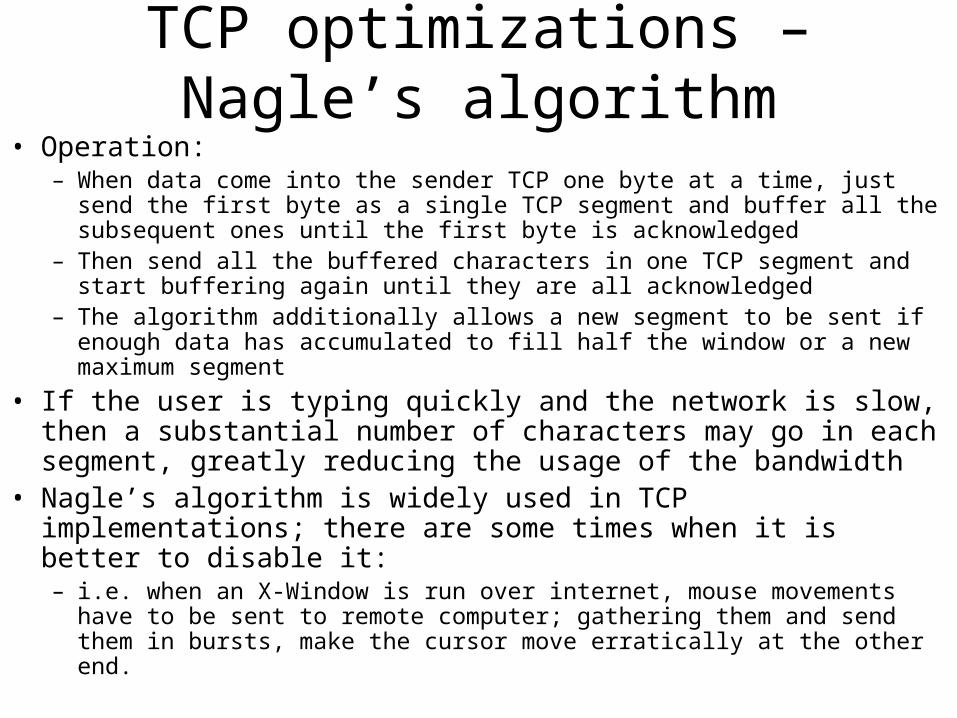
TCP optimizations – Nagle’s algorithm• Operation:
– When data come into the sender TCP one byte at a time, just send the first byte as a single TCP segment and buffer all the subsequent ones until the first byte is acknowledged
– Then send all the buffered characters in one TCP segment and start buffering again until they are all acknowledged
– The algorithm additionally allows a new segment to be sent if enough data has accumulated to fill half the window or a new maximum segment
• If the user is typing quickly and the network is slow, then a substantial number of characters may go in each segment, greatly reducing the usage of the bandwidth
• Nagle’s algorithm is widely used in TCP implementations; there are some times when it is better to disable it:– i.e. when an X-Window is run over internet, mouse movements have to be sent
to remote computer; gathering them and send them in bursts, make the cursor move erratically at the other end.
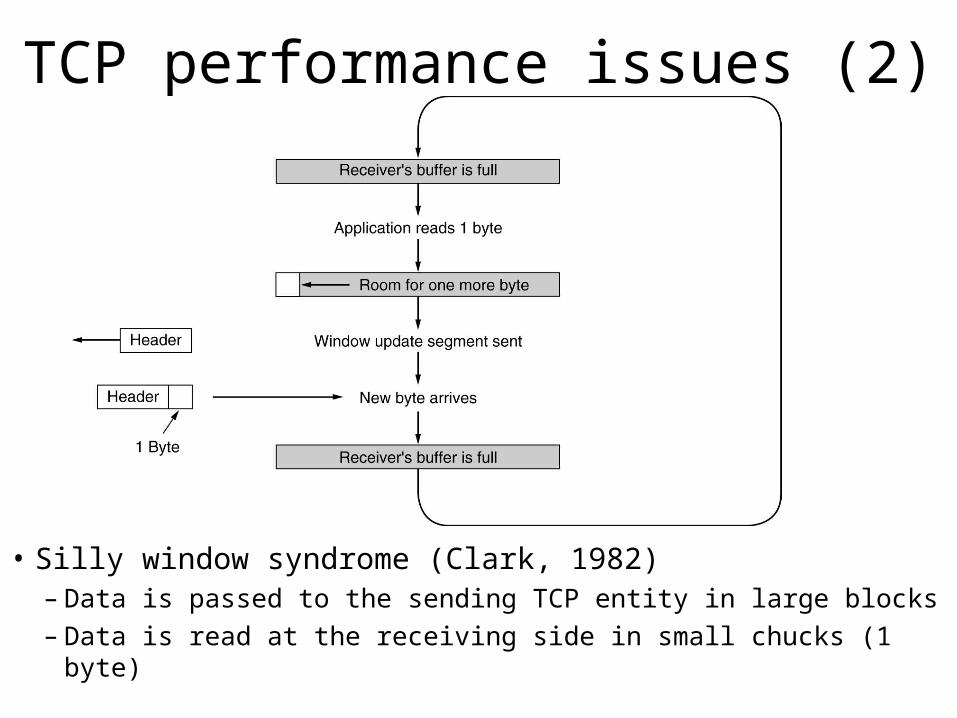
TCP performance issues (2)
• Silly window syndrome (Clark, 1982)– Data is passed to the sending TCP entity in large blocks– Data is read at the receiving side in small chucks (1 byte)
TCP optimizations – Clark’s solution
• Clark’s solution:– Prevent the receiver from sending a window update for 1 byte
– Instead have the receiver to advertise a decent amount of space available; specifically, the receiver should not send a window update unless it has space to handle the maximum segment size (that has been advertised when the connection was established) or its receiving buffer its half empty, which ever is smaller
– Furthermore, the sender can help by not sending small segments; instead it should wait until it has accumulated enough space in the window to send a full segment or at least one containing half of the receiver’s buffer size (which can be estimated from the pattern of window updates it has received in the past)
Nagle’s algorithm vs. Clark’s solution• Clark’s solution to the silly window syndrome and Nagle’s
algorithm are complementary– Nagle was trying to solve the problem caused by the sending
application deliver data to TCP one byte at a time– Clark was trying to solve the problem caused by the receiving
application reading data from TCP one byte at a time– Both solutions are valid and can work together. The goal is for the
sender not to send small segments and the receiver not to ask for them
• The receiving TCP can also improve performance by blocking a READ request from the application until it has a large chunk of data to provide:– However, this can increase the response time.– But, for non-interactive applications (e.g. file transfer) efficiency
may outweigh the response time to individual requests.
TCP congestion control
• TCP deals with congestion by dynamically manipulating the window size
• First step in managing the congestion is to detect it– A timeout caused by a lost packet can be caused by
• Noise on the transmission line (not really an issue for modern infrastructure)
• Packet discard at a congested router
– Most transmission timeouts are due congestion
• All the Internet TCP algorithms assume that timeouts are due to congestion and monitor timeouts to detect congestion
TCP congestion control
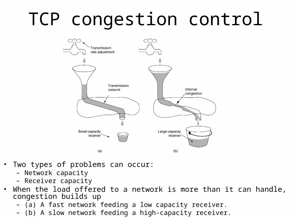
• Two types of problems can occur:– Network capacity– Receiver capacity
• When the load offered to a network is more than it can handle, congestion builds up– (a) A fast network feeding a low capacity receiver.– (b) A slow network feeding a high-capacity receiver.
TCP congestion control
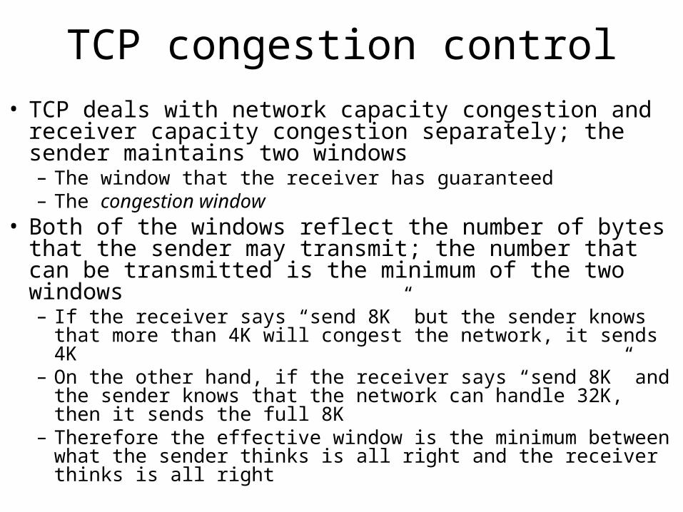
• TCP deals with network capacity congestion and receiver capacity congestion separately; the sender maintains two windows– The window that the receiver has guaranteed– The congestion window
• Both of the windows reflect the number of bytes that the sender may transmit; the number that can be transmitted is the minimum of the two windows– If the receiver says “send 8K” but the sender knows that more than
4K will congest the network, it sends 4K– On the other hand, if the receiver says “send 8K” and the sender
knows that the network can handle 32K, then it sends the full 8K– Therefore the effective window is the minimum between what the
sender thinks is all right and the receiver thinks is all right
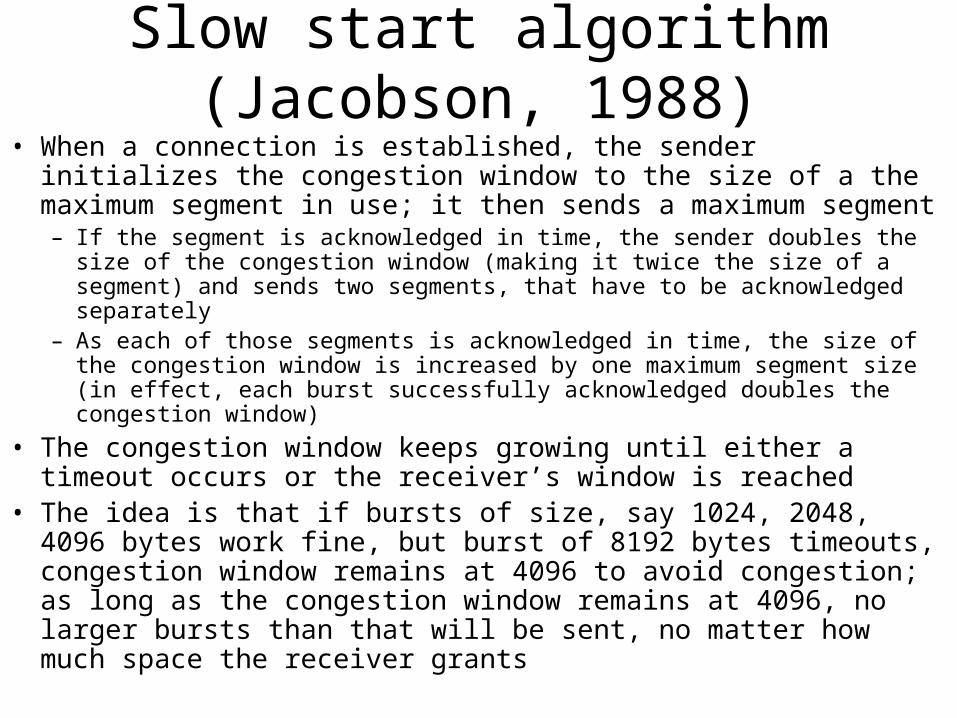
Slow start algorithm (Jacobson, 1988)• When a connection is established, the sender initializes the congestion
window to the size of a the maximum segment in use; it then sends a maximum segment– If the segment is acknowledged in time, the sender doubles the size of the
congestion window (making it twice the size of a segment) and sends two segments, that have to be acknowledged separately
– As each of those segments is acknowledged in time, the size of the congestion window is increased by one maximum segment size (in effect, each burst successfully acknowledged doubles the congestion window)
• The congestion window keeps growing until either a timeout occurs or the receiver’s window is reached
• The idea is that if bursts of size, say 1024, 2048, 4096 bytes work fine, but burst of 8192 bytes timeouts, congestion window remains at 4096 to avoid congestion; as long as the congestion window remains at 4096, no larger bursts than that will be sent, no matter how much space the receiver grants
Slow start algorithm (Jacobson, 1988)
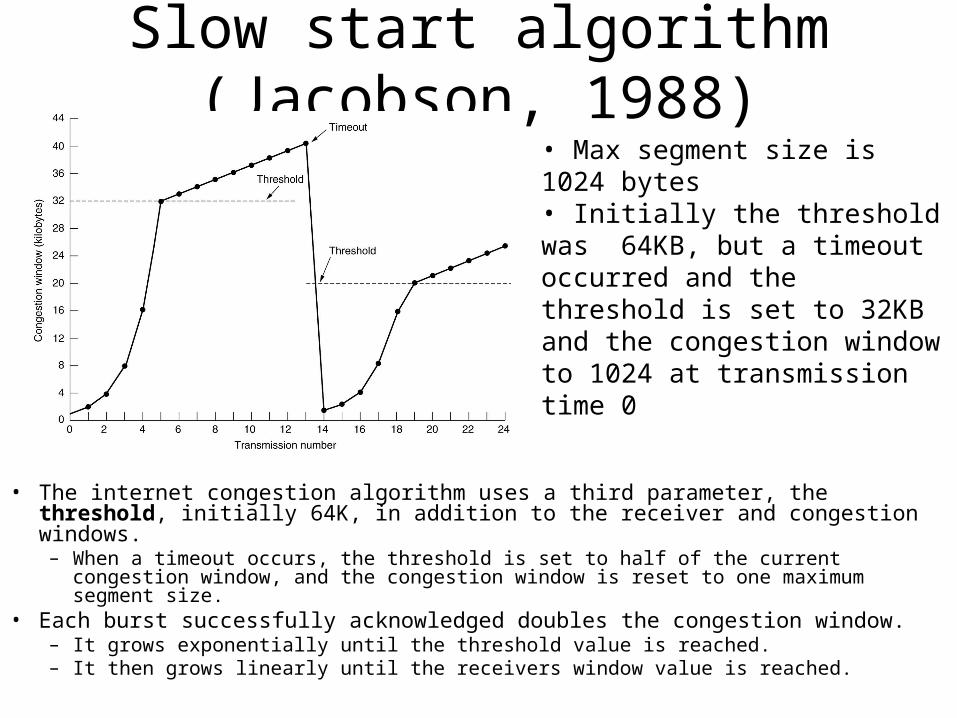
• The internet congestion algorithm uses a third parameter, the threshold, initially 64K, in addition to the receiver and congestion windows.– When a timeout occurs, the threshold is set to half of the current congestion window, and
the congestion window is reset to one maximum segment size.• Each burst successfully acknowledged doubles the congestion window.
– It grows exponentially until the threshold value is reached.– It then grows linearly until the receivers window value is reached.
• Max segment size is 1024 bytes• Initially the threshold was 64KB, but a timeout occurred and the threshold is set to 32KB and the congestion window to 1024 at transmission time 0
TCP timer management
• TCP uses multiple timers to do its work– The most important is the retransmission timer
• When a segment is sent, a retransmission timer is started
• If the segment is acknowledged before this timer expires, the timer is stopped
• If the timer goes off before the segment is acknowledged, then the segment gets retransmitted (and the timer restarted)
• The big question is how long this timer interval should be?
– Keepalive timer is designed to check for connection integrity
• When goes off (because a long time of inactivity), causing one side to check if the other side is still there
TCP timer management
• TCP uses multiple timers to do its work– Persistence timer is designed to prevent deadlock
• Receiver sends a packet with window size 0• Latter, it sends another packet with larger window size, letting
the sender know that it can send data, but this segment gets lost• Both the receiver and transmitter are waiting for the other• Solution: persistence timer on the sender end, that goes off and
produces a probe packet to go to the receiver and make it to advertise again its window
– TIMED WAIT state timer used when a connection is closed; it runs for twice the maximum packet lifetime to make sure that when a connection is closed, all packets belonging to this connection have died off.
Wireless TCP
• The principal problem is the congestion control algorithm, because most of the TCP implementations assume that timeouts are caused by congestion and not by lost packets
• Wireless networks are highly unreliable – The best approach with lost packets is to send them ASAP,
slowing down (Jacobson slow start) only makes things worst
• When a packet is lost– On wired networks, the sender should slow down
– On wireless networks, the sender should try harder
• If the type of network is not known, it is difficult to make the correct decision
Wireless TCP
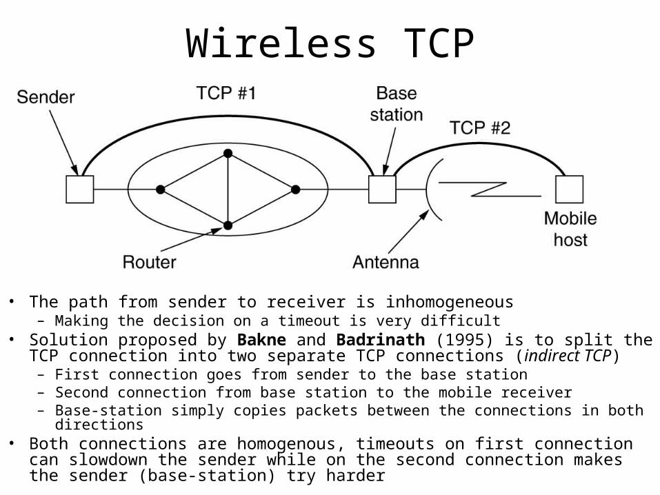
• The path from sender to receiver is inhomogeneous– Making the decision on a timeout is very difficult
• Solution proposed by Bakne and Badrinath (1995) is to split the TCP connection into two separate TCP connections (indirect TCP)– First connection goes from sender to the base station– Second connection from base station to the mobile receiver– Base-station simply copies packets between the connections in both directions
• Both connections are homogenous, timeouts on first connection can slowdown the sender while on the second connection makes the sender (base-station) try harder
Wireless TCP - Balakrishnan et al (1995)• Doesn’t break the semantics of the TCP, works by making small
modifications of the code at the base station end– Addition of an agent that would cache all the TCP segments going out to the
TCP mobile host and ACK coming back from it; – When the agent sees a TCP segment going out but no ACK coming back, it will
issue a retransmission without letting the sender know what is going on– It also generates retransmission when it sees duplicate ACK coming from the
mobile host (it means the mobile host missed something)– Duplicate ACK are discarded by the agent (to avoid the source interpret it as
congestion)• One problem is that if the wireless net is very lossy, the sender may
timeout and invoke the congestion control algorithm; with indirect TCP the congestion algorithm wouldn’t be started unless there is really congestion in the wired part
• There is a fix for to the problem of lost segments originating at the mobile host– When the base-station notices a gap in the inbound sequence numbers, it
generates a request for a selective repeat of the missing bytes using a TCP option
References
• Andrew S. Tanenbaum – Computer Networks, ISBN: 0-13066102-3
• Behrouz A. Forouzan – Data Communications and Networking, ISBN: 0-07-118160-1
Additional Slides
Quality of service
RTTP, RTCP and Transactional TCP
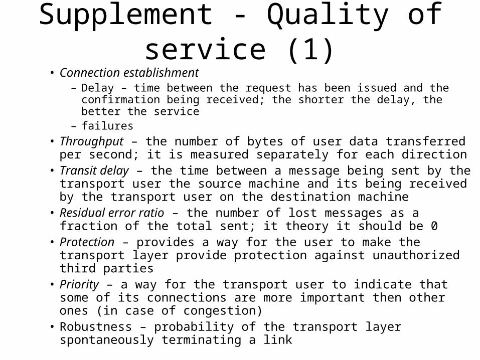
Supplement - Quality of service (1)• Connection establishment
– Delay – time between the request has been issued and the confirmation being received; the shorter the delay, the better the service
– failures
• Throughput – the number of bytes of user data transferred per second; it is measured separately for each direction
• Transit delay – the time between a message being sent by the transport user the source machine and its being received by the transport user on the destination machine
• Residual error ratio – the number of lost messages as a fraction of the total sent; it theory it should be 0
• Protection – provides a way for the user to make the transport layer provide protection against unauthorized third parties
• Priority – a way for the transport user to indicate that some of its connections are more important then other ones (in case of congestion)
• Robustness – probability of the transport layer spontaneously terminating a link
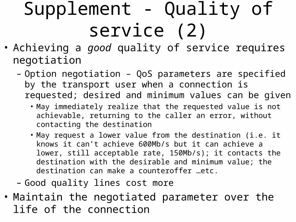
Supplement - Quality of service (2)
• Achieving a good quality of service requires negotiation– Option negotiation – QoS parameters are specified by the transport
user when a connection is requested; desired and minimum values can be given
• May immediately realize that the requested value is not achievable, returning to the caller an error, without contacting the destination
• May request a lower value from the destination (i.e. it knows it can’t achieve 600Mb/s but it can achieve a lower, still acceptable rate, 150Mb/s); it contacts the destination with the desirable and minimum value; the destination can make a counteroffer …etc.
– Good quality lines cost more
• Maintain the negotiated parameter over the life of the connection
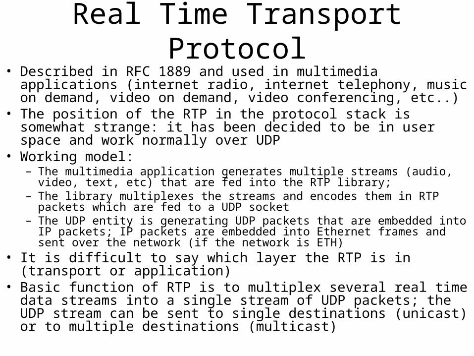
Real Time Transport Protocol• Described in RFC 1889 and used in multimedia applications (internet
radio, internet telephony, music on demand, video on demand, video conferencing, etc..)
• The position of the RTP in the protocol stack is somewhat strange: it has been decided to be in user space and work normally over UDP
• Working model:– The multimedia application generates multiple streams (audio, video, text, etc)
that are fed into the RTP library; – The library multiplexes the streams and encodes them in RTP packets which are
fed to a UDP socket– The UDP entity is generating UDP packets that are embedded into IP packets;
IP packets are embedded into Ethernet frames and sent over the network (if the network is ETH)
• It is difficult to say which layer the RTP is in (transport or application)
• Basic function of RTP is to multiplex several real time data streams into a single stream of UDP packets; the UDP stream can be sent to single destinations (unicast) or to multiple destinations (multicast)
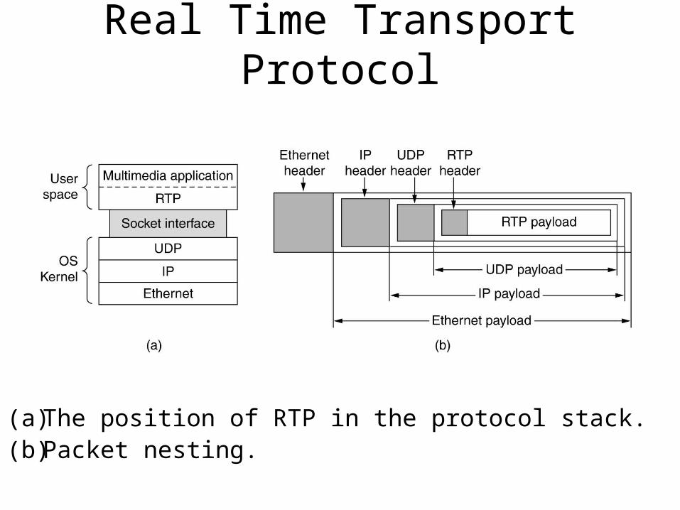
Real Time Transport Protocol
(a) The position of RTP in the protocol stack. (b) Packet nesting.
Real Time Transport Protocol
• Each packet has a number, one higher than its predecessor– Used by the destination to determine missing packets– If packet is missing, best action is to try and interpolate it
• No flow control, no retransmission, no error control
• RTP payload may contain multiple samples coded any way the application wants
• Allows for time-stamping (time relative to the start of the stream, so only differences are significant)– This is used to play synchronously certain streams
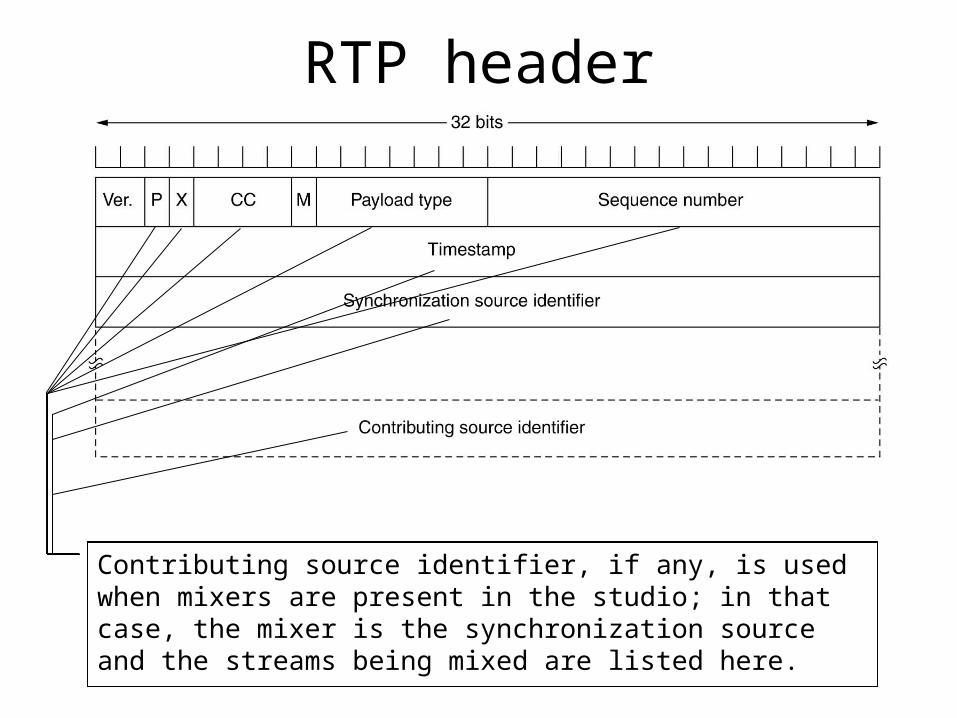
RTP header
The P bit indicates that the packet has been padded to a multiple of 4 bytes; the last padding byte tells how many bytes were added The X bit tells that an extension header is present; the format and meaning of the extension header are not defined; the only thing that is defined is the first word of the extension that gives the length; this is an escape mechanism for unforeseen requirements
The CC field tells how many contributing sources are presentThe M bit is an application specific marker bit; it can be used to mark the start of a video frame
The Payload type field tells which encoding algorithm has been used (MP3, PCM, etc); since every packet carries this field, the encoding can change during transmission
Sequence number is just a counter that increments on each RTP packet sent; it is used to detect lost packetsThe timestamp is produced by the stream’s source to note when the first sample in the packet was made; this field can help reduce jitter by decoupling the playback from the packet arrival time
Synchronization source identifier tells which stream the packet belongs to; it is the method used to multiplex and demultiplex multiple data streams over one single stream of UDP packets.
Contributing source identifier, if any, is used when mixers are present in the studio; in that case, the mixer is the synchronization source and the streams being mixed are listed here.

Real Time Transport Control Protocol
• It handles feedback, synchronization for the RTP but is not actually transporting any data
• Feedback on delay, jitter, bandwidth, congestion and any other networking parameters
• Handles inter-stream synchronization whenever different streams use different clocks with different granularities
• Provides a way of naming different sources (i.e. in ASCII text); this information can be displayed at the receiver end to display who is talking at the moment
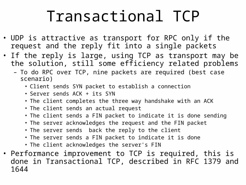
Transactional TCP• UDP is attractive as transport for RPC only if the request and the
reply fit into a single packets• If the reply is large, using TCP as transport may be the solution, still
some efficiency related problems– To do RPC over TCP, nine packets are required (best case scenario)
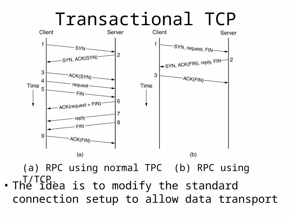
• Client sends SYN packet to establish a connection• Server sends ACK + its SYN• The client completes the three way handshake with an ACK• The client sends an actual request• The client sends a FIN packet to indicate it is done sending• The server acknowledges the request and the FIN packet• The server sends back the reply to the client• The server sends a FIN packet to indicate it is done• The client acknowledges the server's FIN
• Performance improvement to TCP is required, this is done in Transactional TCP, described in RFC 1379 and 1644
Transactional TCP
(a) RPC using normal TPC (b) RPC using T/TCP.
• The idea is to modify the standard connection setup to allow data transport