Embed Size (px)
Citation preview

Technical Specification Transport and Main Roads Specification MRTS202 Variable Message Signs November 2021

Transport and Main Roads Specifications, November 2021
Copyright © The State of Queensland (Department of Transport and Main Roads) 2021. Licence
This work is licensed by the State of Queensland (Department of Transport and Main Roads) under a Creative Commons Attribution (CC BY) 4.0 International licence. CC BY licence summary statement In essence, you are free to copy, communicate and adapt this work, as long as you attribute the work to the State of Queensland (Department of Transport and Main Roads). To view a copy of this licence, visit: https://creativecommons.org/licenses/by/4.0/ Translating and interpreting assistance
The Queensland Government is committed to providing accessible services to Queenslanders from all cultural and linguistic backgrounds. If you have difficulty understanding this publication and need a translator, please call the Translating and Interpreting Service (TIS National) on 13 14 50 and ask them to telephone the Queensland Department of Transport and Main Roads on 13 74 68.
Disclaimer While every care has been taken in preparing this publication, the State of Queensland accepts no responsibility for decisions or actions taken as a result of any data, information, statement or advice, expressed or implied, contained within. To the best of our knowledge, the content was correct at the time of publishing. Feedback Please send your feedback regarding this document to: [email protected]

Transport and Main Roads Specifications, November 2021 i
Contents
1 Introduction ....................................................................................................................................1
2 Definition of terms .........................................................................................................................1
3 Reference documents ...................................................................................................................2
4 Quality system requirements .......................................................................................................3
4.1 General ........................................................................................................................................... 3
4.2 Sample variable message sign ....................................................................................................... 4
4.3 Warranty ......................................................................................................................................... 4
5 Functional requirements ...............................................................................................................4
5.1 General ........................................................................................................................................... 4
5.2 Control methods.............................................................................................................................. 5
5.3 VMS controller ................................................................................................................................ 5
5.4 Communications timeout ................................................................................................................ 5
5.5 Configuration management ............................................................................................................ 5
5.6 Sign fault management ................................................................................................................... 5
5.7 Local event logging ......................................................................................................................... 6
5.8 Watchdog ........................................................................................................................................ 6
5.9 Time synchronisation ...................................................................................................................... 6
6 VMS configuration options ...........................................................................................................6
7 Mechanical and physical requirements .......................................................................................7
7.1 Design life ....................................................................................................................................... 7
7.2 Display enclosure ........................................................................................................................... 7
7.3 Mounting structure .......................................................................................................................... 7
7.4 Field cabinets .................................................................................................................................. 7
8 Variable message display requirements .....................................................................................8
8.1 General ........................................................................................................................................... 8
8.2 Variable message display technology ............................................................................................ 8
8.3 Failures ........................................................................................................................................... 8
8.4 LED output ...................................................................................................................................... 8
8.5 Display Unit Requirements ............................................................................................................. 8
8.6 Display fonts ................................................................................................................................... 9
8.7 Display changes.............................................................................................................................. 9
8.8 Display colour ................................................................................................................................. 9
8.9 Fall-back displays ......................................................................................................................... 10
8.10 Conspicuity devices ...................................................................................................................... 10
8.11 Optical performance ..................................................................................................................... 10 8.11.1 Luminance ................................................................................................................... 10 8.11.2 LED dimming ............................................................................................................... 10 8.11.3 Luminance intensity half angle .................................................................................... 10

Transport and Main Roads Specifications, November 2021 ii
8.11.4 Luminance intensity uniformity .................................................................................... 10 8.11.5 Sun phantom ............................................................................................................... 10
9 Control system ............................................................................................................................ 10
9.1 General ......................................................................................................................................... 10
9.2 Local facility switch ....................................................................................................................... 11
9.3 Maintenance communications port ............................................................................................... 11
9.4 Control communications port ........................................................................................................ 11
9.5 Control / diagnostics software ....................................................................................................... 11 9.5.1 Security and compatibility ............................................................................................ 12 9.5.2 Configuration settings and firmware ............................................................................ 12
9.6 Hardwired inputs ........................................................................................................................... 12
9.7 Message hierarchy ....................................................................................................................... 12
9.8 LED intensity control ..................................................................................................................... 13 9.8.1 Time-of-Day intensity settings ..................................................................................... 13
9.9 Temperature control ..................................................................................................................... 13
9.10 Communication protocol ............................................................................................................... 13
9.11 Bus arbitration ............................................................................................................................... 14 9.11.1 Display controls ........................................................................................................... 14
10 Mechanical, physical and display enclosure requirements ................................................... 14
10.1 General ......................................................................................................................................... 14
10.2 Mounting ....................................................................................................................................... 14
10.3 Exterior finish and surfaces .......................................................................................................... 14
10.4 Weather resistance ....................................................................................................................... 14
10.5 Equipment racks ........................................................................................................................... 14
10.6 Front cover .................................................................................................................................... 15 10.6.1 Front cover material..................................................................................................... 15 10.6.2 Viewing angles ............................................................................................................ 15 10.6.3 Retention method ........................................................................................................ 15
10.7 Demister ........................................................................................................................................ 15
11 Environmental ............................................................................................................................. 15
12 Electrical ...................................................................................................................................... 15
12.1 Power source ................................................................................................................................ 15
12.2 Power consumption ...................................................................................................................... 16
13 Installation requirements ........................................................................................................... 16
14 Telecommunications requirements .......................................................................................... 16
15 Testing and commissioning ...................................................................................................... 16
15.1 General ......................................................................................................................................... 16
15.2 Factory acceptance tests (FAT) .................................................................................................... 16
15.3 Installation acceptance tests (IAT)................................................................................................ 17
15.4 Commissioning tests (CT) ............................................................................................................ 17
16 Documentation ............................................................................................................................ 17

Transport and Main Roads Specifications, November 2021 iii
17 Training ........................................................................................................................................ 17
18 Maintenance ................................................................................................................................ 17
19 Handover ..................................................................................................................................... 17
20 Product Approval ........................................................................................................................ 18
Appendix A – Configuration Parameters .......................................................................................... 19
Appendix B – VMS Product Approval Checklist .............................................................................. 20

Technical Specification, MRTS202 Variable Message Signs
Transport and Main Roads Specifications, November 2021 1
1 Introduction
This Technical Specification defines the design, supply, installation, testing and commissioning, performance, documentation, training, maintenance and handover requirements for Variable Message Signs (VMS).
These VMS may be used as:
• part of the overall traffic management system utilising STREAMS to manage traffic on the road network, and/or
• a stand-alone device with manual and automatic control.
These VMS shall allow variable graphical and textual information to be displayed to road users. VMS are intended to install at strategic locations on the road network as part of the traveller information and incident management system.
For mobile VMS (such as trailer-mounted VMS) refer to MRTS262 Transportable Variable Message Signs.
This Technical Specification shall be read in conjunction with MRTS01 Introduction to Technical Specifications, MRTS50 Specific Quality System Requirements and other Technical Specifications as appropriate.
This Technical Specification forms part of the Transport and Main Roads Specifications Manual.
2 Definition of terms
The terms defined in MRTS201 General Equipment Requirements apply to this Technical Specification. Additional terminology relevant to this Technical Specification is defined in Table 2 below.
Table 2 – Definitions
Term Definition
CPF Contiguous Pixel Failure
CST Communication Check Frequency
DU Display Units, Display of the VMS capable of displaying text and pictograms/graphics
Event Sign status change, frame change, occurrence of a fault in VMS controller or sign display
EVMS Enhanced Variable Message Sign
FDES Flashing Display Element Setting
FP Field Processor
LED Light Emitting Diode(s)
LFS Local facility switch
MBT Minimum Blank Time
MLEDF Multi LED Failure
NATA National Association of Testing Authorities
NTP Network Time Protocol

Technical Specification, MRTS202 Variable Message Signs
Transport and Main Roads Specifications, November 2021 2
Term Definition
OTS Over Temperature Setting
PRDT Power Recovery Delay Time
PFBT Processor Fault Blank Time
PHCS Product host control system: control/diagnostic software that runs on a laptop and can control, interrogate and program the VMS controller
Pixel The smallest discreetly controlled light emitting component of the sign dot matrix display
PTN Principal’s Telecommunications Network
QADF Queensland Asset Data Format
RAM Random Access Memory
RGB Red Green Blue
Simultaneously At the same time as apparent to the eye of an observer
STO Session Time Out
STREAMS The Principal’s traffic management system and primary user interface to ITS field devices
Stroke width The apparent width of active pixel(s)
TDU Textual Display Unit of the VMS
TMC Traffic Management Centre
TMS Traffic Management System (STREAMS)
TRUM Traffic and Road Use Management Manual
TSDSP Thermostat High Temperature Shut Down Set Point
TEWSP Thermostat High Temperature Early Warning Set Point
TVMS Transportable Variable Message Sign
VMS Variable Message Sign
VMS Controller A local control unit providing the operational interface to the DU
3 Reference documents
The requirements of the referenced documents listed in Table 3 of MRTS201 General Equipment Requirements and Table 3 below apply to this Technical Specification. Where there are inconsistencies between this Technical Specification and the referenced MRTS the requirements specified in this Technical Specification shall take precedence.
Table 3 – Referenced documents
Reference Title
AGTM-10-19 Guide to Traffic Management Part 10: Traffic Control and Communication Devices
AS 1742 Manual of uniform traffic control devices
AS 1743 Road signs — Specifications
AS 1744 Forms of letters and numerals for road signs
AS 1939 Degrees of protection provided by enclosures for electrical equipment
Technical Specification, MRTS202 Variable Message Signs
Transport and Main Roads Specifications, November 2021 3
Reference Title
AS 4852.1 Variable Message Signs – Part 1: Fixed signs
IS18 Queensland Government Information Security IS18
MRTS61 Gantries and Support Structures for Road Signs, Tolling Systems and ITS Devices
MRTS71 Reinforcing Steel
MRTS78 Fabrication of Structural Steelwork
MRTS201 General Equipment Requirements
MRTS210 Provision of Mains Power
MRTS226 Telecommunication Field Cabinets
MRTS245 ITS Telecommunications Network (ITS TN)
MRTS262 Temporary Variable Message Signs
MRTS263 Standalone Solar (PV) Power Systems
Standard Drawing 1581 ITS – Cantilever - Cantilever Structure
TRUM Traffic and Road Use Management Manual
TSI-SP-003 / NSW RMS Communications Protocol for Roadside Devices
4 Quality system requirements
4.1 General
The quality system requirements defined in MRTS201 General Equipment Requirements apply to this Technical Specification. There are no Milestones defined. Additional quality system requirements relevant to this Technical Specification are shown in Table 4.1.
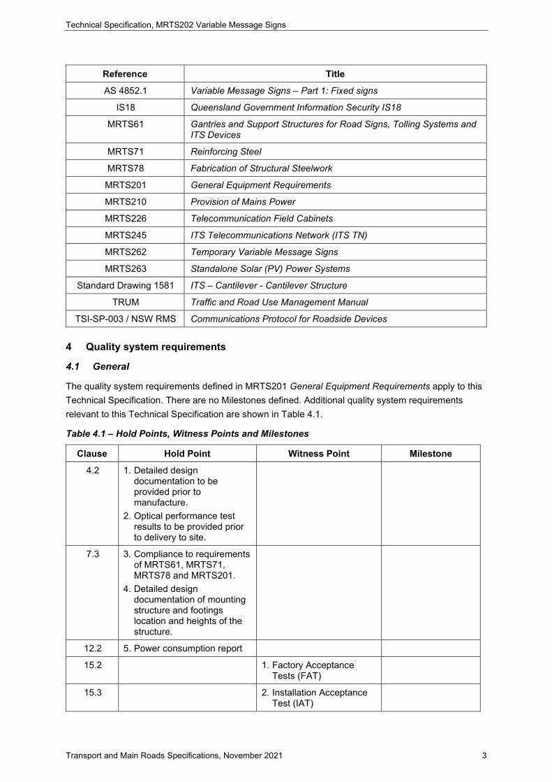
Table 4.1 – Hold Points, Witness Points and Milestones
Clause Hold Point Witness Point Milestone
4.2 1. Detailed design documentation to be provided prior to manufacture.
2. Optical performance test results to be provided prior to delivery to site.
7.3 3. Compliance to requirements of MRTS61, MRTS71, MRTS78 and MRTS201.
4. Detailed design documentation of mounting structure and footings location and heights of the structure.
12.2 5. Power consumption report
15.2 1. Factory Acceptance Tests (FAT)
15.3 2. Installation Acceptance Test (IAT)

Technical Specification, MRTS202 Variable Message Signs
Transport and Main Roads Specifications, November 2021 4
Clause Hold Point Witness Point Milestone
15.4 3. Commissioning Test (CT)
FAT, IAT and CT have been included in the quality system as Witness Points.
4.2 Sample variable message sign
Requirements of MRTS201 General Equipment Requirements apply to this Technical Specification. Detailed design of the sign layout, fabrication and assembly drawings, calculations, specifications and certifications of the VMS components (signed by the Contractor’s RPEQ) shall be submitted to the Principal for verification prior to manufacture.
These components include the VMS controller, sign face, LEDs, LED matrix boards, pixel arrangements showing horizontal and vertical pitch and total number of pixels, power supply (including surge protection and back-up batteries), communication ports, cable termination, enclosure and mounting accessories. Hold Point 1
Test certificates from a NATA accredited or NATA endorsed by Mutual Recognition laboratory, shall be submitted confirming that optical performance requirements of the VMS specified in this Technical Specification is complied with. Test certificates shall be submitted before the VMS is delivered to site. Test certificate shall have reference to the version of the optical module tested and shall be issued to the current version of the optical modules used in the VMS. Modifications of design of the optical modules such as change of LEDs, LED drivers requires the optical performance retested. Hold Point 2
As specified in MRTS201 General Equipment Requirement, a sample VMS shall be made available for the FAT.
4.3 Warranty
The Contractor installing the VMS shall warrant the installation against defects for a minimum of five years in accordance with the requirements of MRTS201 General Equipment Requirement.
Minimum five year warranty provision is required for electronic signage as they fall under a category of products which are high cost, safety critical or high quantity.
5 Functional requirements
5.1 General
The overall functions of the VMS are described in the Austroads Guide to Traffic Management Part 10. The Queensland specific requirements are supplemented as Queensland practice variations in the TRUM Part 10 Traffic Control and Communication Devices.
It shall be possible to monitor and control the VMS by TMS via a single VMS controller.

Technical Specification, MRTS202 Variable Message Signs
Transport and Main Roads Specifications, November 2021 5
5.2 Control methods
The VMS message shall be controlled by following methods using the VMS controller:
1. Locally, when the VMS controller has been selected for LOCAL operation using a local facility switch and/or hardwired inputs to select one of the pre-determined messages
2. Locally, when the VMS controller has been selected for MAINTENANCE operation via the PHCS.
3. Remotely by the TMS when the VMS controller has been selected for REMOTE operation. This shall be the normal mode of operation.
5.3 VMS controller
VMS controller shall:
• monitor, log and support TMS requests for operation and status
• store up to 255 frames in its non-volatile memory for the DU
• allow local automatic reset of the VMS display and the VMS controller itself such as via watchdog(s)
• allow integration of radar vehicle detectors to activate VMS display, only when vehicles are present in the viewing range of the sign
• be capable of dimming the connected signs based on the average of the light sensor outputs, and
• check validity of commands made by TMS and/or PHCS.
Additional information and functionality of the VMS controller required is described in the following sections.
5.4 Communications timeout
The VMS controller shall monitor loss of communications with the TMS and timeout after a specified period. When the VMS controller is in the REMOTE mode, expiry of this period shall cause the VMS controller to blank the entire VMS. The period shall be a configurable parameter. The VMS controller shall also be capable of monitoring communications with each DU and timeout after a specified period when such communication is lost. Communications timeout check shall be performed periodically and shall be a configurable parameter. In LOCAL mode, the communications timeout check with the TMS shall be ignored. Configuration parameters are shown in Appendix A.
Default values and permissible range of values are listed in this standard (Appendix A) to enable testing and configuration as required.
5.5 Configuration management
All settings in the VMS controller shall be accessible using the PHCS.
5.6 Sign fault management
The VMS controller shall monitor and log the following conditions:
• loss of communication with the FP and each DU

Technical Specification, MRTS202 Variable Message Signs
Transport and Main Roads Specifications, November 2021 6
• high enclosure temperature
• illumination faults, and
• other faults relating to the VMS.
The log shall identify the DU and its respective fault.
5.7 Local event logging
The VMS controller shall log in non-volatile memory, operational and fault events such as message changes, hardware resets, establishment or discontinuation of communications, local manual operations and clearance of faults. Each event shall be date and time stamped. Once a fault has occurred and been logged, a recurrence of the same fault need not be logged again until after the fault has been cleared.
The event log shall have space for at least 1,000 entries. Where separate logs are used for operational and fault events, each log shall have space for at least 1,000 entries. The oldest event record shall be overwritten first when this allocated space has been exceeded.
All log entries shall be available for upload from all communication ports upon request from the TMS and/or PHCS. The log shall be uploaded in order of most recent to oldest record. A request by the TMS for the event log shall provide for no less than 20 entries at a time.
Events shall be retained in the log even after retrieval by the PHCS and/or TMS.
5.8 Watchdog
The VMS controller and the DU shall monitor the state of its respective processor and blank the respective display/s if processor failure occurs.
5.9 Time synchronisation
The VMS controller shall be provided with an internal system clock in accordance with MRTS201 General Equipment Requirements. VMS shall synchronize it's time with TMS periodically.
6 VMS configuration options
VMS shall operate in either of the following configuration options.
1. A VMS capable of displaying 3 lines of 18 characters per line as specified in AS 4852.1 Section 5.1.2 Display dimensional requirements. The sign shall be capable of displaying pictograms/graphics in the entire area or sectionalised portion of the display in compliance with the Austroads Guide to Traffic Management Part 10.
2. A VMS capable of displaying 3 lines with the exception of only 8 characters per line compliant to AS 4852.1 Section 5.1.2 Display dimensional requirements. The sign shall be capable of displaying pictograms/graphics in the entire area or sectionalised portion of the display in compliance with the Austroads Guide to Traffic Management Part 10.
The VMS shall also include a VMS controller, FP, mounting structure, a telecommunications field cabinet, a switchboard and associated infrastructure/equipment complied with the requirements of this specification and/or relevant other specifications.

Technical Specification, MRTS202 Variable Message Signs
Transport and Main Roads Specifications, November 2021 7
7 Mechanical and physical requirements
The mechanical and physical requirements defined in MRTS201 General Equipment Requirements and MRTS61 Gantries and Support Structures for Road Signs, Tolling Systems and ITS Devices apply to work provided under this Technical Specification. Additional mechanical and physical requirements for equipment provided under this Technical Specification are described below.
7.1 Design life
Unless otherwise specified, the design life of the VMS components shall be in accordance with Clause 2.2 of AS 4851.1.
7.2 Display enclosure
The sign enclosure shall house the DU and associated control electronics and comply with the requirements of MRTS201 General Equipment Requirements. The sign enclosure shall be made of Marine Grade Aluminium compliant to AS 4852.1 Clause 3.1.1.
7.3 Mounting structure
The location and type of mounting structure to be provided to mount each VMS shall be shown on the design documentation. The mounting structure shall comply with the requirements of, MRTS61 Gantries and Support Structures for Road Signs, Tolling Systems and ITS Devices, MRTS71 Reinforcing Steel, MRTS78 Fabrication of Structural Steelwork and MRTS201 General Equipment Requirements. Hold Point 3
The requirements in MRTS78 Fabrication of Structural Steelwork, relating to the use of a registered fabricator when fabricating mounting structures for VMS apply.
For Cantilever structures, refer to Standard Drawing 1581.
The final design documentation shall include details of the final footing design, location of the structure and the heights. Contractor shall not commence fabrication of the footing and support structure until that final design documentation has been accepted by the Administrator. Hold Point 4
7.4 Field cabinets
All telecommunications equipment including the FP and the VMS controller associated with the VMS shall be installed in a suitable roadside enclosure, being either:
• a ground mounted field cabinet complying with requirements of MRTS226 Telecommunication Field Cabinets, or
• an integral enclosure complying with the requirements of MRTS201 General Equipment Requirements installed on the VMS mounting structure.
If the VMS controller is located within its enclosure, installation of it in the roadside enclosure is not applicable.

Technical Specification, MRTS202 Variable Message Signs
Transport and Main Roads Specifications, November 2021 8
8 Variable message display requirements
8.1 General
Variable message displays shall utilise a series of pixels forming a dot matrix display system. A “full matrix” configuration shall be used to allow the display of pictograms, graphics as well as alphanumeric characters. The horizontal and vertical pitch of the pixels in the matrix shall be the same.
The variable message display pixels shall be in modules of a size capable of being removed and installed by hand via the rear access door(s).
8.2 Variable message display technology
The display technology shall be light emitting diode (LED). The display pixels may be formed by arranging one or more LEDs in a cluster to achieve the required luminance levels.
8.3 Failures
Facilities shall be included to detect failures within the display control system. The DU shall blank the display in the event of a sign processor fault. Time to blank shall be a configurable setting with ranges as given in Appendix A.
The DU shall monitor communications with the VMS controller and blank the displays if loss of communication experienced. The communications timeout period shall be a configurable setting.
The VMS controller shall be able to periodically detect the failure of any LED in the display even if the LEDs are required to be ‘off’ at the time of the periodic check. The display shall be blanked upon failure of equal or more than four contiguous pixels in either horizontal or vertical direction or failure of more than 20% of LEDs.
On power restoration after loss of power, the VMS shall become available for activation and remain blank until commanded by any one of the control methods. The power recovery delay time shall be configurable. At no time shall partial or incomplete frames be displayed.
The VMS controller shall allow the sign’s display to remain blank for a minimum time once the display has been blanked irrespective of the cause. This minimum blank time shall be configurable.
Single LED failure, provided that the cumulative LED loss remains below the four contiguous and/or 20% thresholds described above or VMS light sensor failure, should not result in blanking of the display. The failure of any LED shall be reported in the log.
If colours are generated with a colour mixing technology from a cluster of LEDs, failure of any LED within the cluster shall automatically turn off the entire cluster to avoid generation of colour noise.
All configurable setting shall be as shown in Appendix A.
8.4 LED output
Each individual LED shall be driven with a continuous current with no peak and/or magnitudes exceeding 70% of the LED manufacturer's recommended maximum continuous rating.
8.5 Display Unit Requirements
Type A, Type B and Type C VMS shall comply with the display dimensional requirements of the AS 4852.1.

Technical Specification, MRTS202 Variable Message Signs
Transport and Main Roads Specifications, November 2021 9
Each alphanumeric character in the DU shall be formed by a matrix arrangement of horizontal and vertical pixels.
The signs shall have sufficient vertical pixels to permit lower case text, with descenders lie wholly below the base of the upper-case characters. The character format shall be complied with the requirements of the AS 4852.1.
Where specified by the principal VMS with characters per line of 8 is acceptable. However, all other display dimensional requirement of these VMS shall be complied with AS 4852.1.
VMS that is smaller in length, do not require larger structures to mount. These VMSs are suitable for providing information to motorists travel on rural motorways that service lower volumes of vehicles. Due to the short length of VMS, messages that can be displayed will be limited.
8.6 Display fonts
As a minimum, the variable message display shall generate single stroke alphanumeric character fonts generally to the requirements of AS 1742, AS 1743 and AS 1744. The characters shall be arranged to have a minimum of two pixels between characters and two pixels between lines.
8.7 Display changes
Variable message display changes shall be in accordance with the VMS use and operations guidelines stated in the Austroads Guide to Traffic Management Part 10. The Queensland specific requirements are supplemented as Queensland practice variations in the TRUM Part 10 Traffic Control and Communication Devices.
All display changes shall be effected by first blanking and then activating all required pixels of the respective display simultaneously (as visible to the eye).
8.8 Display colour
The VMS display shall be either be capable of displaying Monochrome (Yellow) or 4 Colour (Yellow, White, Red and Green) compliant with AS 4852.1 as follows.
1. VMS display shall be able to display individual pixels in Yellow against a matt Black background. LEDs shall be used within pixels to generate the output colour.
2. The VMS display shall be able to display individual pixels in either Yellow or White or Red or Green colours, against a matt Black background. LEDs shall be used within pixels to generate output colours. The individual pixels may generate colour with either discreate LED/s for each of the 4 colours or via a colour mixing arrangement with RGB LEDs or equivalent technologies. In the event of the use of colour mixing or equivalent technology, any non-compliant colours to AS 4852.1 shall neither be configurable nor displayed under any circumstances.
The VMS display's colours shall remain within their corresponding chromaticity coordinates, as specified in the Section 5.2.4 of AS 4852.1, for every configurable brightness level. The sign’s display colours shall remain within their corresponding specified chromaticity coordinates for at least 10 years of pixel service life specified in the Section 5.1.1.4 of AS 4852.1. It should be noted that this requirement is additional to the warranty requirements outlined in the Clause 4.3.

Technical Specification, MRTS202 Variable Message Signs
Transport and Main Roads Specifications, November 2021 10
8.9 Fall-back displays
Fall-back for VMS shall be blanked display unless otherwise specified.
8.10 Conspicuity devices
Conspicuity devices shall be provided as specified in AS 4852.1.
8.11 Optical performance
8.11.1 Luminance
The luminance and luminance ratio of the LED shall comply with the requirements of AS 4852.1.
8.11.2 LED dimming
The LED intensity shall be controlled to provide maximum legibility distances for the complete range of ambient light under which the VMS shall operate.
A VMS shall have a minimum of 16 LED brightness levels. The brightness levels shall be in units of percentage of maximum brightness. The transition between different brightness level shall not cause sudden changes in brightness. The transition time between two consequent brightness levels shall be configurable. The range of values and default value shall be as per Appendix A
The intensity of the conspicuity devices shall be controlled by the same system that controls the intensity of the LED displays.
8.11.3 Luminance intensity half angle
The luminance intensity half angle shall comply with the requirements of AS 4852.1.
8.11.4 Luminance intensity uniformity
Luminance intensity uniformity shall comply with the requirements of AS 4852.1.
8.11.5 Sun phantom
The action of sunlight or other bright light sources on the optical elements shall be controlled such that inactive pixels shall not appear active.
9 Control system
The control system requirements defined in MRTS201 General Equipment Requirements apply to this Technical Specification. Additional control system requirements for equipment provided under this specification are described below.
9.1 General
Each VMS shall be operated by an integral control system that is controlled in the following order of priority:
1. local facility switch
2. hardwired input(s)
3. maintenance communications port using the PHCS, and
4. control communications ports through either PHCS or Principal's host control system.
PHCS shall be provided in accordance with this specification.

Technical Specification, MRTS202 Variable Message Signs
Transport and Main Roads Specifications, November 2021 11
9.2 Local facility switch
A 4-position key operated facility switch that complies with MRTS201 General Equipment Requirements, shall be provided to enable selection of the following five display functions for each of the text display and the graphics display:
• OFF – display blank; control via all communications ports inhibited; status and diagnostic commands via all communications ports remain functional
• Normal – display active; displayed message selected via the maintenance communications port and/or the control communications port, and
• Message 1, Message 2 – display either message 1 or 2; control via all communications ports inhibited; status and diagnostic commands via all communications ports remain functional.
9.3 Maintenance communications port
It shall be possible to control and interrogate the VMS via a 10/100 base-T Ethernet maintenance communications port via the VMS controller. Ethernet port shall allow local and remote communications via a commercially available laptop computer installed with PHCS software. The maintenance communications port shall also allow remote connection of a similar computer via Principal's communications network.
When the PHCS is connected and operating, the VMS controller shall automatically change to 'MAINTENANCE' mode. Termination of the PHCS session shall enable TMS to control the VMS.
9.4 Control communications port
It shall be possible to control and interrogate the VMS via either of two TIA/EIA RS-422 or 10/100 base-T Ethernet control communications ports. The control communications ports shall allow local connection of a field processor/ modem for communications with TMS.
While a PC / laptop computer is connected and PHCS session is active to the VMS via the maintenance communications port, control of the VMS via the control ports shall be inhibited. However, status and diagnostic interrogation by STREAMS via the control ports shall remain possible.
Complete control and monitoring by STREAMS shall be possible through both control communications ports as determined by telecommunications infrastructure provided at each Site.
Where communications equipment is connected to both control communications ports, the primary port shall be used for control commands to / from the VMS, and the secondary port shall be used for status-only communications with the VMS.
Where communications equipment is connected to only one control communications port (or in the case of failure of either communications port or attached equipment) the VMS shall automatically revert to full control AND status communications through the active port.
VMS communications software shall be capable of operating at all possible modem connection and/or serial/Ethernet port speeds.
9.5 Control / diagnostics software
The VMS shall be capable of connection to the Principal's TMS, STREAMS, for remote control of the sign.

Technical Specification, MRTS202 Variable Message Signs
Transport and Main Roads Specifications, November 2021 12
The VMS shall be provided with manufacturers host control system (the PHCS) that includes additional functions for diagnostic of faults, by local and remote control of VMS.
The PHCS shall report the selected position of the facility switch.
9.5.1 Security and compatibility
The security requirements defined in MRTS201 General Equipment Requirements apply to this Technical Specification.
In addition, the software shall:
• Request passwords as part of the access and configuration authorisation process. Passwords shall be generally in accordance with IS18.
• Provide two access levels, namely, Administrator and Standard user, as a minimum.
• Be compatible with Microsoft Windows operating system environment, Windows 10, Windows 11, and those industry standards current at the time of delivery.
• Any software provided shall be capable of operating on all such operating systems.
• Be backward compatible with existing VMS purchased from the same manufacturer.
The factory default user credentials shall not be used, and these shall be changed prior to any operation of the VMS. Passwords shall be generally in accordance with IS18.
9.5.2 Configuration settings and firmware
The VMS configuration parameters can be set up locally or remotely. When set up remotely, the sign control shall provide a prompted warning to avoid losing connection unintentionally. The VMS shall have sufficient storage capacity to accommodate future firmware upgrades during the lifetime of the VMS. Storage capacity wise, no further hardware upgrades shall be required to accommodate ongoing firmware changes / upgrades. In addition, the configuration parameters shall be completely protected during software / firmware upgrade.
This requirement is necessary to ensure that software upgrades do not affect the existing configuration parameters or new software released by the manufacturer are compatible with existing VMS by the same manufacturer.
9.6 Hardwired inputs
The VMS controller shall have the ability to display a predefined message when it receives a voltage free contact closure or similar input from an external device such as a loop detector or vehicle over-height detector.
The VMS controller shall be capable of accepting a minimum of six hardwired inputs.
9.7 Message hierarchy
Each VMS controller shall provide a user-configurable message hierarchy for message selection commands and hardwired inputs.

Technical Specification, MRTS202 Variable Message Signs
Transport and Main Roads Specifications, November 2021 13
9.8 LED intensity control
The LED intensity shall be controlled to provide constant apparent brightness, and maximum legibility distance, for the complete range of ambient light under which the VMS shall operate.
Each VMS shall support automatic brightness variation, where the VMS determines the LED brightness level using a light sensor reading and a predefined set of light sensor values.
Each VMS shall be provided with at least two light sensors to detect ambient light levels. These sensors shall be located as follows:
• One sensor facing forward perpendicular to the sign face, and
• One sensor facing backward perpendicular to the sign face.
9.8.1 Time-of-Day intensity settings
The VMS controller shall provide means of adjusting the VMS brightness by time-of-day.
In the event of failure of the light sensors, seasonally adjusted time-of-day values stored in the group controller shall be used to adjust the VMS brightness.
9.9 Temperature control
Each VMS shall be provided with at least one temperature sensor to measure the temperature inside the display enclosure near the top centre and if required a cooling system consisting of cooling devices and thermostats.
Each thermostat shall operate the connected cooling device(s) once the internal ambient temperature (measured at the top of the cabinet) reaches the set point. The thermostat set point (TSP) is a configurable parameter as shown in Appendix A.
The temperature sensor shall not be mounted directly against the top face of the display enclosure. The temperature reading shall be available with a protocol message via STREAMS. The temperature shall be in units of degrees Centigrade. Upon failure of the VMS cooling system, the TMS shall shut down the sign if the temperature reaches a set value.
Furthermore, a configurable early warning temperature setting prior to its' shut down temperature level is required for efficient management of VMS. Both Thermostat High Temperature Shut Down Set Point (TSDSP) and Thermostat High Temperature Early Warning Set Point (TEWSP) shall be configurable, as shown in Appendix A.
9.10 Communication protocol
Communication between the Field Processor and the VMS shall comply with RMS protocol TSI-SP-003 Version 2.1 with colour extensions or other protocol accepted by the Principal's representative and the requirements of MRTS201 General Equipment Requirements.
New communication protocols such as NTCIP 1203 or TSI-SP-003 Version 5.0 are under consideration to support higher resolution dynamic message signs. However, these protocols are not in the scope of this specification at this stage. These additional protocol options may be included in the future versions of this Technical Specification.

Technical Specification, MRTS202 Variable Message Signs
Transport and Main Roads Specifications, November 2021 14
9.11 Bus arbitration
Each VMS shall act as a slave on the TIA/EIA RS-422 modem bus.
9.11.1 Display controls
When a standalone power system such as solar power is used to power the VMS, a display control mechanism shall be provided to activate the VMS display only when a vehicle is present within the viewing range of the VMS. The VMS shall display the full message prior to vehicle entering the viewing range and shall not deactivate the message until the vehicle has left the viewing range of VMS.
The VMS controller shall continuously communicate with the TMS at all times regardless of the status of the display. This facility shall be user configurable for setting up parameters such as enable/disable, and operational range.
10 Mechanical, physical and display enclosure requirements
10.1 General
The mechanical, physical and enclosure requirements defined in MRTS201 General Equipment Requirements apply to the display enclosure. Additional mechanical, physical and enclosure requirements for the display enclosure are described below.
10.2 Mounting
The display enclosure shall be capable of being mounted both on the verge and over the carriageway as defined in MRTS201 General Equipment Requirements.
Access doors shall be provided to allow access to the rear of the VMS for maintenance from the working platform on the mounting structure. The door arrangement shall be compatible with the mounting structure members. The mounting structure shall comply with MRTS201 General Equipment Requirements.
10.3 Exterior finish and surfaces
The surface finishes shall be compliant to AS 4852.1 Section 3.1.2 with external front face matt black and other external surfaces matt grey. Any interior surfaces that may be visible from outside the sign shall be matt black.
10.4 Weather resistance
The display enclosure shall provide a degree of protection of not less than that required for the classification of IP65 in accordance with AS 1939, in normal service.
Alternatively, the VMS shall have degree of protection of IP65 in accordance with AS 1939 at the modular level. The connections between the modules shall not compromise the degree of protection below IP65. This option may allow for the removal of polycarbonate see through front cover from the enclosure, thus reducing the display optical losses facilitating the use of low power LEDs. However, this approach shall not degrade the performance and design life of the VMS.
10.5 Equipment racks
Where required, the display enclosure and/or the control cabinet shall incorporate a standard 19-inch racking system to facilitate installation of all equipment requiring rack-mounting. The height of the racks shall be sufficient for the installation of all such equipment.

Technical Specification, MRTS202 Variable Message Signs
Transport and Main Roads Specifications, November 2021 15
10.6 Front cover
Where required to meet the weather resistance requirements, a see-through front cover shall be provided.
Front cover is not required if the sign design provided the weather resistance protection at modular level as stipulated in this Technical Specification.
10.6.1 Front cover material
The front cover material shall be a single, clear Lexan® polycarbonate sheet, or equivalent, with UV resistant and non-reflective finish. The sheeting shall be manufactured from sign-grade material SG300 with a thickness at least equal to that recommended by the manufacturer, and in all cases, at least 4.5 mm.
10.6.2 Viewing angles
The viewing window shall not obstruct sign viewing angles of ± 45° (horizontal) and ± 30° (vertical) to the axis perpendicular to the front plane of the display when installed at site.
10.6.3 Retention method
Front cover shall be able to be removed for maintenance from outside the VMS without requiring removal of internal components. Fasteners and retaining cover strips shall be easily accessible.
Front cover retention and seal design shall allow for thermal expansion properties of the front cover material. The front cover surrounding framework and cover strips shall provide the required weather proofing and strength for both positive and negative wind pressures.
10.7 Demister
A demister or an alternative method shall be provided to prevent condensation on the inside surface of the front cover if the front cover is part of the VMS design.
11 Environmental
The environmental conditions defined in MRTS201 General Equipment Requirements apply to this Technical Specification.
12 Electrical
The electrical requirements defined in MRTS201 General Equipment Requirements and AS 4852.1 apply to this Technical Specification. Additional requirements are as described below.
12.1 Power source
VMS shall be supplied with mains power in compliance with MRTS210 Provision of Mains Power or with a standalone power system compliance with MRTS263 Standalone Solar (PV) Power Systems. The sign except the display shall operate for 12 hours using a backup power system during a failure of mains power supply for TMS to monitor, log and diagnose the fault.
When powered by a standalone power system, it shall have an autonomy time of four days.
The signs that are powered through the stand-alone power systems shall have alarms set up for backup battery system to provide advance warnings to the TMS.

Technical Specification, MRTS202 Variable Message Signs
Transport and Main Roads Specifications, November 2021 16
12.2 Power consumption
The VMS supplier shall provide the power consumption details of the sign measured and recorded as follows;
• measuring instruments shall have a current calibration certificate issued by the manufacturer
• two readings shall be recorded for the minimum and maximum dimming levels
• VMS shall display message "REPORT TRAFFIC INCIDENT", with conspicuity devices flashing while the measurements are being taken, and
• if the VMS has any other sub-systems that consume power, they shall be active while power measurements are being taken.
A report shall be submitted with details of power consumption together with copies of calibration certificates of the measuring instruments. Hold Point 5
13 Installation requirements
The installation requirements defined in MRTS201 General Equipment Requirements apply to this Technical Specification. Where the sign controller resides in separate roadside cabinet, it must be placed at a location where the VMS face be visible. Consequently, ground-mounted cabinets should be located on the same side of the carriageway as the VMS. The cabinets shall comply with the requirements of MRTS201 General Equipment Requirements and MRTS226 Telecommunication Field Cabinets.
Location of the VMS shall comply with the requirements of the Austroads Guide to Traffic Management Part 10. Queensland practice variations are provided as a supplement in the TRUM Part 10 Traffic Control and Communication Devices. Further requirements are as detailed in the installation acceptance test and commissioning tests in this Technical Specification.
14 Telecommunications requirements
The telecommunications requirements defined in MRTS201 General Equipment Requirements and MRTS245 ITS Telecommunications Network (ITS TN) apply to work provided under this Technical Specification.
15 Testing and commissioning
15.1 General
The testing and commissioning requirements defined in MRTS201 General Equipment Requirements apply to work provided under this Technical Specification. The minimum additional testing and commissioning requirements for equipment provided under this Technical Specification are described below.
15.2 Factory acceptance tests (FAT)
The FAT shall include all the performance parameters in this Technical Specification that can be tested under laboratory/factory conditions.

Technical Specification, MRTS202 Variable Message Signs
Transport and Main Roads Specifications, November 2021 17
The optical performance, stated in this specification and to be conducted by a NATA accredited laboratory or NATA endorsed by Mutual Recognition laboratory, shall be determined by measurement under laboratory conditions of the minimum luminance ratio and the minimum and maximum luminance for the five sign illuminance levels listed in AS 4852.1 Table 5.5 in accordance with the test procedures defined therein – Appendix C – “Photometric Test Procedures”.
The colours for the red, green and yellow LEDs shall conform to the colours defined by the colour coordinates in AS 4852.1 Table 5.6, and Appendix D – “Colorimetric Test Procedures”. The optical performance of the VMS shall meet or exceed those quoted parameters. The optical performance report shall cover all parameters described in this specification. Witness Point 1
15.3 Installation acceptance tests (IAT)
Once the VMS is installed on site, the Contractor shall demonstrate and certify that the VMS has been installed to allow correct operation, exhibiting similar results in the intended operating environment as the results in the FAT. Witness Point 2
15.4 Commissioning tests (CT)
The commissioning requirements defined in MRTS201 General Equipment Requirements apply to work provided under this Technical Specification. The commissioning report sheet in Annexure MRTS202.1 shall be completed as part of the test and included in the operations manuals. Witness Point 3
A commissioning sheet has been included as part of Annexure MRTS202.1, listing parameters of significance for VMS commissioning.
16 Documentation
The documentation requirements defined in MRTS201 General Equipment Requirements apply to work provided under this Technical Specification.
17 Training
The training requirements defined in MRTS201 General Equipment Requirements apply to work provided under this Technical Specification.
18 Maintenance
The maintenance requirements defined in MRTS201 General Equipment Requirements apply to work provided under this Technical Specification.
19 Handover
The handover requirements defined in MRTS201 General Equipment Requirements apply to work provided under this Technical Specification. Further requirements are as described below.
The Contractor shall provide asset data for the installed VMS in the format prescribed in the QADF document. The Contractor will need to contact the Principal with regards to data requirements such as asset attributes specific to the project, as these requirements may change from project to project.

Technical Specification, MRTS202 Variable Message Signs
Transport and Main Roads Specifications, November 2021 18
20 Product Approval
Variable Message Signs can be proactively tested and be pre-approved for Department of Transport and Main Roads' deployments. The Product Approval checklist in spreadsheet form is published as Appendix B to this Technical Specification.

Technical Specification, MRTS202 Variable Message Signs
Transport and Main Roads Specifications, November 2021 19
Appendix A – Configuration Parameters
Table A – Configuration Parameters
Reference clause Description Range of values Factory default
Device(s), systems affected
5.4 TMS Communications Session Time-out
(STO)
1 - 600 seconds 300 seconds control unit/Configuration
Software
5.4 Communications check frequency (Controller
with sign display) (CST)
0 - 30 seconds Once every 5 seconds
control unit/sign display
5.4 Communication Timeout Setting
(Controller to Sign Display)
0 - 30 seconds 5 seconds control unit/sign display
5.6 Enclosure Over-Temperature Setting
(OTS)
0 – 70℃ in increments of 1℃
Max Alarm set at 42℃
control unit/sign display/enclosure
5.8 Sign processor fault blank time (PFBT)
0.5 – 3 seconds 1 second sign display
8.1 Flashing display elements setting
(FDES)
10 - 90% lit (1 s cycle time)
1 s cycle time 50% lit
Flashing display elements setting
(FDES)
8.3 Contiguous Pixel Failure (CPF)
0-10 4 control unit/sign display
8.3 Multi LED failure (MLEDF)
0 – 100% 20% control unit/sign display
8.4 Power recovery delay time (PRDT)
1 - 600 seconds 60 seconds control unit/sign display
8.4 Minimum blank time (MBT)
1 - 120 seconds 30 seconds control unit/sign display
8.11.2 LED brightness level transition time
1 – 60 seconds 15 control unit/sign
9.9 Thermostat High Temperature Shut
Down Set Point (TSDSP)
10 – 60℃ in increments of 1℃
ON at 50℃, OFF at 45℃
control unit/sign display/enclosure
Thermostat High Temperature Early Warning Set Point
(TEWSP)
10 – 60℃ in increments of 1℃
ON at 40℃ control unit/sign display/enclosure

Technical Specification, MRTS202 Variable Message Signs
Transport and Main Roads Specifications, November 2021 20
Appendix B – VMS Product Approval Checklist
Please see MRTS202 Variable Message Signs Technical Specification Appendix.