Embed Size (px)
Citation preview
R
TransNav Graphical UserInterface Reference Guide
TR4.0.x/TN5.0.x June 2011

Copyright © 2011 Force10 Networks, Inc.
All rights reserved. Force10 Networks ® reserves the right to change, modify, revise this publication without notice.
Trademarks
Force10 Networks® and E-Series® are registered trademarks of Force10 Networks, Inc.
Traverse, TraverseEdge, TraversePacketEdge, TransAccess, are registered trademarks of Force10 Networks, Inc. Force10, the Force10 logo, and TransNav are trademarks of Force10 Networks, Inc. or its affiliates in the United States and other countries and are protected by U.S. and international copyright laws. All other brand and product names are registered trademarks or trademarks of their respective holders.
Statement of Conditions
In the interest of improving internal design, operational function, and/or reliability, Force10 Networks, Inc. reserves the right to make changes to products described in this document without notice. Force10 Networks, Inc. does not assume any liability that may occur due to the use or application of the product(s) described herein.
CONTENTS
Chapter 1General Description of GUI Features TN5.0.x
Map View . . . . . . . . . . . . . . . . . . . . . . . . . . . . . . . . . . . . . . . . . . . . . . . . . . . . 2
Shortcut Menus for Map View . . . . . . . . . . . . . . . . . . . . . . . . . . . . . . . . . . . . 3
Traverse Shelf View . . . . . . . . . . . . . . . . . . . . . . . . . . . . . . . . . . . . . . . . . . . . 5
Shortcut Menus for Shelf View . . . . . . . . . . . . . . . . . . . . . . . . . . . . . . . . . . . 7
TE-100 Shelf View . . . . . . . . . . . . . . . . . . . . . . . . . . . . . . . . . . . . . . . . . . . . . 9
Shortcut Menus for TE-100 Shelf View . . . . . . . . . . . . . . . . . . . . . . . . . . . . . 10
Managing TE-206 Nodes from TransNav. . . . . . . . . . . . . . . . . . . . . . . . . . . . 12
EMS GUI Menus . . . . . . . . . . . . . . . . . . . . . . . . . . . . . . . . . . . . . . . . . . . . . . 13
File Menu . . . . . . . . . . . . . . . . . . . . . . . . . . . . . . . . . . . . . . . . . . . . . . . . . . . . 13
View Menu . . . . . . . . . . . . . . . . . . . . . . . . . . . . . . . . . . . . . . . . . . . . . . . . . . . 14
Admin Menu . . . . . . . . . . . . . . . . . . . . . . . . . . . . . . . . . . . . . . . . . . . . . . . . . . 15
Security Menu . . . . . . . . . . . . . . . . . . . . . . . . . . . . . . . . . . . . . . . . . . . . . . . . 17
Tools Menu. . . . . . . . . . . . . . . . . . . . . . . . . . . . . . . . . . . . . . . . . . . . . . . . . . . 18
Provisioning Menu . . . . . . . . . . . . . . . . . . . . . . . . . . . . . . . . . . . . . . . . . . . . . 19
Help Menu . . . . . . . . . . . . . . . . . . . . . . . . . . . . . . . . . . . . . . . . . . . . . . . . . . . 19
Node GUI Menus . . . . . . . . . . . . . . . . . . . . . . . . . . . . . . . . . . . . . . . . . . . . . . 20
GUI Conventions . . . . . . . . . . . . . . . . . . . . . . . . . . . . . . . . . . . . . . . . . . . . . . 23
Scroll Bars . . . . . . . . . . . . . . . . . . . . . . . . . . . . . . . . . . . . . . . . . . . . . . . . . . . 23
Resizing Capabilities . . . . . . . . . . . . . . . . . . . . . . . . . . . . . . . . . . . . . . . . . . . 23
Chapter 2Starting the Graphical User Interface
Starting the GUI from the Management Server . . . . . . . . . . . . . . . . . . . . . . . 2
Starting the GUI Application on a Windows Platform . . . . . . . . . . . . . . . . . . . 4
Starting the GUI Application on a Solaris Platform. . . . . . . . . . . . . . . . . . . . . 6
TransNav Client Workstation GUI User Login . . . . . . . . . . . . . . . . . . . . . . . . 8
Guidelines to Starting the Node-level GUI . . . . . . . . . . . . . . . . . . . . . . . . . . . 10
Install the Node-level GUI . . . . . . . . . . . . . . . . . . . . . . . . . . . . . . . . . . . . . . . 10
Starting the Node-level GUI Application on a Windows Platform. . . . . . . . . . 11
Node-level GUI User Login . . . . . . . . . . . . . . . . . . . . . . . . . . . . . . . . . . . . . . 13
Chapter 3Administration Procedures
Start the Server Administration Tool . . . . . . . . . . . . . . . . . . . . . . . . . . . . . . . 2
Initialize the Database . . . . . . . . . . . . . . . . . . . . . . . . . . . . . . . . . . . . . . . . . . 2
Enable the Server as a Service (Windows) . . . . . . . . . . . . . . . . . . . . . . . . . . 5
Start the Server . . . . . . . . . . . . . . . . . . . . . . . . . . . . . . . . . . . . . . . . . . . . . . . 5
TransNav Management System GUI Guide, Release TN5.0.x 1
Export (Backup) the Database . . . . . . . . . . . . . . . . . . . . . . . . . . . . . . . . . . . . 7
Stop the Server. . . . . . . . . . . . . . . . . . . . . . . . . . . . . . . . . . . . . . . . . . . . . . . . 11
Promoting a Secondary Server to the Primary Role. . . . . . . . . . . . . . . . . . . . 12
Disable Server as a Service (Windows) . . . . . . . . . . . . . . . . . . . . . . . . . . . . . 14
Disable DEP Service on Server (Windows) . . . . . . . . . . . . . . . . . . . . . . . . . . 15
Upgrade Server Software . . . . . . . . . . . . . . . . . . . . . . . . . . . . . . . . . . . . . . . . 18
Download the Management Software from the Force10 Website . . . . . . . . . 19
Import the Database . . . . . . . . . . . . . . . . . . . . . . . . . . . . . . . . . . . . . . . . . . . . 22
Configuring RADIUS Network Authentication. . . . . . . . . . . . . . . . . . . . . . . . . 24
Retrieve Server Log Files . . . . . . . . . . . . . . . . . . . . . . . . . . . . . . . . . . . . . . . . 27
Setting Up Report Parameters . . . . . . . . . . . . . . . . . . . . . . . . . . . . . . . . . . . . 28
Customizing Background Images for Map View . . . . . . . . . . . . . . . . . . . . . . . 31
Configuring DHCP . . . . . . . . . . . . . . . . . . . . . . . . . . . . . . . . . . . . . . . . . . . . . 33
Setting a Broadcast Message. . . . . . . . . . . . . . . . . . . . . . . . . . . . . . . . . . . . . 34
Terminating User Sessions in Bulk . . . . . . . . . . . . . . . . . . . . . . . . . . . . . . . . . 36
Setting Administrative Options . . . . . . . . . . . . . . . . . . . . . . . . . . . . . . . . . . . . 37
Restore Default Server Parameters . . . . . . . . . . . . . . . . . . . . . . . . . . . . . . . . 44
Chapter 4Managing Server Security
Definitions . . . . . . . . . . . . . . . . . . . . . . . . . . . . . . . . . . . . . . . . . . . . . . . . . . . . 1
Password Changes. . . . . . . . . . . . . . . . . . . . . . . . . . . . . . . . . . . . . . . . . . . . . 2
Guidelines to Managing Server Security. . . . . . . . . . . . . . . . . . . . . . . . . . . . . 3
Domain User Access Roles . . . . . . . . . . . . . . . . . . . . . . . . . . . . . . . . . . . . . . 4
Domain Users . . . . . . . . . . . . . . . . . . . . . . . . . . . . . . . . . . . . . . . . . . . . . . . . . 5
Functional Groups . . . . . . . . . . . . . . . . . . . . . . . . . . . . . . . . . . . . . . . . . . . . . 6
Session List . . . . . . . . . . . . . . . . . . . . . . . . . . . . . . . . . . . . . . . . . . . . . . . . . . 9
Chapter 5Managing Node Security
Definitions . . . . . . . . . . . . . . . . . . . . . . . . . . . . . . . . . . . . . . . . . . . . . . . . . . . . 1
Node User Access Roles . . . . . . . . . . . . . . . . . . . . . . . . . . . . . . . . . . . . . . . . 2
Node Users . . . . . . . . . . . . . . . . . . . . . . . . . . . . . . . . . . . . . . . . . . . . . . . . . . . 3
Chapter 6Using TransNav GUI with TN-Sight
Prerequisites. . . . . . . . . . . . . . . . . . . . . . . . . . . . . . . . . . . . . . . . . . . . . . . . . . 1
Access Roles on TN-Sight . . . . . . . . . . . . . . . . . . . . . . . . . . . . . . . . . . . . . . . 2
Provisioning TE-206 Nodes from TransNav . . . . . . . . . . . . . . . . . . . . . . . . . . 2
TE-206 Alarms and Events. . . . . . . . . . . . . . . . . . . . . . . . . . . . . . . . . . . . . . . 3
TE-206 Node Database Backup and Restore. . . . . . . . . . . . . . . . . . . . . . . . . 3
Removing TE-206 Nodes . . . . . . . . . . . . . . . . . . . . . . . . . . . . . . . . . . . . . . . . 3
Chapter 7Managing TE-206 Nodes from TransNav
2 TransNav Management System GUI Guide, Release TN5.0.x
Managing TE-206 Nodes from TransNav. . . . . . . . . . . . . . . . . . . . . . . . . . . . 2
Discovering TE-206 Nodes from TransNav . . . . . . . . . . . . . . . . . . . . . . . . . . 3
Chapter 8Administrating TE-206 Node Users from TransNav
Password Criteria . . . . . . . . . . . . . . . . . . . . . . . . . . . . . . . . . . . . . . . . . . . . . . 1
Determining TE-206 Node User Privileges . . . . . . . . . . . . . . . . . . . . . . . . . . 1
Synchronizing TE-206 Node Users . . . . . . . . . . . . . . . . . . . . . . . . . . . . . . . . 3
Chapter 9 TransNav User Preferences
Select Background Image for Map View . . . . . . . . . . . . . . . . . . . . . . . . . . . . 2
Saving and Importing User Preferences . . . . . . . . . . . . . . . . . . . . . . . . . . . . 3
Customize System Options . . . . . . . . . . . . . . . . . . . . . . . . . . . . . . . . . . . . . . 4
Grouping Nodes . . . . . . . . . . . . . . . . . . . . . . . . . . . . . . . . . . . . . . . . . . . . . . . 6
Changing Node Group Names . . . . . . . . . . . . . . . . . . . . . . . . . . . . . . . . . . . . 13
Chapter 10Generating and Viewing Reports
Generating Reports . . . . . . . . . . . . . . . . . . . . . . . . . . . . . . . . . . . . . . . . . . . . 1
Generating a PM Report . . . . . . . . . . . . . . . . . . . . . . . . . . . . . . . . . . . . . . . . 5
Using the Report Scheduler . . . . . . . . . . . . . . . . . . . . . . . . . . . . . . . . . . . . . . 6
Adding Customer Information. . . . . . . . . . . . . . . . . . . . . . . . . . . . . . . . . . . . . 8
Viewing Reports . . . . . . . . . . . . . . . . . . . . . . . . . . . . . . . . . . . . . . . . . . . . . . . 9
Example Report Output . . . . . . . . . . . . . . . . . . . . . . . . . . . . . . . . . . . . . . . . . 11
Removing Generated Reports . . . . . . . . . . . . . . . . . . . . . . . . . . . . . . . . . . . . 12
TransNav Management System GUI Guide, Release TN5.0.x 3

4 TransNav Management System GUI Guide, Release TN5.0.x
Chapter 1 General Description of GUI Features TN5.0.x
Introduction This chapter provides a description of the navigational components of the graphical user interface (GUI) for the TransNav management server and node-level GUI. From the EMS server interface, you can manage Traverse, TraverseEdge, and TransAccess nodes.
EMS GUI
Using the EMS GUI, you can view the network or domains you are managing (Map View) or any particular shelf (Shelf View). Context-sensitive tabs are available for the view selected.
The Map View displays all the nodes in a network and is the initial display when you start the GUI.
The Traverse Shelf View displays all the cards (modules) in a node and their associated ports.
The TE-100 Shelf Viewdisplays the shelf view for the TE-100.
Managing TE-206 Nodes from TransNav defines how TE-206 nodes can be managed from the TransNav EMS GUI.
For more information on the EMS GUI menu options, see EMS GUI Menus.
This chapter also describes the following GUI features, available on the EMS and Node-level GUIs: • GUI Conventions• Resizing Capabilities• Scroll Bars• Resizing Capabilities
Node-level GUI
Similar to the TransNav management system GUI, the Node-level graphical user interface (also called the Craft GUI) provides a shelf view of a Traverse node for easier maintenance. The Node-level GUI does not communicate with the TransNav server.
TransNav Management System GUI Guide, Release TN5.0.x 1
Any IP-based management connection can provide the communication path between the Node-level GUI and the Traverse system’s active GCM, including front-access craft Ethernet, Backplane Ethernet, DCC, and ECC.
Note: The Node-level GUI works only with Traverse nodes in this release. TE-100 and TE-206 nodes are not supported. The information in the Node-level GUI application is obtained directly from the Traverse platform. The Node-level GUI release must match the corresponding Traverse release.
For information on the Node-level GUI features, see Node GUI Menus.
Map View The tabs on the Map View allow you to view and change the following information.
Note: Map View is available on the EMS GUI only. • Alarms: Alarms on nodes in the domain. See the Operations and Maintenance
Guide, Chapter 2—“Managing Alarms.”• Events: Events on nodes in the domain. See the Operations and Maintenance
Guide, Chapter 3—“Managing Events.”• Config: Configuration information for the selected piece of equipment. • Protection: Define protected rings. See the TransNav Management System
Provisioning Guide, Chapter 2—“Protection Group Configuration.” • Performance: Monitor performance and VT/TU capacity data. See the Operations
and Maintenance Guide, Chapter 1—“Managing Performance.”• Service: Define services between nodes in a domain. See the TransNav
Management System Provisioning Guide, Chapter 1—“Service Provisioning Concepts.”
• Service Group: Configure a number of services into groups on the node. See the TransNav Management System Provisioning Guide, Chapter 4—“Service Groups.”
2 TransNav Management System GUI Guide, Release TN5.0.x
Shortcut Menus for Map View
Two shortcut menus are available in Map View: • Right-click a node• Right-click the background image
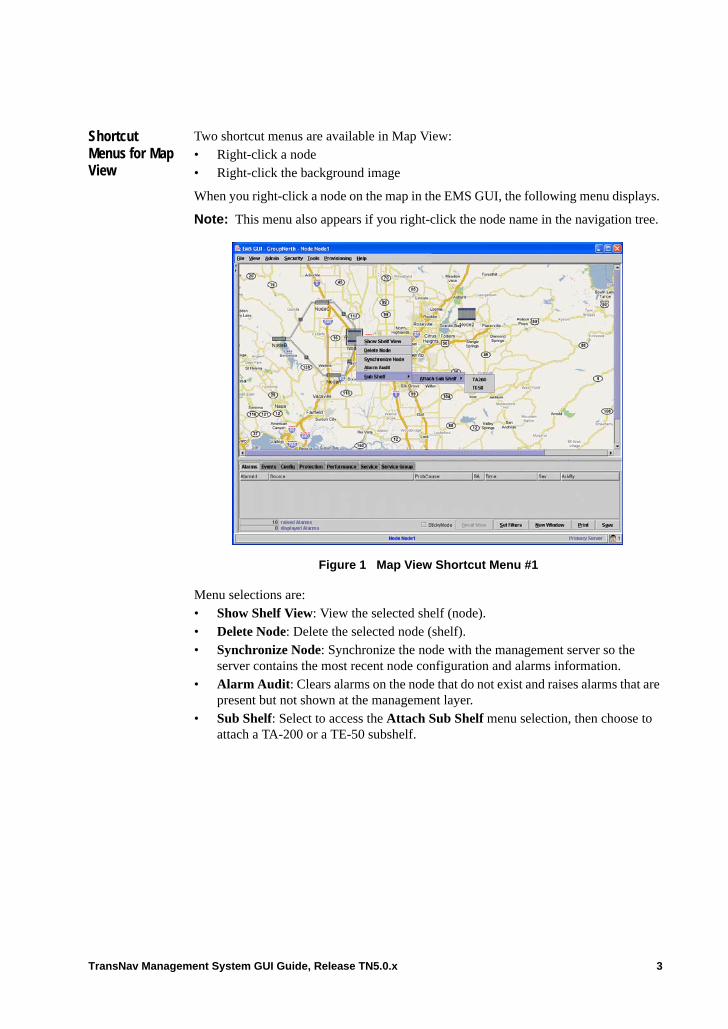
When you right-click a node on the map in the EMS GUI, the following menu displays.
Note: This menu also appears if you right-click the node name in the navigation tree.
Figure 1 Map View Shortcut Menu #1
Menu selections are:• Show Shelf View: View the selected shelf (node).• Delete Node: Delete the selected node (shelf).• Synchronize Node: Synchronize the node with the management server so the
server contains the most recent node configuration and alarms information.• Alarm Audit: Clears alarms on the node that do not exist and raises alarms that are
present but not shown at the management layer.• Sub Shelf: Select to access the Attach Sub Shelf menu selection, then choose to
attach a TA-200 or a TE-50 subshelf.
TransNav Management System GUI Guide, Release TN5.0.x 3
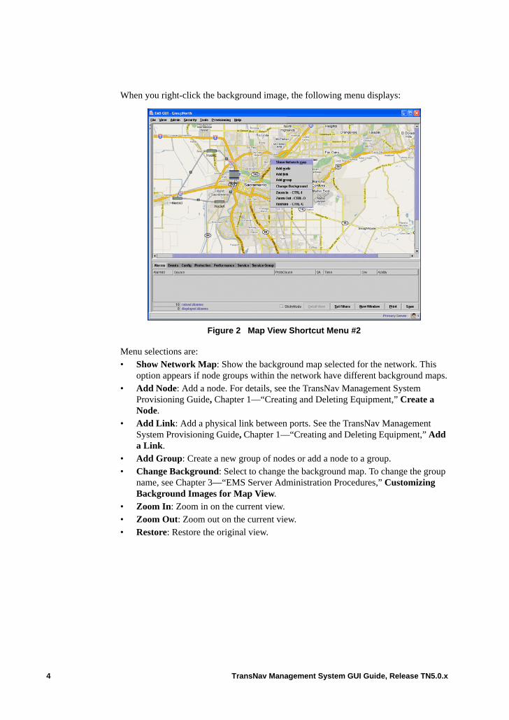
When you right-click the background image, the following menu displays:
Figure 2 Map View Shortcut Menu #2
Menu selections are:• Show Network Map: Show the background map selected for the network. This
option appears if node groups within the network have different background maps.• Add Node: Add a node. For details, see the TransNav Management System
Provisioning Guide, Chapter 1—“Creating and Deleting Equipment,” Create a Node.
• Add Link: Add a physical link between ports. See the TransNav Management System Provisioning Guide, Chapter 1—“Creating and Deleting Equipment,” Add a Link.
• Add Group: Create a new group of nodes or add a node to a group.• Change Background: Select to change the background map. To change the group
name, see Chapter 3—“EMS Server Administration Procedures,” Customizing Background Images for Map View.
• Zoom In: Zoom in on the current view.• Zoom Out: Zoom out on the current view.• Restore: Restore the original view.
4 TransNav Management System GUI Guide, Release TN5.0.x
Traverse Shelf View
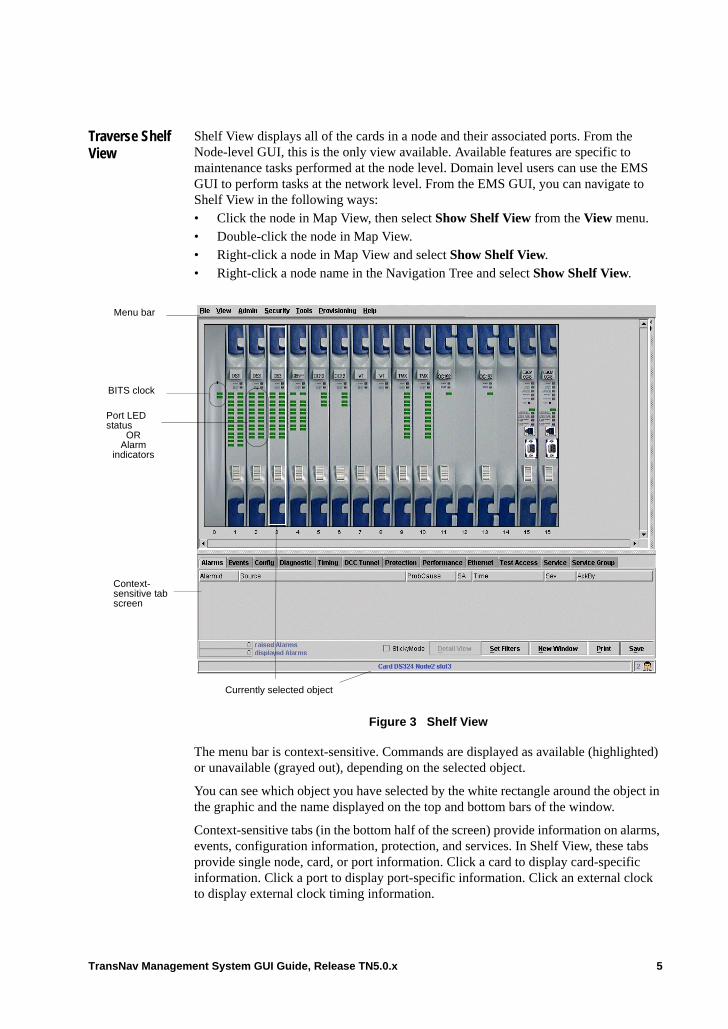
Shelf View displays all of the cards in a node and their associated ports. From the Node-level GUI, this is the only view available. Available features are specific to maintenance tasks performed at the node level. Domain level users can use the EMS GUI to perform tasks at the network level. From the EMS GUI, you can navigate to Shelf View in the following ways: • Click the node in Map View, then select Show Shelf View from the View menu.• Double-click the node in Map View.• Right-click a node in Map View and select Show Shelf View.• Right-click a node name in the Navigation Tree and select Show Shelf View.
Figure 3 Shelf View
The menu bar is context-sensitive. Commands are displayed as available (highlighted) or unavailable (grayed out), depending on the selected object.
You can see which object you have selected by the white rectangle around the object in the graphic and the name displayed on the top and bottom bars of the window.
Context-sensitive tabs (in the bottom half of the screen) provide information on alarms, events, configuration information, protection, and services. In Shelf View, these tabs provide single node, card, or port information. Click a card to display card-specific information. Click a port to display port-specific information. Click an external clock to display external clock timing information.
Currently selected object
Menu bar
BITS clock
Context-sensitive tab screen
Port LED status
ORAlarm
indicators
TransNav Management System GUI Guide, Release TN5.0.x 5
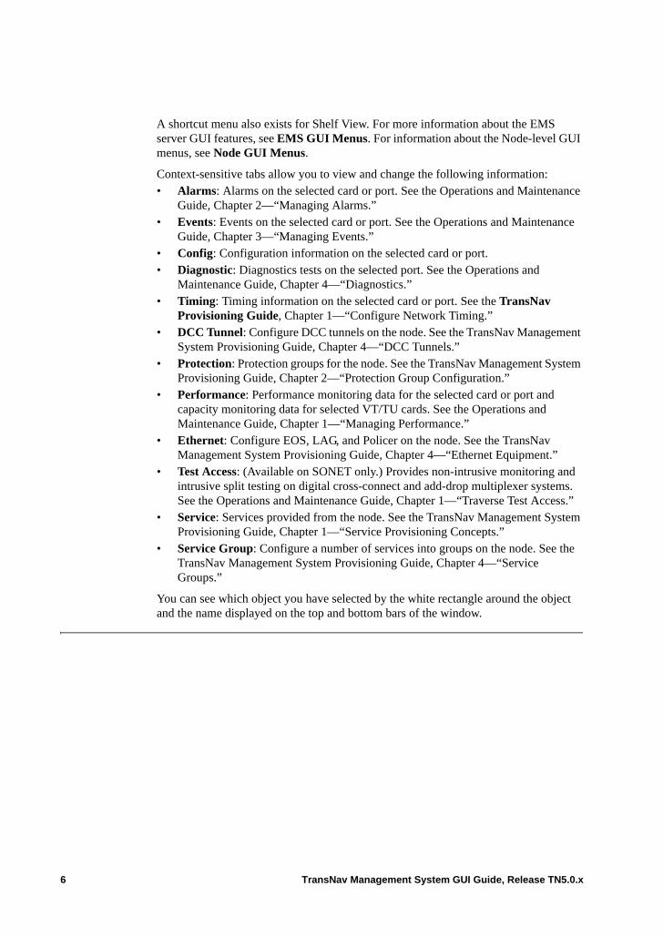
A shortcut menu also exists for Shelf View. For more information about the EMS server GUI features, see EMS GUI Menus. For information about the Node-level GUI menus, see Node GUI Menus.
Context-sensitive tabs allow you to view and change the following information:• Alarms: Alarms on the selected card or port. See the Operations and Maintenance
Guide, Chapter 2—“Managing Alarms.”• Events: Events on the selected card or port. See the Operations and Maintenance
Guide, Chapter 3—“Managing Events.”• Config: Configuration information on the selected card or port. • Diagnostic: Diagnostics tests on the selected port. See the Operations and
Maintenance Guide, Chapter 4—“Diagnostics.”• Timing: Timing information on the selected card or port. See the TransNav
Provisioning Guide, Chapter 1—“Configure Network Timing.”• DCC Tunnel: Configure DCC tunnels on the node. See the TransNav Management
System Provisioning Guide, Chapter 4—“DCC Tunnels.”• Protection: Protection groups for the node. See the TransNav Management System
Provisioning Guide, Chapter 2—“Protection Group Configuration.”• Performance: Performance monitoring data for the selected card or port and
capacity monitoring data for selected VT/TU cards. See the Operations and Maintenance Guide, Chapter 1—“Managing Performance.”
• Ethernet: Configure EOS, LAG, and Policer on the node. See the TransNav Management System Provisioning Guide, Chapter 4—“Ethernet Equipment.”
• Test Access: (Available on SONET only.) Provides non-intrusive monitoring and intrusive split testing on digital cross-connect and add-drop multiplexer systems. See the Operations and Maintenance Guide, Chapter 1—“Traverse Test Access.”
• Service: Services provided from the node. See the TransNav Management System Provisioning Guide, Chapter 1—“Service Provisioning Concepts.”
• Service Group: Configure a number of services into groups on the node. See the TransNav Management System Provisioning Guide, Chapter 4—“Service Groups.”
You can see which object you have selected by the white rectangle around the object and the name displayed on the top and bottom bars of the window.
6 TransNav Management System GUI Guide, Release TN5.0.x
Shortcut Menus for Shelf View
Two shortcut menus are available in Shelf View. • Right-click a slot not occupied by a card• Right-click a slot occupied by a card
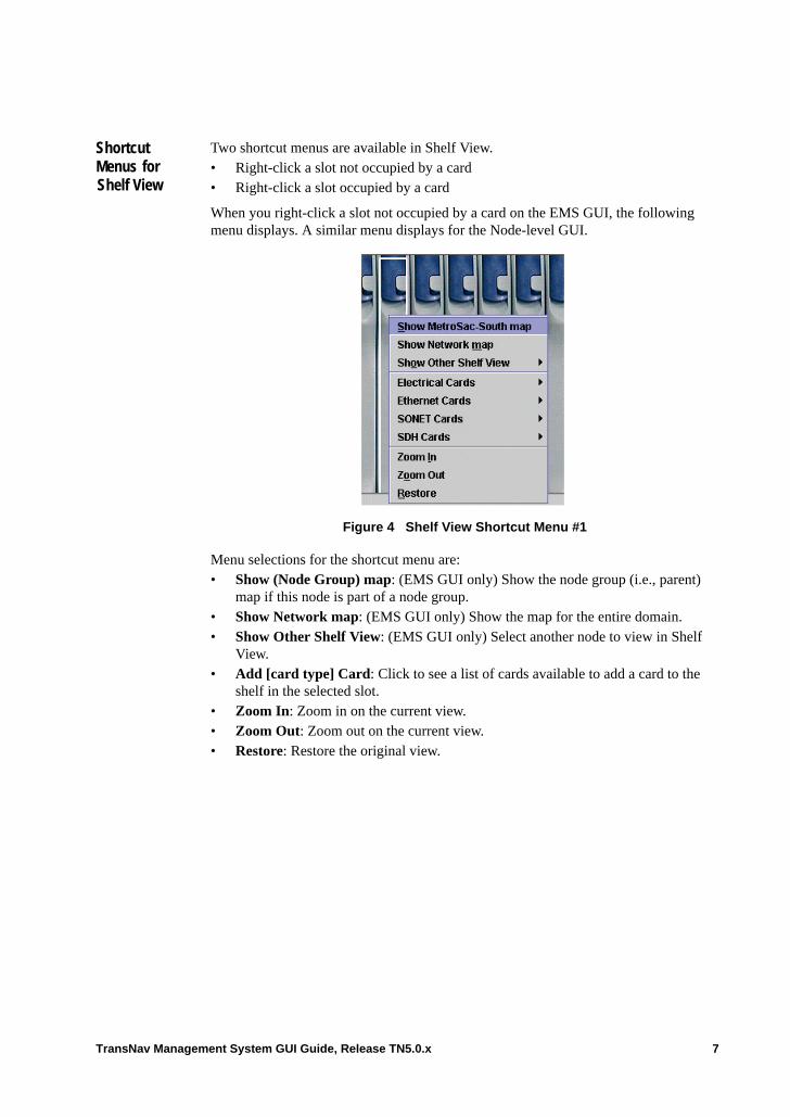
When you right-click a slot not occupied by a card on the EMS GUI, the following menu displays. A similar menu displays for the Node-level GUI.
Figure 4 Shelf View Shortcut Menu #1
Menu selections for the shortcut menu are:• Show (Node Group) map: (EMS GUI only) Show the node group (i.e., parent)
map if this node is part of a node group.• Show Network map: (EMS GUI only) Show the map for the entire domain. • Show Other Shelf View: (EMS GUI only) Select another node to view in Shelf
View.• Add [card type] Card: Click to see a list of cards available to add a card to the
shelf in the selected slot.• Zoom In: Zoom in on the current view.• Zoom Out: Zoom out on the current view.• Restore: Restore the original view.
TransNav Management System GUI Guide, Release TN5.0.x 7
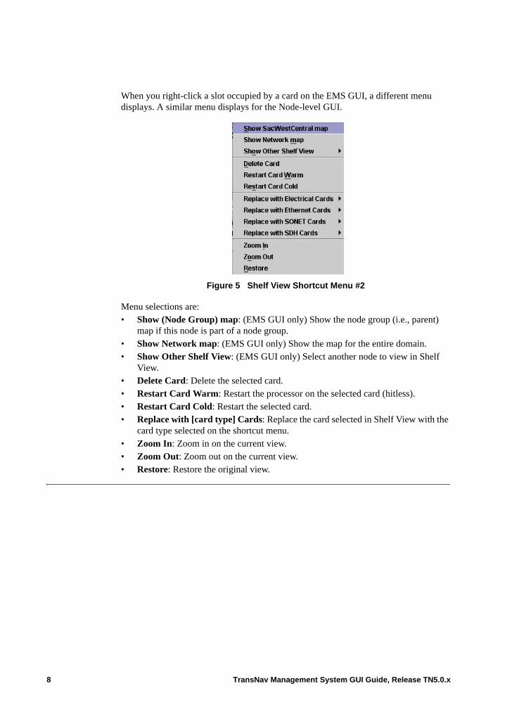
When you right-click a slot occupied by a card on the EMS GUI, a different menu displays. A similar menu displays for the Node-level GUI.
Figure 5 Shelf View Shortcut Menu #2
Menu selections are:• Show (Node Group) map: (EMS GUI only) Show the node group (i.e., parent)
map if this node is part of a node group.• Show Network map: (EMS GUI only) Show the map for the entire domain. • Show Other Shelf View: (EMS GUI only) Select another node to view in Shelf
View.• Delete Card: Delete the selected card.• Restart Card Warm: Restart the processor on the selected card (hitless).• Restart Card Cold: Restart the selected card.• Replace with [card type] Cards: Replace the card selected in Shelf View with the
card type selected on the shortcut menu.• Zoom In: Zoom in on the current view.• Zoom Out: Zoom out on the current view.• Restore: Restore the original view.
8 TransNav Management System GUI Guide, Release TN5.0.x
TE-100 Shelf View
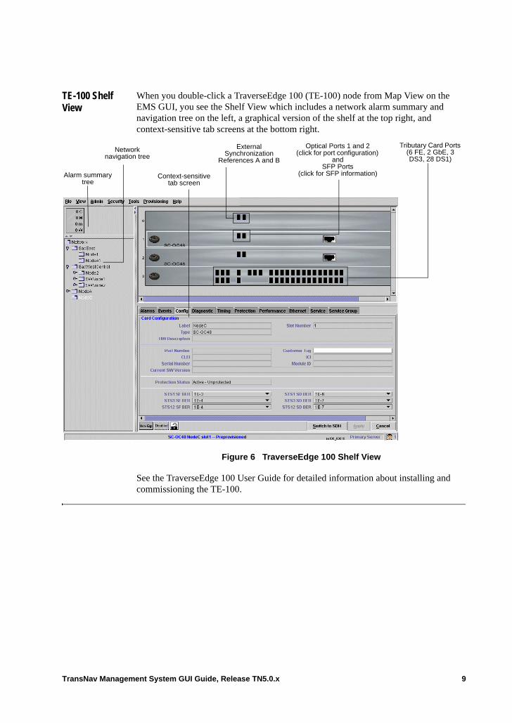
When you double-click a TraverseEdge 100 (TE-100) node from Map View on the EMS GUI, you see the Shelf View which includes a network alarm summary and navigation tree on the left, a graphical version of the shelf at the top right, and context-sensitive tab screens at the bottom right.
Figure 6 TraverseEdge 100 Shelf View
See the TraverseEdge 100 User Guide for detailed information about installing and commissioning the TE-100.
Alarm summary tree
Network navigation tree
Context-sensitive tab screen
Optical Ports 1 and 2 (click for port configuration)
and SFP Ports
(click for SFP information)
External Synchronization
References A and B
Tributary Card Ports (6 FE, 2 GbE, 3 DS3, 28 DS1)
TransNav Management System GUI Guide, Release TN5.0.x 9
Shortcut Menus for TE-100 Shelf View
Two shortcut menus are available in Shelf View: • Right-click a slot not occupied by a card• Right-click a slot occupied by a card
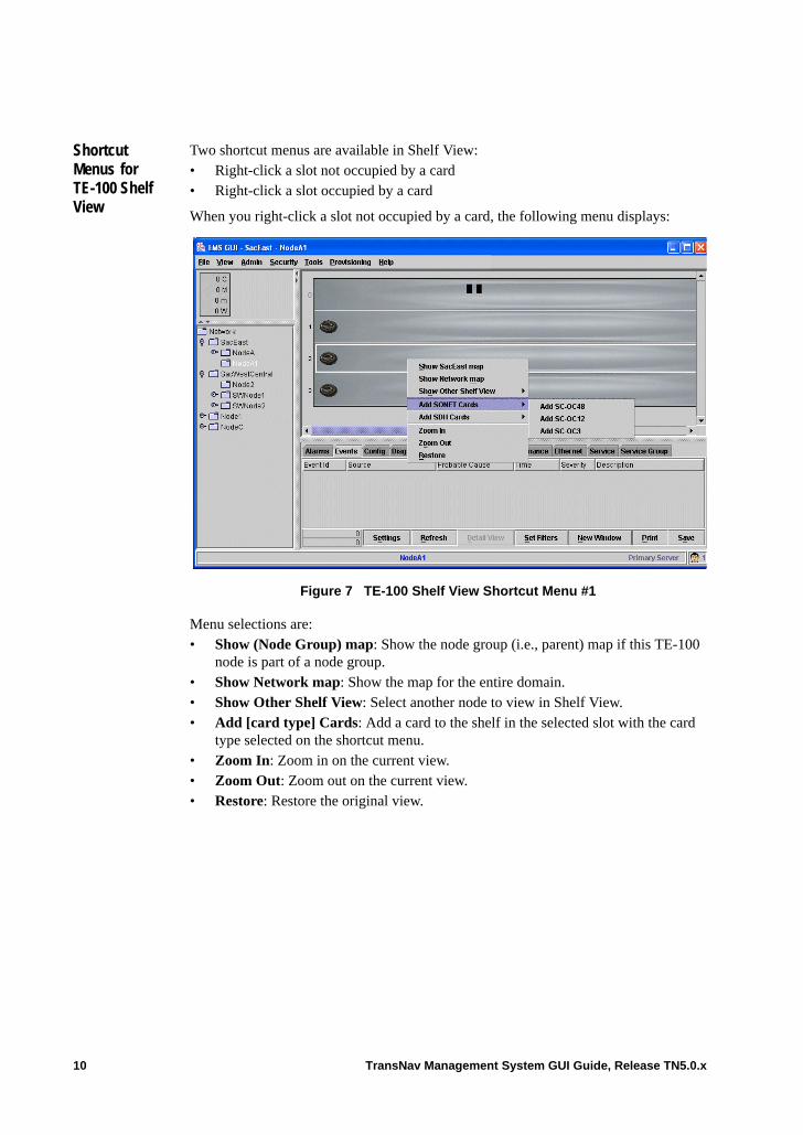
When you right-click a slot not occupied by a card, the following menu displays:
Figure 7 TE-100 Shelf View Shortcut Menu #1
Menu selections are:• Show (Node Group) map: Show the node group (i.e., parent) map if this TE-100
node is part of a node group.• Show Network map: Show the map for the entire domain.• Show Other Shelf View: Select another node to view in Shelf View.• Add [card type] Cards: Add a card to the shelf in the selected slot with the card
type selected on the shortcut menu. • Zoom In: Zoom in on the current view.• Zoom Out: Zoom out on the current view.• Restore: Restore the original view.
10 TransNav Management System GUI Guide, Release TN5.0.x
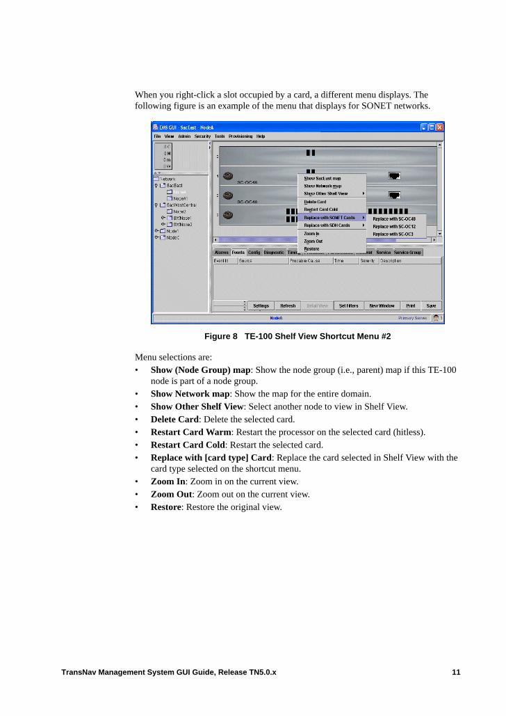
When you right-click a slot occupied by a card, a different menu displays. The following figure is an example of the menu that displays for SONET networks.
Figure 8 TE-100 Shelf View Shortcut Menu #2
Menu selections are:• Show (Node Group) map: Show the node group (i.e., parent) map if this TE-100
node is part of a node group.• Show Network map: Show the map for the entire domain.• Show Other Shelf View: Select another node to view in Shelf View.• Delete Card: Delete the selected card.• Restart Card Warm: Restart the processor on the selected card (hitless).• Restart Card Cold: Restart the selected card.• Replace with [card type] Card: Replace the card selected in Shelf View with the
card type selected on the shortcut menu.• Zoom In: Zoom in on the current view.• Zoom Out: Zoom out on the current view.• Restore: Restore the original view.
TransNav Management System GUI Guide, Release TN5.0.x 11
Managing TE-206 Nodes from TransNav
TransNav can be used to manage TraverseEdge 206 (TE-206) nodes as either standalone nodes or in a network ring.
If the TE-206 is a standalone node in the Traverse network, it can be discovered from the EMS GUI by selecting the Tools menu, then clicking Discovery and entering the node IP address. For more information, see Chapter 3—“Using TransNav GUI with TN-Sight,” Provisioning TE-206 Nodes from TransNav.
Each time a TE-206 node or link is added or removed from the network, use the Rediscovery option from the Tools menu to manually notify the EMS GUI to discover the changes.
Note: For interoperability with TE-206 nodes in the network, all TE-100 nodes must be upgraded to release TE3.2.3.
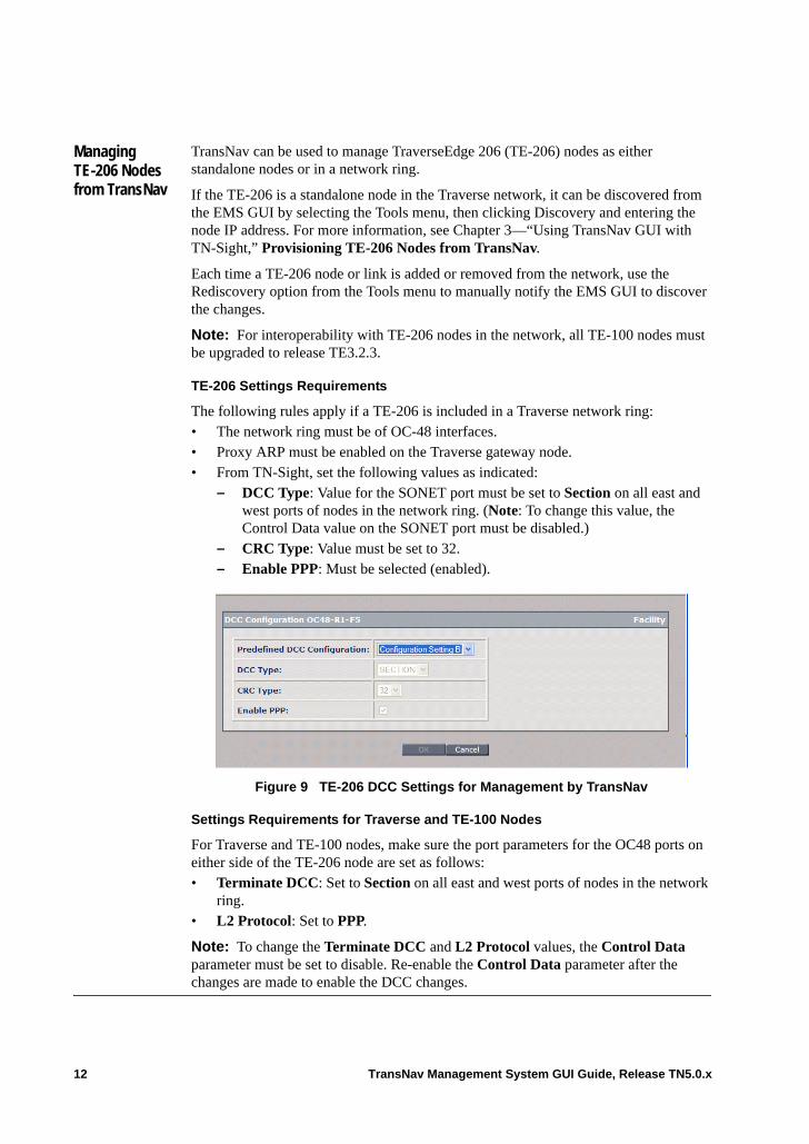
TE-206 Settings Requirements
The following rules apply if a TE-206 is included in a Traverse network ring: • The network ring must be of OC-48 interfaces. • Proxy ARP must be enabled on the Traverse gateway node.• From TN-Sight, set the following values as indicated:
– DCC Type: Value for the SONET port must be set to Section on all east and west ports of nodes in the network ring. (Note: To change this value, the Control Data value on the SONET port must be disabled.)
– CRC Type: Value must be set to 32.– Enable PPP: Must be selected (enabled).
Figure 9 TE-206 DCC Settings for Management by TransNav
Settings Requirements for Traverse and TE-100 Nodes
For Traverse and TE-100 nodes, make sure the port parameters for the OC48 ports on either side of the TE-206 node are set as follows: • Terminate DCC: Set to Section on all east and west ports of nodes in the network
ring. • L2 Protocol: Set to PPP.
Note: To change the Terminate DCC and L2 Protocol values, the Control Data parameter must be set to disable. Re-enable the Control Data parameter after the changes are made to enable the DCC changes.
12 TransNav Management System GUI Guide, Release TN5.0.x
EMS GUI Menus
Each menu in the EMS menu bar is context-sensitive. Items can be displayed as available (highlighted) or unavailable (grayed out) depending on the currently active object. The following sections summarize the available EMS GUI menu options:• File Menu, page 13• View Menu, page 14• Admin Menu, page 15• Security Menu, page 17• Tools Menu, page 18• Provisioning Menu, page 19• Help Menu, page 19
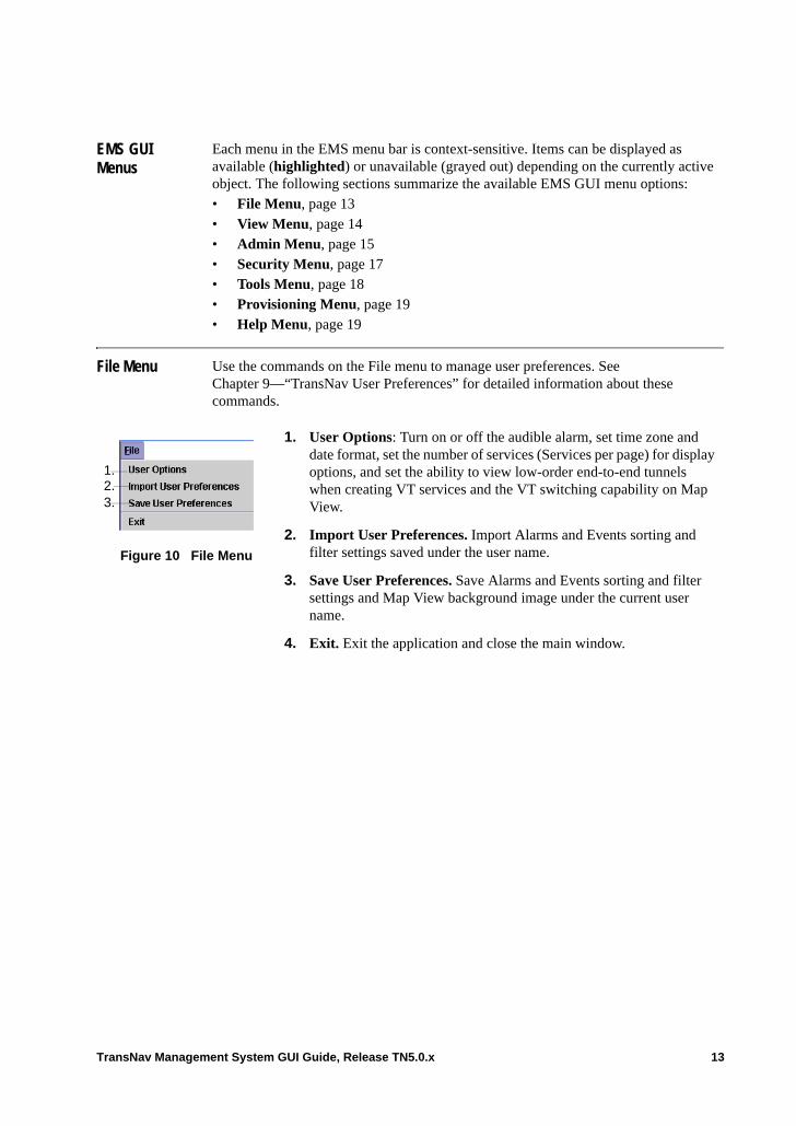
File Menu Use the commands on the File menu to manage user preferences. See Chapter 9—“TransNav User Preferences” for detailed information about these commands.
Figure 10 File Menu
1. User Options: Turn on or off the audible alarm, set time zone and date format, set the number of services (Services per page) for display options, and set the ability to view low-order end-to-end tunnels when creating VT services and the VT switching capability on Map View.
2. Import User Preferences. Import Alarms and Events sorting and filter settings saved under the user name.
3. Save User Preferences. Save Alarms and Events sorting and filter settings and Map View background image under the current user name.
4. Exit. Exit the application and close the main window.
1.2.3.
TransNav Management System GUI Guide, Release TN5.0.x 13
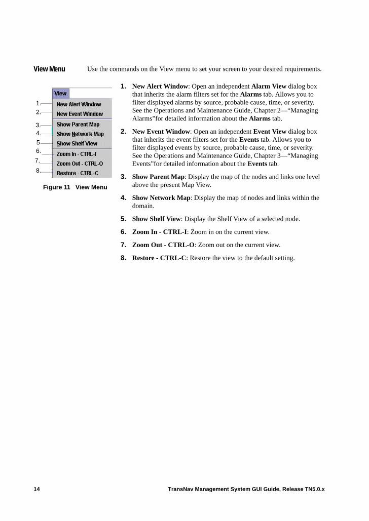
View Menu Use the commands on the View menu to set your screen to your desired requirements.
Figure 11 View Menu
1. New Alert Window: Open an independent Alarm View dialog box that inherits the alarm filters set for the Alarms tab. Allows you to filter displayed alarms by source, probable cause, time, or severity. See the Operations and Maintenance Guide, Chapter 2—“Managing Alarms”for detailed information about the Alarms tab.
2. New Event Window: Open an independent Event View dialog box that inherits the event filters set for the Events tab. Allows you to filter displayed events by source, probable cause, time, or severity. See the Operations and Maintenance Guide, Chapter 3—“Managing Events”for detailed information about the Events tab.
3. Show Parent Map: Display the map of the nodes and links one level above the present Map View.
4. Show Network Map: Display the map of nodes and links within the domain.
5. Show Shelf View: Display the Shelf View of a selected node.
6. Zoom In - CTRL-I: Zoom in on the current view.
7. Zoom Out - CTRL-O: Zoom out on the current view.
8. Restore - CTRL-C: Restore the view to the default setting.
1.
2.
3.4.
56.
7.
8.
14 TransNav Management System GUI Guide, Release TN5.0.x
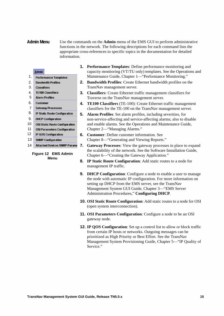
Admin Menu Use the commands on the Admin menu of the EMS GUI to perform administrative functions in the network. The following descriptions for each command lists the appropriate cross-references to specific topics in the documentation for detailed information.
Figure 12 EMS Admin Menu
1. Performance Templates: Define performance monitoring and capacity monitoring (VT/TU only) templates. See the Operations and Maintenance Guide, Chapter 1—“Performance Monitoring.”
2. Bandwidth Profiles: Create Ethernet bandwidth profiles on the TransNav management server.
3. Classifiers: Create Ethernet traffic management classifiers for Traverse on the TransNav management server.
4. TE100 Classifiers (TE-100): Create Ethernet traffic management classifiers for the TE-100 on the TransNav management server.
5. Alarm Profiles: Set alarm profiles, including severities, for non-service-affecting and service-affecting alarms; also to disable and enable alarms. See the Operations and Maintenance Guide, Chapter 2—“Managing Alarms.”
6. Customer: Define customer information. See Chapter 8—“Generating and Viewing Reports.”
7. Gateway Processes: View the gateway processes in place to expand the scalability of the network. See the Software Installation Guide, Chapter 6—“Creating the Gateway Application.”
8. IP Static Route Configuration: Add static routes to a node for management IP traffic.
9. DHCP Configuration: Configure a node to enable a user to manage the node with automatic IP configuration. For more information on setting up DHCP from the EMS server, see the TransNav Management System GUI Guide, Chapter 3—“EMS Server Administration Procedures,” Configuring DHCP.
10. OSI Static Route Configuration: Add static routes to a node for OSI (open system interconnection).
11. OSI Parameters Configuration: Configure a node to be an OSI gateway node.
12. IP QOS Configuration: Set up a control list to allow or block traffic from certain IP hosts or networks. Outgoing messages can be prioritized as High Priority or Best Effort. See the TransNav Management System Provisioning Guide, Chapter 5—“IP Quality of Service.”
1.
2.3.
4.5
8.
9.10
7
6.
1112
13
14
TransNav Management System GUI Guide, Release TN5.0.x 15
13. SNMP Configuration: Set the Traverse node SNMP agent read and write community strings, four trap destination IP addresses, ports, and trap community strings.
14. Attached Devices SNMP Parameters: Set the SNMP sub-shelf devices polling and synchronization intervals for the management server.
16 TransNav Management System GUI Guide, Release TN5.0.x
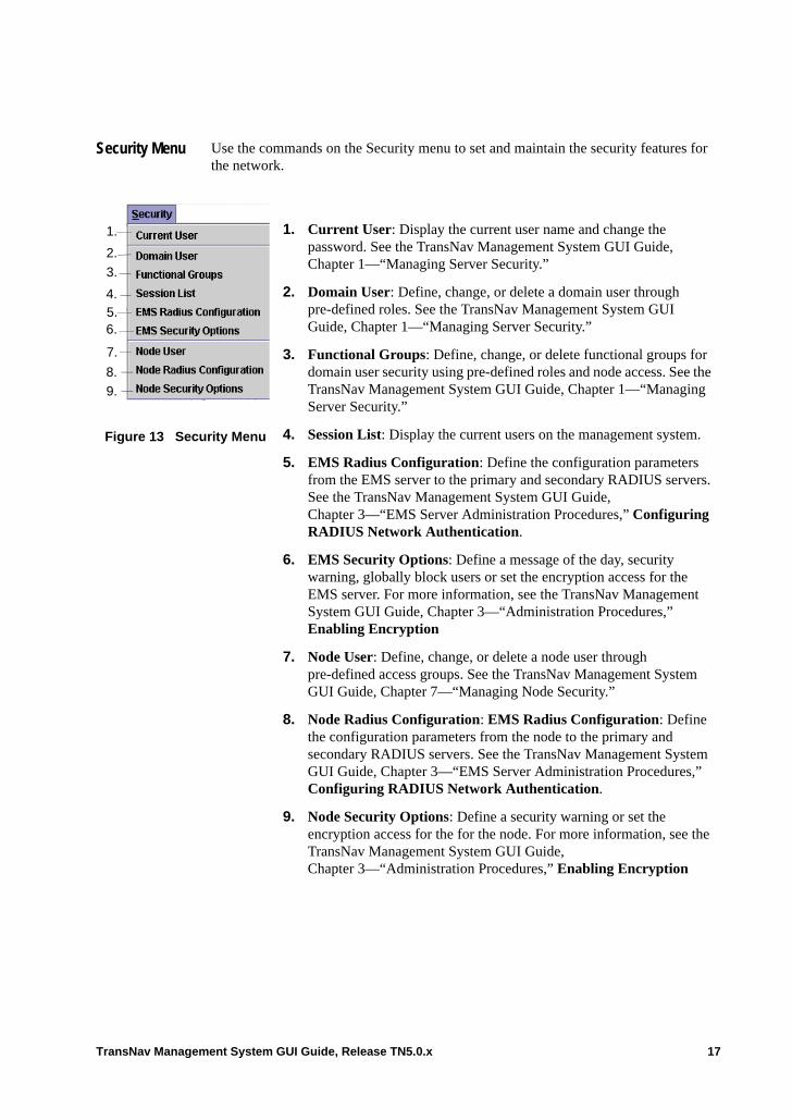
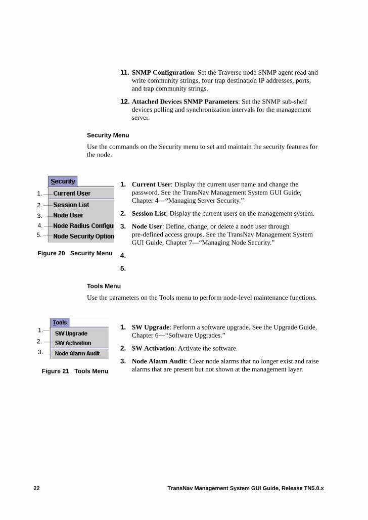
Security Menu Use the commands on the Security menu to set and maintain the security features for the network.
Figure 13 Security Menu
1. Current User: Display the current user name and change the password. See the TransNav Management System GUI Guide, Chapter 1—“Managing Server Security.”
2. Domain User: Define, change, or delete a domain user through pre-defined roles. See the TransNav Management System GUI Guide, Chapter 1—“Managing Server Security.”
3. Functional Groups: Define, change, or delete functional groups for domain user security using pre-defined roles and node access. See the TransNav Management System GUI Guide, Chapter 1—“Managing Server Security.”
4. Session List: Display the current users on the management system.
5. EMS Radius Configuration: Define the configuration parameters from the EMS server to the primary and secondary RADIUS servers. See the TransNav Management System GUI Guide, Chapter 3—“EMS Server Administration Procedures,” Configuring RADIUS Network Authentication.
6. EMS Security Options: Define a message of the day, security warning, globally block users or set the encryption access for the EMS server. For more information, see the TransNav Management System GUI Guide, Chapter 3—“Administration Procedures,” Enabling Encryption
7. Node User: Define, change, or delete a node user through pre-defined access groups. See the TransNav Management System GUI Guide, Chapter 7—“Managing Node Security.”
8. Node Radius Configuration: EMS Radius Configuration: Define the configuration parameters from the node to the primary and secondary RADIUS servers. See the TransNav Management System GUI Guide, Chapter 3—“EMS Server Administration Procedures,” Configuring RADIUS Network Authentication.
9. Node Security Options: Define a security warning or set the encryption access for the for the node. For more information, see the TransNav Management System GUI Guide, Chapter 3—“Administration Procedures,” Enabling Encryption
1.
2.
3.
4.5.6.
7.
8.
9.
TransNav Management System GUI Guide, Release TN5.0.x 17
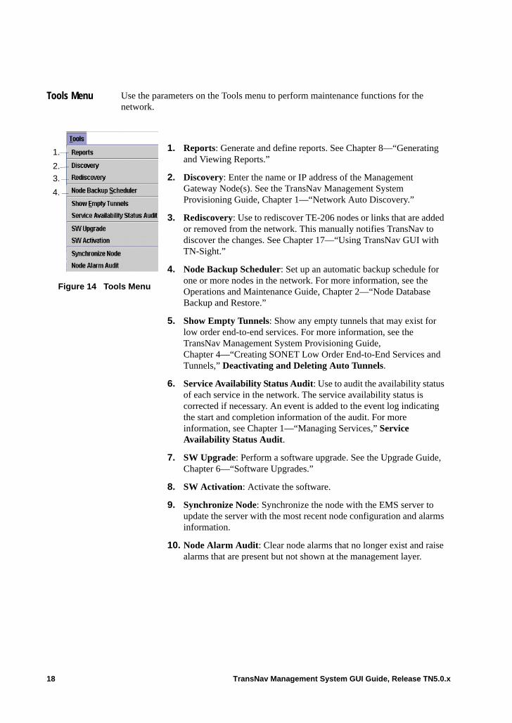
Tools Menu Use the parameters on the Tools menu to perform maintenance functions for the network.
Figure 14 Tools Menu
1. Reports: Generate and define reports. See Chapter 8—“Generating and Viewing Reports.”
2. Discovery: Enter the name or IP address of the Management Gateway Node(s). See the TransNav Management System Provisioning Guide, Chapter 1—“Network Auto Discovery.”
3. Rediscovery: Use to rediscover TE-206 nodes or links that are added or removed from the network. This manually notifies TransNav to discover the changes. See Chapter 17—“Using TransNav GUI with TN-Sight.”
4. Node Backup Scheduler: Set up an automatic backup schedule for one or more nodes in the network. For more information, see the Operations and Maintenance Guide, Chapter 2—“Node Database Backup and Restore.”
5. Show Empty Tunnels: Show any empty tunnels that may exist for low order end-to-end services. For more information, see the TransNav Management System Provisioning Guide, Chapter 4—“Creating SONET Low Order End-to-End Services and Tunnels,” Deactivating and Deleting Auto Tunnels.
6. Service Availability Status Audit: Use to audit the availability status of each service in the network. The service availability status is corrected if necessary. An event is added to the event log indicating the start and completion information of the audit. For more information, see Chapter 1—“Managing Services,” Service Availability Status Audit.
7. SW Upgrade: Perform a software upgrade. See the Upgrade Guide, Chapter 6—“Software Upgrades.”
8. SW Activation: Activate the software.
9. Synchronize Node: Synchronize the node with the EMS server to update the server with the most recent node configuration and alarms information.
10. Node Alarm Audit: Clear node alarms that no longer exist and raise alarms that are present but not shown at the management layer.
1.
2.
3.
4.
18 TransNav Management System GUI Guide, Release TN5.0.x
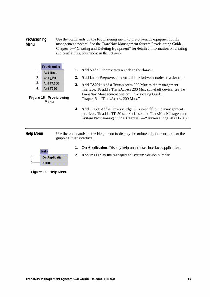
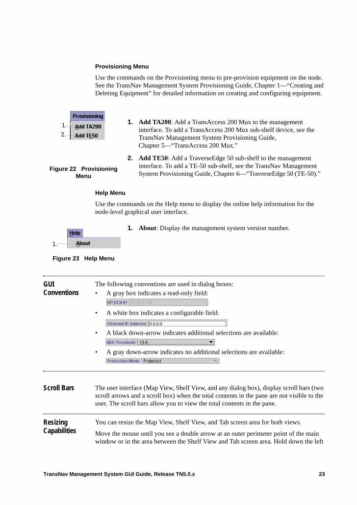
Provisioning Menu
Use the commands on the Provisioning menu to pre-provision equipment in the management system. See the TransNav Management System Provisioning Guide, Chapter 1—“Creating and Deleting Equipment” for detailed information on creating and configuring equipment in the network.
Help Menu Use the commands on the Help menu to display the online help information for the graphical user interface.
Figure 15 Provisioning Menu
1. Add Node: Preprovision a node to the domain.
2. Add Link: Preprovision a virtual link between nodes in a domain.
3. Add TA200: Add a TransAccess 200 Mux to the management interface. To add a TransAccess 200 Mux sub-shelf device, see the TransNav Management System Provisioning Guide, Chapter 5—“TransAccess 200 Mux.”
4. Add TE50: Add a TraverseEdge 50 sub-shelf to the management interface. To add a TE-50 sub-shelf, see the TransNav Management System Provisioning Guide, Chapter 6—“TraverseEdge 50 (TE-50).”
1.
2.
3.
4.
Figure 16 Help Menu
1. On Application: Display help on the user interface application.
2. About: Display the management system version number.1.
2.
TransNav Management System GUI Guide, Release TN5.0.x 19
Node GUI Menus
The Node-level GUI menus are a subsection of the EMS GUI menu, but function in the same ways. The following sections summarize the available Node GUI menu options:• File Menu• View Menu• Admin Menu• Security Menu• Tools Menu• Provisioning Menu
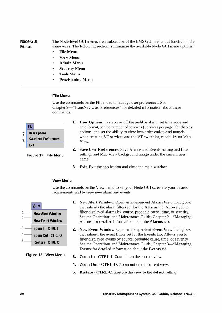
File Menu
Use the commands on the File menu to manage user preferences. See Chapter 9—“TransNav User Preferences” for detailed information about these commands.
View Menu
Use the commands on the View menu to set your Node GUI screen to your desired requirements and to view new alarm and events
Figure 17 File Menu
1. User Options: Turn on or off the audible alarm, set time zone and date format, set the number of services (Services per page) for display options, and set the ability to view low-order end-to-end tunnels when creating VT services and the VT switching capability on Map View.
2. Save User Preferences. Save Alarms and Events sorting and filter settings and Map View background image under the current user name.
3. Exit. Exit the application and close the main window.
1.2.3.
Figure 18 View Menu
1. New Alert Window: Open an independent Alarm View dialog box that inherits the alarm filters set for the Alarms tab. Allows you to filter displayed alarms by source, probable cause, time, or severity. See the Operations and Maintenance Guide, Chapter 2—“Managing Alarms”for detailed information about the Alarms tab.
2. New Event Window: Open an independent Event View dialog box that inherits the event filters set for the Events tab. Allows you to filter displayed events by source, probable cause, time, or severity. See the Operations and Maintenance Guide, Chapter 3—“Managing Events”for detailed information about the Events tab.
3. Zoom In - CTRL-I: Zoom in on the current view.
4. Zoom Out - CTRL-O: Zoom out on the current view.
5. Restore - CTRL-C: Restore the view to the default setting.
1.
2.
3.
4.
5
20 TransNav Management System GUI Guide, Release TN5.0.x
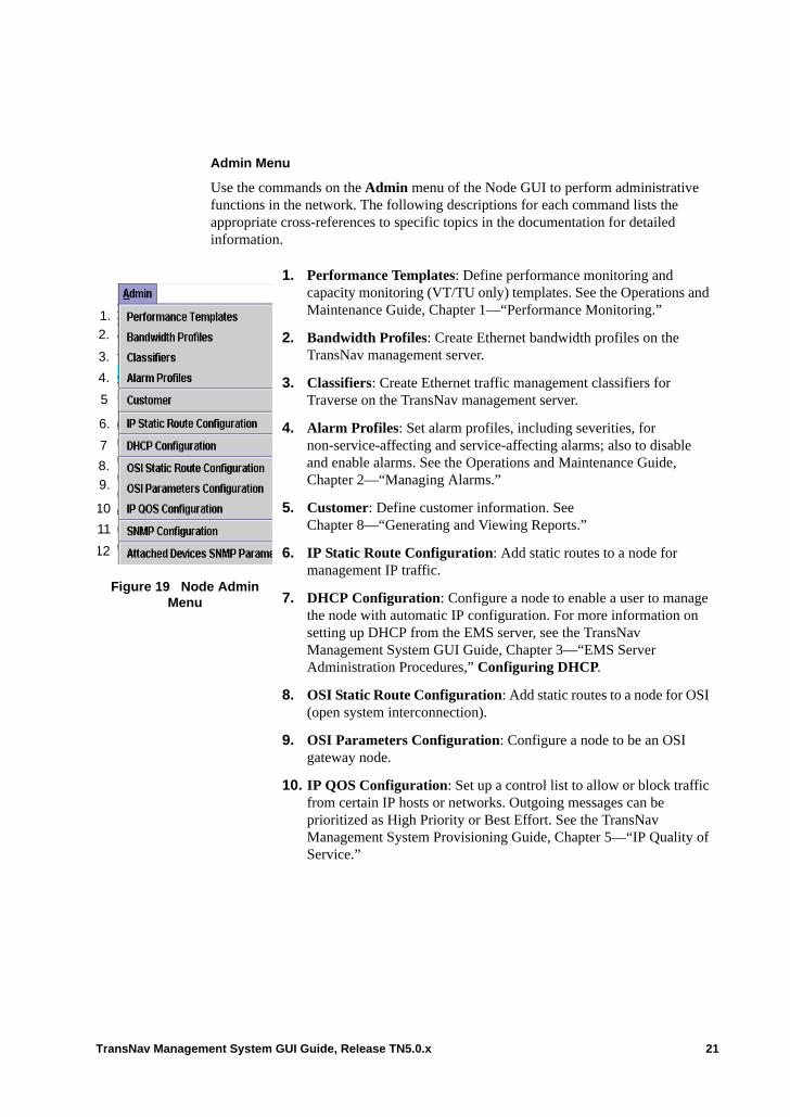
Admin Menu
Use the commands on the Admin menu of the Node GUI to perform administrative functions in the network. The following descriptions for each command lists the appropriate cross-references to specific topics in the documentation for detailed information.
Figure 19 Node Admin Menu
1. Performance Templates: Define performance monitoring and capacity monitoring (VT/TU only) templates. See the Operations and Maintenance Guide, Chapter 1—“Performance Monitoring.”
2. Bandwidth Profiles: Create Ethernet bandwidth profiles on the TransNav management server.
3. Classifiers: Create Ethernet traffic management classifiers for Traverse on the TransNav management server.
4. Alarm Profiles: Set alarm profiles, including severities, for non-service-affecting and service-affecting alarms; also to disable and enable alarms. See the Operations and Maintenance Guide, Chapter 2—“Managing Alarms.”
5. Customer: Define customer information. See Chapter 8—“Generating and Viewing Reports.”
6. IP Static Route Configuration: Add static routes to a node for management IP traffic.
7. DHCP Configuration: Configure a node to enable a user to manage the node with automatic IP configuration. For more information on setting up DHCP from the EMS server, see the TransNav Management System GUI Guide, Chapter 3—“EMS Server Administration Procedures,” Configuring DHCP.
8. OSI Static Route Configuration: Add static routes to a node for OSI (open system interconnection).
9. OSI Parameters Configuration: Configure a node to be an OSI gateway node.
10. IP QOS Configuration: Set up a control list to allow or block traffic from certain IP hosts or networks. Outgoing messages can be prioritized as High Priority or Best Effort. See the TransNav Management System Provisioning Guide, Chapter 5—“IP Quality of Service.”
1.
2.
3.
4.
5
8.
9.
10
7
6.
11
12
TransNav Management System GUI Guide, Release TN5.0.x 21
Security Menu
Use the commands on the Security menu to set and maintain the security features for the node.
Tools Menu
Use the parameters on the Tools menu to perform node-level maintenance functions.
11. SNMP Configuration: Set the Traverse node SNMP agent read and write community strings, four trap destination IP addresses, ports, and trap community strings.
12. Attached Devices SNMP Parameters: Set the SNMP sub-shelf devices polling and synchronization intervals for the management server.
Figure 20 Security Menu
1. Current User: Display the current user name and change the password. See the TransNav Management System GUI Guide, Chapter 4—“Managing Server Security.”
2. Session List: Display the current users on the management system.
3. Node User: Define, change, or delete a node user through pre-defined access groups. See the TransNav Management System GUI Guide, Chapter 7—“Managing Node Security.”
4.
5.
1.
2.
3.
4.
5.
Figure 21 Tools Menu
1. SW Upgrade: Perform a software upgrade. See the Upgrade Guide, Chapter 6—“Software Upgrades.”
2. SW Activation: Activate the software.
3. Node Alarm Audit: Clear node alarms that no longer exist and raise alarms that are present but not shown at the management layer.
1.
2.
3.
22 TransNav Management System GUI Guide, Release TN5.0.x
Provisioning Menu
Use the commands on the Provisioning menu to pre-provision equipment on the node. See the TransNav Management System Provisioning Guide, Chapter 1—“Creating and Deleting Equipment” for detailed information on creating and configuring equipment.
Help Menu
Use the commands on the Help menu to display the online help information for the node-level graphical user interface.
GUI Conventions
The following conventions are used in dialog boxes:• A gray box indicates a read-only field:
• A white box indicates a configurable field:
• A black down-arrow indicates additional selections are available:
• A gray down-arrow indicates no additional selections are available:
Scroll Bars The user interface (Map View, Shelf View, and any dialog box), display scroll bars (two scroll arrows and a scroll box) when the total contents in the pane are not visible to the user. The scroll bars allow you to view the total contents in the pane.
Resizing Capabilities
You can resize the Map View, Shelf View, and Tab screen area for both views.
Move the mouse until you see a double arrow at an outer perimeter point of the main window or in the area between the Shelf View and Tab screen area. Hold down the left
Figure 22 Provisioning Menu
1. Add TA200: Add a TransAccess 200 Mux to the management interface. To add a TransAccess 200 Mux sub-shelf device, see the TransNav Management System Provisioning Guide, Chapter 5—“TransAccess 200 Mux.”
2. Add TE50: Add a TraverseEdge 50 sub-shelf to the management interface. To add a TE-50 sub-shelf, see the TransNav Management System Provisioning Guide, Chapter 6—“TraverseEdge 50 (TE-50).”
1.
2.
Figure 23 Help Menu
1. About: Display the management system version number.
1.
TransNav Management System GUI Guide, Release TN5.0.x 23
mouse button, move the mouse until the window is in the desired position, and release the left mouse button.
24 TransNav Management System GUI Guide, Release TN5.0.x
Chapter 2 Starting the Graphical User Interface
Introduction This chapter contains procedures on how to start the graphical user interface (GUI) for the TransNav management system and the node-level GUI.
EMS GUI
• Starting the GUI from the Management Server• Starting the GUI Application on a Windows Platform• Starting the GUI Application on a Solaris Platform• TransNav Client Workstation GUI User Login
Force10 recommends using the server GUI application directly on the client workstation for faster initialization, operation, and response time. • For Windows workstations, see the Software Installation Guide,
Chapter 3—“Installing the GUI on Windows Workstations.”
For Solaris workstations, see the Software Installation Guide, Chapter 4—“GUI Installation for Solaris Workstations.”
Node-level GUI
The node-level GUI, also called the craft GUI, is used on a client workstation for work at a remote site. Force10 recommends launching between 5 and 10 individual node-level GUIs simultaneously from a single laptop or PC on a Windows platform only; the actual number of GUIs you can start depends on the size of the node and the available RAM.
The node-level GUI is designed to provide faster initialization, operation, and response time for a specific node. DHCP can be configured from the TransNav EMS server or on the node to allow automatic IP configuration for a node user’s Windows computer using the cable jack on the front of the GCM.
Force10 recommends using the Node (craft) GUI application directly on the client workstation for faster initialization, operation, and response time. • Guidelines to Starting the Node-level GUI• Starting the Node-level GUI Application on a Windows Platform• Node-level GUI User Login
TransNav Management System GUI Guide, Release TN5.0.x 1
Starting the GUI from the Management Server
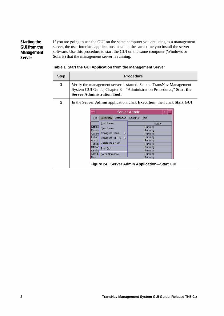
If you are going to use the GUI on the same computer you are using as a management server, the user interface applications install at the same time you install the server software. Use this procedure to start the GUI on the same computer (Windows or Solaris) that the management server is running.
Table 1 Start the GUI Application from the Management Server
Step Procedure
1 Verify the management server is started. See the TransNav Management System GUI Guide, Chapter 3—“Administration Procedures,” Start the Server Administration Tool..
2 In the Server Admin application, click Execution, then click Start GUI.
Figure 24 Server Admin Application—Start GUI
2 TransNav Management System GUI Guide, Release TN5.0.x
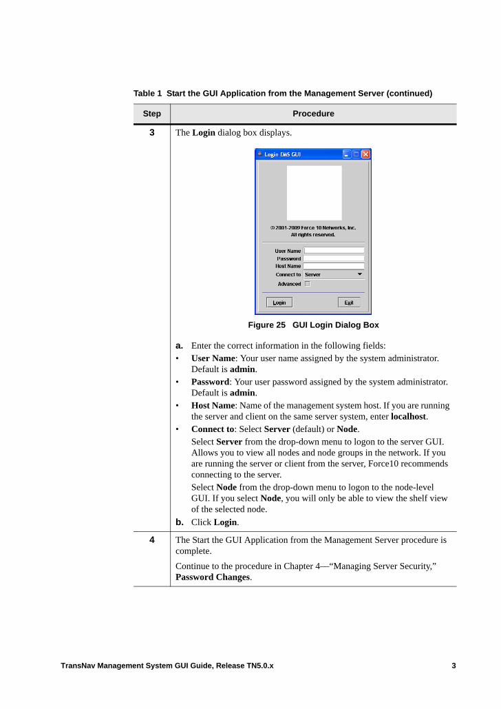
3 The Login dialog box displays.
Figure 25 GUI Login Dialog Box
a. Enter the correct information in the following fields:• User Name: Your user name assigned by the system administrator.
Default is admin.• Password: Your user password assigned by the system administrator.
Default is admin.• Host Name: Name of the management system host. If you are running
the server and client on the same server system, enter localhost.• Connect to: Select Server (default) or Node.
Select Server from the drop-down menu to logon to the server GUI. Allows you to view all nodes and node groups in the network. If you are running the server or client from the server, Force10 recommends connecting to the server. Select Node from the drop-down menu to logon to the node-level GUI. If you select Node, you will only be able to view the shelf view of the selected node.
b. Click Login.
4 The Start the GUI Application from the Management Server procedure is complete.
Continue to the procedure in Chapter 4—“Managing Server Security,” Password Changes.
Table 1 Start the GUI Application from the Management Server (continued)
Step Procedure
TransNav Management System GUI Guide, Release TN5.0.x 3
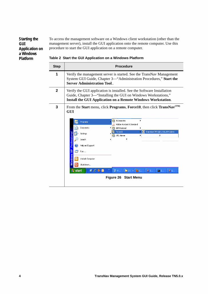
Starting the GUI Application on a Windows Platform
To access the management software on a Windows client workstation (other than the management server), install the GUI application onto the remote computer. Use this procedure to start the GUI application on a remote computer.
Table 2 Start the GUI Application on a Windows Platform
Step Procedure
1 Verify the management server is started. See the TransNav Management System GUI Guide, Chapter 3—“Administration Procedures,” Start the Server Administration Tool..
2 Verify the GUI application is installed. See the Software Installation Guide, Chapter 3—“Installing the GUI on Windows Workstations,” Install the GUI Application on a Remote Windows Workstation.
3 From the Start menu, click Programs, Force10, then click TransNav(TM) GUI
.
.
Figure 26 Start Menu
4 TransNav Management System GUI Guide, Release TN5.0.x
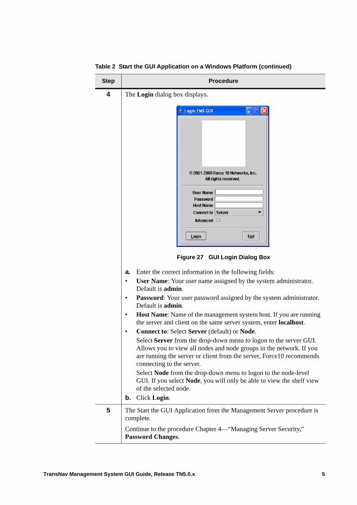
4 The Login dialog box displays.
Figure 27 GUI Login Dialog Box
a. Enter the correct information in the following fields:• User Name: Your user name assigned by the system administrator.
Default is admin.• Password: Your user password assigned by the system administrator.
Default is admin.• Host Name: Name of the management system host. If you are running
the server and client on the same server system, enter localhost.• Connect to: Select Server (default) or Node.
Select Server from the drop-down menu to logon to the server GUI. Allows you to view all nodes and node groups in the network. If you are running the server or client from the server, Force10 recommends connecting to the server. Select Node from the drop-down menu to logon to the node-level GUI. If you select Node, you will only be able to view the shelf view of the selected node.
b. Click Login.
5 The Start the GUI Application from the Management Server procedure is complete.
Continue to the procedure Chapter 4—“Managing Server Security,” Password Changes.
Table 2 Start the GUI Application on a Windows Platform (continued)
Step Procedure
TransNav Management System GUI Guide, Release TN5.0.x 5
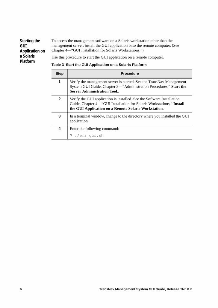
Starting the GUI Application on a Solaris Platform
To access the management software on a Solaris workstation other than the management server, install the GUI application onto the remote computer. (See Chapter 4—“GUI Installation for Solaris Workstations.”)
Use this procedure to start the GUI application on a remote computer.
Table 3 Start the GUI Application on a Solaris Platform
Step Procedure
1 Verify the management server is started. See the TransNav Management System GUI Guide, Chapter 3—“Administration Procedures,” Start the Server Administration Tool..
2 Verify the GUI application is installed. See the Software Installation Guide, Chapter 4—“GUI Installation for Solaris Workstations,” Install the GUI Application on a Remote Solaris Workstation.
3 In a terminal window, change to the directory where you installed the GUI application.
4 Enter the following command:
$ ./ems_gui.sh
6 TransNav Management System GUI Guide, Release TN5.0.x
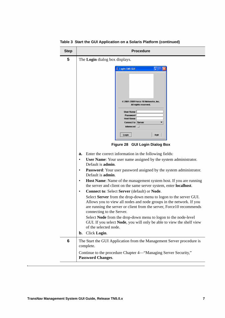
5 The Login dialog box displays.
Figure 28 GUI Login Dialog Box
a. Enter the correct information in the following fields:• User Name: Your user name assigned by the system administrator.
Default is admin.• Password: Your user password assigned by the system administrator.
Default is admin.• Host Name: Name of the management system host. If you are running
the server and client on the same server system, enter localhost.• Connect to: Select Server (default) or Node.
Select Server from the drop-down menu to logon to the server GUI. Allows you to view all nodes and node groups in the network. If you are running the server or client from the server, Force10 recommends connecting to the Server. Select Node from the drop-down menu to logon to the node-level GUI. If you select Node, you will only be able to view the shelf view of the selected node.
b. Click Login.
6 The Start the GUI Application from the Management Server procedure is complete.
Continue to the procedure Chapter 4—“Managing Server Security,” Password Changes.
Table 3 Start the GUI Application on a Solaris Platform (continued)
Step Procedure
TransNav Management System GUI Guide, Release TN5.0.x 7
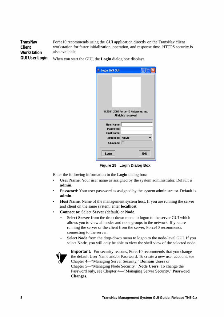
TransNav Client Workstation GUI User Login
Force10 recommends using the GUI application directly on the TransNav client workstation for faster initialization, operation, and response time. HTTPS security is also available.
When you start the GUI, the Login dialog box displays.
Figure 29 Login Dialog Box
Enter the following information in the Login dialog box:• User Name: Your user name as assigned by the system administrator. Default is
admin.• Password: Your user password as assigned by the system administrator. Default is
admin.• Host Name: Name of the management system host. If you are running the server
and client on the same system, enter localhost• Connect to: Select Server (default) or Node.
– Select Server from the drop-down menu to logon to the server GUI which allows you to view all nodes and node groups in the network. If you are running the server or the client from the server, Force10 recommends connecting to the server.
– Select Node from the drop-down menu to logon to the node-level GUI. If you select Node, you will only be able to view the shelf view of the selected node.
Important: For security reasons, Force10 recommends that you change the default User Name and/or Password. To create a new user account, see Chapter 4—“Managing Server Security,” Domain Users or Chapter 5—“Managing Node Security,” Node Users. To change the Password only, see Chapter 4—“Managing Server Security,” Password Changes.
8 TransNav Management System GUI Guide, Release TN5.0.x
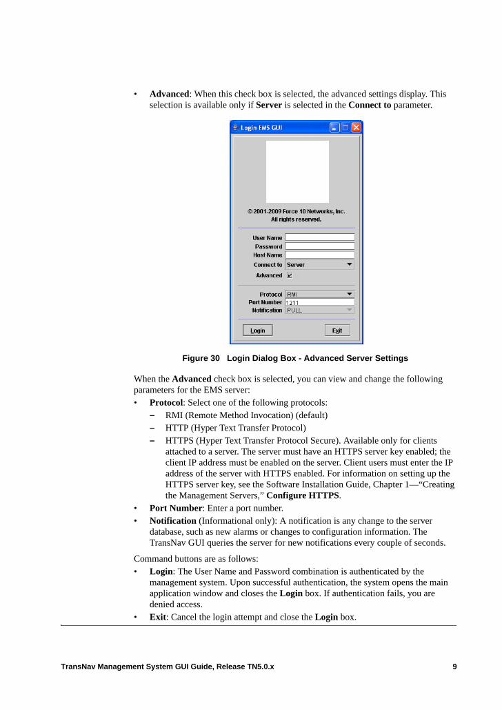
• Advanced: When this check box is selected, the advanced settings display. This selection is available only if Server is selected in the Connect to parameter.
Figure 30 Login Dialog Box - Advanced Server Settings
When the Advanced check box is selected, you can view and change the following parameters for the EMS server:• Protocol: Select one of the following protocols:
– RMI (Remote Method Invocation) (default)– HTTP (Hyper Text Transfer Protocol)– HTTPS (Hyper Text Transfer Protocol Secure). Available only for clients
attached to a server. The server must have an HTTPS server key enabled; the client IP address must be enabled on the server. Client users must enter the IP address of the server with HTTPS enabled. For information on setting up the HTTPS server key, see the Software Installation Guide, Chapter 1—“Creating the Management Servers,” Configure HTTPS.
• Port Number: Enter a port number.• Notification (Informational only): A notification is any change to the server
database, such as new alarms or changes to configuration information. The TransNav GUI queries the server for new notifications every couple of seconds.
Command buttons are as follows:• Login: The User Name and Password combination is authenticated by the
management system. Upon successful authentication, the system opens the main application window and closes the Login box. If authentication fails, you are denied access.
• Exit: Cancel the login attempt and close the Login box.
TransNav Management System GUI Guide, Release TN5.0.x 9
Guidelines to Starting the Node-level GUI
Use the following guidelines to set up and start the node-level GUI.
Download a copy of the management system server software to a directory accessible by all users to download the node-level GUI. The server software can have a blank database.• Verify the node and server are using the same software version. • For new installations, make sure the web browser settings for Internet Explorer
have been set up. For more information, see the Software Installation Guide, Chapter 3—“Installing the GUI on Windows Workstations,” Install the GUI Application on a Remote Windows Workstation.
• To access the node-level GUI from a remote computer using a jack on a GCM card, you must configure the DHCP on either the management server GUI or on the node-level GUI from the Admin menu.
• If DHCP is not configured, assign an IP address to the laptop. The GCM Gateway must have the same IP address as the GCM IP. The debug-gw IP address must also match the GCM IP address.
Install the Node-level GUI
A copy of the management system server software must be downloaded to a directory accessible by all users to download the node-level GUI. The server software can have a blank database. When the server software is downloaded, remote users can install the node-level GUI application to their laptop by opening a web browser window and entering http://<server name>:9090 in the locator bar.
For instructions on installing the GUI application, see the Software Installation Guide, Chapter 3—“Installing the GUI on Windows Workstations,” Install the GUI Application on a Remote Windows Workstation.
10 TransNav Management System GUI Guide, Release TN5.0.x
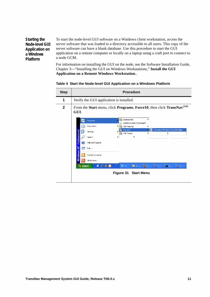
Starting the Node-level GUI Application on a Windows Platform
To start the node-level GUI software on a Windows client workstation, access the server software that was loaded to a directory accessible to all users. This copy of the server software can have a blank database. Use this procedure to start the GUI application on a remote computer or locally on a laptop using a craft port to connect to a node GCM.
For information on installing the GUI on the node, see the Software Installation Guide, Chapter 3—“Installing the GUI on Windows Workstations,” Install the GUI Application on a Remote Windows Workstation..
Table 4 Start the Node-level GUI Application on a Windows Platform
Step Procedure
1 Verify the GUI application is installed.
2 From the Start menu, click Programs, Force10, then click TransNav(TM) GUI.
Figure 31 Start Menu
TransNav Management System GUI Guide, Release TN5.0.x 11
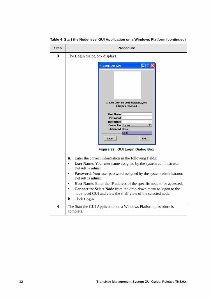
3 The Login dialog box displays.
Figure 32 GUI Login Dialog Box
a. Enter the correct information in the following fields:• User Name: Your user name assigned by the system administrator.
Default is admin.• Password: Your user password assigned by the system administrator.
Default is admin.• Host Name: Enter the IP address of the specific node to be accessed.• Connect to: Select Node from the drop-down menu to logon to the
node-level GUI and view the shelf view of the selected node.
b. Click Login.
4 The Start the GUI Application on a Windows Platform procedure is complete.
Table 4 Start the Node-level GUI Application on a Windows Platform (continued)
Step Procedure
12 TransNav Management System GUI Guide, Release TN5.0.x
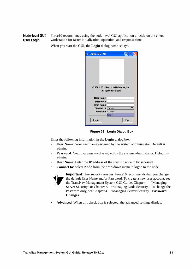
Node-level GUI User Login
Force10 recommends using the node-level GUI application directly on the client workstation for faster initialization, operation, and response time.
When you start the GUI, the Login dialog box displays.
Figure 33 Login Dialog Box
Enter the following information in the Login dialog box:• User Name: Your user name assigned by the system administrator. Default is
admin.• Password: Your user password assigned by the system administrator. Default is
admin.• Host Name: Enter the IP address of the specific node to be accessed. • Connect to: Select Node from the drop-down menu to logon to the node.
• Advanced: When this check box is selected, the advanced settings display.
Important: For security reasons, Force10 recommends that you change the default User Name and/or Password. To create a new user account, see the TransNav Management System GUI Guide, Chapter 4—“Managing Server Security” or Chapter 5—“Managing Node Security.” To change the Password only, see Chapter 4—“Managing Server Security,” Password Changes.
TransNav Management System GUI Guide, Release TN5.0.x 13
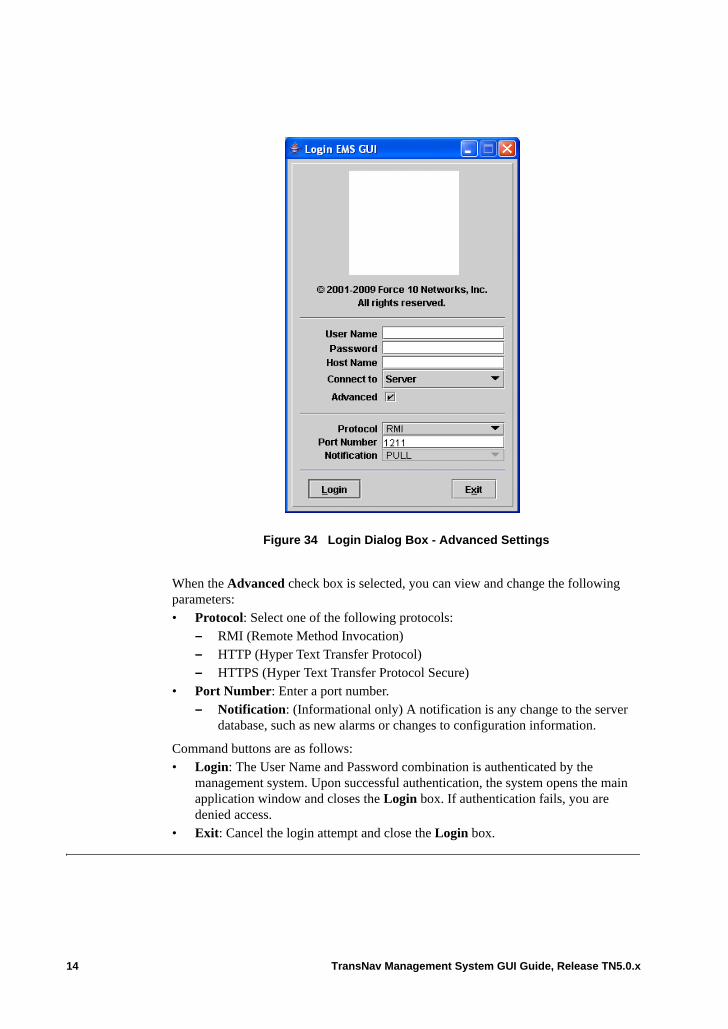
Figure 34 Login Dialog Box - Advanced Settings
When the Advanced check box is selected, you can view and change the following parameters:• Protocol: Select one of the following protocols:
– RMI (Remote Method Invocation)– HTTP (Hyper Text Transfer Protocol)– HTTPS (Hyper Text Transfer Protocol Secure)
• Port Number: Enter a port number.– Notification: (Informational only) A notification is any change to the server
database, such as new alarms or changes to configuration information.
Command buttons are as follows:• Login: The User Name and Password combination is authenticated by the
management system. Upon successful authentication, the system opens the main application window and closes the Login box. If authentication fails, you are denied access.
• Exit: Cancel the login attempt and close the Login box.
14 TransNav Management System GUI Guide, Release TN5.0.x
Chapter 3 Administration Procedures
Introduction This chapter contains procedures for administration of the management system from both the TransNav GUI and the Node GUI.
The TransNav and TN-Xpert management system applications can co-exist in a SONET only environment and be run independently on a single workstation. For more information, see the Software Installation Guide, Chapter 1—“Creating the Management Servers.”
For information on creating Gateway servers to expand your network, see the Software Installation Guide, Chapter 7—“Creating the Gateway Application.”
Server administration functions include the following procedures: • Start the Server Administration Tool• Initialize the Database• Enable the Server as a Service (Windows)• Start the Server• Export (Backup) the Database• Stop the Server• Promoting a Secondary Server to the Primary Role• Disable Server as a Service (Windows)• Disable DEP Service on Server (Windows)• Upgrade Server Software• Download the Management Software from the Force10 Website• Import the Database• Configuring RADIUS Network Authentication• Retrieve Server Log Files• Setting Up Report Parameters• Customizing Background Images for Map View• Configuring DHCP• Setting a Broadcast Message• Terminating User Sessions in Bulk• Setting Administrative Options
– Setting a Security Warning
TransNav Management System GUI Guide, Release TN5.0.x 1
– Setting a Message of the Day– Setting Up the Global User Block– Enabling Encryption
• Restore Default Server Parameters
Start the Server Administration Tool
Start the Server Administration Tool on the management server or gateway server where the server software is installed. For instructions to open the Server Administration Tool, see the Software Installation Guide, Chapter 1—“Creating the Management Servers,” Start the Server Administration Tool.
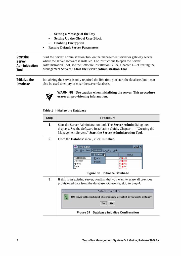
Initialize the Database
Initializing the server is only required the first time you start the database, but it can also be used to empty or clear the server database.
WARNING! Use caution when initializing the server. This procedure erases all provisioning information.
Table 1 Initialize the Database
Step Procedure
1 Start the Server Administration tool. The Server Admin dialog box displays. See the Software Installation Guide, Chapter 1—“Creating the Management Servers,” Start the Server Administration Tool.
2 From the Database menu, click Initialize.
Figure 36 Initialize Database
3 If this is an existing server, confirm that you want to erase all previous provisioned data from the database. Otherwise, skip to Step 4.
Figure 37 Database Initialize Confirmation
2 TransNav Management System GUI Guide, Release TN5.0.x
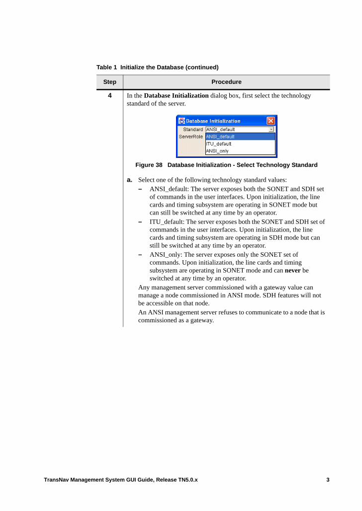
4 In the Database Initialization dialog box, first select the technology standard of the server.
Figure 38 Database Initialization - Select Technology Standard
a. Select one of the following technology standard values: – ANSI_default: The server exposes both the SONET and SDH set
of commands in the user interfaces. Upon initialization, the line cards and timing subsystem are operating in SONET mode but can still be switched at any time by an operator.
– ITU_default: The server exposes both the SONET and SDH set of commands in the user interfaces. Upon initialization, the line cards and timing subsystem are operating in SDH mode but can still be switched at any time by an operator.
– ANSI_only: The server exposes only the SONET set of commands. Upon initialization, the line cards and timing subsystem are operating in SONET mode and can never be switched at any time by an operator.
Any management server commissioned with a gateway value can manage a node commissioned in ANSI mode. SDH features will not be accessible on that node. An ANSI management server refuses to communicate to a node that is commissioned as a gateway.
Table 1 Initialize the Database (continued)
Step Procedure
TransNav Management System GUI Guide, Release TN5.0.x 3
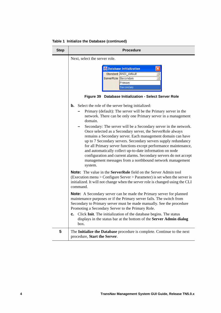
Next, select the server role.
Figure 39 Database Initialization - Select Server Role
b. Select the role of the server being initialized:– Primary (default): The server will be the Primary server in the
network. There can be only one Primary server in a management domain.
– Secondary: The server will be a Secondary server in the network. Once selected as a Secondary server, the ServerRole always remains a Secondary server. Each management domain can have up to 7 Secondary servers. Secondary servers supply redundancy for all Primary server functions except performance maintenance, and automatically collect up-to-date information on node configuration and current alarms. Secondary servers do not accept management messages from a northbound network management system.
Note: The value in the ServerRole field on the Server Admin tool (Execution menu > Configure Server > Parameter) is set when the server is initialized. It will not change when the server role is changed using the CLI command.
Note: A Secondary server can be made the Primary server for planned maintenance purposes or if the Primary server fails. The switch from Secondary to Primary server must be made manually. See the procedure Promoting a Secondary Server to the Primary Role.
c. Click Init. The initialization of the database begins. The status displays in the status bar at the bottom of the Server Admin dialog box.
5 The Initialize the Database procedure is complete. Continue to the next procedure, Start the Server.
Table 1 Initialize the Database (continued)
Step Procedure
4 TransNav Management System GUI Guide, Release TN5.0.x
Enable the Server as a Service (Windows)
If this is a Windows workstation, use this procedure to allow the server to restart on the workstation in case the workstation turns off or power cycles. This procedure restarts the server when the workstation starts again.
Start the Server
To start the management server, select Start Server from the Execution menu. The progress is shown in the status bar.
Table 2 Enable the Server as a Service
Step Procedure
1 The server must be stopped. To stop the server, see the procedure Stop the Server.
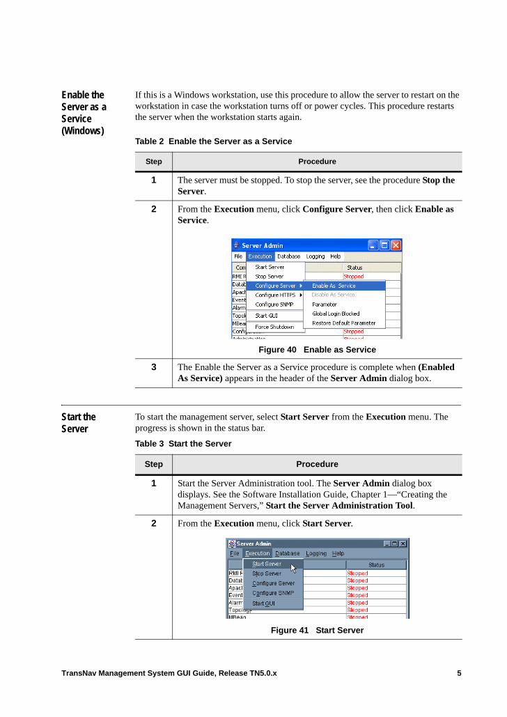
2 From the Execution menu, click Configure Server, then click Enable as Service.
Figure 40 Enable as Service
3 The Enable the Server as a Service procedure is complete when (Enabled As Service) appears in the header of the Server Admin dialog box.
Table 3 Start the Server
Step Procedure
1 Start the Server Administration tool. The Server Admin dialog box displays. See the Software Installation Guide, Chapter 1—“Creating the Management Servers,” Start the Server Administration Tool.
2 From the Execution menu, click Start Server.
Figure 41 Start Server
TransNav Management System GUI Guide, Release TN5.0.x 5
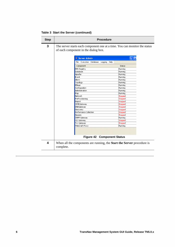
3 The server starts each component one at a time. You can monitor the status of each component in the dialog box.
Figure 42 Component Status
4 When all the components are running, the Start the Server procedure is complete.
Table 3 Start the Server (continued)
Step Procedure
6 TransNav Management System GUI Guide, Release TN5.0.x
Export (Backup) the Database
Export copies of provisioning data stored on a node. If you need to restore the exported copy at a later date, you can retrieve the data using the Import function (explained in the procedure, Import the Database) on the Server Administration tool. The database can be exported manually or scheduled for automatic backup as defined in the following procedures.
Manually Export the Database
Table 4 Manually Export the Database
Step Procedure
1 Before exporting the database, you may want to create a specific directory in which to store the exported database.
2 Start the Server Administration tool. The Server Admin dialog box displays. See the Software Installation Guide, Chapter 1—“Creating the Management Servers,” Start the Server Administration Tool.
TransNav Management System GUI Guide, Release TN5.0.x 7
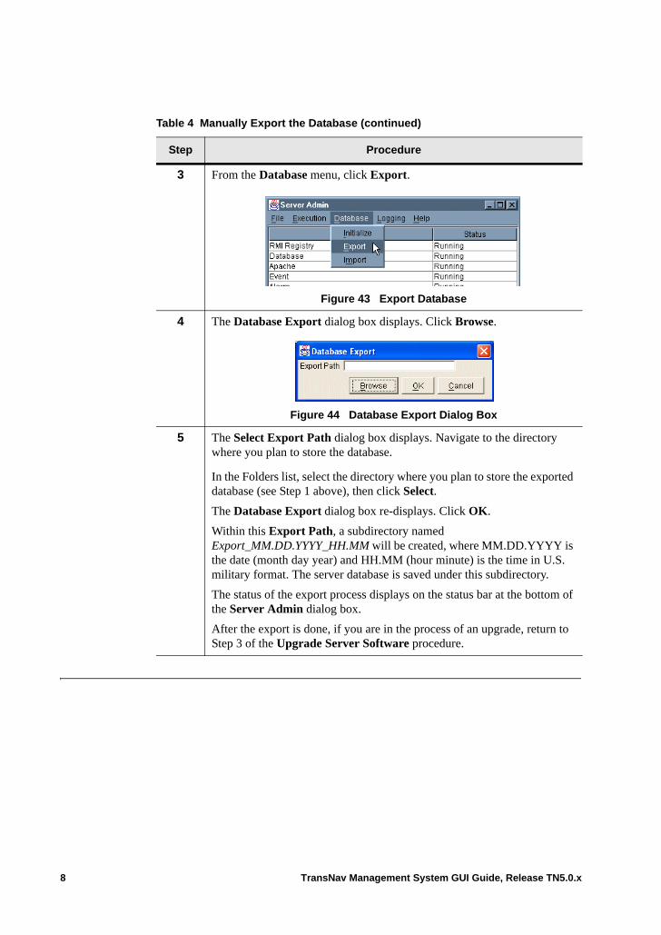
3 From the Database menu, click Export.
Figure 43 Export Database
4 The Database Export dialog box displays. Click Browse.
Figure 44 Database Export Dialog Box
5 The Select Export Path dialog box displays. Navigate to the directory where you plan to store the database.
In the Folders list, select the directory where you plan to store the exported database (see Step 1 above), then click Select.
The Database Export dialog box re-displays. Click OK.
Within this Export Path, a subdirectory named Export_MM.DD.YYYY_HH.MM will be created, where MM.DD.YYYY is the date (month day year) and HH.MM (hour minute) is the time in U.S. military format. The server database is saved under this subdirectory.
The status of the export process displays on the status bar at the bottom of the Server Admin dialog box.
After the export is done, if you are in the process of an upgrade, return to Step 3 of the Upgrade Server Software procedure.
Table 4 Manually Export the Database (continued)
Step Procedure
8 TransNav Management System GUI Guide, Release TN5.0.x
Scheduling the Server Database Backup
Table 5 Scheduling the Server Database Backup
Step Procedure
1 Before exporting the database, you may want to create a specific directory in which to store the exported database.
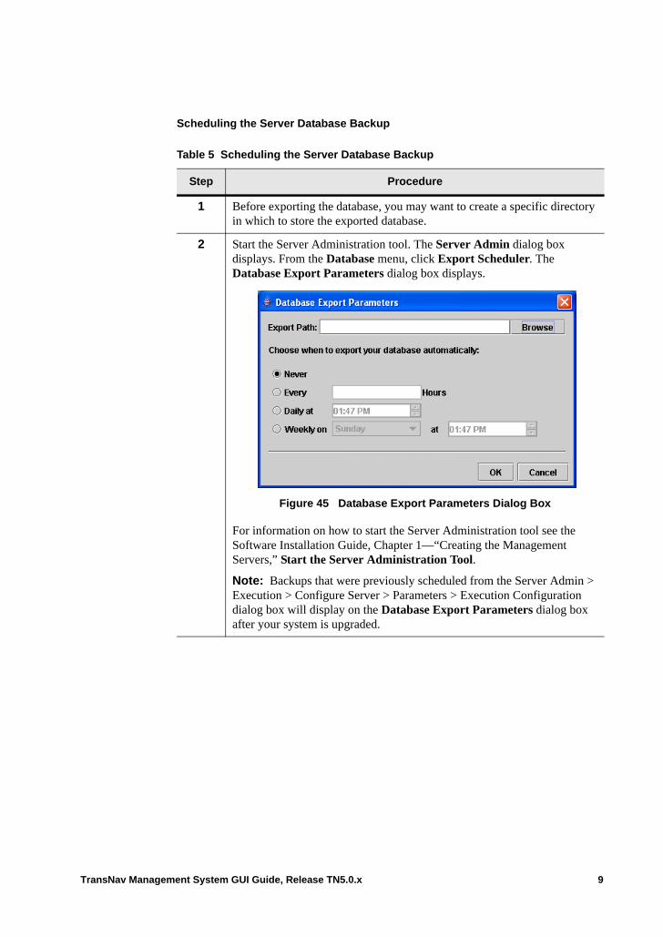
2 Start the Server Administration tool. The Server Admin dialog box displays. From the Database menu, click Export Scheduler. The Database Export Parameters dialog box displays.
Figure 45 Database Export Parameters Dialog Box
For information on how to start the Server Administration tool see the Software Installation Guide, Chapter 1—“Creating the Management Servers,” Start the Server Administration Tool.
Note: Backups that were previously scheduled from the Server Admin > Execution > Configure Server > Parameters > Execution Configuration dialog box will display on the Database Export Parameters dialog box after your system is upgraded.
TransNav Management System GUI Guide, Release TN5.0.x 9
3 Set the following parameters to schedule when to backup the server database.
Export Path: Use the Browse button to navigate to the directory where you plan to store the database. This field is required.
Never (default): The server database files will never be backed up automatically.
Every (x) hours: Enter the number of hours you want the server database to be backed up. Valid values are 1 to 1000.
Daily at: Enter the time you want a daily backup of the database to occur.
Weekly on: Enter the day of the week and the time of day that you want the server database to be backed up.
Click OK to accept the changes or click Cancel.
Important: You must restart the server to have these parameter changes take effect.
The Scheduling the Server Database Backup procedure is complete.
4 If you are in the process of an upgrade, return to Step 3 of the Upgrade Server Software procedure.
Table 5 Scheduling the Server Database Backup (continued)
Step Procedure
10 TransNav Management System GUI Guide, Release TN5.0.x
Stop the Server
To shut down the management server, select Stop Server from the Execution menu. The progress is shown in the status bar.
WARNING! The procedure below stops all server processes, as well as stopping the database.
Table 6 Stop the Server
Step Procedure
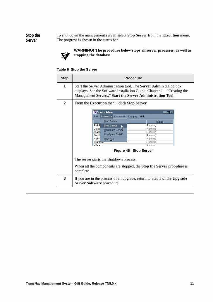
1 Start the Server Administration tool. The Server Admin dialog box displays. See the Software Installation Guide, Chapter 1—“Creating the Management Servers,” Start the Server Administration Tool.
2 From the Execution menu, click Stop Server.
Figure 46 Stop Server
The server starts the shutdown process.
When all the components are stopped, the Stop the Server procedure is complete.
3 If you are in the process of an upgrade, return to Step 5 of the Upgrade Server Software procedure.
TransNav Management System GUI Guide, Release TN5.0.x 11
Promoting a Secondary Server to the Primary Role
Each TransNav management system supports up to 8 servers in the same domain; one Primary server and up to 7 Secondary servers. Use the following procedure to promote a Secondary server to the Primary server role.
Important: Promoting a Secondary server requires that steps are done in the following order: export the Primary server database, stop the Secondary server to be promoted, import the saved database onto the Secondary server, restart the Secondary server, switch the Secondary server’s role to the Primary server role, and finally, either stop the original (previous) Primary server or switch it to a Secondary server role.
Table 7 Promoting a Secondary Server to the Primary Role
Step Procedure
1 Force10 recommends creating a backup of the database on the current Primary server. See the procedure Manually Export the Database. The backup captures recent server or domain-level changes to import to the database of the Secondary server being promoted.
2 Login to the Secondary server that is to be promoted to the role of Primary server and stop the server. See the procedure Stop the Server.
3 Import the copy of the backed up database from the original Primary server onto the Secondary server. Depending on the network size, this can take 1 to 5 minutes. See the procedure Import the Database.
Important: If you skip this step, recent server or domain-level changes made on the original Primary server will not be in effect on the new Primary server when the role is switched.
4 Restart the Secondary server from the Server Administration tool. See the procedure Start the Server.
12 TransNav Management System GUI Guide, Release TN5.0.x
5 Switch the Secondary server to the Primary server role using the following steps:
a. Login to the Secondary server.
b. From the server CLI, enter exec ems switch role Primary
Note: The value in the ServerRole field on the Server Admin tool (Execution > Configure Server > Parameter) is set when the server is initialized. It will not change when the server role is changed using the CLI command.
Until the original Primary server is demoted to a Secondary server role, two Primary servers will exist in the Traverse system. This ensures no alarms or events are lost.
Each Traverse node will raise alarms when two Primary servers are detected. The alarms clear when the original Primary server is stopped or demoted to a Secondary server role.
Note: If more than one Primary server exists in the Traverse system, some situations could occur involving node failure and recovery resulting in inconsistent node configuration. Force10 recommends changing the role of the original Primary server as soon as possible.
6 Stop the original Primary server or switch the role to Secondary server. To stop the server, see the procedure Start the Server. To switch the original Primary server to a Secondary server role, use the following steps:
a. Login to the original Primary server.
b. From the server CLI, enter exec ems switch role Secondary
7 The Promoting a Secondary Server to the Primary Role procedure is complete.
Table 7 Promoting a Secondary Server to the Primary Role (continued)
Step Procedure
TransNav Management System GUI Guide, Release TN5.0.x 13
Disable Server as a Service (Windows)
If this is a Windows workstation, use this procedure to disable the server as a service. The services must be disabled before you upgrade the server software.
Table 8 Disable Server as a Service
Step Procedure
1 Start the Server Administration tool to disable the server as a service. The Server Admin dialog box displays. See the Software Installation Guide, Chapter 1—“Creating the Management Servers,” Start the Server Administration Tool.
2 Stop the server. See the procedure Stop the Server.
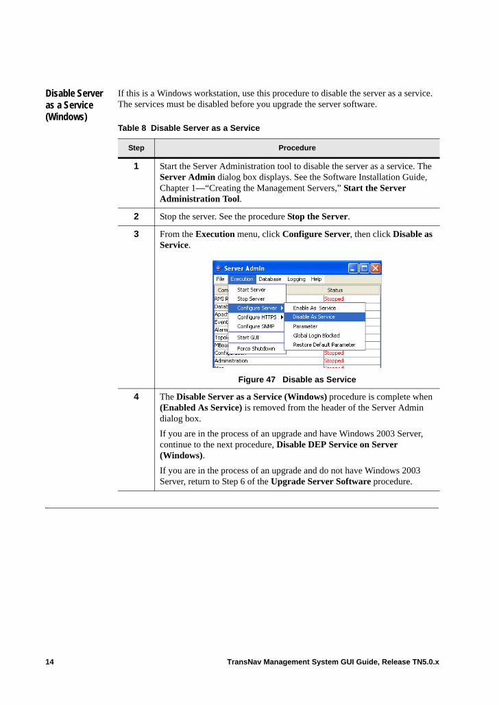
3 From the Execution menu, click Configure Server, then click Disable as Service.
Figure 47 Disable as Service
4 The Disable Server as a Service (Windows) procedure is complete when (Enabled As Service) is removed from the header of the Server Admin dialog box.
If you are in the process of an upgrade and have Windows 2003 Server, continue to the next procedure, Disable DEP Service on Server (Windows).
If you are in the process of an upgrade and do not have Windows 2003 Server, return to Step 6 of the Upgrade Server Software procedure.
14 TransNav Management System GUI Guide, Release TN5.0.x
Disable DEP Service on Server (Windows)
If your server is running Windows 2003 Server, you may need to modify the DEP (Data Execution Prevention) settings to allow the Force10 system to function properly. You must be logged in as Administrator to disable the DEP service.
Table 9 Disable DEP Service on Server
Step Procedure
1 Right-click My Computer using the desktop icon or from Windows Explorer. Select Properties from the shortcut menu. The Systems Properties dialog box displays.
2 Click the Advanced tab.
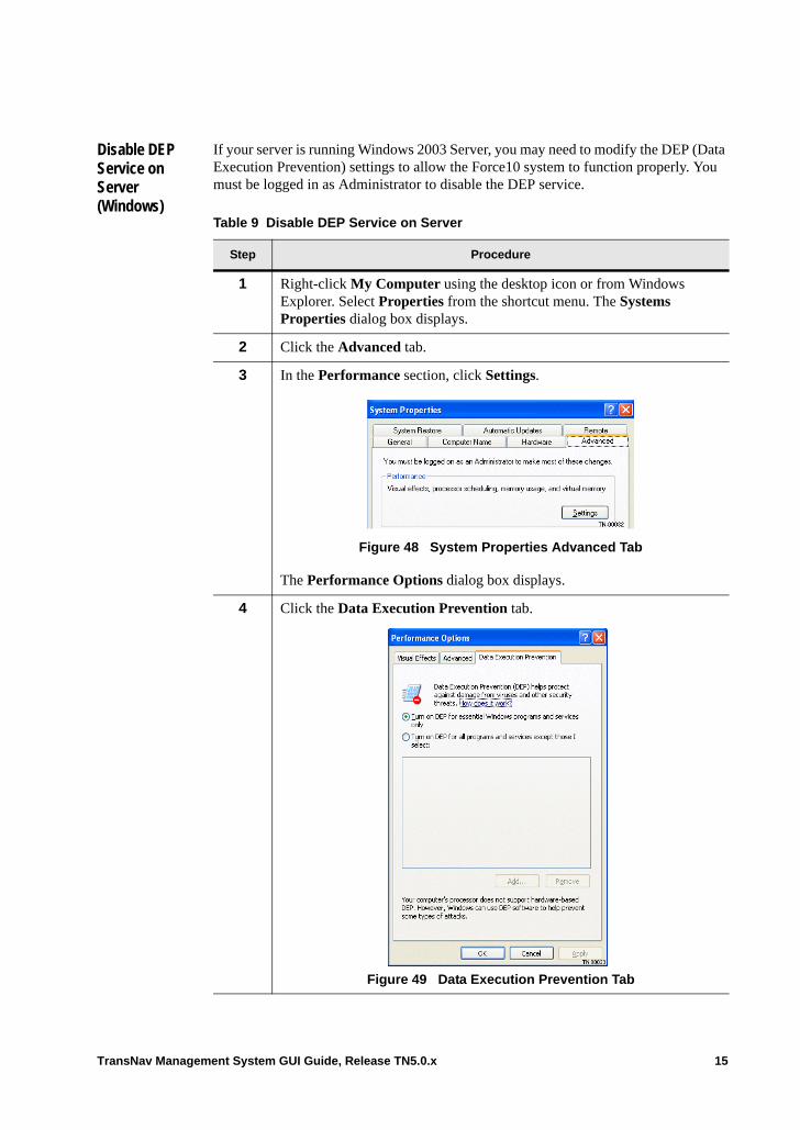
3 In the Performance section, click Settings.
Figure 48 System Properties Advanced Tab
The Performance Options dialog box displays.
4 Click the Data Execution Prevention tab.
Figure 49 Data Execution Prevention Tab
TransNav Management System GUI Guide, Release TN5.0.x 15
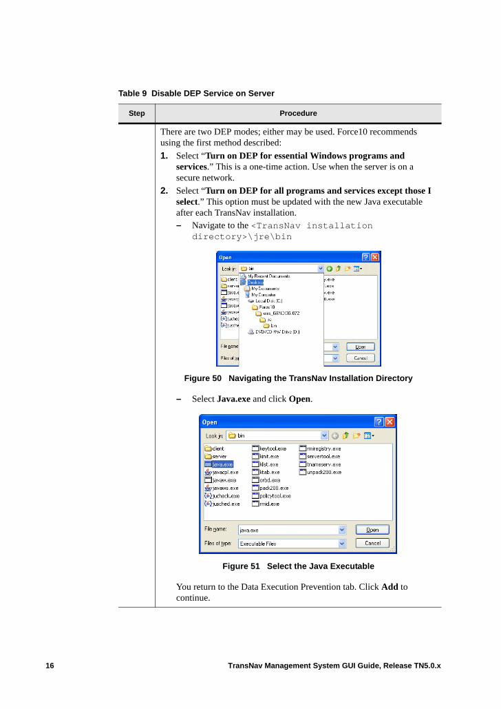
There are two DEP modes; either may be used. Force10 recommends using the first method described:
1. Select “Turn on DEP for essential Windows programs and services.” This is a one-time action. Use when the server is on a secure network.
2. Select “Turn on DEP for all programs and services except those I select.” This option must be updated with the new Java executable after each TransNav installation.– Navigate to the <TransNav installation
directory>\jre\bin
Figure 50 Navigating the TransNav Installation Directory
– Select Java.exe and click Open.
Figure 51 Select the Java Executable
You return to the Data Execution Prevention tab. Click Add to continue.
Table 9 Disable DEP Service on Server
Step Procedure
16 TransNav Management System GUI Guide, Release TN5.0.x
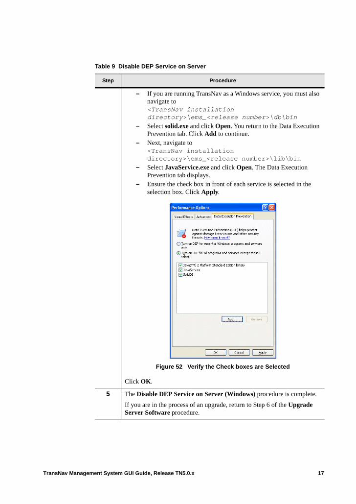
– If you are running TransNav as a Windows service, you must also navigate to<TransNav installation directory>\ems_<release number>\db\bin
– Select solid.exe and click Open. You return to the Data Execution Prevention tab. Click Add to continue.
– Next, navigate to <TransNav installation directory>\ems_<release number>\lib\bin
– Select JavaService.exe and click Open. The Data Execution Prevention tab displays.
– Ensure the check box in front of each service is selected in the selection box. Click Apply.
Figure 52 Verify the Check boxes are Selected
Click OK.
5 The Disable DEP Service on Server (Windows) procedure is complete.
If you are in the process of an upgrade, return to Step 6 of the Upgrade Server Software procedure.
Table 9 Disable DEP Service on Server
Step Procedure
TransNav Management System GUI Guide, Release TN5.0.x 17
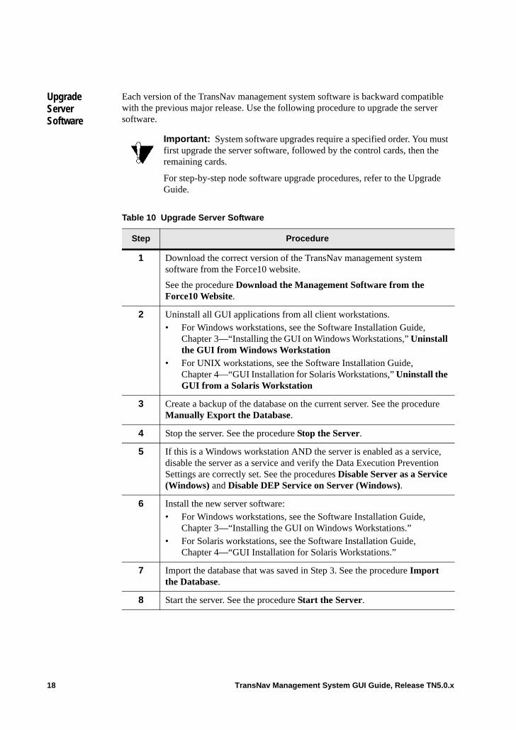
Upgrade Server Software
Each version of the TransNav management system software is backward compatible with the previous major release. Use the following procedure to upgrade the server software.
Important: System software upgrades require a specified order. You must first upgrade the server software, followed by the control cards, then the remaining cards.
For step-by-step node software upgrade procedures, refer to the Upgrade Guide.
Table 10 Upgrade Server Software
Step Procedure
1 Download the correct version of the TransNav management system software from the Force10 website.
See the procedure Download the Management Software from the Force10 Website.
2 Uninstall all GUI applications from all client workstations. • For Windows workstations, see the Software Installation Guide,
Chapter 3—“Installing the GUI on Windows Workstations,” Uninstall the GUI from Windows Workstation
• For UNIX workstations, see the Software Installation Guide, Chapter 4—“GUI Installation for Solaris Workstations,” Uninstall the GUI from a Solaris Workstation
3 Create a backup of the database on the current server. See the procedure Manually Export the Database.
4 Stop the server. See the procedure Stop the Server.
5 If this is a Windows workstation AND the server is enabled as a service, disable the server as a service and verify the Data Execution Prevention Settings are correctly set. See the procedures Disable Server as a Service (Windows) and Disable DEP Service on Server (Windows).
6 Install the new server software: • For Windows workstations, see the Software Installation Guide,
Chapter 3—“Installing the GUI on Windows Workstations.”• For Solaris workstations, see the Software Installation Guide,
Chapter 4—“GUI Installation for Solaris Workstations.”
7 Import the database that was saved in Step 3. See the procedure Import the Database.
8 Start the server. See the procedure Start the Server.
18 TransNav Management System GUI Guide, Release TN5.0.x
Download the Management Software from the Force10 Website
Use this procedure to download the latest management server software from the Force10 website.
Note: A Customer Portal Account is required. If you do not have a Customer Portal Account, you can request one from the Force10 website at www.force10networks.com by selecting Services & Support, then Account Request.
9 Install the upgraded GUI applications for all client workstations. • For Windows workstations, see the Software Installation Guide,
Chapter 3—“Installing the GUI on Windows Workstations.” • For Solaris workstations, see the Software Installation Guide,
Chapter 4—“GUI Installation for Solaris Workstations.”
10 The Upgrade Server Software procedure is complete.
If you are in the process of a node software upgrade, return to Step 4 of the procedure Traverse Node Software Upgrade Process in the Upgrade Guide, Chapter 2—“Release TR4.0.x Traverse Software Upgrade.”
Table 10 Upgrade Server Software (continued)
Step Procedure
Table 11 Download the Management Software from the Force10 Website
Step Procedure
1 On your computer, open an internet browser window.
In the Address bar, enter the address:
www.force10networks.com
2 From Services & Support, select Customer Login. Enter your Force10 User ID and Password, then click Login.
TransNav Management System GUI Guide, Release TN5.0.x 19
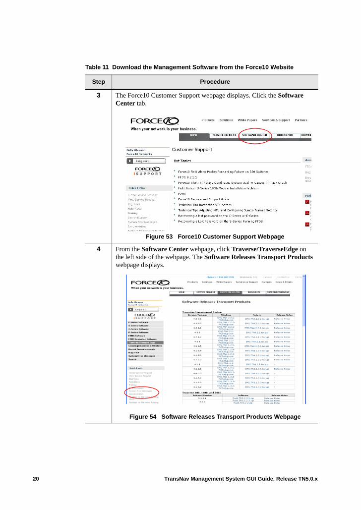
3 The Force10 Customer Support webpage displays. Click the Software Center tab.
Figure 53 Force10 Customer Support Webpage
4 From the Software Center webpage, click Traverse/TraverseEdge on the left side of the webpage. The Software Releases Transport Products webpage displays.
Figure 54 Software Releases Transport Products Webpage
Table 11 Download the Management Software from the Force10 Website
Step Procedure
20 TransNav Management System GUI Guide, Release TN5.0.x
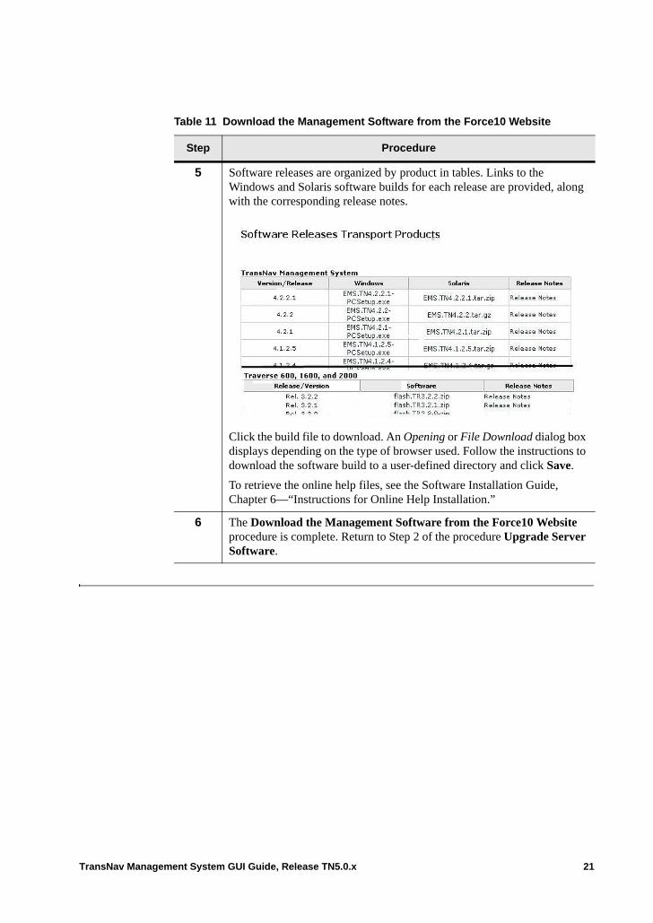
5 Software releases are organized by product in tables. Links to the Windows and Solaris software builds for each release are provided, along with the corresponding release notes.
Click the build file to download. An Opening or File Download dialog box displays depending on the type of browser used. Follow the instructions to download the software build to a user-defined directory and click Save.
To retrieve the online help files, see the Software Installation Guide, Chapter 6—“Instructions for Online Help Installation.”
6 The Download the Management Software from the Force10 Website procedure is complete. Return to Step 2 of the procedure Upgrade Server Software.
Table 11 Download the Management Software from the Force10 Website
Step Procedure
TransNav Management System GUI Guide, Release TN5.0.x 21
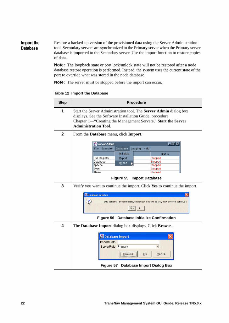
Import the Database
Restore a backed-up version of the provisioned data using the Server Administration tool. Secondary servers are synchronized to the Primary server when the Primary server database is imported to the Secondary server. Use the import function to restore copies of data.
Note: The loopback state or port lock/unlock state will not be restored after a node database restore operation is performed. Instead, the system uses the current state of the port to override what was stored in the node database.
Note: The server must be stopped before the import can occur.
Table 12 Import the Database
Step Procedure
1 Start the Server Administration tool. The Server Admin dialog box displays. See the Software Installation Guide, procedure Chapter 1—“Creating the Management Servers,” Start the Server Administration Tool.
2 From the Database menu, click Import.
Figure 55 Import Database
3 Verify you want to continue the import. Click Yes to continue the import.
Figure 56 Database Initialize Confirmation
4 The Database Import dialog box displays. Click Browse.
Figure 57 Database Import Dialog Box
22 TransNav Management System GUI Guide, Release TN5.0.x
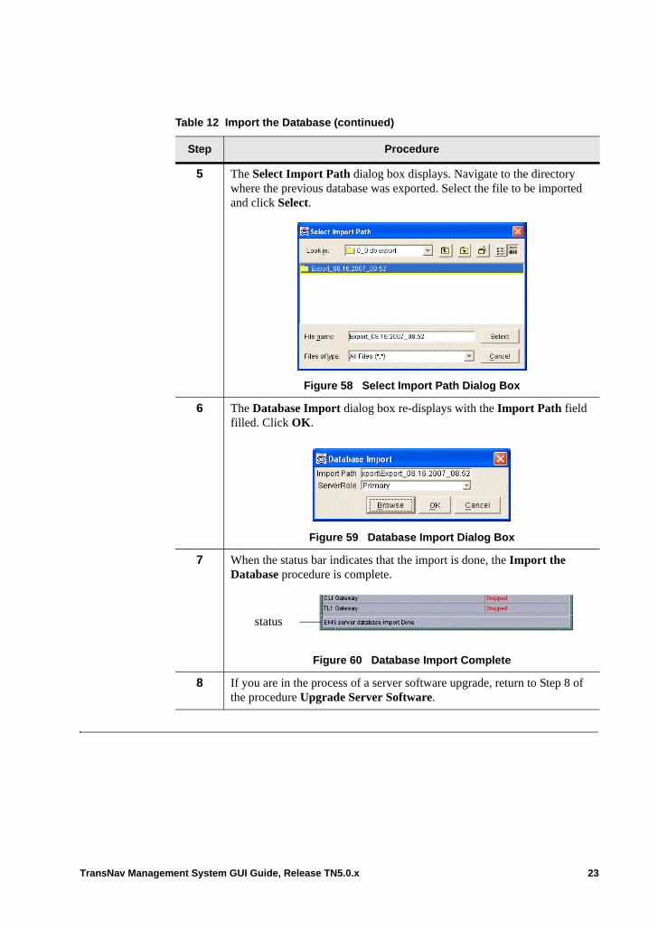
5 The Select Import Path dialog box displays. Navigate to the directory where the previous database was exported. Select the file to be imported and click Select.
Figure 58 Select Import Path Dialog Box
6 The Database Import dialog box re-displays with the Import Path field filled. Click OK.
Figure 59 Database Import Dialog Box
7 When the status bar indicates that the import is done, the Import the Database procedure is complete.
Figure 60 Database Import Complete
8 If you are in the process of a server software upgrade, return to Step 8 of the procedure Upgrade Server Software.
Table 12 Import the Database (continued)
Step Procedure
status
TransNav Management System GUI Guide, Release TN5.0.x 23
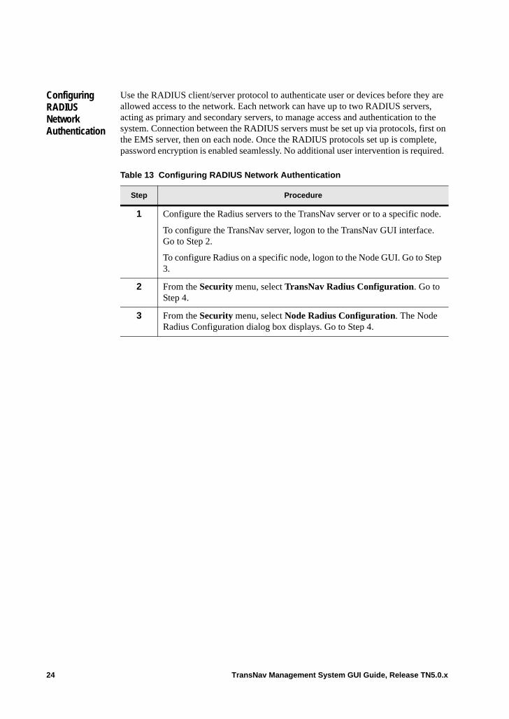
Configuring RADIUS Network Authentication
Use the RADIUS client/server protocol to authenticate user or devices before they are allowed access to the network. Each network can have up to two RADIUS servers, acting as primary and secondary servers, to manage access and authentication to the system. Connection between the RADIUS servers must be set up via protocols, first on the EMS server, then on each node. Once the RADIUS protocols set up is complete, password encryption is enabled seamlessly. No additional user intervention is required.
Table 13 Configuring RADIUS Network Authentication
Step Procedure
1 Configure the Radius servers to the TransNav server or to a specific node.
To configure the TransNav server, logon to the TransNav GUI interface. Go to Step 2.
To configure Radius on a specific node, logon to the Node GUI. Go to Step 3.
2 From the Security menu, select TransNav Radius Configuration. Go to Step 4.
3 From the Security menu, select Node Radius Configuration. The Node Radius Configuration dialog box displays. Go to Step 4.
24 TransNav Management System GUI Guide, Release TN5.0.x
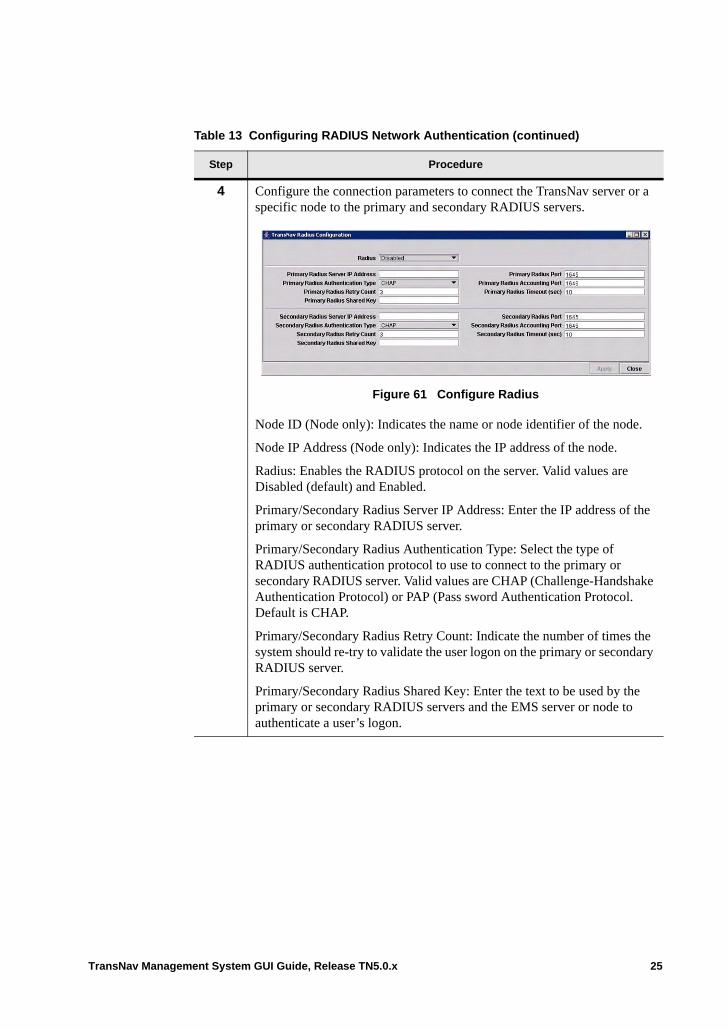
4 Configure the connection parameters to connect the TransNav server or a specific node to the primary and secondary RADIUS servers.
Figure 61 Configure Radius
Node ID (Node only): Indicates the name or node identifier of the node.
Node IP Address (Node only): Indicates the IP address of the node.
Radius: Enables the RADIUS protocol on the server. Valid values are Disabled (default) and Enabled.
Primary/Secondary Radius Server IP Address: Enter the IP address of the primary or secondary RADIUS server.
Primary/Secondary Radius Authentication Type: Select the type of RADIUS authentication protocol to use to connect to the primary or secondary RADIUS server. Valid values are CHAP (Challenge-Handshake Authentication Protocol) or PAP (Pass sword Authentication Protocol. Default is CHAP.
Primary/Secondary Radius Retry Count: Indicate the number of times the system should re-try to validate the user logon on the primary or secondary RADIUS server.
Primary/Secondary Radius Shared Key: Enter the text to be used by the primary or secondary RADIUS servers and the EMS server or node to authenticate a user’s logon.
Table 13 Configuring RADIUS Network Authentication (continued)
Step Procedure
TransNav Management System GUI Guide, Release TN5.0.x 25
Primary/Secondary Radius Port: Indicate the port on the EMS server or node to be used to connect to the primary or secondary RADIUS server. Default is 1645.
Note: For CLI and TL1, SSH is running for both TransNav and the node. For the server CLI, the default SSH port is 7778; for server TL1, the default SSH port is 6252.
Primary/Secondary Radius Accounting Port: Indicate the port on the EMS server or node to be used to connect to the primary or secondary RADIUS server to account for usage of services authorized for use by the RADIUS logon. Default is 1646.
Primary/Secondary Radius Timeout (sec): Indicate in seconds, the amount of time that the connection to the primary or secondary RADIUS server will be attempted before the connection fails. Default is 10 seconds.
5 Click Apply to apply the changes to the node, then click Close to close the dialog box.
Table 13 Configuring RADIUS Network Authentication (continued)
Step Procedure
26 TransNav Management System GUI Guide, Release TN5.0.x
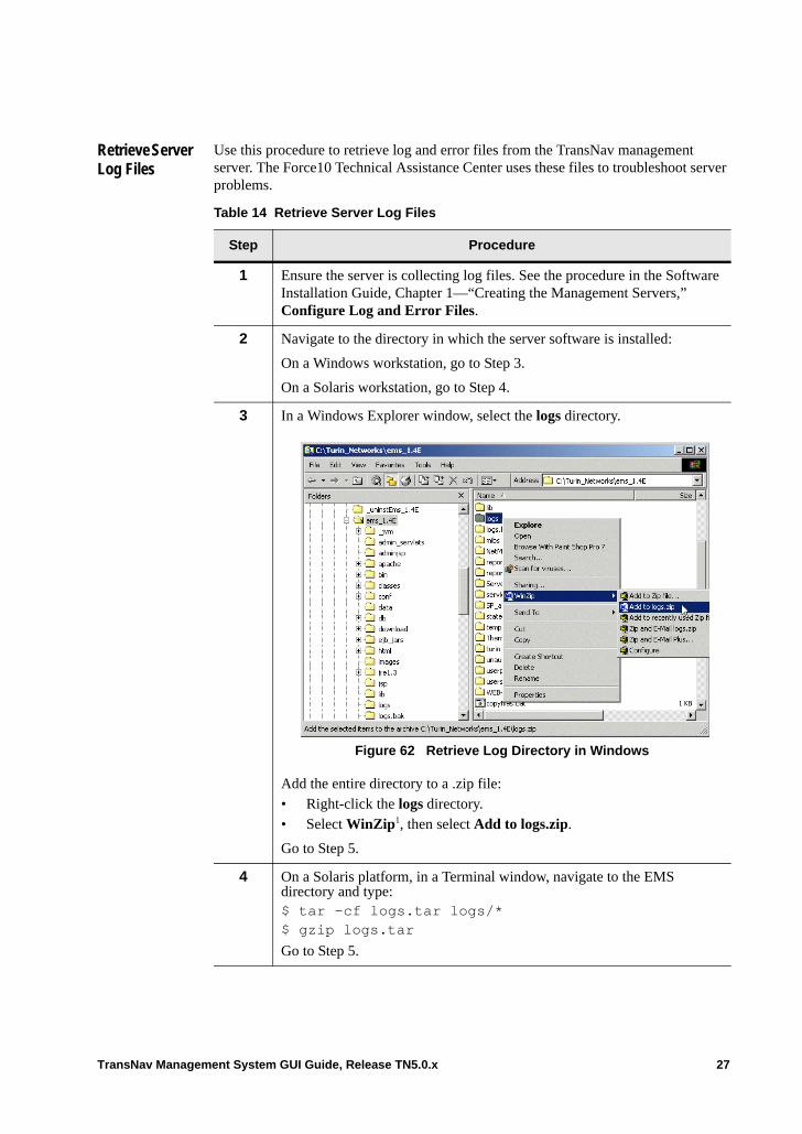
Retrieve Server Log Files
Use this procedure to retrieve log and error files from the TransNav management server. The Force10 Technical Assistance Center uses these files to troubleshoot server problems.
Table 14 Retrieve Server Log Files
Step Procedure
1 Ensure the server is collecting log files. See the procedure in the Software Installation Guide, Chapter 1—“Creating the Management Servers,” Configure Log and Error Files.
2 Navigate to the directory in which the server software is installed:
On a Windows workstation, go to Step 3.
On a Solaris workstation, go to Step 4.
3 In a Windows Explorer window, select the logs directory.
Figure 62 Retrieve Log Directory in Windows
Add the entire directory to a .zip file:• Right-click the logs directory.• Select WinZip1, then select Add to logs.zip.
Go to Step 5.
4 On a Solaris platform, in a Terminal window, navigate to the EMS directory and type:$ tar -cf logs.tar logs/*$ gzip logs.tar
Go to Step 5.
TransNav Management System GUI Guide, Release TN5.0.x 27
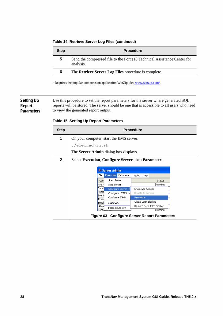
Setting Up Report Parameters
Use this procedure to set the report parameters for the server where generated SQL reports will be stored. The server should be one that is accessible to all users who need to view the generated report output.
5 Send the compressed file to the Force10 Technical Assistance Center for analysis.
6 The Retrieve Server Log Files procedure is complete.
1 Requires the popular compression application WinZip. See www.winzip.com/.
Table 14 Retrieve Server Log Files (continued)
Step Procedure
Table 15 Setting Up Report Parameters
Step Procedure
1 On your computer, start the EMS server:
./exec_admin.sh
The Server Admin dialog box displays.
2 Select Execution, Configure Server, then Parameter.
Figure 63 Configure Server Report Parameters
28 TransNav Management System GUI Guide, Release TN5.0.x
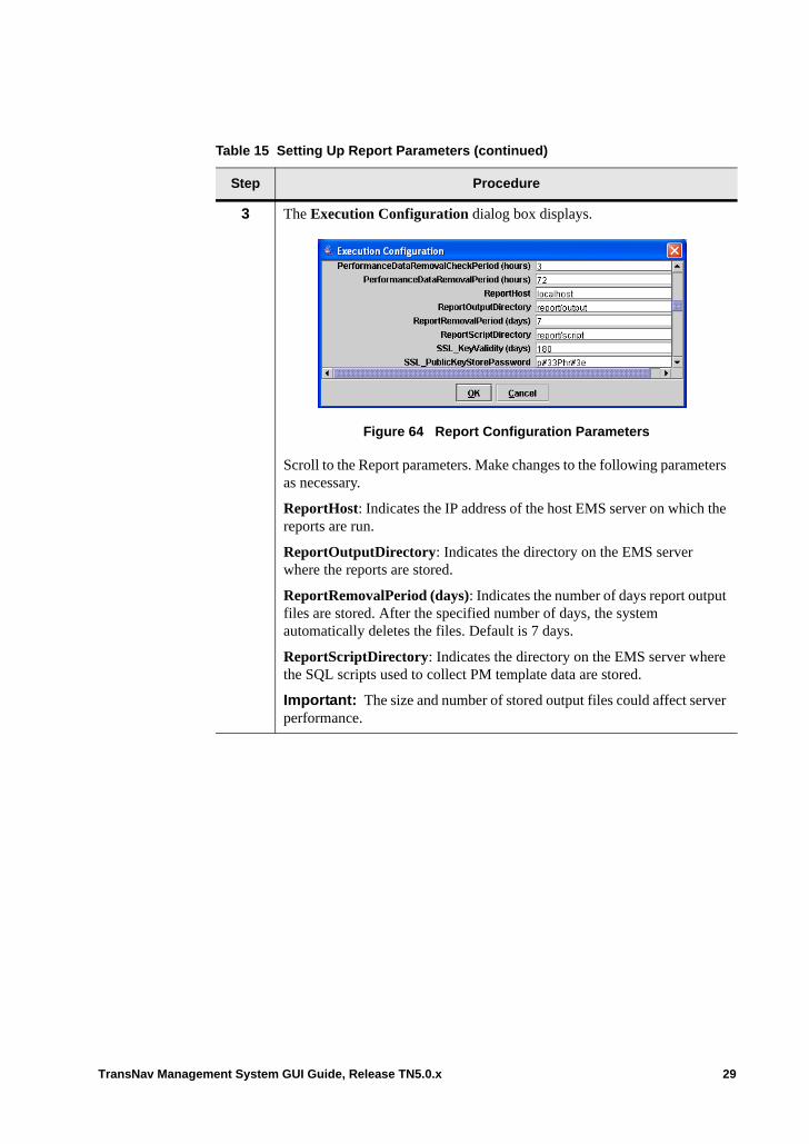
3 The Execution Configuration dialog box displays.
Figure 64 Report Configuration Parameters
Scroll to the Report parameters. Make changes to the following parameters as necessary.
ReportHost: Indicates the IP address of the host EMS server on which the reports are run.
ReportOutputDirectory: Indicates the directory on the EMS server where the reports are stored.
ReportRemovalPeriod (days): Indicates the number of days report output files are stored. After the specified number of days, the system automatically deletes the files. Default is 7 days.
ReportScriptDirectory: Indicates the directory on the EMS server where the SQL scripts used to collect PM template data are stored.
Important: The size and number of stored output files could affect server performance.
Table 15 Setting Up Report Parameters (continued)
Step Procedure
TransNav Management System GUI Guide, Release TN5.0.x 29
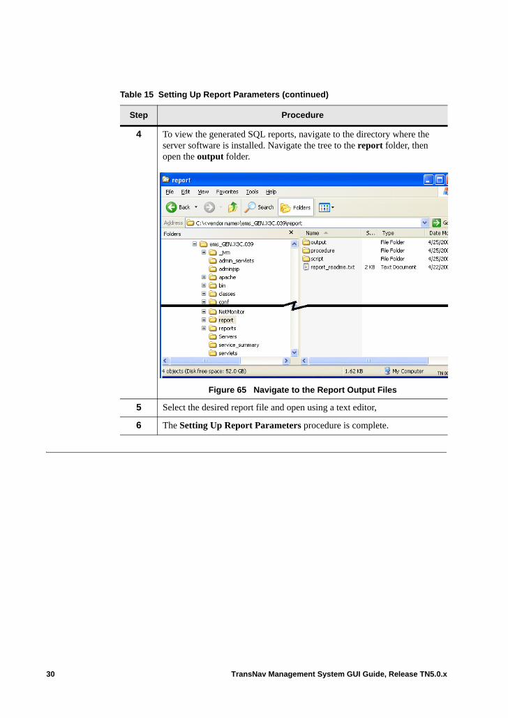
4 To view the generated SQL reports, navigate to the directory where the server software is installed. Navigate the tree to the report folder, then open the output folder.
Figure 65 Navigate to the Report Output Files
5 Select the desired report file and open using a text editor,
6 The Setting Up Report Parameters procedure is complete.
Table 15 Setting Up Report Parameters (continued)
Step Procedure
30 TransNav Management System GUI Guide, Release TN5.0.x
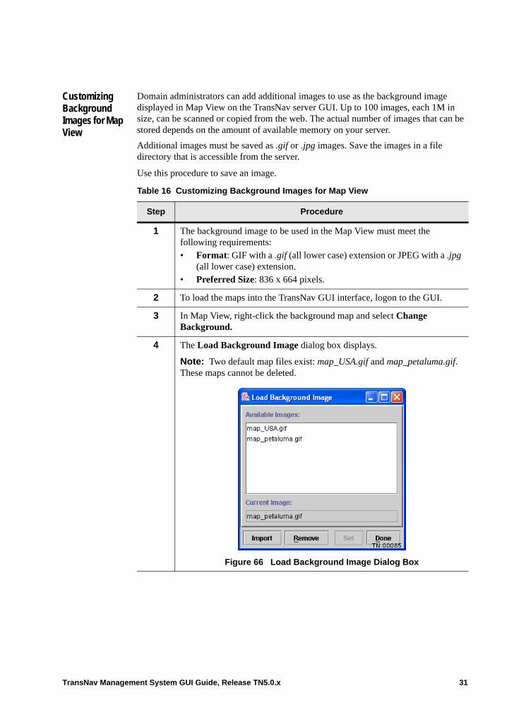
Customizing Background Images for Map View
Domain administrators can add additional images to use as the background image displayed in Map View on the TransNav server GUI. Up to 100 images, each 1M in size, can be scanned or copied from the web. The actual number of images that can be stored depends on the amount of available memory on your server.
Additional images must be saved as .gif or .jpg images. Save the images in a file directory that is accessible from the server.
Use this procedure to save an image.
Table 16 Customizing Background Images for Map View
Step Procedure
1 The background image to be used in the Map View must meet the following requirements:• Format: GIF with a .gif (all lower case) extension or JPEG with a .jpg
(all lower case) extension.• Preferred Size: 836 x 664 pixels.
2 To load the maps into the TransNav GUI interface, logon to the GUI.
3 In Map View, right-click the background map and select Change Background.
4 The Load Background Image dialog box displays.
Note: Two default map files exist: map_USA.gif and map_petaluma.gif. These maps cannot be deleted.
Figure 66 Load Background Image Dialog Box
TransNav Management System GUI Guide, Release TN5.0.x 31
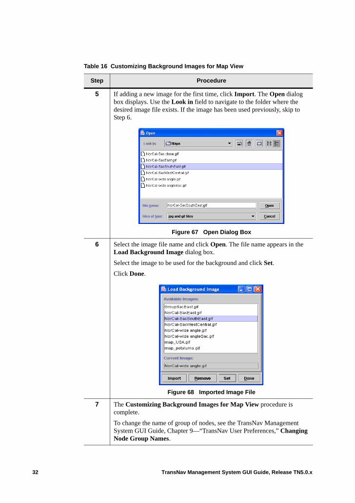
5 If adding a new image for the first time, click Import. The Open dialog box displays. Use the Look in field to navigate to the folder where the desired image file exists. If the image has been used previously, skip to Step 6.
Figure 67 Open Dialog Box
6 Select the image file name and click Open. The file name appears in the Load Background Image dialog box.
Select the image to be used for the background and click Set.
Click Done.
Figure 68 Imported Image File
7 The Customizing Background Images for Map View procedure is complete.
To change the name of group of nodes, see the TransNav Management System GUI Guide, Chapter 9—“TransNav User Preferences,” Changing Node Group Names.
Table 16 Customizing Background Images for Map View
Step Procedure
32 TransNav Management System GUI Guide, Release TN5.0.x
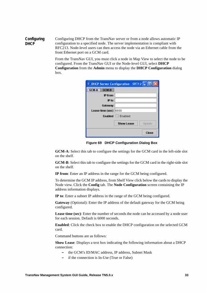
Configuring DHCP
Configuring DHCP from the TransNav server or from a node allows automatic IP configuration to a specified node. The server implementation is compliant with RFC213. Node-level users can then access the node via an Ethernet cable from the front Ethernet port on a GCM card.
From the TransNav GUI, you must click a node in Map View to select the node to be configured. From the TransNav GUI or the Node-level GUI, select DHCP Configuration from the Admin menu to display the DHCP Configuration dialog box.
Figure 69 DHCP Configuration Dialog Box
GCM-A: Select this tab to configure the settings for the GCM card in the left-side slot on the shelf.
GCM-B: Select this tab to configure the settings for the GCM card in the right-side slot on the shelf.
IP from: Enter an IP address in the range for the GCM being configured.
To determine the GCM IP address, from Shelf View click below the cards to display the Node view. Click the Config tab. The Node Configuration screen containing the IP address information displays.
IP to: Enter a subnet IP address in the range of the GCM being configured.
Gateway (Optional): Enter the IP address of the default gateway for the GCM being configured.
Lease time (sec): Enter the number of seconds the node can be accessed by a node user for each session. Default is 6000 seconds.
Enabled: Click the check box to enable the DHCP configuration on the selected GCM card.
Command buttons are as follows:
Show Lease: Displays a text box indicating the following information about a DHCP connection:
– the GCM’s ID/MAC address, IP address, Subnet Mask – if the connection is In-Use (True or False)
TransNav Management System GUI Guide, Release TN5.0.x 33
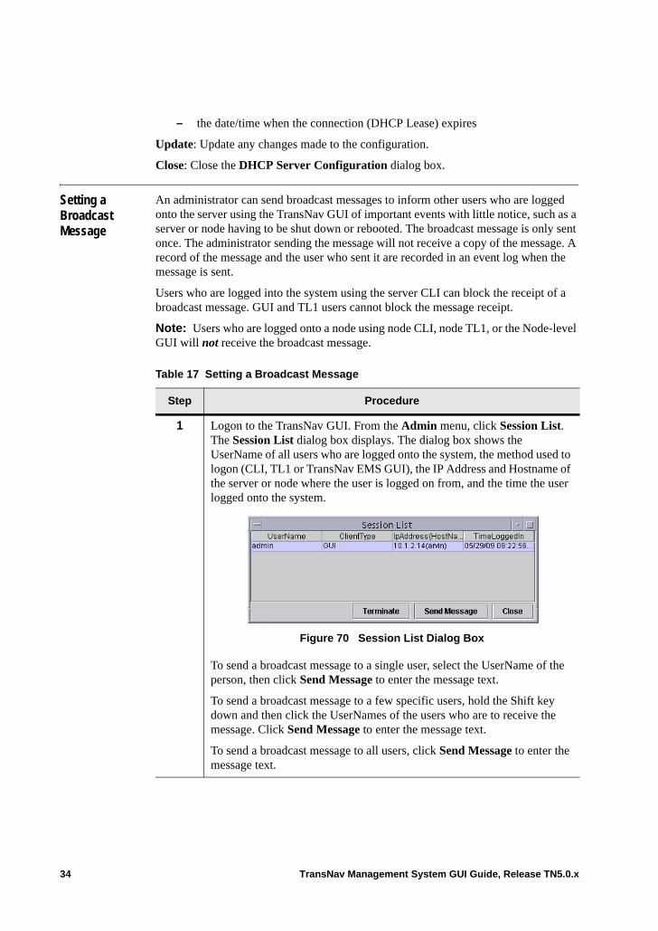
– the date/time when the connection (DHCP Lease) expires
Update: Update any changes made to the configuration.
Close: Close the DHCP Server Configuration dialog box.
Setting a Broadcast Message
An administrator can send broadcast messages to inform other users who are logged onto the server using the TransNav GUI of important events with little notice, such as a server or node having to be shut down or rebooted. The broadcast message is only sent once. The administrator sending the message will not receive a copy of the message. A record of the message and the user who sent it are recorded in an event log when the message is sent.
Users who are logged into the system using the server CLI can block the receipt of a broadcast message. GUI and TL1 users cannot block the message receipt.
Note: Users who are logged onto a node using node CLI, node TL1, or the Node-level GUI will not receive the broadcast message.
Table 17 Setting a Broadcast Message
Step Procedure
1 Logon to the TransNav GUI. From the Admin menu, click Session List. The Session List dialog box displays. The dialog box shows the UserName of all users who are logged onto the system, the method used to logon (CLI, TL1 or TransNav EMS GUI), the IP Address and Hostname of the server or node where the user is logged on from, and the time the user logged onto the system.
Figure 70 Session List Dialog Box
To send a broadcast message to a single user, select the UserName of the person, then click Send Message to enter the message text.
To send a broadcast message to a few specific users, hold the Shift key down and then click the UserNames of the users who are to receive the message. Click Send Message to enter the message text.
To send a broadcast message to all users, click Send Message to enter the message text.
34 TransNav Management System GUI Guide, Release TN5.0.x
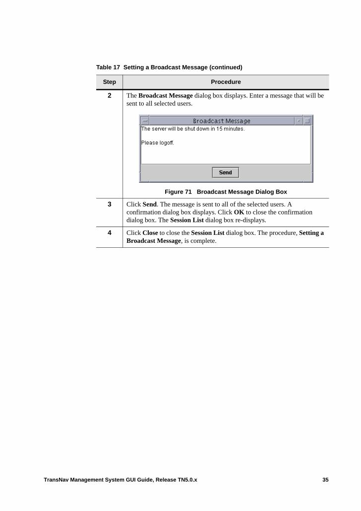
2 The Broadcast Message dialog box displays. Enter a message that will be sent to all selected users.
Figure 71 Broadcast Message Dialog Box
3 Click Send. The message is sent to all of the selected users. A confirmation dialog box displays. Click OK to close the confirmation dialog box. The Session List dialog box re-displays.
4 Click Close to close the Session List dialog box. The procedure, Setting a Broadcast Message, is complete.
Table 17 Setting a Broadcast Message (continued)
Step Procedure
TransNav Management System GUI Guide, Release TN5.0.x 35
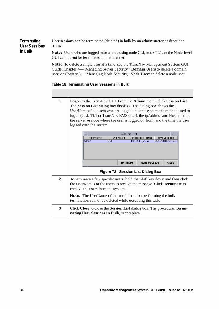
Terminating User Sessions in Bulk
User sessions can be terminated (deleted) in bulk by an administrator as described below.
Note: Users who are logged onto a node using node CLI, node TL1, or the Node-level GUI cannot not be terminated in this manner.
Note: To delete a single user at a time, see the TransNav Management System GUI Guide, Chapter 4—“Managing Server Security,” Domain Users to delete a domain user, or Chapter 5—“Managing Node Security,” Node Users to delete a node user.
Table 18 Terminating User Sessions in Bulk
1 Logon to the TransNav GUI. From the Admin menu, click Session List. The Session List dialog box displays. The dialog box shows the UserName of all users who are logged onto the system, the method used to logon (CLI, TL1 or TransNav EMS GUI), the ipAddress and Hostname of the server or node where the user is logged on from, and the time the user logged onto the system.
Figure 72 Session List Dialog Box
2 To terminate a few specific users, hold the Shift key down and then click the UserNames of the users to receive the message. Click Terminate to remove the users from the system.
Note: The UserName of the administration performing the bulk termination cannot be deleted while executing this task.
3 Click Close to close the Session List dialog box. The procedure, Termi-nating User Sessions in Bulk, is complete.
36 TransNav Management System GUI Guide, Release TN5.0.x
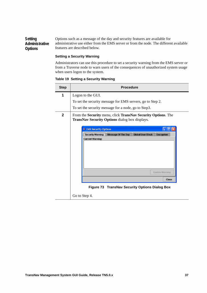
Setting Administrative Options
Options such as a message of the day and security features are available for administrative use either from the EMS server or from the node. The different available features are described below.
Setting a Security Warning
Administrators can use this procedure to set a security warning from the EMS server or from a Traverse node to warn users of the consequences of unauthorized system usage when users logon to the system.
Table 19 Setting a Security Warning
Step Procedure
1 Logon to the GUI.
To set the security message for EMS servers, go to Step 2.
To set the security message for a node, go to Step3.
2 From the Security menu, click TransNav Security Options. The TransNav Security Options dialog box displays.
Figure 73 TransNav Security Options Dialog Box
Go to Step 4.
TransNav Management System GUI Guide, Release TN5.0.x 37
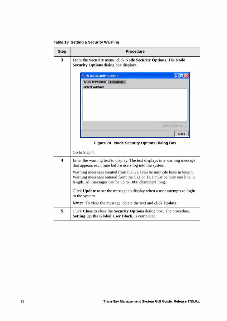
3 From the Security menu, click Node Security Options. The Node Security Options dialog box displays.
Figure 74 Node Security Options Dialog Box
Go to Step 4.
4 Enter the warning text to display. The text displays in a warning message that appears each time before users log into the system.
Warning messages created from the GUI can be multiple lines in length. Warning messages entered from the CLI or TL1 must be only one line in length. All messages can be up to 1000 characters long.
Click Update to set the message to display when a user attempts to login to the system.
Note: To clear the message, delete the text and click Update.
5 Click Close to close the Security Options dialog box. The procedure, Setting Up the Global User Block, is completed.
Table 19 Setting a Security Warning
Step Procedure
38 TransNav Management System GUI Guide, Release TN5.0.x
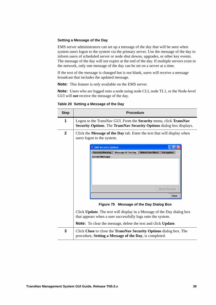
Setting a Message of the Day
EMS server administrators can set up a message of the day that will be seen when system users logon to the system via the primary server. Use the message of the day to inform users of scheduled server or node shut downs, upgrades, or other key events. The message of the day will not expire at the end of the day. If multiple servers exist in the network, only one message of the day can be set on a server at a time.
If the text of the message is changed but is not blank, users will receive a message broadcast that includes the updated message.
Note: This feature is only available on the EMS server.
Note: Users who are logged onto a node using node CLI, node TL1, or the Node-level GUI will not receive the message of the day.
Table 20 Setting a Message of the Day
Step Procedure
1 Logon to the TransNav GUI. From the Security menu, click TransNav Security Options. The TransNav Security Options dialog box displays.
2 Click the Message of the Day tab. Enter the text that will display when users logon to the system.
Figure 75 Message of the Day Dialog Box
Click Update. The text will display in a Message of the Day dialog box that appears when a user successfully logs onto the system.
Note: To clear the message, delete the text and click Update.
3 Click Close to close the TransNav Security Options dialog box. The procedure, Setting a Message of the Day, is completed.
TransNav Management System GUI Guide, Release TN5.0.x 39
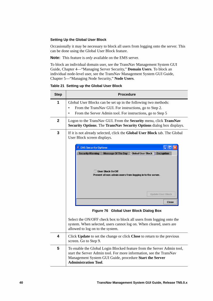
Setting Up the Global User Block
Occasionally it may be necessary to block all users from logging onto the server. This can be done using the Global User Block feature.
Note: This feature is only available on the EMS server.
To block an individual domain user, see the TransNav Management System GUI Guide, Chapter 4—“Managing Server Security,” Domain Users. To block an individual node-level user, see the TransNav Management System GUI Guide, Chapter 5—“Managing Node Security,” Node Users.
Table 21 Setting up the Global User Block
Step Procedure
1 Global User Blocks can be set up in the following two methods: • From the TransNav GUI. For instructions, go to Step 2.• From the Server Admin tool. For instructions, go to Step 5
2 Logon to the TransNav GUI. From the Security menu, click TransNav Security Options. The TransNav Security Options dialog box displays.
3 If it is not already selected, click the Global User Block tab. The Global User Block screen displays.
Figure 76 Global User Block Dialog Box
Select the ON/OFF check box to block all users from logging onto the system. When selected, users cannot log on. When cleared, users are allowed to log on to the system.
4 Click Update to set the change or click Close to return to the previous screen. Go to Step 9.
5 To enable the Global Login Blocked feature from the Server Admin tool, start the Server Admin tool. For more information, see the TransNav Management System GUI Guide, procedure Start the Server Administration Tool.
40 TransNav Management System GUI Guide, Release TN5.0.x
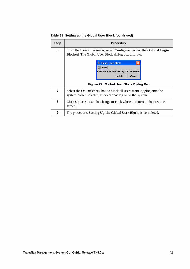
6 From the Execution menu, select Configure Server, then Global Login Blocked. The Global User Block dialog box displays.
Figure 77 Global User Block Dialog Box
7 Select the On/Off check box to block all users from logging onto the system. When selected, users cannot log on to the system.
8 Click Update to set the change or click Close to return to the previous screen.
9 The procedure, Setting Up the Global User Block, is completed.
Table 21 Setting up the Global User Block (continued)
Step Procedure
TransNav Management System GUI Guide, Release TN5.0.x 41
Enabling Encryption
Server and Node administrators can use the encryption feature to secure the following types of management links between the TransNav and Node GUI clients and the TransNav EMS server and a Traverse system: • Connections between the TransNav GUI and Node GUI to the TransNav server and
the Traverse system.• Telnet connections between the TransNav server and node CLI and TL1
connections to TransNav and the Traverse system.• CLI connections (via SSHv2)• HTTPS connection between the TransNav GUI and TransNav server
When a RADIUS server is configured and enabled in the network for user authentication, the system will authenticate the user account using its local database or the RADIUS server configuration.
Note: When encryption is set for CLI and TL1, the existing telnet connections will be terminated. All future connections will use the encrypted communication channels.
Table 22 Setting up the Encryption
Step Procedure
1 Encryption can be enabled on the TransNav server or on a node. See the following instructions:• To enable encryption on the server, go to Step 2.• To enable encryption on a node, go to Step 6
2 Logon to the TransNav GUI. From the Security menu, click TransNav Security Options. The TransNav Security Options dialog box displays.
Go to Step 4.
3 Logon to the Node GUI. From the Security menu, click Node Security Options. The Node Security Options dialog box displays.
Go to Step 4.
42 TransNav Management System GUI Guide, Release TN5.0.x
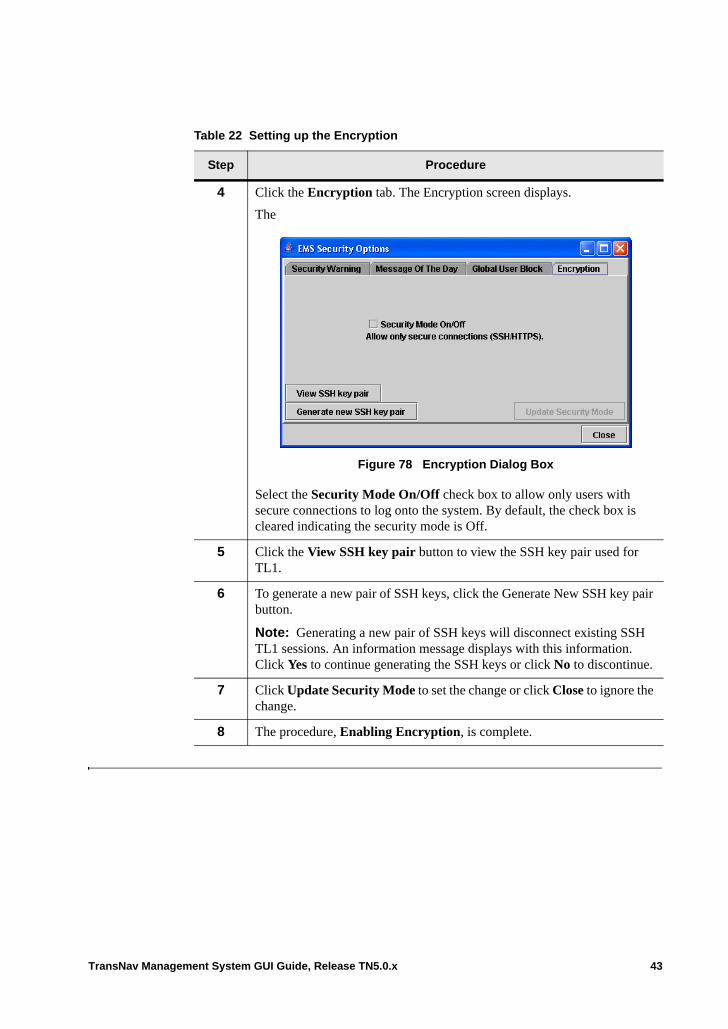
4 Click the Encryption tab. The Encryption screen displays.
The
Figure 78 Encryption Dialog Box
Select the Security Mode On/Off check box to allow only users with secure connections to log onto the system. By default, the check box is cleared indicating the security mode is Off.
5 Click the View SSH key pair button to view the SSH key pair used for TL1.
6 To generate a new pair of SSH keys, click the Generate New SSH key pair button.
Note: Generating a new pair of SSH keys will disconnect existing SSH TL1 sessions. An information message displays with this information. Click Yes to continue generating the SSH keys or click No to discontinue.
7 Click Update Security Mode to set the change or click Close to ignore the change.
8 The procedure, Enabling Encryption, is complete.
Table 22 Setting up the Encryption
Step Procedure
TransNav Management System GUI Guide, Release TN5.0.x 43
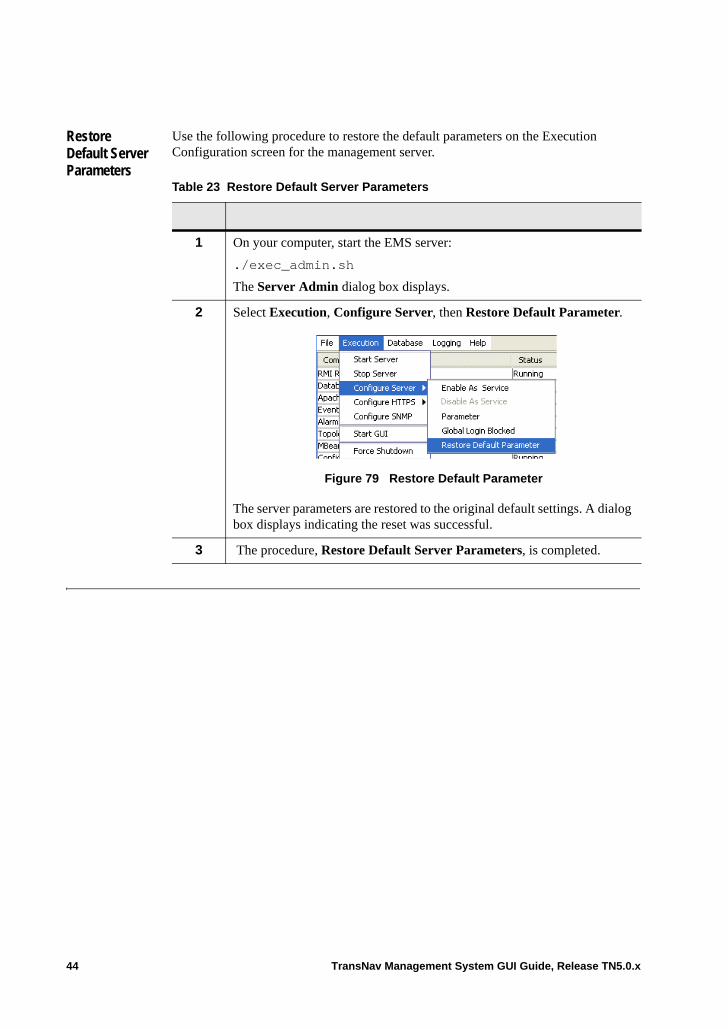
Restore Default Server Parameters
Use the following procedure to restore the default parameters on the Execution Configuration screen for the management server.
Table 23 Restore Default Server Parameters
1 On your computer, start the EMS server:
./exec_admin.sh
The Server Admin dialog box displays.
2 Select Execution, Configure Server, then Restore Default Parameter.
Figure 79 Restore Default Parameter
The server parameters are restored to the original default settings. A dialog box displays indicating the reset was successful.
3 The procedure, Restore Default Server Parameters, is completed.
44 TransNav Management System GUI Guide, Release TN5.0.x
Chapter 4 Managing Server Security
Introduction Security management enables the network operator to create and manage user accounts with specific access privileges. Security management also tracks user account activity to assist in identifying and preventing security breaches. For an overview of security management, see the Overview Guide, Chapter 2—“Network Management Features.”
This chapter explains changing a password, roles, functional groups, and assigning access rights to domain users:• Password Changes• Guidelines to Managing Server Security• Domain User Access Roles• Domain Users• Functional Groups• Session List
Definitions A domain refers to an entire Traverse network. The terms domain and management domain are used interchangeably.
A management plane domain is a set of Traverse nodes managed by a common TransNav system.
A Functional Group is a user-defined combination of access roles enabling domain users access to assigned Traverse nodes.
A Role is based on the responsibilities that network operation personnel have in their network; for example, Equipment Configuration Manager.
TransNav Management System GUI Guide, Release TN5.0.x 1
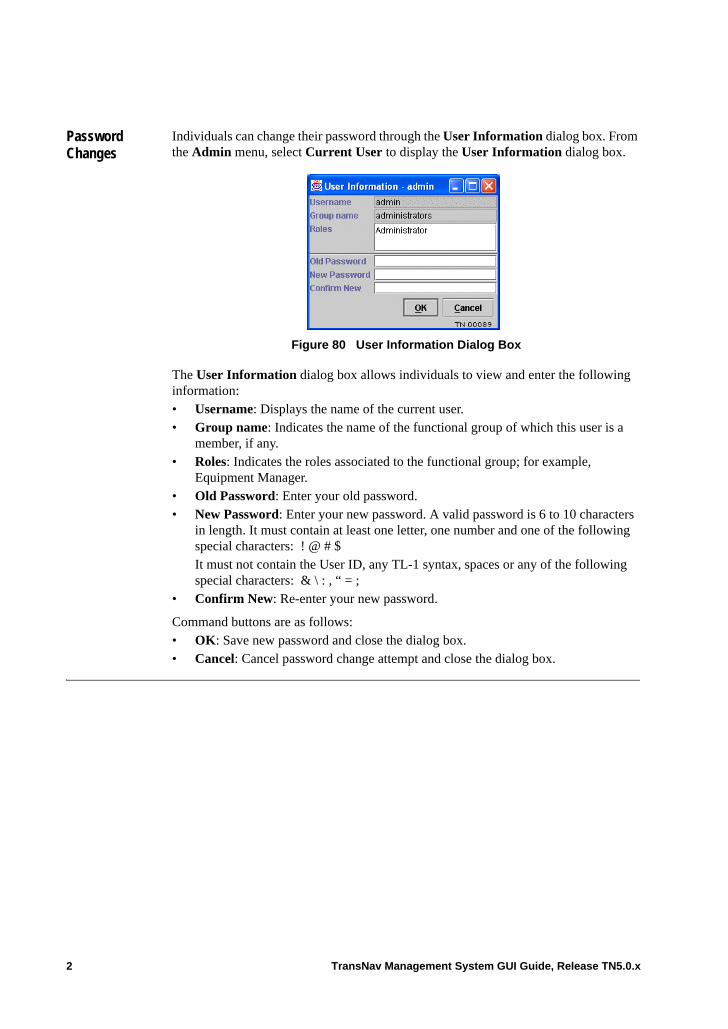
Password Changes
Individuals can change their password through the User Information dialog box. From the Admin menu, select Current User to display the User Information dialog box.
Figure 80 User Information Dialog Box
The User Information dialog box allows individuals to view and enter the following information:• Username: Displays the name of the current user. • Group name: Indicates the name of the functional group of which this user is a
member, if any.• Roles: Indicates the roles associated to the functional group; for example,
Equipment Manager.• Old Password: Enter your old password.• New Password: Enter your new password. A valid password is 6 to 10 characters
in length. It must contain at least one letter, one number and one of the following special characters: ! @ # $It must not contain the User ID, any TL-1 syntax, spaces or any of the following special characters: & \ : , “ = ;
• Confirm New: Re-enter your new password.
Command buttons are as follows:• OK: Save new password and close the dialog box.• Cancel: Cancel password change attempt and close the dialog box.
2 TransNav Management System GUI Guide, Release TN5.0.x
Guidelines to Managing Server Security
The guidelines to managing server security are:• For security reasons, only Administrators can add new users at the domain level.
The User Manager role is available at the node-level only.• If you do not specify a role when you create a user account, by default the user has
only viewing privileges. The Viewer role is not directly provisionable.• Domain users can only be assigned to one Functional Group per logon username
and password. A separate logon username and password is required if access is needed to another functional group.
• If All Nodes is selected for a functional group, the users in that functional group will have access to all nodes in the network. This is required for roles, such as Equipment Configuration Managers, who must have All Nodes assigned to display protection ring information for the network. It is also required for provisioning end-to-end services.
• A secure HTTP setting can be enabled on the server during setup that is available only for clients attached to a server. Setup requires enabling an HTTPS server key on the server and enabling the client IP address on the server. Client users must enter the IP address of the server that has HTTPS enabled. For information on setting up the HTTPS server key, see the Software Installation Guide, Chapter 1—“Creating the Management Servers,” Configure HTTPS.
TransNav Management System GUI Guide, Release TN5.0.x 3
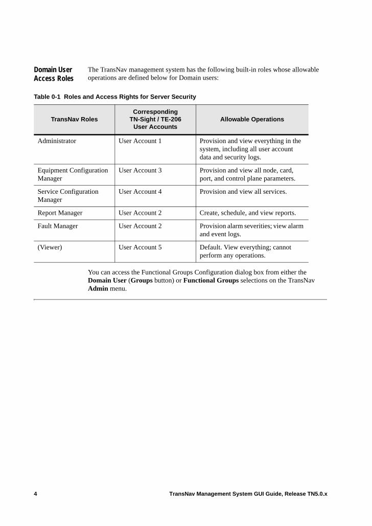
Domain User Access Roles
The TransNav management system has the following built-in roles whose allowable operations are defined below for Domain users:
You can access the Functional Groups Configuration dialog box from either the Domain User (Groups button) or Functional Groups selections on the TransNav Admin menu.
Table 0-1 Roles and Access Rights for Server Security
TransNav RolesCorresponding
TN-Sight / TE-206 User Accounts
Allowable Operations
Administrator User Account 1 Provision and view everything in the system, including all user account data and security logs.
Equipment Configuration Manager
User Account 3 Provision and view all node, card, port, and control plane parameters.
Service Configuration Manager
User Account 4 Provision and view all services.
Report Manager User Account 2 Create, schedule, and view reports.
Fault Manager User Account 2 Provision alarm severities; view alarm and event logs.
(Viewer) User Account 5 Default. View everything; cannot perform any operations.
4 TransNav Management System GUI Guide, Release TN5.0.x
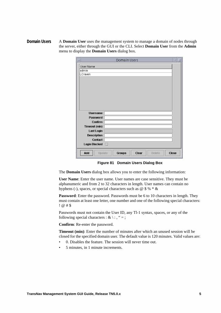
Domain Users A Domain User uses the management system to manage a domain of nodes through the server, either through the GUI or the CLI. Select Domain User from the Admin menu to display the Domain Users dialog box.
Figure 81 Domain Users Dialog Box
The Domain Users dialog box allows you to enter the following information:
User Name: Enter the user name. User names are case sensitive. They must be alphanumeric and from 2 to 32 characters in length. User names can contain no hyphens (-), spaces, or special characters such as @ $ % * &
Password: Enter the password. Passwords must be 6 to 10 characters in length. They must contain at least one letter, one number and one of the following special characters: ! @ # $
Passwords must not contain the User ID, any Tl-1 syntax, spaces, or any of the following special characters : & \ : , “ = ;
Confirm: Re-enter the password.
Timeout (min): Enter the number of minutes after which an unused session will be closed for the specified domain user. The default value is 120 minutes. Valid values are: • 0. Disables the feature. The session will never time out. • 5 minutes, in 1 minute increments.
TransNav Management System GUI Guide, Release TN5.0.x 5
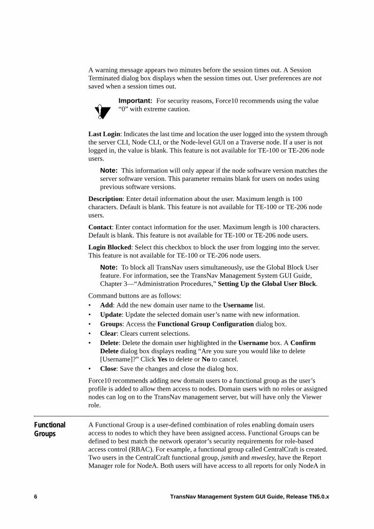
A warning message appears two minutes before the session times out. A Session Terminated dialog box displays when the session times out. User preferences are not saved when a session times out.
Last Login: Indicates the last time and location the user logged into the system through the server CLI, Node CLI, or the Node-level GUI on a Traverse node. If a user is not logged in, the value is blank. This feature is not available for TE-100 or TE-206 node users.
Note: This information will only appear if the node software version matches the server software version. This parameter remains blank for users on nodes using previous software versions.
Description: Enter detail information about the user. Maximum length is 100 characters. Default is blank. This feature is not available for TE-100 or TE-206 node users.
Contact: Enter contact information for the user. Maximum length is 100 characters. Default is blank. This feature is not available for TE-100 or TE-206 node users.
Login Blocked: Select this checkbox to block the user from logging into the server. This feature is not available for TE-100 or TE-206 node users.
Note: To block all TransNav users simultaneously, use the Global Block User feature. For information, see the TransNav Management System GUI Guide, Chapter 3—“Administration Procedures,” Setting Up the Global User Block.
Command buttons are as follows:• Add: Add the new domain user name to the Username list.• Update: Update the selected domain user’s name with new information.• Groups: Access the Functional Group Configuration dialog box. • Clear: Clears current selections.• Delete: Delete the domain user highlighted in the Username box. A Confirm
Delete dialog box displays reading “Are you sure you would like to delete [Username]?” Click Yes to delete or No to cancel.
• Close: Save the changes and close the dialog box.
Force10 recommends adding new domain users to a functional group as the user’s profile is added to allow them access to nodes. Domain users with no roles or assigned nodes can log on to the TransNav management server, but will have only the Viewer role.
Functional Groups
A Functional Group is a user-defined combination of roles enabling domain users access to nodes to which they have been assigned access. Functional Groups can be defined to best match the network operator’s security requirements for role-based access control (RBAC). For example, a functional group called CentralCraft is created. Two users in the CentralCraft functional group, jsmith and mwesley, have the Report Manager role for NodeA. Both users will have access to all reports for only NodeA in
Important: For security reasons, Force10 recommends using the value “0” with extreme caution.
6 TransNav Management System GUI Guide, Release TN5.0.x
the CentralCraft functional group; they cannot access reports for the any other nodes in the CentralCraft functional group. If you are a domain user with Administrator role rights, you can create and maintain functional groups from the Admin menu by selecting Functional Groups or the Domain User, Groups command button.
Figure 82 Functional Group Configuration Dialog Box
The Functional Group Configuration dialog box allows you to enter the following information:
Functional Group Name: Click the field to enter the name of the functional group. The name must be alphanumeric and contain no spaces. Hyphens (-) are allowed.
Note: The administrators functional group is built-in; it cannot be changed or deleted. The password for this functional group may be changed (and should be for security reasons).
Roles: Select the roles to be included in the functional group. The roles are:• Administrator• Service Configuration Manager• Fault Manager• Equipment Configuration Manager• Report Manager
All Nodes: Select to assign all nodes to the functional group. Users whose roles require end-to-end provisioning must have All Nodes selected.
Node List: Select a node from the list below and click the right arrow to assign the node to the functional group.
User List: Select the username from the list below and click the right arrow to assign the user to the functional group.
TransNav Management System GUI Guide, Release TN5.0.x 7
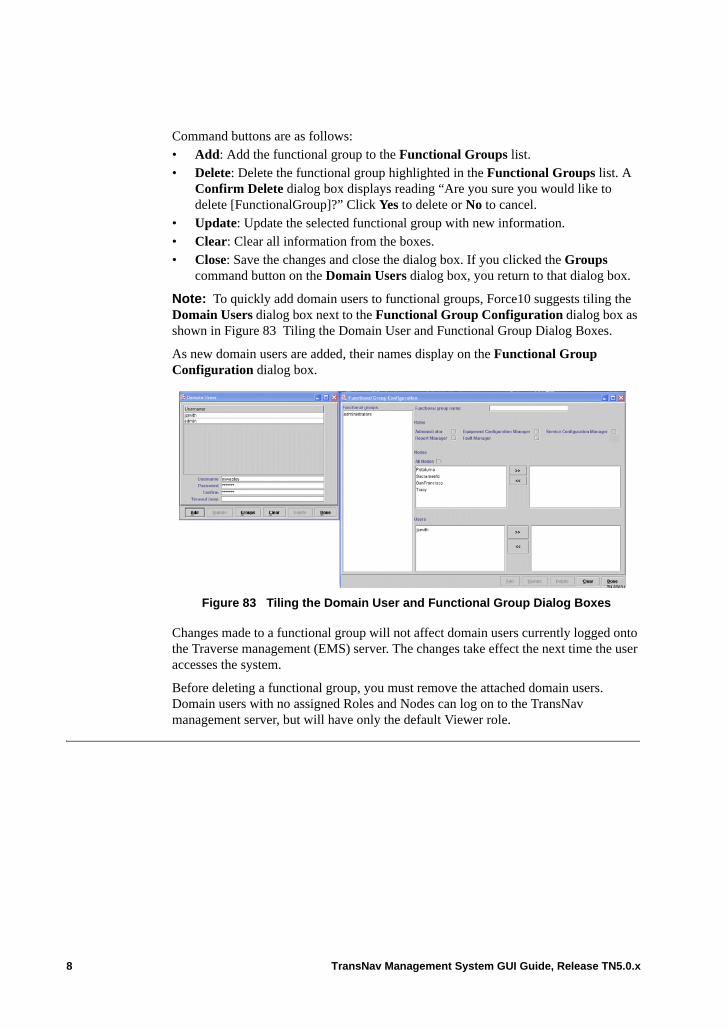
Command buttons are as follows:• Add: Add the functional group to the Functional Groups list.• Delete: Delete the functional group highlighted in the Functional Groups list. A
Confirm Delete dialog box displays reading “Are you sure you would like to delete [FunctionalGroup]?” Click Yes to delete or No to cancel.
• Update: Update the selected functional group with new information.• Clear: Clear all information from the boxes.• Close: Save the changes and close the dialog box. If you clicked the Groups
command button on the Domain Users dialog box, you return to that dialog box.
Note: To quickly add domain users to functional groups, Force10 suggests tiling the Domain Users dialog box next to the Functional Group Configuration dialog box as shown in Figure 83 Tiling the Domain User and Functional Group Dialog Boxes.
As new domain users are added, their names display on the Functional Group Configuration dialog box.
Figure 83 Tiling the Domain User and Functional Group Dialog Boxes
Changes made to a functional group will not affect domain users currently logged onto the Traverse management (EMS) server. The changes take effect the next time the user accesses the system.
Before deleting a functional group, you must remove the attached domain users. Domain users with no assigned Roles and Nodes can log on to the TransNav management server, but will have only the default Viewer role.
8 TransNav Management System GUI Guide, Release TN5.0.x
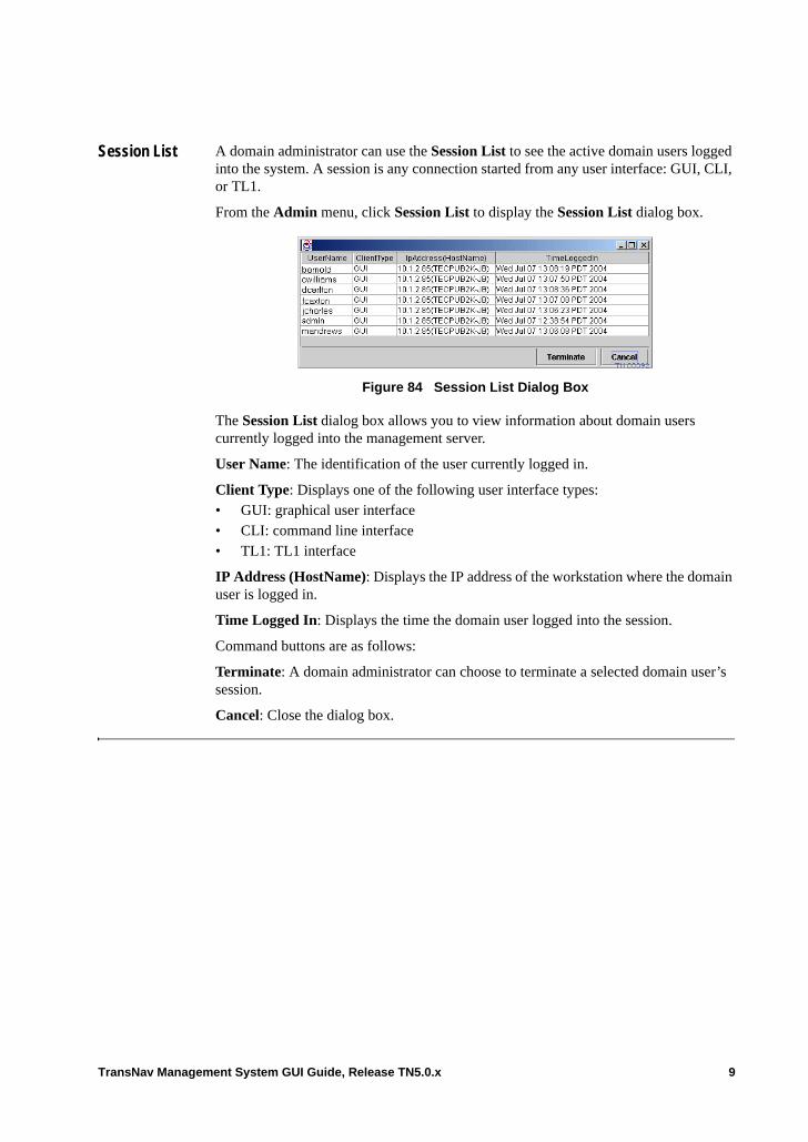
Session List A domain administrator can use the Session List to see the active domain users logged into the system. A session is any connection started from any user interface: GUI, CLI, or TL1.
From the Admin menu, click Session List to display the Session List dialog box.
Figure 84 Session List Dialog Box
The Session List dialog box allows you to view information about domain users currently logged into the management server.
User Name: The identification of the user currently logged in.
Client Type: Displays one of the following user interface types:• GUI: graphical user interface• CLI: command line interface• TL1: TL1 interface
IP Address (HostName): Displays the IP address of the workstation where the domain user is logged in.
Time Logged In: Displays the time the domain user logged into the session.
Command buttons are as follows:
Terminate: A domain administrator can choose to terminate a selected domain user’s session.
Cancel: Close the dialog box.
TransNav Management System GUI Guide, Release TN5.0.x 9

10 TransNav Management System GUI Guide, Release TN5.0.x
Chapter 5 Managing Node Security
Introduction Security management establishes and manages user accounts with specific access privileges. Security management also tracks account activity to assist in identifying and preventing potential security breaches. For an overview of security management, see the Overview Guide, Chapter 2—“Network Management Features.”
This chapter explains access groups and assigning access rights to node users:• Node User Access Roles• Node Users
Definitions A domain refers to an entire Traverse network. The terms domain and management domain are used interchangeably.
A management plane domain is a set of Traverse and TraverseEdge nodes managed by a common TransNav management system.
TransNav Management System GUI Guide, Release TN5.0.x 1
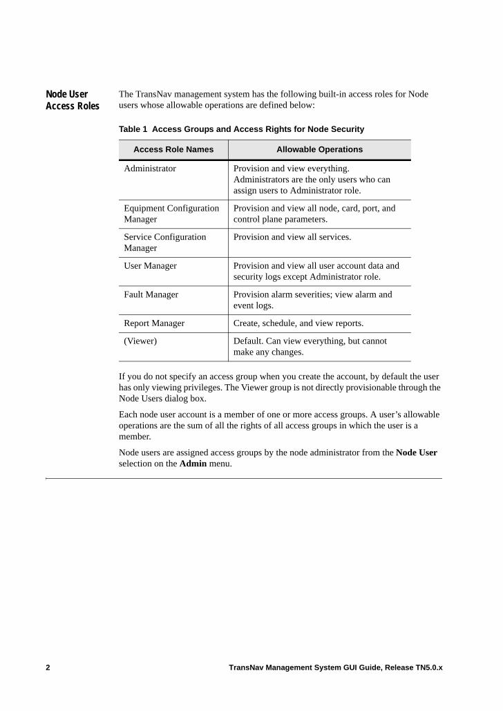
Node User Access Roles
The TransNav management system has the following built-in access roles for Node users whose allowable operations are defined below:
If you do not specify an access group when you create the account, by default the user has only viewing privileges. The Viewer group is not directly provisionable through the Node Users dialog box.
Each node user account is a member of one or more access groups. A user’s allowable operations are the sum of all the rights of all access groups in which the user is a member.
Node users are assigned access groups by the node administrator from the Node User selection on the Admin menu.
Table 1 Access Groups and Access Rights for Node Security
Access Role Names Allowable Operations
Administrator Provision and view everything. Administrators are the only users who can assign users to Administrator role.
Equipment Configuration Manager
Provision and view all node, card, port, and control plane parameters.
Service Configuration Manager
Provision and view all services.
User Manager Provision and view all user account data and security logs except Administrator role.
Fault Manager Provision alarm severities; view alarm and event logs.
Report Manager Create, schedule, and view reports.
(Viewer) Default. Can view everything, but cannot make any changes.
2 TransNav Management System GUI Guide, Release TN5.0.x
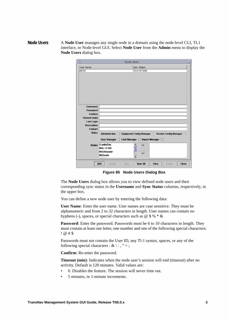
Node Users A Node User manages any single node in a domain using the node-level CLI, TL1 interface, or Node-level GUI. Select Node User from the Admin menu to display the Node Users dialog box.
Figure 85 Node Users Dialog Box
The Node Users dialog box allows you to view defined node users and their corresponding sync status in the Username and Sync Status columns, respectively, in the upper box.
You can define a new node user by entering the following data:
User Name: Enter the user name. User names are case sensitive. They must be alphanumeric and from 2 to 32 characters in length. User names can contain no hyphens (-), spaces, or special characters such as @ $ % * &
Password: Enter the password. Passwords must be 6 to 10 characters in length. They must contain at least one letter, one number and one of the following special characters: ! @ # $
Passwords must not contain the User ID, any Tl-1 syntax, spaces, or any of the following special characters : & \ : , “ = ;
Confirm: Re-enter the password.
Timeout (min): Indicates when the node user’s session will end (timeout) after no activity. Default is 120 minutes. Valid values are:• 0. Disables the feature. The session will never time out. • 5 minutes, in 1-minute increments.
TransNav Management System GUI Guide, Release TN5.0.x 3
A warning message appears two minutes before the session times out. A Session Terminated dialog box displays when the session times out. User preferences are not saved when a session times out.
Last Login: Indicates the last time and location the user logged into the system through the node TL1, node CLI, or the node-level GUI on a Traverse node. If a user is not logged in, the value is blank. This feature is not available for TE-100 or TE-206 node users.
Note: This information will only appear if the node software version matches the server software version. This parameter remains blank for users on nodes using a software version that does not match the server software version.
Description: Enter detail information about the node user. Maximum length is 100 characters. Default is blank. This feature is not available for TE-100 or TE-206 node users.
Contact: Enter contact information for the node user. Maximum length is 100 characters. Default is blank. This feature is not available for TE-100 or TE-206 node users.
Roles: Select one or more access roles from the list and click the right arrow to assign the role to the user:• Administrator• Equipment Config Manager• Service Config Manager• User Manager• Fault Manager• Report Manager
Nodes: Select a node from the list of nodes in the domain and click the right arrow to allow the user to manage that node.
Command buttons are as follows:• Add: Add the node user to the Username list.• Update: Update the changes for the selected node user.• Sync: Synchronize all node users. For additional information on synchronization,
see Chapter 1—“General Description of GUI Features TN5.0.x,” Scroll Bars. • Sync All: Synchronize all node users, allowing all node users access to any of the
nodes in the domain. • Clear: Clear all information that has not been saved.• Delete: Select a Username and click Delete to remove the selected node user.• Close: Save the changes and close the dialog box.
Important: For security reasons, Force10 recommends using the value “0” with extreme caution.
4 TransNav Management System GUI Guide, Release TN5.0.x
Chapter 6 Using TransNav GUI with TN-Sight
Introduction (SONET network only) This chapter describes using the TransNav management system graphical user interface (GUI) in conjunction with the TransNav Sight (TN-Sight) web craft GUI to discover and manage Traverse, TE-100, and TE-206 nodes from a single server.
TransNav can be used to manage TE-206 nodes as either standalone nodes or in a network ring.
The following topics are covered in this chapter:• Prerequisites• Access Roles on TN-Sight• Provisioning TE-206 Nodes from TransNav• TE-206 Alarms and Events• TE-206 Node Database Backup and Restore• Removing TE-206 Nodes
Prerequisites The initial set up of TE-206 nodes must be completed prior to being discovered by the network and displaying on the TransNav GUI. For more information, see the following:• TraverseEdge 206 Hardware Installation Guide. Contains information on setting up
the TE-206 hardware. • TraverseEdge 206 Users Guide. For information on using the TE-206. • Chapter 1—“General Description of GUI Features TN5.0.x,” Managing TE-206
Nodes from TransNav. For information on required port settings for Traverse, TE-206, and TE-100 nodes.
• For information on discovering the TE-206 on TransNav, see the TransNav Management System Provisioning Guide, Chapter 7—“Network Auto Discovery,”
When DCC links are added or removed from the network, they must be rediscovered by the network using a manual procedure. From the TransNav GUI, select Admin, then select Rediscover. The rediscovery process takes a few minutes to complete. During this time, the links will appear to be unchanged.
TransNav Management System GUI Guide, Release TN5.0.x 1
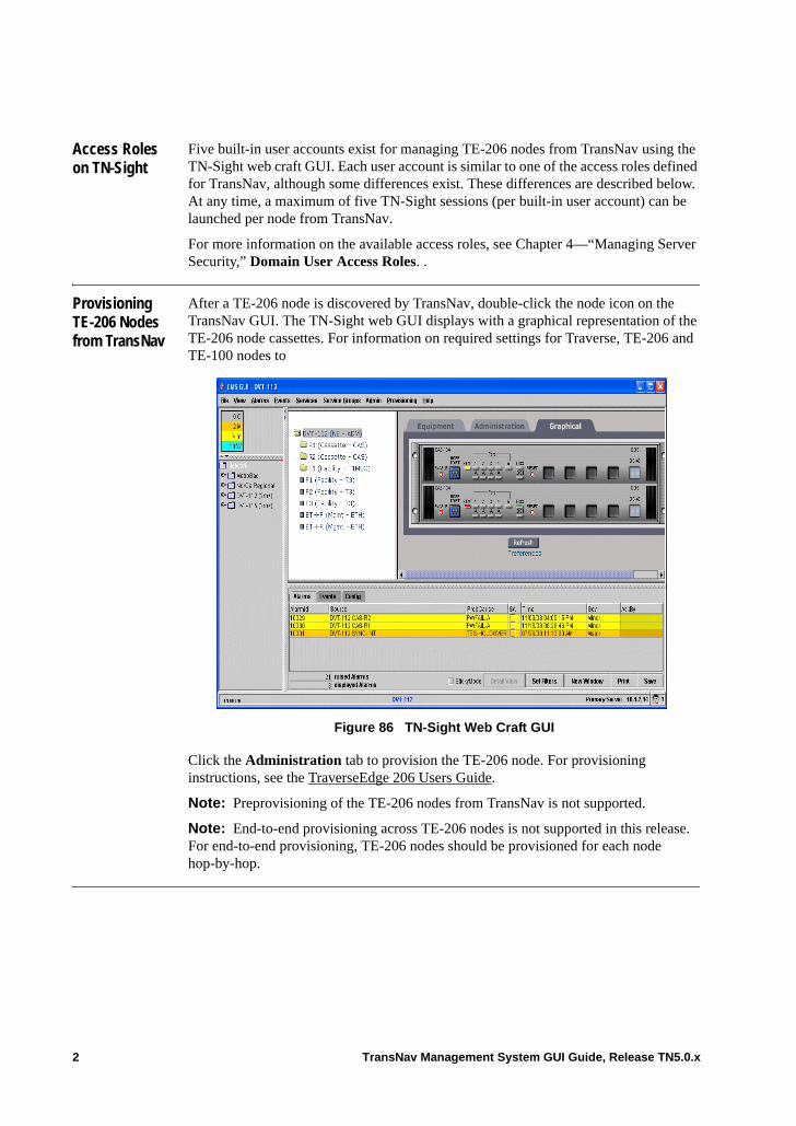
Access Roles on TN-Sight
Five built-in user accounts exist for managing TE-206 nodes from TransNav using the TN-Sight web craft GUI. Each user account is similar to one of the access roles defined for TransNav, although some differences exist. These differences are described below. At any time, a maximum of five TN-Sight sessions (per built-in user account) can be launched per node from TransNav.
For more information on the available access roles, see Chapter 4—“Managing Server Security,” Domain User Access Roles. .
Provisioning TE-206 Nodes from TransNav
After a TE-206 node is discovered by TransNav, double-click the node icon on the TransNav GUI. The TN-Sight web GUI displays with a graphical representation of the TE-206 node cassettes. For information on required settings for Traverse, TE-206 and TE-100 nodes to
Figure 86 TN-Sight Web Craft GUI
Click the Administration tab to provision the TE-206 node. For provisioning instructions, see the TraverseEdge 206 Users Guide.
Note: Preprovisioning of the TE-206 nodes from TransNav is not supported.
Note: End-to-end provisioning across TE-206 nodes is not supported in this release. For end-to-end provisioning, TE-206 nodes should be provisioned for each node hop-by-hop.
2 TransNav Management System GUI Guide, Release TN5.0.x
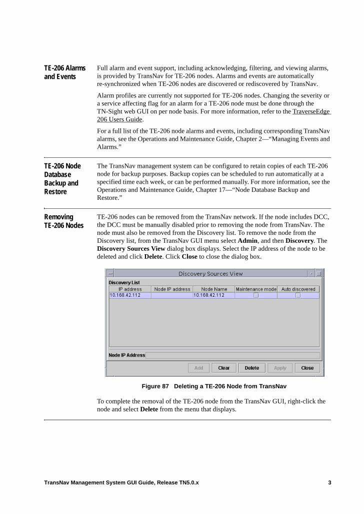
TE-206 Alarms and Events
Full alarm and event support, including acknowledging, filtering, and viewing alarms, is provided by TransNav for TE-206 nodes. Alarms and events are automatically re-synchronized when TE-206 nodes are discovered or rediscovered by TransNav.
Alarm profiles are currently not supported for TE-206 nodes. Changing the severity or a service affecting flag for an alarm for a TE-206 node must be done through the TN-Sight web GUI on per node basis. For more information, refer to the TraverseEdge 206 Users Guide.
For a full list of the TE-206 node alarms and events, including corresponding TransNav alarms, see the Operations and Maintenance Guide, Chapter 2—“Managing Events and Alarms.”
TE-206 Node Database Backup and Restore
The TransNav management system can be configured to retain copies of each TE-206 node for backup purposes. Backup copies can be scheduled to run automatically at a specified time each week, or can be performed manually. For more information, see the Operations and Maintenance Guide, Chapter 17—“Node Database Backup and Restore.”
Removing TE-206 Nodes
TE-206 nodes can be removed from the TransNav network. If the node includes DCC, the DCC must be manually disabled prior to removing the node from TransNav. The node must also be removed from the Discovery list. To remove the node from the Discovery list, from the TransNav GUI menu select Admin, and then Discovery. The Discovery Sources View dialog box displays. Select the IP address of the node to be deleted and click Delete. Click Close to close the dialog box.
Figure 87 Deleting a TE-206 Node from TransNav
To complete the removal of the TE-206 node from the TransNav GUI, right-click the node and select Delete from the menu that displays.
TransNav Management System GUI Guide, Release TN5.0.x 3

4 TransNav Management System GUI Guide, Release TN5.0.x
Chapter 7 Managing TE-206 Nodes from TransNav
Introduction This chapter describes how to manage TraverseEdge 206 nodes from the TransNav graphical user interface (GUI).
Using the EMS GUI, you can view the network or domains you are managing (Map View) or any particular shelf (Shelf View). Context-sensitive tabs are available for the view selected.
The Map View displays all the nodes in a network and is the initial display when you start the GUI.
The Traverse Shelf View displays all the cards (modules) in a node and their associated ports.
The TE-100 Shelf View displays the shelf view for the TE-100.
For information on these features, see Chapter 1—“General Description of GUI Features TN5.0.x.”
This chapter describes the following GUI features:• Managing TE-206 Nodes from TransNav• Discovering TE-206 Nodes from TransNav
TransNav Management System GUI Guide, Release TN5.0.x 1
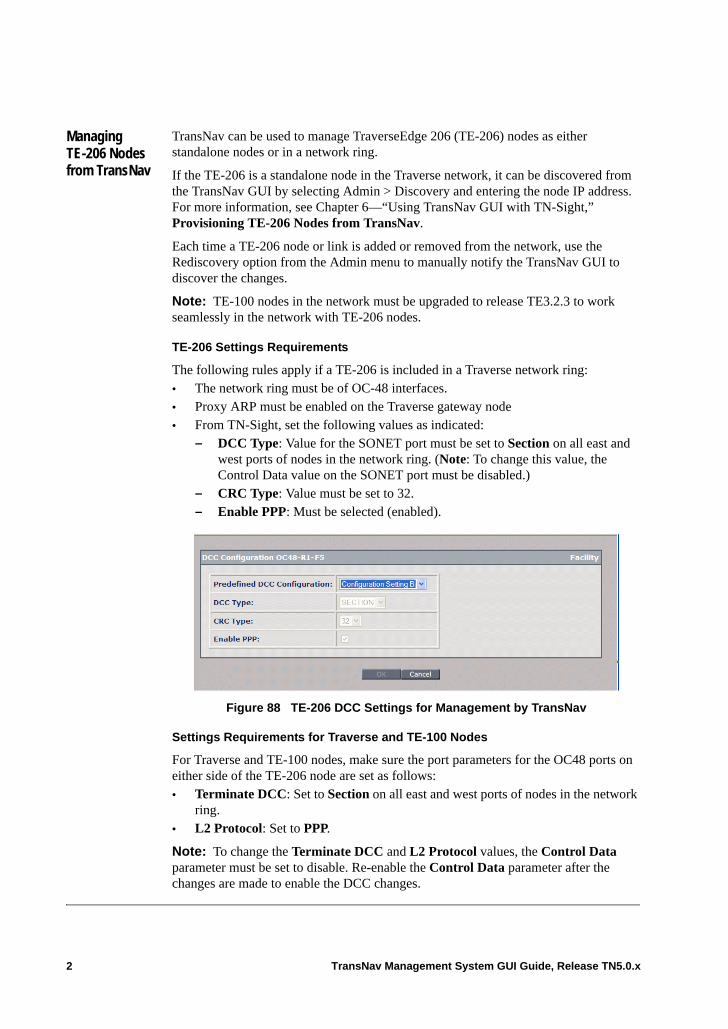
Managing TE-206 Nodes from TransNav
TransNav can be used to manage TraverseEdge 206 (TE-206) nodes as either standalone nodes or in a network ring.
If the TE-206 is a standalone node in the Traverse network, it can be discovered from the TransNav GUI by selecting Admin > Discovery and entering the node IP address. For more information, see Chapter 6—“Using TransNav GUI with TN-Sight,” Provisioning TE-206 Nodes from TransNav.
Each time a TE-206 node or link is added or removed from the network, use the Rediscovery option from the Admin menu to manually notify the TransNav GUI to discover the changes.
Note: TE-100 nodes in the network must be upgraded to release TE3.2.3 to work seamlessly in the network with TE-206 nodes.
TE-206 Settings Requirements
The following rules apply if a TE-206 is included in a Traverse network ring: • The network ring must be of OC-48 interfaces. • Proxy ARP must be enabled on the Traverse gateway node• From TN-Sight, set the following values as indicated:
– DCC Type: Value for the SONET port must be set to Section on all east and west ports of nodes in the network ring. (Note: To change this value, the Control Data value on the SONET port must be disabled.)
– CRC Type: Value must be set to 32.– Enable PPP: Must be selected (enabled).
Figure 88 TE-206 DCC Settings for Management by TransNav
Settings Requirements for Traverse and TE-100 Nodes
For Traverse and TE-100 nodes, make sure the port parameters for the OC48 ports on either side of the TE-206 node are set as follows: • Terminate DCC: Set to Section on all east and west ports of nodes in the network
ring. • L2 Protocol: Set to PPP.
Note: To change the Terminate DCC and L2 Protocol values, the Control Data parameter must be set to disable. Re-enable the Control Data parameter after the changes are made to enable the DCC changes.
2 TransNav Management System GUI Guide, Release TN5.0.x
Discovering TE-206 Nodes from TransNav
For TE-206 nodes, only link information for adjacent TE-206 nodes is required to detect and provide TE-206 connectivity information to TransNav. A point-to-point protocol is used to discover links between Traverse nodes and TE-206 nodes. This protocol is enabled by default on OC-48 ports on Traverse nodes to allow link information to be exchanged between Traverse and TE-206 nodes. The point-to-point protocol is not supported on TE-206 nodes for OC-3 or OC-12 ports.
Note: From the TransNav GUI, select the Admin menu to access the Rediscovery option. Use this option when a TE-206 node or link is added or removed to manually notify TransNav to discover the changes.
Command buttons are as follows:• Add: Add the node-ip in the Node IP Address field to the Discovery List.• Clear: Clear the entry in the Node IP Address field.• Delete: Delete the Node IP Address selected in the Discovery List.• Apply: Apply the changes made in the Maintenance mode column.• Done: Close the Discovery Sources View dialog box.
TransNav Management System GUI Guide, Release TN5.0.x 3

4 TransNav Management System GUI Guide, Release TN5.0.x
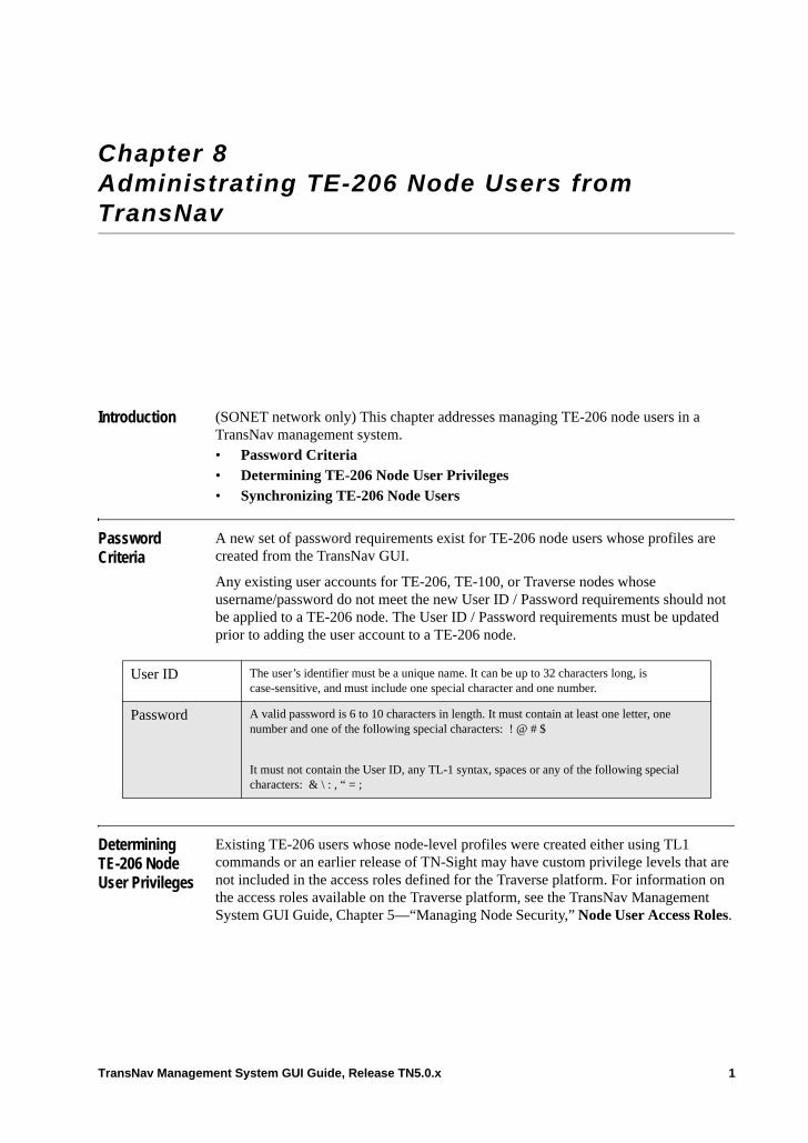
Chapter 8 Administrating TE-206 Node Users from TransNav
Introduction (SONET network only) This chapter addresses managing TE-206 node users in a TransNav management system. • Password Criteria• Determining TE-206 Node User Privileges• Synchronizing TE-206 Node Users
Password Criteria
A new set of password requirements exist for TE-206 node users whose profiles are created from the TransNav GUI.
Any existing user accounts for TE-206, TE-100, or Traverse nodes whose username/password do not meet the new User ID / Password requirements should not be applied to a TE-206 node. The User ID / Password requirements must be updated prior to adding the user account to a TE-206 node.
Determining TE-206 Node User Privileges
Existing TE-206 users whose node-level profiles were created either using TL1 commands or an earlier release of TN-Sight may have custom privilege levels that are not included in the access roles defined for the Traverse platform. For information on the access roles available on the Traverse platform, see the TransNav Management System GUI Guide, Chapter 5—“Managing Node Security,” Node User Access Roles.
User ID The user’s identifier must be a unique name. It can be up to 32 characters long, is case-sensitive, and must include one special character and one number.
Password A valid password is 6 to 10 characters in length. It must contain at least one letter, one number and one of the following special characters: ! @ # $
It must not contain the User ID, any TL-1 syntax, spaces or any of the following special characters: & \ : , “ = ;
TransNav Management System GUI Guide, Release TN5.0.x 1
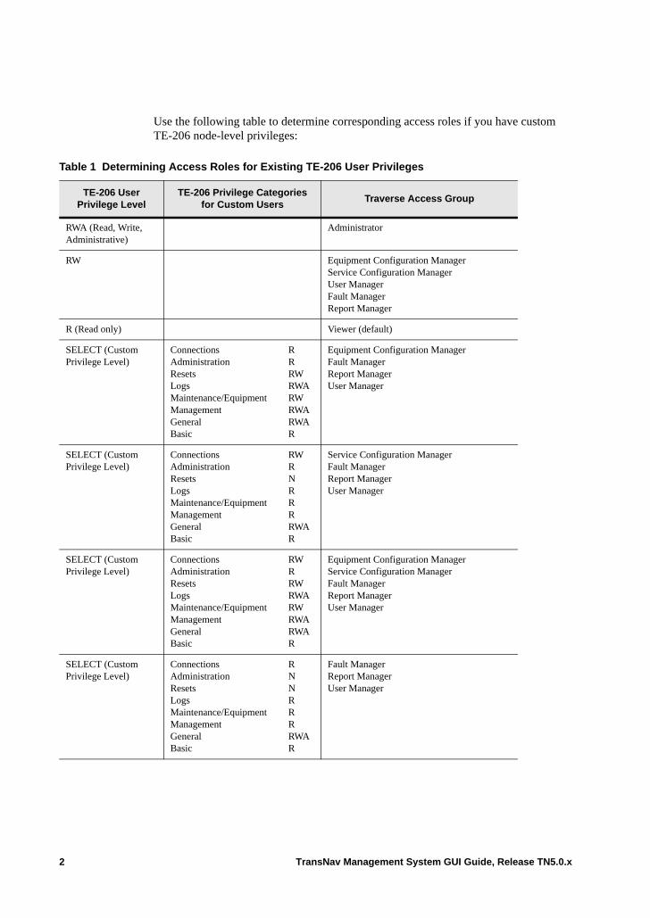
Use the following table to determine corresponding access roles if you have custom TE-206 node-level privileges:
Table 1 Determining Access Roles for Existing TE-206 User Privileges
TE-206 User Privilege Level
TE-206 Privilege Categories for Custom Users
Traverse Access Group
RWA (Read, Write, Administrative)
Administrator
RW Equipment Configuration ManagerService Configuration ManagerUser ManagerFault ManagerReport Manager
R (Read only) Viewer (default)
SELECT (Custom Privilege Level)
ConnectionsAdministrationResetsLogsMaintenance/EquipmentManagementGeneralBasic
RRRWRWARWRWARWAR
Equipment Configuration ManagerFault ManagerReport ManagerUser Manager
SELECT (Custom Privilege Level)
ConnectionsAdministrationResetsLogsMaintenance/EquipmentManagementGeneralBasic
RWRNRRRRWAR
Service Configuration ManagerFault ManagerReport ManagerUser Manager
SELECT (Custom Privilege Level)
ConnectionsAdministrationResetsLogsMaintenance/EquipmentManagementGeneralBasic
RWRRWRWARWRWARWAR
Equipment Configuration ManagerService Configuration ManagerFault ManagerReport ManagerUser Manager
SELECT (Custom Privilege Level)
ConnectionsAdministrationResetsLogsMaintenance/EquipmentManagementGeneralBasic
RNNRRRRWAR
Fault ManagerReport ManagerUser Manager
2 TransNav Management System GUI Guide, Release TN5.0.x
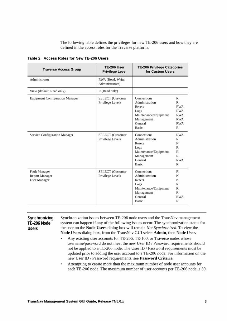
The following table defines the privileges for new TE-206 users and how they are defined in the access roles for the Traverse platform.
Synchronizing TE-206 Node Users
Synchronization issues between TE-206 node users and the TransNav management system can happen if any of the following issues occur. The synchronization status for the user on the Node Users dialog box will remain Not Synchronized. To view the Node Users dialog box, from the TransNav GUI select Admin, then Node User. • Any existing user accounts for TE-206, TE-100, or Traverse nodes whose
username/password do not meet the new User ID / Password requirements should not be applied to a TE-206 node. The User ID / Password requirements must be updated prior to adding the user account to a TE-206 node. For information on the new User ID / Password requirements, see Password Criteria.
• Attempting to create more than the maximum number of node user accounts for each TE-206 node. The maximum number of user accounts per TE-206 node is 50.
Table 2 Access Roles for New TE-206 Users
Traverse Access GroupTE-206 User
Privilege LevelTE-206 Privilege Categories
for Custom Users
Administrator RWA (Read, Write, Administrative)
View (default, Read only) R (Read only)
Equipment Configuration Manager SELECT (Customer Privilege Level)
ConnectionsAdministrationResetsLogsMaintenance/EquipmentManagementGeneralBasic
RRRWARWARWARWARWAR
Service Configuration Manager SELECT (Customer Privilege Level)
ConnectionsAdministrationResetsLogsMaintenance/EquipmentManagementGeneralBasic
RWARNRRRRWAR
Fault ManagerReport ManagerUser Manager
SELECT (Customer Privilege Level)
ConnectionsAdministrationResetsLogsMaintenance/EquipmentManagementGeneralBasic
RNNRRRRWAR
TransNav Management System GUI Guide, Release TN5.0.x 3
• If a new user account for a TE-206 node is detected when a new TE-206 is discovered, the user must reset their password the first time they log on to allow TransNav to verify the password. If the password is not reset, synchronization issues occur.
4 TransNav Management System GUI Guide, Release TN5.0.x
Chapter 9 TransNav User Preferences
Introduction This chapter describes the following TransNav server GUI features:• Select Background Image for Map View• Saving and Importing User Preferences• Customize System Options• Grouping Nodes• Changing Node Group Names
TransNav Management System GUI Guide, Release TN5.0.x 1
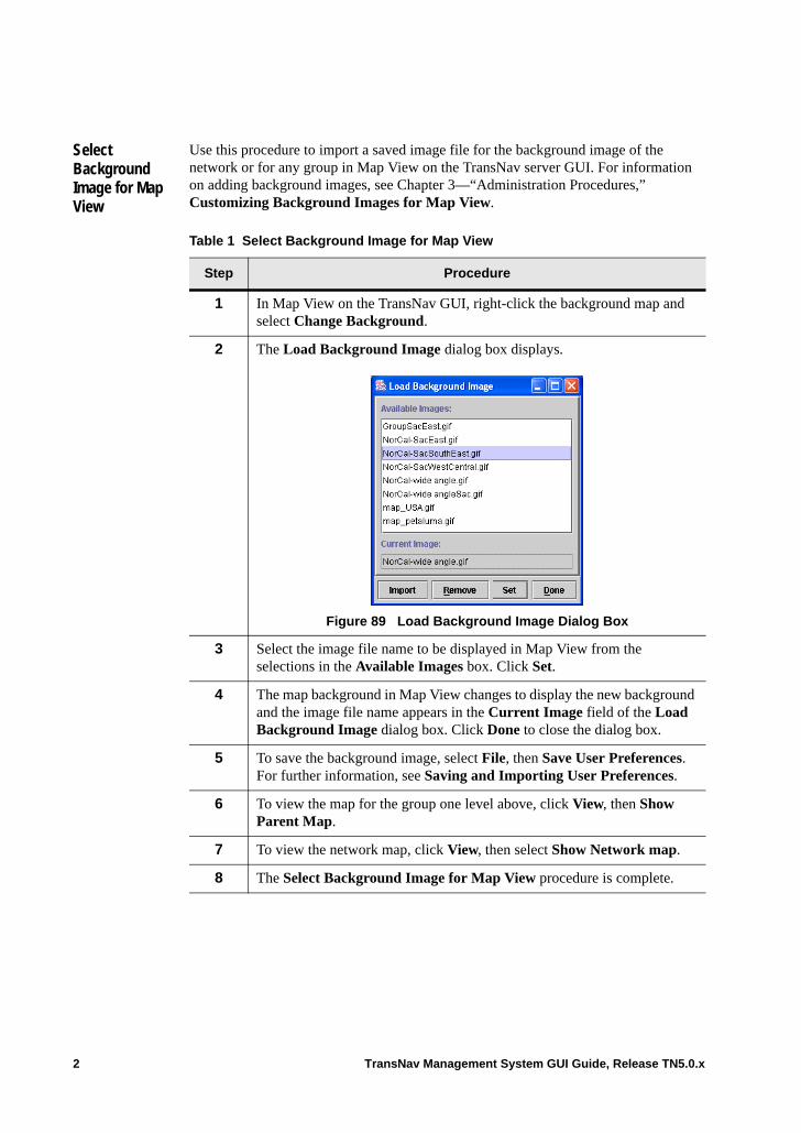
Select Background Image for Map View
Use this procedure to import a saved image file for the background image of the network or for any group in Map View on the TransNav server GUI. For information on adding background images, see Chapter 3—“Administration Procedures,” Customizing Background Images for Map View.
Table 1 Select Background Image for Map View
Step Procedure
1 In Map View on the TransNav GUI, right-click the background map and select Change Background.
2 The Load Background Image dialog box displays.
Figure 89 Load Background Image Dialog Box
3 Select the image file name to be displayed in Map View from the selections in the Available Images box. Click Set.
4 The map background in Map View changes to display the new background and the image file name appears in the Current Image field of the Load Background Image dialog box. Click Done to close the dialog box.
5 To save the background image, select File, then Save User Preferences. For further information, see Saving and Importing User Preferences.
6 To view the map for the group one level above, click View, then Show Parent Map.
7 To view the network map, click View, then select Show Network map.
8 The Select Background Image for Map View procedure is complete.
2 TransNav Management System GUI Guide, Release TN5.0.x
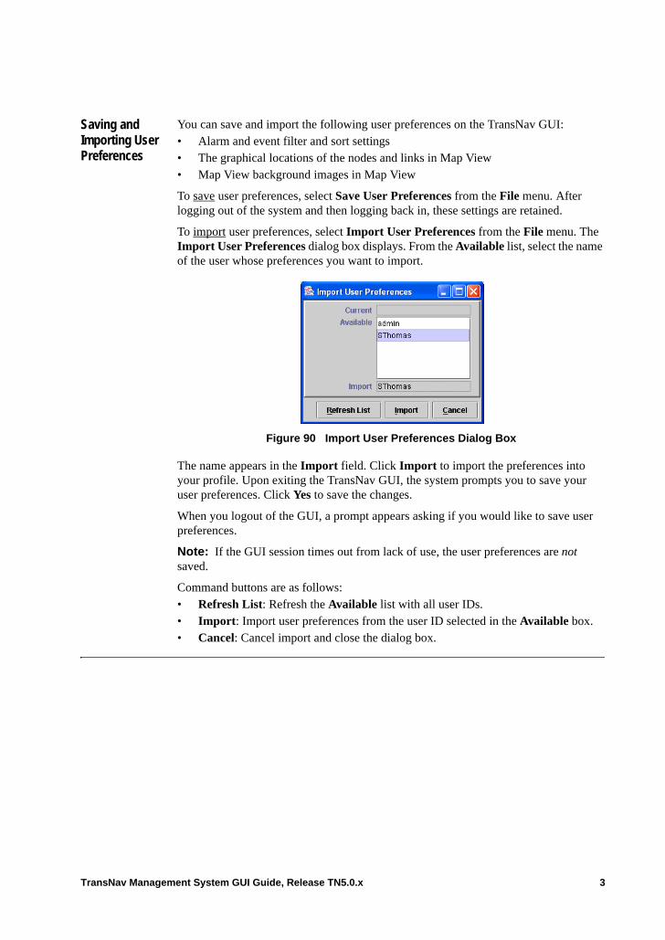
Saving and Importing User Preferences
You can save and import the following user preferences on the TransNav GUI:• Alarm and event filter and sort settings• The graphical locations of the nodes and links in Map View• Map View background images in Map View
To save user preferences, select Save User Preferences from the File menu. After logging out of the system and then logging back in, these settings are retained.
To import user preferences, select Import User Preferences from the File menu. The Import User Preferences dialog box displays. From the Available list, select the name of the user whose preferences you want to import.
Figure 90 Import User Preferences Dialog Box
The name appears in the Import field. Click Import to import the preferences into your profile. Upon exiting the TransNav GUI, the system prompts you to save your user preferences. Click Yes to save the changes.
When you logout of the GUI, a prompt appears asking if you would like to save user preferences.
Note: If the GUI session times out from lack of use, the user preferences are not saved.
Command buttons are as follows:• Refresh List: Refresh the Available list with all user IDs.• Import: Import user preferences from the user ID selected in the Available box.• Cancel: Cancel import and close the dialog box.
TransNav Management System GUI Guide, Release TN5.0.x 3
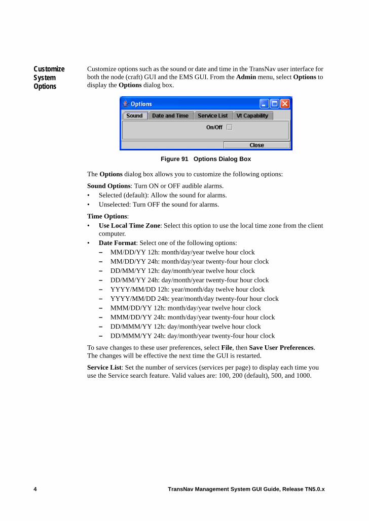
Customize System Options
Customize options such as the sound or date and time in the TransNav user interface for both the node (craft) GUI and the EMS GUI. From the Admin menu, select Options to display the Options dialog box.
Figure 91 Options Dialog Box
The Options dialog box allows you to customize the following options:
Sound Options: Turn ON or OFF audible alarms.• Selected (default): Allow the sound for alarms.• Unselected: Turn OFF the sound for alarms.
Time Options: • Use Local Time Zone: Select this option to use the local time zone from the client
computer.• Date Format: Select one of the following options:
– MM/DD/YY 12h: month/day/year twelve hour clock– MM/DD/YY 24h: month/day/year twenty-four hour clock– DD/MM/YY 12h: day/month/year twelve hour clock– DD/MM/YY 24h: day/month/year twenty-four hour clock– YYYY/MM/DD 12h: year/month/day twelve hour clock– YYYY/MM/DD 24h: year/month/day twenty-four hour clock– MMM/DD/YY 12h: month/day/year twelve hour clock– MMM/DD/YY 24h: month/day/year twenty-four hour clock– DD/MMM/YY 12h: day/month/year twelve hour clock– DD/MMM/YY 24h: day/month/year twenty-four hour clock
To save changes to these user preferences, select File, then Save User Preferences. The changes will be effective the next time the GUI is restarted.
Service List: Set the number of services (services per page) to display each time you use the Service search feature. Valid values are: 100, 200 (default), 500, and 1000.
4 TransNav Management System GUI Guide, Release TN5.0.x
VT Capability: Select this option to show VT/VC switching capability on the map. Each VT capable node will include a box with the letters “L” and “O” indicating low-order capability as shown.
Note: Depending on the size of your network and number of current users, a slight delay may occur when using this feature.
Command buttons are as follows:
Close: Close the dialog box and return to the main menu.
TransNav Management System GUI Guide, Release TN5.0.x 5
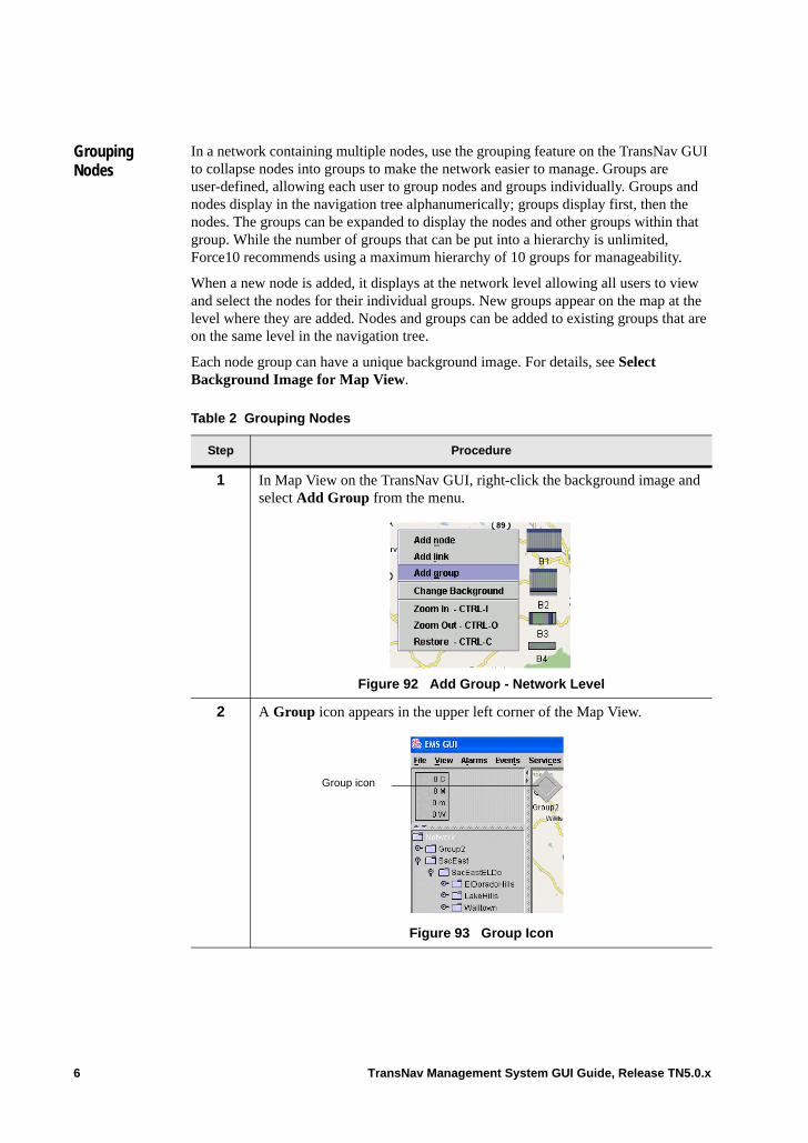
Grouping Nodes
In a network containing multiple nodes, use the grouping feature on the TransNav GUI to collapse nodes into groups to make the network easier to manage. Groups are user-defined, allowing each user to group nodes and groups individually. Groups and nodes display in the navigation tree alphanumerically; groups display first, then the nodes. The groups can be expanded to display the nodes and other groups within that group. While the number of groups that can be put into a hierarchy is unlimited, Force10 recommends using a maximum hierarchy of 10 groups for manageability.
When a new node is added, it displays at the network level allowing all users to view and select the nodes for their individual groups. New groups appear on the map at the level where they are added. Nodes and groups can be added to existing groups that are on the same level in the navigation tree.
Each node group can have a unique background image. For details, see Select Background Image for Map View.
Table 2 Grouping Nodes
Step Procedure
1 In Map View on the TransNav GUI, right-click the background image and select Add Group from the menu.
Figure 92 Add Group - Network Level
2 A Group icon appears in the upper left corner of the Map View.
Figure 93 Group Icon
Group icon
6 TransNav Management System GUI Guide, Release TN5.0.x
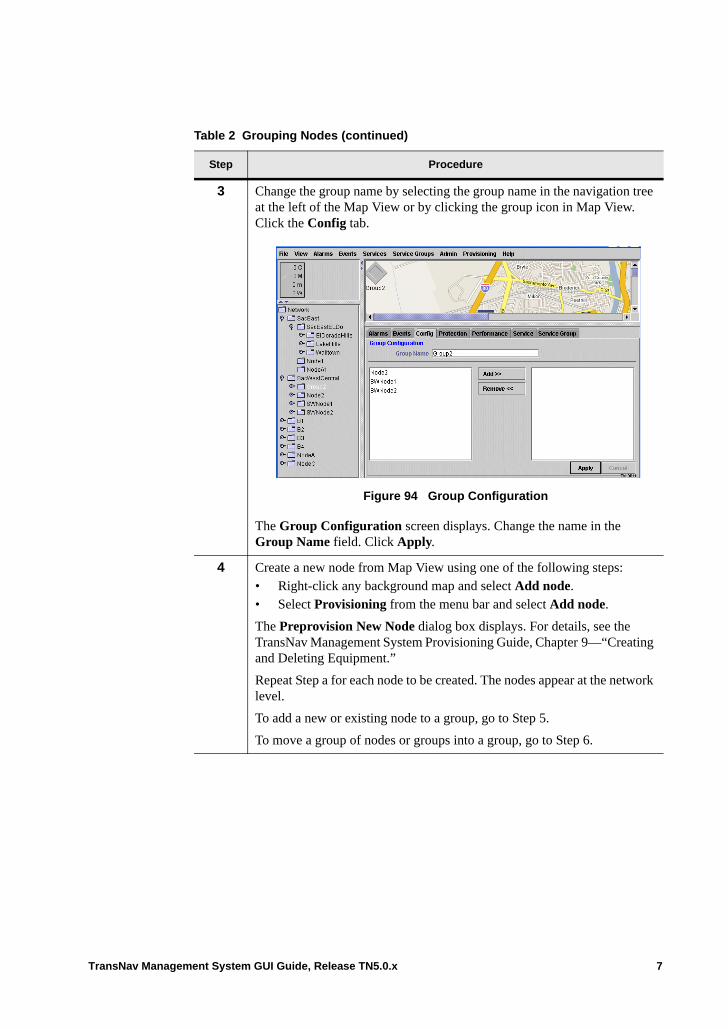
3 Change the group name by selecting the group name in the navigation tree at the left of the Map View or by clicking the group icon in Map View. Click the Config tab.
Figure 94 Group Configuration
The Group Configuration screen displays. Change the name in the Group Name field. Click Apply.
4 Create a new node from Map View using one of the following steps:• Right-click any background map and select Add node.• Select Provisioning from the menu bar and select Add node.
The Preprovision New Node dialog box displays. For details, see the TransNav Management System Provisioning Guide, Chapter 9—“Creating and Deleting Equipment.”
Repeat Step a for each node to be created. The nodes appear at the network level.
To add a new or existing node to a group, go to Step 5.
To move a group of nodes or groups into a group, go to Step 6.
Table 2 Grouping Nodes (continued)
Step Procedure
TransNav Management System GUI Guide, Release TN5.0.x 7
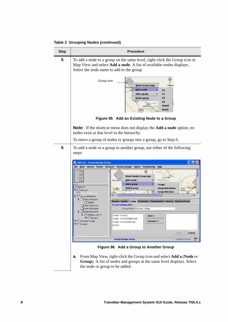
5 To add a node to a group on the same level, right-click the Group icon in Map View and select Add a node. A list of available nodes displays. Select the node name to add to the group.
Figure 95 Add an Existing Node to a Group
Note: If the shortcut menu does not display the Add a node option, no nodes exist at that level in the hierarchy.
To move a group of nodes or groups into a group, go to Step 6.
6 To add a node or a group to another group, use either of the following steps:
Figure 96 Add a Group to Another Group
a. From Map View, right-click the Group icon and select Add a (Node or Group). A list of nodes and groups at the same level displays. Select the node or group to be added.
Table 2 Grouping Nodes (continued)
Step Procedure
Group icon
8 TransNav Management System GUI Guide, Release TN5.0.x
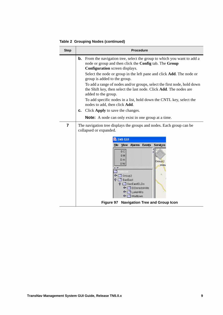
b. From the navigation tree, select the group to which you want to add a node or group and then click the Config tab. The Group Configuration screen displays.Select the node or group in the left pane and click Add. The node or group is added to the group. To add a range of nodes and/or groups, select the first node, hold down the Shift key, then select the last node. Click Add. The nodes are added to the group.To add specific nodes in a list, hold down the CNTL key, select the nodes to add, then click Add.
c. Click Apply to save the changes.
Note: A node can only exist in one group at a time.
7 The navigation tree displays the groups and nodes. Each group can be collapsed or expanded.
Figure 97 Navigation Tree and Group Icon
Table 2 Grouping Nodes (continued)
Step Procedure
TransNav Management System GUI Guide, Release TN5.0.x 9
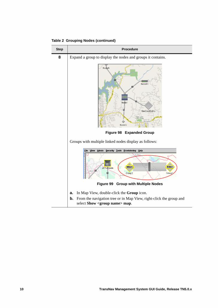
8 Expand a group to display the nodes and groups it contains.
Figure 98 Expanded Group
Groups with multiple linked nodes display as follows:
Figure 99 Group with Multiple Nodes
a. In Map View, double-click the Group icon.
b. From the navigation tree or in Map View, right-click the group and select Show <group name> map.
Table 2 Grouping Nodes (continued)
Step Procedure
10 TransNav Management System GUI Guide, Release TN5.0.x
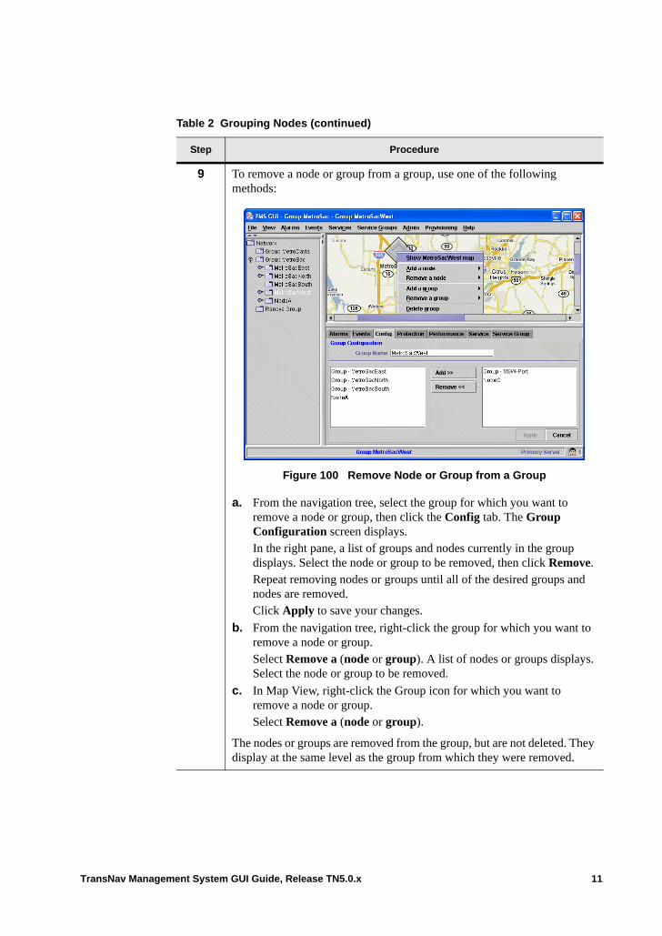
9 To remove a node or group from a group, use one of the following methods:
Figure 100 Remove Node or Group from a Group
a. From the navigation tree, select the group for which you want to remove a node or group, then click the Config tab. The Group Configuration screen displays.In the right pane, a list of groups and nodes currently in the group displays. Select the node or group to be removed, then click Remove. Repeat removing nodes or groups until all of the desired groups and nodes are removed.Click Apply to save your changes.
b. From the navigation tree, right-click the group for which you want to remove a node or group. Select Remove a (node or group). A list of nodes or groups displays. Select the node or group to be removed.
c. In Map View, right-click the Group icon for which you want to remove a node or group.Select Remove a (node or group).
The nodes or groups are removed from the group, but are not deleted. They display at the same level as the group from which they were removed.
Table 2 Grouping Nodes (continued)
Step Procedure
TransNav Management System GUI Guide, Release TN5.0.x 11
10 To delete a group and all nodes and groups attached to it, use one of the following steps:
a. From the navigation tree, right-click the group to delete, then select Delete group.
b. From Map View, right-click the group to delete. Select Delete group.
A confirmation message displays. Click Yes to continue the deletion.
11 From the File menu, click Save User Preferences to save the grouping.
12 The Grouping Nodes procedure is complete.
Table 2 Grouping Nodes (continued)
Step Procedure
12 TransNav Management System GUI Guide, Release TN5.0.x
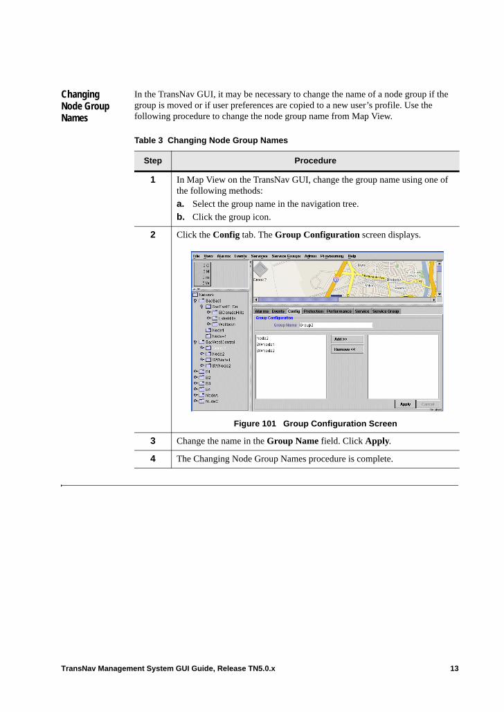
Changing Node Group Names
In the TransNav GUI, it may be necessary to change the name of a node group if the group is moved or if user preferences are copied to a new user’s profile. Use the following procedure to change the node group name from Map View.
Table 3 Changing Node Group Names
Step Procedure
1 In Map View on the TransNav GUI, change the group name using one of the following methods:
a. Select the group name in the navigation tree.
b. Click the group icon.
2 Click the Config tab. The Group Configuration screen displays.
Figure 101 Group Configuration Screen
3 Change the name in the Group Name field. Click Apply.
4 The Changing Node Group Names procedure is complete.
TransNav Management System GUI Guide, Release TN5.0.x 13

14 TransNav Management System GUI Guide, Release TN5.0.x
Chapter 10 Generating and Viewing Reports
Introduction This chapter includes the following topics that describe the steps to generate reports, create report templates, then view and remove reports using the Admin menu on the TransNav management system server GUI.
Note: These functions are not available from the Node-level GUI.
• Generating Reports• Generating a PM Report• Using the Report Scheduler• Adding Customer Information • Viewing Reports• Example Report Output• Removing Generated Reports
Generating Reports
Through the TransNav management system, you have the ability to create different reports. You can customize the reports for your own uses, as well as specify generation dates and generation periods.
To monitor performance on any resource, know how to create, modify, and use the performance monitoring templates. For more information, see the Operations and Maintenance Guide, Chapter 4—“Managing Performance.”
Generate a set of data in a particular format at specified intervals. The following report types can be generated for all nodes in the domain or for a specific node:• Historical alarm• Node inventory• Historical event• Performance monitoring• Resource availability• Domain service• Service availability
Additionally, capacity monitoring of switching capacity on VT/TU cards is available to assist in planning resource usage on these cards.
Note: If you have multiple servers set up in your Traverse system and want long-term access to configuration statistics for all of the servers, Force10 recommends performing regular backups of the configuration files on each server. (Alarm and event data is not
TransNav Management System GUI Guide, Release TN5.0.x 1
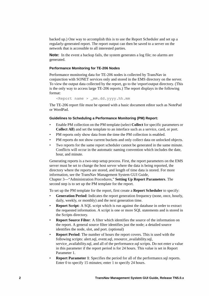
backed up.) One way to accomplish this is to use the Report Scheduler and set up a regularly-generated report. The report output can then be saved to a server on the network that is accessible to all interested parties.
Note: In the event a backup fails, the system generates a log file; no alarms are generated.
Performance Monitoring for TE-206 Nodes
Performance monitoring data for TE-206 nodes is collected by TransNav in conjunction with SONET services only and stored in the EMS directory on the server. To view the output data collected by the report, go to the \report\output directory. (This is the only way to access large TE-206 reports.) The report displays in the following format:
<Report name > _mm.dd.yyyy.hh.mm
The TE-206 report file must be opened with a basic document editor such as NotePad or WordPad.
Guidelines to Scheduling a Performance Monitoring (PM) Report:
• Enable PM collection on the PM template (select Collect for specific parameters or Collect All) and set the template to an interface such as a service, card, or port.
• PM reports only show data from the time the PM collection is enabled. • PM reports do not show current buckets and only collect data on unlocked objects. • Two reports for the same report scheduler cannot be generated in the same minute.
Conflicts will occur in the automatic naming convention which includes the date, hour, and minute.
Generating reports is a two-step setup process. First, the report parameters on the EMS server must be set to change the host server where the data is being reported, the directory where the reports are stored, and length of time data is stored. For more information, see the TransNav Management System GUI Guide, Chapter 3—“Administration Procedures,” Setting Up Report Parameters. The second step is to set up the PM template for the report.
To set up the PM template for the report, first create a Report Scheduler to specify:• Generation Period: Indicates the report generation frequency (none, once, hourly,
daily, weekly, or monthly) and the next generation time.• Report Script: A SQL script which is run against the database in order to extract
the requested information. A script is one or more SQL statements and is stored in the Scripts directory.
• Report Source Filter: A filter which identifies the source of the information on the report. A general source filter identifies just the node; a detailed source identifies the node, slot, and port. (optional)
• Report Period: The number of hours the report covers. This is used with the following scripts: alert.sql, event.sql, resource_availability.sql, service_availability.sql, and all of the performance.sql scripts. Do not enter a value in this parameter if the report period is for 24 hours. This value is set in Report Parameter 1.
• Report Parameter 1: Specifies the period for all of the performance.sql reports. Enter 0 to specify 15 minutes; enter 1 to specify 24 hours.
2 TransNav Management System GUI Guide, Release TN5.0.x
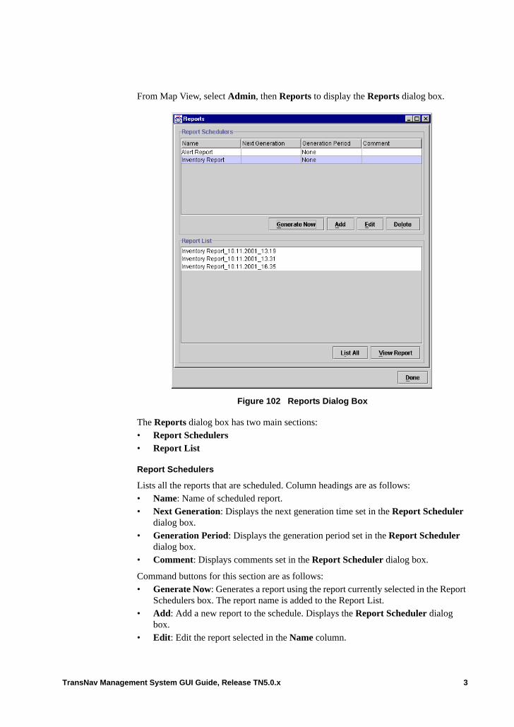
From Map View, select Admin, then Reports to display the Reports dialog box.
Figure 102 Reports Dialog Box
The Reports dialog box has two main sections: • Report Schedulers• Report List
Report Schedulers
Lists all the reports that are scheduled. Column headings are as follows:• Name: Name of scheduled report.• Next Generation: Displays the next generation time set in the Report Scheduler
dialog box.• Generation Period: Displays the generation period set in the Report Scheduler
dialog box.• Comment: Displays comments set in the Report Scheduler dialog box.
Command buttons for this section are as follows:• Generate Now: Generates a report using the report currently selected in the Report
Schedulers box. The report name is added to the Report List.• Add: Add a new report to the schedule. Displays the Report Scheduler dialog
box.• Edit: Edit the report selected in the Name column.
TransNav Management System GUI Guide, Release TN5.0.x 3
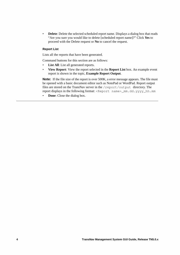
• Delete: Delete the selected scheduled report name. Displays a dialog box that reads “Are you sure you would like to delete [scheduled report name]?” Click Yes to proceed with the Delete request or No to cancel the request.
Report List
Lists all the reports that have been generated.
Command buttons for this section are as follows:• List All: List all generated reports.• View Report: View the report selected in the Report List box. An example event
report is shown in the topic, Example Report Output.
Note: If the file size of the report is over 500K, a error message appears. The file must be opened with a basic document editor such as NotePad or WordPad. Report output files are stored on the TransNav server in the /report/output directory. The report displays in the following format: <Report name>_mm.dd.yyyy_hh.mm• Done: Close the dialog box.
4 TransNav Management System GUI Guide, Release TN5.0.x
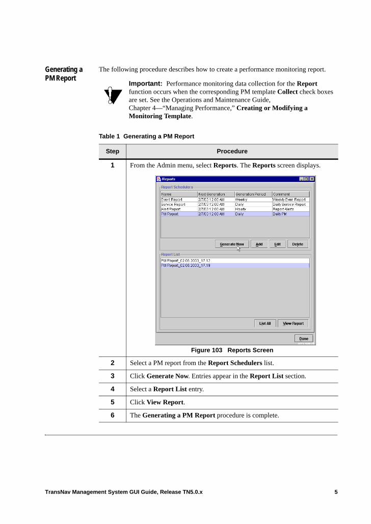
Generating a PM Report
The following procedure describes how to create a performance monitoring report.
Important: Performance monitoring data collection for the Report function occurs when the corresponding PM template Collect check boxes are set. See the Operations and Maintenance Guide, Chapter 4—“Managing Performance,” Creating or Modifying a Monitoring Template.
Table 1 Generating a PM Report
Step Procedure
1 From the Admin menu, select Reports. The Reports screen displays.
Figure 103 Reports Screen
2 Select a PM report from the Report Schedulers list.
3 Click Generate Now. Entries appear in the Report List section.
4 Select a Report List entry.
5 Click View Report.
6 The Generating a PM Report procedure is complete.
TransNav Management System GUI Guide, Release TN5.0.x 5
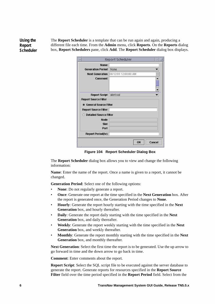
Using the Report Scheduler
The Report Scheduler is a template that can be run again and again, producing a different file each time. From the Admin menu, click Reports. On the Reports dialog box, Report Schedulers pane, click Add. The Report Scheduler dialog box displays.
Figure 104 Report Scheduler Dialog Box
The Report Scheduler dialog box allows you to view and change the following information:
Name: Enter the name of the report. Once a name is given to a report, it cannot be changed.
Generation Period: Select one of the following options:• None: Do not regularly generate a report.• Once: Generate one report at the time specified in the Next Generation box. After
the report is generated once, the Generation Period changes to None.• Hourly: Generate the report hourly starting with the time specified in the Next
Generation box, and hourly thereafter.• Daily: Generate the report daily starting with the time specified in the Next
Generation box, and daily thereafter.• Weekly: Generate the report weekly starting with the time specified in the Next
Generation box, and weekly thereafter.• Monthly: Generate the report monthly starting with the time specified in the Next
Generation box, and monthly thereafter.
Next Generation: Select the first time the report is to be generated. Use the up arrow to go forward in time and the down arrow to go back in time.
Comment: Enter comments about the report.
Report Script: Select the SQL script file to be executed against the server database to generate the report. Generate reports for resources specified in the Report Source Filter field over the time period specified in the Report Period field. Select from the
6 TransNav Management System GUI Guide, Release TN5.0.x
available list of defined script files. For a list of the available report types, see the Operations and Maintenance Guide, Chapter 4—“Managing Performance,” Types of Performance Monitoring Templates
Note: Equipment monitoring events (_eq_performance.sql) are events that cannot be attributed to a specific port or service. For example, excessive traffic on a service or a count of discarded frames where the discards may be the result of improper service configuration. Equipment reports can only be run for Traverse nodes.
Note: To monitor performance on any resource, know how to use the performance monitoring templates. See the Operations and Maintenance Guide, Chapter 4—“Managing Performance.”
Report Source Filter: Allows you to select the source of the information on the report. Valid selections are General Source Filter and Detailed Source Filter. • General Source Filter: Select to run the report run for a specific node in the
domain. The filter is a substring of the Source field parameter and works only if the correct filter is set. – Report Source Filter: Enter the node name of the node to run the report.
• Detailed Source Filter: Select to run a progressively specific report detailing a node name and slot or node name, slot, and port. – Node: Enter the user-defined name of the node.– Slot: Enter the slot number of the card in the shelf (e.g., s-12 for slot 12).– Port: Enter the specific port number on the card in the node. Report Period (hr): Indicates the time over which the report is generated, e.g., enter 4 to specify the report covers the last 4 hours. This parameter is used for the following reports: – alert.sql– event.sql– performance.sql (all performance.sql reports)– resource_availability.sql– service_availability.sql
For example, to filter reports on a specific slot of a specific node, enter only the NodeId and the slot number in this field (e.g., Node1)
In another example for services, use the following syntax:
NodeId/slotNumber/<service member>/vlan-id
where:
NodeId is the user-defined name of the nodeslotNumber is the slot number of the card in the shelf (e.g., s-12 for slot 12)<service member> is the name of the service member<vlan-id> is the vlan ID of the service
To create the report, click OK. The scheduled report appears in the Report Schedulers pane. Once generated, the report displays in the Report List pane in the following format: <Report name>_mm.dd.yyyy_hh.mm
TransNav Management System GUI Guide, Release TN5.0.x 7
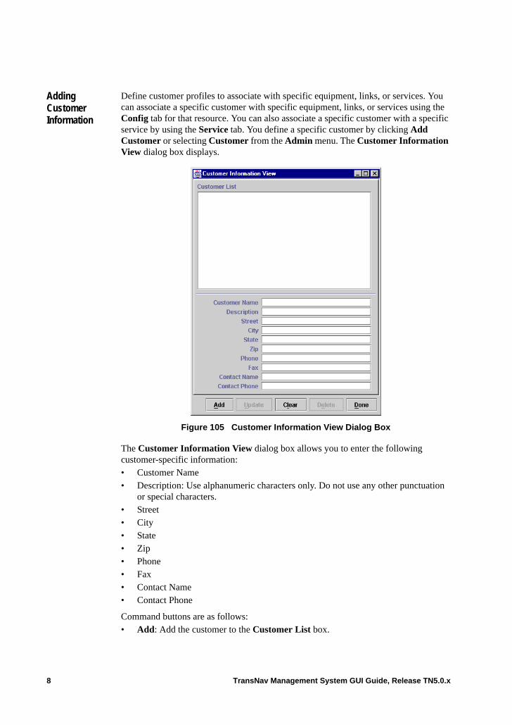
Adding Customer Information
Define customer profiles to associate with specific equipment, links, or services. You can associate a specific customer with specific equipment, links, or services using the Config tab for that resource. You can also associate a specific customer with a specific service by using the Service tab. You define a specific customer by clicking Add Customer or selecting Customer from the Admin menu. The Customer Information View dialog box displays.
Figure 105 Customer Information View Dialog Box
The Customer Information View dialog box allows you to enter the following customer-specific information:• Customer Name• Description: Use alphanumeric characters only. Do not use any other punctuation
or special characters.• Street• City• State• Zip• Phone• Fax• Contact Name• Contact Phone
Command buttons are as follows:• Add: Add the customer to the Customer List box.
8 TransNav Management System GUI Guide, Release TN5.0.x
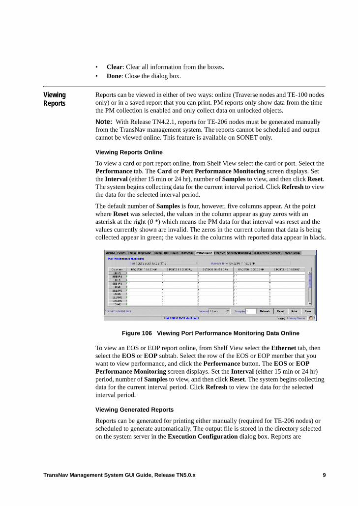
• Clear: Clear all information from the boxes.• Done: Close the dialog box.
Viewing Reports
Reports can be viewed in either of two ways: online (Traverse nodes and TE-100 nodes only) or in a saved report that you can print. PM reports only show data from the time the PM collection is enabled and only collect data on unlocked objects.
Note: With Release TN4.2.1, reports for TE-206 nodes must be generated manually from the TransNav management system. The reports cannot be scheduled and output cannot be viewed online. This feature is available on SONET only.
Viewing Reports Online
To view a card or port report online, from Shelf View select the card or port. Select the Performance tab. The Card or Port Performance Monitoring screen displays. Set the Interval (either 15 min or 24 hr), number of Samples to view, and then click Reset. The system begins collecting data for the current interval period. Click Refresh to view the data for the selected interval period.
The default number of Samples is four, however, five columns appear. At the point where Reset was selected, the values in the column appear as gray zeros with an asterisk at the right (0 *) which means the PM data for that interval was reset and the values currently shown are invalid. The zeros in the current column that data is being collected appear in green; the values in the columns with reported data appear in black.
Figure 106 Viewing Port Performance Monitoring Data Online
To view an EOS or EOP report online, from Shelf View select the Ethernet tab, then select the EOS or EOP subtab. Select the row of the EOS or EOP member that you want to view performance, and click the Performance button. The EOS or EOP Performance Monitoring screen displays. Set the Interval (either 15 min or 24 hr) period, number of Samples to view, and then click Reset. The system begins collecting data for the current interval period. Click Refresh to view the data for the selected interval period.
Viewing Generated Reports
Reports can be generated for printing either manually (required for TE-206 nodes) or scheduled to generate automatically. The output file is stored in the directory selected on the system server in the Execution Configuration dialog box. Reports are
TransNav Management System GUI Guide, Release TN5.0.x 9
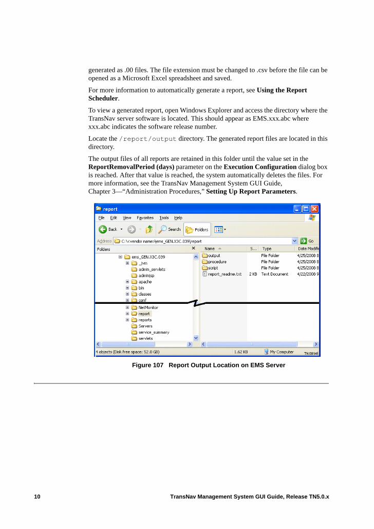
generated as .00 files. The file extension must be changed to .csv before the file can be opened as a Microsoft Excel spreadsheet and saved.
For more information to automatically generate a report, see Using the Report Scheduler.
To view a generated report, open Windows Explorer and access the directory where the TransNav server software is located. This should appear as EMS.xxx.abc where xxx.abc indicates the software release number.
Locate the /report/output directory. The generated report files are located in this directory.
The output files of all reports are retained in this folder until the value set in the ReportRemovalPeriod (days) parameter on the Execution Configuration dialog box is reached. After that value is reached, the system automatically deletes the files. For more information, see the TransNav Management System GUI Guide, Chapter 3—“Administration Procedures,” Setting Up Report Parameters.
Figure 107 Report Output Location on EMS Server
10 TransNav Management System GUI Guide, Release TN5.0.x
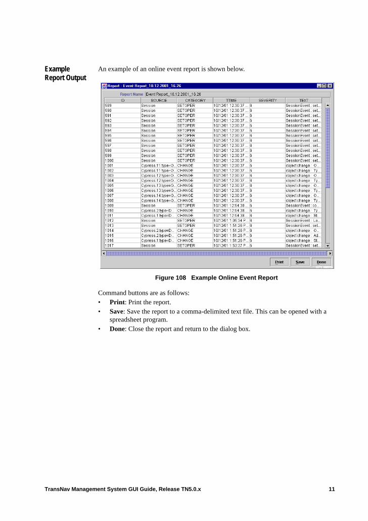
Example Report Output
An example of an online event report is shown below.
Figure 108 Example Online Event Report
Command buttons are as follows:• Print: Print the report.• Save: Save the report to a comma-delimited text file. This can be opened with a
spreadsheet program.• Done: Close the report and return to the dialog box.
TransNav Management System GUI Guide, Release TN5.0.x 11
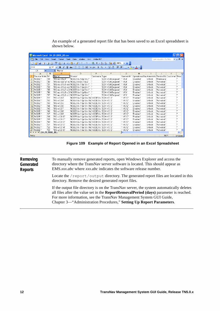
An example of a generated report file that has been saved to an Excel spreadsheet is shown below.
Figure 109 Example of Report Opened in an Excel Spreadsheet
Removing Generated Reports
To manually remove generated reports, open Windows Explorer and access the directory where the TransNav server software is located. This should appear as EMS.xxx.abc where xxx.abc indicates the software release number.
Locate the /report/output directory. The generated report files are located in this directory. Remove the desired generated report files.
If the output file directory is on the TransNav server, the system automatically deletes all files after the value set in the ReportRemovalPeriod (days) parameter is reached. For more information, see the TransNav Management System GUI Guide, Chapter 3—“Administration Procedures,” Setting Up Report Parameters.
12 TransNav Management System GUI Guide, Release TN5.0.x
INDEX
A
Accessgroups
node-level, 2rights, 2
rolesTE-206, 2
Addcard, 7, 10group, 4link, 4node, 4
Alarmssettings
save and import, 3tab
map view, 2shelf view, 6
B
Backgroundchange map, 4images
customizing, 2Backup
databasemanually, 7schedule, 9
Backupsconfiguration files, 1database
multiple servers, 1failure
generated log file, 2
C
Cardconfiguring
DHCP, 33Client type
session list, 9Config tab
map view, 2shelf view, 6
Confirm passworduser
domain, 5
node, 3Craft
GUI, see Graphical user interface, node-level
Customerassociations
equipment, 8links, 8services, 8
create, 8description, 8
Customizenode groups, 3, 6
D
Databasebackups
multiple servers, 1export
manually, 7scheduling, 9
DCC tunneltab
shelf view, 6Delete
card, 8, 11TE-206, 3
DHCPconfigure
node, 33Diagnostics
tabshelf view, 6
Domainroles
access rights, 4user
confirm password, 5create, 5group, 5management by, 5roles, 7set up, 5timeout, 5username, 5, 3
E
Encryption, see Security
TransNav Management System GUI Guide, Release TN5.0.x i
Ethernettab
shelf view, 6Event
tabmap view, 2shelf view, 6
Eventssettings
save and import, 3Export
databasemanually, 7
F
Functional groupsassign
domain users, 3definition, 6roles, 7see also Groups
G
Global blockusers, 40
Graphical user interfaceconventions, 23
resizing windows, 23scroll bars, 23
EMS GUI viewsshelf shortcut menus, 7
node-leveldescriptionguidelines, 10install, 10login, 13starting, 11
shelf view, 5views
map view, shortcut menus, 3TE-100 shelf, shortcut menus, 10
Groupsadd
node, 6change name, 7configuration, 7domain users, 5functional
assign domain users, 3definition
nodebackground images, 2
change name, 13customize, 6
roles, 7
H
Historicalreport
data access, 1Host name, 3, 5, 7, 8, 12HTTPS
logon, 9
I
IconVT switch capability, 5
IP addressDHCP
configuration, 33session list, 9
L
LinkDCC
rediscovery, TE-206 nodes, 1TE-206
discovery, 3Login dialog box
advancednotification, 9, 14port number, 9, 14protocol, 9, 14
connect tonode, 13server, 3, 5, 7, 12
host name, 3, 5, 7, 8, 12, 13HTTPS, 9password, 3, 5, 7, 8, 12, 13user name, 3, 5, 7, 8, 12, 13
M
Map viewalarms tab, 2change background, 4config tab, 2customize image, 31description, 2events tab, 2performance tab, 2protection tab, 2service tab, 2shortcut menu, 3
ii TransNav Management System GUI Guide, Release TN5.0.x
show VT switches, 5VT/VC capability
set, 5Menus, 13
admin, 15node-level GUI, 21
file, 13, 20help, 19provisioning, 19
node-level GUI, 23security
node-level GUI, 22tools
node-level GUI, 22view, 14
node-level GUI, 20Message
daily, 39set up
broadcast, 34daily information, 39security warning, 37
Multiple serversbackups, 1
N
Nodeaccess
groups and rights, 2configuration
DHCP, 33delete
TE-206, 3group
background images, 2change name, 13create, 6customize, 6
GUI, see Graphical user interface, node-level
parametersDHCP, 33
useraccess, 4change password, 2confirm password, 3create, 3management by, 3roles, 4security, 2synchronization, 4
NodesTE-206
enabling in TransNav, 12, 2Notification
login, 9, 14
P
Password, 3, 5, 7, 8, 12change, 2requirements
TE-206, 1user, 5, 3
Performancemonitoring
reports, generating, 1tab
map view, 2shelf view, 6
Point-to-pointprotocol
discovering links, 3Port
numberuser session, 9, 14
Protectiontab
map view, 2shelf view, 6
ProtocolHTTP, 9, 14HTTPS, 9, 14RMI, 9, 14user session, 9, 14
ProvisioningTE-206 nodes see TraverseEdge 206
Users Guide, 2
R
RediscoveryTE-206, 3
Replace card, 8, 11Reports
creating, 1, 6example
Event, 11generate, 1
period, 6generated
location, 9list, 3scheduled, 3scheduler
using, 6script files, 6
TransNav Management System GUI Guide, Release TN5.0.x iii
source filter, 7TE-206
restrictions, 9types, 1viewing, 9
Resizewindows, 23
Restart cardcold, 8, 11warm, 8, 11
Roledomain
access rights, 4user, 7
nodeaccess rightsuser, 4
S
Scheduledatabase
backup, 9Script file
report, 6Scroll bars, 23Security
encryptionenabling, 42
rolessee Domain, rolessee Node, access
Servicetab
map view, 2shelf view, 6
Service Group tabshelf view, 2, 6
Servicessearch
set number to display, 4Session
listclient type, 9IP address, hostname, 9terminate user, 9time logged in, 9user name, currently online, 9
terminationsetting timeout, 5
set up, 39Shelf
viewGUI, 5
Shelf viewdescription, 5service group tab, 2, 6shortcut menu, 7, 10tab
alarms, 6config, 6DCC tunnel, 6diagnostic, 6Ethernet, 6events, 6performance, 6protection, 6service, 6timing, 6
Shortcut menumap view, 3shelf view, 7, 10
Soundoptions
set, 4Synchronization
node user, 4
T
TE-206access roles, 2link
Traverse, 3nodes
enabling in network, 12, 2provisioning
see TraverseEdge 206 Users Guide, 2
TransNavdelete from, 3initial setup, 1prerequisites, 1rediscovery, 3
useraccounts, 2privileges, determining, 1
Telnetconnections
CLI/TL1 termination, 42Terminate
user sessionsbulk, 36
Timelogged in
session list, 9options
set, 4
iv TransNav Management System GUI Guide, Release TN5.0.x
Timeoutdomain user, 5
Timingtab
shelf view, 6TN-Sight
use with TransNav, 1enable TE-206, 12, 2
TransNavrediscovery
TE-206, 3TE-206
discovery prerequisites, 1nodes, 1
use with TN-Sight, 1
U
Useraccess
global block, 40login name, 3name, 5, 7, 8, 12
domain, 5, 3session list, 9
password, 5, 3preferences
save and import, 3time out, 3
privilegesdetermining TE-206, 1
session. bulk delete, 36session.delete domain user, 6session.delete node user, 4sessions
bulk termination, 36Users
passwordTE-206 requirements, 1
V
VT switchingmap view, 5
TransNav Management System GUI Guide, Release TN5.0.x v