Embed Size (px)
Citation preview

2003 IEEE Aerospace Conference, Big Sky, Montana
Transmitting Antenna Modules Refusals Reaction on Wireless PowerTransmission efficiency
Sergey S. ShaposhnikovMoscow Radiotechnical Institute ofThe Russian Academy of Sciences
132 Warshawskoe ShosseMoscow, RU 117519 Russia
7 095 [email protected]
Dimity M. SazonovMoscow Power Engineering Institute
(Technical University)14 Krasnokazarmennaja
Moscow. RU, 111250. Russia7 095 362-7242
Abstract—Research of influence of the transmitting antenna modules refusals on Wireless PowerTransmission (WPT) efficiency and on an angular distribution of side lobe radiation is one of theimportant questions for WPT systems. In the WPT radiating antennas always there is a part ofarray elements, which are refused. Here an admitted percent was calculated. An influence of therefused array elements number on the WPT efficiency was found. Pictures of field distributionon the transmitting and receiving antennas were shown. The number results were obtained due toessential modernization of the Computer Aim Design (CAD).
TABLE OF CONTENTS
1. INTRODUCTION AND GENERAL STATEMENTS 22. TRANSMITTING ANTENNA ARRAY WITH RECTANGULAR APERTURE 43. TRANSMITTING ANTENNA ARRAY WITH CIRCULAR APERTURE 4CONCLUSIONS...............................................10ACKNOWLEDGMENT.....................................12REFERENCES .................................................12
1. INTRODUCTION AND GENERAL STATEMENTS
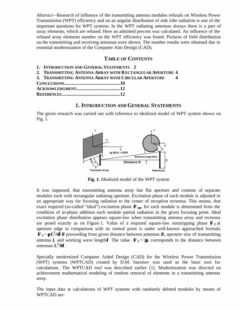
The given research was carried out with reference to idealized model of WPT system shown onFig. 1.
Y
X
Z
L
X
Y
Rectenna Angle (RA)
Distance R D
tg (RA) = D/2R
Transmit Array Rektenna
Fig. 1. Idealized model of the WPT system
It was supposed, that transmitting antenna array has flat aperture and consists of separatemodules each with rectangular radiating aperture. Excitation phase of each module is adjusted inan appropriate way for focusing radiation to the center of reception rectenna. This means, thatexact required (so-called “ideal”) excitation phase ΦΦ opt for each module is determined from thecondition of in-phase addition each module partial radiation in the given focusing point. Idealexcitation phase distribution appears square-law when transmitting antenna array and rectennaare posed exactly as on Figure 1. Value of a required square-law outstripping phase Φ Φ 2 ataperture edge in comparison with its central point is under well-known approached formula Φ Φ 2 ~ ππ L2/4λλR proceeding from given distance between antennas R, aperture size of transmittingantenna L and working wave length λλ The value�. ΦΦ 2 = 2ππ corresponds to the distance betweenantennas L2/8λλ.
Specially modernized Computer Aided Design (CAD) for the Wireless Power Transmission(WPT) systems (WPTCAD) created by D.M. Sazonov was used as the basic tool forcalculations. The WPTCAD tool was described earlier [1]. Modernization was directed onachievement mathematical modeling of random removal of elements in a transmitting antennaarray.
The input data at calculations of WPT systems with randomly deleted modules by means ofWPTCAD are:
1. Transmitting antenna array parameters. They are: form and sizes of the aperture, excitationtype, the type of array grid (rectangular or triangular), parameters of one element, and theoverall number and positions of deleted modules in array aperture;
2. Reception rectenna size, available in a vicinity of a field focusing point transmitting antennaarray. The reception rectenna in WPT system is modeled by round aperture ideally matchedwith free space. It means acceptance of assumption that the rectenna will transformcompletely all falling microwave power to direct current and does not create reradiated fieldin a direction on transmitting antenna array. Calculations of WPT efficiency (it is the PowerTransfer Ratio) were carried out simultaneously in 5 various rectenna diameters in the chosenrange of sizes. It enables a fast finding of the optimum rectenna size, providing required fieldintensity according to the technical requirements.
The following output data are of primary interest at calculations of WPT systems with randomlydeleted modules:
1. WPT efficiency between transmitting antenna system and reception rectenna with variablesize (5 variants simultaneously are used). It is assumed, that rectenna center coincides withfield focusing point of a transmitting antenna array.
2. The required field concentration in a focus point. This parameter is an analogue of directivityfactor for usual antennas.
3. Bi-dimensional and three-dimensional electromagnetic field distribution patterns aroundfocusing point.
The main basic result of our investigations is the creation of the computing subroutine toexamine WPT efficiency of the transmitting antenna arrays with randomly deleted modules. Thissubroutine was organically included in the structure of WPTCAD.
Numerical research of influence of random removal or refusal of some modules in transmittingarray on parameters of WPT system was carried out on two types of transmitting arrays: withrectangular aperture and with circular aperture. There were applied as function in each case: bothuniform and falling down to edges quasi-Gauss distribution of excitation: 0.21+ 0.79 cos2 (ππx/L),where L = full aperture size.
Array steps in a square grid and sizes of radiating elements were chosen identical. For the bestcomparison of results it was supposed, that in rectangular and circular array it should be usedabout identical quantity of transmitting modules. Removal of elements in each realization oftransmitting array was modeled by means of a specially picked up uniform random numbersensor, a generator with zero mean random value and with standard deviation equaled to one.
Results of researches the efficiency for varying percentage of deleted modules were included inthe Figures 4 and 7. Each figure contains WPT Efficiency for 5 various rectenna sizes and forindependent realizations of elements removal in transmitting array. Illustrative field distributionsin focal area, showing changes of side lobe radiation level, also were considered for 10% ofdeleted modules.
The algorithm of elements refusals modeling was extremely simple. Random number in rangefrom 0 to 1 was received from random number generator for each array element during cycle ofelements amplitudes evaluation.
If the received random number was less then the present threshold then the given element wasdeleted, and its amplitude of excitation was adjusted to zero. Special test has shown, that thisalgorithm gave enough uniform distribution of deleted elements in the array aperture.
The analysis of the results shows an opportunity of preservation of serviceability transmittingantenna arrays for WPT systems at full refusals up to 5–10% of transmitting modules. Theincrease of the percent of defected modules up to 10–20% results in essential decrease of powertransfer ratio in WPT system.
2. TRANSMITTING ANTENNA ARRAY WITH RECTANGULAR APERTURE
Research was made on precisely same antenna array, as in the previous paper [2] on research ofinfluence of random phase aperture errors. The array under test contains 41 × 41 = 1681elements. Aperture dimensions of each module are 0.85 from array step. Each side of theaperture in transmitting antenna array is 41.17ë�� Array steps as in X-direction and in Y-directionboth are 0.895ë.
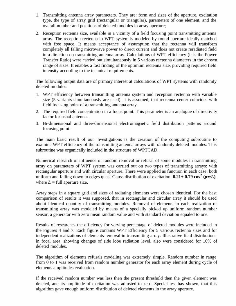
Array aperture picture when the percent number of deleted elements was δδ N/N = 10% is shownon Figure 2a and 3a. These figures were captured from the screen of monitor at runningWPTCAD. Field distributions on focal surface are shown on Figure 2b and on Figure 3b whenδδN/N = 10%, and on Figure 3c and on Figure 4c when δδ N/N = 0%.
The full analysis of WPT system was made for each given percent of deleted modules withseveral independent realizations of distribution of the deleted modules in the aperture. It wasnecessary for an estimation of dispersion of efficiently. It was found out, that the dispersion isvery small, however it tends to increase at increase of percent of deleted modules.
Dispersion grows appreciably for quasi-gauss aperture distributions in comparison with uniformamplitude distribution. And this is natural, as deleted modules with small amplitudes have lowinfluence on the efficiency in comparison with modules with high amplitudes of excitation.
Results of calculations were shown on diagrams (see Figure 4). Conclusions by the receivedresults are given in final section of the report.
3. Transmitting Antenna Array with Circular ApertureThe array under test contains (46 × 46) – 452 = 1664 elements. Aperture dimensions of eachmodule are 0.85 from array step. The aperture diameter in transmitting antenna array is 41.17ë�Array steps in X- and Y-directions are 0.895ë. The circular aperture form was formed due toremoval of 452 angular elements from the square aperture. We shall notice that the number ofelements is less in the given circular array approximately for 1%, than in the rectangular arrayconsidered in section 2.
Array aperture pictures when the percent number of deleted elements was δδ N/N = 10% areshown in Figures 5a and 6a. These figures were captured from a monitor screen runningWPTCAD. Field distributions on focal surface are shown on Figures 6b and 7b whenδδN/N = 10%, and in Figures 5c and 6c when δδ N/N = 0%.
(a)
(b)
(c)
Fig. 2. Square Aperture Transmitting Array with uniform amplitude excitation with δδ N/N =10%; a) aperture view; b) field on focal surface δδ N/N = 10%; c) field on focal surface δδ N/N =0%
(a)
(b)
(c)
Fig. 3. Square Aperture Transmitting Array with Quasi-Gauss excitation and with δδ N/N = 10%:(a) aperture view, (b) field on focal surface δδ N/N = 10%, (c) field on focal surface δδ N/N = 0%.
(a)
(b)
Fig. 4. Square Aperture Transmitting Array Efficiency (a-Uniform, b-Quasi-Gauss). RectennaAngular Size in Degrees: 1–0.8, 2–1.0, 3–1,2, 4–1.6, 5–2,0.
(a)
(b)
(c)
Fig. 5. Circular aperture transmitting array with uniform amplitude excitation with δδ N/N = 10%:(a) aperture view; (b) field on focal surface δδ N/N = 10%; (c) field on focal surface δδ N/N = 0%;
(a)
(b)
(c)
Fig. 6. Circular aperture transmitting array with Quasi-Gauss excitation and with δδ N/N = 10 %;a) aperture view; b) field on focal surface δδ N/N = 10 %; c) field on focal surface δδ N/N = 0 %;
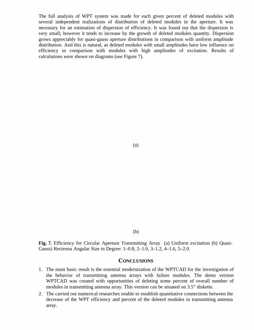
The full analysis of WPT system was made for each given percent of deleted modules withseveral independent realizations of distribution of deleted modules in the aperture. It wasnecessary for an estimation of dispersion of efficiency. It was found out that the dispersion isvery small; however it tends to increase by the growth of deleted modules quantity. Dispersiongrows appreciably for quasi-gauss aperture distributions in comparison with uniform amplitudedistribution. And this is natural, as deleted modules with small amplitudes have low influence onefficiency in comparison with modules with high amplitudes of excitation. Results ofcalculations were shown on diagrams (see Figure 7).
(a)
(b)
Fig. 7. Efficiency for Circular Aperture Transmitting Array (a) Uniform excitation (b) Quasi-Gauss) Rectenna Angular Size in Degree: 1–0.8, 2–1.0, 3–1.2, 4–1.6, 5–2.0.
CONCLUSIONS
1. The main basic result is the essential modernization of the WPTCAD for the investigation ofthe behavior of transmitting antenna arrays with failure modules. The demo versionWPTCAD was created with opportunities of deleting some percent of overall number ofmodules in transmitting antenna array. This version can be situated on 3.5” diskette.
2. The carried out numerical researches enable to establish quantitative connections between thedecrease of the WPT efficiency and percent of the deleted modules in transmitting antennaarray.

3. It is established, that the efficiency of WPT system in separate realizations at identicalnumber of deleted modules has insignificant dispersion of values.
4. It was shown, that it is allowed refusal up to 5–10% from the general number of arraymodules.
5. It follows from submitted results that the physical reason of efficient decrease in WPTsystem with failure modules is the increase of uniformly distributed on space backgroundside lobe radiation. Side lobe radiation extracts power from the central focal beam. Theextracted power is distributed approximately uniformly on space.
6. Accompanying changes of focal beam width and increase of maximal side lobe level areinsignificant at presence no more than 5–10% of failure modules.
7. Antenna array with circular aperture form has advantage in comparison with the rectangularaperture array at identical number of transmitting modules and identical percent of failuremodules.
8. Use of quasi-gauss excitation in transmitting antenna arrays of WPT systems is justified onlyat aspiration to extremely high efficiency (more than 0.7–0.8). For smaller allowableefficiency the transmitting antenna array with uniform excitation has an advantage incomparison with quasi-Gauss array at identical percent allowable efficiency. Thetransmitting antenna array with uniform excitation has advantage in comparison percent ofwith quasi-gauss array at identical deleted modules.

ACKNOWLEDGMENT
The authors would like to thank, engineer E. A. Tsaturyan for the paper edition and InternationalScience and Technology Center (ISTC) who supported this research.
REFERENCES
[1] Sazonov D.M., Microwave Circuits and Antennas. Mir Publishers, Moscow, (ISBN 5-03-001411-X), 1990.
[2] Development of the Method for Producing Electromagnetic Wave Beam with SmallDivergence, 2001 International Science and Technology Center Annual Technical Report on theProject 386-2, May, 2001.


![Design of Ionofree Micro Strip Quad Helix Antenna for ... · antenna, bifilar helices antenna, microstrip antenna, quadrafilar helix antenna. ... Helical antenna [1],[2] is broadband](https://img.pdfslide.us/doc/110x75/5b9506e809d3f2ea5c8b5a04/design-of-ionofree-micro-strip-quad-helix-antenna-for-antenna-bifilar-helices.jpg)


![Confirmations Tentatives Refusals Track 2 as on 18th Oct[1]](https://img.pdfslide.us/doc/110x75/55cf9c87550346d033aa237d/confirmations-tentatives-refusals-track-2-as-on-18th-oct1.jpg)


![1952] PASSPORT REFUSALS FOR POLITICAL REASONS 203](https://img.pdfslide.us/doc/110x75/6191da2fd3365740e86c9375/1952-passport-refusals-for-political-reasons-203.jpg)