Embed Size (px)
Citation preview
8/9/2019 Transmitter Receiver Pulse-Driven Antenna Array With Near-Field Beam-Forming for UWB Subsurface Imaging Radar…
http://slidepdf.com/reader/full/transmitter-receiver-pulse-driven-antenna-array-with-near-field-beam-forming 1/28
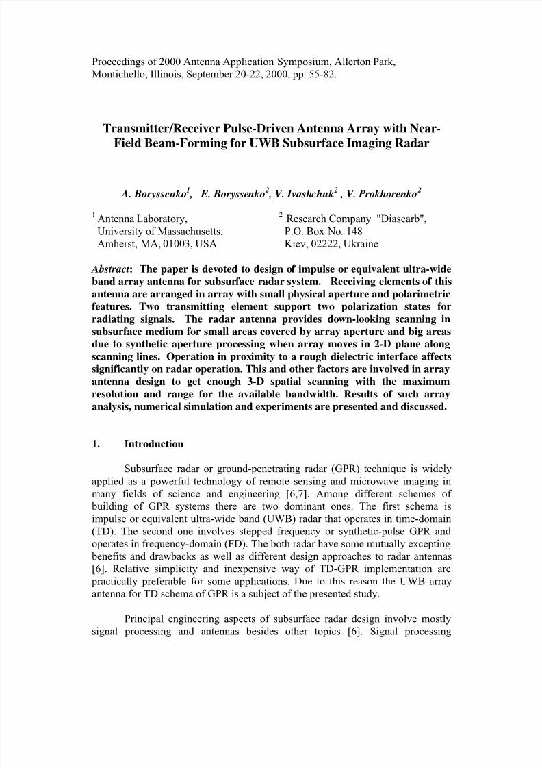
Proceedings of 2000 Antenna Application Symposium, Allerton Park,
Montichello, Illinois, September 20-22, 2000, pp. 55-82.
Transmitter/Receiver Pulse-Driven Antenna Array with Near-
Field Beam-Forming for UWB Subsurface Imaging Radar
A. Boryssenko1 , E. Boryssenko
2 , V. Ivashchuk
2 , V. Prokhorenko
2
1 Antenna Laboratory,
University of Massachusetts,
Amherst, MA, 01003, USA
2 Research Company "Diascarb",
P.O. Box No. 148
Kiev, 02222, Ukraine
Abstract: The paper is devoted to design of impulse or equivalent ultra-wideband array antenna for subsurface radar system. Receiving elements of this
antenna are arranged in array with small physical aperture and polarimetric
features. Two transmitting element support two polarization states for
radiating signals. The radar antenna provides down-looking scanning in
subsurface medium for small areas covered by array aperture and big areas
due to synthetic aperture processing when array moves in 2-D plane along
scanning lines. Operation in proximity to a rough dielectric interface affects
significantly on radar operation. This and other factors are involved in array
antenna design to get enough 3-D spatial scanning with the maximum
resolution and range for the available bandwidth. Results of such array
analysis, numerical simulation and experiments are presented and discussed.
1. Introduction
Subsurface radar or ground-penetrating radar (GPR) technique is widely
applied as a powerful technology of remote sensing and microwave imaging in
many fields of science and engineering [6,7]. Among different schemes of
building of GPR systems there are two dominant ones. The first schema is
impulse or equivalent ultra-wide band (UWB) radar that operates in time-domain
(TD). The second one involves stepped frequency or synthetic-pulse GPR and
operates in frequency-domain (FD). The both radar have some mutually excepting
benefits and drawbacks as well as different design approaches to radar antennas
[6]. Relative simplicity and inexpensive way of TD-GPR implementation are
practically preferable for some applications. Due to this reason the UWB array
antenna for TD schema of GPR is a subject of the presented study.
Principal engineering aspects of subsurface radar design involve mostly
signal processing and antennas besides other topics [6]. Signal processing
8/9/2019 Transmitter Receiver Pulse-Driven Antenna Array With Near-Field Beam-Forming for UWB Subsurface Imaging Radar…
http://slidepdf.com/reader/full/transmitter-receiver-pulse-driven-antenna-array-with-near-field-beam-forming 2/28
Proceedings of 2000 Antenna Application Symposium, Allerton Park,
Montichello, Illinois, September 20-22, 2000, pp. 55-82.
opportunities evolves with progress in computational software/hardware and
digital signal processing. At the same time antennas designers are still situated in
the rigid frame of physical limitations. The last are caused due to inherent and
inaccessible features of impulse antennas loaded by the subsurface interface. Such
features include ringing, impedance mismatching and so on. They cause
degradation of radar performances and GPR antennas are more critical system
component than in air-operated radar [3]. Another sufficient peculiarities of GPR
antenna design are originated from necessity to employ UWB signals for good
range resolution and operation in the near-field range of radar antenna [7].
There are generally two viable approaches for subsurface radar design.
The first way, a designer has to reduce antenna internal reflections and other unwanted phenomena as much as possible, thereby simplifying signal-processing
problem for radar. The second way that realized here is to live with a certain
amount of antenna internal reflections and take those out in signal processing [6].
Therefore some optimal combination of efforts in antenna design and signal
processing technique should be done for each specific system. In our early
attempts [3] we explored behavior of single impulse transmitting (Tx) and
receiving (Rx) antennas in free space and near the air-ground interface. The
impulse array antenna with Rx polarimetric features and two cross-polar Tx
channels is a final goal of array design project described in this work.
The presented array antenna is a principal component of UWB subsurfacedown-looking radar for non-destructive testing of concrete structural elements.
Such GPR should be installed on a robotic platform with remote control for
operation on the radioactive polluted territories near the Chernobyl destroyed
nuclear reactor, Ukraine, in the frame of the big project that is in progress now.
This radar should be employed for detection in thick concrete environment the
metallic inclusions and non-uniform internal regions. Other missions involve
offset 3-D image formation in bistatic 2-D geometry with small base as well as
using synthetic aperture radar (SAR) technique for big survey areas.
The reminder of this paper is organized in the following order. Section 2
gives a glance on key aspects of antenna design for GPR. Some numerical resultswith approximated TD simulation technique are reviewed in Section 3. Design of
UWB antennas with Rx array including single antenna elements, monostatic
antenna pair, 2-element Rx array antenna and end-point array antenna project are
discussed in Section 4. In Section 5 basic algorithms for array data processing
with TD near-range beam-forming for physical aperture, synthetic aperture and
polarimetric techniques are considered. Some experimental results are shown in
Section 6. Final conclusions and reference list are at the end of this paper.
8/9/2019 Transmitter Receiver Pulse-Driven Antenna Array With Near-Field Beam-Forming for UWB Subsurface Imaging Radar…
http://slidepdf.com/reader/full/transmitter-receiver-pulse-driven-antenna-array-with-near-field-beam-forming 3/28
Proceedings of 2000 Antenna Application Symposium, Allerton Park,
Montichello, Illinois, September 20-22, 2000, pp. 55-82.
2. Basic Principles of Impulse Antenna Design
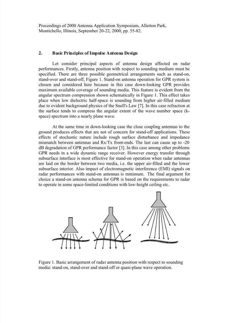
Let consider principal aspects of antenna design affected on radar
performances. Firstly, antenna position with respect to sounding medium must be
specified. There are three possible geometrical arrangements such as stand-on,
stand-over and stand-off, Figure 1. Stand-on antenna operation for GPR system is
chosen and considered here because in this case down-looking GPR provides
maximum available coverage of sounding media. This feature is evident from the
angular spectrum compression shown schematically in Figure 1. This effect takes
place when low dielectric half-space is sounding from higher air-filled medium
due to evident background physics of the Snell's Law [7]. In this case refraction at
the surface tends to compress the angular extent of the wave number space (k-space) spectrum into a nearly plane wave.
At the same time in down-looking case the close coupling antennas to the
ground produces effects that are not of concern for stand-off applications. These
effects of stochastic nature include rough surface disturbance and impedance
mismatch between antennas and Rx/Tx front-ends. The last can cause up to -20
dB degradation of GPR performance factor [3]. In this case among other problems
GPR needs in a wide dynamic range receiver. However energy transfer through
subsurface interface is most effective for stand-on operation when radar antennas
are laid on the border between two media, i.e. the upper air-filled and the lower
subsurface interior. Also impact of electromagnetic interference (EMI) signals onradar performances with stand-on antennas is minimum. The final argument for
choice a stand-on antenna schema for GPR is based on the requirements to radar
to operate in some space-limited conditions with low-height ceiling etc.
Figure 1. Basic arrangement of radar antenna position with respect to sounding
media: stand-on, stand-over and stand-off or quasi-plane wave operation.
8/9/2019 Transmitter Receiver Pulse-Driven Antenna Array With Near-Field Beam-Forming for UWB Subsurface Imaging Radar…
http://slidepdf.com/reader/full/transmitter-receiver-pulse-driven-antenna-array-with-near-field-beam-forming 4/28
Proceedings of 2000 Antenna Application Symposium, Allerton Park,
Montichello, Illinois, September 20-22, 2000, pp. 55-82.
The most fundamental choice in GPR design is a center frequency and a
bandwidth of the radar. Low frequencies provide deeper penetration; the higher
frequencies give better range resolution. The system designer should successfully
resolve this common tradeoff. There are many factors governing the choice of
central frequency related to targets to be detected and electrical properties of
environment where radar to be employed like attenuation in some kind of soils
etc. [4]. Furthermore even for high-resolution subsurface radar a low-frequency
part of spectrum is important too. If high-frequency spectrum provides target
shape and its consistence in detail, the low-frequency one enables target detection
[4]. Evidently here is a practical limitation of low-frequency performance of GPR
antenna determined by its maximum dimension. Note that the near-range field of
pulse antenna contains dominant low-frequency spectrum.
Generally range resolution of the radar is governed by the used bandwidth.
We will show later that the designed array antenna covers 0.2-0.9 GHz band at -
20 dB reference level, which is an optimal one for detection of deep and shallow
targets in concrete. The key antenna candidates to be employed in the designed
array are shown schematically in Figure 2 including dipole, bow-tie, V-shape,
TEM-horn, exponential horn and tapered slot antennas. The choice among those
antennas to be used in radar is based on the following main criteria:
1) accessible bandwidth due to definite geometry;
2) pattern features including directivity and cross-polar level;
3) efficiency of antenna coupling to sounding environment;4) loading performances to be terminated to Tx/Rx front-end devices;
5) implementation feasibility including printed circuit technology;
6) effectiveness of distributive resistive loading to prevent long ringing signals;
7) simplicity of introducing of antenna shielding for interference immunity.
Actually large number of unknowns from environmental conditions to
radar parameters exists in the GPR array antenna design. Application of simulated
data gives parametric estimations useful for array design. Some numerical
simulations of such kind based on computing of approximated models will be
demonstrated in the next section. Due to complexity of overall design of UWB
array antenna with pulse excitation we introduce here some heuristicconsideration. Thus qualitative comparison of antenna types, Figure 2, with
respect to formulated above criterion is presented in Table 1. It is mostly based on
our own experience as well as known literature data [3,6,7]. As followed from
Table 1 the bow-tie antenna is more preferable for Rx mode while TEM or
exponential horn is the best choice for powerful Tx devices where low input
impedance is needed. For low-power Tx antenna bow-tie configuration is also
suitable. For some Rx cases TEM horn and tapered slot antenna can be interesting.

8/9/2019 Transmitter Receiver Pulse-Driven Antenna Array With Near-Field Beam-Forming for UWB Subsurface Imaging Radar…
http://slidepdf.com/reader/full/transmitter-receiver-pulse-driven-antenna-array-with-near-field-beam-forming 5/28
Proceedings of 2000 Antenna Application Symposium, Allerton Park,
Montichello, Illinois, September 20-22, 2000, pp. 55-82.
Dipole Bow-tie
V-shape TEM-horn
Exponential horn Tapered slot
Figure 2. Basic antenna configurations to be chosen for array implementation.
Table 1. Comparison of antenna types for application in UWB GPR.
Dipole bow-tie V-shape TEMhorn
Exponentialhorn
Tapered slot
Relative
Bandwidth
Low Middle low wide wide very wide
Pattern
Directivity
low Low middle high high high
Cross-polar
Level
middle high middle Middle low middle
CouplingFactor
low very high low low low low
InputImpedance
high highmiddle
high low lowmiddle
middlehigh
Production
Complexity
high low high middle high low
Resistive
Loading
difficult difficult difficult difficult difficult difficult
Shielding
Possibility
easy easy difficult difficult difficult difficult

8/9/2019 Transmitter Receiver Pulse-Driven Antenna Array With Near-Field Beam-Forming for UWB Subsurface Imaging Radar…
http://slidepdf.com/reader/full/transmitter-receiver-pulse-driven-antenna-array-with-near-field-beam-forming 6/28
Proceedings of 2000 Antenna Application Symposium, Allerton Park,
Montichello, Illinois, September 20-22, 2000, pp. 55-82.
3. Antenna Analysis in Time Domain
For antenna analysis TD waveform transformations and equivalent FD
spectrum presentation are considered. Both approaches are mathematically
equivalent to be connecting through the Fourier transform. However due to UWB
signal nature and transient antenna operation the TD mathematical modeling is
more relevant and numerically effective. Also experimental TD technique gives
broadband information for test environment that is more simple than using the FD
measurement in an anechroic chamber for much frequency points [3]. Finally we
will consider array beam forming algorithm, which has the best implementation in
TD [12] rather than common FD techniques with k-spectrum presentation [5].
Note that the most of known studies present transient antennas operated in
far-field range while practically sufficient operation range of subsurface radar is
related to the near-field range. There are some principal effects to be carefully
treated for antenna and especially for array antenna due to specific features of
energy distribution in space and time [13] that are different from those presented
in literature for far-filed range operation. In many studies presented in literature
rather than considering the signal waveform and its transformations, analysis and
design are concentrated around the expected spectrum of the return signal after its
propagation to the target, reflection, and propagation back to the radar antenna.
However quality of imaging technique in GPR can be easy estimated by using TD
waveforms, i.e. by specification how long in time its late-time history of radar response or/and how predictable is waveform transformation. Thus TD
presentation is very useful and informative besides traditional FD data.
Ordinary for the transient electromagnetic problems, including antennas,
numerical approaches like FD or TD method of moments or FDTD are applied.
Besides Carl Baum [2] developed analytical approaches with the Laplace
transform for some asymptotic cases. Generally widely used numeric studies have
principal drawback followed from sufficient programming and computing efforts.
Finally the physical meaning of the most numerical solutions is not enough
evident and tedious verification is required. Therefore we developed simple
mathematical models, which enable numerical simulations with universalmathematical software like Maple, Mathcad, Matlab etc. The result of such
simulations will illustrate the major points of our study. The necessity of such
consideration follows from the fact that TD technique in UWB antenna thoery did
not receive yet features of engineering discipline.
To give a glance on the principal choices made in array design we illustrate
some fundamental waveform and spectrum transformations for signal in UWB
8/9/2019 Transmitter Receiver Pulse-Driven Antenna Array With Near-Field Beam-Forming for UWB Subsurface Imaging Radar…
http://slidepdf.com/reader/full/transmitter-receiver-pulse-driven-antenna-array-with-near-field-beam-forming 7/28
Proceedings of 2000 Antenna Application Symposium, Allerton Park,
Montichello, Illinois, September 20-22, 2000, pp. 55-82.
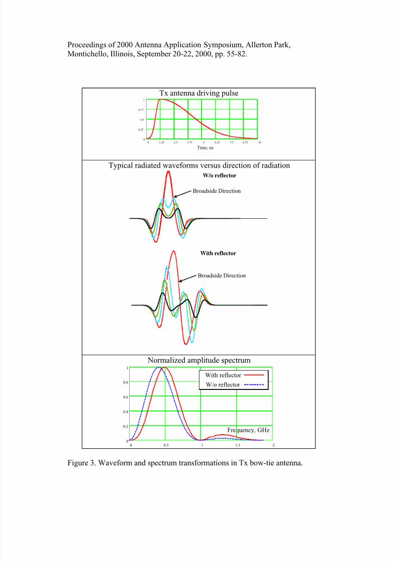
antennas of GPR. Skipping numerous details of mathematical modeling and
numerical simulation, which require special consideration, let present the
fundamental results on signal transformations in pulse driven Tx and Rx antennas
like those in Figures 3 and 4 respectively. Bow-tie antennas are under treatment
here. They are center-excited in double passing mode [3] when they are matched
in the driven point only. Note that for Tx and Rx antennas the specific driven
pulses are applied. These antennas are laid on air-dielectric (ε = 5) interface and
their properties are studied in the intermediate range where the effect of the near-
field is clear visible and discussed later.
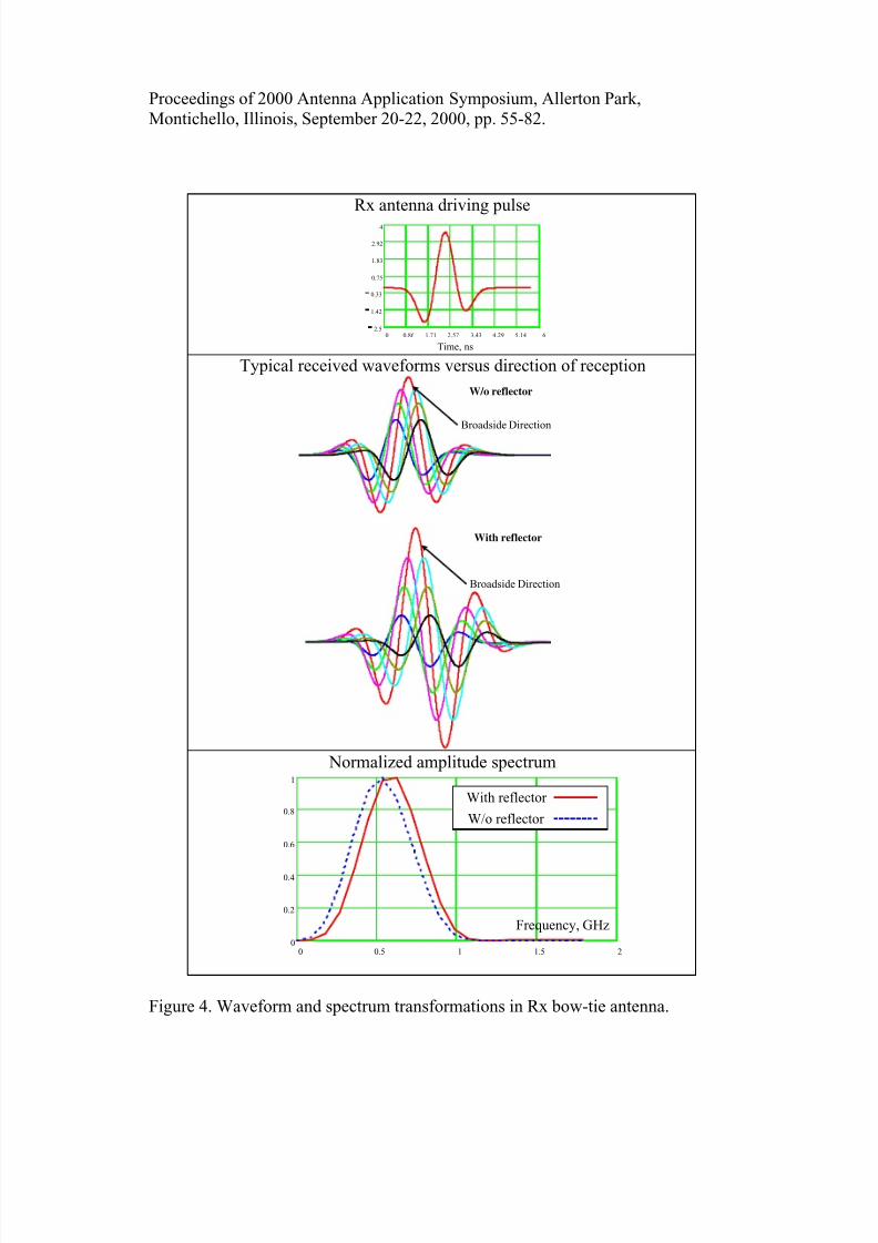
One can observe in Figures 3 and 4 typical waveforms of driven signals in
pulse antennas and other waveform variations versus direction of radiation/reception. Basically the effect of the near field resulted in broader
spectrum in its low-frequency part. If the distance to observation point decreases
the spectrum is broader spread to lower frequencies and DC component appears.
The changing in TD waveforms and frequency spectrum transformations is also
clear visible when reflector is employed in both Tx and Rx antennas. Basically the
reflector shifts slightly spectrum to higher frequencies. Also signal in antenna
with reflector has slightly more duration and amplitude gain up to 6 dB. As
followed from Figures 3 and 4 such antennas demonstrate dominant broadside
radiation where amplitude of signal has maximum value and registered waveform
has specific shape to be useful for its discrimination. At the same time the antenna
pattern is wide spread and special signal processing techniques can improve it.
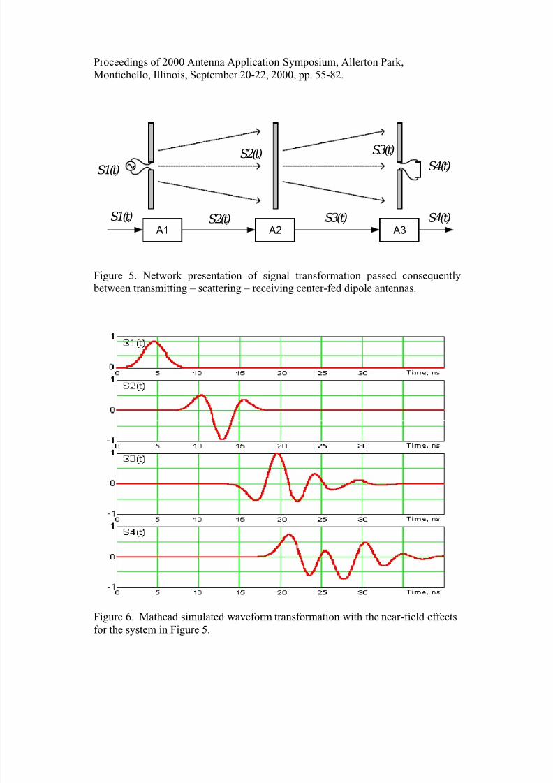
Let consider finally a classical wireless channel to present basic peculiarities
of transient excitation. For far-field range system formed by pair of center-fed,
pulse-driven, linear dipole elements (one terminated to transmitter and other to
receiver) Zialkowski [13] introduced the equivalent network presentation where
main feature is a specific number of time derivatives applied to input waveform.
So far we concentrated on the near-field range effects in antenna we present
transient radio channel model with three same dipole antennas operating in
transmitting, scattering and receiving modes without any limitations concerning
near or far range, antenna type and its excitation. Such generalized system isshown in Figure 4 and can be simulated with mentioned above models. Its own
transformation operators A1,2,3 characterize each antenna in Figure 4. For
example, Figure 5 demonstrates results of Mathcad simulation with respect to the
notations in Figure 4. In this case we have three center-fed dipole antennas with
double passing excitation and the effect of near-field range is observable in these
data.
8/9/2019 Transmitter Receiver Pulse-Driven Antenna Array With Near-Field Beam-Forming for UWB Subsurface Imaging Radar…
http://slidepdf.com/reader/full/transmitter-receiver-pulse-driven-antenna-array-with-near-field-beam-forming 8/28
Proceedings of 2000 Antenna Application Symposium, Allerton Park,
Montichello, Illinois, September 20-22, 2000, pp. 55-82.
Tx antenna driving pulse
Time, ns
0 1.25 2.5 3.75 5 6.25 7.5 8.75 100
0.25
0.5
0.75
1
Typical radiated waveforms versus direction of radiation
W/o reflector
Broadside Direction
Broadside Direction
With reflector
Normalized amplitude spectrum
Frequency, GHz
0 0.5 1 1.5 20
0.2
0.4
0.6
0.8
1
With reflector
W/o reflector
Figure 3. Waveform and spectrum transformations in Tx bow-tie antenna.
8/9/2019 Transmitter Receiver Pulse-Driven Antenna Array With Near-Field Beam-Forming for UWB Subsurface Imaging Radar…
http://slidepdf.com/reader/full/transmitter-receiver-pulse-driven-antenna-array-with-near-field-beam-forming 9/28
Proceedings of 2000 Antenna Application Symposium, Allerton Park,
Montichello, Illinois, September 20-22, 2000, pp. 55-82.
Rx antenna driving pulse
0 0.86 1.71 2.57 3.43 4.29 5.14 62.5
1.42
0.33
0.75
1.83
2.92
4
Time, ns
Typical received waveforms versus direction of reception
W/o reflector
Broadside Direction
With reflector
Broadside Direction
Normalized amplitude spectrum
0 0.5 1 1.5 20
0.2
0.4
0.6
0.8
1
Frequency, GHz
With reflector
W/o reflector
Figure 4. Waveform and spectrum transformations in Rx bow-tie antenna.
8/9/2019 Transmitter Receiver Pulse-Driven Antenna Array With Near-Field Beam-Forming for UWB Subsurface Imaging Radar…
http://slidepdf.com/reader/full/transmitter-receiver-pulse-driven-antenna-array-with-near-field-beam-forming 10/28
Proceedings of 2000 Antenna Application Symposium, Allerton Park,
Montichello, Illinois, September 20-22, 2000, pp. 55-82.
S1(t)
S2(t) S3(t)
S4(t)
A1 A2 A3
S1(t) S2(t) S3(t) S4(t)
Figure 5. Network presentation of signal transformation passed consequently between transmitting – scattering – receiving center-fed dipole antennas.
Figure 6. Mathcad simulated waveform transformation with the near-field effects
for the system in Figure 5.
8/9/2019 Transmitter Receiver Pulse-Driven Antenna Array With Near-Field Beam-Forming for UWB Subsurface Imaging Radar…
http://slidepdf.com/reader/full/transmitter-receiver-pulse-driven-antenna-array-with-near-field-beam-forming 11/28
Proceedings of 2000 Antenna Application Symposium, Allerton Park,
Montichello, Illinois, September 20-22, 2000, pp. 55-82.
4. Antenna Array Design
4.1 Single antenna element design
Waveform and bandwidth having been chosen, the GPR designer must
implement an antenna commensurate with bandwidth. As stated above the antenna
design becomes particularly critical for radar operation near the surface of the
sounding media. In this case some preventing measures are needed to minimize
antenna mismatching and ringing effects. Pure antenna matching can cause
multiple reflections between the antenna and the surface (or within radar itself),
and such "ringing" can hide target returns. Other problems caused by the
proximity of Earth's surface are distortion of the antenna pattern and near-field effects. Both make it more difficult to predict what the GPR should see and hence
make more difficult the interpretation of results.
One of the ways to minimize ringing effect in antenna is implementation
of its resistive loading. However we use antenna without resistive loading rather
antenna with double passing excitation [3]. The reasons are low energy efficiency
and technical difficulty to put in practice resistive loading for big size antennas. It
is easy to show that energy efficiency of such antenna with complete suppression
of wave reflected from opened antenna end will be at least -20 dB lower than in
antenna with double passing of exciting pulse. Also we do not use here impedance
matching technique studied before [3] due to its complexity. Of course for suchdesign preference we have additional lobes in signal and its stretching in time but
we follow here our general design strategy to make simple antenna design and
improve quality of radar imaging as more as possible by signal processing.
Another problem to be treated in design of single antenna element is
minimization EMI effects and false alarm rate due to scattering in upper half-
space. One of the approaches is based on introducing adsorbing materials which
fill some volume above antenna to adsorb electromagnetic energy in above half-
space. But this method being complex for its realization does not give practically
valuable results as followed from our experience and some published data.
Moreover if difference between electrical properties of sounding media and adsorbent material increases the radar performances can degrade and be worse
than in antenna without adsorbent material. The more preferable way is using
antenna with simple reflector. Whole antenna is placed in metallic box with one
open face as an aperture. Additionally about 3dB rise of antenna directive gain is
reached. Note some changing in spectrum take place also as followed from results
of simulation in Section 3.
8/9/2019 Transmitter Receiver Pulse-Driven Antenna Array With Near-Field Beam-Forming for UWB Subsurface Imaging Radar…
http://slidepdf.com/reader/full/transmitter-receiver-pulse-driven-antenna-array-with-near-field-beam-forming 12/28
Proceedings of 2000 Antenna Application Symposium, Allerton Park,
Montichello, Illinois, September 20-22, 2000, pp. 55-82.
Special attention should be paid to optimization of Tx/Rx units with
respect to waveforms in them or equivalent effective spectrum. All discussed
above topics and chosen design preferences have initially been verified with
simple antenna design including monostatic antenna pair, and two Rx and one Tx
channel array antenna. The last one is described at the next section.
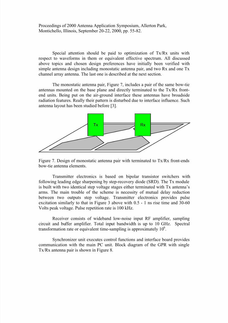
The monostatic antenna pair, Figure 7, includes a pair of the same bow-tie
antennas mounted on the base plane and directly terminated to the Tx/Rx front-
end units. Being put on the air-ground interface these antennas have broadside
radiation features. Really their pattern is disturbed due to interface influence. Such
antenna layout has been studied before [3].
Tx Rx
Figure 7. Design of monostatic antenna pair with terminated to Tx/Rx front-ends
bow-tie antenna elements.
Transmitter electronics is based on bipolar transistor switchers with
following leading edge sharpening by step-recovery diode (SRD). The Tx module
is built with two identical step voltage stages either terminated with Tx antenna’s
arms. The main trouble of the scheme is necessity of mutual delay reduction
between two outputs step voltage. Transmitter electronics provides pulse
excitation similarly to that in Figure 3 above with 0.5 - 1 ns rise time and 30-60
Volts peak voltage. Pulse repetition rate is 100 kHz.
Receiver consists of wideband low-noise input RF amplifier, sampling
circuit and buffer amplifier. Total input bandwidth is up to 10 GHz. Spectral
transformation rate or equivalent time-sampling is approximately 106.
Synchronizer unit executes control functions and interface board provides
communication with the main PC unit. Block diagram of the GPR with single
Tx/Rx antenna pair is shown in Figure 8.

8/9/2019 Transmitter Receiver Pulse-Driven Antenna Array With Near-Field Beam-Forming for UWB Subsurface Imaging Radar…
http://slidepdf.com/reader/full/transmitter-receiver-pulse-driven-antenna-array-with-near-field-beam-forming 13/28
Proceedings of 2000 Antenna Application Symposium, Allerton Park,
Montichello, Illinois, September 20-22, 2000, pp. 55-82.
Synchronizer
Tx Module
Step-Voltage
Generator
Step-Voltage
Generator
Rx Module
RF Baloon
Wideband RF Amplifier
Wideband RF
Amplifier Sampling
Circuit
Buffer
Amplifier ADC
Interfaceto PC
Figure 8. Block diagram of the GPR with single Tx/Rx antenna pair.
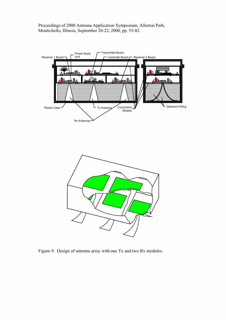
4.2. Two Rx and one Tx module antenna array
The next step of our research and design efforts is to build multi-element
impulse array antenna. It includes two-Rx and one-Tx element array. Draft picture
of this array antenna and accompanied electronics mutual arrangement is shown inFigure 9.
This array is assembled in a single box that forms simultaneously a
shielding package and reflector for whole array antenna. Its inner space is filled
by closed-cell foam plastic. This solution provides simple mechanical support and
reciprocal disposition of antennas, shields and electronics. In order to improve
directivity properties like V-dipole antennas are used instead of bow-tie antennas.
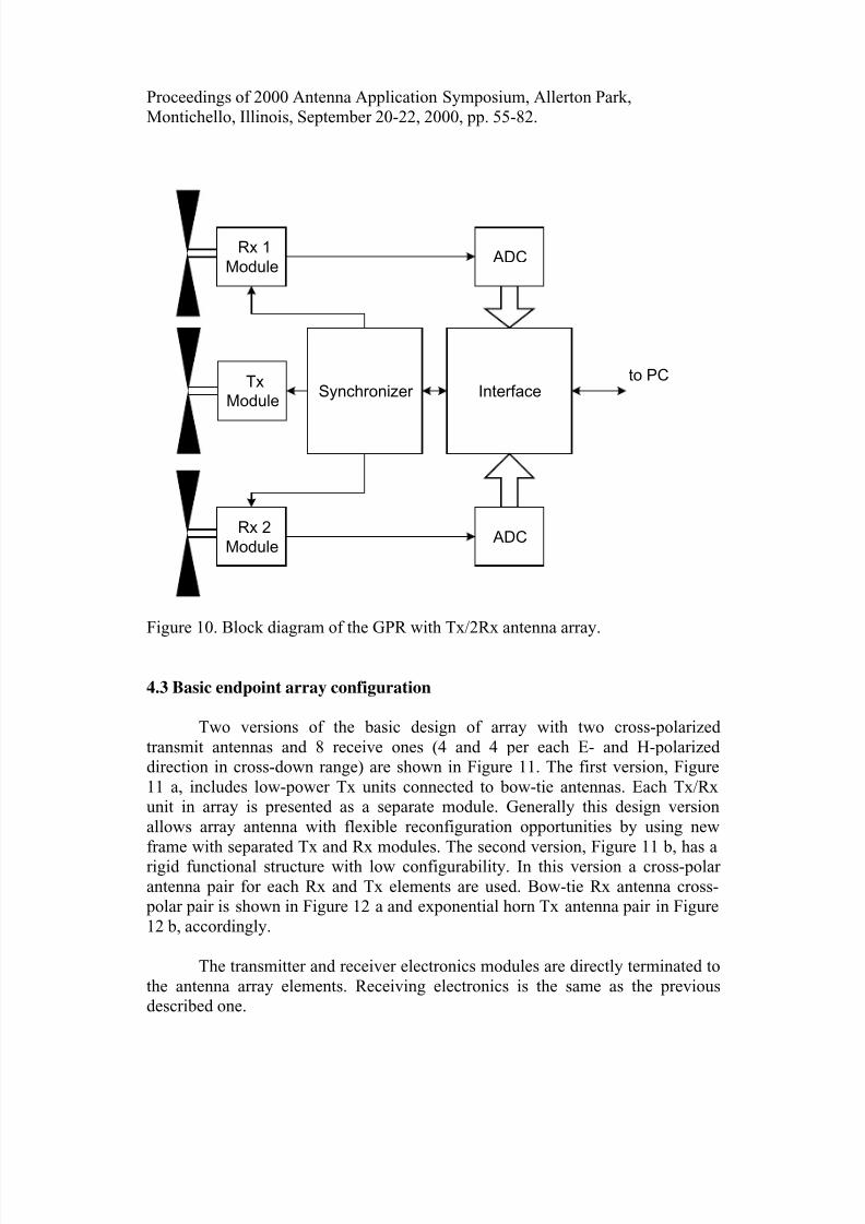
This design is realized with the same Rx and Tx modules, as described
above. The main goal of the construction was simultaneous data acquisition from
several Rx antennas for the principal algorithm examination. Note that considered
data collection strategy assumes replacement of wide-band controlled time-delay
units to computer processing of acquired data. Thereby it eliminates any problems
connected with necessity to compensate mutual delay between different antenna
elements. A block diagram of the GPR with described antenna array design is
shown in Figure 10.
8/9/2019 Transmitter Receiver Pulse-Driven Antenna Array With Near-Field Beam-Forming for UWB Subsurface Imaging Radar…
http://slidepdf.com/reader/full/transmitter-receiver-pulse-driven-antenna-array-with-near-field-beam-forming 14/28
Proceedings of 2000 Antenna Application Symposium, Allerton Park,
Montichello, Illinois, September 20-22, 2000, pp. 55-82.
Plastic Case Conductive
Shields
Controller Board
Power Suply
UnitReceiver 1 Board Receiver 2 Board
Transmitter Board
Tx Antenna
Rx Antennas
Dielectric Filling
Figure 9. Design of antenna array with one Tx and two Rx modules.
8/9/2019 Transmitter Receiver Pulse-Driven Antenna Array With Near-Field Beam-Forming for UWB Subsurface Imaging Radar…
http://slidepdf.com/reader/full/transmitter-receiver-pulse-driven-antenna-array-with-near-field-beam-forming 15/28
Proceedings of 2000 Antenna Application Symposium, Allerton Park,
Montichello, Illinois, September 20-22, 2000, pp. 55-82.
InterfaceTx
Module
ADCRx 2
Module
to PC
ADCRx 1
Module
Synchronizer
Figure 10. Block diagram of the GPR with Tx/2Rx antenna array.
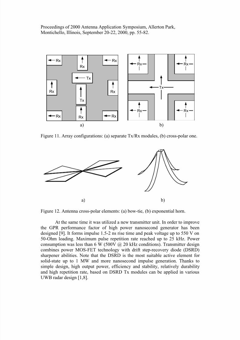
4.3 Basic endpoint array configuration
Two versions of the basic design of array with two cross-polarized
transmit antennas and 8 receive ones (4 and 4 per each E- and H-polarized
direction in cross-down range) are shown in Figure 11. The first version, Figure
11 a, includes low-power Tx units connected to bow-tie antennas. Each Tx/Rx
unit in array is presented as a separate module. Generally this design version
allows array antenna with flexible reconfiguration opportunities by using new
frame with separated Tx and Rx modules. The second version, Figure 11 b, has a
rigid functional structure with low configurability. In this version a cross-polar
antenna pair for each Rx and Tx elements are used. Bow-tie Rx antenna cross-
polar pair is shown in Figure 12 a and exponential horn Tx antenna pair in Figure
12 b, accordingly.
The transmitter and receiver electronics modules are directly terminated to
the antenna array elements. Receiving electronics is the same as the previous
described one.
8/9/2019 Transmitter Receiver Pulse-Driven Antenna Array With Near-Field Beam-Forming for UWB Subsurface Imaging Radar…
http://slidepdf.com/reader/full/transmitter-receiver-pulse-driven-antenna-array-with-near-field-beam-forming 16/28
Proceedings of 2000 Antenna Application Symposium, Allerton Park,
Montichello, Illinois, September 20-22, 2000, pp. 55-82.
Tx
Tx
Rx Rx
Rx Rx
Rx
Rx
Rx Rx
Rx
Rx
Rx
Rx
Tx
a) b)
Figure 11. Array configurations: (a) separate Tx/Rx modules, (b) cross-polar one.
a) b)
Figure 12. Antenna cross-polar elements: (a) bow-tie, (b) exponential horn.
At the same time it was utilized a new transmitter unit. In order to improve
the GPR performance factor of high power nanosecond generator has been
designed [9]. It forms impulse 1.5-2 ns rise time and peak voltage up to 550 V on
50-Ohm loading. Maximum pulse repetition rate reached up to 25 kHz. Power consumption was less than 6 W (500V @ 20 kHz conditions). Transmitter design
combines power MOS-FET technology with drift step-recovery diode (DSRD)
sharpener abilities. Note that the DSRD is the most suitable active element for
solid-state up to 1 MW and more nanosecond impulse generation. Thanks to
simple design, high output power, efficiency and stability, relatively durability
and high repetition rate, based on DSRD Tx modules can be applied in various
UWB radar design [1,8].
8/9/2019 Transmitter Receiver Pulse-Driven Antenna Array With Near-Field Beam-Forming for UWB Subsurface Imaging Radar…
http://slidepdf.com/reader/full/transmitter-receiver-pulse-driven-antenna-array-with-near-field-beam-forming 17/28
Proceedings of 2000 Antenna Application Symposium, Allerton Park,
Montichello, Illinois, September 20-22, 2000, pp. 55-82.
The array covers 0.2-0.9 GHz at -20 dB level as can be predicted from
simulation results in Figures 3 and 4. As discussed above the whole array antenna
has upper shielding for improving system interference immunity and low false
alarm rate. The array antenna width is 1 m on each side. This array antenna
employs ground contact or nearly ground antenna positioning with elevation 0.05-
0.2 m above ground to compensate some surface roughens on the searching areas.
For the sake of enhancing array's performances achieved with physical aperture its
size can be bigger than 1.0x1.0 m.
Such chosen size of the antenna is dictated by requirement to the designed
GPR to be able to operate in some rooms to investigate their underground
environment. Typically these rooms have entrances of 75x150-cm size. From theother hand implementation of SAR technique allows to have bigger equivalent
aperture. Technically this solution is less expensive and simple than
implementation of specialized UWB array antenna with big physical aperture.
Finally SAR approach enables variety of scenarios of data collection including
variable cross-range resolution. The price paid for these advantages are a
relatively slow data-collection rate [6] that is not principal topic for slow moving
robotic platform where the designed GPR with array antenna will be housed.
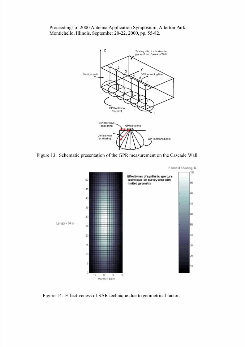
In the case of the designed radar there is necessity to employ array antenna
with definite physical aperture because the SAR technique can not be effectively
applied anywhere. The most important sites of the searching territory near thedestroyed Nuclear Power Plant Unit in Chernobyl are located on so-called
Cascade Walls. Strong edge effect there as shown in Figures 13 does not give
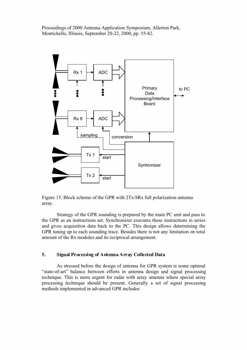
possibility to employ SAR technique there. Efficiency of resulted SAR procedure
computed by estimation of available length of scan lines is shown in Figure 14.
Thus application of some physical aperture in antenna is too necessary.
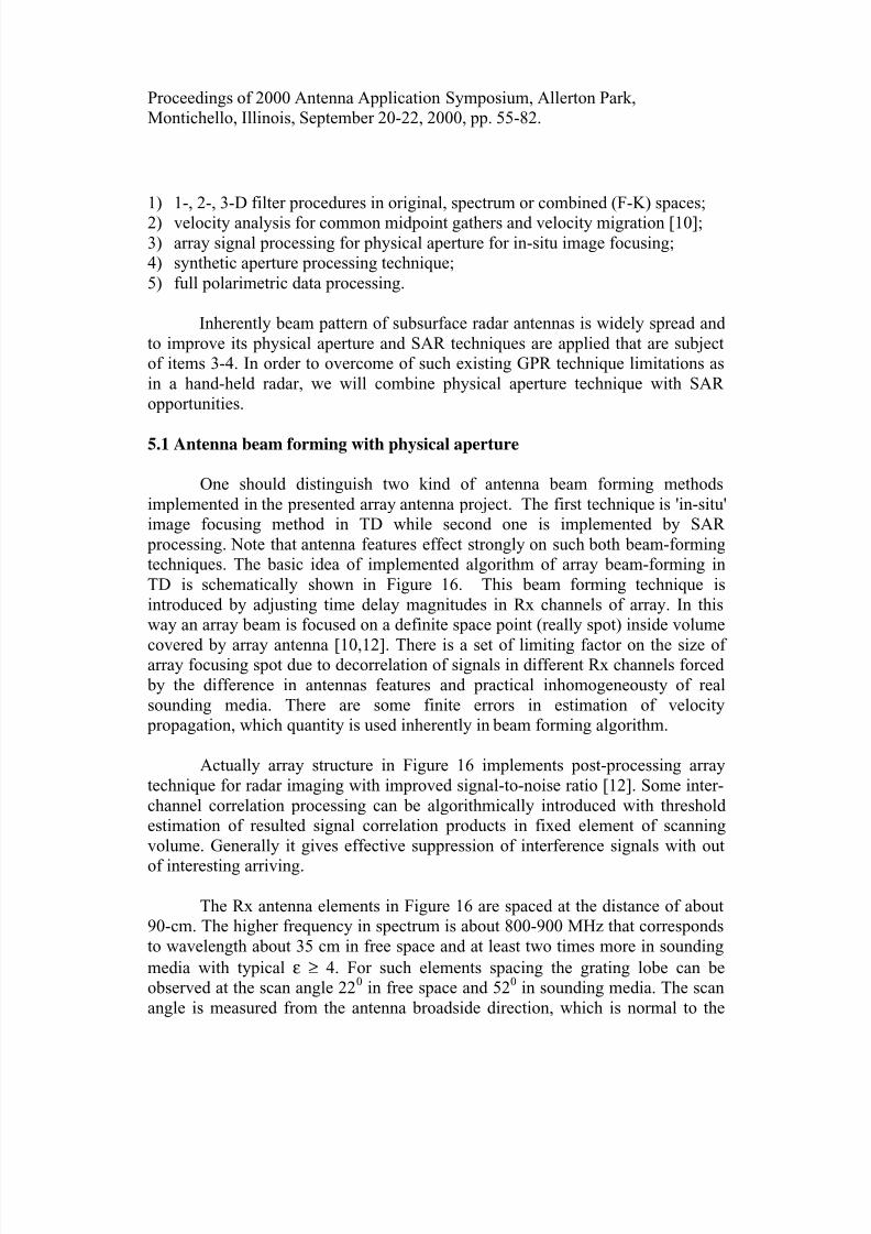
4.4 Array control and data collection subsystem
Block scheme in Figure 15 consists of two Tx and eight Rx modules,synchronizer, data acquisition and interface units. All Rx modules sample and
digitize input signals simultaneously. Mutual delays are removed during primary
digital processing or later. Synchronizer is a “heart” of the system. It forms
control signals for all modules and allows to realize any scanning algorithm under
main computer control. Using digitally controlled sweep-generator and Rx time-
varying gain-control (TVGC) amplifiers allows executing flexible GPR control.
8/9/2019 Transmitter Receiver Pulse-Driven Antenna Array With Near-Field Beam-Forming for UWB Subsurface Imaging Radar…
http://slidepdf.com/reader/full/transmitter-receiver-pulse-driven-antenna-array-with-near-field-beam-forming 18/28
Proceedings of 2000 Antenna Application Symposium, Allerton Park,
Montichello, Illinois, September 20-22, 2000, pp. 55-82.
Z
X
Y
12
3
45
6
Testing site, i .e. horizon tal
plane of the Cascade Walll
GPR scanning line
GPR antenna
footprint
GPR antenna beam
GPR antennaSurface wave
scattering
Vertical wallscattering
Vertical wall
Figure 13. Schematic presentation of the GPR measurement on the Cascade Wall.
Figure 14. Effectiveness of SAR technique due to geometrical factor.
8/9/2019 Transmitter Receiver Pulse-Driven Antenna Array With Near-Field Beam-Forming for UWB Subsurface Imaging Radar…
http://slidepdf.com/reader/full/transmitter-receiver-pulse-driven-antenna-array-with-near-field-beam-forming 19/28
Proceedings of 2000 Antenna Application Symposium, Allerton Park,
Montichello, Illinois, September 20-22, 2000, pp. 55-82.
Primary
Data
Processing/Interface
Board
Tx 1
Tx 2
ADCRx 1
ADCRx 8
Synhronizer
to PC
sampling conversion
start
start
Figure 15. Block scheme of the GPR with 2Tx/8Rx full polarization antenna
array.
Strategy of the GPR sounding is prepared by the main PC unit and pass to
the GPR as an instructions set. Synchronizer executes these instructions in series
and gives acquisition data back to the PC. This design allows determining the
GPR tuning up to each sounding trace. Besides there is not any limitation on total
amount of the Rx modules and its reciprocal arrangement.
5. Signal Processing of Antenna Array Collected Data
As stressed before the design of antenna for GPR system is some optimal
“state-of-art” balance between efforts in antenna design and signal processing
technique. This is more urgent for radar with array antenna where special array
processing technique should be present. Generally a set of signal processing
methods implemented in advanced GPR includes:
8/9/2019 Transmitter Receiver Pulse-Driven Antenna Array With Near-Field Beam-Forming for UWB Subsurface Imaging Radar…
http://slidepdf.com/reader/full/transmitter-receiver-pulse-driven-antenna-array-with-near-field-beam-forming 20/28
Proceedings of 2000 Antenna Application Symposium, Allerton Park,
Montichello, Illinois, September 20-22, 2000, pp. 55-82.
1) 1-, 2-, 3-D filter procedures in original, spectrum or combined (F-K) spaces;
2) velocity analysis for common midpoint gathers and velocity migration [10];
3) array signal processing for physical aperture for in-situ image focusing;
4) synthetic aperture processing technique;
5) full polarimetric data processing.
Inherently beam pattern of subsurface radar antennas is widely spread and
to improve its physical aperture and SAR techniques are applied that are subject
of items 3-4. In order to overcome of such existing GPR technique limitations as
in a hand-held radar, we will combine physical aperture technique with SAR
opportunities.
5.1 Antenna beam forming with physical aperture
One should distinguish two kind of antenna beam forming methods
implemented in the presented array antenna project. The first technique is 'in-situ'
image focusing method in TD while second one is implemented by SAR
processing. Note that antenna features effect strongly on such both beam-forming
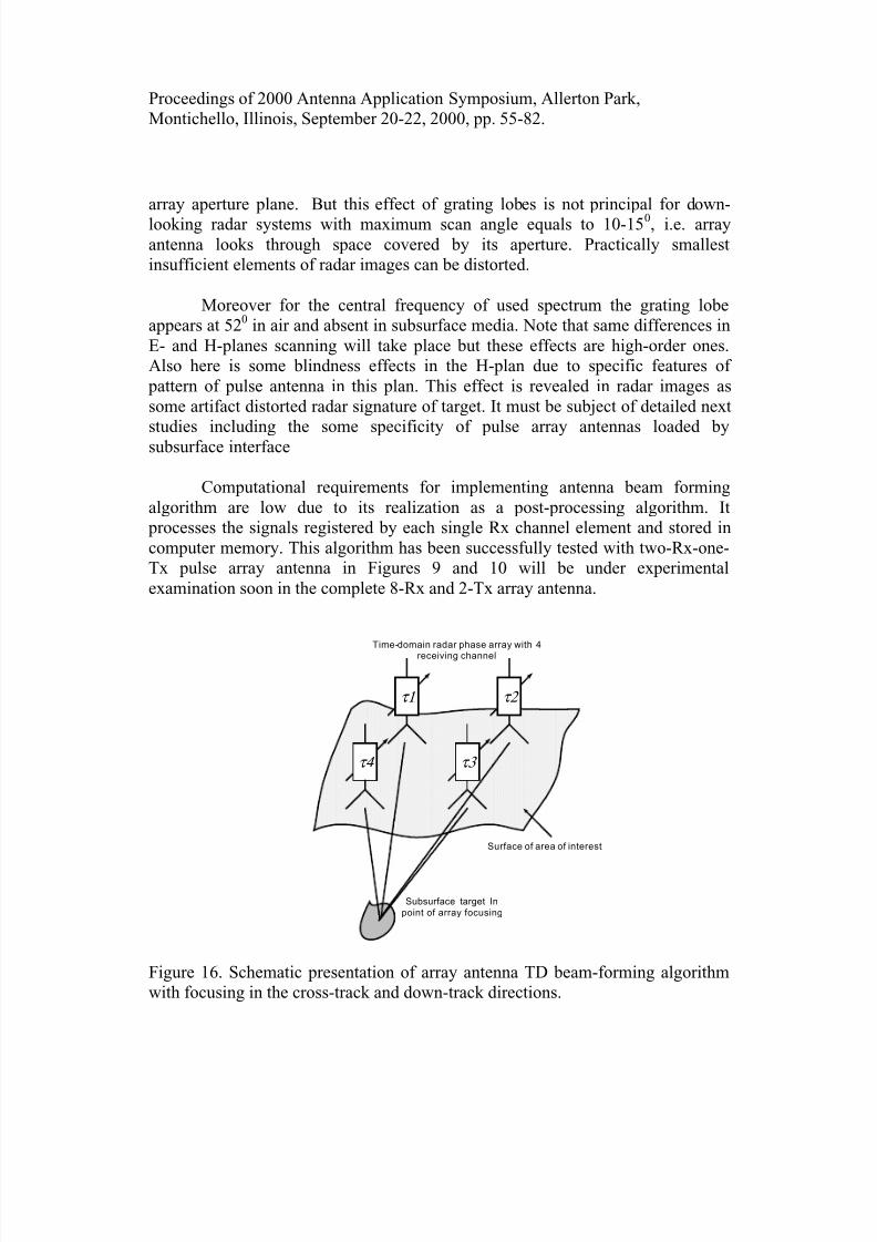
techniques. The basic idea of implemented algorithm of array beam-forming in
TD is schematically shown in Figure 16. This beam forming technique is
introduced by adjusting time delay magnitudes in Rx channels of array. In this
way an array beam is focused on a definite space point (really spot) inside volume
covered by array antenna [10,12]. There is a set of limiting factor on the size of array focusing spot due to decorrelation of signals in different Rx channels forced
by the difference in antennas features and practical inhomogeneousty of real
sounding media. There are some finite errors in estimation of velocity
propagation, which quantity is used inherently in beam forming algorithm.
Actually array structure in Figure 16 implements post-processing array
technique for radar imaging with improved signal-to-noise ratio [12]. Some inter-
channel correlation processing can be algorithmically introduced with threshold
estimation of resulted signal correlation products in fixed element of scanning
volume. Generally it gives effective suppression of interference signals with out
of interesting arriving.
The Rx antenna elements in Figure 16 are spaced at the distance of about
90-cm. The higher frequency in spectrum is about 800-900 MHz that corresponds
to wavelength about 35 cm in free space and at least two times more in sounding
media with typical ε ≥ 4. For such elements spacing the grating lobe can be
observed at the scan angle 220 in free space and 520 in sounding media. The scan
angle is measured from the antenna broadside direction, which is normal to the
8/9/2019 Transmitter Receiver Pulse-Driven Antenna Array With Near-Field Beam-Forming for UWB Subsurface Imaging Radar…
http://slidepdf.com/reader/full/transmitter-receiver-pulse-driven-antenna-array-with-near-field-beam-forming 21/28
Proceedings of 2000 Antenna Application Symposium, Allerton Park,
Montichello, Illinois, September 20-22, 2000, pp. 55-82.
array aperture plane. But this effect of grating lobes is not principal for down-
looking radar systems with maximum scan angle equals to 10-150, i.e. array
antenna looks through space covered by its aperture. Practically smallest
insufficient elements of radar images can be distorted.
Moreover for the central frequency of used spectrum the grating lobe
appears at 520 in air and absent in subsurface media. Note that same differences in
E- and H-planes scanning will take place but these effects are high-order ones.
Also here is some blindness effects in the H-plan due to specific features of
pattern of pulse antenna in this plan. This effect is revealed in radar images as
some artifact distorted radar signature of target. It must be subject of detailed next
studies including the some specificity of pulse array antennas loaded bysubsurface interface
Computational requirements for implementing antenna beam forming
algorithm are low due to its realization as a post-processing algorithm. It
processes the signals registered by each single Rx channel element and stored in
computer memory. This algorithm has been successfully tested with two-Rx-one-
Tx pulse array antenna in Figures 9 and 10 will be under experimental
examination soon in the complete 8-Rx and 2-Tx array antenna.
τ1 τ2
τ4 τ3
Subsurface target In
point of array focusing
Surface of area of interest
Time-domain radar phase array with 4
receiving channel
Figure 16. Schematic presentation of array antenna TD beam-forming algorithm
with focusing in the cross-track and down-track directions.
8/9/2019 Transmitter Receiver Pulse-Driven Antenna Array With Near-Field Beam-Forming for UWB Subsurface Imaging Radar…
http://slidepdf.com/reader/full/transmitter-receiver-pulse-driven-antenna-array-with-near-field-beam-forming 22/28
Proceedings of 2000 Antenna Application Symposium, Allerton Park,
Montichello, Illinois, September 20-22, 2000, pp. 55-82.
5.2. Synthetic aperture processing
Generally SAR processing is well-established method to transform the
data collected along a scan trajectory of electrically small real aperture to data
collected with big virtual aperture. Fourier transform is mostly used for such
mathematical operation to transfer from wave-number space (kx, ky, kz) to
Cartesian coordinate space [12]. The broader supports in k-space, i.e. longer scan
trajectories, the finer impulse response in transform space. Practically it requires
enough long scan line for 2-D imaging and enough scanning areas for 3-D radar
imaging. This SAR technique is widely applied in GPR with single monostatic
antenna pair like that in Figure 7.
Practically the strong influence of antenna properties takes place on the
reconstructed SAR images including some defocusing phenomena to focus
simultaneously early and late time response [12]. These affects require special
detailed consideration and are outside frame of the paper. Also as illustrated in
Figures 13-14 the SAR technique has sometimes very limited opportunities when
GPR system must be applied on the sites limited by their areas.
5.3. Polarimetric processing with array antenna
To collect all available information about target the complete polarimetrictechnique is employed when two orthogonal polarizations are consequently
transmitted and simultaneously received. Employing coherent radar, the
polarization scattering matrix (PSM) is processed to provide target shape
information [11]. Real problem should be carefully treated is a level of
polarization isolation of antennas, especially in the near-field range. Our own
results as well as the data in literature indicate about problematic of this issue for
real GPR system especially for shallow target. At the same time this technique is
promising for deeper target. Also using of cross-polarized antennas tends to
discriminate against the surface clutter return. We do not have at this time enough
experimental data on this issue that should be done soon.
Generally the radar polarimetric technique enables potentially target
characterization by fixing the difference in the phase/amplitude/waveform of
signals registered for different polarization states of transmitting Tx1…2 and
receiving Rx1…8 antennas (Figure 15). The scattering matrix for each receiving
element presents measured scattered signals of both polarization S
R E 2,1 versus those
incident transmitted signals I
T E 2,1
8/9/2019 Transmitter Receiver Pulse-Driven Antenna Array With Near-Field Beam-Forming for UWB Subsurface Imaging Radar…
http://slidepdf.com/reader/full/transmitter-receiver-pulse-driven-antenna-array-with-near-field-beam-forming 23/28
Proceedings of 2000 Antenna Application Symposium, Allerton Park,
Montichello, Illinois, September 20-22, 2000, pp. 55-82.
⋅
=
I
T
I
T S
R
S
R
E E
S S
S S
E E
2
1
2221
2111
2
1
Separated radar Rx antennas simultaneously operate in the both polarization states
resulting in four measurements of the co-polar (S11, S22) signals and cross-polar
(S12, S21) ones.
Let note that consequent scanning in two opposite linear polarization does
not make possible target classifications by its polarimetric features. In this case at
least only the S11 and S22 members of the scattering matrix can be estimated. It is
not enough for a proper target characterization that is important issue for highly
clattered media around the Chernobyl destroyed reactor where the designed radar
should be employed.
6. Some Results of Experimental Investigations
Some experimental studies have been conducted with 2-Rx-1-Tx antenna
for GPR design as a prototype of complete 8-Rx-2-Tx array antenna that is in
progress now. The presented experiments are not directly associated with the
Chernobyl radar project but give useful information for our endpoint design.
Firstly additional opportunities of GPR system based on array antenna withrespect to ordinary GPR with monostatic antenna pair to detect and discriminate
the target with specific shape have been explored.
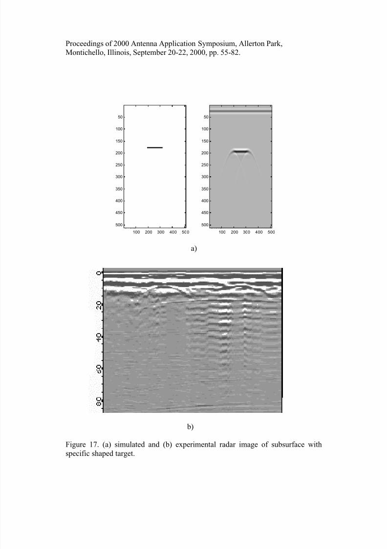
Figure 17 presents simulated and SAR measured data for square metal
plate as a buried target. On the left in Figure 17 a is a 2-D geometry for simplest
subsurface scattering problem to help communicate to next figures. Note that
simulated image at the right of Figure 17 a does not present geometrical shape of
target rather than its signature with specific edge effect expressed in hyperbolic
leading and edge tails [7]. Since radar visualization of internal regions is
inherently more qualitative than quantitative, one must concentrate on the
signature of target than its exact geometrical shape that can not be reconstructed indetails. In the context of our array antenna project we will consider here the
effects of antennas on radar signatures.
In Figure 17 b one can observe the presence of two shallow targets like
that in Figure 17 a. In contrast to simulated data the image of real medium is
different. Here is a direct coupling signal between Tx and Rx antennas [3] as well
as ringing effects at the right side of picture. A ringing effect inside sounding
media is produced by internal interface in it with strong scattering and can be
8/9/2019 Transmitter Receiver Pulse-Driven Antenna Array With Near-Field Beam-Forming for UWB Subsurface Imaging Radar…
http://slidepdf.com/reader/full/transmitter-receiver-pulse-driven-antenna-array-with-near-field-beam-forming 24/28
Proceedings of 2000 Antenna Application Symposium, Allerton Park,
Montichello, Illinois, September 20-22, 2000, pp. 55-82.
partially removed from image by some processing technique. This effect is often
very unwanted for GPR because such clutter obscure valuable information, can
overload internal circuits of receiver and decrease radar dynamical range. There
are no receipts in antenna design other than application full-polarimetric and other
enhanced signal processing techniques that can be effective for some cases.
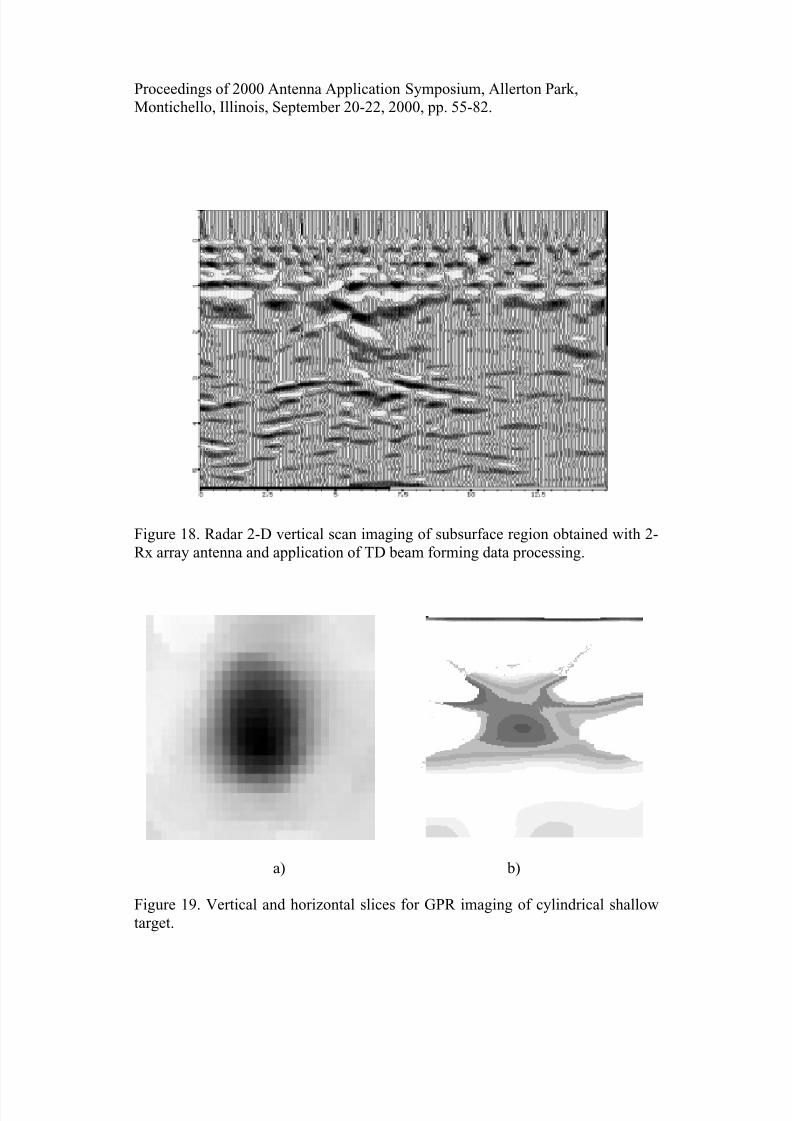
The application of TD beam-forming technique is illustrated in Figure 18
for 2-D scan implemented with 2-Rx-1-Tx radar array antenna. The final image
in this Figure is a result of post processing technique applied to focus image
covered by array aperture. Radar antenna was moved along the straight scan line
and the focused image is computed in broadside direction as cross-correlation of
delayed signals in the Rx channels. Some threshold level was being adjusted toimprove focusing and cut signal tails. We observe here absence of hyperbolic
curves but image has finite level of focusing due to multi-lobe structure of signals.
At the same time some artifacts are present but major reflections are strongly
stressed, which correspond to internal objects should be detected. One can
conclude that this technique is not perfect enough. However we expect that for
such case like the Cascade Wall in Figure 13 it can be useful.
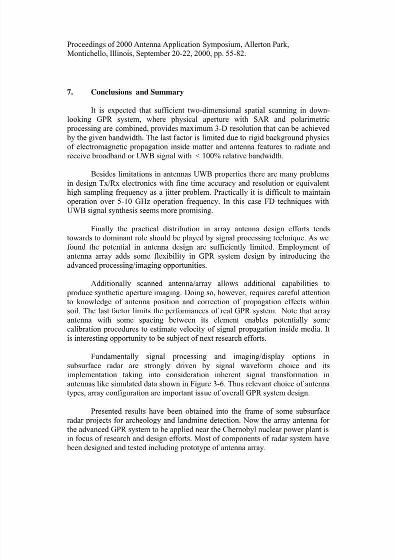
Results of radar imaging of specific subsurface target received with simple
2-Rx and 1-Tx array are shown in Figure 19. At the right one can see horizontal
slice of cylindrical shallow subsurface target and the left picture presents its
vertical slice. This target is like a antitank landmine at the depth of 30 cm and hasthe 35-cm diameter and the 15-cm height. Horizontal slice has been obtained as a
set of linear scan over searching area.
The presented images do not give of course exact geometrical shape of
target being defocused and with artifacts. At the same time to get best quality of
radar images is very problematic. From the point of view of strong physical
limitations it is impossible to obtain better imaging because wavelengths in the
used signal spectrum are comparable with geometrical features of target and
phased information is partially lost. Disturbance effect of medium on antenna and
some uncertainty of signal velocity force the last factor too.
However the results in Figure 19 demonstrate evidently that using of "non-
ideal" antennas in radar with some "ringing" etc. and coherent processing enables
obtaining valuable visualization of subsurface media with GPR. Generally signal-
processing component as sufficient part of design efforts is very important here
and this issue is finally discussed in conclusion section.
8/9/2019 Transmitter Receiver Pulse-Driven Antenna Array With Near-Field Beam-Forming for UWB Subsurface Imaging Radar…
http://slidepdf.com/reader/full/transmitter-receiver-pulse-driven-antenna-array-with-near-field-beam-forming 25/28
Proceedings of 2000 Antenna Application Symposium, Allerton Park,
Montichello, Illinois, September 20-22, 2000, pp. 55-82.
100 200 300 400 500
50
100
150
200
250
300
350
400
450
500
100 200 300 400 500
50
100
150
200
250
300
350
400
450
500
a)
b)
Figure 17. (a) simulated and (b) experimental radar image of subsurface with
specific shaped target.
8/9/2019 Transmitter Receiver Pulse-Driven Antenna Array With Near-Field Beam-Forming for UWB Subsurface Imaging Radar…
http://slidepdf.com/reader/full/transmitter-receiver-pulse-driven-antenna-array-with-near-field-beam-forming 26/28
Proceedings of 2000 Antenna Application Symposium, Allerton Park,
Montichello, Illinois, September 20-22, 2000, pp. 55-82.
Figure 18. Radar 2-D vertical scan imaging of subsurface region obtained with 2-
Rx array antenna and application of TD beam forming data processing.
a) b)
Figure 19. Vertical and horizontal slices for GPR imaging of cylindrical shallow
target.
8/9/2019 Transmitter Receiver Pulse-Driven Antenna Array With Near-Field Beam-Forming for UWB Subsurface Imaging Radar…
http://slidepdf.com/reader/full/transmitter-receiver-pulse-driven-antenna-array-with-near-field-beam-forming 27/28
Proceedings of 2000 Antenna Application Symposium, Allerton Park,
Montichello, Illinois, September 20-22, 2000, pp. 55-82.
7. Conclusions and Summary
It is expected that sufficient two-dimensional spatial scanning in down-
looking GPR system, where physical aperture with SAR and polarimetric
processing are combined, provides maximum 3-D resolution that can be achieved
by the given bandwidth. The last factor is limited due to rigid background physics
of electromagnetic propagation inside matter and antenna features to radiate and
receive broadband or UWB signal with < 100% relative bandwidth.
Besides limitations in antennas UWB properties there are many problems
in design Tx/Rx electronics with fine time accuracy and resolution or equivalent
high sampling frequency as a jitter problem. Practically it is difficult to maintainoperation over 5-10 GHz operation frequency. In this case FD techniques with
UWB signal synthesis seems more promising.
Finally the practical distribution in array antenna design efforts tends
towards to dominant role should be played by signal processing technique. As we
found the potential in antenna design are sufficiently limited. Employment of
antenna array adds some flexibility in GPR system design by introducing the
advanced processing/imaging opportunities.
Additionally scanned antenna/array allows additional capabilities to
produce synthetic aperture imaging. Doing so, however, requires careful attentionto knowledge of antenna position and correction of propagation effects within
soil. The last factor limits the performances of real GPR system. Note that array
antenna with some spacing between its element enables potentially some
calibration procedures to estimate velocity of signal propagation inside media. It
is interesting opportunity to be subject of next research efforts.
Fundamentally signal processing and imaging/display options in
subsurface radar are strongly driven by signal waveform choice and its
implementation taking into consideration inherent signal transformation in
antennas like simulated data shown in Figure 3-6. Thus relevant choice of antenna
types, array configuration are important issue of overall GPR system design.
Presented results have been obtained into the frame of some subsurface
radar projects for archeology and landmine detection. Now the array antenna for
the advanced GPR system to be applied near the Chernobyl nuclear power plant is
in focus of research and design efforts. Most of components of radar system have
been designed and tested including prototype of antenna array.
8/9/2019 Transmitter Receiver Pulse-Driven Antenna Array With Near-Field Beam-Forming for UWB Subsurface Imaging Radar…
http://slidepdf.com/reader/full/transmitter-receiver-pulse-driven-antenna-array-with-near-field-beam-forming 28/28
Proceedings of 2000 Antenna Application Symposium, Allerton Park,
Montichello, Illinois, September 20-22, 2000, pp. 55-82.
References
[1] Agee F. J., Baum C. E., et al, “Ultra-wideband transmitter research”, IEEE
Trans. Plasma Science, 1998, 3, pp. 860.
[2] Baum C., "Some characteristics of electric and magnetic dipole antennas for
radiating transient pulses", Sensor and Simulation Notes, No. 125, 1971.
[3] Boryssenko A., Tarasuk V. "Ultra-wide band impulse antennas for
subsurface radar applications", Proceedings of Antenna Application
Symposium, 1999, pp. 478-504.
[4] Brock B. C., Patitz W.E., “Factors governing of operation frequency for
subsurface-imaging synthetic-aperture radar”, Proceedings of SPIE Conference, SPIE Vol. 2217, 1994, pp. 176-187.
[5] Claude S. et al, "K-space imaging algorithms applied to UWB SAR",
Proceedings of IEEE APS , 1994, pp. 491-495.
[6] Daniels D.J., “System design of radar for mine detection”, Proceedings of
SPIE Conference, SPIE Vol. 3752, 1999, pp. 390-401.
[7] Finkelstein M. I., Mendelson V. L., Kutejev V.A., Radar for layered soils,
Moscow, Soviet Radio, 1977.
[8] Kardo-Sysoev A. F., Zazulin S. V., et al, “High repetition frequency power
nanosecond pulse generation”, Proceedings of the 11th
IEEE Int. PulsePower Conf., 1997, pp. 420.
[9] Prokhorenko V., Boryssenko A., “High power subnanosecond generator for
UWB radar”, Submitted to EUROEM 2000: Euro Electromagnetics, 2000.
[10] Rapport C. M., Reidy D. M., “Focused array radar for real time imaging and
detection”, Proceedings of SPIE Conference, Vol. SPIE 2747, pp. 202-213.
[11] Stiles J. M., Parra-Bocaranda P., Apte A., “Detection of object symmetry
using bistatic and polarimetric GPR observations”, Proceedings of SPIE,
Vol. SPIE 3710, 1999, pp. 992-1002.
[12] Tuo J.S., Buchenauer C.J., Schoenberg J.S.H., "Beamforming in time-domain arrays", Proceedings of APS, 1999, pp. 2014-2017.
[13] Ziolkowski R.W., "Properties of electromagnetic beams generated by ultra-
wide bandwidth pulse-driven arrays", IEEE Trans. on Antenna and
Propagation, Vol. 40, No. 8, August 1992, pp. 888-905.


![UWB Radars [EDocFind.com]](https://img.pdfslide.us/doc/110x75/577d2b9c1a28ab4e1eaae39f/uwb-radars-edocfindcom.jpg)