Embed Size (px)
Citation preview
Transmitter pointing loss calculation for free-space optical communications link analyses William K. Marshall
California Institute of Technology, Jet Propulsion Laboratory, Pasadena, California 91109. Received 17 February 1987. 0003-6935/87/112055-03$02.00/0. © 1987 Optical Society of America.
In calculating the performance of free-space optical communications links, two important factors are the transmitter telescope on-axis gain and the transmitter pointing loss.1 In this Letter we show that the traditional formula for the instantaneous pointing loss (i.e., for the transmitter tele-
1 June 1987 / Vol. 26, No. 11 / APPLIED OPTICS 2055
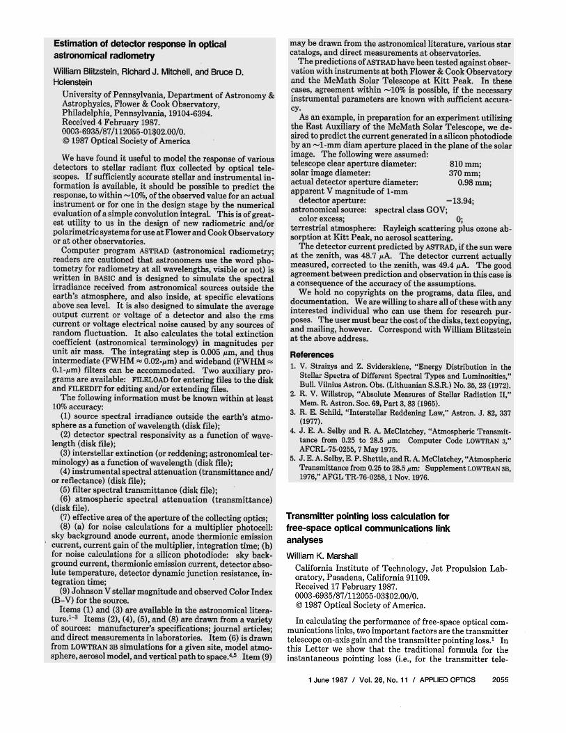
scope far-field beam pattern) is quite inaccurate and that a more accurate (but still simple) approximation exists.
The lowest-order approximations for the telescope gain gt and the transmitter pointing loss lp are obtained by assuming that the telescope has no obscuration and that the laser fills the transmitter aperture with uniform plane-wave illumination. Under these approximations, gt and lp are given by
where A = ττD2/4 is the aperture area, D is the telescope diameter, λ is the wavelength, θ is the off-axis pointing angle, and J1 is the Bessel function of order one.
For more accurate calculations, the effects of the telescope obscuration and of nonuniform aperture lumination should be taken into account. For a central obscuration and plane-wave Gaussian-beam illumination, the far-field telescope gain is given2 by
where 7 is the ratio of the obscuration diameter to the primary aperture diameter, and α is the ratio of the primary diameter to the Gaussian-beam spot diameter. (Normally α is chosen to maximize the far-field gain, in which case α = 1.12 - 1.3072 + 2.1274.) Equation (3) is the formula most often used for the telescope gain in optical link performance analyses.
The pointing loss formula which corresponds to the more accurate gain formula in Eq. (3) is2
The integral in the numerator cannot be reduced, and hence values of lp from this formula must be obtained by numerical integration. As a result, Eq. (4) is almost never used to calculate the pointing loss; Eq. (2) is used instead. Unfortunately, Eq. (2) is not very accurate.
Figure 1 shows pointing loss vs off-axis pointing angle for γ = 0.0, 0.2, and 0.4 calculated numerically using Eq. (4) and also directly from Eq. (2). The figure shows that Eq. (2) is quite inaccurate (except for γ ≃ 0.33) and can give the pointing loss accurately (to within 0.1 dB) only if the pointing loss itself is quite small.
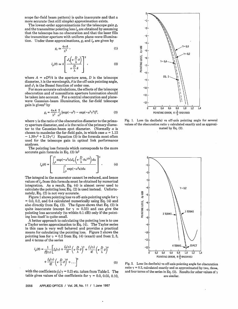
A better approach to calculating the pointing loss is to use a Taylor series approximation to Eq. (4). The Taylor series in this case is very well behaved and provides a practical means for calculating the pointing loss. Figure 2 shows the pointing loss for γ = 0.2 from Eq. (4) (exact) and from 2, 3, and 4 terms of the series
with the coefficients ƒ0(γ = 0.2) etc. taken from Table I. The table gives values of the coefficients for γ = 0.0, 0.05, 0.10,
Fig. 1. Loss (in decibels) vs off-axis pointing angle for several values of the obscuration ratio γ calculated exactly and as approxi
Fig. 2. Loss (in decibels) vs off-axis pointing angle for obscuration ratio γ = 0.2, calculated exactly and as approximated by two, three, and four terms of the series in Eq. (5). Results for other values of γ
are similar.
2056 APPLIED OPTICS / Vol. 26, No. 11 / 1 June 1987
mated by Eq. (2).
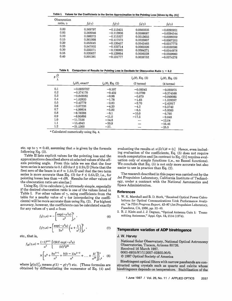
Table I. Values for the Coefficients in the Series Approximation to the Pointing Loss [Given by Eq. (5)]
Table II. Comparison of Results for Pointing Loss in Decibels for Obscuration Ratio 7 = 0.2
etc. up to γ = 0.40, assuming that α is given by the formula following Eq. (3).
Table II lists explicit values for the pointing loss and the approximations described above at selected values of the off-axis pointing angle. From this table we see that the four term series is accurate to 0.1 dB for θ ≤ 0.9λ/D [Note that the first zero of the beam is at θ ≃ 1.3/λD and that the two term series is more accurate than Eq. (2) for θ ≤ 0.6λ/D, i.e., for pointing losses less than ~ 4 dB. Results for other values of the obscuration ratio are similar.]
Using Eq. (5) to calculate lp is extremely simple, especially if the desired obscuration ratio is one of the values listed in Table I. For other values of 7, using coefficients from the table for a nearby value of 7 (or interpolating the coefficients) will be more accurate than using Eq. (2). For highest accuracy, however, the coefficients can be calculated exactly for any values of 7 and a from
etc., that is,
where [g(u)]1γ2 means g(l) - g(γ2) etc. [These formulas are
obtained by differentiating the numerator of Eq. (4) and
evaluating the results at π(D/λ)θ = 0.] Hence, even including evaluation of the coefficients, Eq. (5) does not require much computation and [in contrast to Eq. (2)] requires evaluation only of simple functions (i.e., no Bessel functions). We conclude that Eq. (5) is not only more accurate but also easier to use in practice than Eq. (2).
The research described in this paper was carried out by the Jet Propulsion Laboratory, California Institute of Technology, under a contract with the National Aeronautics and Space Administration.
References 1. W. K. Marshall and B. D. Burk, "Received Optical Power Calcu
lations for Optical Communications Link Performance Analysis," in TDA Progress Report, 42-87 (Jet Propulsion Laboratory, Pasadena, CA, 1986, pp. 32-40.
2. B. J. Klein and J. J. Degnan, "Optical Antenna Gain 1: Transmitting Antennas," Appl. Opt. 13, 2134 (1974).
1 June 1987 / Vol. 26, No. 11 / APPLIED OPTICS 2057