Embed Size (px)
Citation preview
129
1 Introduction
With the rapid development of radio com-munications, radio stations have increased innumber, giving rise to various problems. Theradio interference and jamming, by illegalradio stations, of important or general opera-tional radio communications are the most seri-ous of these problems. According to a recentwhite paper on radio communications, over45,000 incidents were reported in one yearrecently, and the number is on the rise. Effec-tive measures to prevent such illegal actionsand protect the radio environment are urgentlyneeded. To provide reliable and effective reg-ulations against illegal radio communications,
radio monitoring systems are expected to bedeveloped that can identify such radio trans-mission sources through the application of adirection finder and analysis of the propertiesof received radio signals.
In 1992, the Communications ResearchLaboratory (CRL) began a study to identifypress-to-talk transmitters by analyzing theirtransient response characteristics at the time ofbeing switched on and off. In that study, theWigner-Ville distribution, which is a well-known means of analyzing transient responsecharacteristics in acoustic measurements, wasused to identify the transmitters[1].
In 1996, CRL began another study, pro-moted and subsidized by the Ministry of Posts
Masaaki SHIBUKI et al.
Transmitter Identification ―The Devel-opment of a High speed Data AcquisitionSystem with Receiving Functions―Masaaki SHIBUKI, Tsutomu SUGIYAMA, Ken IWASAKI,
Takayuki HIRANO, and Akira SUZUKI
CRL(Communication Research Laboratory) has developed a system that improves theclarity of trigger settings used in the identification of FM radio transmitters. This methoduses a hybrid system that consists of a trigger based high speed data acquisition systemwith receiving functions. This system enhances the ability to accurately identify FM radiotransmitters via a narrow band spectrum trigger system (NSTS) that mediates the variabletransient response patterns the at occur when a press-to-talk button is switched on and off.To accomplish this, an NSTS unit was installed into a high-speed data acquisition system toelicit trigger settings that would provide discrete transmitter identification. This hybrid sys-tem was used to obtain rise and fall data from FM transmitters, and the transient responsepatterns were then analyzed. Experimental evaluation demonstrated that this methodincreases the dynamic range [receiver input level (Pin) = -70 to -110 dBm] and significantlyreduces noise interference, making it possible to obtain more accurate transmitters identifi-cation
Keywords Radio transmitter identification, Narrow band spectrum trigger system(NSTS)
130
and Telecommunications, for the creation of a“Next Generation Radio Monitoring System.”In the first stage of the three year study (April1996 to March 1999), we developed a high-speed data acquisition system for the identifi-cation of transmitters, along with software forusing it. The system was capable of acquiringand displaying RF waveform data or I-Q data,and calculating and displaying spectrogramsbased on the I-Q data.
In the development of the software, westudied methods of analyzing data by applyingan expression for the instantaneous frequency,pseudo-Wigner-Ville distribution, and a spec-trogram to a transient response in the form ofan unsteady state signal. This applicationclarified the characteristics and effectivenessof each method. We then proposed a proce-dure for acquiring spectra using a sequencecorrelation function, based on the high orderexponential function method. This procedurewas compared with conventional methods interms of their time resolution, frequency reso-lution, and noise robustness[2].
In the second stage (April 1999 to March2002), we tested 24 transmitters (six types;manufactured by three companies) by con-ducting an indoor experiment to acquire data.This test was aimed at objectively determiningthe characteristics and tendencies of eachtransmitter. In order to process the data, theamplitude envelope at the time of a rise wasnormalized using the saturation voltage, toallow us to identify transmitters by manufac-turer and type. We also hoped that a differ-ence in the amplitude envelope waveformbetween transmitters of the same type mightbe found, to allow the identification of trans-mitters. A receiver function was added to thehigh speed data acquisition system in order toimprove the software. This allowed data to beacquired through an antenna. Finally, webegan an experiment to examine the effects ofnoise and multi-pass functions on the propaga-tion of radio waves[3].
We investigated two methods of analyzingdata: the root-MUSIC method and the linear-prediction method[4][5]. They were compared
with analyses conducted using an expressionfor the instantaneous frequency, a spectro-gram, and the pseudo-Wigner-Ville distribu-tion. Analyses of the indoor data confirmedthat various patterns existed in the time-fre-quency space for each transmitter model.Unlike in the amplitude waveform, there weremany patterns, and we attempted to extractvery small differences between patterns inorder to identify transmitters. We found,when it was difficult to identify transmittersbased on the amplitude waveform, that addi-tional information on the time-frequencyspace was effective in identification[6]. Wealso began to examine some adaptive equal-ization methods for analyzing signals dam-aged by multi-pass operation or the like. Atwo dimensional CMA and an eigenvectorcomposition method were other topics forstudy in the investigation of the applicabilityof an adaptive array to the radio transmitteridentification system. These methods wereevaluated from the standpoint of performanceby examining spectrograms of their transientresponses[7].
In this report, we will describe animproved radio transmitter identification sys-tem. Prior to the improvement, the lower limitof the receiver input level was -70 dBm whenthe trigger of the transmitter identification sys-tem with an added receiver operated normally.Following the improvement, in which a nar-row band spectrum trigger system was addedto the receiver, the lower limit of the smallestreceiver input level was greatly improved, to-120 dBm.
2 High-speed data-acquisitionsystem
In the course of development, the high-speed data acquisition system was improvedto the capacity of existing systems for indoorexperimental use and outdoor use with anantenna. The indoor experimental structureserved to determine the environmental charac-teristics and power supply dependence of thetransient response under noise free conditions.
Journal of the Communications Research Laboratory Vol.49 No.1 2002
131
The outdoor structure was used to examine theeffectiveness of identifying transmitters byanalyzing acquired data.
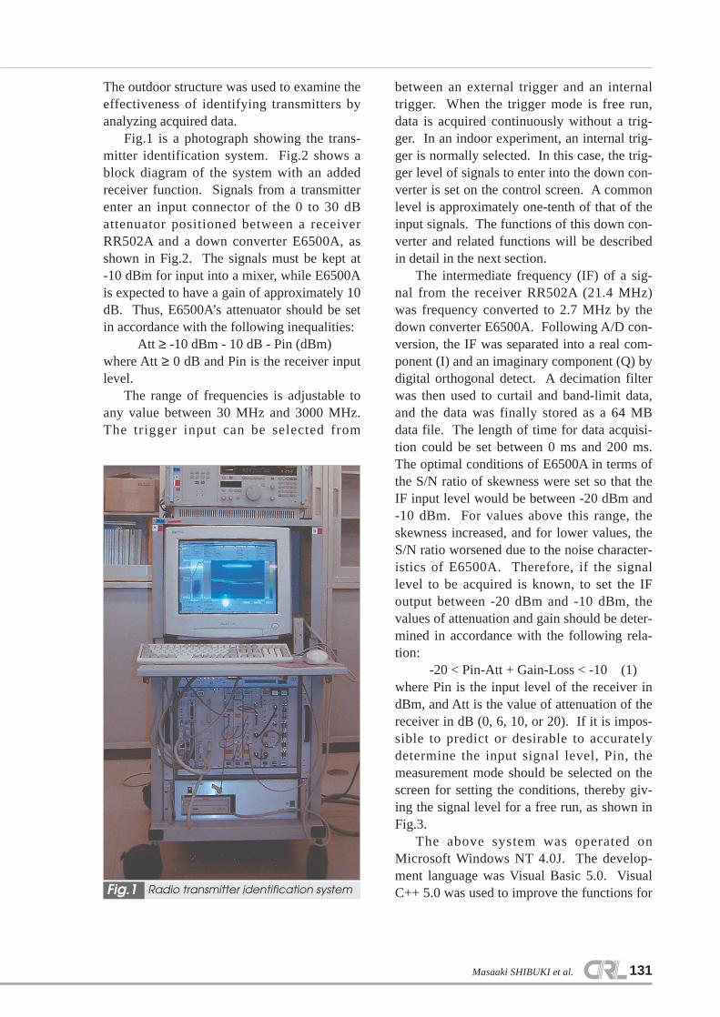
Fig.1 is a photograph showing the trans-mitter identification system. Fig.2 shows ablock diagram of the system with an addedreceiver function. Signals from a transmitterenter an input connector of the 0 to 30 dBattenuator positioned between a receiverRR502A and a down converter E6500A, asshown in Fig.2. The signals must be kept at-10 dBm for input into a mixer, while E6500Ais expected to have a gain of approximately 10dB. Thus, E6500A’s attenuator should be setin accordance with the following inequalities:
Att ≥ -10 dBm - 10 dB - Pin (dBm)where Att ≥ 0 dB and Pin is the receiver inputlevel.
The range of frequencies is adjustable toany value between 30 MHz and 3000 MHz.The trigger input can be selected from
between an external trigger and an internaltrigger. When the trigger mode is free run,data is acquired continuously without a trig-ger. In an indoor experiment, an internal trig-ger is normally selected. In this case, the trig-ger level of signals to enter into the down con-verter is set on the control screen. A commonlevel is approximately one-tenth of that of theinput signals. The functions of this down con-verter and related functions will be describedin detail in the next section.
The intermediate frequency (IF) of a sig-nal from the receiver RR502A (21.4 MHz)was frequency converted to 2.7 MHz by thedown converter E6500A. Following A/D con-version, the IF was separated into a real com-ponent (I) and an imaginary component (Q) bydigital orthogonal detect. A decimation filterwas then used to curtail and band-limit data,and the data was finally stored as a 64 MBdata file. The length of time for data acquisi-tion could be set between 0 ms and 200 ms.The optimal conditions of E6500A in terms ofthe S/N ratio of skewness were set so that theIF input level would be between -20 dBm and-10 dBm. For values above this range, theskewness increased, and for lower values, theS/N ratio worsened due to the noise character-istics of E6500A. Therefore, if the signallevel to be acquired is known, to set the IFoutput between -20 dBm and -10 dBm, thevalues of attenuation and gain should be deter-mined in accordance with the following rela-tion:
-20 < Pin-Att + Gain-Loss < -10 (1)where Pin is the input level of the receiver indBm, and Att is the value of attenuation of thereceiver in dB (0, 6, 10, or 20). If it is impos-sible to predict or desirable to accuratelydetermine the input signal level, Pin, themeasurement mode should be selected on thescreen for setting the conditions, thereby giv-ing the signal level for a free run, as shown inFig.3.
The above system was operated onMicrosoft Windows NT 4.0J. The develop-ment language was Visual Basic 5.0. VisualC++ 5.0 was used to improve the functions for
Masaaki SHIBUKI et al.
Radio transmitter identification systemFig.1

132
graphic drawing and data acquisition. Fig.4shows an example of the RF signal conditionson the control panel. This panel had five tabsto set conditions for the measurement, RF sig-nals, sampling, trigger, and receiver. Thereceiver tab included an item for IF bandwidththat allowed selection from among 12 kHz, 50kHz, and 250 kHz. This system applied therubidium frequency standard as an externalreference signal (10 MHz) for the receiver anddown converter, establishing the accuracy andstability of the frequency. The standard soft-ware for the system included that which
allows the acquisition and display of I-Q data;the display of spectrum waveforms, RF wave-forms, and spectrograms; data processing; andprinting. Fig.5 shows some results obtainedby the system.
A block diagram of the portion that con-tained the prior to improvement internal trig-ger is shown in the upper part of Fig. 2. Thistrigger contained a pre trigger function thatwas capable of acquiring data dating back upto 3 ms. A signal generator was used to evalu-ate the functions of each part of the data-
Journal of the Communications Research Laboratory Vol.49 No.1 2002
Block diagram of the radio transmitter identification system having a receiver functionFig.2
Spectra for a free runFig.3Control panelFig.4

133
acquisition system. No problem was found inany part. After confirming that all of the eval-uation items were complete and acceptable, adata-acquisition test was conducted using anantenna. During this test, the system becameunstable when the RF input signal level wasapproximately -70 dBm, and data acquisitionwas not completed normally. The trigger levelof the system was set in the following way:
Tl (dBm) > Pin (dBm) -10 (dB) (2)
It was found that this system triggered aninput signal into the A/D converter when thewaveform of the signal reached a set value ofthe trigger level. Within the IF band, the noiseis generally white, with a peak value over tentimes the effective value. Thus, when the IFband is enlarged, an adequate trigger levelmay be difficult to set. This proved to be amajor reason for the above mentioned instabil-ity.
Masaaki SHIBUKI et al.
Results obtained by the data-acquisition systemFig.5
134
To solve this problem of instability, wedesigned a portion of the acquisition system asshown in the lower half of Fig.2. This portionwas used to detect the trigger timing for sig-nals containing random noise, and is referredto as a “narrow band trigger system.” Theportion comprised both an A/D converter fordetecting the trigger timing, and adigitizers/signal processor module, and suc-cessfully eliminated random noise to pick up arise in a required signal. It allowed selectionof the bandwidth from among three values:31.25 kHz, 15.63 kHz, and 7.81 kHz. As aresult of the incorporation of such a triggersystem, in an experiment using an antenna,data acquisition was successfully completedeven when Tl = -110 dBm and the IF band-width = 250 kHz for Pin = -120 dBm.
Indoor and outdoor experiments were con-ducted following the above preliminary test.Their results will be described in a separatereport.
3 Conclusions
A narrow band spectrum trigger system(NSTS) was incorporated into a receiver thatwas added to a high speed data acquisition
system for the identification of transmitters.This trigger system improved the dynamicrage for setting the trigger of the data acquisi-tion system, allowing the system to operatewith good stability in a range of antennainput-converted values of Pin = -70 dBm to-120 dBm.
Acknowledgements
The present study was conducted with thefinancial support of the Ministry of Posts andTelecommunications (the current Ministry ofPublic Management, Home Affairs, Posts andTelecommunications). We would like toexpress our appreciation for the assistanceprovided by the persons concerned at the Min-istry and the Communications Research Labo-ratory. We would also like to express our grat-itude to Mr. Yasuo Suzuki and Mr. YoshitadaKato of Agilent Technologies, for aiding in thedevelopment of the data-acquisition system.We wish to thank Mr. Chihiro Miki, SeniorResearcher, for his help with the applicationfor a radio station. Finally, our thanks to Mr.Shunkichi Isobe, Leader of the ScientificTechnology Information Group, for his valu-able advice prior to publication.
Journal of the Communications Research Laboratory Vol.49 No.1 2002
References1 Y.ICHINO, A.SUZUKI, T.SUGIYAMA, H.KAMATA, "Application of wigner-ville distribution for radio
equipment identification", Trans of ieice, Vol.J-B-2 No.10 pp.584-586, Oct.1994(In Japanese).
2 T.HIRANO,"Spectrum using sequential correlation with higher order exponential smoothing", Autumn
conf. of ieice, A-4-21, Sep.1998.
3 T.SUGIYAMA, M.SHIBUKI, T.HIRANO, K.IWASAKI, "Data acquisition system and radio transmitter
rising envelope on radio transmitter identification", Spring conf. of ieice, B-4-23, Mar. 2000.
4 K.IWASAKI, T.HIRANO, M.SHIBUKI, T.SUGIYAMA, "A data analysis method for radio transmitter
identification based on transient response-root-music method-", Spring conf. of ieice, B-4-70, Mar.
1999.
5 K.IWASAKI, T.HIRANO, M.SHIBUKI, T.SUGIYAMA, "A data analysis method for radio transmitter
identification based on transient response-liner-prediction method-", Autumn conf. of ieice, A-4-3,
Sep.1999.
6 T.HIRANO, T.SUGIYAMA, M.SHIBUKI, K.IWASAKI, "Study on time-frequency spectrum pattern for
radio transmitter identification", Sping conf. of ieice, B-4-24, Mar. 2000.
7 K.IWASAKI, M.SHIBUKI, T.SUGIYAMA, "Adaptive array algorithms for radio transmitter identification
based on the trasient response", Trans. of ieice, B, Vol.J84-B, No 7, pp.1233-1238, Jul. 2001.
135Masaaki SHIBUKI et al.
Masaaki SHIBUKI
Senior Researcher, Radio and Meas-urement Technology Group, AppliedResearch and Standards Division
Standard Time and Frequency
Tsutomu SUGIYAMA
Researcher, Radio and MeasurementTechnology Group, Applied Researchand Standards Division
Development of type approval test
Ken IWASAKI
Senior Researcher, Radio and Meas-urement Technology Group, AppliedResearch and Standards Division
Mobile Communications
Akira SUZUKI
Senior Researcher, Research PlanningOffice, Strategic Planning Division
Takayuki HIRANO
STA fellowship