Embed Size (px)
Citation preview

“Transmitarrays, reflectarrays and
phase shifters for wireless
communication systems”
Pablo Padilla de la Torre
Universidad de Granada

2 EI3204 Antenna Theory Course 12th May 2017
Outline
1. Introduction to Transmitarray and Reflectarray structures
2. Passive Transmitarrays
3. Passive Reflectarrays
4. Reconfigurability: Phase shifters
5. Reconfigurable devices: Example

3 EI3204 Antenna Theory Course 12th May 2017
1. Introduction to Transmitarray and Reflectarray structures
4 EI3204 Antenna Theory Course 12th May 2017
Txarray and Rxarray structures
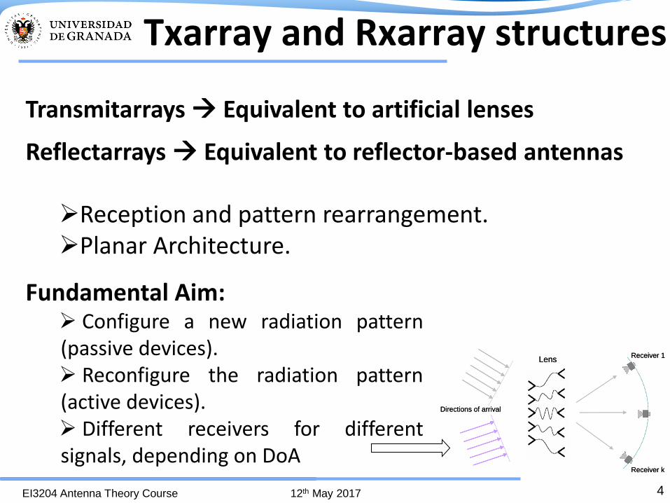
Transmitarrays Equivalent to artificial lenses
Reflectarrays Equivalent to reflector-based antennas Reception and pattern rearrangement. Planar Architecture.
Fundamental Aim: Configure a new radiation pattern (passive devices). Reconfigure the radiation pattern (active devices). Different receivers for different signals, depending on DoA
Lens
Directions of arrival
Receiver 1
Receiver k
Lens
Directions of arrival
Receiver 1
Receiver k

5 EI3204 Antenna Theory Course 12th May 2017
Transmitarray concept:
2. Radiation pattern modification
Transmitarray structures
1. Phase error correction

6 EI3204 Antenna Theory Course 12th May 2017
Reflectarray concept:
1. Phase error correction 2. Radiation pattern modification
Reflectarray structures
7 EI3204 Antenna Theory Course 12th May 2017
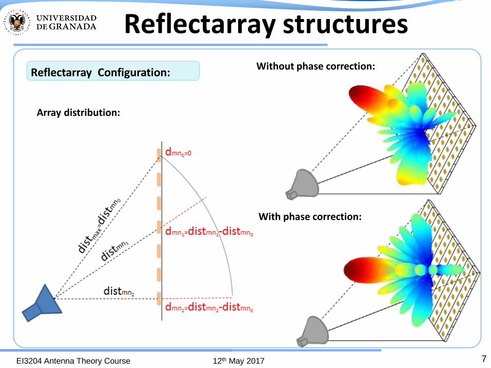
Reflectarray Configuration:
Array distribution:
Without phase correction:
With phase correction:
Reflectarray structures

8 EI3204 Antenna Theory Course 12th May 2017
2. Passive Transmitarrays

9 EI3204 Antenna Theory Course 12th May 2017
Transmitarray configuration:
Passive Transmitarrays
Geometry Applied: Two different geometries analyzed and applied:
Design 1: Multilayer Planar Geometry
•Working frequency: 12 GHz.
•Band width: >0.7 GHz
•Linear polarization.
Particular Specifications:
Design 2: Planar Geometry with plane change
10 EI3204 Antenna Theory Course 12th May 2017
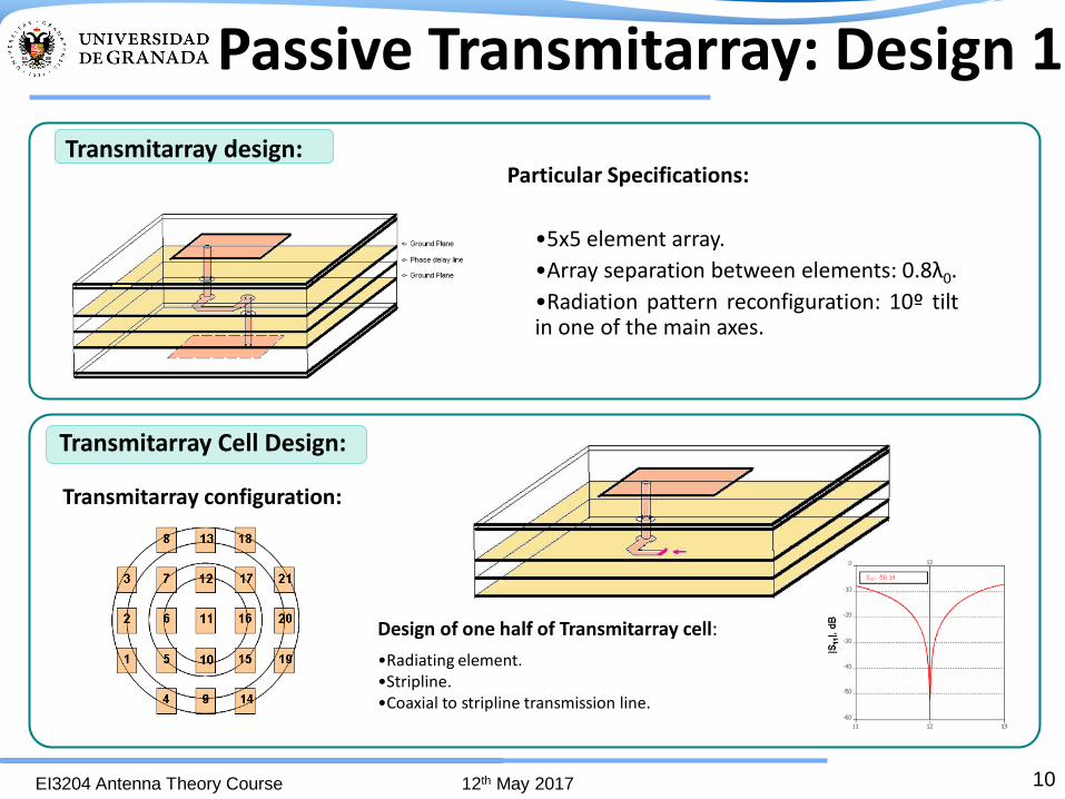
Design of one half of Transmitarray cell:
•Radiating element. •Stripline. •Coaxial to stripline transmission line.
Passive Transmitarray: Design 1
Transmitarray design:
Transmitarray Cell Design:
•5x5 element array.
•Array separation between elements: 0.8λ0.
•Radiation pattern reconfiguration: 10º tilt in one of the main axes.
Particular Specifications:
Transmitarray configuration:

11 EI3204 Antenna Theory Course 12th May 2017
For measurements in the center of cell TRL calibration Kit
Design and Prototypes for Subsystems:
Phase delay line:
Prototype:
Measurement results:
•Coaxial to stripline transmission. •Stripline.
Half transmitarray cell prototype:
dB
Frequency (GHz) 9 10 11 12 13
0
-10
-20
-30
-40
dB
9 10 11 12 13 Frequency (GHz)
0
-10
-20
-30
-40
Passive Transmitarray: Design 1

12 EI3204 Antenna Theory Course 12th May 2017
Design and Prototypes for Subsystems:
Delay line integration
•Coaxial to stripline transmission. •Stripline.
Transmission lines
Vias
Line detail
Complete soldered structure
Patch
array
Patch array integration
Feeding Horn and hanging elements Complete Prototype
Passive Transmitarray: Design 1

13 EI3204 Antenna Theory Course 12th May 2017
Prototype Measurement
•Spherical acquisition chamber •Near field to far field conversion
Theoretical and measured radiation pattern
Phase error correction and 10º tilt in one axis.
Measured Gain: 15.4 dBi. Reduction due to spillover (accepted horn power 42%=-3.7 dB) and circuit losses (1.9dB).
Measuring scheme Copolar
Passive Transmitarray: Design 1

14 EI3204 Antenna Theory Course 12th May 2017
Transmitarray design:
• 10x10 element array. • Stacked patches. • Array separation between
elements: 0.6λ0. • Radiation pattern
reconfiguration: 10º tilt in one of the main axes.
Particular Specifications:
Transmitarray cell design:
Upper Patch
εr=2.17, h=1.575 mm
εr=1.07, h=2 mm
Lower Patch
εr=2.17, h=1.575 mm
Ground Plane
Upper Patch
εr=2.17, h=1.575 mm
εr=1.07, h=2 mm
Lower Patch
εr=2.17, h=1.575 mm
Ground Plane
14
Passive Transmitarray: Design 2
Design of one half of Transmitarray cell: •Stacked patch Radiating element. •Coaxial to microstrip transmission line. •90º change in reference plane. •Microstrip lines

15 EI3204 Antenna Theory Course 12th May 2017
|S11|,
dB
Frequency (GHz)
Patch prototypes:
Prototypes of Subsystems :
Single patch measurement results:
Patch embedded in array:
90º Transition:
|S11|,
dB
Frequency (GHz)
Half transmitarray cell measurement:
Patch + 90º transition+ transmission line:
10 11 12 13 14
8 10 12 14 16
-10
-20
-30
-40
-50
0
-10
-20
-30
-40
-50
8 10 12 14 16
0
-10
-20
-30
Passive Transmitarray: Design 2
16 EI3204 Antenna Theory Course 12th May 2017
Up
per
Lo
wer
Lay
er
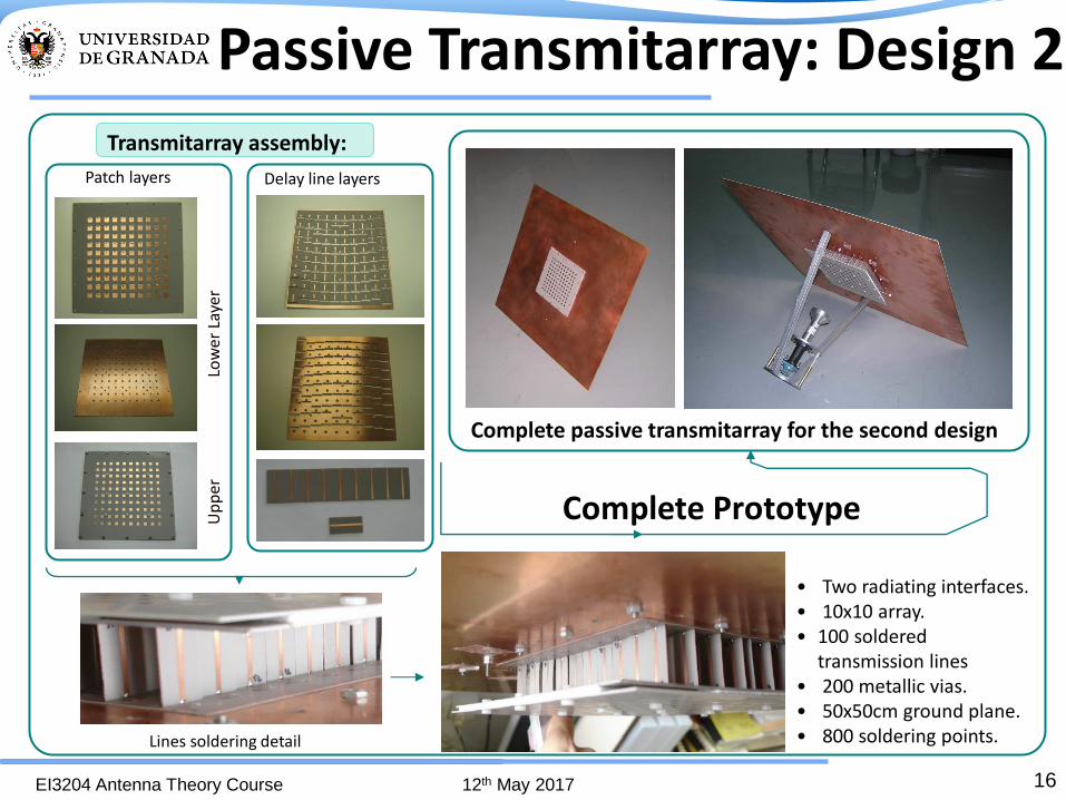
• Two radiating interfaces. • 10x10 array. • 100 soldered
transmission lines • 200 metallic vias. • 50x50cm ground plane. • 800 soldering points.
Complete Prototype
Transmitarray assembly:
Patch layers
Lines soldering detail
Complete passive transmitarray for the second design
Delay line layers
Passive Transmitarray: Design 2

17 EI3204 Antenna Theory Course 12th May 2017
Prototype Measurement:
Theoretical radiation pattern Measured Radiation pattern
For Design 2: Phase error correction and 10º tilt in one main axis
3D measured radiation pattern 2D measured radiation pattern
Measured Gain: 22.5 dBi. Reduction due to spillover (accepted horn power 75%=-1.25 dB) and transmission line losses (1.05 dB) •Spherical acquisition chamber
•Near field to far field conversion
-90 -80 -70 -60 -50 -40 -30 -20 -10 0 10 20 30 40 50 60 70 80 90-40
-35
-30
-25
-20
-15
-10
-5
0
dB
Theta (deg)
Passive Transmitarray: Design 2

18 EI3204 Antenna Theory Course 12th May 2017
3. Passive Reflectarrays
19 EI3204 Antenna Theory Course 12th May 2017
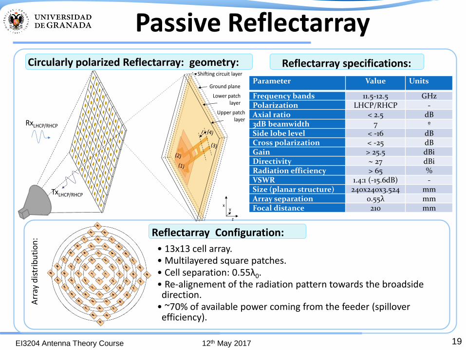
Reflectarray Configuration:
Circularly polarized Reflectarray: geometry:
Arr
ay d
istr
ibu
tio
n:
• 13x13 cell array. • Multilayered square patches. • Cell separation: 0.55λ0. • Re-alignement of the radiation pattern towards the broadside direction.
• ~70% of available power coming from the feeder (spillover efficiency).
Reflectarray specifications:
Parameter Value Units
Frequency bands 11.5-12.5 GHz
Polarization LHCP/RHCP - Axial ratio < 2.5 dB
3dB beamwidth 7 º Side lobe level < -16 dB
Cross polarization < -25 dB
Gain > 25.5 dBi Directivity 27 dBi Radiation efficiency > 65 %
VSWR 1.4:1 (-15.6dB) - Size (planar structure) 240x240x3.524 mm
Array separation 0.55λ mm
Focal distance 210 mm
Ground plane
Shifting circuit layer
Lower patchlayer
Upper patchlayerRxLHCP/RHCP
TxLHCP/RHCP
x
z
y
Passive Reflectarray

20 EI3204 Antenna Theory Course 12th May 2017
Subsystem prototypes: multilayered patches and phase shifters
Isolated cell: Embedded patch in array: Phase shifters:
Passive Reflectarray

21 EI3204 Antenna Theory Course 12th May 2017
Up
per
laye
r
low
er la
yer
Prototyping: Reflectarray assembly
Patch layers:
Complete assembled prototype:
Phase shifting layer:
Passive Reflectarray
22 EI3204 Antenna Theory Course 12th May 2017
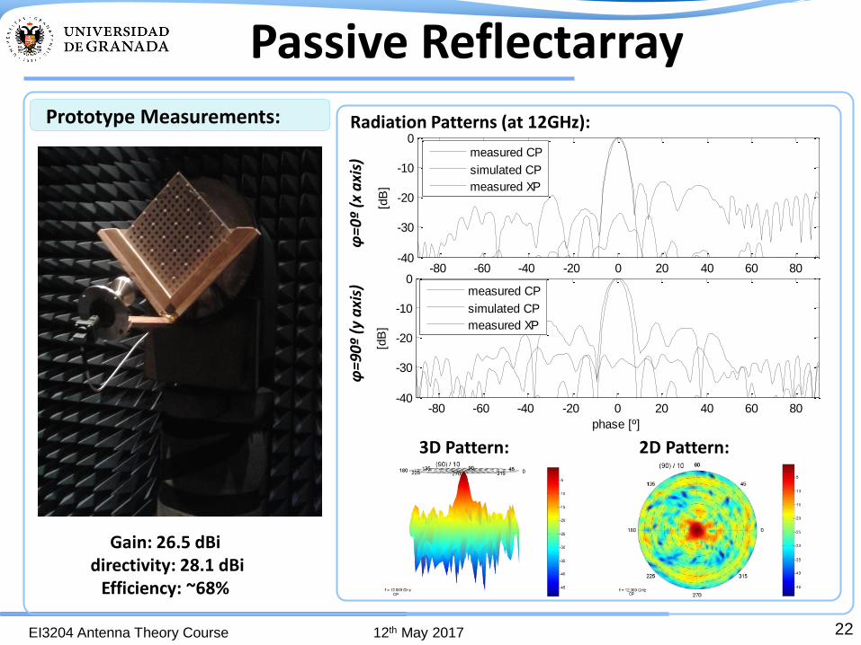
Prototype Measurements: Radiation Patterns (at 12GHz):
3D Pattern: 2D Pattern:
Gain: 26.5 dBi directivity: 28.1 dBi
Efficiency: ~68%
-80 -60 -40 -20 0 20 40 60 80-40
-30
-20
-10
0
phase [º]
[dB
]
measured CP
simulated CP
measured XP
-80 -60 -40 -20 0 20 40 60 80-40
-30
-20
-10
0
phase [º]
[dB
]
measured CP
simulated CP
measured XP
φ=
0º
(x a
xis)
φ
=90º
(y
axi
s)
Passive Reflectarray

23 EI3204 Antenna Theory Course 12th May 2017
Prototype Measurements: Radiation Patterns (11.5-12-12.5 GHz):
Axial Ratio (steering direction):
Gain: 26.5 dBi directivity: 28.1 dBi
Efficiency: ~68%
φ=0º (x axis)
-80 -60 -40 -20 0 20 40 60 80-40
-30
-20
-10
0
phase [º]
[dB
]
12GHz
11.5GHz
12.5GHz
11,5 11,75 12 12,25 12,50
1
2
freq. [GHz]
[dB
]
Passive Reflectarray

24 EI3204 Antenna Theory Course 12th May 2017
4. Reconfigurability: Phase shifters
25 EI3204 Antenna Theory Course 12th May 2017
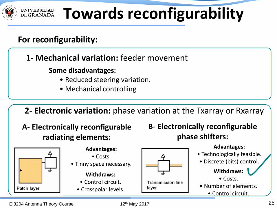
1- Mechanical variation: feeder movement
Towards reconfigurability
B- Electronically reconfigurable phase shifters:
Advantages: • Technologically feasible. • Discrete (bits) control.
Withdraws: • Costs.
• Number of elements. • Control circuit.
A- Electronically reconfigurable radiating elements:
Advantages: • Costs.
• Tinny space necessary.
Withdraws: • Control circuit.
• Crosspolar levels.
For reconfigurability:
2- Electronic variation: phase variation at the Txarray or Rxarray
Some disadvantages: • Reduced steering variation. • Mechanical controlling

26 EI3204 Antenna Theory Course 12th May 2017
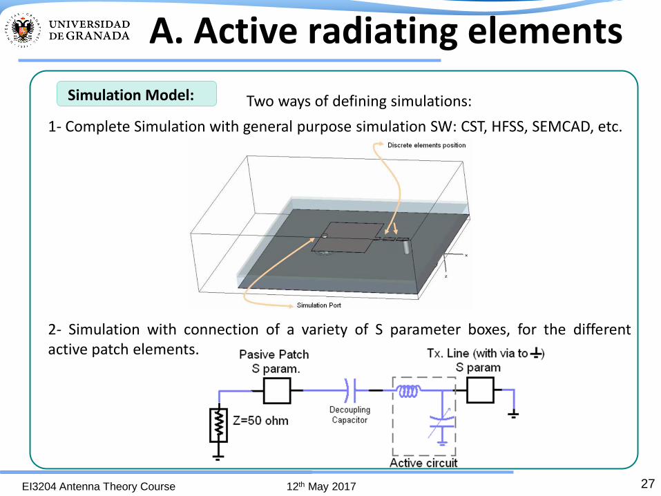
A. Active radiating elements
Basic equivalent Circuit.
Active Patch Scheme: Expected Behavior:
Variation in patch equivalent impedance changes in working frequency changes in the phase behaviour of S parameters.
Patch with surface Varactor:
27 EI3204 Antenna Theory Course 12th May 2017
Two ways of defining simulations:
1- Complete Simulation with general purpose simulation SW: CST, HFSS, SEMCAD, etc.
2- Simulation with connection of a variety of S parameter boxes, for the different active patch elements.
A. Active radiating elements
Simulation Model:

28 EI3204 Antenna Theory Course 12th May 2017
Simulation results with CST:
1st Model (Complete model) With Cmin (0.13 pF)
2nd Model (Boxes model)
With Cmin (0.13 pF)
With Cmax (2.0 pF)
With Cmax (2.0 pF)
A. Active radiating elements

29 EI3204 Antenna Theory Course 12th May 2017
Circuit layout
Varactor
Choke Inductance
Decoupling capacitor
Patch Prototype:
x10
Some active patch details:
x6
•Patch over substrate with εr= 2.17. •Unions with conductive epoxy. •Varactors for microwave purpose.
Measurement Schemes:
Reflection scheme: •S11 •The phase behaviour is assumed to be twice the phase behaviour considered in a transmission scheme.
Transmission scheme: •S12
•The phase behaviour of the patch is directly the measured one.
A. Active radiating elements

30 EI3204 Antenna Theory Course 12th May 2017
Laboratory Measurements
Reflection model:
With Cmax
With Cmin
Transmission model:
With Cmax
With Cmin
A. Active radiating elements
31 EI3204 Antenna Theory Course 12th May 2017
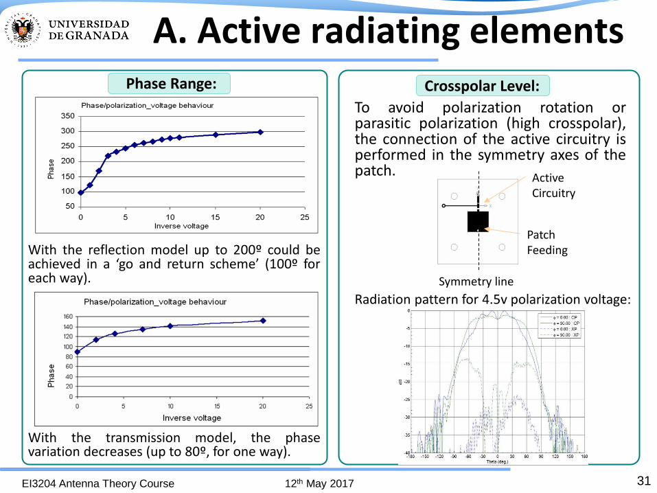
Crosspolar Level:
With the reflection model up to 200º could be achieved in a ‘go and return scheme’ (100º for each way).
With the transmission model, the phase variation decreases (up to 80º, for one way).
To avoid polarization rotation or parasitic polarization (high crosspolar), the connection of the active circuitry is performed in the symmetry axes of the patch.
Symmetry line
Patch Feeding
Active Circuitry
Radiation pattern for 4.5v polarization voltage:
Phase Range:
A. Active radiating elements
32 EI3204 Antenna Theory Course 12th May 2017
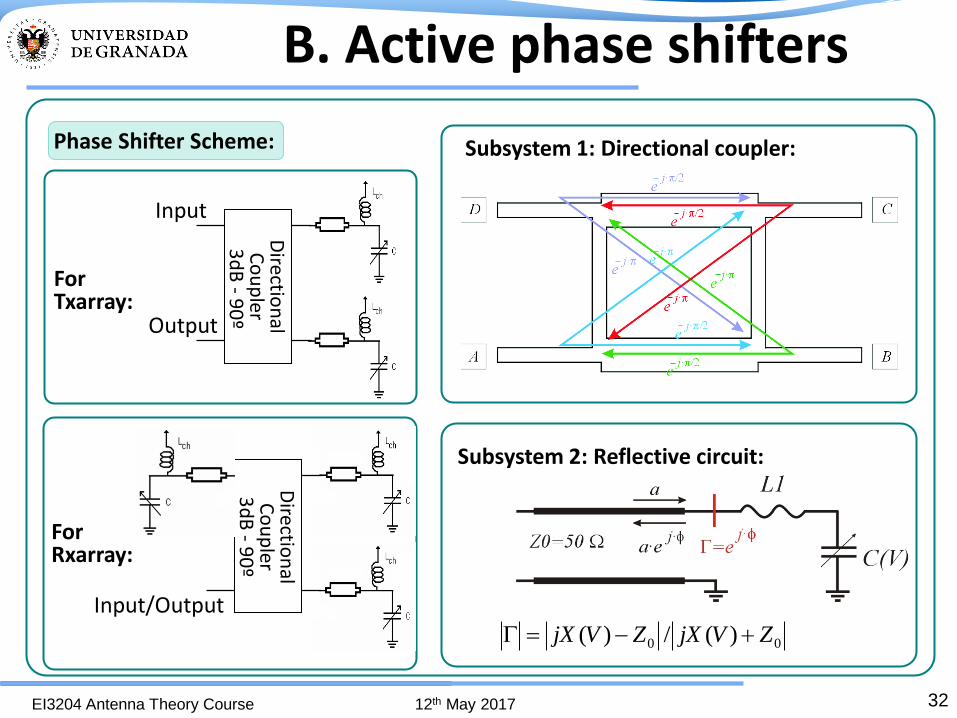
Phase Shifter Scheme:
Subsystem 1: Directional coupler:
Subsystem 2: Reflective circuit:
00 )(/)( ZVjXZVjX
B. Active phase shifters
Directio
nal
Co
up
ler 3
dB
- 90
º
Input
Output
Directio
nal
Co
up
ler 3
dB
- 90
º
Input/Output
For Txarray:
For Rxarray:

33 EI3204 Antenna Theory Course 12th May 2017
Phase Shifter Design: initial element design
4 port 3dB/90º coupler: Reflective LC circuits:
B. Active phase shifters

34 EI3204 Antenna Theory Course 12th May 2017
P1 (in) P2 (out 90º)
P3 (out 180º)P4 (isolated)
P(in/out)
L
C
L
C
L
C
Hybrid couplerReflective circuit
Reflective circuitReflective circuit
way 1way 2way 3way 4
B. Active phase shifters
working scheme
For Linearly Polarized Rxarrays:

35 EI3204 Antenna Theory Course 12th May 2017
Phase Shifter Design: LP integrated design
Amplitude: Phase:
B. Active phase shifters
printed Lprinted L
printed Lvaractor
varactorvaractor
hybridcoupler
reflectivecircuits
reflectivecircuit
via transition groundplane
substrate
coaxial feeding port(input/output)
11 11.2 11.4 11.6 11.8 12 12.2 12.4 12.6 12.8 13
-600
-400
-200
0
200
Freq [GHz]
S11 [
deg]
0.13pF
0.23pF
0.39pF
0.65pF
0.82pF
1.16pF
1.51pF
2.2pF
11 11.2 11.4 11.6 11.8 12 12.2 12.4 12.6 12.8 13-5
-4
-3
-2
-1
0
Freq [GHz]
S11 [
dB
]
0.13pF
0.23pF
0.39pF
0.65pF
0.82pF
1.16pF
1.51pF
2.2pF
For Linearly Polarized Rxarrays:

36 EI3204 Antenna Theory Course 12th May 2017
LP prototype manufacturing details
For Linearly Polarized Rxarrays:
B. Active phase shifters

37 EI3204 Antenna Theory Course 12th May 2017
Amplitude: Phase:
11 11.2 11.4 11.6 11.8 12 12.2 12.4 12.6 12.8 13-5
-4
-3
-2
-1
0
Freq [GHz]
S11 [
dB
]
0v
2v
4v
6v
8v
10v
12v
14v
16v
11 11.2 11.4 11.6 11.8 12 12.2 12.4 12.6 12.8 13-600
-500
-400
-300
-200
-100
0
Freq [GHz]
S11 [
deg]
0v
2v
4v
6v
8v
10v
12v
14v
16v
Phase Shifter: LP integrated prototype
For Linearly Polarized Rxarrays:
B. Active phase shifters
38 EI3204 Antenna Theory Course 12th May 2017
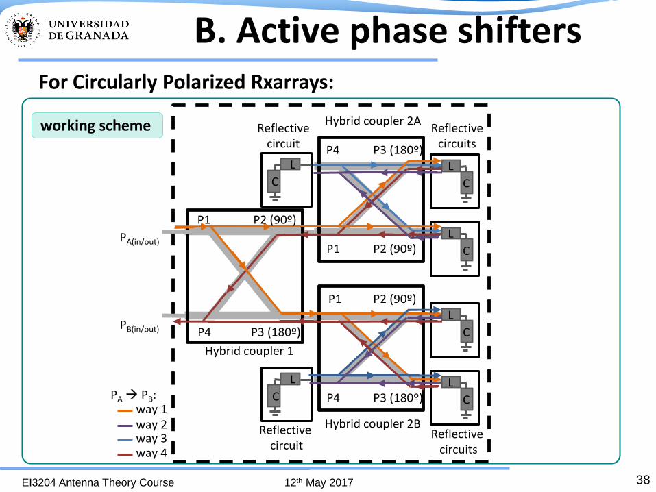
For Circularly Polarized Rxarrays:
PA(in/out)L
C
P4 P3 (180º)
P2 (90º)P1
L
C
Hybrid coupler 2AReflective
circuits
way 1way 2way 3way 4
L
C
L
C
Reflectivecircuit
P1
P4
Hybrid coupler 1
P2 (90º)
L
C
P1 P2 (90º)
P3 (180º)P4
L
C
Hybrid coupler 2BReflective
circuits
PB(in/out)
PA PB:
Reflectivecircuit
P3 (180º)
B. Active phase shifters
working scheme

39 EI3204 Antenna Theory Course 12th May 2017
Amplitude:
Phase:
11.5 12 12.5 13 13.5-1000
-800
-600
-400
-200
S12 [deg]
Freq [GHz]
0.13pF
0.23pF
0.39pF
0.65pF
0.82pF
1.16pF
1.51pF
2.2pF
460º
11.5 12 12.5 13 13.5-5
-4
-3
-2
-1
0
S12 [dB
]
Freq [GHz]
0.13pF
0.23pF
0.39pF
0.65pF
0.82pF
1.16pF
1.51pF
2.2pF
B. Active phase shifters
Phase Shifter Design: CP integrated design
For Circularly Polarized Rxarrays:

40 EI3204 Antenna Theory Course 12th May 2017
B. Active phase shifters
CP prototype manufacturing details
For Circularly Polarized Rxarrays:

41 EI3204 Antenna Theory Course 12th May 2017
Amplitude: Phase:
11.5 12 12.5 13 13.5-1000
-800
-600
-400
-200
S12 [deg]
Freq [GHz]
0v 2v 4v 6v 8v 10v 12v 14v 16v
370º
0 4 8 12 16-800
-650
-500
-350
S12 [
deg]
Volts
12.5 GHz
11.5 12 12.5 13 13.5-5
-4
-3
-2
-1
0
S12 [dB
]
Freq [GHz]
0v 2v 4v 6v 8v 10v 12v 14v 16v
Phase Shifter: CP integrated prototype
For Circularly Polarized Rxarrays:
B. Active phase shifters

42 EI3204 Antenna Theory Course 12th May 2017
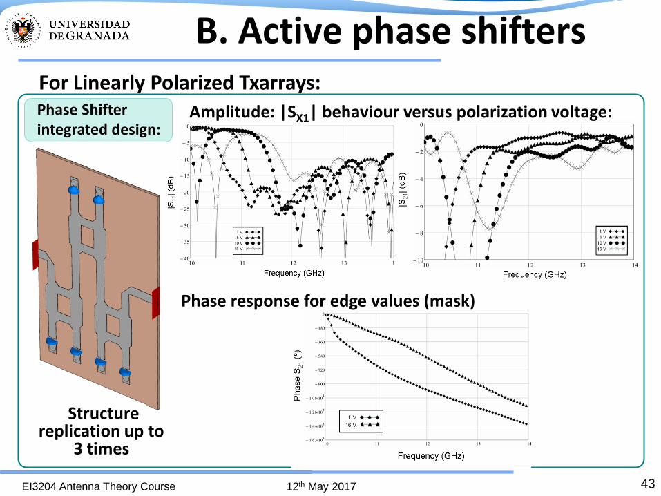
For Linearly Polarized Txarrays:
B. Active phase shifters
working scheme
43 EI3204 Antenna Theory Course 12th May 2017
Amplitude: |SX1| behaviour versus polarization voltage:
Structure replication up to
3 times
Phase response for edge values (mask)
Phase Shifter integrated design:
For Linearly Polarized Txarrays:
B. Active phase shifters

44 EI3204 Antenna Theory Course 12th May 2017
B. Active phase shifters
Prototype manufacturing details
For Linearly Polarized Txarrays:

45 EI3204 Antenna Theory Course 12th May 2017
Varactor
Inductive Line
Control circuit connection
Output Port
Input Port Coax. to microstrip transition
Z0Ω Transmission Line
Hybrid Circuit
Holes to Ground Plane
GND Connection
S21 Phase:
B. Active phase shifters
Phase Shifter measuring results:
For Linearly Polarized Txarrays:
Amplitude: |SX1| behaviour versus polarization voltage:
46 EI3204 Antenna Theory Course 12th May 2017
5. Example of reconfigurable device: Electronically Reconfigurable
Transmitarray

47 EI3204 Antenna Theory Course 12th May 2017
Electronically Reconfigurable Txarray
Transmitarray Scheme: Geometry Applied:
Patch grouping by means of bidirectional distribution networks.
•12 GHz, BW >0.7 GHz, LP
•Feeding corrugated horn
•6x6 element array. 0,7λ0 grid.
•360º range phase shifters.
•2x2 patch groups.
Constituting elements:
Stacked patches: Phase shifters:
Distribution networks: 90º transitions:
48 EI3204 Antenna Theory Course 12th May 2017
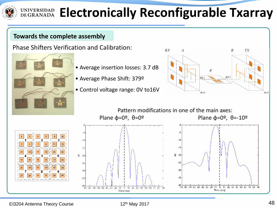
• Average insertion losses: 3.7 dB
• Average Phase Shift: 379º
• Control voltage range: 0V to16V
Towards the complete assembly
Phase Shifters Verification and Calibration:
Pattern modifications in one of the main axes: Plane φ=0º, θ=0º Plane φ=0º, θ=-10º
Electronically Reconfigurable Txarray

49 EI3204 Antenna Theory Course 12th May 2017
Shifters integration Integration in ground plane
• Two radiating interfaces. • 72 radiating elements. •18 distribution networks. • 9 complete phase shifters.
Complete Prototype:
Transmitarray assembly:
Patch layers
Radiating interface
Detail of inner zone Distribution networks
Transmitarray core
Complete electronically reconfigurable Txarray assembled
Electronically Reconfigurable Txarray

50 EI3204 Antenna Theory Course 12th May 2017
Prototype Measurement:
•Pattern 1: only phase error correction (all with 0V control voltage). •Pattern 2: phase error correction and reconfiguration of radiation pattern in one of the main axes, applying a 9 degrees tilt.
Theoretical radiation pattern Measured Radiation pattern
For prototype validation, two configurations:
Pattern 1: only phase error correction (all shifters with 0V control voltage).
3D measured radiation pattern 2D measured radiation pattern
Measured Gain: 16.05 dBi. Reduction due to spillover (accepted horn power 60%=-2.2 dB) and shifter insertion losses (3dB mean value in this configuration.
Electronically Reconfigurable Txarray

51 EI3204 Antenna Theory Course 12th May 2017
Prototype Measurement:
•Pattern 1: only phase error correction •Pattern 2: phase error correction and reconfiguration of radiation pattern in one of the main axes, 9 degrees tilt.
Theoretical radiation pattern Measured Radiation pattern
For prototype validation, two configurations :
Pattern 2: Phase error correction and 9º tilt in one main axis
3D measured radiation pattern 2D measured radiation pattern
Measured Gain: 15.1 dBi. Reduction due to spillover (accepted horn power 60%=-2.2 dB) and shifter insertion losses (4dB mean value in this configuration).
Electronically Reconfigurable Txarray

52 EI3204 Antenna Theory Course 12th May 2017
Thanks for your attention!

I. MIMO antenna
performance parameters
EI3204 Antenna Theory Course 8-10 May 2017
“Transmitarrays, reflectarrays and
phase shifters for wireless
communication systems”
Pablo Padilla de la Torre
Universidad de Granada
![RADAVANT SCIENTIFICCONTRIBUTIONSOFTHE RADAVANTPROJECT(EN) · 2021. 1. 20. · Transmitarray [5]–[7] is the conventional name given to structures that can modify the original radiation](https://img.pdfslide.us/doc/110x75/6139ad6e0051793c8c009e06/radavant-scientificcontributionsofthe-radavantprojecten-2021-1-20-transmitarray.jpg)


![REFLECTARRAYS FOR BEAM SQUINT COMPENSATION OF ORTHOGONALLY POLARIZED TX/RX OFFSET ANTENNA SYSTEMS - TICRA - Reflector … · reflector [8]. In addition to contoured beams, curved](https://img.pdfslide.us/doc/110x75/600edc7fc26d3745fd09e5c5/reflectarrays-for-beam-squint-compensation-of-orthogonally-polarized-txrx-offset.jpg)