Embed Size (px)
Citation preview
Transmission of Digital Data: Interfaces and Modems
NETE 0510
Dr.Apichan Kanjanavapastit
Digital Data Transmission
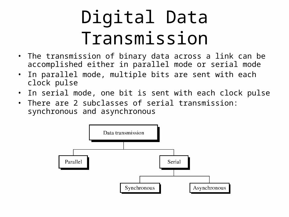
• The transmission of binary data across a link can be accomplished either in parallel mode or serial mode
• In parallel mode, multiple bits are sent with each clock pulse• In serial mode, one bit is sent with each clock pulse• There are 2 subclasses of serial transmission: synchronous and
asynchronous
Parallel Transmission
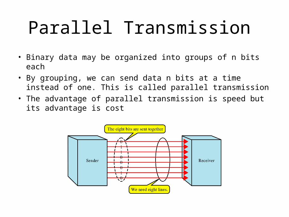
• Binary data may be organized into groups of n bits each• By grouping, we can send data n bits at a time instead of
one. This is called parallel transmission• The advantage of parallel transmission is speed but its
advantage is cost
Serial Transmission
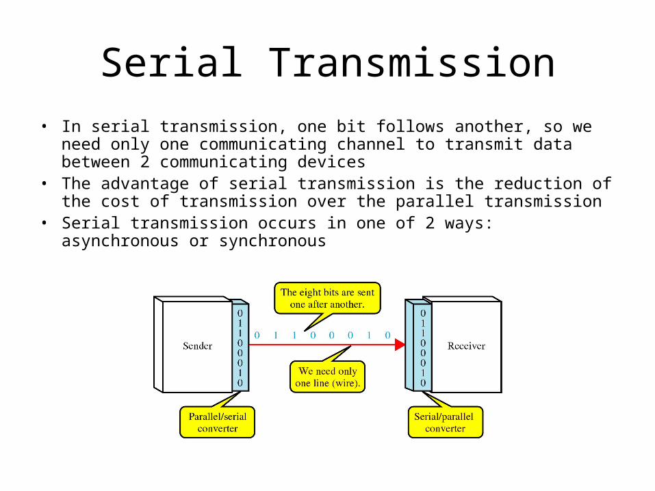
• In serial transmission, one bit follows another, so we need only one communicating channel to transmit data between 2 communicating devices
• The advantage of serial transmission is the reduction of the cost of transmission over the parallel transmission
• Serial transmission occurs in one of 2 ways: asynchronous or synchronous
Asynchronous Transmission
• In asynchronous transmission, the timing of a signal is unimportant
• Information is received and translated by agreed-upon patterns
• Patterns are based on grouping the bit stream into bytes
• The sending system handles each group independently, relaying it to the link whenever ready, without regard to a timer
Asynchronous Transmission (cont.)
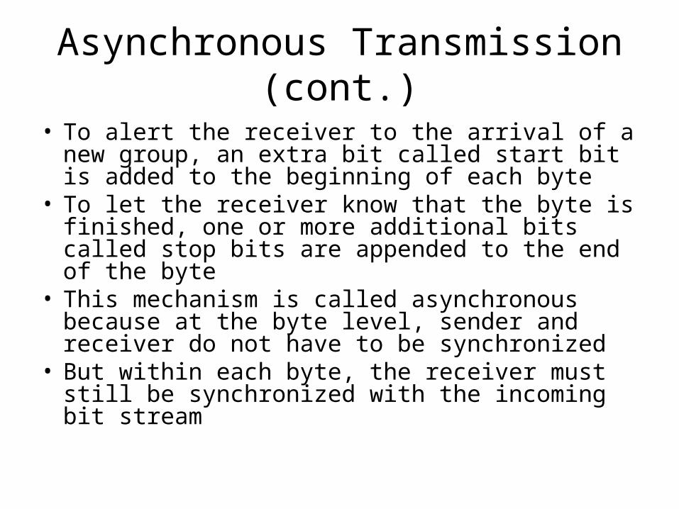
• To alert the receiver to the arrival of a new group, an extra bit called start bit is added to the beginning of each byte
• To let the receiver know that the byte is finished, one or more additional bits called stop bits are appended to the end of the byte
• This mechanism is called asynchronous because at the byte level, sender and receiver do not have to be synchronized
• But within each byte, the receiver must still be synchronized with the incoming bit stream
Asynchronous Transmission (cont.)
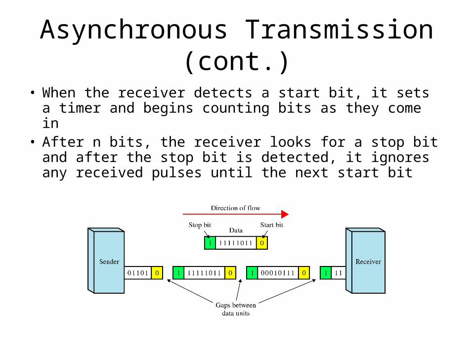
• When the receiver detects a start bit, it sets a timer and begins counting bits as they come in
• After n bits, the receiver looks for a stop bit and after the stop bit is detected, it ignores any received pulses until the next start bit
Synchronous Transmission
• In synchronous transmission, the bit stream is combined into longer frames which may contains multiple bytes
• Each byte is introduced onto the transmission link without a gap between it and the next one
• It is the responsibility of the receiver to reconstruct the information
Synchronous Transmission (cont.)
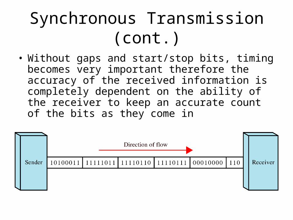
• Without gaps and start/stop bits, timing becomes very important therefore the accuracy of the received information is completely dependent on the ability of the receiver to keep an accurate count of the bits as they come in
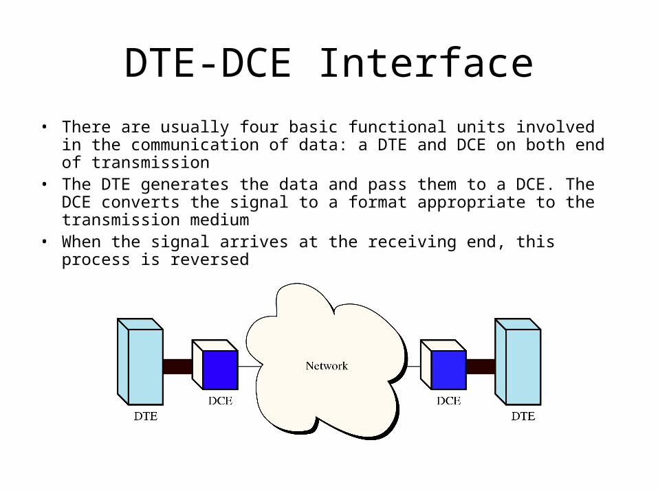
DTE-DCE Interface• There are usually four basic functional units involved in the
communication of data: a DTE and DCE on both end of transmission• The DTE generates the data and pass them to a DCE. The DCE
converts the signal to a format appropriate to the transmission medium• When the signal arrives at the receiving end, this process is reversed
Data Terminal Equipment (DTE)
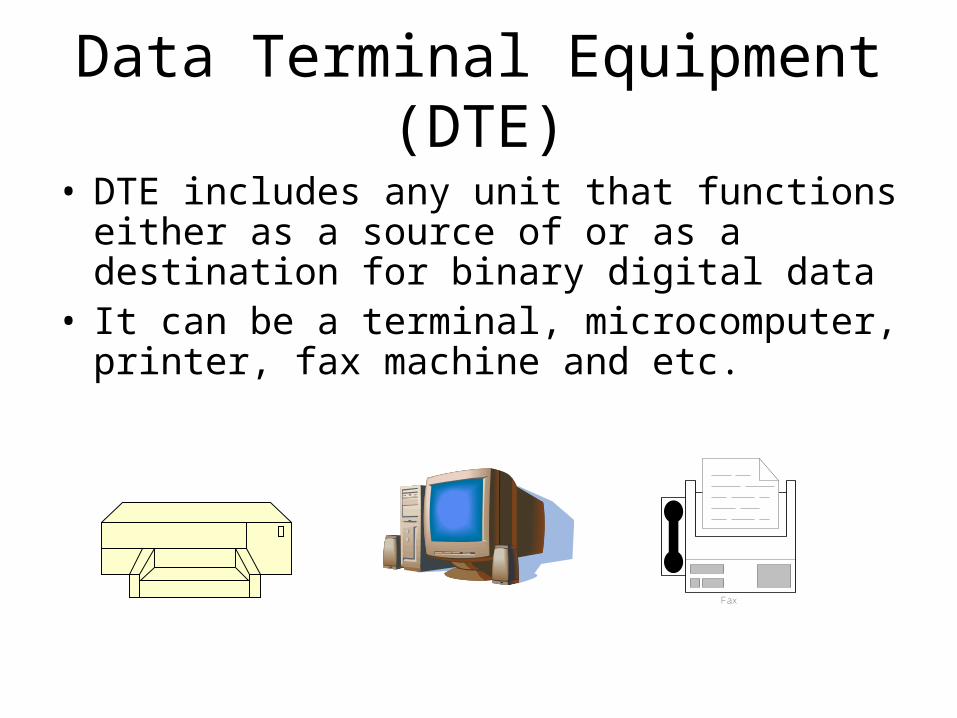
• DTE includes any unit that functions either as a source of or as a destination for binary digital data
• It can be a terminal, microcomputer, printer, fax machine and etc.
Fax
Data Circuit-Terminating Equipment (DCE)
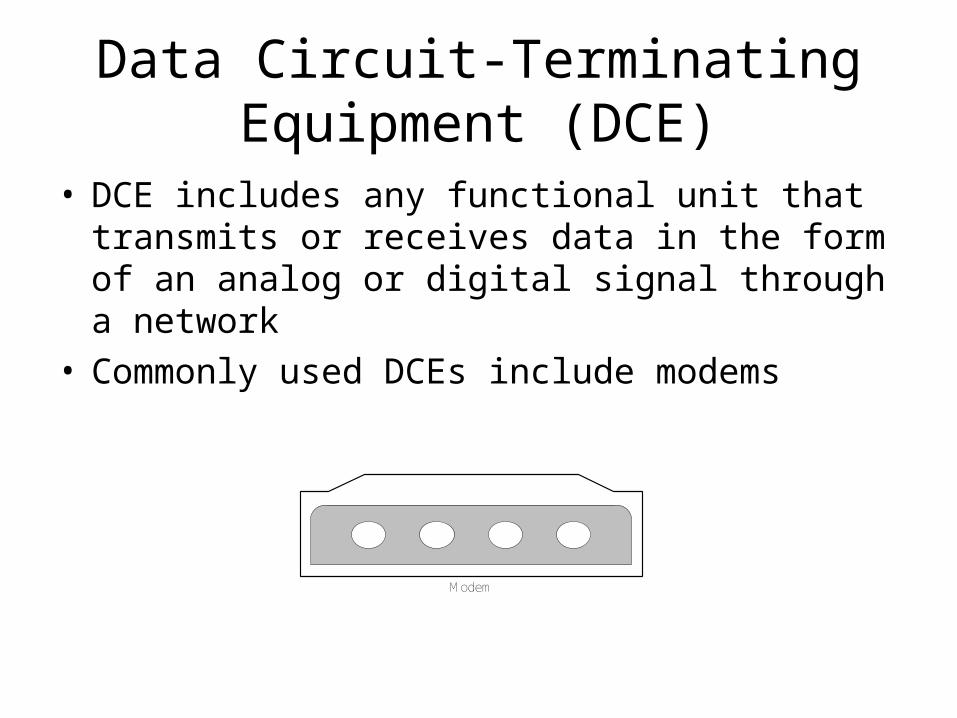
• DCE includes any functional unit that transmits or receives data in the form of an analog or digital signal through a network
• Commonly used DCEs include modems
Modem
DTE-DCE Interface Standard
• Many standards have been developed to define the connection between a DTE and a DCE
• Each standard provides a model for the mechanical, electrical, and functional characteristics of the connection
• The most active organizations defining the interface standard are the Electronic Industries Association (EIA) and the International Telecommunication Union-Telecommunication Standards Committee (ITU-T)
DTE-DCE Interface Standard (cont.)
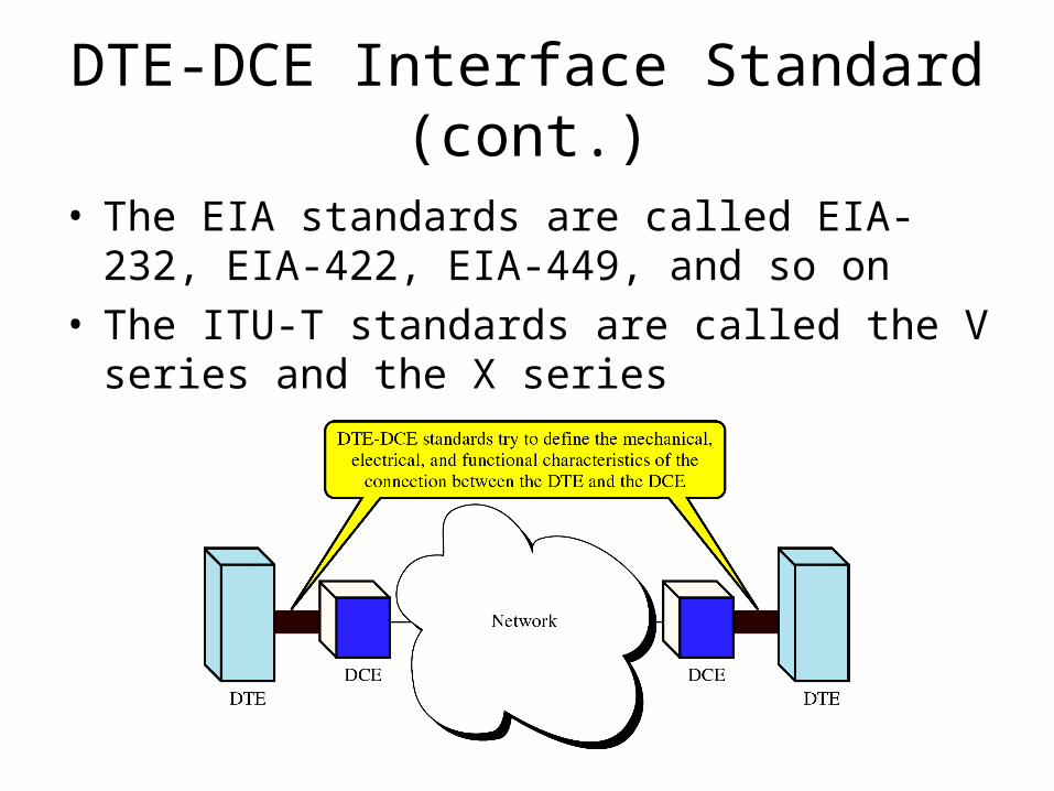
• The EIA standards are called EIA-232, EIA-422, EIA-449, and so on
• The ITU-T standards are called the V series and the X series
EIA-232 Interface
• Originally issued in 1962 as the RS-232 standard (recommended standard)
• The most recent version, EIA-232-D, defines not only the type of connectors to be used but also the specific cable and plugs and the functionality of each pin
EIA-232 Mechanical specification
• The EIA-232 defines the interfaces as a 25-wire cable with a male and a female DB-25 pin connection attached to either end. The length of the cable may not exceed 15 meters
• A DB-25 connector is a plug with 25 pins, each of which is attached to a single wire with a specific function. However, fewer are actually used in current practice
• Another implementation of EIA-232 uses a 9-wire cable with a mail and a female DB-9 pin connector attached to either end
• 9-pin connector is more commonly found in PCs but it covers signals for asynchronous serial communication only
• Male connector is used on DTE and female connector is used on DCE
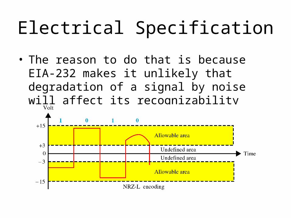
Electrical Specification
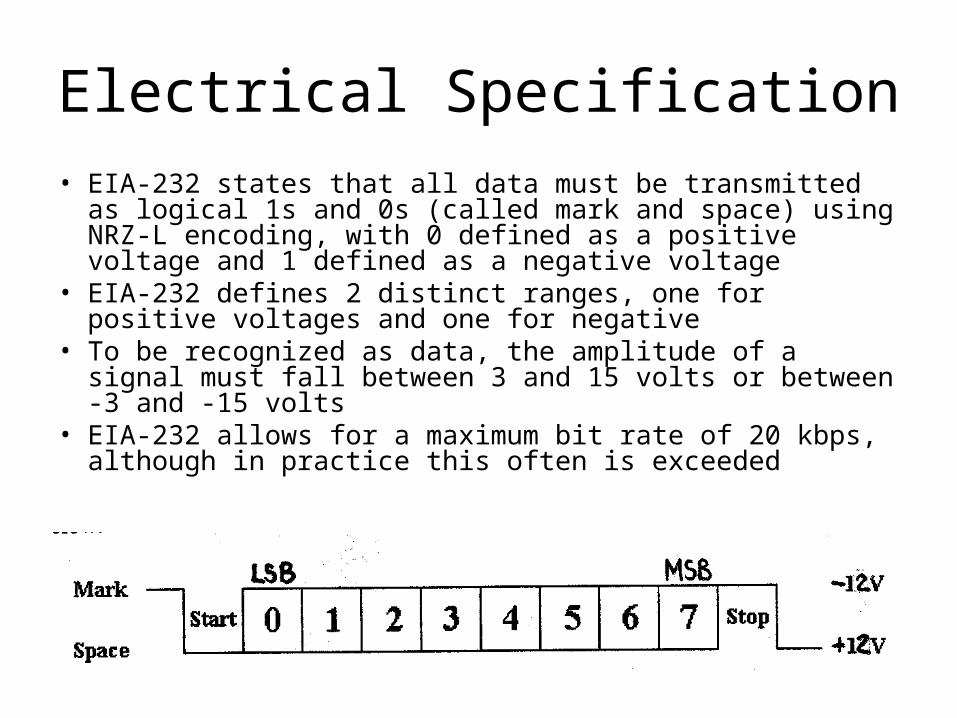
• EIA-232 states that all data must be transmitted as logical 1s and 0s (called mark and space) using NRZ-L encoding, with 0 defined as a positive voltage and 1 defined as a negative voltage
• EIA-232 defines 2 distinct ranges, one for positive voltages and one for negative
• To be recognized as data, the amplitude of a signal must fall between 3 and 15 volts or between -3 and -15 volts
• EIA-232 allows for a maximum bit rate of 20 kbps, although in practice this often is exceeded
Electrical Specification
• The reason to do that is because EIA-232 makes it unlikely that degradation of a signal by noise will affect its recognizability
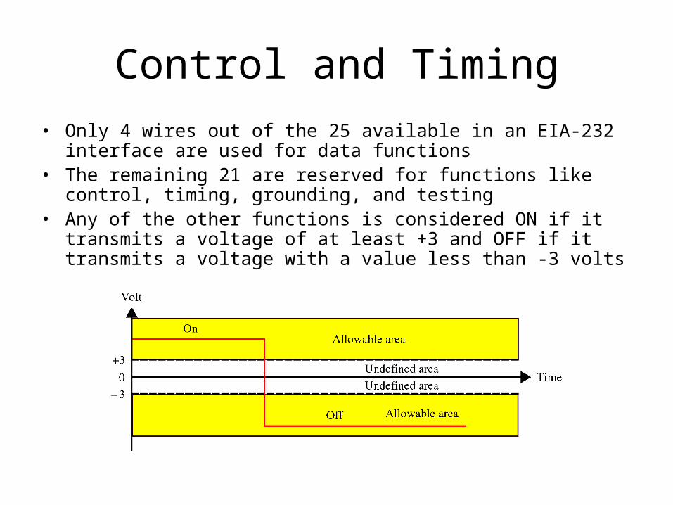
Control and Timing
• Only 4 wires out of the 25 available in an EIA-232 interface are used for data functions
• The remaining 21 are reserved for functions like control, timing, grounding, and testing
• Any of the other functions is considered ON if it transmits a voltage of at least +3 and OFF if it transmits a voltage with a value less than -3 volts
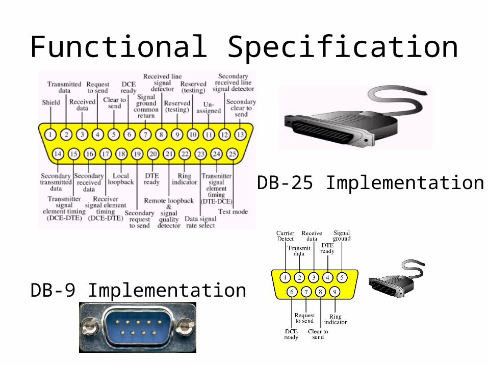
Functional Specification
DB-25 Implementation
DB-9 Implementation
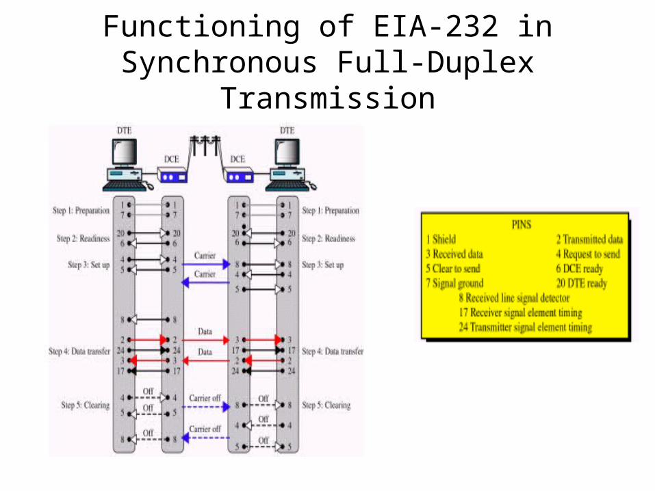
Functioning of EIA-232 in Synchronous Full-Duplex Transmission
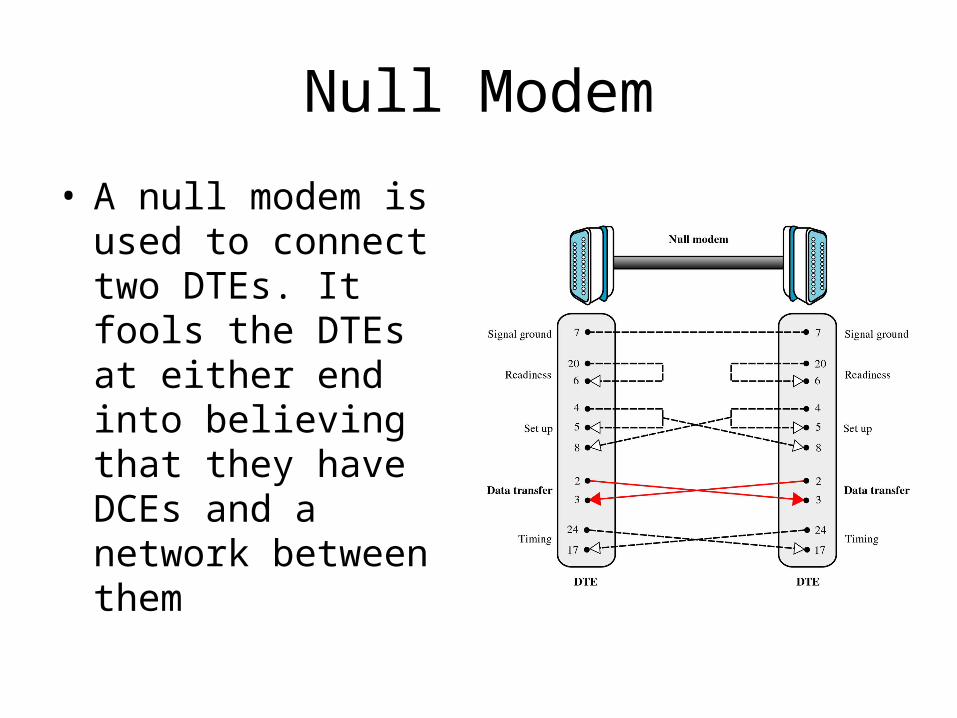
Null Modem
• A null modem is used to connect two DTEs. It fools the DTEs at either end into believing that they have DCEs and a network between them
Flow Control
• Means to ask the transmitter to stop/resume sending in data
• Required when:– DTE to DCE speed > DCE to DCE speed
(e.g. terminal speed = 115.2kbps and line speed = 33.6kbps, in order to benefit from modem’s data compression protocol)
• without flow control, the buffer within modem will overflow – sooner or later
– the receiving end takes time to process the data and thus cannot be always ready to receive
Hardware Flow Control
• RTS/CTS– the transmitting end activates RTS to inform
the receiving end that it has data to send– if the receiving end is ready to receive, it
activates CTS– normally used between computer and modem
• computer is always ready to receive data but modem is not, because terminal speed > link speed
Software Flow Control
• Xon/Xoff– when the buffer within the receiving end is nearly full,
Xoff is sent to the transmitting end to ask it to stop– when data have been processed by the receiving end
and the buffer has space again, Xon is sent to the transmitting end to notify it to resume
– advantage: only three wires are required (TD, RD and GND)
– disadvantage: confusion arises when the transmitted data (e.g. a graphics file) contains a byte equal to 13H (Xoff)
Breakout Box
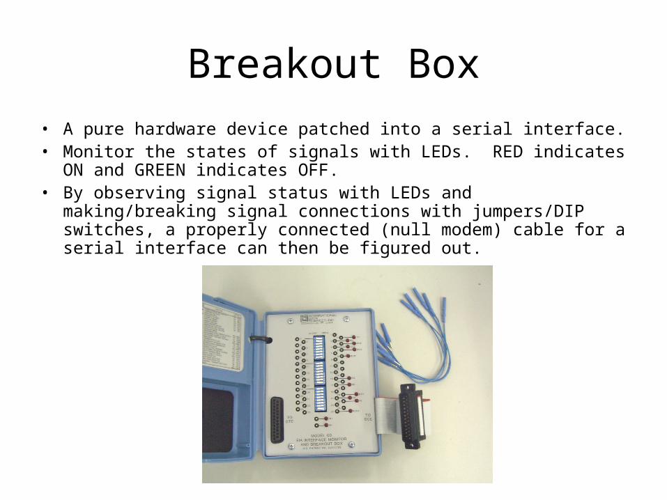
• A pure hardware device patched into a serial interface.• Monitor the states of signals with LEDs. RED indicates ON and
GREEN indicates OFF.• By observing signal status with LEDs and making/breaking signal
connections with jumpers/DIP switches, a properly connected (null modem) cable for a serial interface can then be figured out.
Modem
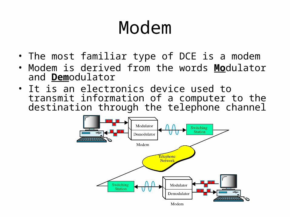
• The most familiar type of DCE is a modem• Modem is derived from the words Modulator and Demodulator
• It is an electronics device used to transmit information of a computer to the destination through the telephone channel
Telephone Bandwidth
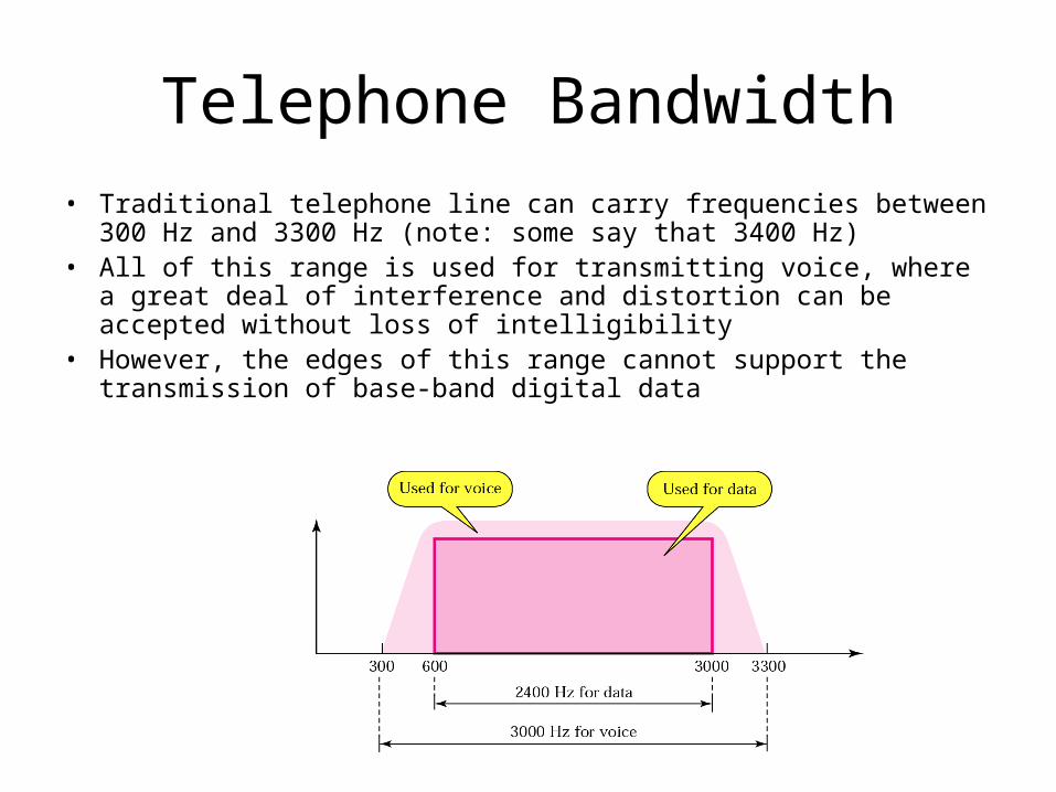
• Traditional telephone line can carry frequencies between 300 Hz and 3300 Hz (note: some say that 3400 Hz)
• All of this range is used for transmitting voice, where a great deal of interference and distortion can be accepted without loss of intelligibility
• However, the edges of this range cannot support the transmission of base-band digital data
Bell Modems
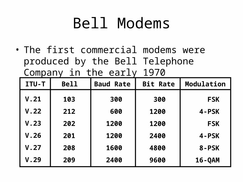
• The first commercial modems were produced by the Bell Telephone Company in the early 1970
ITU-T Bell Baud Rate Bit Rate Modulation
V.21
V.22
V.23
V.26
V.27
V.29
103
212
202
201
208
209
300
600
1200
1200
1600
2400
300
1200
1200
2400
4800
9600
FSK
4-PSK
FSK
4-PSK
8-PSK
16-QAM
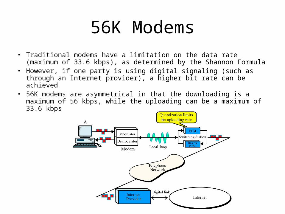
56K Modems
• Traditional modems have a limitation on the data rate (maximum of 33.6 kbps), as determined by the Shannon Formula
• However, if one party is using digital signaling (such as through an Internet provider), a higher bit rate can be achieved
• 56K modems are asymmetrical in that the downloading is a maximum of 56 kbps, while the uploading can be a maximum of 33.6 kbps
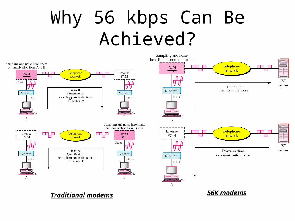
Why 56 kbps Can Be Achieved?
Traditional modems 56K modems
Why Only 56 kbps?
• Switching stations use PCM and inverse PCM, sampling at 8000 samples per second with 128 different levels (7 bits per sample)
• This results in a 56 kbps (8000*7 = 56,000) data rate at the switching station