Embed Size (px)
Citation preview
Transmission Media
Dr. Indranil Sen Gupta Transmission Media Slide 1
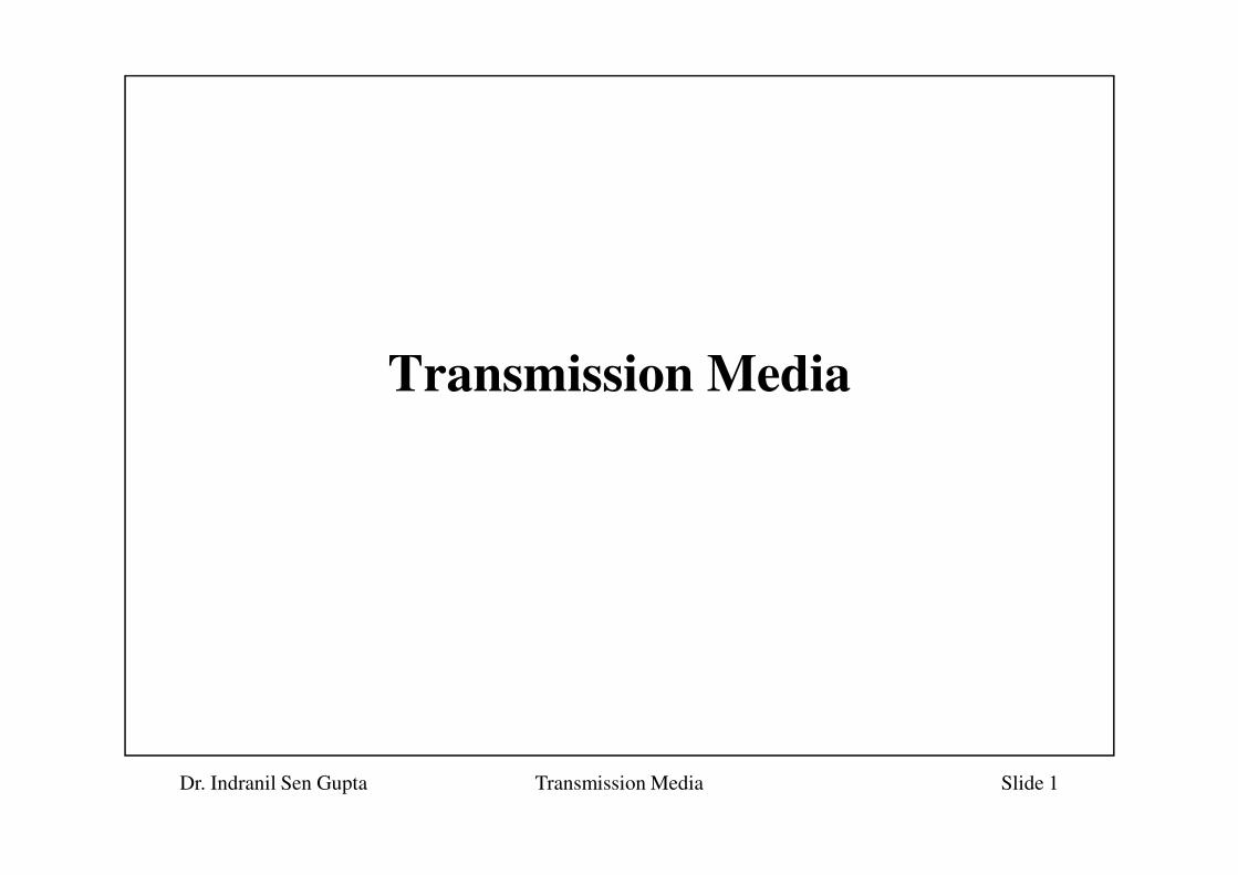
Introduction
• Physical path between transmitter and receiver in a
data transmission system.
• May be classified into two types:
Dr. Indranil Sen Gupta Transmission Media Slide 2
– Guided:- waves are guided along a solid medium, such
as copper twisted pair, copper coaxial cable, or optical
fiber.
– Unguided:- provides a means for transmitting electro-
magnetic signals but do not guide them.
• Wireless transmission

Contd.
• Characteristics and quality of data transmission are
determined by medium and signal characteristics.
– For guided media, the medium is more important in determining the
limitations of transmission.
Dr. Indranil Sen Gupta Transmission Media Slide 3
– For unguided media, the bandwidth of the signal produced by the
transmitting antenna is more important than the medium.
• Signals at lower frequencies are omnidirectional
– propagate in all directions
• For higher frequencies, focussing the signals into a directional beam is
possible.
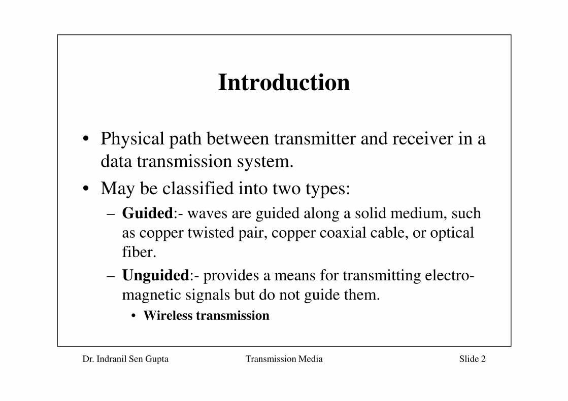
Guided Transmission Media
• Transmission capacity depends critically on the
distance, and whether the medium is point-to-point
or multipoint (e.g. LAN).
• Point-to-point transmission performances:
Dr. Indranil Sen Gupta Transmission Media Slide 4
• Point-to-point transmission performances:
Transmission
Medium
Total Data
Rate
Bandwidth Repeater
Spacing
Twisted pair 4 Mbps 3 MHz 2-10 Km
Coaxial cable 500 Mbps 350 MHz 1-10 Km
Optical fiber 2 Gbps 2 GHz 10-100 Km
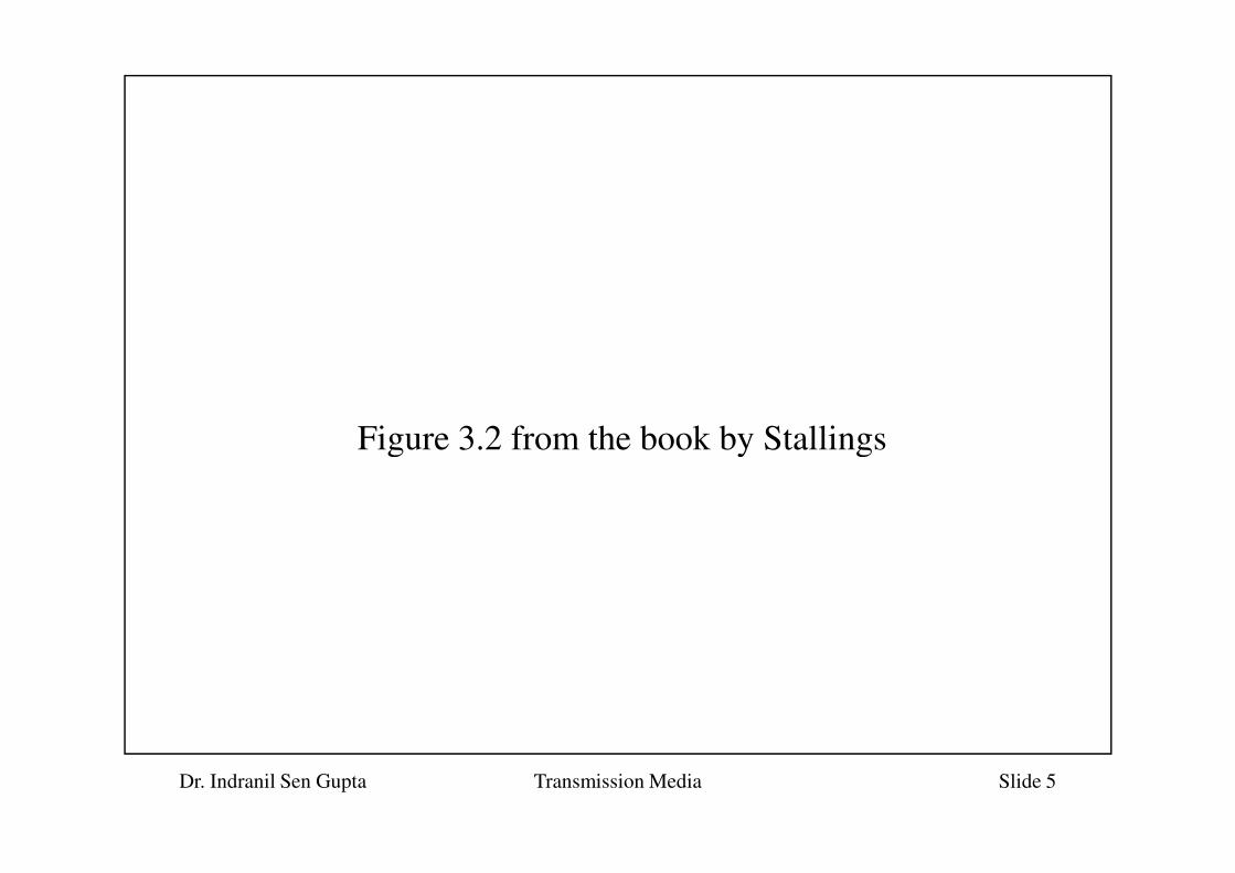
Figure 3.2 from the book by Stallings
Dr. Indranil Sen Gupta Transmission Media Slide 5
Figure 3.2 from the book by Stallings
Guided Media: Twisted Pair
• A twisted pair consists of two insulated copper wires
arranged in a regular spiral pattern.
– Twisting decreases the crosstalk interference between adjacent pairs
in a cable.
Dr. Indranil Sen Gupta Transmission Media Slide 6
– Typically, a number of pairs are bundled together into a cable by
wrapping them in a tough protective sheath.
• Most common transmission media for both analog and
digital signals.
– Telephone network
– Connecting computers in a LAN (upto 100 Mbps)
Twisted Pair (contd.)
• Two common types:
– Unshielded Twisted Pair (UTP)
• ordinary telephone wire
• subject to external electromagnetic interference
• Two commonly used categories (vide Electronic Industries
Association standard EIA-568)
Dr. Indranil Sen Gupta Transmission Media Slide 7
Association standard EIA-568)
– Category 3: upto 16 MHz
– Category 5: upto 100 MHz
• A key difference is the number of twists in the cable per
unit distance.
– Cat-3 ==> 3-4 twists per foot; Cat-5 ==> 3-4 twists per inch
– Tighter twisting of Cat-5 provides much better performance, but
also increases the cost.
Guided Media: Coaxial Cable
• Consists of a hollow outer cylindrical conductor that
surrounds a single inner wire conductor.
– The inner conductor is held in place by either regularly spaced
insulating rings or a solid dielectric material.
– The outer conductor is covered with a jacket or shield.
Dr. Indranil Sen Gupta Transmission Media Slide 8
• Due to its shielding, coaxial cables are much less
susceptible to interference or crosstalk than twisted pair.
• Used in a variety of applications:
– Television distribution (cable TV)
– Long-distance telephone transmission (10,000 voice channels per
cable)
– Local Area Networks

Guided Media: Optical Fiber
• An optical fiber is a thin (2-125 micrometer), flexible
medium capable of conducting an optical ray.
– Made of ultrapure fused silica, glass fiber or even plastic.
• It has a cylindrical shape and consists of three concentric
Dr. Indranil Sen Gupta Transmission Media Slide 9
• It has a cylindrical shape and consists of three concentric
sections: the core, the cladding, and the jacket.
– The core consists of one or more very thin strands, or fibers, made
of glass or plastic.
– The cladding is a glass or plastic coating that has optical properties
different from that of the core.
– The jacket surrounds one or a bundle of cladded fibers.
Optical Fiber (contd.)
• Main advantages of optical fiber:
– Greater capacity (2Gbps over tens of kilometers)
– Smaller size and lighter weight
– Lower attenuation
Dr. Indranil Sen Gupta Transmission Media Slide 10
– Lower attenuation
– Electromagnetic isolation
– Greater repeater spacing
• Long-haul fiber transmission is becoming increasingly
common in the telephone network.
– About 900 miles with 20,000 to 60,000 voice channels

Optical Fiber (contd.)
• Optical fiber systems operate in the range of 10^14 to
10^15 Hz.
– Light from a source enters the cylindrical glass or plastic core.
– Rays at shallow angles are reflected and propagated along the
fiber; other rays are absorbed by the surrounding material.
• Three types of communication:
Dr. Indranil Sen Gupta Transmission Media Slide 11
• Three types of communication:
– Multimode: Refers to the variety of angles that will reflect.
Multiple propagation path exists, signal elements spread out in
time, and hence limits the data rate.
– Single-mode:- When the fiber code radius is reduced, fewer angles
will reflect. By reducing the radius of the core to the order of a
wavelength, only a single angle or mode can pass (the axial ray).
– Multimode graded index: By varying the refractive index of the
core, rays may be focussed more efficiently than multimode.
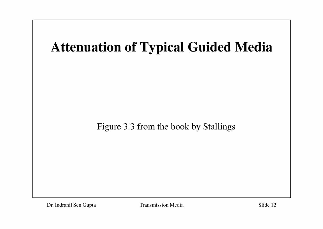
Attenuation of Typical Guided Media
Dr. Indranil Sen Gupta Transmission Media Slide 12
Figure 3.3 from the book by Stallings
Wireless Transmission
• Transmission and reception are achieved by means of
antenna.
– For transmission, the antenna radiated electromagnetic radiation in
the air.
Dr. Indranil Sen Gupta Transmission Media Slide 13
– For reception, the antenna picks up electromagnetic waves from the
surrounding medium.
• Basically two types of configuration:
– Transmitting antenna puts out a focussed electromagnetic beam.
• Transmitter & receiver must be carefully aligned.
– Transmitted signal spreads in all directions.
• Can be received by many antennas.

Contd.
• Three general ranges of frequencies:
– 2-40 GHz
• microwave frequencies
• highly directional beams are possible
Dr. Indranil Sen Gupta Transmission Media Slide 14
• suitable for point-to-point and satellite transmission
– 30 MHz - 1 GHz
• broadcast radio range
• suitable for omnidirectional applications
– 0.3 - 200 THz
• infrared range
• useful for point-to-point and multipoint applications within confined
areas, such as a single room.
Wireless: Terrestial Microwave
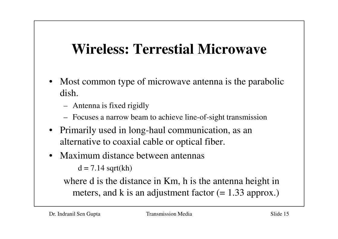
• Most common type of microwave antenna is the parabolic
dish.
– Antenna is fixed rigidly
– Focuses a narrow beam to achieve line-of-sight transmission
Dr. Indranil Sen Gupta Transmission Media Slide 15
– Focuses a narrow beam to achieve line-of-sight transmission
• Primarily used in long-haul communication, as an
alternative to coaxial cable or optical fiber.
• Maximum distance between antennas
d = 7.14 sqrt(kh)
where d is the distance in Km, h is the antenna height in
meters, and k is an adjustment factor (= 1.33 approx.)
Wireless: Satellite Microwave
• A communication satellite is basically a microwave relay
station.
– Used to link two or more earth stations.
– Satellite receives transmission on one frequency band (uplink),
Dr. Indranil Sen Gupta Transmission Media Slide 16
– Satellite receives transmission on one frequency band (uplink),
amplifies or repeats the signal, and transmits it on another frequency
(downlink).
– A single orbiting satellites operate on a number of frequency bands,
called transponders.
• Geostationary orbit
– often necessary for it to function effectively
– height of 35,784 Km

Satellite Communication
Configurations
Point-to-point linkBroadcast link
Dr. Indranil Sen Gupta Transmission Media Slide 17
Transmitter
Multiple
Receivers
Multiple
Receivers
Satellite (contd.)
• Two satellites using the same frequency band, if close
enough, will interfere with each other.
– Minimum 4 degrees spacing in the 4/6 GHz band.
– Minimum 3 degrees spacing in the 12/14 GHz band.
Dr. Indranil Sen Gupta Transmission Media Slide 18
– Minimum 3 degrees spacing in the 12/14 GHz band.
• Most important applications of satellite:
– Television distribution
– Long-distance telephone transmission
– Private business network (using VSATs).
Very Small Aperture Terminal
(VSAT)
• A relatively low-cost solution.
• A number of subscriber stations are equipped with low-cost
VSAT antennas.
– Using some protocol, these stations share a satellite channel for
Dr. Indranil Sen Gupta Transmission Media Slide 19
– Using some protocol, these stations share a satellite channel for
transmission to a hub station.
– The hub station can exchange messages with each of the subscribers
as well as relay messages between subscribers.
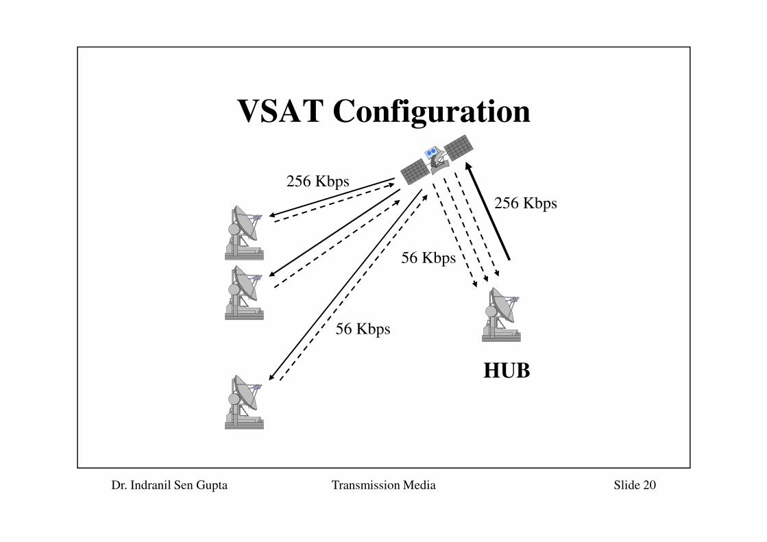
VSAT Configuration
256 Kbps
256 Kbps
56 Kbps
Dr. Indranil Sen Gupta Transmission Media Slide 20
56 Kbps
HUB

Wireless: Broadcast Radio
• Omnidirectional
• Covers VHF and part of UHF band
– 30 MHz -- 1 GHz
• Apart from FM radio as well as UHF and VHF TV, also
Dr. Indranil Sen Gupta Transmission Media Slide 21
• Apart from FM radio as well as UHF and VHF TV, also
used in data networking applications.

Wireless: Infrared
• Uses transceivers that modulate non-coherent infrared light.
• Must be in light of sight, either directly or via reflection
from a light-colored surface such as the ceiling of a room.
• Does not penetrate walls.
Dr. Indranil Sen Gupta Transmission Media Slide 22
• Does not penetrate walls.
• No frequency allocation issue.
– No licensing required.