Embed Size (px)
Citation preview

Faculdade de Engenharia
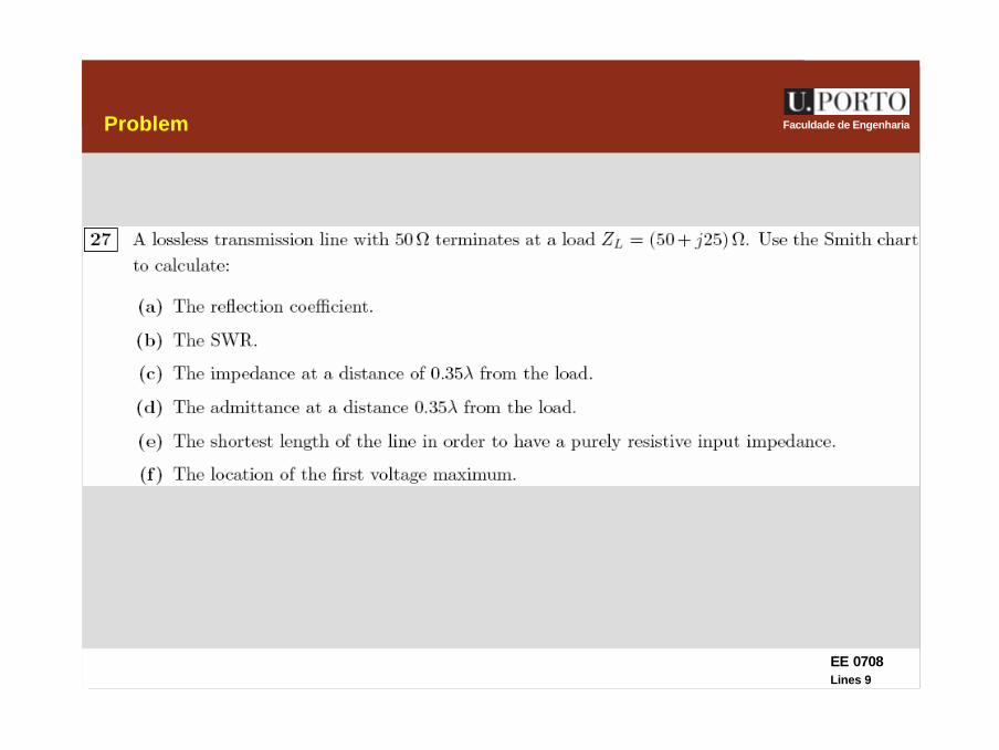
Transmission Lines
ELECTROMAGNETIC ENGINEERINGMAP – TELE 2007/2008

EE 0708Lines 2
Faculdade de EngenhariaLast week
general transmission line equations
propagation constant and characteristic impedance
finite transmission lines
reflection coefficient
stationary wave à voltage maxima and minima, SWR
transmission lines as circuit elements
the Smith chart
impedance and reflection coefficient determination
admittance
location of voltage and current maxima and minima
( )( )CjGLjR ωωγ ++=
CjGLjR
Zωω
++
=0
0
0
ZZZZ
L
LL +
−=Γ

EE 0708Lines 3
Faculdade de EngenhariaToday
the Smith chart
review
impedance matching
λ/4 transformer
reactive elements
single-stub
double-stub
transients
EE 0708Lines 4
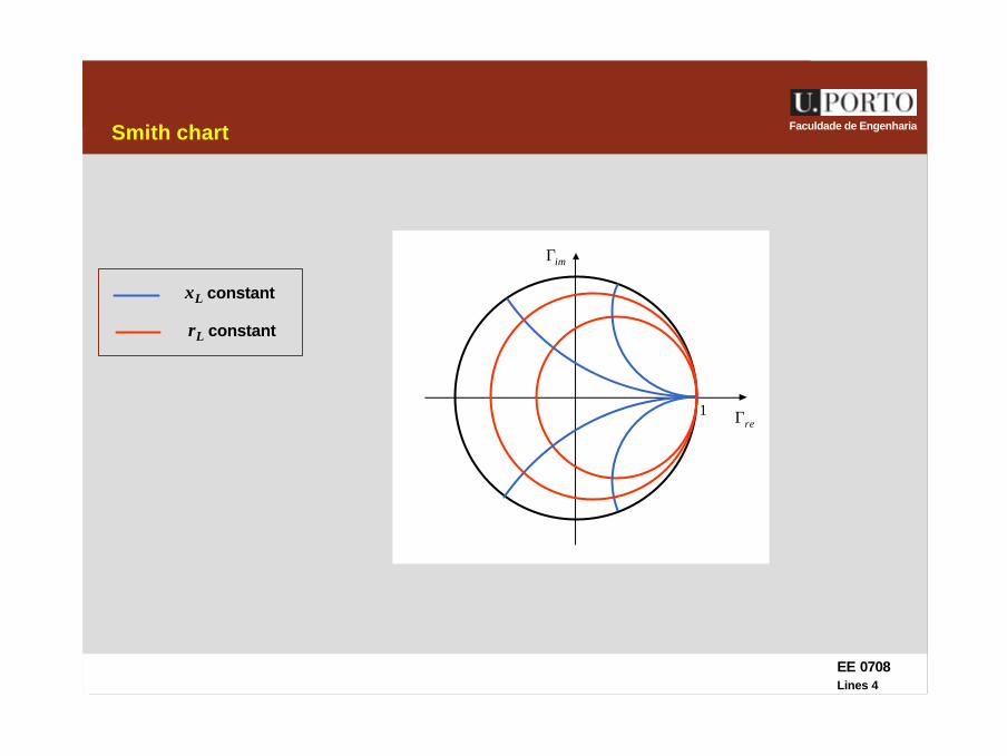
Faculdade de EngenhariaSmith chart
reΓ
imΓ
1
xL constant
rL constant
EE 0708Lines 5
Faculdade de Engenharia
Γθ
reΓ
imΓ
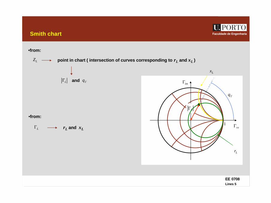
Smith chart
1
LΓ
LZ
•from:
point in chart ( intersection of curves corresponding to rL and xL )
ΓθandLΓ
rL and xL
Lx
Lr
LΓ
•from:

EE 0708Lines 6
Faculdade de EngenhariaInput impedance
1. draw the point corresponding to the normalized load impedance zL à point P1
2. draw the circle centered at the origin with radius OP1
3. draw the straight line from O to P1
4. draw the straight line from O that corresponds to a rotation of l toward the generator
5. intersection of this line with previous circle à point P2
6. obtain , where zin is read from P2
reΓ
imΓ
1
0ZzZ inin ⋅=
P1
P2
EE 0708Lines 7
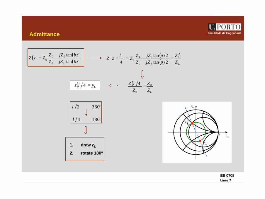
Faculdade de EngenhariaAdmittance
reΓ
imΓ
1
( ) ( )( )'tan
'tan'
0
00 zjZZ
zjZZZzZ
L
L
ββ
++
= ( )( ) LL
L
ZZ
jZZjZZ
ZzZ20
0
00 2tan
2tan4
' =++
=
=
ππλ
( )LZ
ZZ
Z 0
0
4=
λ( ) Lyz =4λ
º3602 ⇔λ
º1804 ⇔λ
1. draw zL
2. rotate 180º
Ly
Lz
EE 0708Lines 8
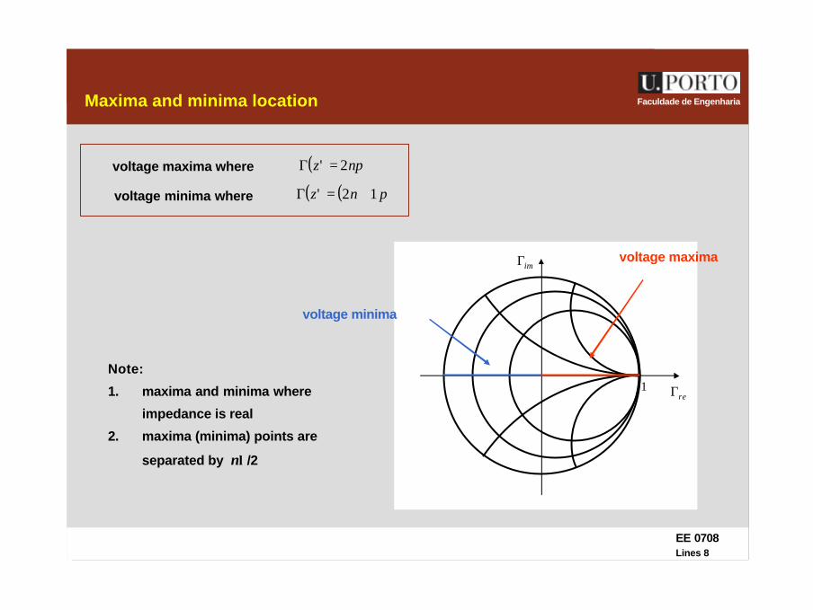
Faculdade de EngenhariaMaxima and minima location
reΓ
imΓ
1
voltage maxima where ( ) πnz 2' =Γ∠
voltage minima where ( ) ( )π12' +=Γ∠ nz
voltage maxima
voltage minima
Note:
1. maxima and minima where
impedance is real
2. maxima (minima) points are
separated by nλ/2
EE 0708Lines 9
Faculdade de EngenhariaProblem
EE 0708Lines 10
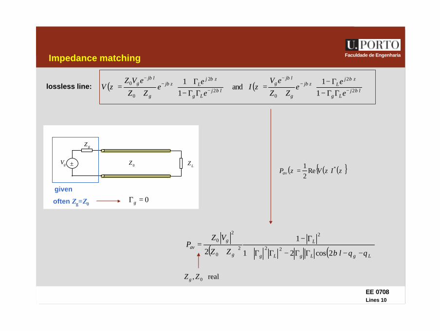
Faculdade de EngenhariaImpedance matching
lossless line: ( ) ( )
ΓΓ−Γ−
+=
ΓΓ−Γ+
+= −
−−
−−
−
ljLg
zjLzj
g
ljg
ljLg
zjLzj
g
ljg
ee
eZZ
eVzI
ee
eZZ
eVZzV β
ββ
β
β
ββ
β
2
2
02
2
0
0
11
and1
1
( ) ( ) ( ){ }zIzVzPav*Re
21
=
( ) ( )LgLgLg
L
g
gav
lZZ
VZP
θθβ −−ΓΓ−ΓΓ+
Γ−
+=
2cos21
1
2 22
2
20
2
0
±gV
gZ
LZ0Z
0=Γg
given
often Zg=Z0
real, 0ZZ g
EE 0708Lines 11
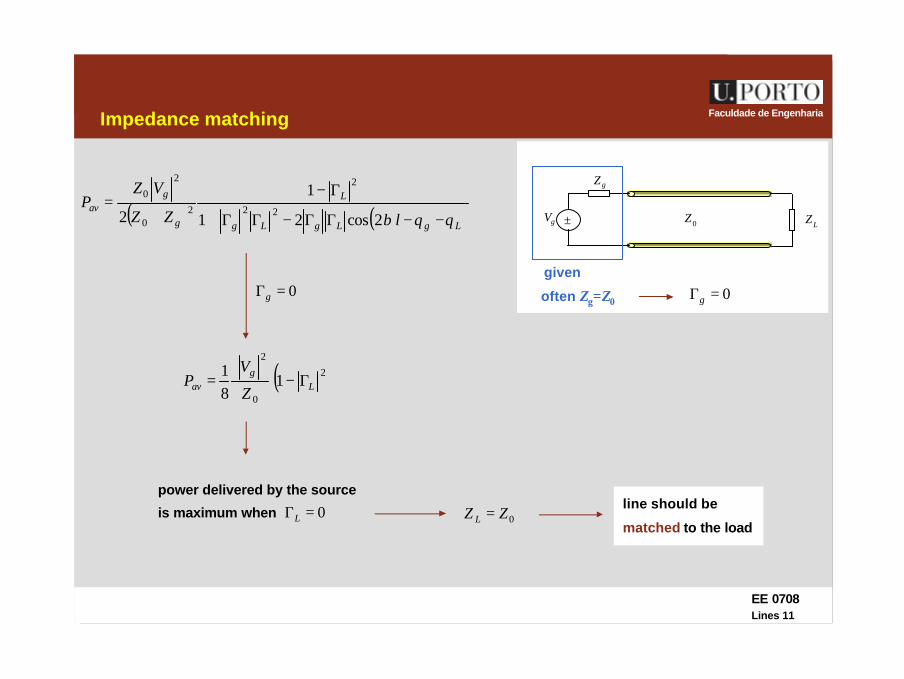
Faculdade de EngenhariaImpedance matching
( ) ( )LgLgLg
L
g
gav
lZZ
VZP
θθβ −−ΓΓ−ΓΓ+
Γ−
+=
2cos21
1
2 22
2
20
2
0
±gV
gZ
LZ0Z
0=Γg
given
often Zg=Z00=Γg
( )2
0
2
181
Lg
av Z
VP Γ−=
power delivered by the source
is maximum when 0=ΓL 0ZZ L =line should be
matched to the load
EE 0708Lines 12
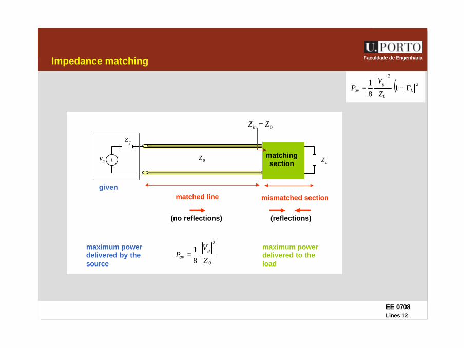
Faculdade de EngenhariaImpedance matching
±gV
gZ
LZ0Z
given
0
2
81
Z
VP
gav =
matching section
0ZZin =
matched line
(no reflections)
maximum power delivered by the source
mismatched section
(reflections)
( )2
0
2
181
Lg
av Z
VP Γ−=
maximum power delivered to the load
EE 0708Lines 13
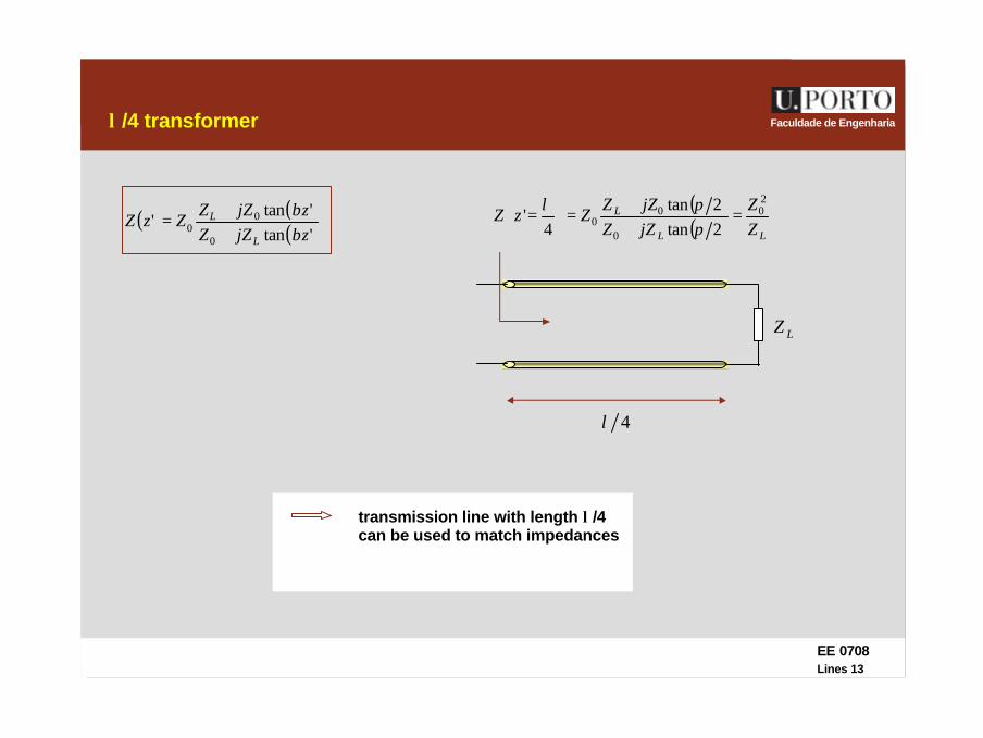
Faculdade de Engenhariaλ /4 transformer
( ) ( )( )'tan
'tan'
0
00 zjZZ
zjZZZzZ
L
L
ββ
++
=( )( ) LL
L
ZZ
jZZjZZ
ZzZ20
0
00 2tan
2tan4
' =++
=
=
ππλ
4λ
LZ
transmission line with length λ/4 can be used to match impedances

EE 0708Lines 14
Faculdade de Engenhariaλ /4 adaptor
( )LZ
ZZ
20/
=
LZ0Z
4λ
/
0ZLZ0Z
mismatched line
00/ ZZZ L=
0Z=
matched line
0ZZ L ≠
Note: ZL must be real if both lines are lossless
EE 0708Lines 15
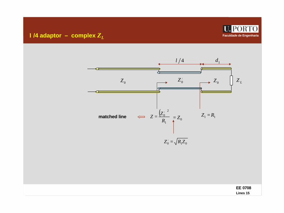
Faculdade de Engenhariaλ /4 adaptor – complex ZL
( )1
20/
RZ
Z =
4λ
/
0Z LZ0Z
010/ ZRZ =
1d
11 RZ =0Z=matched line
0Z
EE 0708Lines 16
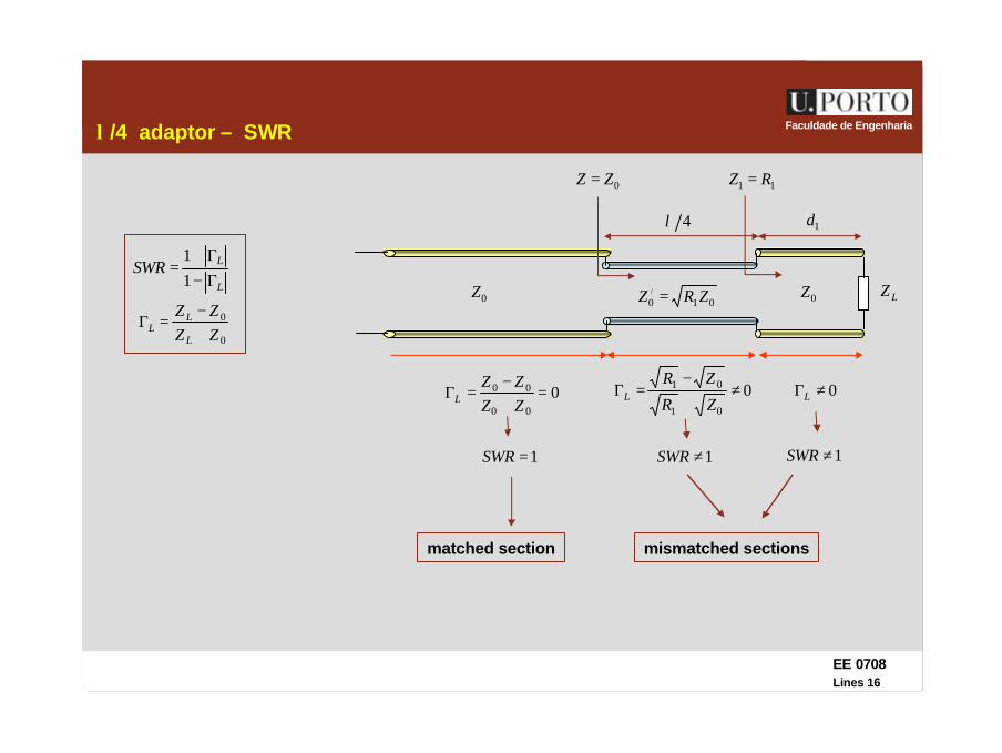
Faculdade de Engenhariaλ /4 adaptor – SWR
0ZZ =
4λ
010/ ZRZ = LZ0Z
1d
11 RZ =
0ZL
LSWRΓ−Γ+
=11
0
0
ZZZZ
L
LL +
−=Γ
0≠ΓL001
01 ≠+
−=Γ
ZR
ZRL
mismatched sections
000
00 =+−
=ΓZZZZ
L
1≠SWR1≠SWR1=SWR
matched section
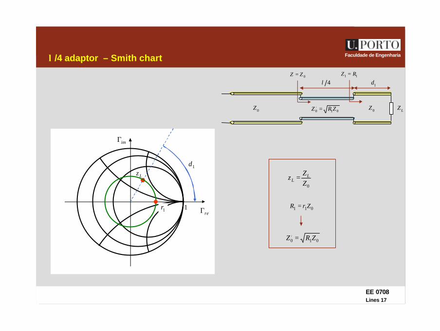
EE 0708Lines 17
Faculdade de Engenhariaλ /4 adaptor – Smith chart
LZ
0ZZ =4λ
010/ ZRZ =0Z
1d11 RZ =
0Z
reΓ
imΓ
1
0ZZ
z LL =Lz
1d
1r 011 ZrR =
010/ ZRZ =

EE 0708Lines 18
Faculdade de Engenharia
reΓ
imΓ
1reΓ
imΓ
1
λ /4 adaptor – different frequency
LZ
02 ZZ =42 pd λ=
0Z
1d11 RZ =
0Z
Lz1d
1r
design: pff =
mismatched line
pp f
v=λ
dd f
v=λ
010/ ZRZ =
4/2 dd λ≠
1zLz
1d
11 rz ≠
010/ ZRZ ≠
02 ZZ ≠
pd fff ≠=different frequency:
EE 0708Lines 19
Faculdade de Engenharia
matched line
aa jB
jX1
=
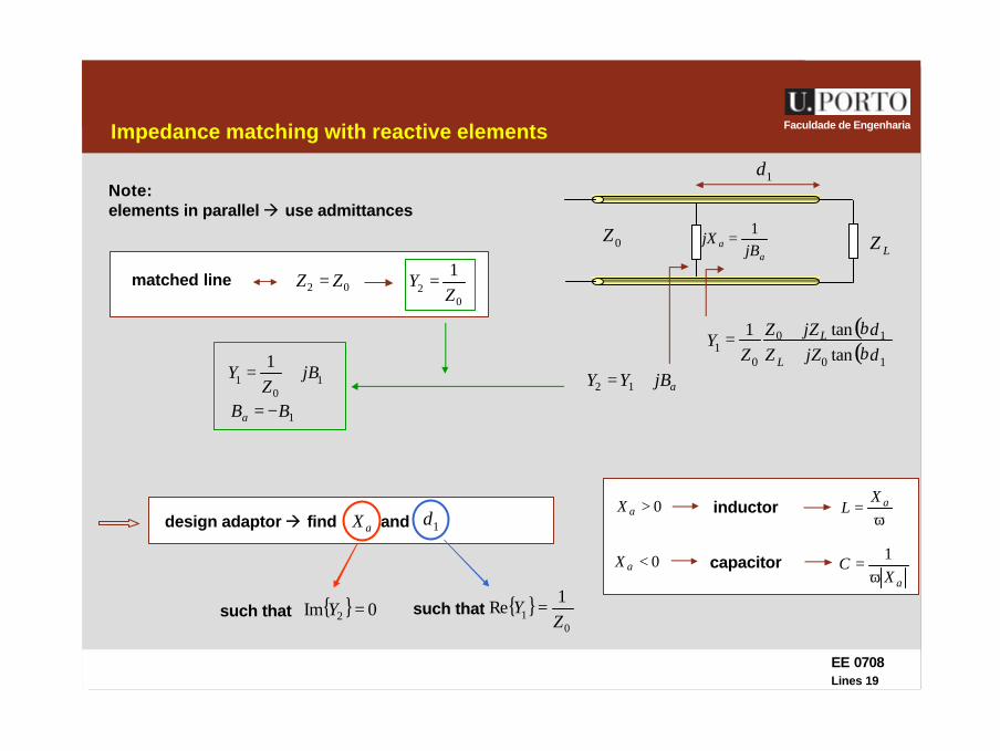
Impedance matching with reactive elements
LZ0Z
Note:elements in parallel à use admittances
ajBYY += 12
1d
10
11
jBZ
Y +=
02 ZZ =0
21Z
Y =
1BBa −=
design adaptor à find and aX 1d
such that { }0
11
ReZ
Y =such that { } 0Im 2 =Y
( )( )10
10
01 tan
tan1djZZdjZZ
ZY
L
L
ββ
++
=
0>aXω
= aXLinductor
0<aXaX
Cω
= 1capacitor

EE 0708Lines 20
Faculdade de Engenharia
aa jB
jX1
=
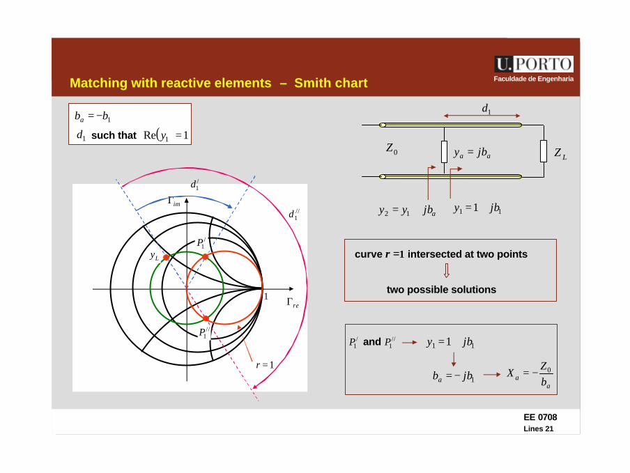
Matching with reactive elements – Smith chart
LZ0Z
ajBYY += 12
1d
10
11
jBZ
Y +=
normalized admittances:
0ZZ
z =0
01YZ
ZZ
zy ===
11 1 jby +=
aa jby =
ajbyy += 12
matching condition: 02 ZZ = 12 =y
12 =y
11 1 jby +=ajbyy += 12
1bba −=
1d such that ( ) 1Re 1 =y
EE 0708Lines 21
Faculdade de EngenhariaMatching with reactive elements – Smith chart
reΓ
imΓ
1
Ly
1bba −=
1d such that ( ) 1Re 1 =y
LZ0Z
11 1 jby +=
aa jby =
ajbyy += 12
1d
1=r
/1P
//1P
/1d
//1d
curve r =1 intersected at two points
two possible solutions
/1P //
1Pand 11 1 jby +=
1jbba −=a
a bZ
X 0−=
EE 0708Lines 22
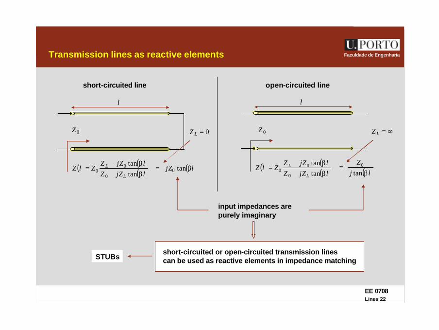
Faculdade de EngenhariaTransmission lines as reactive elements
l
( ) ( )( )ljZZ
ljZZZlZ
L
L
β+β+
=tantan
0
00
0=LZ
( )ljZ β= tan0
short-circuited line
( ) ( )( )ljZZ
ljZZZlZ
L
L
β+β+
=tantan
0
00 ( )lj
Zβ
=tan
0
0Z
input impedances arepurely imaginary
short-circuited or open-circuited transmission linescan be used as reactive elements in impedance matching
l
∞=LZ
open-circuited line
0Z
STUBs
EE 0708Lines 23
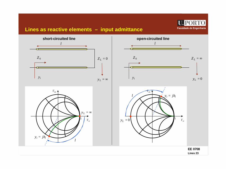
Faculdade de EngenhariaLines as reactive elements – input admittance
l
0=LZ
∞=Ly
short-circuited line
0Z
l
∞=LZ
open-circuited line
0Z
iy
reΓ
imΓ
1
ii jby =
∞=Ly
l
0=Ly
reΓ
imΓ
10=Ly
ii jby =l
iy
EE 0708Lines 24
Faculdade de Engenharia
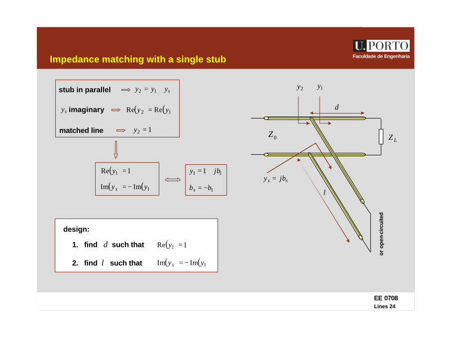
design:
Impedance matching with a single stub
LZ0Z
d
l
2y
ss jby =
( ) ( )12 ReRe yy =imaginarysy
matched line 12 =y
( ) 1Re 1 =y
syyy += 12stub in parallel 1y
( ) ( )1ImIm yy s −=
1. find d such that ( ) 1Re 1 =y
2. find l such that ( ) ( )1ImIm yy s −=
11 1 jby +=
1bbs −=
or
op
en-c
ircu
ited
EE 0708Lines 25
Faculdade de Engenharia
reΓ
imΓ
1
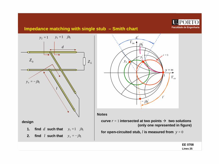
Impedance matching with single stub – Smith chart
Notes
LZ0Z
d
l
12 =y
1jby s −=
11 1 jby += /d
/1jb
∞=y
1=r
Ly
1. find d such that 11 1 jby +=
2. find l such that 1jby s −=
curve r = 1 intersected at two points à two solutions(only one represented in figure)
/l/1jb−
for open-circuited stub, l is measured from y = 0
design
/1y

EE 0708Lines 26
Faculdade de EngenhariaImpedance matching with single stub – Smith chart
reΓ
imΓ
1
/d
/1jb
Ly
/scl
/1jb−
/1y /
ocl
reΓ
imΓ
1
//d
//1jb−
//1y
Ly
//scl //
1jb
//ocl
solution 1 solution 2
EE 0708Lines 27
Faculdade de Engenharia
1
/d
/1jb
Ly
/l/1jb−
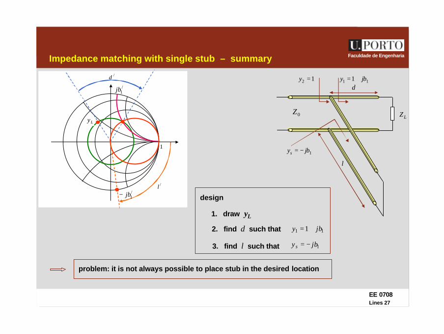
Impedance matching with single stub – summary
LZ0Z
d
l
12 =y
1jbys −=
11 1 jby +=
1. draw yL
11 1 jby +=
3. find l such that 1jby s −=
design
2. find d such that
problem: it is not always possible to place stub in the desired location

EE 0708Lines 28
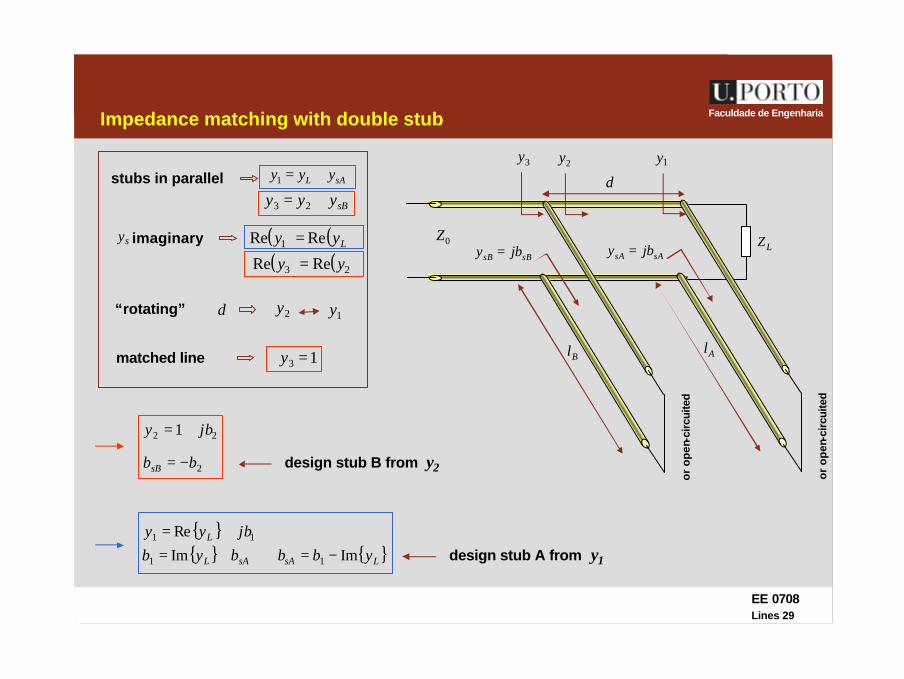
Faculdade de EngenhariaImpedance matching with double stub
LZ0Z
d
Bl
3y
sAsA jby =
2y
or
op
eb-c
ircu
ited
sBsB jby =
Al
1y
or
op
en-c
ircu
ited
when the location of the stub is predefined the transmission line should be matchedusing a double stub
design of adaptor à obtain lA and lB
for a given d
EE 0708Lines 29
Faculdade de EngenhariaImpedance matching with double stub
LZ0Z
d
Bl
3y
sAsA jby =
2y
or
op
en-c
ircu
ited
or
op
en-c
ircu
ited
sBsB jby =
Al
1ysAL yyy +=1stubs in parallel
sByyy += 23
sy ( ) ( )Lyy ReRe 1 =imaginary
( ) ( )23 ReRe yy =
matched line 13 =y
d“rotating” 2y 1y
design stub A from y1
22 1 jby +=
2bbsB −= design stub B from y2
{ } { }LsAsAL ybbbyb ImIm 11 −=⇔+={ } 11 Re jbyy L +=
EE 0708Lines 30
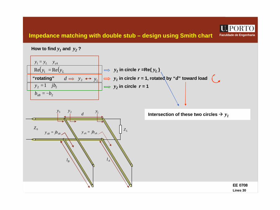
Faculdade de EngenhariaImpedance matching with double stub – design using Smith chart
How to find y1 and y2 ?
sAL yyy +=1
( ) ( )Lyy ReRe 1 =
d“rotating” 2y 1y
2bbsB −=22 1 jby +=
y1 in circle r = 1, rotated by “d” toward load
y1 in circle r =Re{ yL }
y2 in circle r = 1
LZ0Z
d
Bl
3y
sAsA jby =
2y
sBsB jby =
Al
1yIntersection of these two circles à y1
EE 0708Lines 31
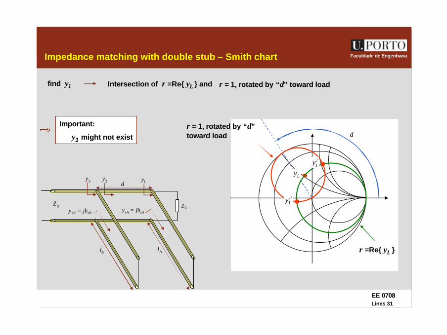
Faculdade de EngenhariaImpedance matching with double stub – Smith chart
r = 1, rotated by “d” toward loadIntersection of r =Re{ yL } and
LZ0Z
d
Bl
3y
sAsA jby =
2y
sBsB jby =
Al
1y
d
Ly
r = 1, rotated by “d”toward load
r =Re{ yL }
/1y
//1y
find y1
Important:
y1 might not exist

EE 0708Lines 32
Faculdade de EngenhariaImpedance matching with double stub – Smith chart
rotate y1 by “d” toward generator
LZ0Z
d
Bl
3y
sAsA jby =
2y
sBsB jby =
Al
1y/1y
//1y
find y2
//2y
/2y
d
EE 0708Lines 33
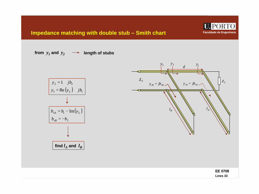
Faculdade de EngenhariaImpedance matching with double stub – Smith chart
length of stubs
LZ0Z
d
Bl
3y
sAsA jby =
2y
sBsB jby =
Al
1y
from y1 and y2
22 1 jby +=
2bbsB −=
{ }LsA ybb Im1 −=
{ } 11 Re jbyy L +=
find lA and lB
EE 0708Lines 34
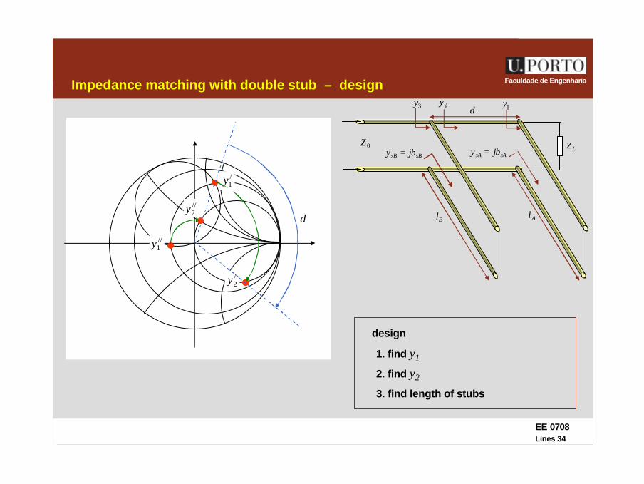
Faculdade de EngenhariaImpedance matching with double stub – design
2. find y2
LZ0Z
d
Bl
3y
sAsA jby =
2y
sBsB jby =
Al
1y
design
3. find length of stubs
/1y
//1y
//2y
/2y
d
1. find y1
EE 0708Lines 35
Faculdade de Engenharia
/1y
//1y
//2y
/2y
d
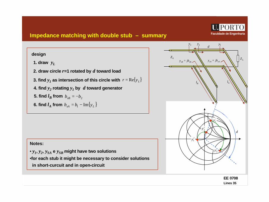
Impedance matching with double stub – summary
2. draw circle r=1 rotated by d toward load
LZ0Z
d
Bl
3y
sAsA jby =
2y
sBsB jby =
Al
1y
design
1. draw yL
3. find y1 as intersection of this circle with { }Lyr Re=
4. find y2 rotating y1 by d toward generator
5. find lB from 2bbsB −=
6. find lA from { }LsA ybb Im1 −=
Notes:
• y1, y2, ySA e ySB might have two solutions
•for each stub it might be necessary to consider solutions
in short-curcuit and in open-circuit
EE 0708Lines 36
Faculdade de Engenharia
Ly
d
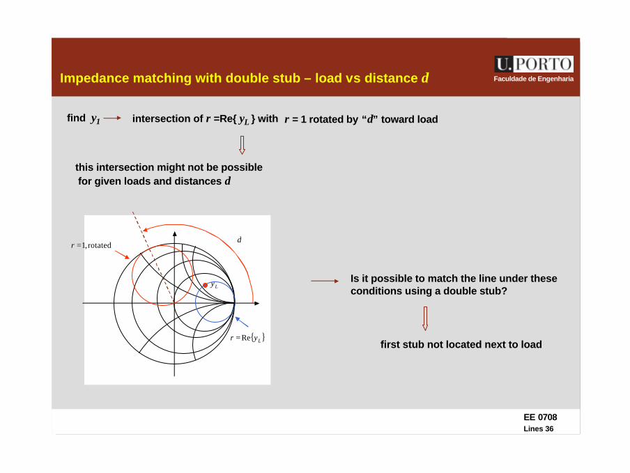
Impedance matching with double stub – load vs distance d
r = 1 rotated by “d” toward loadintersection of r =Re{ yL } with find y1
this intersection might not be possiblefor given loads and distances d
{ }Lyr Re=
rotated,1=r
Is it possible to match the line under theseconditions using a double stub?
first stub not located next to load
EE 0708Lines 37
Faculdade de Engenharia
LZ0Z
d
Bl
3y
sAsA jby =
2y
sBsB jby =
Al
1yLd4y
Ly
drotated,1=r
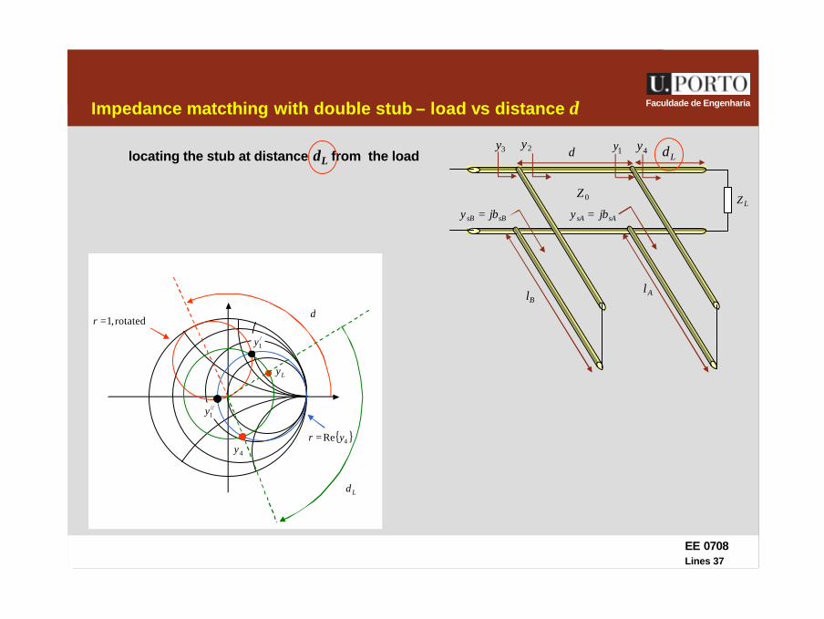
Impedance matcthing with double stub – load vs distance d
locating the stub at distance dL from the load
Ld
{ }4Re yr =4y
/1y
//1y

EE 0708Lines 38
Faculdade de EngenhariaImpedance matching – final conclusions
•impedance matching is only exact at the design frequency
•only the main line is matched
•a given method will not always work:
λ/4 linesà sometimes it is not possible to find lines with desired
single stub à the desired location for the stub might not be accessible
doule stub à it might not exist a solution for y1 and it might not be possible to
/0Z
locate the stub at a distance dL from the load
EE 0708Lines 39
Faculdade de EngenhariaProblem
EE 0708Lines 40
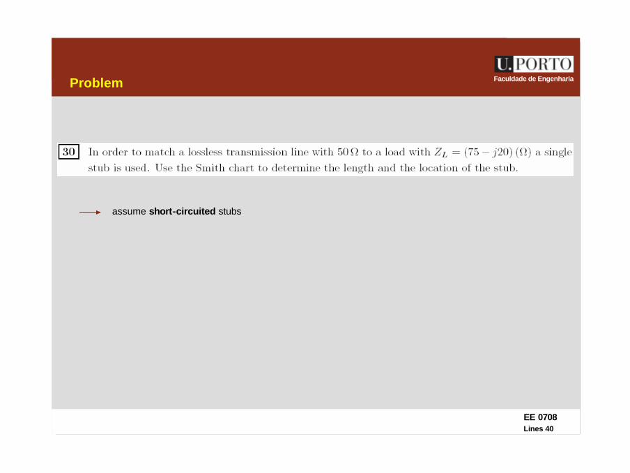
Faculdade de EngenhariaProblem
assume short-circuited stubs
EE 0708Lines 41
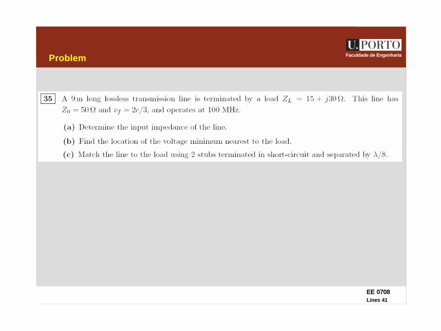
Faculdade de EngenhariaProblem

EE 0708Lines 42
Faculdade de EngenhariaTransients in lossless lines with resistive loads
lossless lines à
LCv 1=
CL
RZ == 00
±gV
gR
0
LR+
−LV
LI
zl−
0=t
0R
−1V
reflected at the load
+1V
incident
+2V
reflected at source
at a given location of the line, the voltage (current) at a given
instant is equal to the sum of all the voltage (current) waves that have reached that location
need to know the amplitude and location of all waves as function of time
EE 0708Lines 43
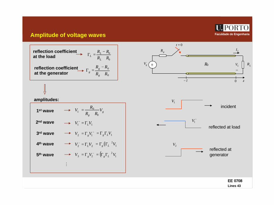
Faculdade de EngenhariaAmplitude of voltage waves
±gV
gR
0
LR+
−LV
LI
zl−
0=t
0R
−1V
reflected at load
+1V
incident
+2V
reflected at generator
reflection coefficient at the load
0
0
RRRR
L
LL +
−=Γ
gg
VRR
RV
0
01 +
=+
2nd wave +− Γ= 11 VV L
3rd wave −+ Γ= 12 VV g+ΓΓ= 1VLg
4th wave +− Γ= 22 VV L ( ) +2ΓΓ= 1VLg
5th wave −+ Γ= 23 VV g ( ) +2ΓΓ= 1VLg
reflection coefficient at the generator 0
0
RR
RR
g
gg +
−=Γ
M
1st wave
amplitudes:
EE 0708Lines 44
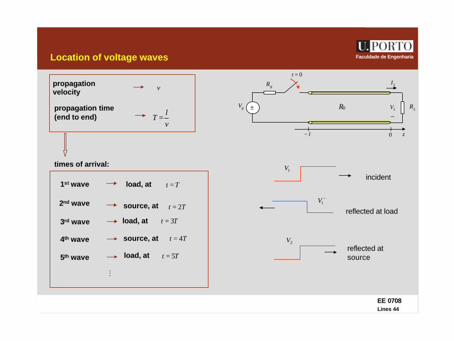
Faculdade de EngenhariaLocation of voltage waves
±gV
gR
0
LR+
−LV
LI
zl−
0=t
0R
−1V
reflected at load
+1V
incident
+2V
reflected at source
propagation time (end to end)
vl
T =
M
propagationvelocity v
load, at Tt =1st wave
times of arrival:
2nd wave source, at Tt 2=
3rd wave load, at Tt 3=
4th wave source, at Tt 4=
5th wave load, at Tt 5=
EE 0708Lines 45
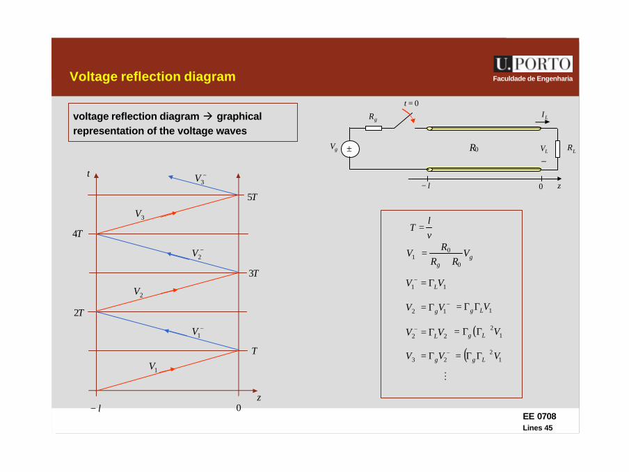
Faculdade de EngenhariaVoltage reflection diagram
±gV
gR
0
LR+
−LV
LI
zl−
0=t
0R
voltage reflection diagram à graphical representation of the voltage waves
z0l−
t
T2
T
T3
T5
T4
gg
VRR
RV
0
01 +
=+
vl
T =
+1V
+− Γ= 11 VV L
−1V
+ΓΓ= 1VLg−+ Γ= 12 VV g
+2V
+− Γ= 22 VV L ( ) +2ΓΓ= 1VLg
−2V
−+ Γ= 23 VV g ( ) +2ΓΓ= 1VLg
+3V
M
−3V
EE 0708Lines 46
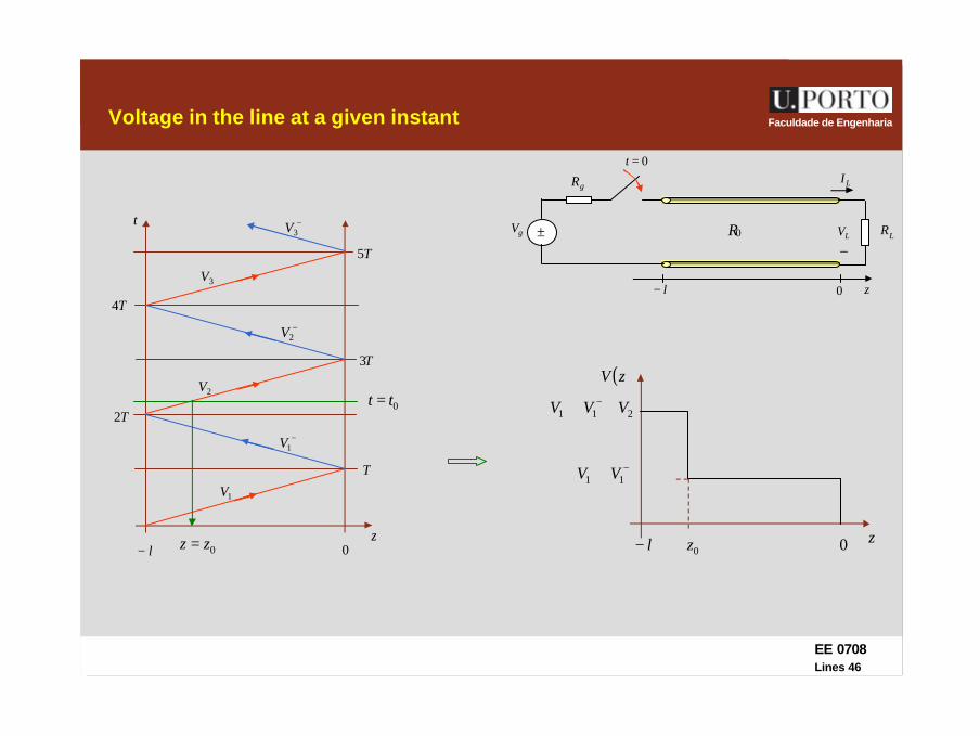
Faculdade de EngenhariaVoltage in the line at a given instant
±gV
gR
0
LR+
−LV
LI
zl−
0=t
0R
z0l−
t
T2
T
T3
T5
T4
+1V
−1V
+2V
−2V
+3V
−3V
0tt =
0zz =
−+ + 11 VV
+−+ ++ 211 VVV
0z z0l−
( )zV
EE 0708Lines 47
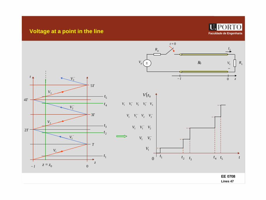
Faculdade de EngenhariaVoltage at a point in the line
±gV
gR
0
LR+
−LV
LI
zl−
0=t
0R
z0l−
t
T2
T
T3
T5
T4
+1V
−1V
+2V
−2V
+3V
−3V
1t
0zz =
4t
2t
5t
3t
−+ + 11 VV
+−+ ++ 211 VVV
1t t0
( )0zV
+1V
2t 3t 5t4t
−+−+ +++ 2211 VVVV
+−+−+ ++++ 32211 VVVVV

EE 0708Lines 48
Faculdade de EngenhariaVoltage at the load
±gV
gR
0
LR+
−LV
LI
zl−
0=t
0R
z0l−
t
T2
T
T3
T5
T4
+1V
−1V
+2V
−2V
+3V
−3V
−+ + 11 VV
T t0
LV
T3 T5
−+−+ +++ 2211 VVVV
−+−+−+ +++++ 332211 VVVVVV
EE 0708Lines 49
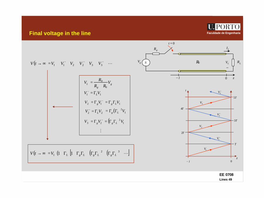
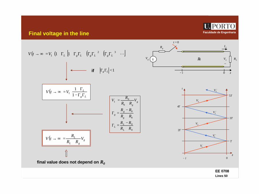
Faculdade de EngenhariaFinal voltage in the line
( ) L++++++=∞→ −+−+−+332211 VVVVVVtV
z0l−
t
T2
T
T3
T5
T4
+1V
−1V
+2V
−2V
+3V
−3V
±gV
gR
0
LR+
−LV
LI
zl−
0=t
0R
gg
VRR
RV
0
01 +
=+
+− Γ= 11 VV L
−+ Γ= 12 VV g+ΓΓ= 1VLg
+− Γ= 22 VV L ( ) +2ΓΓ= 1VLg
−+ Γ= 23 VV g ( ) +2ΓΓ= 1VLg
M
( ) ( ) ( ) ( )[ ]L+ΓΓ+ΓΓ+ΓΓ+Γ+=∞→ + 321 11 LgLgLgLVtV
EE 0708Lines 50
Faculdade de EngenhariaFinal voltage in the line
z0l−
t
T2
T
T3
T5
T4
+1V
−1V
+2V
−2V
+3V
−3V
±gV
gR
0
LR+
−LV
LI
zl−
0=t
0R( ) ( ) ( ) ( )[ ]L+ΓΓ+ΓΓ+ΓΓ+Γ+=∞→ + 32
1 11 LgLgLgLVtV
1<ΓΓ Lgif
( )Lg
LVtVΓΓ−
Γ+=∞→ +
11
1
( ) ggL
L VRR
RtV
+=∞→
0
0
0
0
0
01
RRRR
RR
RR
VRR
RV
L
LL
g
gg
gg
+−
=Γ
+
−=Γ
+=+
final value does not depend on R0
EE 0708Lines 51
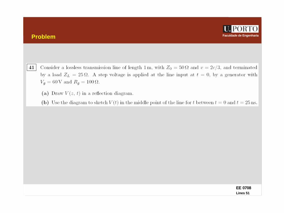
Faculdade de EngenhariaProblem

EE 0708Lines 52
Faculdade de EngenhariaProblem


![t Z v v Á } l vbhiksha/courses/deeplearning/Spring.2018/... · 2018. 1. 22. · d l Z u } ] o Ç EE U l o v ] v P î Z W EE v Z ] v](https://img.pdfslide.us/doc/110x75/60c5177c8d3ae846c1659058/t-z-v-v-l-v-bhikshacoursesdeeplearningspring2018-2018-1-22-d.jpg)