Embed Size (px)
Citation preview
Transmission:Subject:
Application:Issue Date:
Honda 5-SpeedTCC Shudder or MoanHondaJanuary, 2014
Technical Bulletin #1580
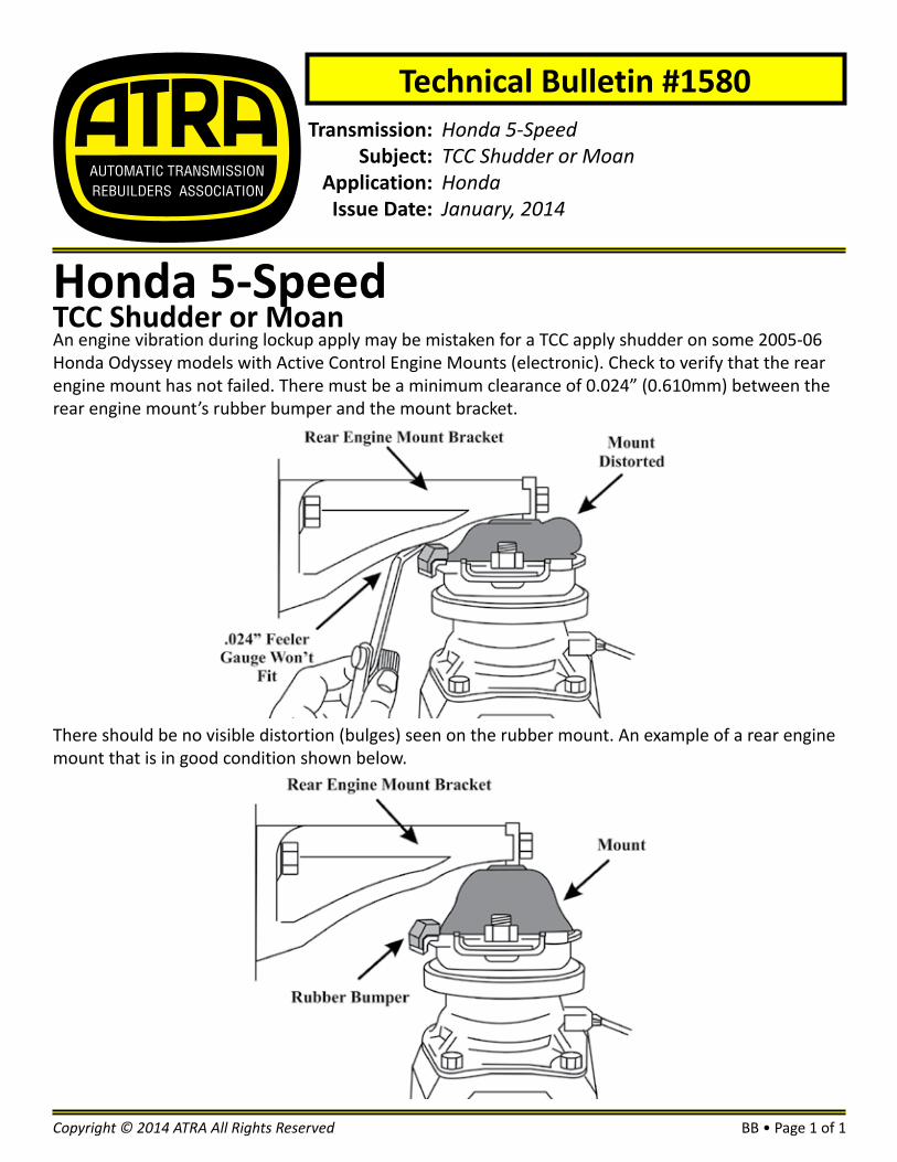
Honda 5-SpeedTCC Shudder or MoanAn engine vibration during lockup apply may be mistaken for a TCC apply shudder on some 2005-06 Honda Odyssey models with Active Control Engine Mounts (electronic). Check to verify that the rear engine mount has not failed. There must be a minimum clearance of 0.024” (0.610mm) between the rear engine mount’s rubber bumper and the mount bracket.
BB • Page 1 of 1Copyright © 2014 ATRA All Rights Reserved
There should be no visible distortion (bulges) seen on the rubber mount. An example of a rear engine mount that is in good condition shown below.

Transmission:Subject:
Application:Issue Date:
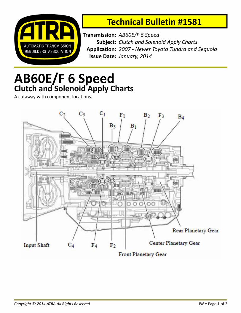
AB60E/F 6 SpeedClutch and Solenoid Apply Charts2007 - Newer Toyota Tundra and SequoiaJanuary, 2014
Technical Bulletin #1581
AB60E/F 6 SpeedClutch and Solenoid Apply ChartsA cutaway with component locations.
JW • Page 1 of 2Copyright © 2014 ATRA All Rights Reserved
JW • Page 2 of 2 Copyright © 2014 ATRA All Rights Reserved
#1581AB60E/F 6 SpeedClutch and Solenoid Apply Charts
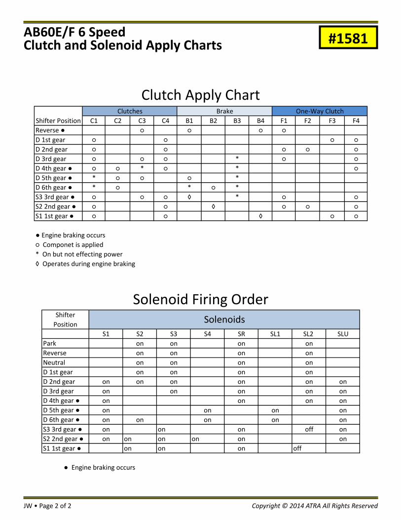
Clutch Apply ChartC1 C2 C3 C4 B1 B2 B3 B4 F1 F2 F3 F4
Reverse ● ○ ○ ○ ○D 1st gear ○ ○ ○ ○D 2nd gear ○ ○ ○ ○ ○D 3rd gear ○ ○ ○ * ○ ○D 4th gear ● ○ ○ * ○ * ○D 5th gear ● * ○ ○ ○ *D 6th gear ● * ○ * ○ *S3 3rd gear ● ○ ○ ○ ◊ * ○ ○S2 2nd gear ● ○ ○ ◊ ○ ○ ○S1 1st gear ● ○ ○ ◊ ○ ○
● Engine braking occurs○ Componet is applied* On but not effecting power◊ Operates during engine braking
Shifter PositionClutches Brake One-Way Clutch
Solenoid Firing OrderShifter
PositionS1 S2 S3 S4 SR SL1 SL2 SLU
Park on on on onReverse on on on onNeutral on on on onD 1st gear on on on onD 2nd gear on on on on on onD 3rd gear on on on on onD 4th gear ● on on on onD 5th gear ● on on on onD 6th gear ● on on on on onS3 3rd gear ● on on on off onS2 2nd gear ● on on on on on onS1 1st gear ● on on on off
Solenoids
● Engine braking occurs
Transmission:Subject:
Application:Issue Date:
4F27E, FN4A-EL, FNR5 & FS5A-ELP0771, P0741/Stator BushingsFord & MazdaJanuary, 2014
Technical Bulletin #1582
4F27E, FN4A-EL, FNR5 & FS5A-ELP0771, P0741/Stator BushingsCodes P0771 Shift Solenoid E Mechanical (Stuck Off) and P0741 TCC Solenoid Circuit (Stuck Off) can be very misleading. Some people go straight to the solenoid and replace it. Then have the same code come back after long drive.
What we need to do is look at freeze frame data and look at the TCC slip rate when code set. Clear codes and drive while watching the tcc slip rate when commanded on. It will take more than one TCC slip per ignition cycle to set codes. Once we see TCC slip rate is changing when commanded then we know for the most part solenoid is ok, and the lock-up valve moved.
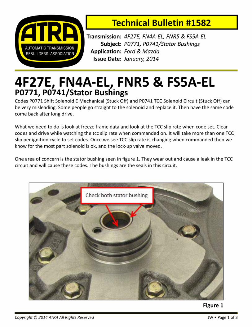
One area of concern is the stator bushing seen in figure 1. They wear out and cause a leak in the TCC circuit and will cause these codes. The bushings are the seals in this circuit.
JW • Page 1 of 3Copyright © 2014 ATRA All Rights Reserved
Figure 1
JW • Page 2 of 3 Copyright © 2014 ATRA All Rights Reserved
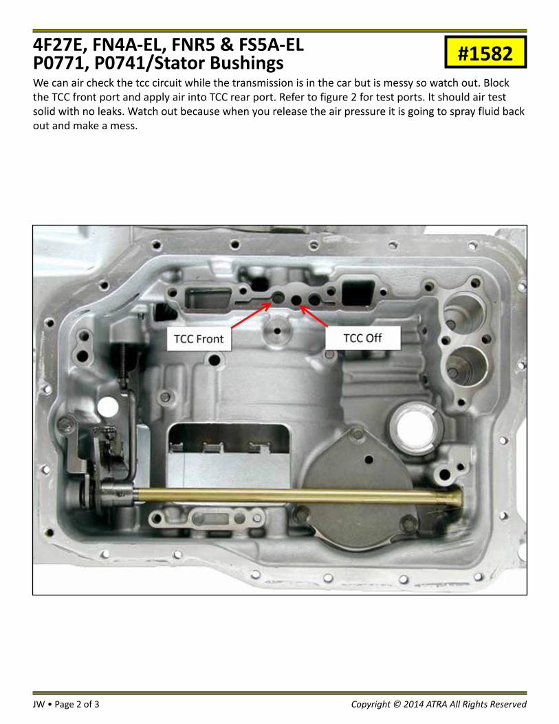
#1582We can air check the tcc circuit while the transmission is in the car but is messy so watch out. Block the TCC front port and apply air into TCC rear port. Refer to figure 2 for test ports. It should air test solid with no leaks. Watch out because when you release the air pressure it is going to spray fluid back out and make a mess.
4F27E, FN4A-EL, FNR5 & FS5A-ELP0771, P0741/Stator Bushings
JW • Page 3 of 3Copyright © 2014 ATRA All Rights Reserved
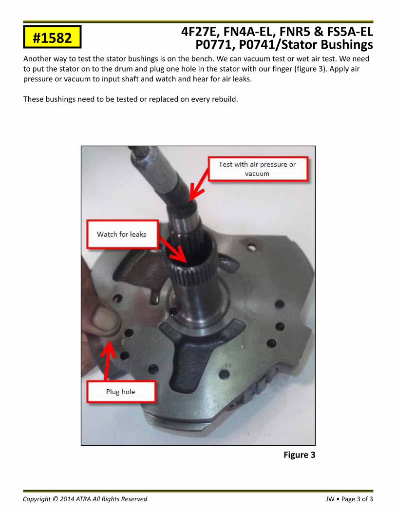
#1582Another way to test the stator bushings is on the bench. We can vacuum test or wet air test. We need to put the stator on to the drum and plug one hole in the stator with our finger (figure 3). Apply air pressure or vacuum to input shaft and watch and hear for air leaks.
These bushings need to be tested or replaced on every rebuild.
Figure 3
4F27E, FN4A-EL, FNR5 & FS5A-ELP0771, P0741/Stator Bushings

Transmission:Subject:
Application:Issue Date:
Honda 4 SpeedTCC Shudder 2002 Honda OdysseyJanuary, 2014
Technical Bulletin #1583
Honda 4 SpeedTCC Shudder
BB • Page 1 of 1Copyright © 2014 ATRA All Rights Reserved
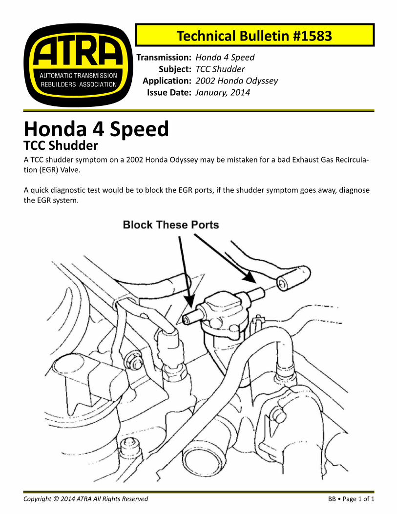
A TCC shudder symptom on a 2002 Honda Odyssey may be mistaken for a bad Exhaust Gas Recircula-tion (EGR) Valve.
A quick diagnostic test would be to block the EGR ports, if the shudder symptom goes away, diagnose the EGR system.

Transmission:Subject:
Application:Issue Date:
Subaru Lineartronic CVTFluid Level ChecksSubaru CVTJanuary, 2014
Technical Bulletin #1584
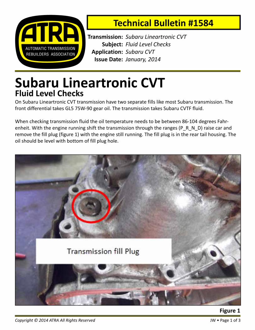
Subaru Lineartronic CVTFluid Level ChecksOn Subaru Lineartronic CVT transmission have two separate fills like most Subaru transmission. The front differential takes GL5 75W-90 gear oil. The transmission takes Subaru CVTF fluid.
When checking transmission fluid the oil temperature needs to be between 86-104 degrees Fahr-enheit. With the engine running shift the transmission through the ranges (P_R_N_D) raise car and remove the fill plug (figure 1) with the engine still running. The fill plug is in the rear tail housing. The oil should be level with bottom of fill plug hole.
JW • Page 1 of 3Copyright © 2014 ATRA All Rights Reserved
Figure 1
JW • Page 2 of 3 Copyright © 2014 ATRA All Rights Reserved
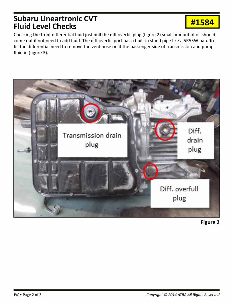
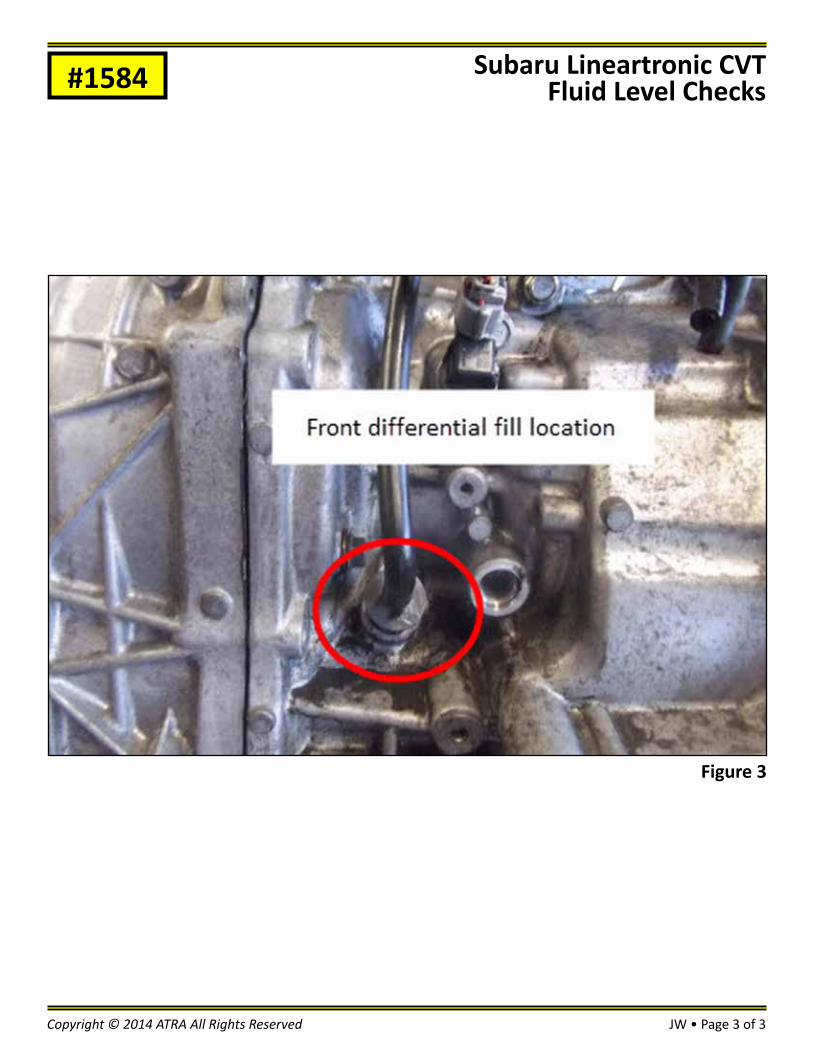
#1584Checking the front differential fluid just pull the diff overfill plug (figure 2) small amount of oil should come out if not need to add fluid. The diff overfill port has a built in stand pipe like a 5R55W pan. To fill the differential need to remove the vent hose on it the passenger side of transmission and pump fluid in (figure 3).
Subaru Lineartronic CVTFluid Level Checks
Figure 2
JW • Page 3 of 3Copyright © 2014 ATRA All Rights Reserved
#1584 Subaru Lineartronic CVTFluid Level Checks
Figure 3

Transmission:Subject:
Application:Issue Date:
45RFEErratic TCC Operation, TCC Cycling “ON” and “OFF”ChryslerJanuary, 2014
Technical Bulletin #1585
45RFEErratic TCC Operation, TCC Cycling “ON” and “OFF”The complaint is TCC Cycling on and off while driving or erratic TCC operation. A commanded torque converter clutch cycling on and off (TCC Shuttle) at 40-50 mph is a common problem on Dodge full size Ram pickups, Dakotas and Durangos.
There are several causes for this, some of which depend on the vehicle year, control system, and engine configuration. We’re going to break the troubleshooting down into easy steps to solve this commanded TCC shuttling problem. TCC shuttling on these vehicles in mainly because the Powertrain Control Module (PCM) is very sensitive to the TPS signal. Fluctuations in the TPS signal greater than 0.20V can cause the PCM to command the TCC to release, then reapply. The problem is usually in the TPS or circuits themselves, the TPS signal being affected by outside interference, or noise from other electrical systems.
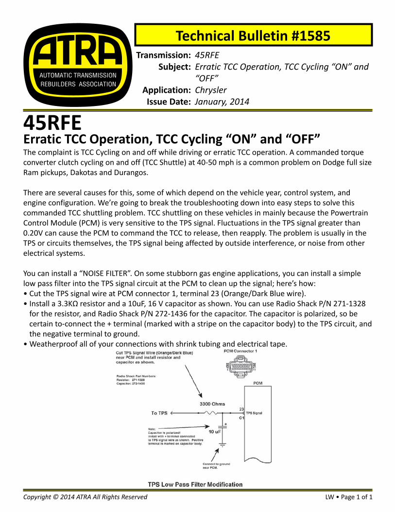
You can install a “NOISE FILTER”. On some stubborn gas engine applications, you can install a simple low pass filter into the TPS signal circuit at the PCM to clean up the signal; here’s how:• Cut the TPS signal wire at PCM connector 1, terminal 23 (Orange/Dark Blue wire).• Install a 3.3KΩ resistor and a 10uF, 16 V capacitor as shown. You can use Radio Shack P/N 271-1328
for the resistor, and Radio Shack P/N 272-1436 for the capacitor. The capacitor is polarized, so be certain to-connect the + terminal (marked with a stripe on the capacitor body) to the TPS circuit, and the negative terminal to ground.
• Weatherproof all of your connections with shrink tubing and electrical tape.
LW • Page 1 of 1Copyright © 2014 ATRA All Rights Reserved

Transmission:Subject:
Application:Issue Date:
A4CF2Adaptive LearningKiaJanuary, 2014
Technical Bulletin #1586
A4CF2Adaptive LearningThe PCM and TCM contain logic to adjust the solenoid duty and line pressure to compensate for nor-mal clutch wear over the life of the transmission. Adaptive value reset and relearn must be performed to provide optimum shift quality after completing the following repairs.
• Replace automatic transmission• Replace PCM or TCM• Reprogram PCM or TCM
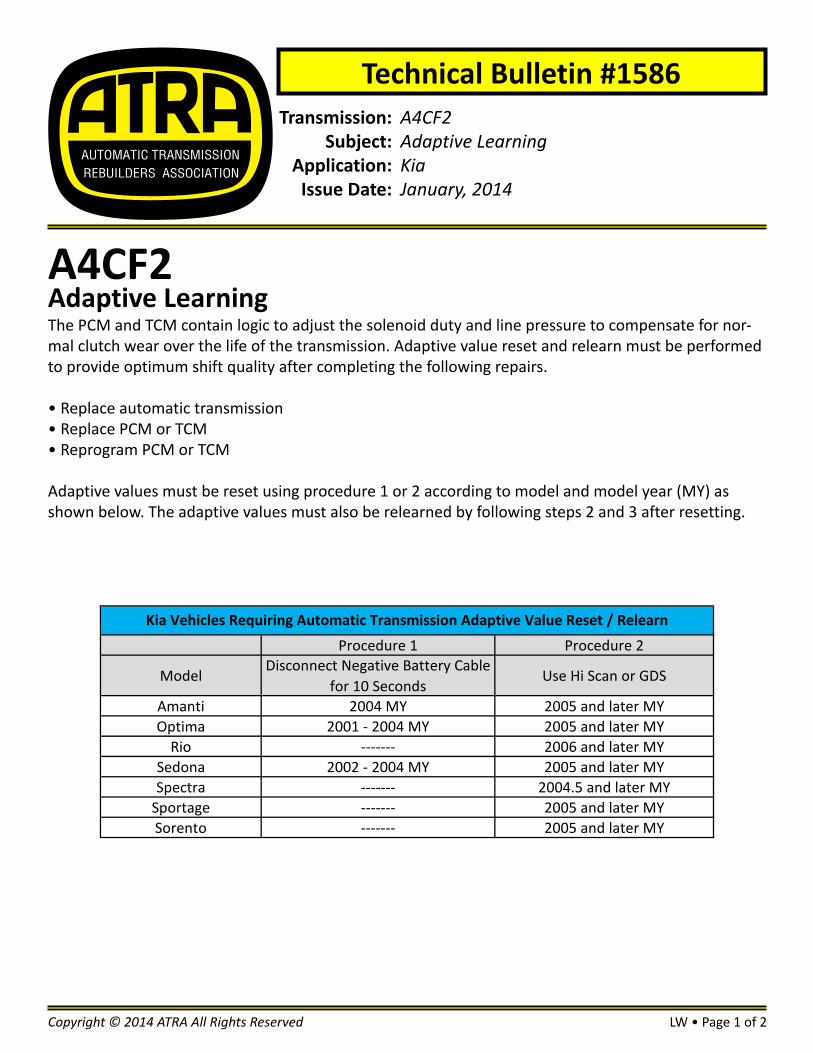
Adaptive values must be reset using procedure 1 or 2 according to model and model year (MY) as shown below. The adaptive values must also be relearned by following steps 2 and 3 after resetting.
LW • Page 1 of 2Copyright © 2014 ATRA All Rights Reserved
Procedure 1 Procedure 2
ModelDisconnect Negative Battery Cable
for 10 SecondsUse Hi Scan or GDS
Amanti 2004 MY 2005 and later MYOptima 2001 - 2004 MY 2005 and later MY
Rio ------- 2006 and later MYSedona 2002 - 2004 MY 2005 and later MYSpectra ------- 2004.5 and later MY
Sportage ------- 2005 and later MYSorento ------- 2005 and later MY
Kia Vehicles Requiring Automatic Transmission Adaptive Value Reset / Relearn
LW • Page 2 of 2 Copyright © 2014 ATRA All Rights Reserved
#1586Use the Scan tool to reset the automatic transmission adaptive values found in the automatic trans-mission section menu. Follow the steps shown in RESETTING AUTO T/A VALUES or INIT OF TCU LEARN-ING menu sections.
1. Hook the scan tool to vehicle and input VIN or auto select VIN2. Select Automatic Transmission system3. Select Vehicle S/W Management tab as shown4. Select “Init Of TCU Learning” as shown5. Ignition key on6. Engine off7. Shift lever in P or N8. Vehicle speed 0 MPH9. Click the “OK” button.10. Adaptive Reset is complete as shown11. Turn the ignition key off for ten seconds
NOTE: The 2005 and later MY Sorento requires the accelerator pedal pushed down 50%. Carefully follow the instructions on the screen.
Driving RelearnDynamic Automatic Transmission Adaptive Learning Procedure:1. Attach your scan tool and monitor ATF temperature and TPS percent.2. Bring ATF temperature to just over 120°F and drive from a stop shifting from 1st to 3rd gears (Five
speeds. - 1st to 4th gears) at 30% TPS (Approx. 3000 RPM shift). Repeat 3 - 5 times until any shock or
flare is eliminated.
NOTE: 2005 and later Sorento Sub-ROM same as above except 8-12% TPS. If TPS goes over 12%, re-learn will not occur, start sequence over.
Static Shift Relearn1. Stop the vehicle and shift into N for three seconds. Shift from N to D for two seconds. Repeat 3 - 5
times until there is no N to D shock.2. Stop the vehicle and shift into N for three seconds. Shift from N to R for two seconds. Repeat 3 - 5
times until there is no N to R shock.
A4CF2Adaptive Learning