Embed Size (px)
Citation preview
Power System Protection Part – VI Dr.Prof.Mohammed Tawfeeq Al-Zuhairi
321
Power system protection Notes
Transmission and distribution lines protection
Dr.Professor Mohammed Tawfeeq Al-Zuhairi
Power System Protection Part – VI Dr.Prof.Mohammed Tawfeeq Al-Zuhairi
321
Transmission and distribution lines protection
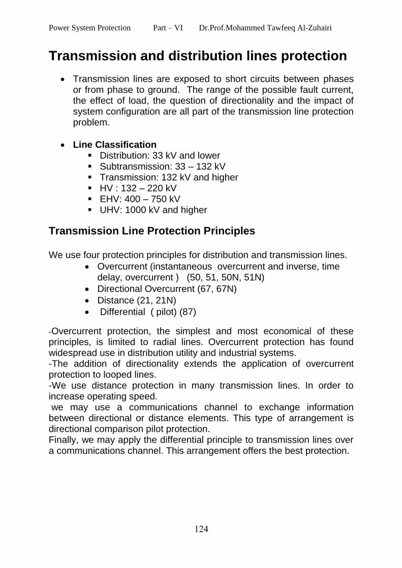
Transmission lines are exposed to short circuits between phases or from phase to ground. The range of the possible fault current, the effect of load, the question of directionality and the impact of system configuration are all part of the transmission line protection problem.
Line Classification Distribution: 33 kV and lower Subtransmission: 33 – 132 kV Transmission: 132 kV and higher HV : 132 – 220 kV EHV: 400 – 750 kV UHV: 1000 kV and higher
Transmission Line Protection Principles We use four protection principles for distribution and transmission lines.
Overcurrent (instantaneous overcurrent and inverse, time delay, overcurrent ) (50, 51, 50N, 51N)
Directional Overcurrent (67, 67N)
Distance (21, 21N)
Differential ( pilot) (87)
-Overcurrent protection, the simplest and most economical of these principles, is limited to radial lines. Overcurrent protection has found widespread use in distribution utility and industrial systems. -The addition of directionality extends the application of overcurrent protection to looped lines. -We use distance protection in many transmission lines. In order to increase operating speed. we may use a communications channel to exchange information between directional or distance elements. This type of arrangement is directional comparison pilot protection. Finally, we may apply the differential principle to transmission lines over a communications channel. This arrangement offers the best protection.
Power System Protection Part – VI Dr.Prof.Mohammed Tawfeeq Al-Zuhairi
321
1.Overcurrent protection of transmission and
distribution lines
Overcurrent protection is the simplest and most economical of TL protection schemes .It is limited to radial lines.
Protection of Radial System by Overcurrent Relay:
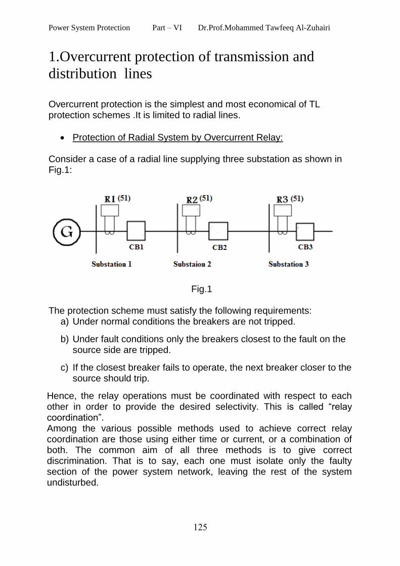
Consider a case of a radial line supplying three substation as shown in Fig.1:
Fig.1
The protection scheme must satisfy the following requirements:
a) Under normal conditions the breakers are not tripped.
b) Under fault conditions only the breakers closest to the fault on the source side are tripped.
c) If the closest breaker fails to operate, the next breaker closer to the source should trip.
Hence, the relay operations must be coordinated with respect to each other in order to provide the desired selectivity. This is called “relay coordination”. Among the various possible methods used to achieve correct relay coordination are those using either time or current, or a combination of both. The common aim of all three methods is to give correct discrimination. That is to say, each one must isolate only the faulty section of the power system network, leaving the rest of the system undisturbed.
Power System Protection Part – VI Dr.Prof.Mohammed Tawfeeq Al-Zuhairi
321
There are three methods for obtaining relay coordination
Discrimination by time (Time-grading).
Discrimination by current (Current-grading).
Discrimination by both time and current (Time-Current grading)
Time-grading (Discrimination by time)
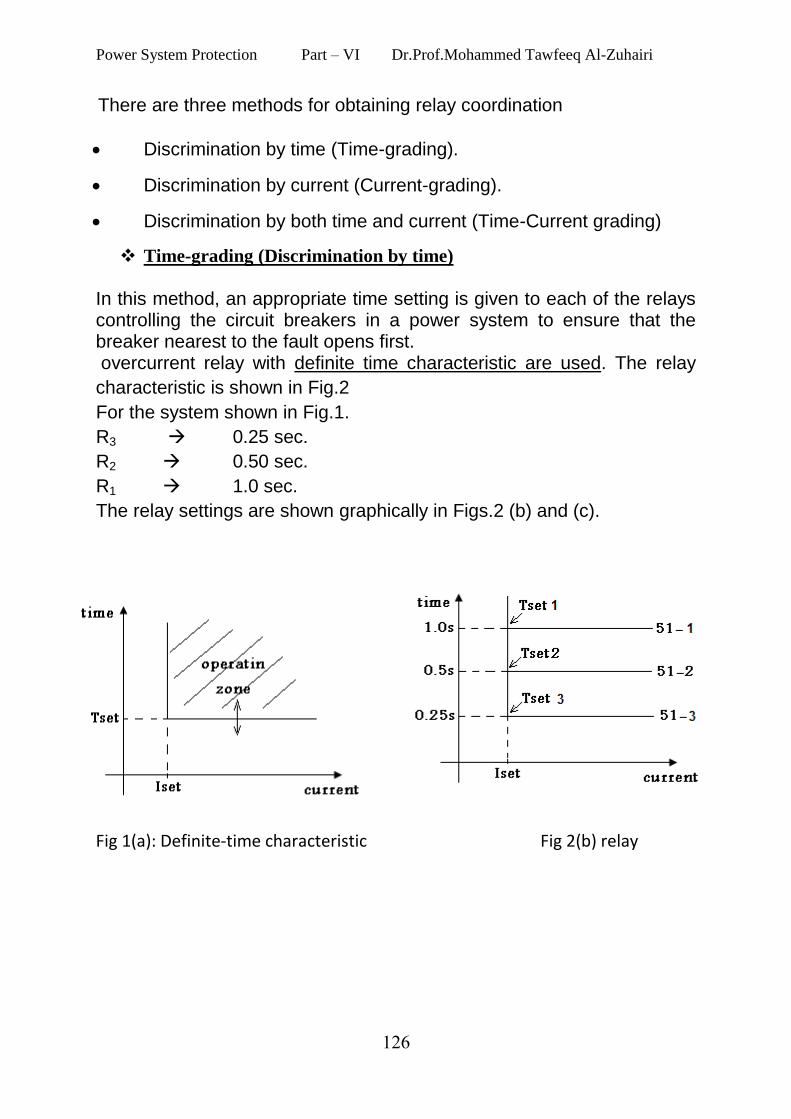
In this method, an appropriate time setting is given to each of the relays controlling the circuit breakers in a power system to ensure that the breaker nearest to the fault opens first. overcurrent relay with definite time characteristic are used. The relay
characteristic is shown in Fig.2
For the system shown in Fig.1.
R3 0.25 sec.
R2 0.50 sec.
R1 1.0 sec.
The relay settings are shown graphically in Figs.2 (b) and (c).
Fig 1(a): Definite-time characteristic Fig 2(b) relay
Power System Protection Part – VI Dr.Prof.Mohammed Tawfeeq Al-Zuhairi
321
settings.
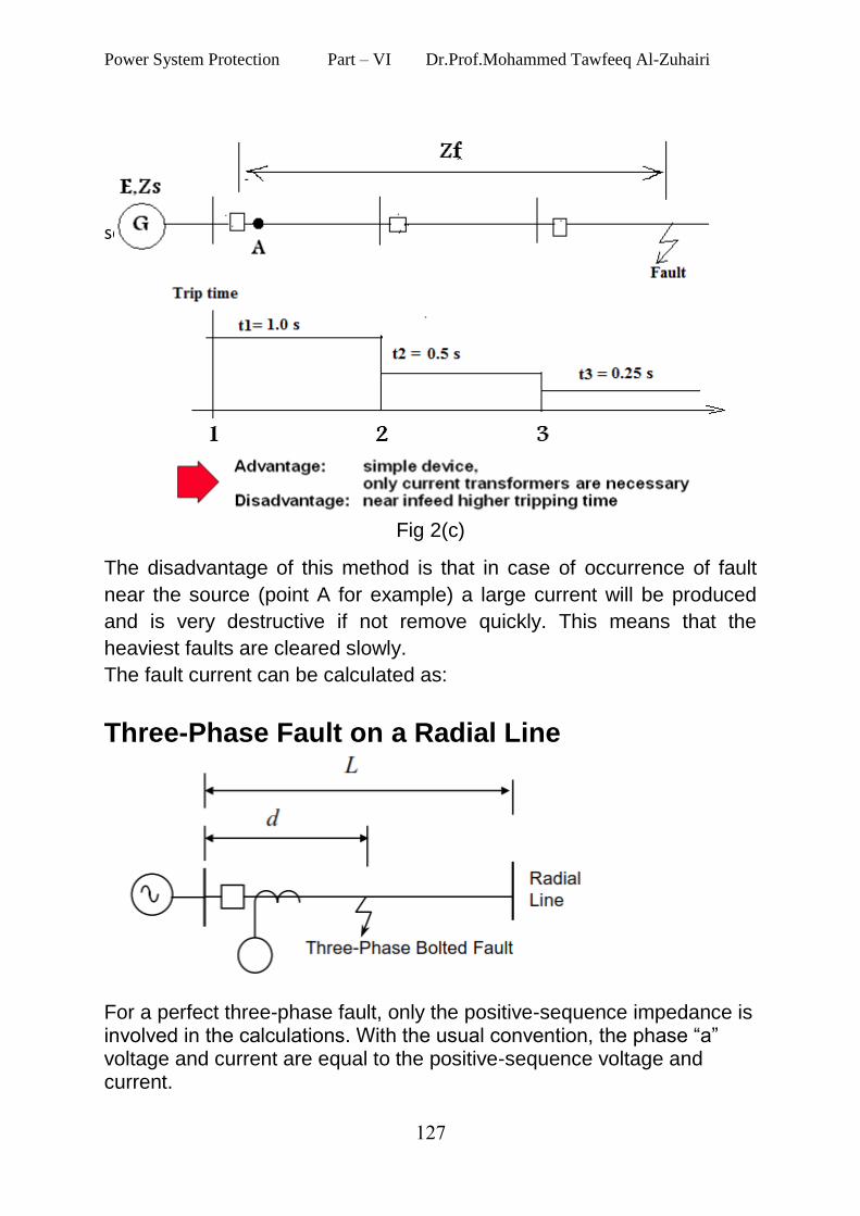
Fig 2(c)
The disadvantage of this method is that in case of occurrence of fault
near the source (point A for example) a large current will be produced
and is very destructive if not remove quickly. This means that the
heaviest faults are cleared slowly.
The fault current can be calculated as:
Three-Phase Fault on a Radial Line
For a perfect three-phase fault, only the positive-sequence impedance is involved in the calculations. With the usual convention, the phase “a” voltage and current are equal to the positive-sequence voltage and current.
Power System Protection Part – VI Dr.Prof.Mohammed Tawfeeq Al-Zuhairi
321
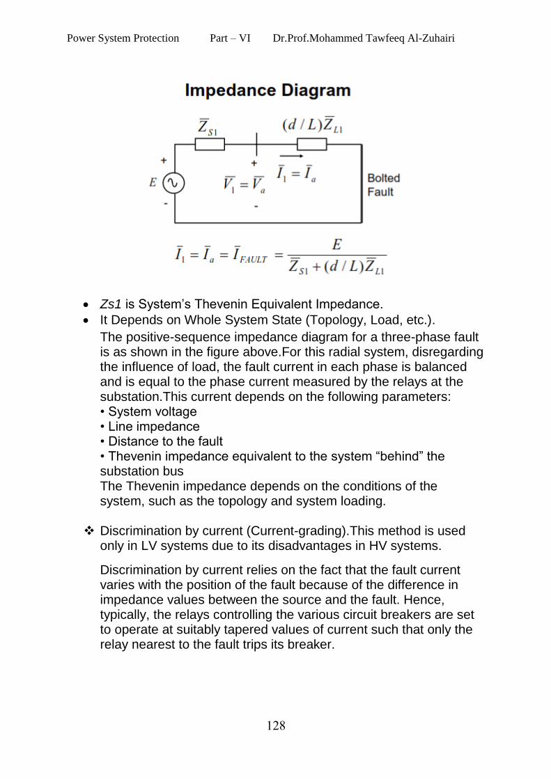
Zs1 is System’s Thevenin Equivalent Impedance.
It Depends on Whole System State (Topology, Load, etc.).
The positive-sequence impedance diagram for a three-phase fault is as shown in the figure above.For this radial system, disregarding the influence of load, the fault current in each phase is balanced and is equal to the phase current measured by the relays at the substation.This current depends on the following parameters: • System voltage • Line impedance • Distance to the fault • Thevenin impedance equivalent to the system “behind” the substation bus The Thevenin impedance depends on the conditions of the system, such as the topology and system loading.
Discrimination by current (Current-grading).This method is used
only in LV systems due to its disadvantages in HV systems.
Discrimination by current relies on the fact that the fault current varies with the position of the fault because of the difference in impedance values between the source and the fault. Hence, typically, the relays controlling the various circuit breakers are set to operate at suitably tapered values of current such that only the relay nearest to the fault trips its breaker.
Power System Protection Part – VI Dr.Prof.Mohammed Tawfeeq Al-Zuhairi
321
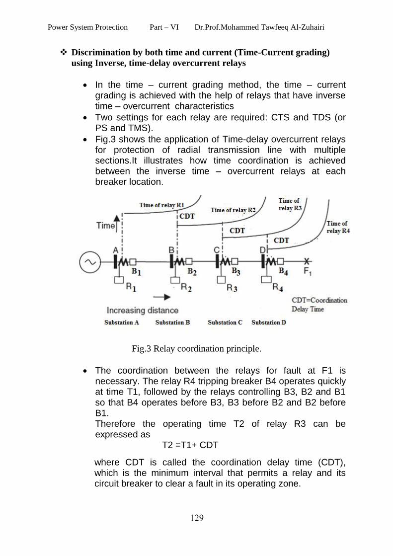
Discrimination by both time and current (Time-Current grading)
using Inverse, time-delay overcurrent relays
In the time – current grading method, the time – current grading is achieved with the help of relays that have inverse time – overcurrent characteristics
Two settings for each relay are required: CTS and TDS (or PS and TMS).
Fig.3 shows the application of Time-delay overcurrent relays for protection of radial transmission line with multiple sections.It illustrates how time coordination is achieved between the inverse time – overcurrent relays at each breaker location.
Fig.3 Relay coordination principle.
The coordination between the relays for fault at F1 is necessary. The relay R4 tripping breaker B4 operates quickly at time T1, followed by the relays controlling B3, B2 and B1 so that B4 operates before B3, B3 before B2 and B2 before B1. Therefore the operating time T2 of relay R3 can be expressed as T2 =T1+ CDT
where CDT is called the coordination delay time (CDT), which is the minimum interval that permits a relay and its circuit breaker to clear a fault in its operating zone.
Power System Protection Part – VI Dr.Prof.Mohammed Tawfeeq Al-Zuhairi
311
1. American school of coordination: In American standard, the time interval between two adjacent relays is called the coordination delay time (CDT). The value of CDT is 0.4 seconds. This comes from:
Fault current interruption time of the circuit breaker (= 0.1 s, or 6 cycles in 60 Hz system).
Error margin of 0.3 s . Hence, CDT=(operating time of breaker B4) + (error margin) Similarly, the operating times of R2 and R1 are: T3=T2 + CDT T4=T3+ CDT CTS and TDS Settings
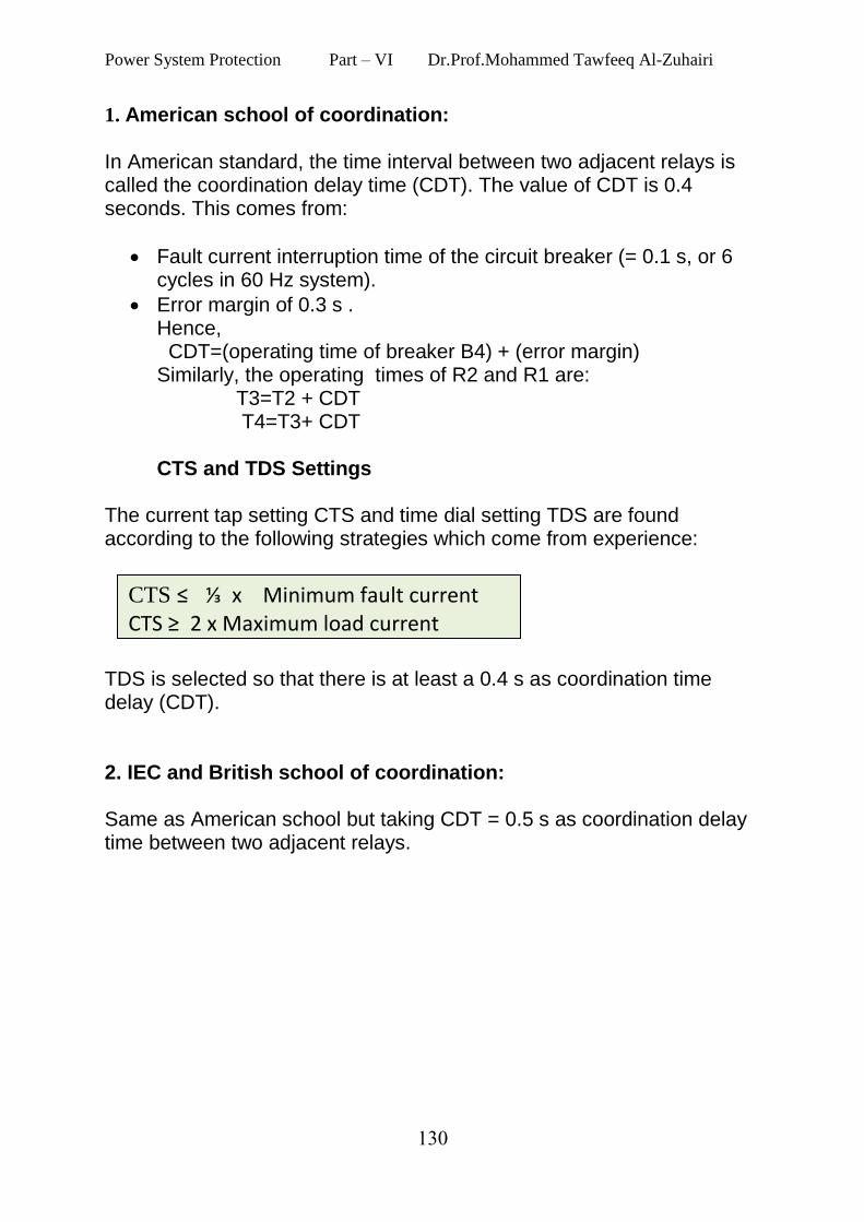
The current tap setting CTS and time dial setting TDS are found according to the following strategies which come from experience:
TDS is selected so that there is at least a 0.4 s as coordination time delay (CDT). 2. IEC and British school of coordination: Same as American school but taking CDT = 0.5 s as coordination delay time between two adjacent relays.
CTS ≤ ⅓ x Minimum fault current CTS ≥ 2 x Maximum load current
Power System Protection Part – VI Dr.Prof.Mohammed Tawfeeq Al-Zuhairi
313
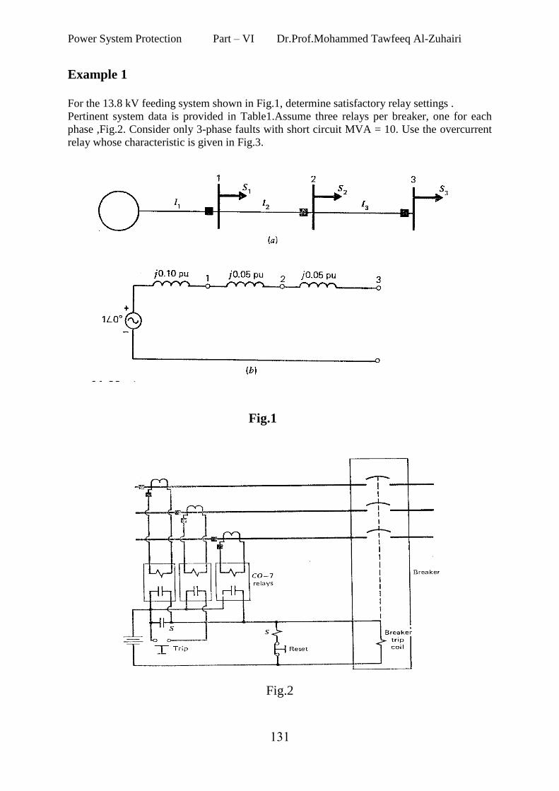
Example 1
For the 13.8 kV feeding system shown in Fig.1, determine satisfactory relay settings .
Pertinent system data is provided in Table1.Assume three relays per breaker, one for each
phase ,Fig.2. Consider only 3-phase faults with short circuit MVA = 10. Use the overcurrent
relay whose characteristic is given in Fig.3.
Fig.1
Fig.2
Power System Protection Part – VI Dr.Prof.Mohammed Tawfeeq Al-Zuhairi
312
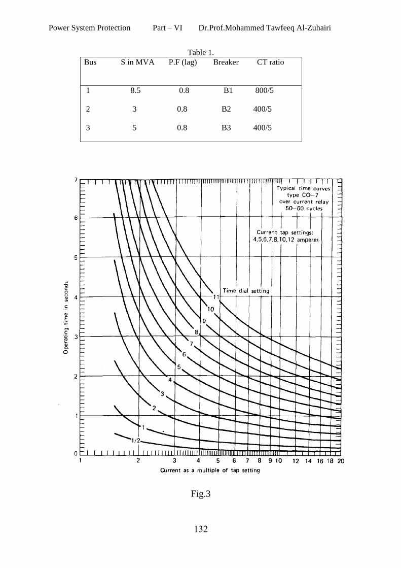
Table 1.
Bus S in MVA P.F (lag) Breaker CT ratio
1 8.5 0.8 B1 800/5
2 3 0.8 B2 400/5
3 5 0.8 B3 400/5
Fig.3
Power System Protection Part – VI Dr.Prof.Mohammed Tawfeeq Al-Zuhairi
311
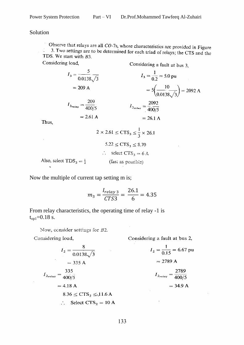
Solution
Now the multiple of current tap setting m is;
From relay characteristics, the operating time of relay -1 is
top1=0.18 s.
Power System Protection Part – VI Dr.Prof.Mohammed Tawfeeq Al-Zuhairi
311
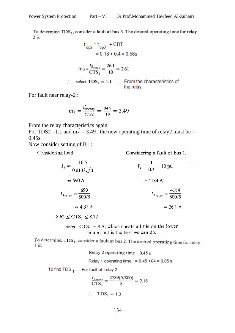
For fault near relay-2 :
From the relay characteristics again
For TDS2 =1.1 and m2’ = 3.49 , the new operating time of relay2 must be =
0.45s.
Now consider setting of B1 :
Power System Protection Part – VI Dr.Prof.Mohammed Tawfeeq Al-Zuhairi
311
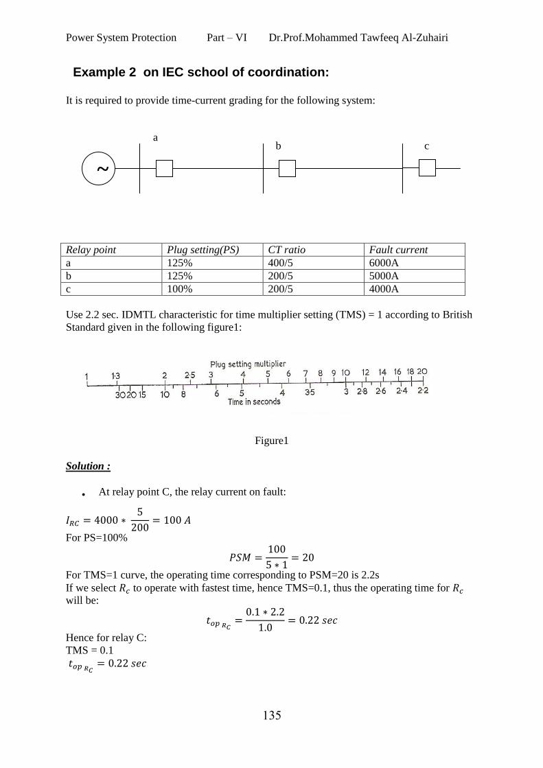
Example 2 on IEC school of coordination: It is required to provide time-current grading for the following system:
Relay point Plug setting(PS) CT ratio Fault current
a 125% 400/5 6000A
b 125% 200/5 5000A
c 100% 200/5 4000A
Use 2.2 sec. IDMTL characteristic for time multiplier setting (TMS) = 1 according to British
Standard given in the following figure1:
Figure1
Solution :
At relay point C, the relay current on fault:
For PS=100%
For TMS=1 curve, the operating time corresponding to PSM=20 is 2.2s
If we select to operate with fastest time, hence TMS=0.1, thus the operating time for
will be:
Hence for relay C:
TMS = 0.1
a b c
~
Power System Protection Part – VI Dr.Prof.Mohammed Tawfeeq Al-Zuhairi
311
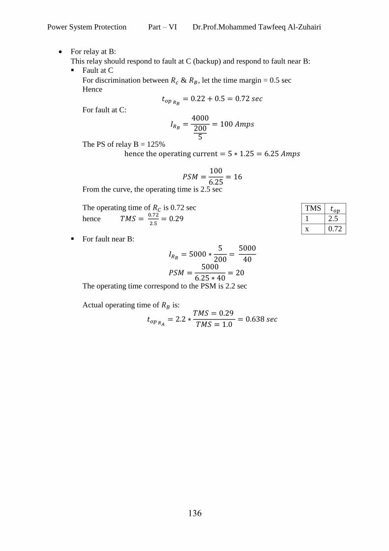
For relay at B:
This relay should respond to fault at C (backup) and respond to fault near B:
Fault at C
For discrimination between & , let the time margin = 0.5 sec
Hence
For fault at C:
The PS of relay B = 125%
From the curve, the operating time is 2.5 sec
The operating time of is 0.72 sec
hence
For fault near B:
The operating time correspond to the PSM is 2.2 sec
Actual operating time of is:
TMS
1 2.5
x 0.72
Power System Protection Part – VI Dr.Prof.Mohammed Tawfeeq Al-Zuhairi
311
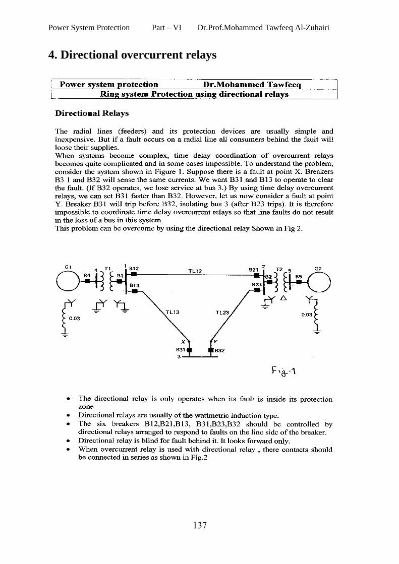
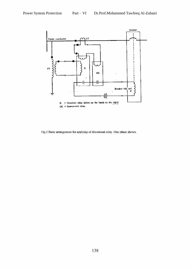
4. Directional overcurrent relays
Power System Protection Part – VI Dr.Prof.Mohammed Tawfeeq Al-Zuhairi
311