Embed Size (px)
Citation preview

CHAPTER 5-2
TRANSMISSI N SYSTEM
(Hydrostatic Transmission)
ISO

r

TABLE OF CONTENTS Page
Description . . . . . . . . . . . . . . . . . . . . . . . . . . . . . . . . . . . . . . . . . . . . . . .. 5-1
Construction .............................................. 5-28
Removal and disassembly .................................... 5-32
Reassembly and installation. . . . . . . . . . . . . . . . . . . . . . . . . . . . . . . . . . . . . 5-42

\\
tl , T t(
e:
ir IT
bl
T aJ
tl c1 tr se fil in eli th w fo
an sh ell di:
to

DESCRIPTION
Mitsubishi tractor MTI80H/HD is equipped with two types of transmission (hydrostatic transmission and sliding gear type transmission). I
The hydrostatic transmission (HST) corresponds to the main gear change section in the mechanical type transmission. When changing the gear in the mechanical type transmission, the clutch must be disengaged, but the gear in HST can be changed without disengaging the clutch. The gear in HST can be set to the. stop, forward, and reverse positions with only one lever, and the speed of vehicle can be changed without changing the speed ofPTO. The sliding gear type transmission consists of the sub-gear change section (two stages of high and low), differential, final drive, and PTO shaft which is SAE 1-3/8" in size and equipped with PTO overrunning clutch. The employment of HST has facilitated the front loading work, work on,mower,:etc.1in which the gears are frequently changed from forwarding to reverse and vice versa.
[NOTE] If HST lever is set to the neutral position,
and PTO lever to the operating position, PTO shaft continues to rotate. However, if the clutch is disengaged, all the power train is disengaged, and therefore, }>TO shaft stops, too.
TRANSMISSION SYSTEM
5-27

TRANSMISSION SYSTEM
CONSTRUCTION
Main transmission This is a stepless hydrostatic transmission
(HST). HST does not use gears but use oil to transmit the power of engine to the sub transmission and PTO gear. It is a shuttle transmission with which the forward and reverse positions can be changed easily by moving the lever straight.
5-28
The hydraulic circuit ofHST is a closed circuit. In the closed circuit, the oil sent out from the cylinders or motors is not returned to the tank but sucked by the pump again.
< Open circuit> In the open circuit, the oil sent out from the
cylinders or motors is returned to the tank, then sucked by the pump.
Function of each section of HST unit and oil flow
(Function of each section) 1. Charge pump
Althought the circuit is closed, some oil is always lost. This pump supplies the oil by the amount of lost oil. In this HST unit, a trochoid pump is used, which is operated while the engine is running.
2. Low Pressure relief valve This is the reliefvalve of the charge pump.
It operates when an excessive load is applied to the charge pump to keep the pressure on

i 11
the low pressure side below the, specified value and prevent the damage of the charge pump.
3. Cooler If the temperature of the oil rises, it is
deteriorated faster, and the efficiency of HST unit is lowerd. This cooler cools the hydraulic oil to prevent above troubles.
4. Oil filter The parts of HST are finished accurately,
and if dusts (especially metal chips) are mixed into the oil, they are bitten by the valves, etc. and the functions are incomlete. Therefore, the oil must be always cleaned. The oil filter removes the dusts in the hydraulic oil to send clean gil to HST unit.
5. Check valve This valve prevents the high pressure oil
between the pump and the motor from flowing back into the circuit connected to the charge pump to keep the pressure high and protect the charge pump. The oil supplied from the charge pump flows into the main circuit through this valve.
6. High pressure relief valves Since the high and low pressure sides are
changed over as the forward gear and reverse gear are changed, a high pressure relief valve is installed to each circuit. If the load is large and the motor cannot rotate, the high pressure relief valves operate to let the oil flows into the low pressure side and protect the pump and motor from the high pressure.
(NOTE 1 I) In case of a closed circuit, the oil from the
relief valve must be sent to the low pressure side. (If that oil is returned to the tank, the charge pump cannot supply the oil sufficiently.)
2) If the high pressure in a closed circuit is relieved, the temperature rises suddenly. Therefore, the load must be released.
TRANSMISSION SYSTEM
7. Neutral valve (Flashing valve)
(NOTE)
This valve cleans and cools the oil, and called the flashing valve, too.
The high pressure oil flows into the rear of the spool in the neutral valve, and its pressure moves the spool toward low pressure side. The oil sent from the charge pump compensates the lost oil, and the excessive oil flows to the tank through the hole on the housing of the neutral valve.
If the swash plate in the pump is moved from forwarding position to reverse position and vice versa, the spool moves in direction opposite to the direction of pressure application to return the excessive oil to the tank.
(Oil flow) 1. If the engine is running (the main clutch is
engaged), the charge pump suck the oil in the transmission case through the strainer. The sucked oil flows through the circuit which contains the low pressure relief valve, cooler, and filter, and then, it pushes down the check valve and flows into the low pressure side to compensate the oil lost from the main pump and motor. The check valve on the high pressure side receives the back pressure from the rear, and therefore, the oil does not flow back, and the filter and cooler are not damaged.
2. The oil flowed into the suction side of the pump through the check valve passes the high pressure relief valve next. A part of this oil is sucked by the main pump, and the rest is returned to the tank through the neutral valve. (The high pressure relief valve on the low pressure side is a part of the low pressure circuit and becomes a passage when high pressure side is relieved.)
The oil sent out from the charge pump compensates the oil lost from the main pump and motor, and the rest is returned to the tank (in the transmission) through the neutral valve.
5-29
I I

TRANSMISSION SYSTEM
3. The pressure of the oil sucked in the pump is raised high by the rotation of the pump, and the oil is sent to the motor. The piston in the motor is pushed down by the oil, and the cylinder block in which the piston is inserted is rotated. As the cylinder block rotates, the
5-30
Pump
High pressure relief valve
(6)
Motor
shaft is rotated through the spline, and the gears on the shaft transmits the power to move the tractor.
4. If the load on the motor becomes large, the high pressure relief valve operates to let the oil flows into the low pressure side.
Forward
Neutral Lever
. ----- Reverse
Check valve (5)
Di
wI gee
an on ax]
tee dif
G
H~
Su

ars the
:ge, let
Sub transmission The gears of this transmission are under
the pinion shaft of the transmission case. The speed of rotation transmitted from HST unit is changed to low or high speed.
PTO gear The power from HST unit it transmitted
to PTO gear at rear of the differential gear through PTO drive shaft above the differential gear. Using PTO gear, PTO speed can be set to 540rpm or I,OOOrpm.
4-Wheel drive gear 4-wheel drive gear is installed uner the
counter shaft. It is driven by the slide gear mounted on the lowelmost shaft in the transmission case through the idle gear to drive the front axle.
Differential lock The differential lock consists of a clutch
which is located on the right side of differential' gear case mounted in the center of diff-housing and a differential lock sleeve which is mounted on the differential right-hand shaft in the rear axle housing. These clutch and sleeve are operated by the differential lock pedal for locking the differential.
GEARSHIFT MECHANISM
HST lever
HST lever is at right rear of the bonnet and right of the throttle lever, Forwarding and reversing are changed-over with this lever.
Sub-gearshift level' This lever is located on the left side of trans-
TRANSMISSION SYSTEM
mission case. It is guided by the shift guide plate mounted on the transmission case cover. In combination with the HST lever, this lever permits a selection of 2 forward and 2 reverse speeds. In the sub-transmission is built a safety starter switch.
PTO gearshift lever This lever located on the left side of diff
housing and is ued to select any desired one of 540rpm and IOOOrpm.
4-Wheel drive gearshift lever This lever is located on the left side of trans
mission case. As this lever is shifted to "ON" position the drive is transmitted to the front axle and the tractor is operated in 4-wheel drive mode.
Rear axle housing Differential shaft, final drive gears, final shafts
and brake system are incorporated in the final drive cases. Differential locking system is housed in the righ-hand final drive case.
5-31

TRANSMISSION SYSTEM
REMOVAL AND DISASSEMBLY
[NOTE] a) Complete transmission disassembly is
occasioned by two cases: 1) when the transmission case has suffered damage, or 2) when PTO shaft has to be replaced. Partial disassembly will suffice in most cases when a gear, shaft or bearing has suffered damage in the transmission.
b) To disassemble the transmission partially or completely, it must be taken down from the machine. A sufficient working space should be secured in advance, and all the necessary hand tools arid materials should be prepared for ready use. Before starting to disassemble, clean the case thoroughly, removing dirt, grime and greasy matter. The external surfaces of the case are usually greasy and slippery: be sure to handle it carefully upon removing the transmission from the machine.
Removing the transmission 1) Remove drain plugs, right and left, on trans
mission case at its rear part. Be sure to drain the oil in the case completely.
5-32
2) Remove the drain plug of HST unit and drain the oil in the unit.
~IVING SHjT ~
Draim plug
Bolt
3) Remove bolts securing the covers, front and rear, of 4-wheel drive universal joints, take off the covers, pick out circlips and pins, and remove the joint.
4) Remove the tool box and seat together.
6

~
5) Remove the wiring from the fender, and remove the right and left fenders, cover, and fender bracket. At this time, take care not to drop the collar and rubber.
6) Remove the left and right steps.
6
/"1
>' /'
)}~ ))
11
TRANSMISSION SYSTEM
\
Rear fender L.H 2 Rear fender R.H 3 Fender bracket 4 Bolt 5 Bolt 6 Washer 7 Collar 8 Rubber 9 Hand rail
10 Screw 11 Reflector 12 Flange nut
1 Step L.H 2 Step R.H 3 Bolt 4 Washer 5 Foot cover L.H 6 Foot cover R.H
7 Bolt
8 Nut
9 Spring washer
10 Washer
11 Cover
12 Bolt
13 Clamp
14 Plate
15 Screw
5-33 I
J

TRANSMISSION SYSTEM
(NOTE]
Be sure to remove the spring connecting the right step and fifferentiallock pedal.
7) Remove the left and right brake rods from the brake.
8) Place a jack under the rear part of transmission case, and take up the weight of the case with the jack. Loosen rear wheel bolts, jack up the rear axle at both ends, and take off the rear wheels. ' Take out the jack supporting the rear part of transmission case.
9) Separate rod A ass'y and HST control lever (6) each other by pulling out the snap pin.
OUTSIDE VIEW of HST TRACTOR
[ Right side view]
@R 13
by pulling out the snap pin.
10) Remove the filter inlet pipe fixing union bolt from HST oil filter (19).
11) Remove filter inlet pipe (23). 12) Remove the union bolt from HST inlet pipe
(24), and then, remove HST inlet pipe (24).
13) Remove cooler outlet pipe (25) by loosening the nut on HST unit side.
14) Remove suction pipe (26) from the transmission by removing two bolts.
15) Remove the union bolt securing the pressure pipe on the hydraulic case.
Right t .-====iii'i==11
~=_ ...... Hear
@
1 HST control hand lever 10 Set plate attaching bolt 19 HST oil filter Cooled oil inport (to HST) 2 Adjusting point B 11 HST control shaft 20
3 Adjusting point A 12 Neutral valve plug 21 Oil checking plug
4 Joint 13 Low pressure reliefvalve plug 22 Charge oil plug
5 Backward speed adjusting stopper 14 High pressure reliefvalve plug (reverse) 23 Filter inlet pipe
6 HST control lever 15 High pressure relief valve plug (forward) 24 HST inlet pipe
7 Poppet ball case 16 Oil suction port 25 Cooler outlet pipe
8 HST lever set bolt 17 HST oil inport (to charge pump) 26 Suction pipe
9 N"eutral position set plate 18 Charged oil outport 27 Return pipe
5-34
H
19
2C

16) Remove the bottom cover from HST unit by removing 10 bolts.
)?:IVING SH5T ~
Draim plug
Bolt
Bottom cover
17) Remove the union bolt on HST oil filter (19) of return pipe (27). Remove the cover from the top of the transmission by removing four bolts.
18) Remove 3-point linkage bracket.
19) Place two jacks under the machine to support clutch housing and transmission case, remove 10 bolts securing between clutch housing and HST unit together and seperate them carefully. Then, remove the main shaft and the coupling together.
20) Using a lifting sling and a hoist, lift the transmission out of the machine, and set it on the work stand.
TRANSMISSION SYSTEM
21) Loosen all the bolts securing the hydraulic case on the transmission, and remove the hydraulic case ass'y.
22) Loosen bolts securing each final case to the transmission case, and remove the two cases, right and left.
[NOTE] Sealant is used in the joint between
transmission case and final case. For this reason, the final cases may not separate easily from transmission case. Driving a chisel-like tool into the joint is sure to damage the case, which is made of an aluminum alloy. A soft-metal hammer may be used on the wheel boss in an attempt to sever it from the transmission case but be careful not to give strong hammer blows to the case.
23) Remove 10 bolts, and separate HST unit and the transmission case each other.
5·35

r I
TRANSMISSION SYSTEM
Disassembling the HST unit Disassemble HST unit according to the
following procedure.
1) Remove HST control lever (6) and neutral position set plate (9) by loosening bolts.
2) Remove the set bolts for 4 wheel drive gear case in front ofHST unit, and remove the gear, shaft bearing, and gear case an assembly. Now, HST unit was removed.;
Drive shaft
Driven shaft
3) Loosen two hexagon socket head bolts from front of HST unit, and remove the casing. At this time, remove the vane and rotor, too.
[NOTE] Pay attention to the directions and positions
of the point marks on the vane and rotor.
5·36
4) Separate the valve plate holder and the casing ass'y by removing 12 hexagon socket head bolts.
Casing assy
Double plate holder
(NOTE] The valve plate holder and casing ass'y may
not separated easily because the sealing paste is applied on the fitting faces of them. In this case, separate them hitting the casing ass'y with a soft-metal hammer. Remove the sealing paste from the fitting faces of the valve plate holder and the casing ass'y taking care that the fitting faces are not scratched.
c

5) Remove the cylinder block ass'ies on the pump side and motor side.
Cyl inder block ass'y
6) Pull out the spring pin of the swash plate, and pull the pin and HST control shaft outward, and then remove the swash plate.
(NOTE) Two spring pins are installed on the HST
control shaft side.
7) Loosen the hexagon socket head bolts securing the set plate on the driving shaft side, and remove the set plate.
TRANSMISSION SYSTEM
8) Remove the driving shaft together with the ball bearing hitting the driving shaft with a soft-metal hammer from the outside of the casing body.
Driving shaft
9) Remove the hexagon socket head bolt securing the sliding plate on the casing body, and pull the sliding plate out of the driven shaft.
5-37
II 'I
II J I'
~

TRANSM ISSION SYSTEM
10) Pull out the driven shaft together with the ball bearing hitting the shaft with a softmetal hammer from the casing body side.
o
5-38
(NOTE J When pulling out the output shaft and driving
shaft, take care not to damage the oil seals.
11) When disassembling HST neutral valve assembled in the valve plate holder ass'y, remove either one of neutral valve plug (1)
together with seal washer (2).
12) Remove spring (3) and collar (4) in order.
13) Take out plate (5) by using magnet. At this time, hold spool (6) with screw driver or wire so that it does not come out together with plate (5).
(NOTE)
Particularly be careful because, if the spool comes out, the plate on opposite end may tall into HST circuit.
14) Remove neutral valve plug (1) at opposite end.
15) Push the spool (6) and neutral valve casing from the end where the neutral valve plug (1) was first removed, to remove them together with spring, collar and plate on opposite
end.
1) Neutral valve plug 5) Plate
2) Seal washer 6) Spool
3) Spring 7) Neutral valve casing
4) Collar
16)
-c
17)
[

1 1
d.
ng
ug rhite
19
16) Disassemble the left and right high pr.essure relief valves. Remove the hexagon socket head bolt from the side of the valve plate holder, and take out the seal ring, spring holder, plates, and the spring in order. Then, screw a bolt of M14 x 1.5 into the casing, and pull it out. The poppet can be taken out at this time, too.
Hexagon socket head bolt
Casing Plate Seal ring \
~,,,,,,,,,~6~ Spring Spring holder
17) Remove the plug of the low pressure relief valve at the side of the valve plate, and remove the low pressure relie fvalve.
Seal ring
TRANSMISSION SYSTEM
18) Remove four hexagon socket head bolts from the valve block, arid remove the valve block. Loosen the plugs, and remove the left and right check valves.
Valve block
{ijJO)))))))Q
~
Check valve ass'y
Removing the PTO drive shaft
After removing UST unit, take out clutch (A), bushing, clutch (B), spring, spring retainer, PTO drive shaft and coupling in order.
Bushing
Clutch (B) Spring retainer Coupling
Spring PTO drive shaft
5-39·

TRANSMISSION SYST'EM
Removing the differential gear assembly 1) Remove bearing holders, right and left, from
transmission case. The bolts securing these holders are locked with stopper plates: be sure to straighten these plates and, after loosening the bolts, ease the holder off by ,putting the tip ofa plain screwdriver to the notch formed of the holder.
[NOTE] When taking out the differential gear
assembly, be sure to recover the shim used for backlash adjustment and to check the shim thickness and the number of shim pieces used, The same shim must be re-used in reassembly if the assembly has not been broken apart and is to be restored in its original condition.
(2) Lift the differential gear assembly out of transmission case.
Removing the pinion shaft 1) Rebend the tab washer securing the lock nut
using a plain screw driver. Remove the lock nut at front of the pinion shaft, and remove the tab washer.
Lock nut :~fJ; ~I~
Tab washer
5-40
2) Remove the bearing holder together with the ball bearing using two plain screw driver.
{NOTE] Take care not to damage the bearing holder
and transmission case.
3) Remove the circlip (28mm) securing gear 31-20T from the front of the transmission case. Take out the pinion shaft hitting it with a soft-1netal hammer from the front of the transmission case. After pulling out the pinion shaft, take out gear 3l-20T.
o 0
Removing the counter shaft
1) Remove the circ1ip (52mm) from diffhousing end of the counter shaft. Slide gear l8T forward by setting the sub shift lever to "Low' position. Remove the circ1ip (30mm) from the groove on the counter shaft, and slide it toward the front of the shaft.
2) Holding gear 18T and gear 29T with hands, hit the counter shaft from the front of the transmission with a soft-metal hammer to push it to rear. Disassemble the sub shift fork, if necessary,
I
1)
2)
3)
Re
(1)
(2)
(3)
Disa
A

iff.ear ver :;lip aft,
lds, the r to ihift
Removing the PTO shaft
1) Remove the cover from rear side which is secured by five bolts.
2) Push out the shaft 18-11T ass'y toward rear side hitting shaft 18-11 T with a soft-metal hammer from the diff-housing side.
3) Push out PTO shaft from the diff-housing side in the similar way.
Removing the differential gear assembly
(1) Give match marks to differential gear case and ring gear.
(2) Straighten the lock washers under the heads of bolts securing the ring gear, remove the bolts and take off ring gear.
(3) Pull off locking pin from center pin, draw out the pin, and take out pinion gears, side gears and thrust liners.
Disassembling the final cases After removing the two final cases from
·TRANSMISSION SYSTEM
transmission case and detaching brake cover and drum from each, proceed as follows:
<Differential shaft>
(I) Pick out circlip, remove pinion shaft (it
may be necessary to lightly tap on this shaft), and draw out oil seal bushing together with ball bearing.
(2) From the right final case, remove differential lock shifter: loosening the nut allows the shifter to come off.
<Rear wheel shaft>
(1) Draw out ball bearing, and remove collar and final reduction gear.
(2) Pick out two circlips and drive rear wheel shaft out of final case.
Removing the mid PTO shaft
1) Remove the bearing holder, and pull out the mid PTO shaft.
2) Remove 4-wheel drive select shaft ass'y hitting it from the diff-housing side. Remove 4-wheel drive shift fork, if necessary.
5-41
TRANSMISSION SYSTEM
REASSEMBLY AND INSTALLATION
(1) Before starting the reassembly work, be sure that all transmission parts are perfectly clean, check to be sure that there is no missing parts, and, when building up subassemblies, refer to the specifications and assembly standards to make sure that each sub-assembly is properly built up with respect to gaps, running clearances, plays, backlashes, etc.
(2) Oil or grease sliding surfaces, as necessary, at the time of installing moving parts. Similarly, grease "0" rings, oil seals and the like just before fitting them.
(3) It is advisable but not mandatory that "0" rings, gaskets, packings, oil seals, tab washers and the like be regarded as expendable items and be replaced by new ones upon their removal in disassembly.
(4) Wrap through-bolts with sealing tape just before using them in reassembly.
(5) Have sealant on hand and use it on the mating faces of cases and covers.
(6) Build up the transmission in the following sequence:
5-42
(a) Differential gear reassembly
(b) Determination of shim thickness on the basis of pinion shaft cone center meassurement
(c) PTO shaft reassembly and installation
(d) 4-wheel drive shaft reassembly and instal-lation
(e) Countershaft reassembly and installation
(f) Pinion shaft installation
(g) Differential gear installation
(h) PTO drive shaft installation
(i) Final case reassembly
(j) Final case installation
(k) HST unit reassembly and installation
(1) Mid. PTO shaft reassembly and installation
Reassembling the differential gear assembly
(I) Oil thrust liners, fit the liners to the differ ential gear case, install side gears, position pinion gears in place, together with liners, and insert center pin.
(2) Adjust the thickness of thrust liners, as necessary, to secure a backlash of 0.25 to 0.35 mm (0.010 to 0.014 in.) between pinion gear and side gear.
Backlash 0.25 ~ 0.35 mm (0.010 ~ 0.014 in.)
Shim stock for this backlash adjustment is available in the following thicknesses:
Unit: mm (in)
Thickness Part No.
1.2 (0.047) 1135 1408001
1.4 (0.055) 11351409001
1.6 (0.063) 11351411001
(3) After producing the specified backlash, drive lock pin into center pin to lock the latter pin. Insert differential shaft and rotate the differential by hand to be sure that it rolls smoothly.
(4) Fit ring gear to the case, as guided by the match marks, setting the gear in its original position, put on lock washers and bolt

• is
ish, the and ;ure
the ~ina1
the gear to the case, tightening the bolts to this torque value:
Tightening torque
(NOTE)
2.5 ~ 3.0 kg-m (18 ~ 22 ft-lb)
Lock washer A (Part number 1135 1405 000) has a lug formed as shown. Position this washer in such a way that the lug will cover up the spring pin locking the center spring.
(5) Install ball bearings in the differential case.
Measuring the pinion shaft cone center for
shim selection ( 1) In the bore provided in the transmission
case wall, through which the pinion shaft is to enter, set circlip, and fit the outer race of tapered roller bearing. Be sure to discriminate between the inside end face and the outside end face of this race.
(2) Mount the inner race of tapered roller bearing on countershaft.
(3) Position countershaft in place, install the other tapered roller bearing on the front side, and secure it by tightening sleeve nut. Check to be sure that the pinion shaft so secured has no end play. Remember, cone center measurement with the use of a special tool presumes absence of end play on this shaft. Select the shim thickness, in the manner explained, to obtain this value:
Pinion shaft cone 77 ± 0.05 mm center (3.031 ± 0.002 in.)
TRANSMISSION SYSTEM
How to use the special tool
1) Put the bushing (1982 6011 OOX) to the tool A (1135 3905 000).
2) Insert the tool A and bushing together to the transmission housing from the left-hand side of housing.
3) Select the shim thickness that permits the small-diameter end of tool B (11353908000) to enter freely and prevents the large-diameter and from etering. The shim so selected is to be inserted between the outer race of tapered roller bearing and the circ1up at the time of reassembling the pinion shaft.
Shim stock for this selection is available in the following thicknesses:
Unit: ,mm (in.)
Thickness Part No.
0.1 (0.004) 11351315011
0.2 (0.008) 1135 1316 011
0.5 (0.020) 11351317011
The required shim thickness is equal to the clearance which occurs when the smalldiameter tool B is placed between pinion gear and tool A.
--·-+-+----+-+--J4;di~+---+-/'
77 ±0.05mm (3.031 ± 0.002 in.)
Ressembling the PTO shaft
Tool B
Tool A
1) Set the circlip to the inside wall of the transmission, and assemble the ball bearing.
2) Install the bushing, ball bearing, shims, and collar to PTO shaft from the front, and set them with the circlip.
5-43

TRANSMISSION SYSTEM
3) Insert the set PTO shaft into the transmission from the rear, and assemble the gear, and then assemble with the bearing.
4) At this time, measure dimensions A and B with slide calipers. A - B = 0.2 (Thickness of shim to be inserted between ball bearing and cover)
After determining the thickness of shims, reassemble the PTO shaft ass'y with the shims.
Unit: nun (in.) Thickness Part No.
Shim set 1021 1318000 0.15 (0.006) 07300006 201 0.40 (0.016) 0730 0006 204 0.80 (0.031) 07300006 208
Shaft 18-11T
PTO shaft
Shims
B-HI-fIo--
-+++--A
5) After installing shaft 18-11 T ass'y, apply liquid packing to the fitting face of the cover, and install the cover to the transmission case.
o o
Reassembling the 4-wheel drive shaft 1) Set the circlip to the inside wall of the trans
mission on the diff-housing side, and install the ball bearing from the front.
5-44
2) Set the circlip to the 4-wheel drive shaft. Set gear 20T to the 4-wheel drive shift fork, and then, install gear 20T and ball bearing in order to the 4-wheel drive shaft.
4 wheel drive shaft
Circiip
Reassembling the countershaft
1) Set the circlip to the inside wall of the transmission on the diff-housing side, and install the ball bearing from the front.
2) Set the sub shift lever to low position, and install gear 18T, circlip, liner, gear 29T, bushing, and liner in order from the front. At this point, gear 18T must be installed to the sub shift fork securely. Hit the countershaft into the ball bearing, and set the circ1ip to the groove of the shaft.
[NOTE] If there is the groove on the liner, be sure to
set the liner with the grooved face toward the gear.
3) Install the ball bearing to the transmission from the front.
Sub shift fork
::IT
stll
1d r, 1t. to ~r-
lip
to the
ion
r
ip
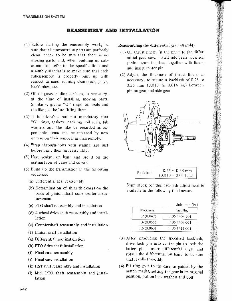
Reassembling the pinion shaft
1) Insert the shims (which have been selected on the basis of cone center measurement) between the circlip and the outer race of tapered roller bearing in the wall of transmission case.
2) Insert pinion shaft (to rear end of which tapered roller bearing and c1ic1ip have been mounted) into transmission case through
c
TRANSMISSION SYSTEM
corresponding one formed of case. The long holder comes on the right side, and the short one on the left.
its rear end. At the same time, insert pinion C shaft into the gear 31-20T.
3) Set the circ1ip to the groove on the front portion of the pinion shaft, and secure gear 31-20T.
4) Install the bearing holder, ball bearing, tab washer, and lock nut in order, and adjust the lock nut so that the specified preload on the pinion shaft can be obtained. Rend the tab washer to secure the lock nut.
Coun tershaft preload
'J C J J J r
0.07 ~ 0.08 kg-m (0.51 ~ 0.58 ft-lb)
c
Installing the differential gear assembly
(1) The differential gear assembly is already in built-up condition at this stage, complete with the ring gear. Lower it into transmission case, with the ring gear coming on the left side.
(2) Position the two bearing holders (differing in length) in place, seating each holder correctly by matching its notch to the
[NOTE] Bear in mind that, if the holders are
not positioned correctly as dictated by the matching notches, interference occurs between final gear and bearing holder. The final case might break if the case is secured under this condition (interference between holder and gear.)
(3) Tentatively tighten the two bearing holders in place, right and left, on transmission case, making their securing bolts snug-tight. Be sure that stopper washers are used on these bolts.
(4) Using the below-indicated sizes (thicknesses) of shim stock (liner), adjust the ring gear backlash to the specification in the manner hereunder described:
0.25 ~ 0.35 mm Ring gear backlash (0.01 ~ 0.014 in.)
Shim stock for ring gear backlash adjustment Unit: mm (in.)
Thickness Part No.
0.2 (0.008) 1135 1419000
0.3 (0.012) 11351421000
0.5 (0.020) 1135 1422 000
5-45

TRANSMISSION SYSTEM
5-46
(a) Insert the liner between transmission case and left-side bearing holder. Be sure that the individual shims (each consisting of one or more sheets) of the liner are equal in thickness. This requirement is met by using the same number of shim sheets. The liner here is tentative and need not be exact in thickness, but make sure that the clearance is filled up uniformly all around.
(b) Tighten the left-side holder (which is now sided by the tentative liner) good and hard, but leave the right-side holder in snug-tight condition. Take a backlash reading, as shown, to see if the backlash is within the specified range indicated above; if not, loosen the left-side holder and increase or decrease the thickness of the liner there.
(c) A proper backlash having been secured, measure the clearance between the rightside holder and case, and fill the clearance with another liner equal in thickness to the reading. This liner, too, is to be formed in the same way as above. Put on stopper washers and tighten the rightside holder.
(d) Tap lightly on the differential gear case in place, directing the tapping force leftward and rightward to be sure that this case has no end play. Re-check the backlash and, upon noting that it is within the specified range, lock the bolts securing the bearing holders, right and left, by bending stopper washers sharply. The holder bolts are to be tightened to this torque value:
Tightening torque 2.5 ~ 3.0 kg-m (18 ~ 22 ft-Ib)
Installing the PTO drive shaft
Set the circlip to PTO drive shaft, and install the spring retainer, spring clutch (B), bushing clutch (A) in order to PTO drive shaft. Connect PTO drive shaft and shaft 18-IIT with the coupling.
Bushing
Clutch (B)
/ PTO drive shaft Spring
Col
/ Liner
8al/ beal>il
/ Ge

d 3), ft. :h
In
Reassembling and installing the final case
(1) Grease oil seals, and fit the seals to those parts of final case admitting differential shaft and final shaft. For the final shaft, however, a washer must be installed before fitting the oil seal.
(2) Press ball bearing onto differential shaft. Grease "0" ring and fit it to oil seal collar. Feed the collar onto differential shaft, with its "0" ring coming next to the ball bearing.
(3) Insert differential shaft into final case, and set it in place by fitting circlip.
(4) Position final shaft in final case, fit ball bearing by pressing, and retain the bearing by installing circlip.
[NOTE] When forcing the bearing in, be sure
to apply the push to its inner race.
Ball bearing
Differential
==~&:::l1~~rru=)j[~fF~(jjl- shaft Oil seal
Circiips
TRANSMISSION SYSTEM
(5) Install circlip (for final gear stopper) on final shaft, mount final gear and collar, and press in ball bearing.
(6) Take two measurements: 1) height of ball bearing face above the seat formed of transmission case for final case, and 2)
distance from transmission case face to ball bearing holder. On the basis of these two measurements, determine the shim (liner) thickness necessary for giving an end play of 0.12 to 0.4 mm (0.005 to 0.016 in.) to final shaft. The liner with the determined thickness is to be used on ball bearing holder.
Final shaft end play
Shim
0.12 ~ 0.4 mm (0.005 ~ 0.016 in.)
r-H*- End play
(7) Apply sealant to the mating face of final case, fit the case to transmission case, and secure it by tightening its bolts to this torque value:
Tightening torque
[NOTE]
5.0 ~ 6.0 kg-m (36 ~ 43 ft-lb)
The right-side final case must be complete with differential lock shifter and lock sleeve: the shifter must be installed before inserting differential shaft into the case.
5-47

TRANSMISSION SYSTEM
Reassembling and installing HST unit
Assemble and install HST unit according to the following procedure.
[NOTE] Before assembling the parts, wash them with
cleaning oil. Do not assemble the parts in dirty or dusty place. Assemble them on a clean table.
1) Install the left and right check valves to the valve block, and install the valve block ass'yto the valve plate holder with the hexagon socket head bolts.
/ ~v Valve plate holder Valve block
~ 0 ~
'[IJ c a
0
w~ It: [NOTE)
Be sure to install O-ripg to the valve block before assembly.
2) Clean disassembled parts of neutral valve. Clean the bore of valve body as well. Spool should move smoothly in the case when installed in it (to the extent that falls down with own weight).
3) Assemble the neutral valve in reverse order of the disassem bly procedure.
[NOTE] Do not insert the plate too deeply but leave
it to the extent that collar, spring, etc. will be pushed in when valve plug is tightened. V-groove of plate should come inside.
4) Install the low pressure relie f valve to the valve plate holder.
S) Assemble the parts into the high pressure
5-48
relief valve ass'y at first, and then, install the high pressure relief valve ass'y to the valve plate holder.
) a
High pressure relief valve ass' y
6) Install the bearing to the driving shaft, and install them to the casing. Install the plate from the inside of the casing with two hexagon socket head bolts.
Casing
Driving shaft
o
7) Install the pin and HST control shaft from the outside of the casing, and secure the swash plate with spring pin.
/
9

(NOTE) On HST control shaft side, two spring pins are
used.
8) Install the bearing to the driven shaft, and install them to the casing body, and then, install the sliding plate. Secure the sliding plate from the outsude of the casing with the hexagon socket head bolts.
Sliding platE:;
9) Install the oil seal and a-ring to the oil seal holder, and install them to the casing (on both of driving shaft and driven shaft).
TRANSMISSION SYSTEM
f}
10) Secure the oil seal holder with the circlip (on both of driving shaft and driven shaft).
11) Assemble the rotating part assembly.
a) Insert the jig into the cylinder block, and push in three pins.
5-49

TRANSMISSION SYSTEM
b) Assemble the knuckle.
Knuckle
c) Place the piston and retainer.
Retainer
Piston
Jig
Rotating part ass'y
d) After assembling the rotating part assembly, pull out the jig slowly, and install the rotating part assembly to the driving shaft and the driven shaft.
5-50
() o
Rotating part ass'y
12) Fit the needle bearing to the valve plate holder forcedly.
\~
[NOTE) Confirm that the bearing is projected 3mm
(0.1 inch) from the surface of the valve plate holder.
13) Fit the valve plate (L) to the needle bearing on the driving shaft side, and the valve plate to the needle bearing on the driven shaft side.
/
15)

g 'y
)ld-
--
mm late
ring late ide.
TRANSMISSION SYSTEM
Valve plate (L) Valve plate 16) Install the vane to the driving shaft.
c
[NOTE] Only one side of the valve plate (L) on the '@
driving shaft is notched.
14) Apply sealant to the fitting faces of the casing and valve plate holder.
o (J ()
15) Assemble the valve plate holder ass'y and the casing ass'y.
~ ';!# -0=----
o
[NOTE] Assemble the vane and rotor with their point
marks toward the casing side of the charge pump.
17) Install the oil seal cover, bearing, and rotor to the casign, and isntall them to the driving shaft.
[NOTE] After disassembling and reassembling, take
the record of serial No. on the name plate of HST unit.
5-51

TRANSM ISSION SYSTEM
o o Name plate 0
C
18) Apply sealant to the fitting faces of HST unit and the transmission case, and assemble them.
Reassembling the mid PTO shaft
Install the ball bearing and gear l5T to the 4-wheel drive shaft in order from the front of HST unit. Install the ball bearing to HST unit. Assem ble the mid PTO shaft, and install gear 33T and ball bearing in order to the shaft. Then, install the ball bearing to gear 15T on the 4-wheel drive shaft side, a:q.d install the bearing holder, on which the oil seal has been isntalled , with six bolts.
Driving shaft
Gear 33T
'JAlI-----\-jI-lJ-- G ea r 1 5 T
5-52
LINK ADJUSTING PROCEDURES FOR NEUTRAL POSITION OF HST
1. With @ removed, separate the control link and HST control lever @ .
2. Make sure that ball is properly in the neutral position set plate hole (2) .
3. Start engine and place sub-shift lever in L. Then gradually raise engine speed from to high speed.
4. If tractor moves forward or backward, return the engine to idling speed and with three bolts @ loosened, move the control shaft level'
back and forth, and stop it at approximate center of neutral zone, then tighten three bolts evenly.
[NOTE] Lever should be operated by hand with the ball properly remaining in plate hole. It should not be operated with excessive force that causes the ball to fall out of the fall.
5. Run the engine at high speed again to make sure that the tractor stands still.
6. If it still moves, repeat adjustment per step (4) above.
7. Place HST foot control pedal in neutral position.
8. Interlock adjust rod A and control shaft lever by means of @. Adjust rod length with nut ® loosened so that rod A has equal amount of play in front and back.
9. For interlocking with hand control level', place hand lever in neutral position of the lever guide and adjust the length of rod B with the nut <P loosened so that interlocking holes are aligned.
[NOTE) External View-Right Side shows the link
under manual operation.
H
1)
a)
UBi
leal Wh vah

1
Right side view]
HST control hand lever 2 Nut 3 Nut 4 Joint 5 Backward speed adjusting stopper 6 HST control lever 7 Poppet ball case 8 HST lever set bolt 9 Neutral position set plate
10 Set plate attaching bolt 11 HST control shaft 12 Neutral valve plug (R.H)
How to measure hydraulic pressure
The qaulity of HST unit can be judged by measuring the hydraulic pressure for the pump in HST unit.
1) Measuring hydraulic pressure in neutral valve
a) When settingHST control lever to the forward position, remove the plug, and install the high pressure gauge [Measuring range to be 0 -350kg/cm2 (4978psi)] to right side of the neutral valve. Install the low pressure gauge [Measuring range to be 0 - 40kg/cm2 (568.8 psi)] to left side.
[NOTE] When installing the pressure gauges to HST
unit, be sure use sealing tape to prevent oil leakage. When measuring on high pressure side of neutral valve:
TRANSMISSION SYSTEM
i) Apply the parking brake to secure the tractor.
ii) Set the engine speed to 1,000rpm, and move HST control lever toward forward position slowly.
iii) Watch the engine speed, and read the hydraulic pressure when the engine speed starts to lower.
Hydraulic pressure at high pressure side of neutral valve
265 ~ 290 kg/cm2
(3769 ~ 4125 psi.)
When measuring on low pressure side of neutral valve:
i) Apply the parking brake to secure the tractor.
ii) Set the sub gear shift lever to neutral, and set the engine speed to 2,600 - 2,700rpm. Read the pressure gauge at this point.
Hydraulic pressure at low pressure side of neutral valve
4 ~ 6 kg/cm2
(56.9 ~ 85.3 psi.)
b) When setting HST control lever to the reverse position, the high and low pressure sides are reversed. Therefore, the pressure gauges must be installed in opposite way to the forward position. The hydraulic pressure on the high and low pressure sides can be measured as described in a).
[NOTE] The pressure gauges must be set to the correct
positions, and HST control lever must be moved correctly.
If the low pressure gauge is set to high pressure side, it may be damaged.
2) Measuring the suction pressure of charge pump.
Remove HST inlet pipe from HST unit. Remove the union bolt, and install the
5·53

TRANSMISSION SYSTEM
5-54
pressure gauge instead using the adapter B (Measuring range to be -1 to 1.5 kg/cm2 (-14.2 to 21.3 psi»). Apply the parking brake to secure the tractor, and set the sub gear shift lever to neutral, and then start the engine. Set the engine speed to 2,600 - 2,700rpm, and read the suction pressure.
Suction pressure
of charge pum'p
-0.2 kg/cm2 or more
(-2.84 psi or more)
® ,,-------Pack ing
®
~ Nipple" .
~ Seal Coupling
~Joint
• Hose
8 Measuring tools
~ P ressu re gau ge
"""-Coupler: X Forward
Hose
(HST unit, R.H.)
(HST unit, L.H.)
Piping for measuring the hydraulic pressure
TRANSMISSION SYSTEM
[STARTING-UP THE HST TRACTOR AND TROUBLE SHOOTING]
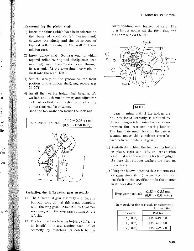
Engine starting and travelling procedures
No. OPERATION RESULT
1 Place sub-shift in neutral Turn on the start safety switch
2 Open throttle fully Engine gets ready for start (Fuel injection increases)
3 Depress clutch all the way HST driving load not applied
4 Turn on starter switch Cranks the engine
5 After engine has started, return throttle lever to (For safety purpose) 1 000 ~ low idling range
6 Slowly return clutch pedal Drives HST
7 Run the engine as it is for Supplys oil to HST circuit and 3 ~ 5 mimutes waits for air to escape
8 Disengage clutch and move Power train connected to axle su b-shift lever to L or H (HST drive is off)
9 Return clytch pedal (Drive HST)
10 Increase engine speed (Secures required drive force)
appropriately
11 Moving HST lever slowly forward causes the tractor HST power transmitted to travel forward. (Vice-versa)
12 To bring tractor to stop, return HST lever to neutral. HST is brought to neutral and (Returning it suddenly stops.
causes jerky stopping)
Remark: Stops 6 and 7 may be skipped unless it is immediately after an oil replacement. (Example: After pipe has been removed or filter has been replaced.)
5-55

0'1 Checking procedures to follow if tractor does not move ~
0, :0 » m Z C/)
s:: CD @ ® @ @ Hoil illter
C/) C/)
If sub-shi ft IfHST contro! I ftransmission IfHST suction is installe d Tighten properly 0 ... .. ... pipe is tigh t- .. properly? c:) Z
isprq>erly link is p roper- oil lever is _._---------- C/) ene d su fficien t- ------------ Replace oil filter -< enga!Jld? ly functioning? proper? ly (finnly) ? If oil illter is C/)
not clog!Jld ? ~ m
D D D 1] I s::
Shift it again Adjust link Replenish with Tighten properly ® oil If other piping>
are properly tightened? I c==> I Tighten properly (O-ringprotuded .. and damaged? Any oil leak ? )
c::::> (YDisassembly and
I inspection are
c::> Return troubled required. HST to dealer Replace HST by (j) unit Ifvalve plugs
t or blind plugs I c:::::::) I Tighten properly on HST are pro-perly tightened?
Checkings down to step 10 can be carried out @ Ifhigh pres- @) Ifneutral I externally. However, improper handling 0 f step
sure relief 9 will result in necessity 0 f disassembling the valve is not .. valve is not HST. (See "[5] HST NEUTRAL VALVE clog!Jld with clogged or ® DISASSEMBLING AND REASSEMBLING") dust? sticking? .. If flow pressure
Steps 3 ~ 7 are the troubles caused with
D D regulating valve is not
air taken in. clogged with dust or scuffed?
Disassemble, clean Disassemble, clean
D and reinstall. and reinstall. (Be care ful in (Be care ful in disassembling) disassemblin g)
I Disassemble, clean and reiustall

Cf1 .01
-..J
Trouble shooting
TROUBLE CHECKING PROCEDURE
l. Operating HST control lever does not cause Check in accordance with procedures shown in "[2] CHECKING PROCEDURES TO FOLLOW IF TRACTOR tractor to move. DOES NOT MOVE"
2. Tractor travels but does not again speed. I Is link lever properlyJ (OK~~I;2J(OK)~!gn matte~1~I~ST control lever shaft I tightened? _ ........ deformed? ....... in linkage? loosened
~ ~ ~ -~-, Adjust or retighten.' 'Correct or replace. I I Remove it. I I Retighten. I
3. Does not travel normally (travels and stops Check in accordance with steps ~d down shown in against intention).
4. Stops by slight load. CD Check in accordance with steps @ ~ (j) in [2]. * (Engine speed does not drop but HST noise gets @IfOK, check with [2] @Q~><V, in that order.
greater and stops.) Note) If adjustment is proper and air has not been taken in, it is highly probable that dust is in the high pressure safety valve.
5. Travels only in one direction, (forward or reverse) , Check the control link , -----+ 'Disassemble- and check the spool valve. (for dust or sticking) ,
~ ~ I Ti ten, adjust I I Clean and relative I 6. Even ifHST co trollever is moved slowly Same as above 5_
tractor makes jerky start only.
7. Does not stop even with HST control lever 1 With HST control lever in neutral,? 1 (OK) .1 Remove external link and
r 1 (NO) Disassemble and check ssool
returned to neutral. is control lever poppet ball on ---+ loosen?eide plate oflever ~ valve. After cleaning an HST case end properly in its hole? on HS end, and adjust_ reinstallation, adjust in
J. reversed procedure. '(External link adjustment) I
8. Vibration betwenn charge pump and filter or CD Check in accordance with steps [2] @ ~ (j) . HST noise is great. Note) If it has been working normally until just before, clogging of oil filter is suspectable.
9. Oil temperature increases. I Oil cooler}O d I (OK). I Fan belt loosended I (OK~ I Oil cooler damaged (OK! I Ask dealer for disassembly I Radiator ogge --+ or damaged.. --+ or clogged.. --+ and repair of HST_
~ ~ ~ I Oean I I Adjust tension or I I Clean or replace. ,
replace.
Remarks: *l. In case setting location of control lever is close to neutral position, travelling speed may fall or tractor may stop due to travelling load. If such is the case, adjust the speed by moving the HST control lever toward the direction where the speed increases_ (Change oftravelling speed according to load is the characteristics of HST and does not represent any trouble.)
- - ---
1-3 "1 o §. -l'D
[IJ
=o o .... .... = IJtl
--I :JJ » Z (I)
s: (I) (I)
(5 Z (I)
-< ~ m s:

CHAPTER 6
BRAKE SYSTEM
ISO


....
TABLE OF CONTENTS Page
Description ... . . . . . . . . . . . . . . . . . . . . . . . . . . . . . . . . . . . . . . . . . . . . .. 6-1
Construction ............................................... 6-2
Disassembly ................................................. 6-3
Inspection and maintenance ................................... 6-5
Reassembly ................................................. 6-6
Adjustment . . . . . . . . . . . . . . . . . . . . . . . . . . . . . . . . . . . . . . . . . . . . . . . .. 6-7
Troubleshooting ............................................. 6-8
Specifications ............................................... 6-9


BRAKE SYSTEM
DESCRIPTION
The brake system for the MITSUBISHI MTI60/D, MT180/D and MTI80H/HD is of a mechanical internal expansion type.
When the foot pedal is depressed, a cam rotates, the brake lining is pressed against the inside of the brake drum and brake is applied. Brakes are installed in right and left final cases.
Two brake pedals are provided to brake right and left wheels independently. It is an essential requirement for an agricultural tractor that one wheel can be locked completely to make a sharp turn in a confined space or in the corner of the field. Both right and left wheels can be braked at the.same time by linking right and left brake pedals with a connecting plate.
The brake drum is installed on the differential shaft which rotates at higher speed than the rear wheels do, to ensure high braking efficiency.
High braking efficiency both in forward and reverse is also provided by its internal expansion type structure where the lining of brake shoe is pressed against the inside of the brake drum by means of the cam.
The brake system is completely enclosed, which eliminates trouble due to water or dust even when the tractor works in paddy fields or velY dusty places.
6-1

BRAKE SYSTEM
CONSTRUCTION
The brake drum is installed at the end of the differential shaft mounted on the differential side gear. In the middle of the shaft, a gear is provided to drive a final shaft.
The brake drum is covered with a brake cover attached to the final case and completely enclosed in the brake cover in which the brake shoe is incorporated.
Anchor pin, cam shaft and brake shoe with a lining are fitted to the brake cover. Brake cam arm is installed in the outside of the brake cover to rotate the cam. The brake pedal is fitted to the cross shaft mounted on the lower part of
Final gear
6-2
the clutch housing. Brake cam arm and brake pedal are connected by brake rod and when the pedal is depressed, the cam is rotated via the brake cam arm and the lining is pressed against the brake drum, thus brake is applied.
When the connecting plate is released, right and left wheels can be braked independently and used selectively depending on the work and field conditions.
Parking brake is applied by connecting right and left brake pedals with the connecting plate and lock the brake pedals with the parking brake lever on the clutch housing side.
Brake cam
Differential shaft
Brake drum
Brake shoe

BRAKE SYSTEM
DISASSEMBLY
Disassembling the brake cover and brake drum
Place a jack under the transmission case and take up the weight of the case with the jack to such an extent that the rear wheels will become slightly airborne. Apply parking brake, and loosen rear wheel bolts; remove the rear wheels and release the parking brake.
(I) Remove brake rod from brake cam shaft.
(2) Loosen the six M8 X 20 bolts securing the brake cover, and remove the cover.
(3) Remove circlip on differential shaft.
(4) Remove brake drum.
(5) Remove brake shoes from brake cover, as required.
[NOTE] To replace differential-shaft oil seals
and ball bearings, remove final case from transmission case in order to permit their replacement. How to remove the final case is explained in "Disassem bly of the final case."
6-3

BRAKE SYSTEM
(6) Remove circlip on cam shaft, and take off cam shaft.
Return spring
Brake shoe
,! 1 ,I r~.iJ? ' ~
0(1 _ ~ ~ (I .::0.. (I
o.:ng~ ~ B"k, com ,h'ft (LH(~
Packing
Circiip
Disassembling the brake pedals
If brake pedals alone have to be removed, it is not necessary to remove both steps, right and left: remove the right-side step only. The lefthand step, too, must be removed if brake cross shaft is to be disassembled.
(I) Remove brake cam and brake rod.
(2) Pick out circlip on the right-hand end of brake cross shaft, and remove brake pedal on the right.
6-4
(3) Draw out spring pin from left-hand brake pedal, and remove brake pedal.
(4) Remove brake cross shaft by drawing it out to the left.
J

BRAKE SYSTEM
INSPECTION AND MAINTENANCE
(I) Check the brake cam shaft O-ring, and if scratched, replace.
(5) Check the brake cam shaft for excessive wear.
(6) Check the return spring for fatigue. (2) If the brake shoe is excessively worn, replace.
(3) Check for oil or grease on the brake shoe.
(4) Check the oil seal for oil leakage.
(7) Check the brake cross shaft and brake pedal for rust or streaks.
Inspection Maintenance
Worn brake lining If the thickness of lining is more than 2.5 mm (0.10 in.), use it again.
Uneven brake lining contact Grind the surface.
Oil on brake lining If only· a little, correct it with sandpaper.
Brake drum If it is scarred, grind it.
Return spring
Brake pedal free play
Parking brake
Oil leakage in brake
Foreign particles in drum
Adjust it with brake rod.
Apply oil to ensure that lock plate operates properly.
Check it for leaking parts.
Check "0" ring and packing
Service limit
If it is less than 2.5 mm (0.10 in.), replace.
If it is 2.5 mm (0.10 in.) in thickness after grinding, replace.
If a lot of oil is attached, replace the shoes.
If the drum inner diameter exceeds 114.5 mm (4.508 in.), replace.
If it is weakened, replace.
20 ~ 30 mm (0.79 ~ 1.18 in.)
If oil seal is faulty, replace it.
If "0" ring and packing are faulty, replace them.
6-5

BRAKE SYSTEM
REASSEMBLY
Reassemblying the brake drum and brake cover
(1) Install greased O-ring to the cam shaft, and apply grease to the grease groove. Install the cam to the brake cover, and set it with the circ1ip.
(2) Hook the spring to the brake shoes and install them to the brake cover.
(3) Install the brake drum to the differential shaft, and set it with the circ1ip.
(4) Fit packing to brake cover; place the cover on final case, move cam shaft to spread out brake shoes against drum; and, while centering brake cover, tighten bolts to this torque value:
Tightening torque
6-6
2.0 ~ 2.5 kg-m (14 ~ 18 ft-lb)
Reassembling the brake pedals
(1) Grease the brake cross shaft mounting boss under the c1u tch housing, and insert the brake cross shaft into the boss.
(2) Push in the left-side brake pedal, and install the spring pin.
(3) Push in the right side brake pedal, and install the circlip.
(4) Install both right- and left-side brake rods, and set them with cotter pins.
(5) Install the step, and install the return spring.
[NOTE] Make sure that brake pedals move
smoothly.
(.

BRAKE SYSTEM
ADJUSTMENT
Adjusting the brake pedals
Free play of the brake pedal must be maintained within the correct range, otherwise, accidents may occur or power will be lost.
Before the brake on one side becomes unadjustable even by means of brake rod, caused by
(l) Loosen lock nut and rotate the joint piece to produce a free play of 20 to 30 mm (0.79 to 1.18 in.) at the brake pedal. With this much play obtained, tighten the lock nut.
(2) Confirm that the right and left brakes operate simultaneously by running the tractor. If not, adjust both of them by means of the brake rod.
(3) Make sure that the parking brake operates correctly.
premature wear of the brake lining due to its more frequent use than the other, periodically interchange the right and left brake shoes. Special care should be taken in the case where the brake on one side only is frequently used.
Joint
-----1-1 ! .. ---l
Lock nut
6·7

BRAKE SYSTEM
TROUBLESHOOTING
Poor braking
Possible cause Remedy
Too much pedal free play Adjust with brake rod.
Worn brake lining Adjust with brake rod ?r replace brake shoes.
Uneven lining contact Grind with sandpaper.
Burn t lining Replace brake shoes.
Oil on brake lining Repair oil leakage and replace brake shoes.
Brakes remain ON
Possible cause Remedy
Not enough pedal free play Adjust with brake rod.
Loose brake spring Replace.
Loose return spring Replace.
Cross shaft and holder sticking Disassemble, correct and apply grease.
Brake shoes seized with rusts Remove rusts.
Abnonnal noise
Possible cause Remedy
Defective brake cover centering Loosen bolts securing cover, and retighten them while moving cam lever.
Foreign particles in drum Clear away.
Damaged lining Replace brake shoes.
Damaged retU1:n spring Replace.
Brake shoes seized with rusts Remove rusts.
6-8

Type
Brake pedal
Parking brake
Lining material
Lining dimension (length X width X thickness)
Number of linings
Drum inner diameter
Braking position
Brake pedal free play
BRAKE SYSTEM
SPECIFICATIONS
Foot operating internal expansion water-proof dry type
Separate with interlocking device, foot operating type
Main brake used hand operating lock type
Specially woven fabric
119x 28.5X 4.0 mm (4.7 X 1.12X 0.16 in.)
4
114 +g.1 mm (4.49 +g.004 in.)
Differential shaft
20 ~ 30 mm (0.79 ~ 1.18 in.)
6-9


ISO
CHAPTER 7 ... 1
HY AULIC SYSTEM


TABLE OF CONTENTS
Description ............................................... .
Construction ...................... . ,', .................... .
Operating principles ......................................... .
Hydraulic power take-off for external service ..................... .
Page
7-1
7-2
7-3
7-6
Hydraulic case assembly ...................................... 7-7
Hydraulic pipes and oil filter .................................. 7-13
Oil pun1p . . . . . . . . . . . . . . . . . . . . . . . . . . . . . . . . . . . . . . . . . . . . . . . . .. 7-15
Adjustment ................................................ 7-19
Troubleshooting ........................................ . . .. 7-20
Specifications .............................................. 7-22

I .
I
I
HYDRAULIC SYSTEM
DESCRIPTION
The hydraulic system in MITSUBISHI MT 160 and MT 160D is simple in construction; its operation is accurately controlled form an easy-te-operate contro11ever.
For the source of hydraulic pressure, a gear pump of pressure-balanced type is used. The pump is mounted on the timing gear case of the engine, and is driven through gears inside the case. Thus, as long as the engine is running, hydraulic pressure is available.
For the hydraulic actuator to raise and lower the hitched implement, such as the rotary and ploW, a single-acting cylinder is used.
It is the oil in the transmission case that the oil pump draws and delivers to the hydraulic circuit. A high-performance oil filter keeps the oil clean for the hydraulic system. A provision is made in the discharge side of the pump to make the pressurized oil available for driving an external hydraulic device, a feature made possible by the high capacity of the pump.
The hydraulic control valve is a three-way spool valve and, as such, is a precision-machined component. It is a compact unit installed in the hydraulic case. The lowering speed control lever is installed on the cylinder head of the hydraulic case.
The control lever is so linked to the lift arm that, when the hitched implement reaches a certian elevation in lifting action, the lever returns by itself to its neutral position, thereby unloading the pump.
There is no need to drain the transmission in order to permit removal of the hydraulic case.
7-1

HYDRAULIC SYSTEM
CONSTRUCTION
Cylinder head "0" ring
Adjuster
Plate
Schematic diagram of hydraulic system
The oil pump draws oil in the transmission oil sump through the oil' filter. The discharge line of the pump is tied to the oil inlet of the control valve.
In the control valve, oil from the pump is directed to the hydraulic cylinder or to the return line, depending on the position of the spool.
Moving the control lever to "LIFT" position directs the oil to the hydraulic cylinder to push out its piston, whose outward movement is transmitted through piston rod to the lift fork. This fork then rotates the ram shaft to turn up the lift <arm, thereby lifting the hitched implement.
As the lift arm rises to a predetermined elevation, another arm (auto-return arm) pulls back the control lever to "NEUTRAL" through a link rod; and when this occurs, the spool traps the oil in the line extending to the hydraulic cylinder, so that the lift arm is prevented from turning down, thereby holding the hitched implement in lifted position.
7-2
With the spool in "NEUTRAL," the incoming oil returns to the transmission and the pump runs in no-load condition.
Moving the control lever to "DOWN" position pushes the spool all the way, communicating the hydraulic cylinder to another return line. Consequently, the piston (on which the weight of the implement is acting through the arms) moves inward to force the oil out. The displaced oil flows through the flow control valve and returns to the transmission oil sump. In other words, "DOWN" motion is gravity but "braked" by the flow control valve.
As an optional feature, another control valve may be provided elsewhere, preferably at the hitched implement to drive an additional hydraulic ram.
And also an additional single-acting hydraulic ram can be provided and operated from the hydraulic control valve. These are what are referred to as an external service.

HYDRAULIC SYSTEM
OPERATING PRINCIPLES
NEUTRAL With the spool in "NEUTRAL" position,
pressurized oil enters control valve through port A and returns to the transmission case through port C. All return oil is spread from the return line to the piston rod and ram shaft to lubricate them.
Port B is blocked by the spool land, so that the oil in the line to the hydraulic cylinder remains trapped. Thus, the hitched implement is held rigidly in its current vertical position. Needless to say, the pump under this condition supports no load.
7-3

HYDRAULIC SYSTEM
LIFT
With the spool in "LIFT" position, port C is blocked while port B is opened, The oil pushes on the piston in the hydraulic; cylinder to do the work already explained.
As the hitched implement rises to the limited elevation, the spool gets pulled back by the control lever as actuated through linkage· from the auto-return arm, and halts at "NEUTRAL" position.
7-4
In the event the hitched implement offers abnormally large resistance to the lifting force, oil pressure in the pump discharge line will build up or peak. In such a case, excess pressure is bled out through port D in the safety valve.
\
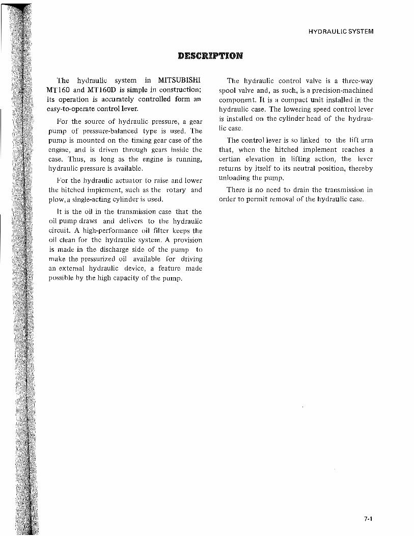
DOWN Moving the control lever forward, that is, to
"DOWN" relocates the spool to communicate port B to port E, keeping port C open to allow the discharged oil to return to the sump in the transmission. As explained previously, the oil flows out of the hydraulic cylinder through the flow control valve (acting like a brake) and returns through port E to the sump, so that the hitched implement goes down by its own weight.
HYDRAULIC SYSTEM
7-5
j

HYDRAULIC SYSTEM
HYDRAULIC POWER TAKE·OFF FOR EXTERNAL SERVICE
There are two ways as under on the hydraulic external service. Select it according to the kind of control valve attached to the implement.
[NOTE] External service cannot be done for the
machine which is equipped with control valve for use of 3-point linkage of tractor.
Hydraulic case
Spacer
Adaptor
Rei ief valve cover
Remove the cover (relief valve) on the left side of hydraulic case and secure the spacer, adaptor plate and cover to the hydraulic case. Pass a hose or pipe to IN port of the control valve installed on the implement side from OUT port of the adaptor plate. Pass a hose or pipe to IN port of the adaptor from OUT port of the control valve to make a hydraulic circuit. The implement can be operated by acuating the lever of control valve attached to the implement.
7-6
PT3/S "--"'~-
PT3/S Adapter
~. __ ._J Spiicer
Transmission case
[NOTE]
Hydraulic pump
1) Thread size of adaptor plate is PT-3/8.;
2) In order to do the hydraulic external service, never use the external port located in the hydraulic cylinder head as it may cause trouble in the hydraulic system.

HYDRAULIC SYSTEM
HYDRAULIC CASE ASSEMBLY
Causes necessitating hydraulic system disassembly may be regarded as occurring in three areas: 1) hydraulic case, in which the control valve is mounted, 2) oil pump, and 3) oil piping inclusive of the oil filter.
Whenever trouble develops, a rough check must be made on each area to pinpoint the suspected part or component. Disassembly of parts and components in sound condition should be avoided and can be avoided by viewing the hydraulic system as consisting of the three groups.
Disassembling the hydraulic case
It is not necessary to drain the transmission in order to permit removal of the hydraulic case.
(I) Remove seat and tool box.
(2) Remove fender bracket and left-had cover.
(3) Remove union bolt securing the pimp press~ie pipe to hydraulic case.
Union bolt
(4) Remove 8 bolts securing the hydraulic case to transmission case, and take off the case.
T ransm issi on case
[NOTE] Because of sealant used in the joint of
hydraulic case and transmission case, the hydraulic case may not come off easily; if so, loosen the joint by poking with the tip ·of plain screwdriver, taking care not to damage the case, and remove it by lifting it straight off. Remember, the hydraulic case is made of an aluminum alloy and is not so resistant to shock load as are steel or cast-iron parts.
(5) Straighten the lock plate under the heads of bolts securing the control valve, loosen the bolts and remove the control valve. Be sure to pick out "0" ring.
7-7

HYDRAULIC SYSTEM
Bolts
(6) Pull off cotter pin from the tip of control lever to free the auto-return feedback rod, loosen the bolt on the right-side lift arm, and remove the feedback rod.
(7) Remove right-side lift arm. Loosen the bolt on the left-side lift arm, and remove this arm, too.
7·8
(8) Remove the bushing set bolts, move ram shaft to and fro by driving on its two ends alternately and remove bushings and oil seals. Draw ram shaft out.
(NOTE] When pulling ram shaft out, hold the
lift fork by hand so that the shaft comes off smoothly.
(9) Remove lift fork and piston rod.
(0) Loosen MlO bolts on cylinder head, and remove the head.
Cylinder head Hydrau I ic case
(11) Push piston out into hydraulic case, and take out piston.
(2) Loosen the nuts on plate and arm by which control lever is held in place, remove the plate and arm, and take off control lever.
Disassembling the control valve
The control valve is a precision-machined component and should not be disassembled in the field unless its disassembly is absolutely necessary. Select a clean place, free from any dust, to perform its disassembly. Upon removal of its spool, exercise utmost care not to damage it even in the slightest way. The bore, too, must be similarly protected. Be sure to adhere to the following instructions:
• If the spool is found in defective condition to require replacement, replace the valve body, too. The spool and body must be handled as a set.
11
thl
re\ th~

i
e
:d In :sto itS
it be he
to ly, as
.. Do not disassemble the safety valve unless a facility for measuring oil pressure is available. This is because, after its reassembly, it must be tested and set for the specified relieving pressure.
5 4 6 8
The disassembling procedure is as follows:
(1) Pick out circlip on that end of spool opposite to the part where spring pin is fitted, and draw the spool out of the body.
(2) Loosen the lock on the lock nut of safety valve, and remove the lock nut.
7
(3) Loosen relief adjuster, and take out spring, spring retainer and ball.
(4) Drive valve seat off the body by lightly tapping on the seat from outer side.
Inspection of control valve
(1) Inspect valve seat and seating face of steel ball for damage. Be sure that the seat and seating face are both p,erfectly free of any dent, nick or scratch mark.
(2) Inspect spool and bore for evidence of scuffing, galling, etc.
Reassembling the control valve
Have all parts washed clean and dried. Oil them and reassemble in sequential order which is reverse of disassembling sequence, making sure that no part picks up dust.
HYDRAULIC SYSTEM
9
1-Spool
2-Circlip
3-Spring pin
4-Lock nut 5-Rel ief adjuster 6-Spring 7-Steel ball
8-Spring retainer 9-Valve seat
The specified relieving pressure for the safety valve is 135 kg/cm2 (1920 psi) in full-flow condition.
Disassembling the cylinder head
After removing the cylinder head from hydraulic case, proceed as follows:
(1) Remove nut securing the knob, lightly tap on the knob and remove it from the tapered portion of adjuster.
(2) Remove the adjuster.
(3) Pick out circlip, and take out spring and steel ball.
( 4) As necessary, rem ove "0" rings.
7-9

HYDRAULIC SYSTEM
4
-~~~lt~~~~~~~gal=: 13 1 .. __ -12
7
1-Cylinder head 6-"0" ring 2-Grip 7-Plug 3-Adjuster 8-"0" ring 4-Nut 9-"0" ring 5-Spring washer
1-1---11 ~~~
10-Steel ball 11-Spring
12-Washer 13-Circlip
10
Reassembling the hydraulic case
When reassembling the hydraulic case, the following steps must be taken.
• Thoroughly wash all parts with cleaning oil.
o Blow all washed parts with compressed air to dry them. Do not use cloth to wipe them.
• As for valves and related parts, they should be kept dipped in gear oil SAE #80 after being washed.
• Avoid re-using "0" rings, backup ring and gaskets. Always use new ones. Before installing "0" rings, coat them with good quality grease. Apply grease sparingly.
• Always use new cotter pins.
• Do not put on gloves while reassembling operations.
• Before starting reassembly, make sure that the place is clean.
e When re-using the used oil after reassembly is over, avoid using the lower part of the oil. Add new oil to make up for the amount of discarded oil (about one-tenth of the total oil amount).
• Do not stretch "0" rings so that they will not permanently deformed.
7·10
The reassembling procedure is as follows:
(I) Connect the piston rod to lift fork and set with cotter pin.
(2) Place lift fork in hydraulic case, and align the punch mark on ram shaft to the punch mark on lift fork.
1-Ram shaft 2-Lift fork
3-Punch mark
(3) Hold the bushing with its chamfered side facing inward, and put set bolt into bushing while paying attention to the set bolt position.
Secure ram shaft by tightening set bolt (around which a seal tape is wound) from the top of the case.
Tightening torque 6.0 ~ 7.0 kg-m
(43.3 ~ 50.6 ft-Ib)
(4) Grease oil seal, and tap it in until it contacts the bushing.
(5) Install backup ring (fully damped with oil) and "0" ring to the piston.
Oil the cylinder, and install piston.

"0" ring Backup ring
(6) Reassemble cylinder head as follows:
[NOTE] If the plug has been removed, be
sure to wrap it with sealing tape or to apply sealant to it before re-fitting. Make certain that neither pieces of sealing tape nor crumby particles of sealant, whichever is the case, will not get into oil.
(a) Grease "0" rings, and fit them to adjuster, setting the rings neatly in the groove.
(b) Run adjuster into cylinder head.
(c) Grease "0" ring, and fit the ring to the front side of culinder head.
(d) Into cylinder head, insert steel ball, followed by spring and washer, and put on circlip.
(e) Grease large "0" ring, and fit it to cylinder head.
HYDRAULIC SYSTEM
(7) Fit small "0" ring to the cylinder head thus far assembled, position it in hydraulic case and secure it by tightening its bolts to this torque value:
Tightening torque 8.5 ~ 9.5 kg-m (61 ~ 68 ft-lb)
(8) Attach the grip, in which spring pin has been inserted, to adjuster, put on spring washer and fasten it down tentatively by tightening its nut snugly.
(9) Grease oil seal and fit it to that part of hydraulic case for holding control lever, and install control lever.
(10) Fit arm, plate and lock washer, in that order, to control lever, and secure them by tightening the nut. Lock the nut.
(11) Fit "0" ring to control valve, insert spool, and position the spool in such a way that the spring pin in the forward end of spool will fit into the notch provided in the arm and plate of control lever.
(12) Put on lock plate, taking into account the direction of spring, and secure the control valve by tightening the bolts to this torque value:
Tightening torque 2.5 ~ 3.0 kg-m (18 ~ 22 ft-lb)
Lock the bolts with lock plate.
7·11

HYDRAULIC SYSTEM
(13) If the lube oil pipe for lift forks has been disconnected from the rear end of control valve, reconnect the pipe by running it in about 7 to 9 mm (0.28 to 0.35 in.) or by an amount equal to 5 or 6 threads, and tighten the lock nut with the pipe hole pointing to the lift fork center.
Control 7 ~ 9 mm Pipe valve (0.28 ~ 0.35 in.)
Tool
(14) If the lever has been removed from control lever, check to be sure, after installing the lever, that the lever moved to the front and rear meets a stop and that .the distances from the "NEUTRAL" position of the lever to the "LIFT" position and to the "DOWN" position are equal.
Rod
(15) Install two lift arms, right and left, positioning both arms to align their match marks to the punch marks provided on ram shaft. Attach auto-return arm to the rightside lift arm, and tighten the bolt to this torque value:
Tightening torque 5.0 ~ 6.0 kg-m (36 ~ 43 ft-Ib)
(16) Connect auto return rod to control lever and to the arm attached to the right-hand end of ram shaft, and lock the connections by inserting cotter pins. Fit collar and spring to the rear side of rod and make the two nuts snug-tight temporarily.
(17) Fit "0" ring to the plate, position the plate and cap on the left-hand side of hydraulic case, and secure them by tightening to this torque value:
Tightening torque 2.5 ~ 3.0 kg-m (18 ~ 22 ft-lb)
(18) Clean the seat (for hydraulic case) on transmission case, apply the sealant to the cleaned seat, and fit hydraulic case to the seat. Secure the case by tightening its bolts to this torque value:
Tightening torque 5.0 ~ 6.0 kg-m (36 ~ 43 ft-lb)
(19) If top link bracket has been removed, install it.
tl o
p

HYDRAULIC SYSTEM
HYDRAULIC PIPES AND OIL FILTER
Removing the discharge pipe
Hydraulic oil (transmission oil) need not be drained out to carry out this removal. When the discharge pipe comes off, oil in it will spill out: be sure to catch this oil with a proper receptacle.
Oil pump
(1) Remove pipe clamp on the left-hand side of clutch housing.
(2) At the same side, loosen union bolt on the left-hand side of hydraulic case and leave it screwed in just a few threads.
(3) Remove 4 bolts securing the pressure pipe to the underside of oil pump. Be sure to pick out "0" ring.
(4) Take off the union bplt mentioned above, and sever pressure pipe. Be sure to recover seal washers.
Removing the suction pipe
It is necessary to drain hydraulic oil, making the transmission empty of oil, in order to carry out this removal. Drain by removing the drain plug on the bottom of transmission case.
( 1) Remove step board on the left.
(2) Remove pipe clamp on the left-hand side of clutch housing.
~
Clutch housi~g 11 n
/'
Union bolt
Oil filter
(3) At the same side, remove union bolt on the left-hand side of hydraulic case securing the pressure pipe, and take off seal washers.
(4) Open the bonnet.
(5) Remove safety cover on the left.
(6) Disconnect suction pipe from the lower left-hand part of transmission case by removing its bolts.
(7) Similarly disconnect suction pipe from the above oil pump.
Removing the oil filter
Have hydraulic oil (transmission oil) drained out, and remove bolts securing the oil filter to transmission case at its lower right-hand part. The oil filter can now be taken out.
7-13

HYDRAULIC SYSTEM
Inspection of oil filter
(1) Do not re-use "0" rings, seal washers and the like that have been removed in disassembly unless they are in perfectly good condition. It is advisable to use new ones when reconnecting the pipes.
(2) Inspect the connecting ends of each pipe and also the full length of pipe. Be sure that pipes are free of any evidence of cracks and their connecting end faces are smooth and free from any damage. Cracked pipes must be replaced. Repair or replace pipes whose ends are in faulty condition.
(3) Inspect the filtering element (gauze-like element) of the oil filter for signs of rupture and, as necessary, replace the element.
Installing the pipes
Before installing a pipe, be sure to have "0" rings and seal washers ready for use if they are needed for the pipe. Some pipe connections need such sealing parts while others do not.
The reconnecting procedure is reverse of the removal procedure for each pipe, and install the pipes, starting with the one last removed.
When positioning the oil filter in place, check to be sure that its forward end is accurately attached to the suction pipe.
7-14
Tighten connections to the following torque values:
Suction pipe at pump 1.0 ~ 1.2 kg-m
(7.0 ~ 8.7 ft-lb)
Suction pipe at 2.5 ~ 3.0 kg-m transmission (18 ~ 22 ft-lb)
Pressure pipe at pump 1.0 ~ 1.2 kg-m
(7.0 ~ 8.7 ft-lb)
Pressure pipe at 4.5 ~ 5.5 kg-m hydraulic case (33 ~ 40 ft-lb)
Oil filter 2.5 ~ 3.0 kg-m (18 ~ 22 ft-lb)

HYDRAULIC SYSTEM
OIL PUMP
Construction This oil pump [Nachi-GP-3607 A] is of the
gear type, employing the pressure loading system. The pressurized oil is forced out to the rear side of bearing bushing, and the minimum clearance is maintained between the gear teeth and bushing to minimize internal leakage, thereby securing a high volumetric efficiency even at high-pressure-Iow-speed operation. (The bearing bushing serves as a pressure loading component and casing at the same time.) The bearing bushing is of movable design, and, as a result, it is able to maintain a proper clearance whether the bushing swells due to heat or is worn due to protracted low-temperature operation.
The bearing bushing is designed to be lubri cated by low pressure oil which is forced fed, independently of the pressurized oil on the outlet side. This pre~ents the seizing-up of the bearing and the damage of the oil seal.
As far as the oil is clean, 90 percent of the specified volumetric efficiency can be secured for a long period. The pump has been tested for 4000 hours continuous operation and proven to maintain high-performance.
o ~I Outlet
(NOTE] a) The pump oil seal is made of synthetic
resin, and therefore, mineral oil should be used for lubrication. Use of acid and alkaline oil, kerosene, and high octane vegetable oil is not allowed. Extremely high temperature oil may cause corrosion to the oil seal.
b) The oil should be gear oil SAE 80. For details, refer to the lnstruction Book.
Removal
Hydraulic oil (transmission oil) need not be drained out for this removal.
( I) Open the bonnet.
(2) Remove safety cover on the left.
(3) Loosen bolts securing pressure and suction pipe connections. Recover "0" rings.
(4) Loosen nuts securing the pump to timing gear case, and take out the pump.
7-15
HYDRAULIC SYSTEM
Disassembly
[NOTE) The oil pump should be disassembled
iJ:! a clean place, and the tools must be also clean. All disassembled parts are blown with compressed air for drying, after being washed. Do not use rags.
Take care not to damage the body and cover, because they are made of aluminum alloys.
For this disassembly work, refer to the exploded view.
(1) Loosen the bolt (L) with a hexagon hole, and remove the cover (J) and "0" ring (I).
(2) Push the drive gear (D) into the body (A), and the bushing (F) can easily be taken out by finger. Remove the bushing (F), and remove the drive gear (D) and driven gear (E). The bushing (C) can be take out together with the "0" ring (B).
F
J G I K
\ ~a ~ : ~ \
a H ~I
Inspection
Replacement of worn or damaged parts should be done with special care. In order to increase pumping efficiency, the gear rotates with its teeth in slight contact with the pump casing. The contact is evidenced on the low pressure side of the pump. After a long period of use, the oil will become dirty, and bushing holes and journal bearings will be worn. As a result, the
7-16
The disassembled parts should be arranged in order. As for the shafts and bushings, their positions should be correctly memorized.
When installing bushings, take care not to confuse the bushing (C) for bushing (F) in relation to' their positions.
Each bushing has a mark A or C stamped on its end. A bushing having mark A shouW be installed on the cover side. (e.g. A indicates clockwise rotation, and C denotes counterclockwise rotation.) The oil ~eal (M) should not be removed unless otherwise broken. When pulling out the oil seal (M) from the body, take special care not to scratch the housing bore.
A-Body B-"O" ring C-Bus.hing "A" D-Drlve gear E-Driven gear F-Bushing "C"
G "0" ring H "0" ring I -"0" ring J.-Cover K -Washer L-Bolt M-Oil seal
casing wllll begins to show wear. If the amount of wear exceeds 0.05 mm (0.002 in.), the clearance between the gear teeth and the casing wall will be excessive, and oil leakage will increase. This will reduce the performance of the pump. Replacing the bushing will not be effective to improve the performance. The use of a worn bushing is not recommended except when the pump is operated under low pressure and with special care.

In general, working parts are subject to wear after a long period of use, and there will be not a big difference in wear between them. It is advisable, therefore, that when any component parts show an excessive wear, the pump itself should be replaced, instead of replacing worn parts. It will be more economical.
Each part should be washed with kerosene and blown with compressed air. All removed "0" rings should also be replaced. Check the gears and gear shafts for scratches and broken teeth. The contact ratio in a pair of gears in mesh should be even. Measure the shaft diameter with an outside micrometer calipers. If the measurement shows a smaller value than Nachi -Y3.96 mm (0.550 in.) ,replace the shaft.
Check the bushings for deformed bore and scratches. If any discoloring of a gear can be considered to be related with a defective bushing, check for the relief valve and related oil passages. If the length of a bushing is shorter than the value as shown below, it should be replaced.
I 16.80 mm (0.661 in.) I Any discolored gear should also be replaced.
Measure the clearance between the shaft and bushing. If the measurement is larger than the following value, the bushing should be replaced.
I 0.177 mm (0.006 in.) I Reassembly
Make sure that all parts are clean. If the oil seal (M) has been removed, it should be replaced. To install the oil seal, use a press. (The seal lip must face inward.)
(1) Place the "0" ring (B) on the bushing (C), and coat it with good quality of mineral grease. Insert it in the body (A) and push it in further. A pair of bushings must be true and coat it with good quality of oil. Insert it in the body (A) and push it in further. A pair of bushings must be true fitted in place without requiring force. If the bushing has a scratch on its surface, it
HYDRAULIC SYSTEM
will not move smoothly. In this case, pull out the bushing and smooth down the raised part with oil stone. Make sure that the surface of the bushing is smooth. For this check, use a surface plate. After using oil stone, be sure to wash the bushing. Oiling the bore will make it easy to install the bushing. Make sure that, after installation, the "0" rings are in place.
The "0" ring must be located between the bushing and the bottom of body. The leading gear type is greatly affected by the result of reassembly. Make sure that the escape groove in the bushing surface is not inclined. Incorrect reassem bly will not provide the pressure balance effect, and as a result, the bushing in the bore will be deformed by pressure.
(2) When inserting the drive gear (D) into the body (A), take care not to damage the oil seal with the stepped (machined) part of the gear shaft. Insert the drive gear (D) and the. driven gear (E) into the body (A).
(3) Fully grease the bushings (F) in pair, and insert them in the body. Place the "0" rings (H) on the bushing (F).
(4) Place the "0" rings (G) and (I) on the cover, and place the cover, Finally tighten the bolt (L) with a hole by using a hexagon wrench. Tightening torque is 0.8 kg-m (5.77 ft-lb). Lock the bolt head with center punch and feed a small quantity of oil through the port.
(5) Make sure that the reassembly is done perfectly by turning the drive gear (D) with an open end wrench. If the gear turns smoothly, the assembly is correct. If too tight, correct it.
7-17

HYDRAULIC SYSTEM
Installation
(1) Align the pump shaft with the pump drive shaft, and install it to the engine timing gear case.
(2) Set the "0" ring correctly, and install the suction pipe and delivery pipe to the pump.
Test
Special care should be taken for test run, particularly when bushings, gears and body have been replaced. Test run should be continued at least for 30 minutes. First, make sure that the engine oil, cooling water, transmission oil and other components of the tractor are all perfect. Run the engine with no-load at idling speed, and when oil temperature rises as specified (engine water 82° C or 180° F), increase the engine speed to increase the pump delivery. Operate the control lever for hydraulic control, and give load to the pump.
7-18
In particular, while operating the pump, check the temperature of the pump. If the temperature is excessively high (about 80°C or 176°F), reduce the engine speed temporarily, and continue no-load operation until working parts are fully run in.
[NOTE )
The disassembly and reassembly of the pump are relatively easy, but it should not be unnecessarily disassembled because of trouble of the hydraulic system, of which causes are unknown. Avoid performing disassembly for repair in the field, because it is very difficult to prevent dust and dirt from entering the pump. Parts may also be scratched.

HYDRAULIC SYSTEM
ADJUSTMENT
The hydraulic mechanism of BEAVER m and BUCK tractors is so designed that when the implement is moved up to the highest position of full stroke, the hydraulic control lever moves back to the neutral position automatically. If the control lever will not return, as above, after reassembly, adjust as follows:
(1) Disconnect the lift rod from the lift arm.
(2) Turn the flow control grip all the way coun terclockwise.
(3) Run in the nut on the auto-return rod until the control lever automatically returns to "NEUTRAL" position and, with the lever in that position, the lift arm has a free play of 5 ~ 15 mm (3/16 ~ 19/32 in.) as measured at the tip of the arm, as shown below.
(4) Where it is necessary to limit the end of upward stroke of lift arm to any desired height, run in the nut until the control lever automatically returns to "NEUTRAL" position when the arm reaches the desired height.
Rod
Flow control grip
Loosen nut securing the flow control grip: this nut is in snug-tight condition. Remove the grip, and run in the adjuster all the way by turning it clockwise. Restore the girp, positioning it in such a way that its spring pin meets the clockwise end of the pin guide groove provided in the cylinder head. With the grip so positioned, put on spring washers and secure the grip by tightening the nut.
Start up the engine, and check to be sure that the grip is at locking position when the hitched implement is raised by operating the control lever. With the grip at this position, move the control lever to "DOWN" and see if the hitched implement refuses to go down and stays in its current raised position; if not, that is, if the implement goes down, it means that the adjuster is set improperly and needs to be repositioned further in clockwise direction. The grip is properly set when the hitched implement becomes held up under the above operating conditions.
Quick 'i':'::;':!.:~ Lock
Adjusting grip
7-19
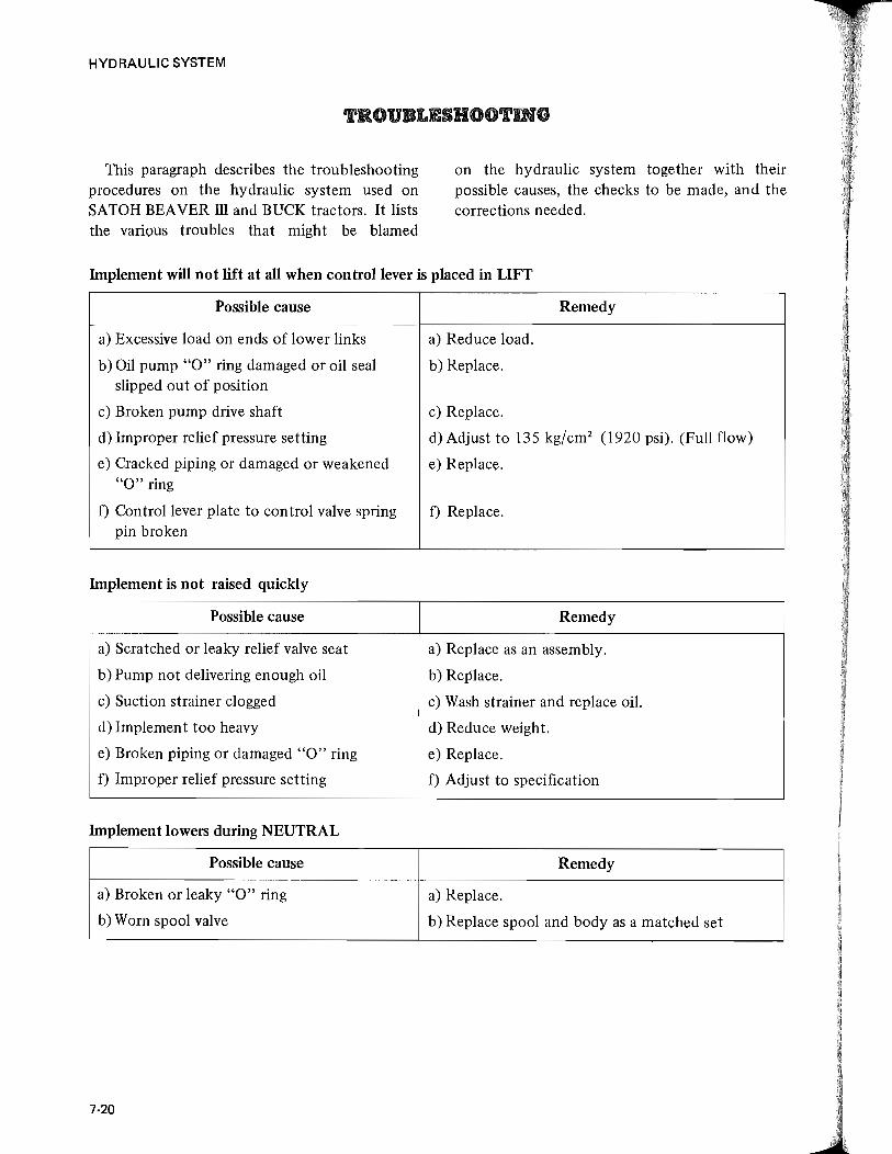
HYDRAULIC SYSTEM
TROUBLESHOOTING
This paragraph describes the troubleshooting procedures on the hydraulic system used on SATOH BEAVER ill and BUCK tractors. It lists the various troubles that might be blamed
on the hydraulic system together with their possible causes, the checks to be made, and the corrections needed.
Implement will not lift at all when control lever is placed in LIFT
Possible cause Remedy
a) Excessive load on ends of lower links a) Reduce load.
b) Oil pump "0" ring damaged or oil seal b) Replace. slipped out of position
c) Broken pump drive shaft c) Replace.
d) Improper relief pressure setting d) Adjust to 135 kg/cm2 (1920 psi). (Full flow)
e) Cracked piping or damaged or weakened e) Replace. "0" ring
f) Control lever plate to control valve spring f) Replace. pin broken
Implement is not raised quickly
Possible cause Remedy
a) Scratched or leaky relief valve seat a) Replace as an assembly.
b) Pump not delivering enough oil b) Replace.
c) Suction strainer clogged c) Wash strainer and replace oil.
d) Implement too heavy d) Reduce weight.
e) Broken piping or damaged "0" ring e) Replace.
f) Improper relief pressure setting f) Adjust to specification
Implement lowers during NEUTRAL
Possible cause Remedy
a) Broken or leaky "0" ring a) Replace.
b) Worn spool valve b) Replace spool and body as a matched set
7-20

HYDRAULIC SYSTEM
Implement will not lower when control lever is placed in DOWN
Possible cause
a) Flow control valve kept closed due to loosened lock nut
b) Flow control lever not properly set
Oil temperature is excessively high
Possible cause
a) Oil pump seized
b) Pump not delivering enough oil
c) Relief valve at fault
d) Leaking relief valve seat due to damage
e) Relief valve stuck open
Abnormal noise
Possible cause
a) Pump seized
b) Pump not sucking enough oil
c) Air leaking into suction pipe or past oil seal
d) Deteriorated oil
e) Clogged strainer
d) Relief valve stuck open
Remedy
a) Readjust and secure with lock nut positively
b) Readjust.
Remedy
a) Replace. (Check for presence of foreign particles in oil)
b) Replace.
c) Adjust to 135 kg/cm2 (1920 psi).
d) Replace.
e) Readjust auto-return.
Remedy
a) Replace.
b) Check oil level in tank or clogged suction filter.
c) Repair.
d) Replace.
e) Clean.
d) Readjust auto-return.
7-21

HYDRAULIC SYSTEM
SPECIFICATIONS
~ Specification MTl60 and MTl60D
Control 3-position control -lift, hold, down and flow control
Type of cylinder Single action cylinder
Diameter of piston 60 mm (2.36 in.)
Stroke of piston 71 mm (2.80 in.)
Pressure for relief valve setting 135 kg/cm2 (1920 psi)
Maximum lift power at ends of lower 500 kg (1102lb) links
Type of hydraulic pump Pressure loading gear type
Output of hydraulic pump l2.9liter/min. (at 2700 engine rpm) (3.4 GPM)
Control valve type Spool valve 3-port 3-position
Name and model of hydraulic pump NACHI: GP - 3607A
Oil lock valve Oil lock valve (adjustable flow control)
Strainer mesh #42 X 100 mesh
Hydraulic oil SAE #80 gear oil (same as transmission oil)
External service PT3/8 tap
Hydraulic adaptor plate Optional
7-22

ISO
CHAPTER 7
HY AULIC SYSTEM
(Position Control)

------------------------------------------...

TABLE OF CONTENTS
Page Description ................................................ 7-25
Construction .............................................. 7 -26 Operation
•••••••••• I •• , • -. •••••••••••••••••••••••••••••••• 7-29 Disassembly and reassembly .................................. 7-33
Oil pump. . . . . . . . . . . . . . . . . . . . . . . . . . . . . . . . . . . . . . . . . . . . . . . . .. 7-49
Adjustment. . . . . . . . . . . . . . . . . . . . . . . . . . . . . . . . . . . . . . . . . . . . . . .. 7-53
Troubleshooting ............................................ 7-56
Specifications .............................................. 7-59


HYDRAULIC SYSTEM
DESCRIPTION
The hydraulic system in MITSUBISHI MTl80jD and MTl80HjHD is unique in design, compact in size. Its component parts are built in a single case.
The functions the system provides are position control, flow control and lift lock. By installing sub control valve or adaptor plate, hydraulic pressure can be taken off for external service.
The hydraulic pump is mounted on the timing gear case of the engine, and is driven through gears inside the case. Thus, as long as the engine is running, hydraulic pressure is available for actuating the implement.
It is the oil in the hydraulic case that the pump draws through the strainer and delivers to the control valve.
The lift lock valve is mounted on the front side of hydraulic case. By operating its control lever, the implement can be locked and its lowering speed can be adjusted.
Hydraulic pressure can be taken off for external selVice by installing the adaptor plate between the hydraulic case cover and reliefvalve installed on the left side of hydraulic case.
7·25
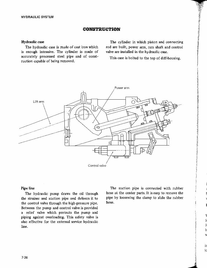
HYDRAULIC SYSTEM
CONSTRUCTION
Hydraulic case The hydraulic case is made of cast iron which
is enough intensive. The cylinder is made of accurately processed steel pipe and of construction capable of being removed.
Lift arm
The cylinder in which piston and connecting rod are built, power arm, ram shaft and control valve are installed in the hydraulic case.
This case is bolted to the top of diff-housing.
Power arm
Control valve
Pipe line
The hydraulic pump draws the oil through the strainer and suction pipe and delivers it to the control valve through the high-pressure pipe. Between the pump and control valve is provided a relief valve which protects the pump and piping against overloading, This safety valve is also effective for the external service hydraulic line.
7-26
The suction pipe is connected with rubber hose at the center parts. It is easy to remove the pipe by loosening the clamp to slide the rubber hose.
e b v
I
'" Ie Ii b: w
in 10

Oil cooler
Control valve
Oil pump
Oil pump
Cooler outlet pipe
The control valve is mounted under the hydraulic lift lock valve and has a linkage connected to the control lever. In this valve are built the spool valves, check valve, unloader valve and poppet.
Lift lock valve
The lift lock valve is an in-line check valve. When the oil enters the cylitider, it pushes the lock valve to open. Once the oil enters the cylinder, it forces the lock valve against the seat by means of the pressure generated by the weight of the implement and spring pressure.
Accordingly, the heavier the weight of the implement, the greater the pressure against the lock valve. While in farming operations, the lock
HYDRAULIC SYSTEM
Oil filter
Oil filter
HST inlet pipe
valve opening can be easily adjusted by the lever. This makes it possible to regulate the implement lowering speed ranging from "slow down" (while seeding) to "quick down" (while plowing).
Cylinder head "0" ring
Spring
7-27

HYDRAULIC SYSTEM
Control lever
The control lever is mounted on the right side of hydraulic case. By operating it as guided by the quadrant mounted on the fender, the control linkage is moved to perform control function.
Position control lever
Feed back link
Hydraulic pump
A high-efficiency gear pump of pressure loading gear type is used. The pump is mounted on the engine timing gear case, and, as long as the engine is running, it delivers the oil to the control valve. Thus, the hydraulic system of MITSUBISHI tractor is live type.
7-28
~
Control valve
Feed back arm
I I
I
~

HYDRAULIC SYSTEM
OPERATION
POSITION CONTROL LIFT
After engine starts, move the position control lever in the direction of raising
up, and the spool valve (1) of control valve
Control val be
LIFT
To cylinder ~::::1~---..J
Check valve
Unloader valve From pump
moves in the direction of raising up by the action of valve shifter fixed at link
lever shaft which is connected with link lever on the left side of the hydraulic case.
Poppet
t-e---Plate
Spool valve
- NEUTRAL position)n LIFT
7-29

HYDRAULIC SYSTEM
The oil from the pump flows to the rear side (A) of unloader valve (6) through the passage (B). Then the pressure of this oil and the force of spring (7) close the unloader valve (6). Under this condition, the oil pushes down the check valve (4) and enters the circuit (D) leading to the cylinder.
The implement is lifted up by the action of the lift arm as the piston is pushed down by
filling the cylinder with oil The spool valve (1) is
returned to NEUTRAL position by the action of the feed back shifter through the feed back arm HL which is moved by the feed back HL rod as the arm installed at the lift arm works. Consequently, the implement is held at the position where corresponds to the position of control lever.
Feed back shifter
Joint
Control valve
NEUTRAL
Check valve-
Unloader valve
7·30
C
To tank
Plate
Spool valve
NEUTRAL position

NEUTRAL
The oil from the pump flows through the passage (B) in the control valve to the unloader valve (6). The check valve (4) is kept in closed position by the force of its spring (5) and the pressure exerted by the weight of implement mounted on the 3-point linkage, which are applied to the rear side (C) of the valve (4). For this reason, the return circuit from the cylinder is blocked to hold the implement. On the other hand, the rear side (A) of unloader valve (6) is connected through the spool valve (1) to the tank, and as the pressure of the oil from
Lever link arm
HYDRAULIC SYSTEM
the pump is higher than the pressure exerted by the unloader valve spring (7) the oil pushes down unload valve (6) to open the tank port, thus returning the oil to the tank, which makes the pump operate unloaded.
DOWN In case the control lever is located at the
position of DOWN, the spool of unloader valve (6) moves in the direction of opening by the action of valve shifter on the link lever shaft connected with the link lever.
Control valve Joint
DOWN
To tank
From cylinder L-I=L_":::::; 1---- Plate
Check valve --~~~~~~~t~
Valve spool
NEUTRAL position - DOWN From pump
7-31

HYDRAULIC SYSTEM
Now the poppet (2) is pulled by the plate locked to the spool valve (1) to open the port (D) leading to the tank, causing the oil to flow into the tank port for loweripg the implement.
When the implement starts to go down, the spool valve (1) is returned to NEUTRAL position by the action of feed back shifter through the feed back arm which is moved by the feed back rod as the arm installed at the lift arm works.
The implement is held at the position where the spool valve is located at NEUTRAL.
Hydraulic case
Spacer
Adaptor
Relief valve cover
Hydraulic external service
There are two ways as under on the hydraulic external service. Select it according to the kind of control valve attached to the implement.
[NOTE] External service cannot be done for the
machine which is equipped with control valve for use of 3-point linkage of tractor.
PT3/8 lkJI'~_
PT3/8
-,---,---' _____ J
Transmission case
Adapter
Hydraulic pump
Hydraulic circuit for front loader, etc.
Remove the cover (reliefvalve) on the left side of hydraulic case and secure the spacer, adaptor plate and cover to the hydraulic case. Pass a hose or pipe to IN port of the control valve installed on the implement side from OUT port of the adaptor plate. Pass a hose or pipe to IN port of the adaptor from OUT port of the control valve to make a hydraulic circuit. The implement can be operated by acuating the lever of control valve attached to the implement.
7-32
[NOTE) 1) Thread size of adaptor plate is PT-3/8.
2) In order to do the hydraulic external service, never use the ex ternal port located in the hydraulic cylinder head as it may cause trouble in the hydraulic system.

e e
HYDRAULIC SYSTEM
DISASSEMBL Y AND REASSEMBLY
Disassembling the hydraulic system
Causes necessitating hydraulic system disassembly may be regarded as occurring in three areas: 1) hydraulic case, in which the control valve is mounted, 2) oil pump, and 3) oil piping inclusive of the oil filter.
Whenever trouble develops, a rough check must be made on each area to pinpoint the suspected part or component. Disassembly of parts and components in sound condition should be avoided and can be avoided by viewing the hydraulic system as consisting of the three groups.
Disassembling the hydraulic case
It is not necessary to drain the transmission in order to permit removal of the hydraulic case.
(1) Remove the 3-point linkage from tractor.
(2) Remove the seat.
(3) Disconnect wirings from each connector. (4) Remove the knobs from the control lever. (5) Unscrew bolts both of the left and right
that fasten the fender to the step and the cover to the step.
(6) Remove the tool box by means of loosening four tool box fixing bolts.
(7) Remove fenders.
(8) To remove the pipe from the hydraulic case, loosen the union bolt of the pressure pipe.
Union bolt
[NOTE] As the union bolt heat is not thick
enough, be sure to use socket wrench. Using open wrench will give damage to union bolt head.
(9) Loosen the bolts securing the hydraulic case to the diff-housing, and remove the hydraulic case assembly.
Hydraulic case
T ransm ission case
7-33

HYDRAULIC SYSTEM
[NOTE] Because of sealant used in the joint
of hydraulic case and diff-housing, the hydraulic case may not come off easily;
Disassembling the hydraulic control linkage
/
I-Control lever 9-Cotter pin
2-Levee bracket 10-Link lever
3-0il seal II-Lever link arm
4-Lock nut 12-Plate
S-Valve shifter 13-Feed back arm
6-Spring pin 14-E-type circlip 7 -Feed back shifter IS-Joint pin 8-Link lever shaft 16- Feed back rod
7-34
If so, loosen the joint by poking with the tip of plain screwdriver, taking care not to damage the case, and remove it by lifting it straight off.
17-Joint 18-Plate 19-Collar 20-Washer 21-Disk spring 22-Washer 23-Washer 24-Plate
@ \
l-e 2-" 3-F 4-V S-C

(1) Loosen the lock nuts (4) at the end of control lever (1) and link lever shaft (8). Remove the assembly oflink lever shaft (8), link lever (10) and lever fink arm (11).
(2) Pull out the cotter pin (9) of plate (18) at the right side of arm shaft and remove the joint(17).
(3) Pull, out the spring pin (6) that connects the feed back arm (13) with feed back shifter (7). Remove the related parts from the feed back rod (16) as required.
(4) Pull out the control lever (1). And remove the assembly of feed back
arm (13) and feed back rod (16).
(5) Remove the feed back shifter.
[NOTE] Remove the oil seal and other parts from
the hydraulic case as required.
Removing the control valve
(1) Pull out the cotter pin (6) of clevis pin (5) which sets the valve link (4) to the fork (3) and then take out clevis pin (5).
I-Control valve 2-"0" ring 3-Fork 4-Valve link 5-Clevis pin
6-Cotter pin 7-Nut g-Pipe 9-Spacer
IO-Bolt
II-Lock washer 12-Nut 13-Taper plug 14-Washer
HYDRAULIC SYSTEM
(2) Straighten the lock plate (9) under the heads of bolt (10) securing the control valve (1), loosen the bolt (0) and remove the control valve (1). Be sure to pick out "0" rings (2).
(3) Unlock the lock washer (11), loosen nut (12) and remove fork (3).
Removing the power arm
(1) After loosening bolts (19) of lift arms (13), remove both lift arms(13) and washers (16).
(2) Loosen bushing set bolts (21), and then remove oil seals (3) and bushings (10).
(3) Remove the ram shaft (6).
(4) Remove the power arm (7) keeping it incorporated a piston rod (17).
(5) Remove the piston rod (17) from the power arm (7) as required.
7-35

HYDRAULIC SYSTEM
1 -Hydraulic case 2-Bolt (MlO x 4S) w/washer 3-0il seal 4-Plug S-Dowel pin 6-Ram shaft 7-Power arm 8-Spring washer
9-0-ring 10-Bushing 11 -"0" ring 12-Back up ring 13-Lift arm 14-Cotter pin IS-Bolt (MlOxlOO) I6-Washer
17 -Piston rod I8-Plate 19-Bolt w/spring washer (M10x2S) 20-Cylinder 2I-Bushing set balt 22-Washer 23-Seal washer
Remov:ing the lift lock valve Disassembling the cylinder (1) LOQsen M 12 bolts on cylinder head, and
remove the head.
Cylinder head Hydraulic case
(2) Push piston out into hydraulic case, and take out piston.
(3) Remove the lift lock valve as required.
7-36
Remove the hydraulic cylinder from hydraulic case while paying attention to "0" rings.

Disassembling the control valve The hydraulic system including the control
valve is almost trouble-free if the oil filter is cleaned and the oil is changed at the specified intervals.
Should the control valve become defective, disassemble it in a clean place in a careful manner.
® l-Body 2-Unloader valve 3-Spool valve 4-Piate
[NOTE)
5-Nut 6-Valve seat plug 7-Poppet 8-Valve seat plug
Before disassembling the control valve,
HYDRAULIC SYSTEM
@II Disassembling
Remove the control valve from the hydraulic case, and proceed as follows:
(1) Remove nut (5) and the valve seat plug (6) with 26 mm socket.
(2) Remove valve seat plug (8) and plate (9).
(3) Pull out the spool valve (3) and poppet (7) to the left hand side.
(NOTE) As the plug and seat head is not thick
enough, be sure to use box wrench. Using open wrench will give damage to plu~ and seat head.
.. Inspection
(1) Wash the disassembled parts in cleaning oil and dry them with air. Correct or replace defective parts with scratches or damages.
(2) Be sure to replace the body and spool as a set. All the other parts can be replaced as a single piece each.
• Assembling
Be sure to replace "0" rings with new ones. When assembling, apply clean oil and assemble carefully. Pay a special attention to the inclination of the spring and movement of each valve.
measure the body and plate, and make a 17 note of the measurements which will be 16 \\
used when reassembling the control valve. 1 4 1 5 \ \ ~
13 \ ~ ® \@\7 20 12\\ ~~ ~ h ~
6 17 ~vi~ 18
5 \ ~~'- I-Body assembly
3 4 ,,; .. ~'~ ~ 1 ;:~~::j:.atPIUg \ ~ ()~~21 i~;:;~;t
2 (.) V / I \ ~1 6-"0" ring
~~ - 10 7-Backupring
..- §;5 ~ d'\' / 3 8-Valve seat plug / :&J 9-Spool valve ~ lO-Spring »> 19 8
ll-Unloader valve 12-Spring 13-Check valve 14-"0" ring IS-Seat plug 16-Plate 17-Nut 18-Stopper plate 19-Plate 20-"0" ring 21-Retum spring
7-37
4

HYDRAULlC SYSTEM
(1) Fit an "0" ring and back-up ring to the poppet and install the poppet to the body together with a spring. Fit an "0" ring to the seat and install it to the body with plate (21). Install the "0" ring to the poppet side and back-up ring to the screw side.
Tightening torque 7""" 9 kg-m (50.6,...., 65.0 ft-lb)
(2) Fit art "0" ring to the check valve seat. Install the spring first and then check valve and fasten with a seat plug. Lock the seat plug after punching.
Tightening torque 5""" 7 kg-m
(36.1 ,...., 50.6 ft-lb)
(3) Install the plate to the spool valve, install a stopper plate and fork fasten with a nut.
Tightening torque 1.2,...., 2.2 kg-m
(8.684,...., 15.9 ft-lb)
(4) Insert the spool valve into the body, and install the plate to the poppet. Set the body and plate according to the measurements taken before disassembly, and tighten the nut.
(5) Install the unloader valve.
• Control valve adjustment
~--\-----i -ht-0.3 - 0.6 mm 1(0.012,...., 0.024 in.)
Air¢:= UP
Nut
Air ¢:= NEUTRAL~~~~~~~J-TC~
Unloader valve
7-38
(1) With the unloader valve installed, blow air into the unloader plug hole.
(2) Insert the thickness gauge, as shown in figure between the plate and the double nut, and confirm the followings:
(a) When inserting the thickness gauge of 0.3 mm (0.1 in.), air comes out of the hole C of the spool valve - at NEUTRAL position.
(b) When inserting the thickness gauge of 0.6 mm (0.2 in.) air comes out of the pump port D, or no air leakage is noticed anywhere - at UP position.
(3) If such a case is not applicable, loosen the double nut and adjust it so as to meet the requirement shown by the item (a) and (b).
(4) In case of adjusting, punch the outer nut for preventing looseness after finishing adjustment.
(5) Insert the spring into the unloader valve and tighten the plug with "0" ring.
Tightening torque
Prunp relief valve (cover)
7,...., 9 kg-m (50.6,...., 65.0 ft-lb)
Pump relief valve is installed in the pipe line connected to the pump and control valve. It has been designed to operate properly even when a sub control valve is installed.

t
~
e
ne las la
fit Relief valve (disassembling the cover)
When the relief valve is disassembled completely, pressure should be adjusted. Never disassemble it without special reason.
After removing the hydraulic case, proceed as follows:
(1) Remove the plug, and take out the shim, "0" ring, spring seat, spring, poppet and valve seat.
(2) Pressure can be adjusted by changing the thickness of the shims.
Relief set pressure
• Inspection
135 kg/cm2
(1920 psi)
Wash the components in cleaning oil and inspect it carefully for damages. Replace with new one if a remarkable flaw is found. Especially check the poppet and seat face carefully.
ED Assembling
Wash components cleanly to remove dust or dirt. Check to see that no damage is involved, apply oil and assemble carefully.
Be sure to replace "0" rings with new ones, and apply grease thinly before assembly.
Fit an "0" ring to the plug, install a seat, poppet and then spring to the body. Install a spring seat to the plug and mount it to the cover.
HYDRAULIC SYSTEM
• Relief set pressure adjustment
If the relief set pressure is less or more than the specified, or the cover is disassembled, it is necessary to measure the relief pressure. If no measuring facilities are available, measurement can be taken with the valve installed. For measurement, proceed as follows:
(1) Install a compression gauge to the 1/8 tap of the hydraulic case cover.
(2) Start the engine, move the control lever over the finger guide toward LIFT so that the relief valve is actuated. Read the pressure gauge. If the pressure is high, decrease the thickness of the shim. If low, increase the shim thickness. Pressure will change.
Shim
~ ~(J Poppet ~ I.@ \
Cov" Plog "~~ "0" ciog
1 ~ SWing
Valve seat
7-39

HYDRAULIC SYSTEM
Reassembling the hydraulic case
When reassembling the hydraulic case, the following steps must be taken.
• Thoroughly wash all parts with cleaning oil.
• Blow all washed parts with compressed air to dry them. Do not use cloth to wipe them.
e As for valves and related parts, they should be kept dipped in gear oil SAE 80 after being washed .
.. Avoid re-using "0" rings, back-up ring and gaskets. Always use new ones. Before installing "0" rings, coat them with good quality grease. Apply grease sparingly.
• Always use new cotter pins.
• Do not put on gloves while reassembling operations.
• Before starting reassembly, make sure that the place is clean.
e When re-using the used oil after reassembly is over, avoid using the lower part of the oil. Add new oil to make up for the amount of discarded oil (about one-tenth of the total oil amount).
• Do not stretch "0" rings so that they will not permanently deformed.
Assembling the cylinder
(1) Apply the oil to the "0" ring, and install this "0" ring to "0" ring groove.
(2) Install the cylinder to the hydraulic case.
7·40
Assembling the ram arm and lift arm
Fix the piston rod to the power arm with a cotter pin.
1-Arm shaft 2-Lift fork 3-Punch mark
(l) Install the power arm to the hydraulic case.
(2) Install the ram shaft to suit punch mark of the power arm.
(3) Install bushings coated with oil on both sides of the ram shaft. Put bushing set bolts into bushings while paying attention to the bushing set bolt position. And then tighten them. Set oil seals coated with grease to both sides of the ram shaft.
(4) Install the lift arm to suit punch mark of the ram shaft, and set it with a bolts.
[NOTE] Make sure that the ram shaft arm
moves smoothly.
( I

Assembling the cylinder head
I-Nut 2-Spring washer 3-Grip 4-Spring pin 5-"0" ring 6-Adjuster 7 -"0" ring 8-Bolt w/washer (MI2x45) 9-Taper plug(PT=3/8)
lO-Taper plug (PT=I/8) II-Cylinder head 12-")" ring 13-Spring 14-Washer 15-Circlip 16-"0" ring 17 -Steel ball
(1) Grease "0" rings (5) (6), and fit them to adjuster. (6), setting the rings (5) (6) neatly in the groove.
(2) Run adjuster (6) into cylinder head (11).
(3) Grease "0" ring (12), and fit the ring (12) to the front side of cylinder head (11).
(4) Into cylinder head (11), insert steel ball (17), followed by spring (13) and washer (14), and put on cit:clip (15).
(5) Grease large "0" ring (16), and fit it to cylinder head (11).
[NOTE] (1) If the plugs (9), (10) have been removed,
be sure to wrap them with sealing tape or to apply sealant to them before refitting. Make certain that neither pieces of sealing tape nor crumby particles of sealant, whichever is the case, will not get into oil.
HYDRAULIC SYSTEM
(2) Adjustment of flow control valve must be done after completing assembly or installing of both hydraulic case and diff-housing.
Assembling the hydraulic control linkage (1) Apply thin grease to oil seals (3) and set
each of them to the hydraulic case.
(2) Install a lever bracket (2) on the hydraulic case.
(3) Set a collar (19) to the control lever (1), and install the shaft coated with oil on the hydraulic case.
(4) Install link lever (10) on both link lever shaft (8) and lever link arm (11).
(5) Install the feed back shifter (7) from the inside of hydraulic case.
(6) Install the feed back arm (13) on the shaft of the feed back shifter (7), and set it with a spring pin (6).
(7) Set a washer (22) and disk springs (21) to the control lever (1). Then install the link lever shaft (8) on the hydraulic case, and do the lever link arm (11) on the control lever (1).
(8) Install a washer (23) on the tip of control lever, and fasten it with double nuts (4) so that correct torque can be obtained.
Starting torque of position control lever
5 ~ 6 kg (11 ~ 13.2lb)
(9) Put a spring pin (6) into the valve shifter (5), install the valve shifter (5) on the tip of link lever shaft (8) together with the plate (24), and fasten them with a nut (4). Lock the nut (4) with a plate (24).
7-41

HYDRAULIC SYSTEM
I-Hydraulic case 2-Bolt (MIO x 45) w/washer 3-0il seal 4-Plug 5-Dowel pin 6-Ram shaft 7-Power arm 8-Spring washer
9-0-ring IO-Bushing 11-"0" ring 12-Back up ring 13-lift arm 14-Cotter pin IS-Bolt (MI0xl00) 16-Washer
17-Piston rod 18-Plate 19-Bolt w/sprirtg washer (MI0x2S) 20-Cylinder 21-Bushing set balt 22-Washer 23-Seal washer
(5) Apply the oil to the back-up ring and "0" ring, and install these rings to the piston.
(6) Apply the oil to the cylinder, and install the piston to cylinder.
Backup ring Cylinder
7-42

HYDRAULIC SYSTEM
I-Control lever 9-Cotter pin I7-Joint 2-Lever bracket lO-Link lever I8-Plate 3-0il seal ll-Lever link arm I9-Collar
, 4-Lock nut I2-Plate 20-Washer S-Valve shifter 13-Feed back arm 2I-Disk spring 6-Spring pin I4-E-type circlip 22-Washer 7-Feed back shifter IS-Joint pin 23-Washer 8-Link lever shaft I6-Feed back rod 24-Plate
7-43

HYDRAULIC SYSTEM
Installing the control valve
(1) Install a pipe for lubricating power arm with nut on the correctly adjusted control valve.
Ram arm
Control lever
(2) Install valve link on the tip of fork by the use of pin and set it with cotter pin.
(3) Install the fork equipped with the valve link on the tip of spool valve and fasten it with lock plate nut.
(4) Clean mating surface of the control valve and install "0" rings applied with oil on the control valve to fit the hydraulic case with it.
7-44
l-Control valve 2-"0" ring 3-Fork 4-Valve link 5-Clevis
6-Cotter pin 7-Nut (M14) 8-Pipe 9-Lock plate
10-Bolt (M8 x 45)
[NOTE) Correctly set the valve link to the
valve shifter and lever.
(5) After fixing the lock plate, tighten the control valve to the hydraulic case to secure it with lock plate.
Tigh tening torque 2.5 ~ 3.0 kg-m (18.1 ~ 21.7 ft-Ib)
Removing the hydraulic pipings
(1) Place (a) jack under the rear part of axle housing and take up the weight of the housing with lack.
(2) Loosen rear wheel boits, jack up the rear axle at left side, and tack of the rear wheel.
(3) Take out the lack supporting the rear part of axle housing.
[NOTE] Apply the parking brake or shifting gear.
(4) After removing the fenders and covers, remove the left hand step and left hand foot cover.

Foot cover (R.H.J
(5) After opening the bonnet cover, remove left hand safety covers.
[NOTE) Dust or impurities will be discharged
more easily if the oil is drained while it is warm after operation.
I "
HYDRAULIC SYSTEM
Rear fender (R.H.J
Fender bracket
(6) Remove drain plugs at bottom of transmission case and diff-housing to allow oil flow out completely.
[NOTE) Dust or impurities will be disyharged
more easily if the' oil is drained while it is warm after operation.
7-45
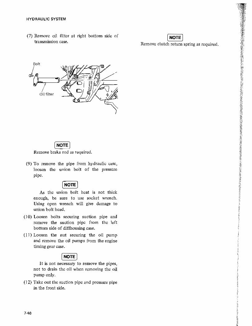
HYDRAULIC SYSTEM
(7) Remove oil filter at right bottom side of transmission case.
Bolt
J~~ Oil filter
[NOTE] Remove brake rod as required.
(9) To remove the pipe from hydraulic case, loosen the union bolt of the pressure pipe.
[NOTE) As the union bolt heat is not thick
enough, be sure to use socket wrench. Using open wrench will give damage to union bolt head.
(10) Loosen bolts securing suction pipe and remove the suction pipe from the left bottom side of diffhousing case.
(11) Loosen the nut securing the oil pump and remove the oil pumps from the engine timing gear case.
[NOTE] It is not necessary to remove the pipes,
not to drain the oil when removing the oil pump only.
(12) Take out the suction pipe and pressure pipe in the front side.
7-46
[NOTE] Remove clutch return spring as required.

HYDRAULIC SYSTEM
Union bolt
Suction pipe
Oil filter
Oil pump
Hydraulic piping of MT180H/HD
Union bolt
Suction pipe
/~-~- HST inlet pipe
O~Oil filter
Pressure pipe ~~~ <':,
~ t> '1;lj ~\)
Oil pump
7-47

HYDRAULIC SYSTEM
Installing the pipings and pump
[NOTE] Be sure to replace "0" rings with new
ones. When assembling, apply clean oil and assemble carefully.
The procedure of re-installing the pipings and pump is reverse of the foregoing removal pro. cedure.
Item Tightening torque
Pup Suction pipe 1.0 "" 1.2 kg-m
Pump side (7.2 ~ 8.7 ft-lb)
Pressure pipe 1.0 ~ 1.2 kg-m ( 7.2 ~ 8.7 ft-lb)
Transmission Suction pipe 2.5 ~ 3.0 kg-m case side (18.1 ~21.7 ft-lb)
Hydraulic Union bolt 4.5 ~ 5.5 kg-m case (3 2.5 ~39.8 ft-lb)
Oil Filter Bolt 2.5 ~ 3.0 kg-m
(18.1 ~21.7 ft-lb)
7-48

HYDRAULIC SYSTEM
OIL PUMP
Construction This oil pump [Nachi-GP-3607A] is of the
gear type, employing the pressure loading system. The pressurized oil is forced out to the rear side of bearing bushing, and the minimum clearance is maintained between the gear teeth and bushing to minimize internal leakage, thereby securing a high volumetric efficiency even at high-pressure-Iow-speed operation. (The bearing bushing serves as a pressure loading component and casing at the same time.) The bearing bushing is of movable design, and, as a result, it is able to maintain a proper clearance whether the bushing swells due to heat or is worn due to protracted low-temperature operation.
The bearing bushing is designed to be lubri cated by low pressure oil which' is forced fed, independently of the pressurized oil on the outlet side. This prevents the seizing-up of the bearing and the damage of the oil seal.
As far as the oil is clean, 90 percent of the specified volumetric efficiency can be secured for a long period. The pump has been tested for 4000 hours continuous operation and proven to maintain high-performance.
o IF==I Outlet
(NOTE) a) The pump oil seal is made of synthetic
resin, and therefore, mineral oil should be used for lubrication. Use of acid and alkaline oil, kerosene, and high octane vegetable oil is not allowed. Extremely high temperature oil may cause corrosion to the oil seal.
b) The oil should be gear oil SAE 80. For details, refer to the Instruction Book.
Removal
Hydraulic oil (transmission oil) need not be drained out for this removal.
( 1) Open the bonnet.
(2) Remove safety cover on the left.
(3) Loosen bolts securing pressure and suction
pipe connections. Recover "0" rings.
(4) Loosen nuts securing the pump to timing gear case, and take out thepump.
7-49
-

HYDRAULIC SYSTEM
Disassembly
[NOTE] The oil pump should be disassembled
iR a clean place, and the tools must be also clean. All disassembled parts are blown with compressed air for drying, after being washed. Do not use rags.
Take care not to damage the body and cover, because they are made of aluminum alloys.
For this disassembly work, refer to the
exploded view.
(1) Loosen the bolt (L) with a hexagon hole, and remove the cover (J) and "0" ring (I).
(2) Push the drive gear (D) into the body (A), and the bushing (F) can easily be taken out by finger. Remove the bushing (F), and remove the drive gear (D) and driven gear (E). The bushing (C) can be take out together with the "0" ring (B).
F
J G /
I ~ 0
~\ C) H I
I
Inspection
Replacement of worn or damaged parts should be done with special care. In order to increase pumping efficiency, the gear rotates with its teeth in slight contact with the pump casing. The contact is evidenced on the low pressure side of the pump. After a long period of use, the oil will become dirty, and bushing holes and journal bearings will be worn. As a result, the
7-50
The disassembled parts should be arranged in order. As for the shafts and bushings, their positions should be correctly memorized.
When installing bushings, take care not to confuse the bushing (C) for bushing (F) in relation to their positions.
Each bushing has a mark A or C stamped on its end. A bushing having mark A shouW be installed on the cover side. (e.g. A indicates clockwise rotation, and C denotes counterclockwise rotation.) The oil seal (M) should not be removed unless otherwise broken. When pulling ou t the oil seal (M) from the body, take special care not to scratch the housing bore.
A-Body B-"O" ring C-Bushing "A" D-Drive gear E-Driven gear P-Bushing "C"
M
I ~
G "0" ring Ii "0" ring I -"0" ring J.-Cover K -Washer L -Bolt M-Oil seal
casing wall begins to show wear. If the amount of wear exceeds 0.05 mm (0.002 in.), the clearance between the gear teeth and the casing wall will be excessive, and oil leakage will increase. This will reduce the performance of the pump. Replacing the bushing will not be effective to improve the performance. The use of a Worn bushing is not recommended except when the pump is operated under low pressure and with special care.

In general, working parts are subject to wear after a long period of use, and there will be not a big difference in wear between them. It is advisable, therefore, that when any component parts show an excessive wear, the pump itself should be replaced, instead of replacing worn parts. It will be more economical.
Each part should be washed with kerosene and blown with compressed air. All removed "0" rings should also be replaced. Check the gears and gear shafts for scratches and broken teeth. The contact ratio in a pair of gears in mesh should be even. Measure the shaft diameter with an outside micrometer calipers. If the measurement shows a smaller value than Nachi -13.96 mm (0.550 in.) ,replace the shaft.
Check the bushings for deformed bore and scratches. If any discoloring of a gear can be considered to be related with a defective bushing, check for the relief valve and related oil passages. If the length of a bushing is shorter than the value as shown below, it should be replaced.
I 16.80 mm (0.661 in.) I
Any discolored gear should also be replaced. Measure the clearance between the shaft and bushing. If the measurement is larger than the following value, the bushing should be replaced.
I 0.177 mm (0.006 in.) I Reassembly
Make sure that all parts are clean. If the oil seal (M) has been removed, it should be replaced. To install the oil seal, use a press. (The seal lip must face inward.)
(I) Place the "0" ring (B) on the bushing (C), and coat it with good quality of mineral grease. Insert it in the body (A) and push it in further. A pair of bushings must be true and coat it with good quality of oil. Insert it in the body (A) and push it in further. A pair of bushings must be true fitted in place without requiring force. If the bushing has a scratch on its surface, it
HYDRAULIC SYSTEM
will not move smoothly. In this case, pull out the bushing and smooth down the raised part with oil stone. Make sure that the surface of the bushing is smooth. For this check, use a surface plate. After using oil stone, be sure to wash the bushing. Oiling the bore will make it easy to install the bushing. Make sure that, after installation, the "0" rings are in place.
The "0" ring must be located between the bushing and the bottom of body. The leading gear type is greatly affected by the result of reassembly. Make sure that the escape groove in the bushing surface is not inclined. Incorrect reassem bly will not provide the pressure balance effect, and as a result, the bushing in the bore will be deformed by pressure.
(2) When inserting the drive gear (D) into the body (A), take care not to damage the oil seal with the stepped (machined) part of the gear shaft. Insert the drive gear (D) and the driven gear (E) into the body (A).
(3) Fully grease the bushings (F) in pair, and insert them in the body. Place the "0" rings (H) on the bushing (F).
(4) Place the "0" rings (G) and (I) on the cover, and place the cover, Finally tighten the bolt (L) with a hole by using a hexagon wrench. Tightening torque is 0.8 kg-m (5.77 ft-Ib). Lock the bolt head with center punch and feed a small quantity of oil through the port.
(5) Make sure that the reassembly is done perfectly by turning the drive gear (D) with an open end wrench. If the gear turns smoothly, the assembly is correct. If too tight, correct it.
7·51

HYDRAULIC SYSTEM
Installation
(1) Align the pump shaft with the pump drive shaft, and install it to the engine timing gear case.
(2) Set the "0" ring correctly, and install the suction pipe and delivery pipe to the pump.
T.est Special care should be taken for test run ,
particularly when bushings, gears and body have been replaced. Test run should be continued at least for 30 minutes. First, make sure that the engine oil, cooling water, transmission oil and other components of the tractor are all perfect. Run the engine with no-load at idling speed, and when oil temperature rises as specified (engine water 82° C or 180° F), increase the engine speed to increase the pump delivery. Operate the control lever for hydraulic control, and give load to the pump.
7·52
In particular, while operating the pump, check the temperature of the pump. If the temperature is excessively high (about 80°C or 176°F), reduce the engine speed temporarily, and continue no-load operation until working parts are fully run in.
(NOTE) The disassembly and reassembly of
the pump are relatively easy, but it should not be unnecessarily disassembled because of trouble of the hydraulic system, of which causes are unknown. Avoid performing disassembly for repair in the field, because it is very difficult to prevent dust and dirt from entering the pump. Parts may also be scratched.

HYDRAULIC SYSTEM
ADJUSTMENT
Adjusting the control valve fork
It is required to adjust the fork so as to position it correctly because hole diameter is bigger than that of the tip of spool valve.
Make valve link vertical by means of position control lever. Loosen nut at the tip of spool
Control valve
~
valve, and adjust fork by moving up and down so that both upper part of the link pin and lower part of valve link set pin come to 12.0 +&.5 mm (0.47 +g.Q2 in.). After adjusting it to the prescribed dimension, tighten nut, secure the fork and lock it with lock plate.
Valve shifter
Valve link
Feed back shifter
120+0.5 . 0 mm
(0.47 +g.02 in.)
Adjusting the flow control grip
Flow control grip
(1) Attach implement to 3-point linkage and place position control lever in lower position.
(2) Start engine, lift up implement and stop the engine.
(3) Loosen nut on the tip of flow control grip.
(4) Turn the position control lever to LOWER position, and make sure the implement is held.
7-53
I
I
II' l~

HYDRAULIC SYSTEM
[NOTE) In case the implement is apt to be
lowered, tum the adjusting screw more clockwise. Start the engine again, tum the control lever to RAISE position. Then tum the control lever to RAISE position, stop the engine and lower the control lever to make sure that the implement is held to the full.
(5) Tum the pilot screw slowly counterclockwise and move it to the position where the implement starts to be lowered. Turn the pilot screw clockwise to the position where the implement is stopped.
Lock the flow control grip with nut.
(6) Start the engine again and turn the control lever to RAISE position. Then make sure that the implement is stopped at the position where the flow control grip is turned clockwise while the implement is lowered rapidly by turning the stopper lever counterclockwise.
End play to be 5 to 15 mm (0.2 to 0.6 in.)
Flow control grip
Setting of flow control grip
Adjusting the position control
(1) Remove the lift rod from lift arm.
(2) Start engine and locate the control lever at RAISE position.
(3) In case the end play is more than 5 to 15 mm (0.2 to 0.6 in.) on the lift arm.
Loosen lock nut of the feed back rod and extend the feed back rod by turning the rod counterclockwise.
Position control feed back rod
;~"I . ",-.L ..
7·54

(4) In case there is no play on the tip of lift arm and relief valve is worked.
Loosen lock nut of the position control feed back rod. Then screw the feed back rod into the lift arm side and adjust it so as to obtain the prescribed end play.
HYDRAULIC SYSTEM
7-55

HYDRAULIC SYSTEM
TROUBLESHOOTING
Trouble Possible cause Remedy
Implement does not move a) Weight of the implement exceeds Check the weight of the implement up even when the control lifting capacity lever is set to the lifting b) Gear pump discharges no oil Replace the gear pump positions. (damaged drive shaft)
c) Air is mixed in the pipe line Bleed air from the pipe line Refer to the items, "Oil ftlter" and "Notes," bleed air from the pipe line.
d) Shortage of hydraulic oil Check the level of hydraulic oil and supply if not sufficient
e) Clogged oil ftlter element Clean the oil ftlter element
f) Dropped set pressure of the pump Readjust the relief pressure: relief 135 +g kg/cm2 (1920 +7 5 psi) or replace
with new one
g) Unloader valve or poppet does not Disassemble and clean the unload valve close and correct flaw. Then, confirm smooth
operation of the unload valve.
h) Defective assembly of control valve Adjust properly
The implement set in a) Flaw or dust on the poppet and seat Correct, clean or replace neutral shows hunting surface while the engine is b) Flaw or dust on the check valve Correct, clean or replace running. * and seat surface
c) Flaw or defect on the "0" ring Check and replace the "0" ring if defective
d) Oil leakage from the piston and Check for the cause and repair defective cylinder parts
e) Oil leakage from passage between Check the "0" ring and replace if control valve and cylinder defective
f) Hydraulic oil Replace with proper hydraulic oil
Lifting speed of the a) Flaw or dust on the unloader valve Clean or replace implement is found seat surface Replace the unloader valve or the body. slower than the standard.
When replacing the body; replace the spool valve at the same time.
b) Oil leakage due to flaw on the Correct or replace the relief valve relief seat surface poppet
c) Leakage inside the cylinder Check, correct or replace the cylinder and piston
Check the "0" ring
7-56

Trouble Possible cause
The implement set in a) Inferior power volumetric efficiency neutral shows hunting of the pump while the engine is b) Clogged strainer running.
Defective operation of a) Dust between the body and spool the control lever b) Sticking in the spool valve
c) Sticking in the link system
Temperature of hydraulic a) Relief valve is operating always oil is too high
b) Lower pump volumetric efficiency
c) Flaw on the unloader valve, body and seat surface
d) Oil leakage due to flaws on the relief valve seat surface
e) Oil leakage from the cylinder or piston
f) Sticking in the pump
Abnormal sound a) Sticking in the pump
b) Insufficient suction of the pump
c) Air is sucked in.
d) Air suction from the pump oil seal
e) Improper hydraulic oil in use
HYDRAULIC SYSTEM
Remedy
Replace the pump (Check for the oil leakage )
Wash the oil filter
Check the oil for contamination
Replace the oil if contaminated
Remove and clean the valve
Correct or replace the spool.valve
Replace the spool valve and body at the same time.
Disassemble and correct the defective part
Replace if correction is impossible
Readjust the relief valve
Readjust the link system
Check and adjust the weight of the imple-ment
Check and correct improper assembling and the control valve.
Check the oil for contamination
Replace the pump
Check the oil for contamination
Replace the body and unloader valve
Replace the body and spool valve as a set
Check the oil for contamination
Correct or replace the relief valve
Check and correct the defective parts
Replace the pump
Replace the pump
Clean the oil filter element
Check the oil for contamination
Check "0" rings of each joint for tightening
Bleed air from pipe line
Refer to the items, "Oil filter" and "Notes," bleed air from the pipe line.
Check, correct or replace
Replace with proper one
7-57 i j

HYDRAULIC SYSTEM
Trouble Possible cause Remedy
Implement lowers naturally Follow the steps described in the * marked item, which has the same cause. when the engine stops
Implement lowers natl.lrally a) Control lever moves toward lowering Use a stronger friction spring to prevent the while traveling direction during mnning control lever from moving
b) Insufficient set pressure of cylinder Adjust the pressure to be as specified relief valve
Pump
Trouble Possible cause Remedy
Oil leakage a) Damage of shaft oil seal Replace with new one
b) Damage of gasket Replace with new one
Noise Cavitation a) Clogged strainer Clean the strainer
b) Low oil temperature Raise the temperature
c) Unsuitable oil Replace with a proper one
Air is mixed d) Insufficient oil Supply oil up to the specified level
e) Air entered from the suction side Repair the defective parts pipe line or joint
f) Damage of the shaft oil seal Replace with new one
Discharge amount is a) Damage of the bearing gear and Replace the hydraulic oil and clean the oil decreased and discharge body due to foreign matters mixed strainer and pipe line pressure is not increased b) Damage of the bearing gear and Replace the bearing gear and body or re-
body due to exhaustion of oil place the working oil and clean the oil strainer and pipe line.
c) Insufficient oil Supply oil up to the specified level
d) Damage of bearing, gear and body Adjust the pressure of the pump relief valve due to overload as specified
e) Damage of halfeight gasket Replace with new one
7-58

HYDRAULIC SYSTEM
SPECIFICATIONS
~ Specification MT180/D I MT180H/HD
Type of cylinder Single action cylinder
Diameter of piston 60 mm (2.36 in.)
Stroke of piston 71 mm (2.80 in.)
Maximu!)ll~t power at the end of lower n 500 kg (1103 lb)
Pressure for pump relief valve setting 135 kg/cm2 (1920 psi)
Type of h~draulic pump Pressure loading gear type
Model of hydraulic pump Nachi: GP-3607 A
Output of hydraulic pump (at' 2700 engine rpm)
12.9 liter/min (3.4 GPM)
Con trol valve type 2 spool valve with unload valve
Oil lock valve In-line non return valve automatic flow control valve
Strainer mesh #42 x 100 mesh
Hydraulic oil Gear oil SAE #80
Oil capacity 18 liters (4.74 U.S. gallon) [same as transmission oil]
Control Position control, flow control and lift lock
External service PT3/8 tap
Hydraulic adaptor plate Optional
7-59


CHAPTER 8
ELECTRICAL SYSTEM
ISO


TABLE OF CONTENTS Page
Description .... . . . . . . . . . . . . . . . . . . . . . . . . . . . . . . . . . . . . . . . . . . .. 8-1
Wiring diagram. . . . . . . . . . . . . . . . . . . . . . . . . . . . . . . . . . . . . . . . . . . . .. 8-3
Battery .................................................. 8-5
Handling the perfector type battery
Charging the battery ...................................... 8-5
8-5 Precautions for charging .................................... 8-6
Care of the battery ........................................ 8-6
Safe battery handling ...................................... 8-8
Emergency starting (Use of booster battery and jumper cables) ...... 8-8
Battery diagnosis . . . . . . . . . . . . . . . . . . . . . . . . . . . . . . . . . . . . . . . . .. 8-9 Safety starter switch ........................... , ........... . 8-11
How it works ............................................ 8-11
Adjustment . . . . . . . . . . . . . . . . . . . . . . . . . . . . . . . . . . . . . . . . . . . . .. 8-11
Fuse .................................................... 8-11
Starter. . . . . . . . . . . . . . . . . . . . . . . . . . . . . . . . . . . . . . . . . . . . . . . . . . .. 8-12
Construction ............................................ 8-12
Testing the starter on the tractor ............................ " 8-13
Removal ................................................. 8-13
Testing a removed starter. . . . . . . . . . . . . . . . . . . . . . . . . . . . . . . . . . .. 8-13
Inspection .............................................. 8-14
Installation .............................................. 8-16
Alternator ................................................ 8-17
Construction ............................................ 8-17
Removal ................................................ 8-18
Testing and adjustment .................................... 8-18
Installation .............................................. 8-20
Regulator. . . . . . . . . . . . . . . . . . . . . . . . . . . . . . . . . . . . . . . . . . . . . . . . .. 8-21
How it works ............................................ 8-21
Testing and adjustment .................................... 8-21
Glow plugs and glow plug indicator. . . . . . . . . . . . . . . . . . . . . . . . . . . . .. 8-23
How they work ............................................ 8-23
Testing .................................................. 8-23
Solenoid switch ........................................... 8-24
Engine stop system ......................................... 8-25
Testing procedures ......................................... 8-27
Specifications ............................................... 8-29

:;~ "j{
,J
o

ELECTRICAL SYSTEM
DESCRIPTION
The electrical system of the MITSUBISHI MT160/D, MT180/D and MT180H/HD operates on 12 volts and consists of an alternator, voltage regulator, starter, glow plugs, headlamps, pilot lamps, switches and a l2-volt battery. Its ground polarity is negative (-).
Generator and voltage regulator
The generator supplies current to keep the battery in charge state, replacing the energy consumed by the starter motor and lamps. The generator charging rate is controlled by a voltage regulator which controls the generator output, thereby maintaining a charging rate, and prevents the battery from overcharging under varying temperatures and operating conditions.
Starter switch and starter circuit
The starter switch is actually a "heat and start switch" and permits current to flow from the battery to the glow plugs in its "H" position and to the starter in "S" position. The starter circuit is equipped with a safety starter switch which is mounted on the sub shift mechanism. This switch closes only when the sub shift lever is in neutral position to permit the current to flow to the starter. This is for preventing the tractor from jerking accidentally when the engine is started.
Glow plugs
Three sheathed type glow plugs, one for the combustion chamber of each cylinder, are used. The glow plug indicator mounted on instrument panel glows red when the plugs are energized.
Pilot lamps
The water temperature pilot lamp, engine oil pressure pilot lamp and battery charge pilot lamp are clustered in one and mounted on the instrument panel. These pilot lamps are connected to their respective sensing switches.
"Polymion" battery (perfector type)
Manufactured and sold under the trade name of "Polymion" battery by JAPAN STORAGE BATTERY CO., LTD., this 12-volt, 45-amperehour perfector type battery Model NXIOO-S6L (S) is standard on MTI60/D, MTI80/D and MTI80H/HD. This battery features its extra thin separators which are in base material polyolefin; they are homogeneously porous to permit electrolyte to freely circulate between cell plates. The "Polymion" battery, because of such separators, gains an advantage over an ordinary battery in capacity per size. In other words, this battery is capable of far more power than an ordinary battery of like size. Thus, it is not advisable to substitute this battery with any other type of ba ttelY of like size.
Following are the standard items of electrical equipment mounted on MTI60/D, MTI80/D and MTI80H/HD:
Battery ......................... .
Starter motor .................... . Alternator ...................... . Indicator lamps .................. .
Water temperature pilot lamp switch Engine oil pressure pilot lamp switch
NX 1 00-S6L(S) 12 volts, 45 ampere-hours MITSUBISHI M002T50371, l.6 kilowatts, 12 volts MITSUBISHI AH2053M4, 12 volts, 35 amperes Water temperature pilot lamp, engine oil pressure pilot lamp, battery charge pilot lamp
Glow plugs. . . . . . . . . . . . . . . . . . . . . .. Sheathed type, 10.5 volts, amperes Glow plug indicator ............... . Voltage regulator ................. .
OCT - 1979
Red-heat type, 30 amperes MITSUBISHI RQB2220D 1
8-1

ELECTRICAL SYSTEM
Engine ON-OFF key switch Lighting switch Safety starter switch Headlamps ...................... . . Two flashing lamps with turn signal . Tail lamp . Horn Fuse holder' ..................... .
Stanley 12 volts, 25 watts/25 watts
Box type with 4 pieces of lOA cartridge type fuse
Following are the optional items of electrical equipment:
Working lamp
8-2
~:2
J,

TEM?I
l--'- '--
co W
E::U ... ~~ .. ~~
Warning lamp Assy. 123.4W
I
i Check botton
01lSR/W
II 2B/W
0.5\'11
l{j
Flusher lamp (R) Timer unit MlD 12V 32CP (26.8W)
Flusher lamp (L) WL _____ --l=:]]!zI:~;j~=t·MlO 12V 32CP(26.8W)
0.856
~~~~~ii~~et~r~ntte:m1~~.1 switch,
~ Fuse lOA I 2BIY i"2BfY----"'1
I @~9 ~~-~====:;r;-;-;-;-;-;-;;t-=-;;-;-~~~6ytB5~B-!;-~:~O~~: ! \;/;I O.SSR 085R 085R Ir~R I
r II I
Fuel lamp Horn I lL.-------.J 12V 3.4W Tractor meter 12V 1.5A L---Front-p~T.o:--- __ ---.JFront P.T.D, switch
123.4W
O.BSl O.85L
osa O.SG(W
Work lamp 1230W
Tail lamp 128W
~ -Solenoid Q,5B/G
OH pressure switch
Temp. switch
Connection mark
---@: LA --eo: CA --l- :TAB
--<D: LE --a: CB ----£J :CS
~ r---, Inside L __ :'J w/option
~ Male
B : Black L : Blue G : Green R : Red W: White Y : Yellow
:E IIIBCI
" IIIBCI
2 a
" IIIBCI
> a
= a:
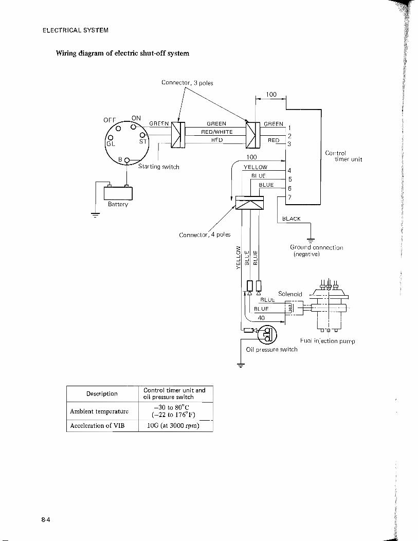
ELECTRICAL SYSTEM
Wiring diagram of electric shut-off system
Connector, 3 poles
GREEN
RED!WHITE
RED
Starting switch
Battery
Connector,4 poles
Description Control timer unit and oil pressure switch
Ambient temperature -30 to 80°C
(-22 to 176°F)
Acceleration of VIB lOG (at 3000 rpm)
8-4
100
100
GREEN
1-----12 I--_R_E..::.D--j 3
,y_E-'L""L""O-'-W-'----_--t 4
"=-=-=-=---1 5 i-----I6
7
BLACK
Control timer unit
Ground connection (negative)
~SOI""_O} ~!~ : I r-· - -'--___ -+.....J
l-~j Fuel injection pump
Oil pressure switch
ELECTRICAL SYSTEM
BATTERY
HANDLING THE PERFECTOR TYPE BATTERY
This battery is of a perfector type and as long as plugs are properly sealed, the battery will operate considerably long. For caution's sake, however, give it an initial charging before use. As the initial charging to this battery, a quick charging is allowable unless the specific gravity of its electrolyte is considerably dropped. In freezing weather, warm up electrolyte before pouring it into the battery.
Following are the basic rules to be followed in handling this battery:
(1) Take sealing tapes off filler plugs and remove the plugs.
(2) About 2.8 liters (3 quarts) of electrolyte will be required to fill the battery up to level. The specific gravity should be 1.260 as corrected to 20° C (68° F).
(3) When filling the battery with electrolyte, make sure that the electrolyte temperature is not higher than 30° C (86°F).
(4) After filling the battery, leave it for a while un til the electrolyte level goes down; then, replenish it to the upper level.
(5) The battery will self-discharge if it is kept out of service for long periods of time, or if cell plates are left exposed to the air due to poorly seale,d plugs. Such a battery will not deliver the amount of current enough to cause the starter to crank the engine properly even if it is filled with electrolyte up to the upper level. In such a case,
remove the battery from the tractor and recharge it.
(6) Where the tractor is stored with its battery filled with electrolyte up to level, check the specific gravity of electrolyte and recharge the battery when the specific gravity is below the specified value.
[NOTE] For measuring the specific gravity, be
sure to confirm the gravity value obtained in filling in electrolyte for the first time.
(7) If the specific gravity of electrolyte is found below 1.200, charge the battery slowly at the current of 5.0 amperes. Never make a quick charging.
CHARGING THE BATTERY
Slow charging
To recharge the battery which has been left out of service over long periods of time:
(I) The charging current should not exceed 1/20 of the battery capacity; it is normally 2 to 2.5 amperes.
(2) The length of time required for charging is 10 to 20 hours.
Regular charging
To recharge the battery which is discharged in normal service:
(1) The charging current should not exceed 1/10 of the battery capacity; it is normally 4 to 4.5 amperes.
(2) The length of time required for charging is 1.2 to 1.5 times of the value obtained by dividing the rate of discharge (ampere-hour) (presumed) by the charging current.
8-5

ElECTR ICAl SYSTEM
Quick charging To charge the battery by using a quick charger.:
(1) The charging current should not exceed the battery capacity.
(2) The length of time required for charging is
30 to 60 minutes.
The charging should be continued until the battery is gassing freely and there is no rise in the specific gravity of electrolyte. In fully charged battery, a charging voltage of higher than 15 volts will be noted at each cell and a
specific gravity of 1.260 as corrected to 20° C (68 ° F) will be read.
PRECAUTIONS FOR CHARGING
When recharging the battery (removed from the tractor), obs.;rve the following rules:
(1) A battery that is being charged gives off highly explosive gases. Never light a match or a cigarette near such a battery.
(2) If battery temperature rises above 45°C (113° F) during charging, stop charging and have a wait for a while to permit the battelY to cool down, or reduce the charg
ing current to 1/2:
(3) In cold weather, a rapid voltage rise will occur in a battery being charged, resulting in an undercharged battery. In such a weather, charge a battery in a warm place.
(4) Remove the battery from the tractor, and remove vent plugs (if equipped) to improve
ven tila tion.
(5) When connecting or disconnecting the leads from a charger to the battery, turn off the switch on the charger, making sure that no charging current is flowing into the battery.
(6) To charge the battery on the tractor with an external charger, be sure to take off the grounded-terminal cable clamp and make good connection of the charger with the battery by clamping the positive (+) lead of the charger on the positive (+) terminal
8-6
of the battery and the negative (-) lead on the negative (-) terminal.
(7) Never use a battery tester on a battery that is being charged. This will allow sparks,
resulting in accident.
CARE OF THE BATTERY
Checking the specific gravity of electrolyte
(1) As the. battery discharges, the electrolyte gradually loses its specific gravity. Check the specific gravity to determine the state of charge of the battery.
(2) To check the specific gravity, use a battery hydrometer, and take the reading at eye
level.
-" Eye level
Electrolyte
--->0 Float
How to read hydrometer
(3) The specific gravity varies with temperature. This effect is due to the fact that as a liquid cools it becomes thicker and .gain gravity. As a liquid warms it becomes thinner and loses gravity. The same is true of electrolyte. Thus, temperature should be considered when a gravity reading is taken. Make a correction. if the electrolyte temperature is above or below 20°C (68°F)
standard.

ELECTRICAL SYSTEM
Conversion table of specific gravity of electrolyte
Sulfuric O°C 5°C 10°C 25°C 30°C 35°C 40°C 45°C Temperature acid (32°F) (41°F) (50°F) (noF) (86°F) (95°F) (104°F) (113°F) coefficient
weight %
28.0 1.218 1.215 1.212 1.202 1.198 1.195 1.191 1.188 28.5 1.223 1.220 1.217 1.207 1.203 1.200 1.196 1.193 0.00067 29.1 1.228 1.225 1.222 1.212 1.208 1.205 1.201 1.198
29.8 1.233 1.230 1.227 1.217 1.213 1.210 1.206 1.203 30.4 1.238 1.235 1.232 1.222 1.218 1.215 1.211 1.208 31.0 1.244 1.241 1.237 1.226 1.223 1.219 1.216 1.212 0.00070 31.6 1.249 1.246 1.242 1.231 1.228 1.224 1.221 1.217 32.2 1.254 1.251 1.247 1.236 1.233 1.229 1.226 1.222
32.8 1.259 1.256 1.252 1.241 1.238 1.234 1.231 1.227 33.4 1.264 1.261 1.257 1.246 1.243 1.239 1.236 1.232 34.0 1.269 1.266 1.262 1.251 1.248 1.244 1.240 1.237 0.00071 34.6 1.274 1.271 1.267 1.256 1.253 1.249 1.245 1.242 35.2 1.279 1.276 1.272 1.261 1.258 1.254 1.250 1.247
35.8 1.284 1.281 1.277 1.266 1.263 1.259 1.255 1.252 36.4 1.289 1.286 1.282 1.271 1.268 1.264 1.260 1.257 37.0 1.294 1.291 1.287 1.276 1.273 1.269 1.265 1.261 0.00072 37.5 1.299 1.296 1.292 1.281 1 .. 278 1.274 1.270 1.266 38.1 1.304 1.301 1.297 1.286 1.283 1.284 1.275 1.271
38.7 1.309 1.306 1.302 1.291 1.288 1.286 1.280 1.276 39.3 1.314 1.311 1.307 1.296 1.293 1.289 1.285 1.281
Conversion formula
Specific gravity _ Hydrometer + Temperature X temperature _ 20°C (
Electrolyte )
at 20°C (68°F) - reading coefficient CC)
(4) Electrolyte (dilute sulfuric acid) specific gravity varies in relation to the discharge. Accordingly the rem&ining level of the battery is obtained by measuring the specific gravity. ~ 1280 ~------------, u °0 1260
~ 1240 +-' :?: 1220 o ~ 1200
'* 1180 '+-o 1160 >-
.5: 1140 <0
5, 1120 u :E 1100 u ~ 1080
(J)
1060L-~~-ll~~L-~~-L~~
100 90 80 70 60 50 40 30 20 10 0 State of charge (%)
It is required to adjust the electrolyte specific gravity of the battery to be 1.260 ±0.01 (20°C = 68° F).
Checking the electrolyte level
The battery case is made of transparent synthetic resin. The electrolyte level can be checked at a glance.
j
ELECTRICAL SYSTEM
Other services
(I) Apply vaseline or grease to terminal posts.
(2) Always keep the top of the battery clean and dry. After refilling, tighten the plugs good and hard and wipe off spilled electrolyte. Once in a while, check to make sure that the cables are clean and tightly clamped to the terminals.
SAFE BATTERY HANDLING
(1) Battery electrolyte, sulfuric acid, is very corrosive and can destroy most things it
touches.
• Be careful not to drip electrolyte on the tractor or on yourself; it will ruin the paint on the tractor or eat holes in your clothes.
• If you get electrolyte on your skin, flush it· off at once with water. Continue to flush for at least 5 minutes. Put baking soda (if available) on the skin. This will neutralize the acid. If such a soda is not available, wash with soap and water.
• If you get electrolyte in your eyes, flush your eyes out with water, over and over again. Get to a doctor at once! Do not wait!
• A battery is unknown to children. Keep children away from a battery that is being charged. Store the battery out of their reach. There was a child who sucked electrolyte through a straw. This could happen again.
(2) Do not check the state of charge by placing a metal object across the terminals.
8-8
EMERGENCY STARTING (Use of booster battery and jumper cables)
In emergency starting, particular care should be used when connecting a booster battery in order to prevent sparks. Following are the rules to be followed in jump starting:
(I) Shut down the engine.
(2) Connect the ends of RED jumper cable to the positive (+) terminal of each battery.
(3) Connect one end of BLACK jumper cable to the negative (-) terminal of the "good" battery. Then connect the other end of the cable to the engine block on the tractor being started (not to the negative (-) terminal of battery) as apart from the battery as possible.
(4) Start the engine of the tractor being started.
(5) Having made sure that the engine is idling, disconnect the cables by following the
reverse of steps 2 and 3 above.

ELECTRICAL SYSTEM
BATTERY DIAGNOSIS
External failures
Failure Possible cause
• Excessively loose or tight hold-down clamps
• Freezing
Cracked case • Oil or gasoline spilled over battery
• Flying stones
• Attacking of chemicals
• Explosion due to clogged vent holes
• Abnormal temperature rise due to excessive charging current
• Excessively tight hold-down clamps Bulged case
• High temperature
• High voltage due to improper regulator setting
• Spilling of electrolyte due to high level Corroded terminals and
• Passage of leak current cable clamps
• Buildup of corrosion around terminals
• Excessive discharge current Burned terminals and
Excessive resistance due to corrosion around terminals clamps •
• Spark due to falling metal objects
Internal failures
Tester Condition Possible cause
• Undercharge due to defective charging system
Electrolyte gravity low in all Overdischarge due to excessive loads
cells •
• Leakage, buildup of corrosion around terminals, or high electrolyte level
Hydrometer Electrolyte gravity low in one or • Impurities in electrolyte
more cells (variation: more than • Separators shorted or continuity between 0,04) cells
• Low electrolyte level
Electrolyte gravity high • Sulfuric acid was added where distilled water should have been poured in
8-9

ELECTR ICAL. SYSTEM
Tester Condition Possible cause
• Overcharge No electrolyte
Electrolyte level low • Hydrometer
Electrolyte gravity is normal, but • Cable clamps loose on terminal posts battery will not deliver current • Terminals and clamps burned
GREEN zone (battelY is normal) • Cable clamps loose on terminal posts
• Battery discharged. Cable clamps loose
Battery tester on terminal posts YELLOW /RED zone
• Battery dead
• Battery has aged
~ 1.220, min 1.220, max
Variation: Battery gravity (variation: (variation:
0.04, min tester 0.04, max) 0.04, max)
Hydrometer O.K. Use without Recharge to cor-GREEN O.K. but recharge rect gravity
Battery tester charging Re-test
Dead? YELLOW/RED Cable clamps loose
Recharge Dead
on terminal posts Re-test Replace
or burned
8-10

ELECTR ICAL SYSTEM
SAFETY STARTER SWITCH
HOW IT WORKS
This switch is, as described previously, a safety means of prevettting the tractor from accidentally jerking when the engine is started. Working as a "circuit breaker" for the circuit between the starter switch and starter motor, this safety switch is governed by the sub shift lever. It keeps the circuit open as long as the lever is being placed to "NEUTRAL" position, even if the starter switch (key) is turned to the start position; it closes the circuit when the switch is turned to the start position with the sub shift lever depressed placed to "High" or "Low" position. Thus, safe engine starting is assured for both operator and tractor.
ADJUSTMENT
Lock nut
Safety starter switch
20±o.5mm(O.79±o.02 in.)
What to be checked and adjusted for this switch is the interval from the plate to the switch end as shown in figure. This interval is specified to be 20 ± O.Smm (0.79 ± 0.02 in.) as measured with the sub shift lever placed to "Neutral" position. If not, adjust it to the specification by means of the lock nuts. Upon complection of adjustment, tighten the lock nuts good and hard, and test to be sure that the starter motor will not rotate when the sub shift lever is being placed to "Low" or-"High" positions even if the starter switch is turned for cranking the engine. And then, make sure that the starter motor will rotate when placing the sub shift lever to "Neutral" position.
FUSE
A IS-ampere fuse is in a cylindrical holder located below the dash panel. When this fuse is blown, replace it with a new one of the specified amperage.
[NOTE] Do not attempt to use a fuse of any
amperage other than is specified (15 amperes).
8-11
I
j

ElECTR ICAl SYSTEM
STARTER
CONSTRUCTION
This starter, because of its built-in reduction gears, is called "internal reduction starter." The motor proper is compact in size and is capable of higher speeds for faster engine cranking.
CD
@@ ®CV ®®
® 1-Magnetic switch 2-Shift lever
3-Front bracket 4-Rear bracket 5-Brush 6-Field coil
7-Armature
8-Pole piece 9-Yoke
1 O-Center bracket 11-Reduction gears 12-0verrunning clutch 13-Front bracket
14-Drive pinion
Starter
Switch
Wiring diagram
Following are the design features of this starter entirely different from those of an ordinary starter:
• In an ordinary starter, drive pinion slides on and along motor (armature) shaft. In this starter, it slides on its shaft separated from the motor shaft.
• Armature rotation or drive is transmitted from motor shaft, through reduction gears, to pinion shaft.
8-12
• Pinion shift mechanism (Bendix drive) is totally enclosed to keep dirt out, lubricating grease in. This design minimizes pinion seizure due to hardened or deteriorated grease.
• Ends of motor shaft are supported by ball bearings (in "antifriction" fashion). This means far less friction to the shaft rotation than in an ordinary starter.
The pinion shift lever, magnetic switch, overrunning clutch and internal circuitry are basically the same as those of an ordinary starter.
The major functional parts of this starter are as follows:
• Motor: The source of drive
• Overrunning clutch: Is operated by shift lever to shift drive pinion into mesh with the flywheel ring gear. After the engine starts, it allows the pinion to spin independently of, or
j
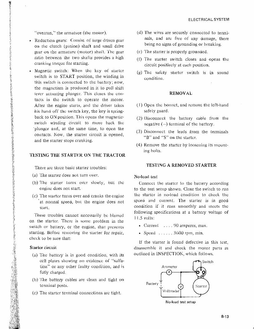
, ~
"overrun," the armature (the motor).
• Reduction gears: Consist of large driven gear on the clutch (pinion) shaft and small drive gear on the armature (motor) shaft. The gear ratio between the two shafts provides a high cranking torque for starting.
• Magnetic switch: When the key of starter switch is to START position, the winding in this switch is connected to the battelY; now, the magnetism is produced in it to pull shift lever actuating plunger. This closes the contacts in the switch to operate the motor. After the engine starts, and the dliver takes his hand off the switch key, the key is springback to ON position. This opens the magneticswitch winding circuit to move back the 'plunger and, at the same time, to open the contacts. Now, the starter circuit is opened, and the starter stops cranking.
TESTING THE STARTER ON THE TRACTOR
There are three basic starter troubles:
(a) The starter does not turn over.
(b) The starter turns over slowly, but the engine does not start.
(c) The s tarter turns over and cranks the engine at normal speed, but the engine does not start.
These troubles cannot necessarily be blamed on the starter. There is some problem in the switch or battery, or the engine, that prevents starting. Before removing the starter for repair, check to be sure that:
Star ter circuit
(a) The battery is in good condition, with its cell plates showing no evidence of "sulfation" or any other faulty condition, and is fully charged.
(b) The battery cables are clean and tight on terminal posts.
(c) The starter terminal connections are tight.
ELECTRICAL SYSTEM
(d) The wires are securely connected to terminals, and are free of any damage, there being no signs of grounding or breaking.
(e) The starter is properly grounded.
(f) The starter switch closes and opens the circuit positively at each position.
(g) The safety starter switch is in sound condition.
REMOVAL
(1) Open the bonnet, and remove the left-hand safety guard.
(2) Disconnect the battery cable from the negative (-) terminal of the battery.
(3) Disconnect the leads from the terminals "E" and "s" on the starter.
(4) Remove the starter by loosening its mounting bolts.
TESTING A REMOVED STARTER
No-load test
Connect the starter to the battery according to the test setup shown. Close the switch to run the starter in no-load condition to check the speed and current. The starter is in good condition if it runs smoothly and meets the following specifications at a battery voltage of 1l.5 volts:
• Current .... 90 amperes, max.
• Speed ...... 3600 rpm, min.
If the starter is found defective in this test, disassemble it and check the motor parts as outlined in INSPECTION, which follows.
No-load test setup
8-13

ELECTRICAL SYSTEM
INSPECTION
Magnetic switch removed from starter
Brushes and brush holders
(1) Check each brush for wear. Replace a brush worn beyond the wear limit line. (See SPECIFICATIONS.)
(2) Check each brush spring for tension with the brush holder installed in place on commutator. Replace a spring weakened or fatigued beyond the service limit.
(3) Check for continuity across positive (+)
side brush holder and holder base. Replace the brush holder assembly if any continuity is noted.
(4) Check each brush holder for installation.
Brush assembly remove from motor
Armature
(1) Test the armature for short circuits on the growler. Also test for ground by placing one test point on the lamination and the other on the commutator. Replace a shorted or grounded armature.
8·,14
Disassembled view of armature
Commutator inspection
(2) Measure the commutator diameter and undercutting of commutator Repair it if the repair limit is reached. The commutator sometimes becomes covered with a film of dirt or gum. This can be cleaned off by polishing with No. 300 to 4,)0 sandpaper.
Field coil
(1) Using a tester, check for continuity across both ends of the coil (brushes). If no continuity is noted, it is an indication that the coil is open-circuited. In such a case, replace the yoke assembly.
(2) Similarly check for continuity across connector and yoke. If continuity is noted, it is an indication that the coil is grounded; check for insulation and, if defective beyond repair, replace the yoke assembly.
(3) Check the pole shoes and coil for installation, making sure that they are installed securely.

Field coil inspection
Magnetic switch
Check for continuity across the terminals "S" and "M" on one hand and across the terminal "S" and body on the other. Any continuity means that the switch is in sound condition.
Overrunning clutch
Check the drive pinion for badly worn or broken teeth. Replace the pinion if damaged.
Disassembled view of overrunning clutch
Reduction gears
Replace the gears if badly worn or damaged.
Front bracket
Check the ball bearing and bushing for wear. Replace the bracket assembly if any of them is badly worn.
Pinion gap
(1) Disconnect connector from terminal "M" on magnetic switch.
(2) Connect the starter to the battery (with the positive (+) cable of the battery connected
ELECTRICAL SYSTEM
to the terminal "S" of magnetic switch and the negative (-) terminal to the starter) to shift the drive pinion out. Under this condition, slightly push the pinion back toward the armature, and measure the gap.
If the gap is out of specification, increase or decrease the number of washers used between magnetic switch and front bracket to adjust it. Increase in the number of washers will decrease the gap, and vice versa.
Overrunning clutch
Pinion gap inspection
[NOTE) a) In this test, never operate the starter
for periods longer than 20 seconds to avoid overheating the switch coiL
b) Too large or too small a pinion gap may also be caused by improperly installed shift lever or defective magnetic switch. Check the lever and switch, too.
Pinion shaft
Check the shaft for thrust gap (axial play). The gap should be less than 5 mm (0.20 in.). If the gap is out of adjustment, put adjusting washer into between the center bracket and reduction gear.
8·15

ELECTRICAL SYSTEM
Washer
Snap ring
Thrust gap-
Center bracket
Thrust gap (axial play) inspection
(l) To put adjusting washer with the pinion off pinion shaft, proceed as follows:
Place reduction gear on pinion shaft. Pass the shaft through center bracket and secure it in place with washer and snap ring. Move the shaft in axial direction to measure the gap. Adjust the gap by pl,ltting the washer.
(2) To put adjusting washer with the pinion on pinion shaft, proceed as follows:
Pass pinion shaft complete with reduction gear through front and center brackets. Tighten bolt and measure the gap by moving the shaft in axial direction. Adjust the gap by putting the washer.
[NOTE] When measuring thrust gap with the
pinion installed, be sure to remove lever spring.
Magnetic switch
(1) Pull-in action
8-16
Apply the battery voltage across the terminals "S" and "M" of the magnetic switch to see if the plunger gets pulled in to shift the pinion; if not, the pull-in coil is open-circuited or the overrunning clutch is defective.
(2) Hold action
With the battery voltage applied across the terminal "S" and the body of the switch, pull out the pinion by hand to the stopper. Release the pinion in this condition to see if the pinion moves back; if not, then the holding coil is in sound condition.
(3) Return action
With the battery voltage applied across the terminal "M" and the body of the switch, pull out the pinion by hand to the stopper. Release the' pinion in this condition to see if. the pinion moves back; if it does move back promptly, then the coil is in sound condition.
[NOTE] In any test outlined above, never
apply battery voltage for periods longer than lO seconds.
INSTALLATION
(a) When installing the starter, clean the mounting flange of starter and the mounting seat on crankcase off oily substance, rust and other foreign matter.
(b) Even a starter which has been tuned up properly will not operate satisfactorily if leads or wires are not of the types or sizes called for, or if connections are poor. Be sure to use leads and wires of the types and sizes called for and tighten terminals good and hard.

ELECTRICAL SYSTEM
ALTERNATOR
CONSTRUCTION
The alternator consists essentially of a threephase generator and a silicon-diode rectifier unit for converting the AC output of the generator into a DC power,
Referring to the longitudinal cross section, rotor assembly (8) is supported by ball bearings (6) (11), bearing (6) being fitted to rear bracket (9) and bearing (11) to front bracket (4)',
CD (j)
CD CD
6-diode rectifier (7) is mounted in a metal bracket called a "heat sink" which takes heat from the diodes during operation,
The rotor shaft carries two slip rings, on which brushes (3) are resting, Excitation current is supplied through the slip rings and brushes to the field coil. Pulley and fan assembly (12) is mounted on the extended portion of the rotor shaft.
@
1-Brush spri ng 2-Brush holder 3-Brush 4-Front bracket
5-Bearing retainer 6-Rear ball bearing 7-Diode rectifier 8-Rotor assembly
9-Rear bracket 1 G··Stator 11-Front ball bearing 12-Pulley and fan assembly
Alternator - Sectional view
8-17
j
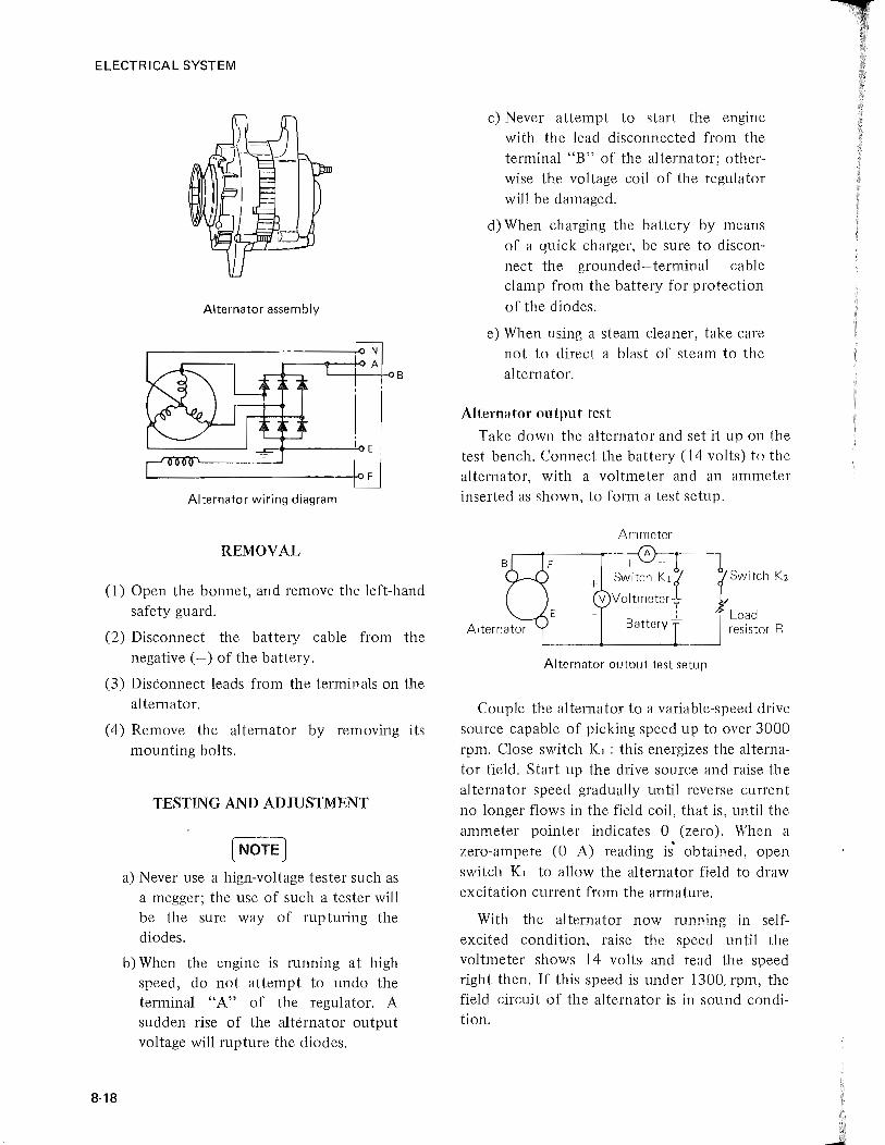
ELECTRICAL SYSTEM
Alternator assembly
L--+--H>B
Alternator wiring diagram
REMOVAL
(1) Open the bonnet, and remove the left-hand safety guard.
(2) Disconnect the battery cable from the negative (-) of the battery.
(3) Disconnect leads from the terminals on the alternator.
(4) Remove the alternator by removing its mounting bolts.
8-18
TESTING AND ADJUSTMENT
[NOrE] a) Never use a hign-voltage tester such as
a megger; the use of such a tester will be the sure way of rupturing the diodes.
b) When the engine is running at high speed, do not attempt to undo the terminal "A" of the regulator. A sudden rise of the alternator output voltage will rupture the diodes.
c) Never attempt to start the engine with the lead disconnected from the terminal "B" of the alternator; otherwise the voltage coil of the regulator will be damaged.
d) When charging the battery by means of a quick charger, be sure to disconnect the grounded-terminal cable clamp from the battery for protection of the diodes.
e) When using a steam cleaner, take care not to direct a blast of steam to the alternator.
Alternntor output test
Take down the alternator and set it up on the test bench. Connect the battery (14 volts) to the alternator, with a voltmeter and an ammeter inserted as shown, to form a test setup.
Ammeter
~-~ + Switch Klt JSWitCh K2
V Voltmeter _ - : Load
Battery - resistor R
Alternator output test setup
Couple the alternator to a variable-speed drive source capable of picking speed up to over 3000 rpm. Close switch K1 : this energizes the alternator field. Start up the drive source and raise the alternator speed gradually until reverse current no longer flows in the field coil, that is, until the ammeter pointer indicates 0 (zero). When a zero-ampere (0 A) reading is' obtained, open switch K1 to allow the alternator field to draw excitation current from the armature.
With the alternator now running in selfexcited condition, raise the speed until the voltmeter shows 14 volts- and read the speed right then. If this speed is under 1300, rpm, the field circuit of the alternator is in sound condition.

Set the load resistance for the highest resistance value (so that little or no load current would flow), and close switches Kl and K2 ; raise the speed gradually while slowly decreasing the setting of the load resistance to increase load current. Under this condition, bring the alternator to a state in which its output voltage (as read on the voltmeter) is 14 volts and the load current is 15 amperes. Read the speed right then; this speed should be under 2500 rpm.
The alternator is in good operating condition when it meets the two requirements stated above: self-exciting speed of 1300 rpm maximum and rated output speed of 2500 rpm maximum. These two are servicing standards.
Bench testing of rectifier diodes
The diodes should be checked for "open" and "short." What is meant by "open" is obvious enough. An "open" diode does not pass any current; its internal circuit is broken somewhere. A "shorted" circuit is that which has its junction ruptured or pierced so that it readily passes current in either direction and' thus does not serve as an electronic check valve.
Of the six diodes, three are on the positive side (connected to output terminal A) of the rectifier and the remaining three on the negative side (connected to ground terminal E). The neutral point of the three windings (star-connected) of the alternator is connected to neutral terminal N.
Diode inspection
ELECTRICAL SYSTEM
(1) Checking for "short"
Use a circuit tester and check the positive-side diodes for continuity in the two directions, normal and reverse, with the tester knob set in the ohmic zone. Put the plus (+) probe pin to terminal A and the minus (-) pin to terminal N: the tester should indicate continuity. Exchange the probe pins, putting positive pin to Nand minus pin to A: the tester should indicate no continuity. The second trial is important; if continuity is noted, it means that one or more of the three positive-side diodes are ruptured. If this happens to be the case, remove the rectifier and check individual diodes.
"Short" inspection
(NOTE) The circuit tester has a built-in battery.
Turning its selector knob to the ohmic (resistance) zone connects the battery to the probe pins, making the positive (+)
pin minus (-) and the negative (-) plus (+).
The three negative-side diodes of the rectifier can be checked similarly for "short." In this case, the probe pins are to be put to terminals Nand E (as if N were terminal A and E were terminal N in the above check).
(2) Checking for "open"
Remove the rectifier and check each
8-19

ELECTRICAL SYSTEM
diode individually. This check can be accomplished by checking it for continuity in normal direction.
Checking the stator coils for condition
Disconnect the three leads of the stator coil from the rectifier and the neutral lead from terminal N. Check each winding for continuity by putting one probe pin to lead wire N and the other pin to each of the three leads.
Next, check the windings for ground by putting one probe pin to the core and the other pin to each of the three leads. There should be no evidence of continuity. If any continuity is noted, replace the stator.
Checking the field coil for condition
When the field coil is at normal temperature 20°C (68°F), it has an ohmic resistance of about 7.9 ohms as checked at the slip rings. Set the selector knob at the lowest range and put the probe pins to the slip rings. If a reading is much less than 7.9 ohms, it is likely that there is a short-circuit between coil turns; a much higher reading means that some part of the field circuit is nearly broken.
Field circuit inspection
8-20
INSTALLATION
[NOTE) When connecting the alternator, regu
lator and battery, be sure to match the polarity signs. A failure to follow this precaution will cause large current to flow from the battery to the alternator, resulting in costly damage to diodes or other parts.
e Install the alternator on the left upper part of the gear case. Put distance piece into between the rear face of gear case and the rear bracket and insert shims so that there is no clearance between the case and bracket. Tighten the bolts on the case temporarily.
• Wrap the drive belt around each pulley and adjust its tension. Secure the alternator' brace and tighten the bolts on the case good and hard.

1 ELECTRICAL SYSTEM
REGULATOR
HOW IT WORKS
The regUlator is of two-element type consisting of a voltage relay and a pilot lamp relay. In the view of the regulator with its cover removed, note that the two relays look alike, each being composed of a coil wound around a core, a spring armature carrying a contact point, a frame for supporting the coil, armature and stationary contact points.
The voltage relay is a means of maintaining the alternator output voltage at constant level regardless of the alternator speed. In operation, it limits the alternator field current as necessary to prevent excess alternator voltage.
The pilot lamp relay has its coil connected ~o the terminal "N" and operates with half the output voltage of the rectifier to merely make or break the pilot lamp circuit. Going out of this lamp signifies that voltage is available from the alternator.
l-White/red lead
IG F L CD(2)Q)
§(~ ~ ~)S @@® A N E
CD (2) Q)
~\ ® 4-White lead
2-White/black lead 5-Yellow lead 3-Yellow/white lead 6-Black lead
Color identification of regulator leads
[NOTE] When the regulator connector is re
placed, adhere to the lead color identification to avoid misconnection.
TESTING AND ADJUSTMENT
[NOTE] a) Do not connect the terminals "F" and
"IG" the wrong way round; otherwise the wire harness or points will be burned.
b) When testing the regulator on the tractor, be sure to turn the starter (key) switch to OFF position and disconnect the lead from terminal "IG" to avoid burning the wire harness and points.
c) Do not break cachet of the regulator. This will release Satoh from any guarantee.
Testing for no-load regulated voltage
Have a voltmeter connected across terminals "A" and "E." Run the engine at idle speed and, while so operating the engine, disconnect the lead from terminal "B" to run the alternator in no load condition. Under this condition, increase the alternator speed up to 4000 rpm and check voltmeter indication. The regUlator is in good condition if the voltage read on the voltmeter is 14 to 15 volts.
Battery charge pilot lamp
Switch
Regulator test setup
8·21 j

ELECTRICAL SYSTEM
Testing for pilot lamp lighting voltage
(1) Connect the pilot lamp and regulator to the battery as shown, with the voltmeter, switch and variable resistor in between,
(2) With the pilot lamp lighted, gradually raise the voltage by changing the setting of the resistor to see if the lamp goes out at anywhere between 4,2 and 5,2 volts,
(3) Gradually lower the voltage to see if the lamp lights up at anywhere between 0,5 and 3,0 volts,
f Variable resistor
I I· G I~_~ 1 ~
Switch Battery
Regulator test setup for checking pilot lamp lighting voltage
Item Standard
Pilot lamp goes out at 4,2 ~ S,2V
Pilot lamp lights up at 0,5 ~ 3,OV
8-22

ELECTRICAL SYSTEM
GLOW PLUGS AND GLOW PLUG INDICATOR
HOW THEY WORK
The glow plugs are of sheathed type and constructed as shown. The glow plug indicator simulates the operation (energization) of the plugs.
Silicone rubber cap
Glow plug
Glow plug indicator
TESTING
• Connect the positive (+) lead of the battery to the terminal of glow plug and the negative (-) lead to the body of the plug. The plug is in good condition if it glows red when it is so connected to the battery.
• The glow plug indicator should glow red within 25 seconds. If it will not glow within 25 seconds, it is an indication that anyone of three glow plugs (within the engine) is shorted.
Glow plug inspection
8-23

ELECTRICAL SYSTEM
SOLENOID SWITCH
(1) Temporarily install the solenoid (1), nut (2) and gasket (3) to the crankcase. (Coat the effective thread portion of the solenoid with sealant, Three-Bond 1212 or 1211.)
(2) Turn in the solenoid so that clearance "C" becomes zero at the injection pump rack position "zero."
(3) Turn back the solenoid 30° to 45°. [The rack to shaft clearance will become 0.15 to 0.20 mm (0.0059 to 0.0079 in.).] Lock
Rubber cap
the solenoid at that position with the nut. [Nut tightening torque: about 5 kg-m (36.2 ft-lb)]
(4) Confirm that MS is reset securely when the shaft is pushed fully.
(5) Finally, install the rubber cap with its arrow mark facing upward. (The water drain hole comes to the bottom of the cap.)
\ ~2....!\-rI-...,..-J.""':;==;=: ==0=.1=5 ~ 0.20 m~ ::= "=;"'-, I ~t (0.0059 ~ 0.007.9 In.)
III ~ ... I I I
III 1- -------1-H--I1t--t -I f~: -i:DLi-~---
l!::--,+.,...::uhi 11'-____ ---' -:- =J:~., I njection pump rack I .
Shaft
Water drain hole
These portions shall be kept completely free from adhesion of sealant.
Prevent intrusion of detergent into solenoid through these portions.
Installing solenoid switch
~( CAUTION]
Be sure to prevent intrusion of detergent into the solenoid terminals and the inside of solenoid (cord and shaft).
8-24

ELECTRICAL SYSTEM
ENGINE STOP SYSTEM
This system uses a solenoid switch which acts, when the engine starting switch key is turned to OFF, on the fuel injection pump control rack to push it to the "non-injection" position to stop the engine.
Combinations of switch positions
Key Oil Electro- Fuel Function switch pressure magnetic injection
State switch solenoid pump of control engine rack
ON ON ON STOP MS reset-ting
START OFF OFF MS Automatic increase of
Start fuel injec-tion quantity for engine start
ON OFF OFF (SS) Nomal operation
ON ON ON STOP Emergency stop caused by an low-ering of oil
Run- pressure ning
OFF OFF ON. STOP Stopping the engine with key switch turn-ed to OFF
Function . (I) MS resetting
When starting the engine, turning the key switch to ON will close a circuit through which current flows to the oil pressure switch. This will cause transistors Tr5 and Tr4 to become conductive, thus allowing. current to flow from terminal B of the key switch to transistors Tr3, Tr2 and Trl. As the solenoid is excited, the control rack of fuel injection pump is placed in the MS reset position.
(2) Automatic increase of fuel injection quantity for engine start
When the engine starting key switch is turned to START, a short-circuit current
will flow to the condenser C I from ST terminal of the switch. Since the timer function is accelerated, the action of the solenoid will be terminated instantaneously and the fuel injection pump control rack will be set to theMS position automatically.
(3) Normal engine operation
After the engine starts, increase of oil pressure will turn the oil pressure switch to OFF, thus opening the oil pressure switch circuit. Transistors Tr5 and Tr4 will become non-conductive (no current flows from the key switch terminal B to the transistors Tr3, Tr2 and Trl), thus preventing the solenoid from acting.
(4) Stopping the engine with key switch turned to OFF
When the key switch is turned to OFF, discharge current of the condenser C2 which has been charged during engine operation will make the transIstors Tr5 and Tr4 conductive. Resulting current flow from terminal B of the key switch to the transistors Tr3, Tr2 and Tr I will excite the solenoid to stop the engine.
(5) Emergency stop caused by an excessive lowering of oil pressure
If oil pressure lowers excessively during engine operation, the oil pressure switch will be turned on to close a circuit through which current flows from terminal B of the key switch to the transistors Tr3, Tr2 and Tr 1. As the result, the solenoid will be excited to stop the engine.
After the engine stopped, all transistors are kept in non-conductive condition and no current flows in the timer circuit.
8-25

ELECTRICAL SYSTEM
8-26
~~----~-R-9-------T--~~~
B
Tr5
D1 R1
RlO
, ,
~---~--J Reference: Tr1 - Tr4
D1 - D3 C1 - C2 R1 - R12
Transistors Diodes Condensers Resistors
Control timer circuit diagram
(3) Duoonnected wiring to terminal ST of key switch
Fawty timer circuit
Dbconnected.wlring to oil prnsurc switch
Docs solenoid act normally when
slopping the engine?
YES
Checking the system for proper operation
(1) Make the wmng of this system in accordance to with the wiring diagram.
(2) Remove the tie-rod cover to give access to the fuel injection pump control rack. Turn the starting switch key to ON and check to see that the solenoid comes into action, causing the control rack to move
accurately to the MS resetting position.
(3) Turn the starting switch key to OFF and reinstall the tie-rod cover. Turn the key from OFF to START, through the ON position, and confirm that the solenoid comes into action at the ON position and the action stops at the START position.
Troubleshooting
If the system becomes malfunctional, find out the cause of trouble using the diagnostic chart below.
Does solenoid act normally when key switch
isptacedinON?
Does a voltage exist
at terminalB?
'Figures in cirde correspond to those on the next item (3).
Oil preuure switch faulty,
YES >--------1 Timer circuit faulty.
NO
NO
NO
Dlsconnected wiring to ON terminal of key switch
Key switch faulty
~~:!I:I6'( ~X~!~ >_N_O ______ -i engine operates?
'>~Y~M~----1r-{~~~~==~ ,. Solenoid faulty. (6)
NO
Timer circuit faulty.
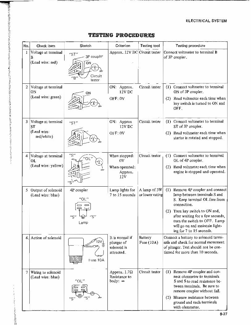
ELECTRICAL SYSTEM
TESTING PROCEDURES
No. Check item Sketch Criterion Testing tool Testing procedure
1 Voltage at terminal "ST" Approx. 12V DC Circuit tester Connect voltmeter to terminal B B 3P coupler of 3P coupler. (Lead wire: red) ---ON
v,+'{-
118" Circuit tester
2 Voltage at terminal ON: Approx. Circuit tester (1) Connect voltmeter to terminal ON
~ 12VDC ON of 3P coupler.
(Lead wire: green) -- +'{-
OFF: OV (2) Read voltmeter each time when key switch is turned to ON and OFF.
3 Voltage at terminal "ST" ON: Approx Circuit tester (1) Connect voltmeter to terminal ST
~ 12VDC ST of 3P coupler.
(Lead wire: OFF: OV (2) Read voltmeter each time when red/white) starter is rotated and stopped.
4 Voltage at terminal liS" When stopped: Circuit tester (1) Connect voltmeter to terminal "Ol"
OL +v- OV OL of 4P coupler. (Lead wire: yellow) When operated: (2) Read voltmeter each time when
"S"~ Approx. engine is stopped and operated. 12V
5 Output of solenoid 4P coupler Lamp lights for A lamp of3W (1) Remove 4P coupler and connect (Lead wire: blue) 7 to 15 seconds or lower rating lamp between terminals Sand
"Ol" S. Keep terminal OL free from
V connection.
(2) Turn key switch to ON and,
"s" "~sIt after waiting for a few seconds,
lamp turn the switch to OFF. Lamp will go on and maintain light-ing for 7 to 15 seconds.
6. Action of solenoid
~ It is normal if BattelY Connect a battery to solenoid termi-plunger of Fuse (lOA) nals and check for normal movement solenoid is of plunger. Test should not be con-attracted .. tinued for more than 10 seconds.
Fuse 10A -=
7 Wiring to solenoid Approx. 1.7n Circuit tester (1) Remove 4P coupler and con-(Lead wire: blue) Resistance to nect ohmmeter to terminals
"Ol" body: 00 S and S to read resistance be-
Ir~ ~11 tween terminals. Be sure to remove coupler without fail.
"S/~T"S" n (2) Measure resistance between ground and each terminals with ohmmeter. j 8-27

ELECTRICAL SYSTEM
The following parts are not to be repaired for reuse; they should be replaced as an assembly:
(1) Tractor meter
(2) Fuel gauge
(3) Starter switch
(4) Engine ON-OFF solenoid
(5) Water temperature gauge unit
(6) Oil pressure switch
(7) Flasher unit
(8) Glow plug indicator
(9) Combination flasher/turn signal switch
(l0) Lighting switch
(11) Safety starter switch
(12) Control timer unit
8-28
--

1 l
ELECTRICAL SYSTEM
SPECIFICATIONS
Type Magnetic shift
Model Mitsubishi M002T50371
Output - voltage kW-V 1.6 - 12
Direction of rotation Clockwise as viewed from drive pinion side
No-load Terminal voltage V 1l.5
Starter character- Current A 90, max. istics
Speed 3600,min. rpm
Brush length mm (in.) 17 (0.67) [wear limit: 11.5 (0.45)]
Brush spring tension kg (lb) 1.5 (3.3) [service limit: 0.7 (1.5)]
Pinion gap mm (in.)
0.5 ~ 2.0 (0.02 ~ 0.08)
Thrust gap (pinion shift) 0.5 (0.02), max.
Type Three-phase, with built-in silicon-diode rectifier
Model Mitsubishi AH2053M4
Output - current V-A 12 - 35
Direction of rotation Clockwise as viewed from pulley side
Alternator No-load
Terminal voltage V 14
character- Current A 0 istics
Speed 1l00, max. rpm
Load char- Voltage - current V-A 14 - 30, min. acteristic
Speed 2500 rpm
Type Tirrill, two-element
Model Mitsubishi RQB2220Dl
Regulated voltage 14.8 Regulator
Pilot lamp switch opening voltage V 4.2 ~ 5.2
Pilot lamp switch closing 0.5 ~ 3.0 voltage
Type Sheathed
Glow plugs Voltage - current V-A 10.5 - 30
Resistance n 1~1.2
Type Red heat Glow plug Rated current A 30 indicator
Voltage across terminals V 0.9 ~ l.l (at 30A)
8-29

ELECTRICAL SYSTEM
Battery
Model and type
Capacity
Dimensions (length X width X height)
Weight
Electrolyte capacity
Standard specific gravity of electrolyte
Size of terminals
mm (in.)
kg (Ib)
liter (qt)
16 mm (0.63 in.)
c (!Y) CD ci
E E
UL~~~~~--~CD
Negative: 1/9 tapered
8-30
. NXlOO-S6L (S)
12 ~45
238 x 129 x 203 (9.37 x 5.08 x 8)
14 (30.9) including electrolyte
2.8 (3)
17.5 mm (0.69 in.)
I 'I
E E
~'-L.L.,,",¥-.LL<.""""''"'--__ --'- CD
Positive: 1/9 tapered
,

H PTE 9
T ERS
ISO


TABLE OF CONTENTS
Satoh rotary tiller (model 2PR-l 1 lOS)
Page
9-1
Description ....... . . . . . . . . . . . . . . . . . . . . . . . . . . . . . . . . . . . . . .. 9-1
Construction 9-2
Disassembly. . . . . . . . . . . . . . . . . . . . . . . . . . . . . . . . . . . . . . . . . . . . .. 9-3
Removal ................................................ 9-4
Inspection .............................................. 9-4
Reassembly . . . . . . . . . . . . . . . . . . . . . . . . . . . . . . . . . . . . . . . . . . . . .. 9-5
Installation .............................................. 9-9
Specifications ............................................ 9-10
Front power take-off (PTO) kit ................................ 9-11
Description . . . . . . . . . . . . . . . . . . . . . . . . . . . . . . . . . . . . . . . . . . . . .. 9-11
Disassembly ................. '.' . . . . . . . . . . . . . . . . . . . . . . . . . .. 9-11
Reassembly . . . . . . . . . . . . . . . . . . . . . . . . . . . . . . . . . . . . . . . . . . . . .. 9-11
Electrical wiring for Front PTO kit .............................. 9-13


9
OTHERS
MITSUBISHI ROTARY TILLER (Model 2PR .. III0S)
DESCRIPTION
[NOTE] This rotary tiller is for MT160/D,
MT180/D andMT180H/HD.
Model 2PR-II10S is a high-performance rotary tiller of side-chain-drive type, built compact, light in weight, and durable. It is designed for MITSUBISHI Tractor with the best of what MITSUBISHI has gained in engineering and manufacturing know-how through long years of research and manufacture in the area of farm implements and power machines.
In the 2PR-lI10S, as in other MITSUBISHImade machines, choice materials are used, with each part worked and machined under strict quality control in the MITSUBISHI plant equipped with modern production tools and facilities. Each tiller unit receives close and detailed attention while it is being built, and comes out of the production line to get inspected individually.
• The tiller is easy to hitch to and unhitch from MITSUBISHI tractor: a special bracket mechanism for hitching is used. It is well balanced with the tractor: an ample ground clearance is preserved.
• Tilling width is so large as 1100 mm (43.3 in.), and is covered by so many tines as 28.
• Drive is taken from the tractor's PTO to the side-chain through reduction gearing. PTO speeds are matched to the travel speeds of the tractor to ensure the high-performance rotary plowing and other tillage operations.
• Tine mounting holders are angled backward relative to the tiller shaft in order to smoothen the plowing action and to prevent the tiller from getting fouled up with tangling stalks.
• The tines, made of high-grade durability material, are designed for effective plowing in all types of soil with a high degree of efficiency under a wide range of soil conditions, and to make maximized use of drive taken from the PTO.
• Tilling depth can be freely adjusted with a handle by the operator at the wheel.
• Optional equipment is available: The ridger for making ridges, and the puddling rotor which replaces the tiller shaft and others to condition rice paddies prior to rice transplanting.
9-1
"I

OTHERS
Tilling depth adjusting handle
Support
Side-plate
Tine
Tiller shaft
Gauge wheel support
Check chain
Arm (left)
Gauge wheel arm
Chain case
2PR-1110S side-drive rotary tiller
Compact and light in weight, the 2PR-IIIOS rotary tiller is designed for bracket hitching to the tractor. Because of the special bracket mechanism, it takes no more than just one person to connect it to and disconnect it from the tractor. All one has to do is just to push the shafts (mounted on the tiller frames) into the "U" -shaped part of the hitching bracket installed on the rear side of the transmission case of the tractor, fit sleeves and then set the shafts by pinning.
Vertical positioning of the tiller is accomplished hydraulically, that is, by utilizing the hydraulic pressure available from the tractor. Controls for this positioning arc the two lift rods, right and left.
Drive from the tractor PTO flows into the tiller through the universal joint and gearbox. The spiral bevel gearing of this gear box changes the direction of drive flow in order to transmit drive to the chain inside the chain case attached to the left side of the tiller. The chain drives the tiller shaft to thrust its tines into soil to plow in a turning up and crushing manner. The rear cover serves the purpose of leveling.
9-2
TIle frames, right and left, have hitching pins at the forward end. To the middle parts of these frames are connected the lift rods for raising or lowering the tiller. The support, which carries the gauge wheels and tilling depth adjusting handle, is pinned to the rear parts of these frames.
The tilling depth adjusting mechanism is a crank handle having screw threads. It is by turning this handle that the gauge wheels are raised or lowered for the depth adjustment.
The center cover above the universal joint is a safety guard. Safety features are provided at places of danger to prevent personal injuries. Rotating parts are protected against rain and dust for improved durability.
Provisions are made in the rear portion of the support to allow the ridger (optional) to be hitched to it. The tiller shaft, to which tines are secured, is simple in construction and can be easily removed. The puddling rotor or similar optional attachment available for MITSUBISHI tractors (MT160/D, MT180/D andMT180H/HD) can be substituted for the tiller shaft assembly.

DISASSEMBLY
Disassembling the tiller
Prior to disassembly, the tiller must be cleaned by washing with water: never attempt to disassemble the tiller in dirty condition.
(I) With the tiller hitched in the normal manner to the tractor, remove drain plug on chain case to drain out the oil. Unhitch the tiller from the tractor.
<0 <0 0 0
Drain plug (level plug)
Chain case drain plug
(2) Remove drain plug on gearbox, and drain out the oil.
(3) Pull off set pin on gauge wheel support, and take out the gauge wheel assembly.
Removing gauge wheel assembly
(4) Pull cotter pin off the castle nu.t on the end of depth adjusting handle, and remove the nut.
OTHERS
Cotter pin Castle nut
Removing castle nut
(5) Pull cotter pin off the shaft, on which the support and frames pivot, and draw out the shaft while holding the support. The support can now be taken out.
Removing support
(6) Remove rotary pipe: this is accomplished by removing the bolts, right and left, securing the rotary pipe.
Bolts securing rotary pipe
9-3
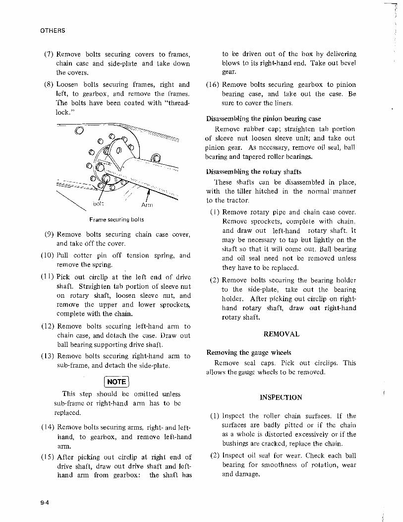
OTHERS
(7) Remove bolts securing covers to frames, chain case and side-plate and take down the covers.
(8) Loosen bolts securing frames, right and left, to gearbox,and remove the frames. The bolts have been coated with "threadlock."
Frame securing bolts
(9) Remove bolts securing chain case cover, and take off the cover.
(10) Pull cotter pin off tension spring, and remove the spring.
(11) Pick out circlip at the left end of drive shaft. Straighten tab portion of sleeve nut on rotary shaft, loosen sleeve nut, and remove the upper and lower sprockets, complete with the chain.
(12) Remove bolts securing left-hand arm to chain case, and detach the case. Draw out ball bearing supporting drive shaft.
(13) Remove bolts securing right-hand arm to sub-frame, and detach the side-plate.
[NOTE) This step should be omitted unless
sub-frame or right-hand arm has to be replaced.
(14) Remove bolts securing arms, right- and lefthand, to gearbox, and remove left-hand arm.
(15) After picking out circlip at right end of drive shaft, draw out drive shaft and lefthand arm from gearbox: the shaft has
9-4
to be driven out of the box by delivering blows to its right-hand end. Take out bevel gear.
(16) Remove bolts securing gearbox to pinion bearing case, and take out the case. Be sure to cover the liners.
Disassembling the pinion bearing case
Remove rubber cap; straighten tab portion of sleeve nut loosen sleeve unit; and take out pinion gear. As necessary, remove oil seal, ball bearing and tapered roller bearings.
Disassembling the rotary shafts
These shafts can be disassembled in place, with the tiller hitched in the normal" maimer to the tractor.
(1) Remove rotary pipe and chain case cover. Remove sprockets, complete with chain, and draw out left-hand rotary shaft. It may be necessary to tap but lightly on the shaft so that it will come out. Ball bearing -and oil seal need not be removed unless they have to be replaced.
(2) Remove bolts securing the bearing holder to the side-plate, take out the bearing holder. After picking out circlip on righthand rotary shaft, draw out right-hand rotary shaft.
REMOVAL
Removing the gauge wheels
Remove seal Caps. Pick out circlips. This allows the gauge wheels to be removed.
INSPECTION
(1) Inspect the roller chain surfaces. If the surfaces are badly pitted or if the chain as a whole is distorted excessively or if the bushings are cracked, replace the chain.
(2) Inspect oil seal for wear. Check each ball bearing for smoothness of rotation, wear and damage.
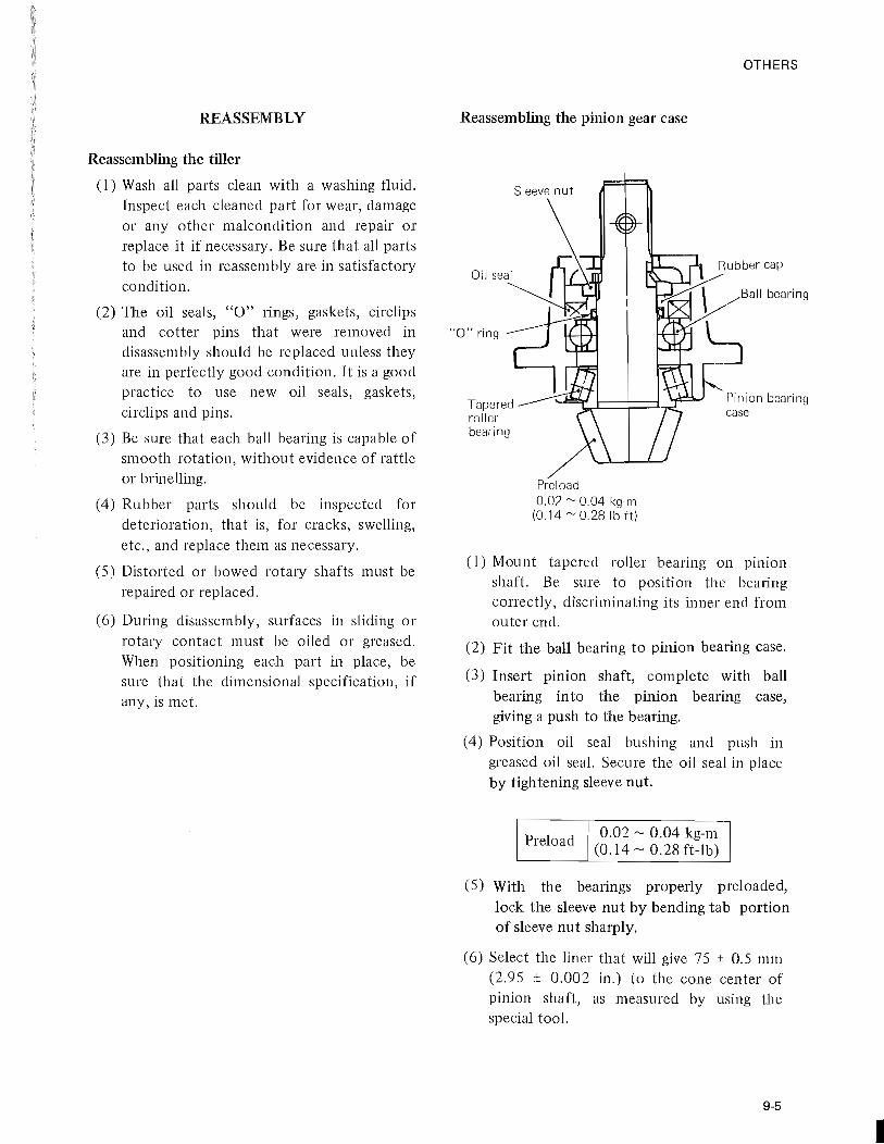
REASSEMBLY
Reassembling the tiller
(1) Wash all parts clean with a washing fluid. Inspect each cleaned part for wear, damage or any other malcondition and repair or replace it if necessary. Be sure that all parts to be used in reassembly are in satisfactory condition.
(2) The oil seals, "0" rings, gaskets, circlips and cotter pins that were removed in disassembly should be replaced unless they are in perfectly good condition. It is a good practice to use new oil seals, gaskets, circlips and pins.
(3) Be sure that each ball bearing is capable of smooth rotation, without evidence of rattle or brinelling.
(4) Rubber parts should be inspected for deterioration, that is, for cracks, swelling, etc., and replace them as necessary.
(5) Distorted or bowed rotmy shafts must be repaired or replaced.
(6) During disassembly, surfaces in sliding or rotary contact must be oiled or greased. When positioning each part in place, be sure that the dimensional specification, if any, is met.
Reassembling the pinion gear case
Oil seal
Tapered roller bearing
Sleeve nut
Preload 0.02 ~ 0.04 kg-rn
(0.14 ~ 0.28 Ib-ft)
OTHERS
(1) Mount tapered roller bearing on pll1lOn shaft. Be sure to position the bearing correctly, discriminating its inner end from outer end.
(2) Fit the ball bearing to pinion bearing case.
(3) Insert pinion shaft, complete with ball bearing into the pinion bearing case, giving a push to the bearing.
(4) Position oil seal bushing and push in greased oil seal. Secure the oil seal in place by tightening sleeve nut.
Preload 0.02 ~ 0.04 kg-m (0.14 ~ 0.28 ft-lb)
(5) With the bearings properly preloaded, lock the sleeve nut by bending tab portion of sleeve nut sharply.
(6) Select the liner that will give 75 ± 0.5 mm (2.95 ± 0.002 in.) to the cone center of pinion shaft, as measured by using the special tool.
9-5
,I

OTHERS
Pinion shaft cone 75 ± 0.05 mm center (2.953 ± 0.002 in.)
Checking cone center
Reassembling the gearbox
9-6
E c EN LDO 00 00 +1 +1
(Y) LD LD 1'-0>
Oil seal
Drive shaft
~..L. _____ _
Arm (LH)
Pinion case
Sleeve nut
Collar
Rest the special tool on the pinion gear, and measure the clearance between forward end of special tool and the face of pinion bearing case, as shown. Select a liner whose thickness is equal to the clearance reading just taken. Insert this liner between the pinion bearing case and the gearbox when fitting the former to the box.
Liner stock is available in these thicknesses:
Thickness
0.1 mm (0.004 in.)
0.2 mm (0.008 in.)
0.4 mm (0.016 in.)
Tightening torque for pinion gear case
Part No.
11363011 000
11363012000
11363013 000
4.0 ~ 4.6 kg-m
(29 ~ 33 ft-lb)
Tapered roller bearing
Backlash
Gearbox
0.25 ~ 0.35 mm (0.01 ~ 0.014 in.)
Arm (RH)

d
(1) After fitting circlip, insert drive shaft into the left side of gearbox. And bevel gear to the shaft. From the right side, fit the other ball bearing to the shaft.
(2) For the right side, insert a liner at right side of ball bearing and fit circlip tentatively. This liner is a tentative one.
(3) Check the backlash of bevel gear in place. On the basis of backlash reading, select the liner that will produce a backlash of anywhere between 0.25 and 0.35 mm (0.01 and 0.014 in.), and replace the tentative inserted liner by this liner.
Bevel gear backlash 0.25 ~ 0.35 mm
(0.01 ~ 0.014 in.)
Liner stock for this adjustment is available in the following thicknesses:
Thickness Part No.
0.2 mm (0.008 in) 69582-00711
0.3 mm (0.012 in) 69582-00712
0.5 mm (0.02 in) 69582-00713
(4) Having determined the liner to be used, fit greased oil seal to left-hand arm. Coat its flange face with sealant, and secure the arm to gearbox.
OTHERS
(5) Put left-hand arm to gearbox so that oil feed pipe is located as shown below, and secure the arm in place with bolts and reamer bolts.
Tightening torque 5.0 ~ 6.0 kg-m (36 ~ 43 ft-lb)
(6) Coat the face of right-hand arm flange with sealant, and secure it to gearbox.
When installing the arm, be sure that it is aligned with the lift rod mounting plate of left-hand arm.
Tightening torque 4.9 ~ 5.7 kg-m
(35 ~ 41 ft-lb)
(7) After tightening the arm securing bolts to the specified torque value, re-check bevel gear backlash to be sure that it is within the specified range. If the backlash is noted off the range, remove the two arms, right and left, and replace the liners by the ones that will satisfy the backlash specification.
(8) Fit circlip to the end of drive shaft.
9-7

OTHERS
Reassembling the chain case
Sprocket Ball bearing
Chain case
Ball bearing
Rotary shaft (LH)
Sprocket
9-8
Oil seal
(I) Grease oil seal, and fit the seal carefully to the lower hole of chain case. Position ball bearing in place by pushing it in, and retain it by installing circlip.
(2) Position left-hand rotary shaft in chain case.
(3) Coat the face of left-hand arm flange with sealant, attach chain case to it, and tighten the securing bolts to this torque value:
4.9 ~ 5.7 kg-m
(35 ~41 ft-lb) Tightening torque
(4) Fit ball bearing to drive shaft.
(5) Put chain over two sprockets, and fit the sprockets to drive shaft and rotary shaft. The boss of each sprocket comes on inner side. Make sure that the sprockets go in smoothly onto the splined shaft ends.
(6) Retain the sprocket on drive shaft by fitting circ1ip. Secure the sprocket on rota·ry shaft by tightening sleeve nut and locking the nut by bending its tab portion sharply.
Tightening torque for sleeve nut
15.0 ~ 20.0 kg-m
(l08 ~ 145 ft-lb)
(7) Install chain tensioning spring and set it by inserting cotter pin.
(8) Secure chain case cover to chain case by tightening cover securing bolts. Before fitting the cover, be sure to coat both faces of the packing with sealant and position the packing neatly on chain case face.
Tightening torque for chain cover securing bolt
Recg the side-plate
Bearing case
1.5 ~ 2.0 kg-m
(11 ~ 14 ft-lb)
Ball bearing
Circlip
Packings
(I) Push greased oil seals into bearing holder at the lower part of side-plate. Insert righthand rotary shaft into the bearing holder, push in ball bearing, and retain the bearing by putting on circlip.
(2) Apply sealant to both faces of bearing holder and side-plate, and attach the holder to side-plate.
(3) Fill the holder with grease. Secure the cover to side-plate by tightening securing bolts to this torque value:
r
1

g
:r
~r
ts
Tightening torque for cover
4.9 ~ 5.7 kg-m (35 ~ 41 ft-lb)
(4) Secure side-plate to right-hand arm.
Tightening torque for side-plate
4.9 ~ 5.7 kg-m (35 ~ 41 ft-lb)
INSTALLATION
Installing the rotary cover
Some of cover securing bolts on the chain case side are through-bolts. Wrap these bolts with sealing tape. Secure the covers to chain case, tightening the bolts temporarily.
Installing the frames
(l) Using bolts coated with "thread-lock," secure frames to gearbox. Position support in place, and lock it by inserting cotter pins. After installing drive shaft and others, secure the frame by tightening its securing bolts. Be sure to lock the frames by the plate.
Tightening torque for frame
4.9 ~ 5.7 kg-m (35 ~ 41 ft-lb)
(2) Install bolts for fastening rotary cover to frames, and tighten cover securing bolts good and hard.
OTHERS
Others
(l) One end of rotary pipe is marked "L-.... , by punching. Position the pipe with its marked end brought to chain case side, and secure it by tightening the bolts to this
torque value:
Tightening torque I for rotary pipe
7.9 ~ 9.2 kg-m (57 ~ 67 ft-lb)
(2) Fill up gearbox and chain case with the prescribed oil.
(3) After installing rotary pipe, turn it by hand to be sure that it is capable of smooth rotation.
(4) Put the castle nut on the tip of depth adjusting handle; make sure that it moves smoothly; and lock the nut by inserting cotter pin.
(S) Mount the gauge wheel support on the support.
(6) Assemble the gauge wheels by reversing the disassembling procedure.
9-9

r OTHERS
SPECIFICATIONS
Model 2PR-lllOS
Type Side drive type rotary tiller
Applicable tractor MT160/D, MT180jD and MT180H/HD
Mounting method Special 2-point hitch
Overall length 1210 (47.64)
Overall width mm (in.) 1230 (48.41) Dimensions
, 1
Overall height 800 (31.50)
Weight kg (lb) 136 (299.8)
Tilling width 1100 (43.31)
Tilling depth mm (in.) 150 (5.91)
Diameter 450 (17.7)
Number of tines 28
Drive system Universal joint spiral bevel gear, chain side drive --
Depth control Lifting and lowering of tail wheels with a handle
Tilling shaft C-l 178 173
Incase of MT180H revolution at C-2 rpm 263 339 rated engine rpm
C-3 430
Tilling tines Holder pitch 46.5 (1.8)
c-i 112 (4.6)
F-l C-2 168 (3.1)
C-3 280 (1.9)
C-l mm (in.)
76 (7.0) Tilling
F-2 C-2 114 (4.8) pitch C-3 189 (2.9)
C-l 46 (11.9)
F-3 C-2 70 (8.1)
C-3 116 (4.9)
Gear case oil liter (pint)
0.4 (0.85) SAE# 80 ~ 90 gear oil Oil capacities
Chain case oil 0.7 (0.65) SAE# 80 ~ 90 gear oil
These specifications are subject to change without notice.
9-10

OTHERS
FRONT POWER TAKE .. OFF (PTO) KIT
This PTO kit also can be installed on MITSUBISHI tractor (MTI60/D, 180/D, and 180H/HD). The only alteration required for installing the kit is to reposition the flange piece in place by reversing.
Bolt
Spacer
Description This PTO is for making power available at the
front end of the tractor from its engine through the CG rubber coupling provided on crankshaft pulley. With the front PTO kit installed, such an implement as a mower, sweeper, snow blower or the like can be driven from the engine.
Spring washer Rubber coupling
Bolt Crankshaft pulley
I ! \ ' ~ I ~ J' ~,"~"J 'lrll~~-' u1, L ____ _
Sleeve nut
--~-\ \----- - / 'P==~H-------~--l /
I Rubber coupling
Spring washer : \
_~ ____ =J Bolt
Front PTO kit
Disassembly
(I) If the kit includes an electromagnetic clutch, remove the guard and undo the electric cord connection. Slacken "V" belt tensioning pulley, and remove the "V" belt. Loosen lock nut with washer; remove base securing bolts; and take down the clutch.
(2) Remove bolts securing the mounting bracket to chassis, and take down the front
PTO.
(3) Pick out circlip, and draw the shaft out. The shaft may have to be tapped on lightly to make it come out: use a plastic hammer in such a case.
(4) Remove ball bearings, circlips and collar from the bracket.
Reassembly
(1) After fitting circlip to the front end of bracket, insert ball bearing into the bracket.
9·11

'OTHERS
(2) Fit ball bearing collar and ball bearings to the PTO shaft. Insert it into the bracket and retain it in place by putting on circiip.
(3) Fit it to the bracket.
[NOTE] When installing the front PTO, never
loosen 'the nut on engine crankshaft.
(4) Mount the flange together with cap on rubber coupling, bringing its boss to outer side, and secure it to the coupling by tightening three bolts and nuts.
Plain washer Rubber coupling
Tightening bolt \ Crankshaft pulley
~ PUl /====r==d;.Y ",
i rubber coupling
\
Sleeve nut
Tightening bolt for flange
(5) With the flange secured as shown above, install the coupling on crankshaft pulley by tightening its mounting bolts to this torque value:
9-12
Tightening torque for coupling
(NOTE]
4.0 ~ 4.5 kg-m (29 ~ 33 ft-Ib)
a) When installing rubber coupling to crankshaft pulley, be careful not to tighten it together with flange. In other words the flange is to be secured to the coupling and tighten with three sets of bolts and nuts, and the coupling is to be secured to crankshaft pulley and tightened with other three pieces of bolts.
b) The new rubber, coupling comes with a steel band strapped around it. Remove this band after installing and securing the new coupling.
(6) Grease the splines cut in the rear end of PTO shaft, and insert this splined end of it with boot into the splined flange' piece secured to rubber coupling. Keeping PTO shaft level with crankshaft, secure its bracket to chassis by tightening the bracket mounting bolts to this torque value:
Tightening torque for bracket
4.0 ~ 4.5 kg-m (29 ~ 33 ft-lb)
Install the electromagnetic clutch in the order that is reverse of its removal.
[NOTE] When installing the pulley and mag
netic clutch, the core might interfere with the clutch drum being positioned in place. In such case, eliminate the interference by loosening bolts securing the magnetic clutch base in place and displace the base out of the way for the drum. Be sure that the radial clearance between core and drum is uniform all around.
The axial clearance, too, must be uniform all around. To obtain a proper axial clearance, insert a liner between clutch drum and shoulder formed of PTO shaft.
F
'I

>
. • I
J
Electrical wiring for Front PTO kit
O.85R
Stick on the instrument panel
O.85B
I nstall this to the Instrument pannel
OTHERS
O.85R O.85R
1.25G
9-13

F
I

F -
, I .. I

MITSUBISHI AGRICULTURAL MACHINERY Co., LTD. 6-3, KANADA KAJICHO 3-CHOME, CHIYODA-KU
TOKYO JAPAN Publication No. '83-2-300(R) Printed in Japan
....,


![l j b g Z j g h ] i p b Z e b k l Z - Fermer.Ru](https://img.pdfslide.us/doc/110x75/6276c67810629731a438759b/l-j-b-g-z-j-g-h-i-p-b-z-e-b-k-l-z-.jpg)