Embed Size (px)
Citation preview
Imperial College of Science, Technology and Medicine(University of London)
Department of Computing
Translating between XML and RelationalDatabases using XML Schema and Automed
Andrew Charles Smithacs203
Submitted in partial fulfillment of the requirements for the MSc Degree in Advanced Computing of theUniversity of London and for the Diploma of
Imperial College of Science, Technology and Medicine.
September 2004
Acknowledgements
I would like to thank my supervisor, Peter McBrien, for his support during this project and hishelp with the Automed API. I would also like to thank Lucas Zamboulis for his help with theXML queries and Nicolas Debarnot for his help with LATEX.
1
Contents
1 Introduction 8
2 XML and RDBMS 11
2.1 Motivating Example . . . . . . . . . . . . . . . . . . . . . . . . . . . . . . . . . . . 11
2.2 RDBMS . . . . . . . . . . . . . . . . . . . . . . . . . . . . . . . . . . . . . . . . . . 11
2.3 XML . . . . . . . . . . . . . . . . . . . . . . . . . . . . . . . . . . . . . . . . . . . . 12
2.3.1 Constraining XML . . . . . . . . . . . . . . . . . . . . . . . . . . . . . . . . 12
2.3.2 XML Schema . . . . . . . . . . . . . . . . . . . . . . . . . . . . . . . . . . . 12
2.4 Representing Data Graphically . . . . . . . . . . . . . . . . . . . . . . . . . . . . . 17
2.4.1 XPath . . . . . . . . . . . . . . . . . . . . . . . . . . . . . . . . . . . . . . . 18
2.4.2 XMLSPY . . . . . . . . . . . . . . . . . . . . . . . . . . . . . . . . . . . . . 19
2.4.3 Entity-Relationship Models . . . . . . . . . . . . . . . . . . . . . . . . . . . 19
2.5 Querying . . . . . . . . . . . . . . . . . . . . . . . . . . . . . . . . . . . . . . . . . 19
2.5.1 XQuery . . . . . . . . . . . . . . . . . . . . . . . . . . . . . . . . . . . . . . 20
2.5.2 SQL . . . . . . . . . . . . . . . . . . . . . . . . . . . . . . . . . . . . . . . . 20
3 Moving Data between RDBMSs and XML 21
3.1 XML/Relational Schemas . . . . . . . . . . . . . . . . . . . . . . . . . . . . . . . . 21
3.1.1 Differences between XML and relational schemas . . . . . . . . . . . . . . . 21
3.2 The Translation Process . . . . . . . . . . . . . . . . . . . . . . . . . . . . . . . . . 21
3.3 Main problems . . . . . . . . . . . . . . . . . . . . . . . . . . . . . . . . . . . . . . 22
3.4 Existing Approaches . . . . . . . . . . . . . . . . . . . . . . . . . . . . . . . . . . . 22
3.4.1 Storing XML in relational databases . . . . . . . . . . . . . . . . . . . . . . 23
3.4.2 Exporting relational data to XML . . . . . . . . . . . . . . . . . . . . . . . 24
3.4.3 Generating an XML schema from a Relational schema . . . . . . . . . . . . 26
3.5 Choosing the most appropriate schema . . . . . . . . . . . . . . . . . . . . . . . . . 26
3.5.1 LegoDB . . . . . . . . . . . . . . . . . . . . . . . . . . . . . . . . . . . . . . 29
3.6 Querying the data . . . . . . . . . . . . . . . . . . . . . . . . . . . . . . . . . . . . 29
4 An Approach to the Translation Using Graphical Techniques 30
4.1 XML to Relational . . . . . . . . . . . . . . . . . . . . . . . . . . . . . . . . . . . . 30
4.2 Relational to XML Schema . . . . . . . . . . . . . . . . . . . . . . . . . . . . . . . 31
2
4.3 The Appropriateness of the Schema . . . . . . . . . . . . . . . . . . . . . . . . . . 31
4.4 Querying the Schema . . . . . . . . . . . . . . . . . . . . . . . . . . . . . . . . . . . 31
4.5 An Abstract Data Model . . . . . . . . . . . . . . . . . . . . . . . . . . . . . . . . 31
5 HDM 32
5.1 Higher Level Modeling Languages in HDM . . . . . . . . . . . . . . . . . . . . . . 33
5.2 The Relational Model . . . . . . . . . . . . . . . . . . . . . . . . . . . . . . . . . . 34
5.2.1 Unique Relational Tuples . . . . . . . . . . . . . . . . . . . . . . . . . . . . 35
5.2.2 Relational Tuples with Repeated Elements . . . . . . . . . . . . . . . . . . 35
5.2.3 More Complex Relational Tuples . . . . . . . . . . . . . . . . . . . . . . . . 35
5.3 XML . . . . . . . . . . . . . . . . . . . . . . . . . . . . . . . . . . . . . . . . . . . . 37
6 XML Schema 39
6.1 Some Examples . . . . . . . . . . . . . . . . . . . . . . . . . . . . . . . . . . . . . . 40
6.1.1 One Complex Type to represent the whole schema . . . . . . . . . . . . . . 40
6.1.2 A Complex Type for each part of the schema with no nesting . . . . . . . . 42
6.1.3 Keyrefs . . . . . . . . . . . . . . . . . . . . . . . . . . . . . . . . . . . . . . 42
6.1.4 Nesting . . . . . . . . . . . . . . . . . . . . . . . . . . . . . . . . . . . . . . 43
6.2 The Primitive Transformations . . . . . . . . . . . . . . . . . . . . . . . . . . . . . 43
6.2.1 Type . . . . . . . . . . . . . . . . . . . . . . . . . . . . . . . . . . . . . . . . 44
6.2.2 Element . . . . . . . . . . . . . . . . . . . . . . . . . . . . . . . . . . . . . . 44
6.2.3 Attribute . . . . . . . . . . . . . . . . . . . . . . . . . . . . . . . . . . . . . 44
6.2.4 ComplexTypeNest . . . . . . . . . . . . . . . . . . . . . . . . . . . . . . . . 44
6.2.5 Key . . . . . . . . . . . . . . . . . . . . . . . . . . . . . . . . . . . . . . . . 45
6.2.6 KeyRef . . . . . . . . . . . . . . . . . . . . . . . . . . . . . . . . . . . . . . 45
6.3 Composite Transformations . . . . . . . . . . . . . . . . . . . . . . . . . . . . . . . 45
6.3.1 Transforming an Element to an Attribute . . . . . . . . . . . . . . . . . . . 45
7 Inter-model Transformations in HDM 47
7.1 Transforming between XML Schema and the Relational model . . . . . . . . . . . 47
7.1.1 An example . . . . . . . . . . . . . . . . . . . . . . . . . . . . . . . . . . . . 49
8 Case Studies 51
8.1 Derived Complex Types . . . . . . . . . . . . . . . . . . . . . . . . . . . . . . . . . 51
3

8.2 Complex Types with the same structure but different names . . . . . . . . . . . . . 52
8.3 Keys and Keyrefs with a Choice in the XPath of the Selector . . . . . . . . . . . . 54
8.4 X.521 and LDAP . . . . . . . . . . . . . . . . . . . . . . . . . . . . . . . . . . . . . 56
8.4.1 Self referencing and Recursion . . . . . . . . . . . . . . . . . . . . . . . . . 57
8.4.2 LDAP . . . . . . . . . . . . . . . . . . . . . . . . . . . . . . . . . . . . . . . 57
9 Implementation 60
9.1 Automed . . . . . . . . . . . . . . . . . . . . . . . . . . . . . . . . . . . . . . . . . 61
9.1.1 IQL . . . . . . . . . . . . . . . . . . . . . . . . . . . . . . . . . . . . . . . . 62
9.2 Representing a Relational Schema in Automed . . . . . . . . . . . . . . . . . . . . 62
9.3 The Automed XML Schema Wrapper . . . . . . . . . . . . . . . . . . . . . . . . . 62
9.4 The HDM transformations . . . . . . . . . . . . . . . . . . . . . . . . . . . . . . . . 63
9.4.1 Transforming between XML Schema and HDM . . . . . . . . . . . . . . . . 63
9.4.2 Transforming between HDM and SQL . . . . . . . . . . . . . . . . . . . . . 64
9.5 XSDOM . . . . . . . . . . . . . . . . . . . . . . . . . . . . . . . . . . . . . . . . . . 64
9.5.1 Element . . . . . . . . . . . . . . . . . . . . . . . . . . . . . . . . . . . . . . 65
9.5.2 Attribute . . . . . . . . . . . . . . . . . . . . . . . . . . . . . . . . . . . . . 65
9.5.3 ComplexType . . . . . . . . . . . . . . . . . . . . . . . . . . . . . . . . . . . 65
9.5.4 Document . . . . . . . . . . . . . . . . . . . . . . . . . . . . . . . . . . . . . 65
9.5.5 Converting from XML Schema API to XSDOM . . . . . . . . . . . . . . . . 65
9.5.6 XSDOM to Automed XML Schema . . . . . . . . . . . . . . . . . . . . . . 66
9.5.7 Automed XML Schema to XSDOM . . . . . . . . . . . . . . . . . . . . . . 66
9.5.8 XSDOM to JTree . . . . . . . . . . . . . . . . . . . . . . . . . . . . . . . . . 66
9.6 GUI . . . . . . . . . . . . . . . . . . . . . . . . . . . . . . . . . . . . . . . . . . . . 67
9.6.1 Operations in the GUI . . . . . . . . . . . . . . . . . . . . . . . . . . . . . . 67
9.7 Transformations in the GUI . . . . . . . . . . . . . . . . . . . . . . . . . . . . . . . 68
9.7.1 Drag and Drop . . . . . . . . . . . . . . . . . . . . . . . . . . . . . . . . . . 68
9.7.2 Making an attribute a key . . . . . . . . . . . . . . . . . . . . . . . . . . . . 68
9.7.3 Adding a keyref . . . . . . . . . . . . . . . . . . . . . . . . . . . . . . . . . . 68
9.8 Materialising the Automed XML Schema . . . . . . . . . . . . . . . . . . . . . . . 68
9.9 Creating SQL tables . . . . . . . . . . . . . . . . . . . . . . . . . . . . . . . . . . . 70
4
10 Conclusions 71
10.1 Transforming the Schemas . . . . . . . . . . . . . . . . . . . . . . . . . . . . . . . . 71
10.2 Choosing the Most Appropriate Schema . . . . . . . . . . . . . . . . . . . . . . . . 72
10.3 Querying the Data . . . . . . . . . . . . . . . . . . . . . . . . . . . . . . . . . . . . 72
10.4 Future work . . . . . . . . . . . . . . . . . . . . . . . . . . . . . . . . . . . . . . . . 72
5
List of Figures
1 A simple XML Schema fragment . . . . . . . . . . . . . . . . . . . . . . . . . . . . 9
2 SQL definition of relational table . . . . . . . . . . . . . . . . . . . . . . . . . . . . 10
3 HDM representation of simple XML Schema fragment and relational table . . . . . 10
4 Tables and SQL DDL statements for the shoes relational database . . . . . . . . . 13
5 shoes.xml: XML document of shoe data . . . . . . . . . . . . . . . . . . . . . . . . 14
6 DTD for shoe example . . . . . . . . . . . . . . . . . . . . . . . . . . . . . . . . . . 15
7 shoes.xsd: XML Schema for shoe example . . . . . . . . . . . . . . . . . . . . . . . 16
8 XPath Data Model of XML in Figure 5 . . . . . . . . . . . . . . . . . . . . . . . . 18
9 XPath Data Model of a portion of the XML Schema in Figure 7 . . . . . . . . . . 18
10 xmlspy graphical representation of an XML Schema fragment . . . . . . . . . . . . 19
11 ER Data Model of the RDBMS Schema in Figure 4 . . . . . . . . . . . . . . . . . . 19
12 Edge Schema representation of the XML from Figure 5 . . . . . . . . . . . . . . . . 24
13 Element Schema representation of Figure 5 . . . . . . . . . . . . . . . . . . . . . . 25
14 SQL/XML query and result . . . . . . . . . . . . . . . . . . . . . . . . . . . . . . . 26
15 XML Schema created by Lui et al. method . . . . . . . . . . . . . . . . . . . . . . 27
16 XML conforming to the XML Schema in Figure 15 . . . . . . . . . . . . . . . . . . 28
17 A screen shot of the Automed editor . . . . . . . . . . . . . . . . . . . . . . . . . . 32
18 HDM representation of simple data . . . . . . . . . . . . . . . . . . . . . . . . . . . 35
19 HDM representation of foreign key type link . . . . . . . . . . . . . . . . . . . . . . 36
20 HDM representation of nesting type link . . . . . . . . . . . . . . . . . . . . . . . . 36
21 HDM representation of the XML in Figure 5 . . . . . . . . . . . . . . . . . . . . . 37
22 HDM of the address schema . . . . . . . . . . . . . . . . . . . . . . . . . . . . . . . 52
23 ER representation of address schema . . . . . . . . . . . . . . . . . . . . . . . . . . 53
24 XML Schema fragment showing a choice in the selector XPath . . . . . . . . . . . 55
25 HDM of the vehicle schema . . . . . . . . . . . . . . . . . . . . . . . . . . . . . . . 55
26 SQL tables representing an XML Schema with a choice in one it’s key selectors . . 56
27 A portion of the X521 naming standard . . . . . . . . . . . . . . . . . . . . . . . . 57
28 XML Schema fragment showing a portion of the X521 standard . . . . . . . . . . . 58
29 XML Schema fragment showing choice tags . . . . . . . . . . . . . . . . . . . . . . 59
30 The class hierarchy . . . . . . . . . . . . . . . . . . . . . . . . . . . . . . . . . . . . 60
31 How XML Schema API components of a complex type map to XSDOM . . . . . . 65
6
32 JTrees showing simple XML Schema transformations . . . . . . . . . . . . . . . . . 67
List of Tables
1 Definition of relational model constructs in the HDM . . . . . . . . . . . . . . . . . 34
2 Definition of XML constructs in the HDM . . . . . . . . . . . . . . . . . . . . . . . 37
3 Definition of XML Schema constructs in the HDM . . . . . . . . . . . . . . . . . . 41
4 HDM schema instance of the XML Schema document in Figure 7 . . . . . . . . . . 41
5 HDM schema instance of the XML document in Figure 5 . . . . . . . . . . . . . . 42
7
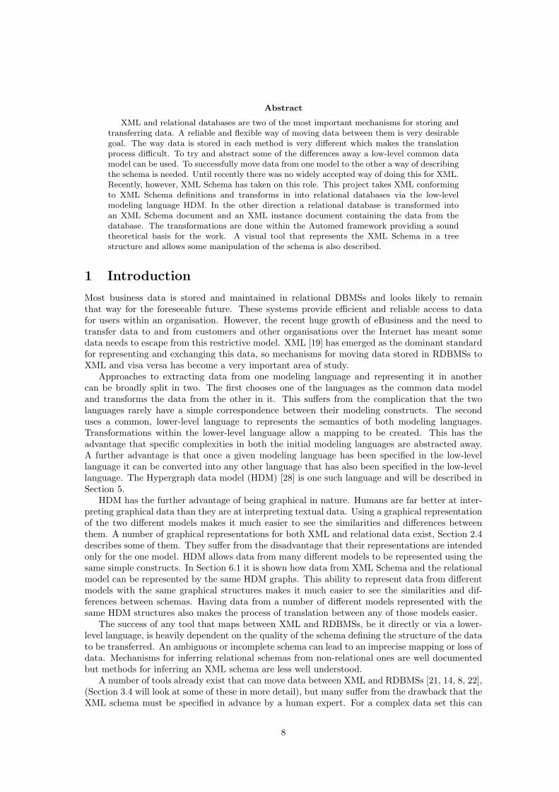
Abstract
XML and relational databases are two of the most important mechanisms for storing andtransferring data. A reliable and flexible way of moving data between them is very desirablegoal. The way data is stored in each method is very different which makes the translationprocess difficult. To try and abstract some of the differences away a low-level common datamodel can be used. To successfully move data from one model to the other a way of describingthe schema is needed. Until recently there was no widely accepted way of doing this for XML.Recently, however, XML Schema has taken on this role. This project takes XML conformingto XML Schema definitions and transforms in into relational databases via the low-levelmodeling language HDM. In the other direction a relational database is transformed intoan XML Schema document and an XML instance document containing the data from thedatabase. The transformations are done within the Automed framework providing a soundtheoretical basis for the work. A visual tool that represents the XML Schema in a treestructure and allows some manipulation of the schema is also described.
1 Introduction
Most business data is stored and maintained in relational DBMSs and looks likely to remainthat way for the foreseeable future. These systems provide efficient and reliable access to datafor users within an organisation. However, the recent huge growth of eBusiness and the need totransfer data to and from customers and other organisations over the Internet has meant somedata needs to escape from this restrictive model. XML [19] has emerged as the dominant standardfor representing and exchanging this data, so mechanisms for moving data stored in RDBMSs toXML and visa versa has become a very important area of study.
Approaches to extracting data from one modeling language and representing it in anothercan be broadly split in two. The first chooses one of the languages as the common data modeland transforms the data from the other in it. This suffers from the complication that the twolanguages rarely have a simple correspondence between their modeling constructs. The seconduses a common, lower-level language to represents the semantics of both modeling languages.Transformations within the lower-level language allow a mapping to be created. This has theadvantage that specific complexities in both the initial modeling languages are abstracted away.A further advantage is that once a given modeling language has been specified in the low-levellanguage it can be converted into any other language that has also been specified in the low-levellanguage. The Hypergraph data model (HDM) [28] is one such language and will be described inSection 5.
HDM has the further advantage of being graphical in nature. Humans are far better at inter-preting graphical data than they are at interpreting textual data. Using a graphical representationof the two different models makes it much easier to see the similarities and differences betweenthem. A number of graphical representations for both XML and relational data exist, Section 2.4describes some of them. They suffer from the disadvantage that their representations are intendedonly for the one model. HDM allows data from many different models to be represented using thesame simple constructs. In Section 6.1 it is shown how data from XML Schema and the relationalmodel can be represented by the same HDM graphs. This ability to represent data from differentmodels with the same graphical structures makes it much easier to see the similarities and dif-ferences between schemas. Having data from a number of different models represented with thesame HDM structures also makes the process of translation between any of those models easier.
The success of any tool that maps between XML and RDBMSs, be it directly or via a lower-level language, is heavily dependent on the quality of the schema defining the structure of the datato be transferred. An ambiguous or incomplete schema can lead to an imprecise mapping or loss ofdata. Mechanisms for inferring relational schemas from non-relational ones are well documentedbut methods for inferring an XML schema are less well understood.
A number of tools already exist that can move data between XML and RDBMSs [21, 14, 8, 22],(Section 3.4 will look at some of these in more detail), but many suffer from the drawback that theXML schema must be specified in advance by a human expert. For a complex data set this can
8
<xsd:complexType name="shoes"><xsd:sequence><xsd:element name="price" type="xsd:integer" /><xsd:element name="colour" type="xsd:string" />
</xsd:sequence><xsd:attribute name="shoeid" type="xsd:integer" />
</xsd:complexType>
<xsd:element name="shoe" type="shoes"></xsd:key name="unique_shoeid"><xsd:selector xpath="./" /><xsd:field xpath="@shoeid" />
</xsd:key></xsd:element>
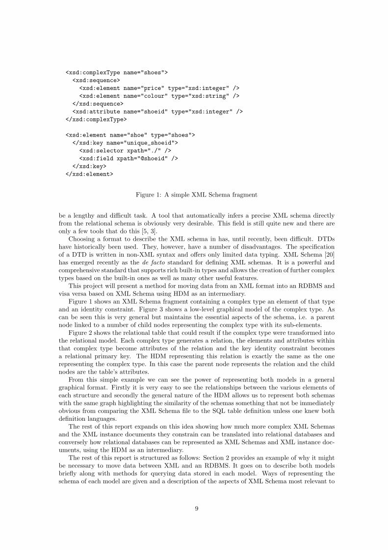
Figure 1: A simple XML Schema fragment
be a lengthy and difficult task. A tool that automatically infers a precise XML schema directlyfrom the relational schema is obviously very desirable. This field is still quite new and there areonly a few tools that do this [5, 3].
Choosing a format to describe the XML schema in has, until recently, been difficult. DTDshave historically been used. They, however, have a number of disadvantages. The specificationof a DTD is written in non-XML syntax and offers only limited data typing. XML Schema [20]has emerged recently as the de facto standard for defining XML schemas. It is a powerful andcomprehensive standard that supports rich built-in types and allows the creation of further complextypes based on the built-in ones as well as many other useful features.
This project will present a method for moving data from an XML format into an RDBMS andvisa versa based on XML Schema using HDM as an intermediary.
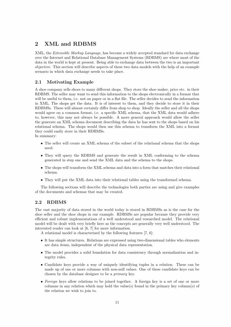
Figure 1 shows an XML Schema fragment containing a complex type an element of that typeand an identity constraint. Figure 3 shows a low-level graphical model of the complex type. Ascan be seen this is very general but maintains the essential aspects of the schema, i.e. a parentnode linked to a number of child nodes representing the complex type with its sub-elements.
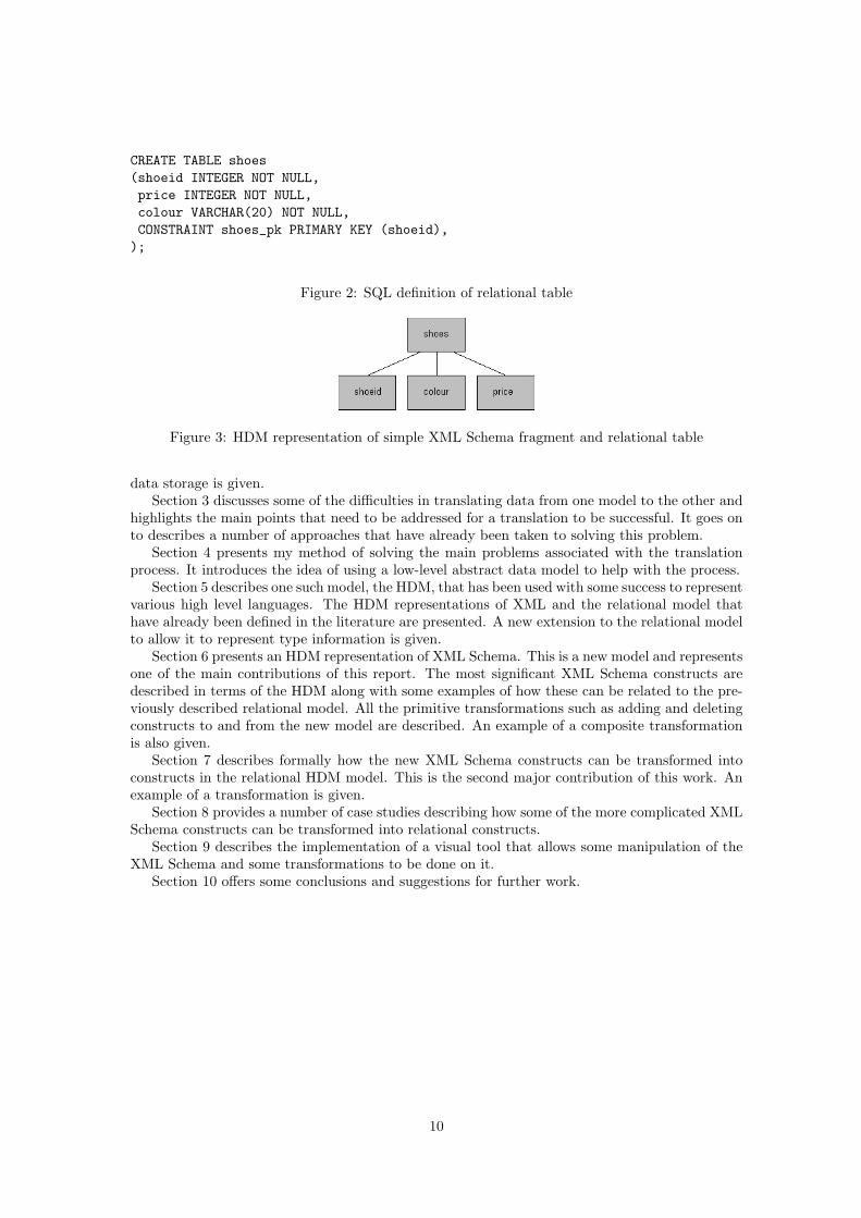
Figure 2 shows the relational table that could result if the complex type were transformed intothe relational model. Each complex type generates a relation, the elements and attributes withinthat complex type become attributes of the relation and the key identity constraint becomesa relational primary key. The HDM representing this relation is exactly the same as the onerepresenting the complex type. In this case the parent node represents the relation and the childnodes are the table’s attributes.
From this simple example we can see the power of representing both models in a generalgraphical format. Firstly it is very easy to see the relationships between the various elements ofeach structure and secondly the general nature of the HDM allows us to represent both schemaswith the same graph highlighting the similarity of the schemas something that not be immediatelyobvious from comparing the XML Schema file to the SQL table definition unless one knew bothdefinition languages.
The rest of this report expands on this idea showing how much more complex XML Schemasand the XML instance documents they constrain can be translated into relational databases andconversely how relational databases can be represented as XML Schemas and XML instance doc-uments, using the HDM as an intermediary.
The rest of this report is structured as follows: Section 2 provides an example of why it mightbe necessary to move data between XML and an RDBMS. It goes on to describe both modelsbriefly along with methods for querying data stored in each model. Ways of representing theschema of each model are given and a description of the aspects of XML Schema most relevant to
9
CREATE TABLE shoes(shoeid INTEGER NOT NULL,price INTEGER NOT NULL,colour VARCHAR(20) NOT NULL,CONSTRAINT shoes_pk PRIMARY KEY (shoeid),);
Figure 2: SQL definition of relational table
Figure 3: HDM representation of simple XML Schema fragment and relational table
data storage is given.Section 3 discusses some of the difficulties in translating data from one model to the other and
highlights the main points that need to be addressed for a translation to be successful. It goes onto describes a number of approaches that have already been taken to solving this problem.
Section 4 presents my method of solving the main problems associated with the translationprocess. It introduces the idea of using a low-level abstract data model to help with the process.
Section 5 describes one such model, the HDM, that has been used with some success to representvarious high level languages. The HDM representations of XML and the relational model thathave already been defined in the literature are presented. A new extension to the relational modelto allow it to represent type information is given.
Section 6 presents an HDM representation of XML Schema. This is a new model and representsone of the main contributions of this report. The most significant XML Schema constructs aredescribed in terms of the HDM along with some examples of how these can be related to the pre-viously described relational model. All the primitive transformations such as adding and deletingconstructs to and from the new model are described. An example of a composite transformationis also given.
Section 7 describes formally how the new XML Schema constructs can be transformed intoconstructs in the relational HDM model. This is the second major contribution of this work. Anexample of a transformation is given.
Section 8 provides a number of case studies describing how some of the more complicated XMLSchema constructs can be transformed into relational constructs.
Section 9 describes the implementation of a visual tool that allows some manipulation of theXML Schema and some transformations to be done on it.
Section 10 offers some conclusions and suggestions for further work.
10
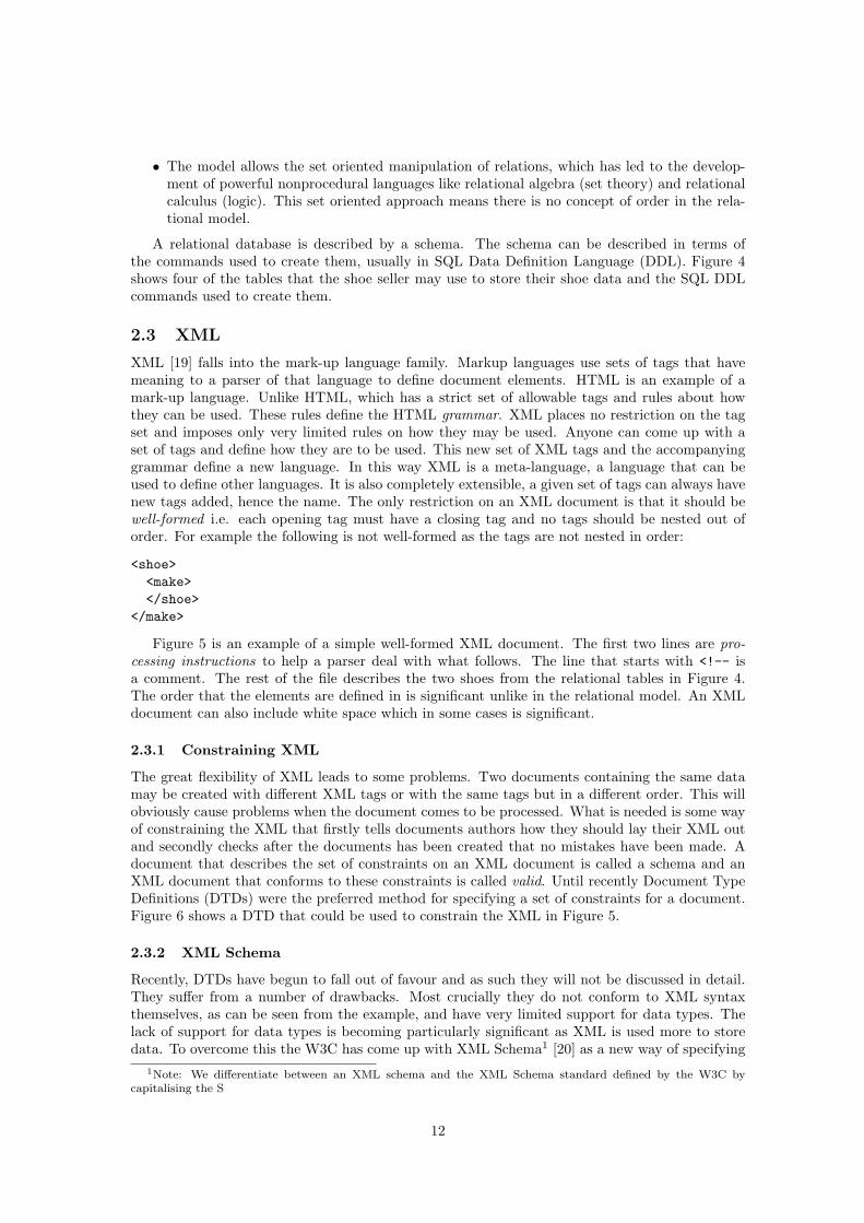
2 XML and RDBMS
XML, the Extensible Markup Language, has become a widely accepted standard for data exchangeover the Internet and Relational Database Management Systems (RDBMS) are where most of thedata in the world is kept at present. Being able to exchange data between the two is an importantobjective. This section will describe aspects of these two data models with the help of an examplescenario in which data exchange needs to take place.
2.1 Motivating Example
A shoe company sells shoes to many different shops. They store the shoe maker, price etc. in theirRDBMS. The seller may want to send this information to the shops electronically in a format thatwill be useful to them, i.e. not on paper or in a flat file. The seller decides to send the informationin XML. The shops get the data. It is of interest to them, and they decide to store it in theirRDBMSs. These will almost certainly differ from shop to shop. Ideally the seller and all the shopswould agree on a common format, i.e. a specific XML schema, that the XML data would adhereto, however, this may not always be possible. A more general approach would allow the sellerthe generate an XML schema document describing the data he has sent to the shops based on hisrelational schema. The shops would then use this schema to transform the XML into a formatthey could easily store in their RDBMSs.In summary:
• The seller will create an XML schema of the subset of the relational schema that the shopsneed.
• They will query the RDBMS and generate the result in XML conforming to the schemagenerated in step one and send the XML data and the schema to the shops.
• The shops will transform the XML schema and data into a form that matches their relationalschema.
• They will put the XML data into their relational tables using the transformed schema.
The following sections will describe the technologies both parties are using and give examplesof the documents and schemas that may be created.
2.2 RDBMS
The vast majority of data stored in the world today is stored in RDBMSs as is the case for theshoe seller and the shoe shops in our example. RDBMSs are popular because they provide veryefficient and robust implementations of a well understood and researched model. The relationalmodel will be dealt with very briefly here as the concepts are generally very well understood. Theinterested reader can look at [6, 7] for more information.
A relational model is characterised by the following features [7, 6]:
• It has simple structures. Relations are expressed using two-dimensional tables who elementsare data items, independent of the physical data representation.
• The model provides a solid foundation for data consistency through normalization and in-tegrity rules.
• Candidate keys provide a way of uniquely identifying tuples in a relation. These can bemade up of one or more columns with non-null values. One of these candidate keys can bechosen by the database designer to be a primary key.
• Foreign keys allow relations to be joined together. A foreign key is a set of one or morecolumns in any relation which may hold the value(s) found in the primary key column(s) ofthe relation we wish to join to.
11
• The model allows the set oriented manipulation of relations, which has led to the develop-ment of powerful nonprocedural languages like relational algebra (set theory) and relationalcalculus (logic). This set oriented approach means there is no concept of order in the rela-tional model.
A relational database is described by a schema. The schema can be described in terms ofthe commands used to create them, usually in SQL Data Definition Language (DDL). Figure 4shows four of the tables that the shoe seller may use to store their shoe data and the SQL DDLcommands used to create them.
2.3 XML
XML [19] falls into the mark-up language family. Markup languages use sets of tags that havemeaning to a parser of that language to define document elements. HTML is an example of amark-up language. Unlike HTML, which has a strict set of allowable tags and rules about howthey can be used. These rules define the HTML grammar. XML places no restriction on the tagset and imposes only very limited rules on how they may be used. Anyone can come up with aset of tags and define how they are to be used. This new set of XML tags and the accompanyinggrammar define a new language. In this way XML is a meta-language, a language that can beused to define other languages. It is also completely extensible, a given set of tags can always havenew tags added, hence the name. The only restriction on an XML document is that it should bewell-formed i.e. each opening tag must have a closing tag and no tags should be nested out oforder. For example the following is not well-formed as the tags are not nested in order:
<shoe><make></shoe>
</make>
Figure 5 is an example of a simple well-formed XML document. The first two lines are pro-cessing instructions to help a parser deal with what follows. The line that starts with <!-- isa comment. The rest of the file describes the two shoes from the relational tables in Figure 4.The order that the elements are defined in is significant unlike in the relational model. An XMLdocument can also include white space which in some cases is significant.
2.3.1 Constraining XML
The great flexibility of XML leads to some problems. Two documents containing the same datamay be created with different XML tags or with the same tags but in a different order. This willobviously cause problems when the document comes to be processed. What is needed is some wayof constraining the XML that firstly tells documents authors how they should lay their XML outand secondly checks after the documents has been created that no mistakes have been made. Adocument that describes the set of constraints on an XML document is called a schema and anXML document that conforms to these constraints is called valid. Until recently Document TypeDefinitions (DTDs) were the preferred method for specifying a set of constraints for a document.Figure 6 shows a DTD that could be used to constrain the XML in Figure 5.
2.3.2 XML Schema
Recently, DTDs have begun to fall out of favour and as such they will not be discussed in detail.They suffer from a number of drawbacks. Most crucially they do not conform to XML syntaxthemselves, as can be seen from the example, and have very limited support for data types. Thelack of support for data types is becoming particularly significant as XML is used more to storedata. To overcome this the W3C has come up with XML Schema1 [20] as a new way of specifying
1Note: We differentiate between an XML schema and the XML Schema standard defined by the W3C bycapitalising the S
12
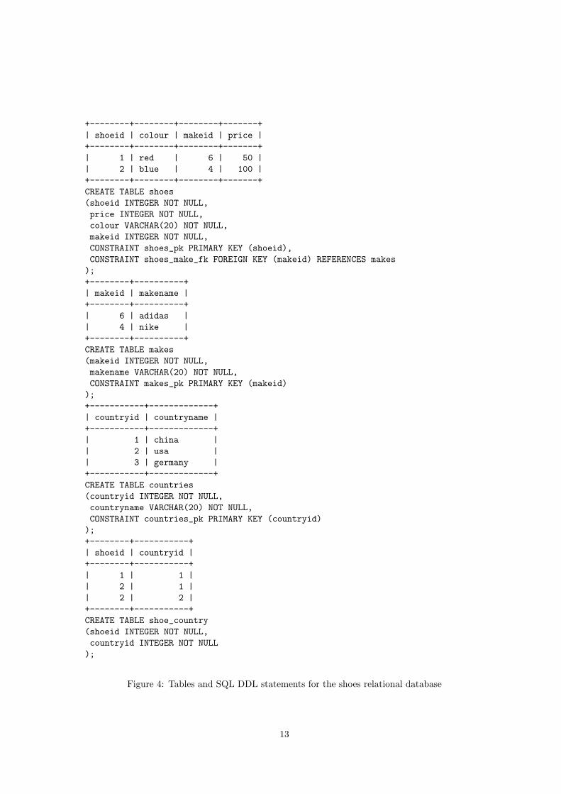
+--------+--------+--------+-------+| shoeid | colour | makeid | price |+--------+--------+--------+-------+| 1 | red | 6 | 50 || 2 | blue | 4 | 100 |+--------+--------+--------+-------+CREATE TABLE shoes(shoeid INTEGER NOT NULL,price INTEGER NOT NULL,colour VARCHAR(20) NOT NULL,makeid INTEGER NOT NULL,CONSTRAINT shoes_pk PRIMARY KEY (shoeid),CONSTRAINT shoes_make_fk FOREIGN KEY (makeid) REFERENCES makes);+--------+----------+| makeid | makename |+--------+----------+| 6 | adidas || 4 | nike |+--------+----------+CREATE TABLE makes(makeid INTEGER NOT NULL,makename VARCHAR(20) NOT NULL,CONSTRAINT makes_pk PRIMARY KEY (makeid));+-----------+-------------+| countryid | countryname |+-----------+-------------+| 1 | china || 2 | usa || 3 | germany |+-----------+-------------+CREATE TABLE countries(countryid INTEGER NOT NULL,countryname VARCHAR(20) NOT NULL,CONSTRAINT countries_pk PRIMARY KEY (countryid));+--------+-----------+| shoeid | countryid |+--------+-----------+| 1 | 1 || 2 | 1 || 2 | 2 |+--------+-----------+CREATE TABLE shoe_country(shoeid INTEGER NOT NULL,countryid INTEGER NOT NULL);
Figure 4: Tables and SQL DDL statements for the shoes relational database
13

<?xml version="1.0" encoding="UTF-8"?>
<shoes xmlns:xsi="http://www.w3.org/2001/XMLSchema-instance"xsi:noNamespaceSchemaLocation="file:shoes.xsd"><!-- XML representation of two shoes -->
<shoe shoeid="1"><make makeid="6">
<makename>adidas</makename></make><price>50</price><colour>red</colour><country>china</country>
</shoe><shoe shoeid="2"><make makeid="4"><makename>nike</makename>
</make><price>100</price><colour>blue</colour><country>usa</country><country>china</country>
</shoe></shoes>
Figure 5: shoes.xml: XML document of shoe data
XML constraints. Figure 7 is an example of the XML Schema used to constrain the XML shoedocument in Figure 5. Given that the XML in Figure 5 conforms to the constraints we can say thatit is both well-formed and valid. Note that all XML Schema language components in Figure 7 arepreceded by xsd: this tells the parser that they come from the XML Schema namespace definedin the processing instruction in line 2. See [19] for more information about namespaces.
The XML Schema standard is extremely comprehensive and allows very rich constraints to becreated. Of particular interest to data exchange and transformation are XML Schema’s supportfor both simple and complex data types and its support for key and unique constraints. As canbe seen from the example XML Schema documents also conform to standard XML syntax whichmeans they can be parsed by existing XML tools.
The complexity of the XML Schema standard has led a number of authors to suggest portionsof the standard that can be easily understood but that are still able to offer sufficient power forspecific tasks such as data storage [30, 24].
The example XML Schema includes the components deemed to be of most use when using XMLSchema to define data storage and transfer schemas. Other authors[14, 33] have used simpler butnon-standard schemas to constrain XML. I felt it was better to work with a portion of an acceptedstandard schema definition language. As time allows this work can be extended to incorporatemore of the XML Schema standard.
The following is a list of the XML Schema constructs I will be discussing in the rest if thisreport.
• element: These define the name and type of elements that may be present in an XML doc-ument conforming to this schema. Elements can be of simple or complex type. Occurrenceconstraints determines how often an element must occur. Setting minOccurs to 0 will makethe element optional. Setting maxOccurs to n means the element can be repeated n times.Setting it to unbounded means the element can occur an unlimited number of times.
14

<?xml version=’1.0’ encoding=’UTF-8’?>
<!ELEMENT country (#PCDATA)*>
<!ELEMENT colour (#PCDATA)>
<!ELEMENT price (#PCDATA)>
<!ELEMENT makename (#PCDATA)>
<!ELEMENT make (makename)><!ATTLIST make
makeid CDATA #IMPLIED>
<!ELEMENT shoe (country|colour|price|make)><!ATTLIST shoe
shoeid CDATA #IMPLIED>
<!ELEMENT shoes (shoe)*><!ATTLIST shoes
xsi:noNamespaceSchemaLocation CDATA #IMPLIEDxmlns:xsi CDATA #IMPLIED
>
Figure 6: DTD for shoe example
15

<?xml version="1.0" encoding="UTF-8"?>
<xsd:schema xmlns:xsd="http://www.w3.org/2001/XMLSchema">
<xsd:simpleType name = "validCountries">
<xsd:restriction base="xsd:string">
<xsd:enumeration value="china" />
<xsd:enumeration value="germany" />
<xsd:enumeration value="usa" />
</xsd:restriction>
</xsd:simpleType>
<xsd:complexType name="shoeType">
<xsd:sequence>
<xsd:element name="make">
<xsd:complexType>
<xsd:sequence>
<xsd:element name="makename" type="xsd:string"/>
</xsd:sequence>
<xsd:attribute name="makeid" type="xsd:integer" use="required" />
</xsd:complexType>
</xsd:element>
<xsd:element name="price" type="xsd:integer" />
<xsd:element name="colour" type="xsd:string" minOccurs = "0" />
<xsd:element name="country" type="validCountries" maxOccurs="unbounded"/>
</xsd:sequence>
<xsd:attribute name="shoeid" type="xsd:integer" />
</xsd:complexType>
<xsd:element name="shoes">
<xsd:complexType>
<xsd:sequence>
<xsd:element name="shoe" type="shoeType" maxOccurs="unbounded" />
</xsd:sequence>
</xsd:complexType>
<xsd:key name="uniqueShoeid">
<xsd:selector xpath=".//shoes/shoe"/>
<xsd:field xpath="@shoeid"/>
</xsd:key>
<xsd:key name="uniqueMakeid">
<xsd:selector xpath=".//shoes/shoe/make"/>
<xsd:field xpath="@makeid"/>
</xsd:key>
</xsd:element>
</xsd:schema>
Figure 7: shoes.xsd: XML Schema for shoe example
16
• attribute: These define the name and type of the attributes. Attributes are always ofsimple type and can occur once or not at all. They are optional by default. The useattribute in the declaration can be set to required to make the attribute mandatory in aninstance document.
• simpleType: A number of simple types are defined within the XML Schema standard.Examples include integer, float and string. Other simple types can be defined by theschema author.
• complexType: Complex types allow elements and attributes to be combined to form newtypes. The shoeType is an example of a complex type. The way in which the elementsand attributes are combined can be controlled in a number of ways. In the example theelements of the complex type form a sequence. This specifies that in the XML document, allthe elements must appear in the order given in the complex type. See [17] for more details.Types can be defined outside the main schema definition. countriesType and shoeTypeare global types that can be referred to by name and reused. Complex types can also beextended or restricted. This is discussed in Section 8.
• key/keyref: Certain attributes or elements within a complex type can be defined to beunique or key elements. Key elements are not only unique but must also be present in theXML document. They are like primary keys in the relational model. In the example the keyname = "uniqueShoeid" constraint specifies that all elements of type //shoes/make/shoemust have a unique shoeid attribute. The selector and field attribute’s values are givenin a simplified XPath specification discussed briefly in Section 2.4.1. The keyrefs are usedto reference key elements defined in other parts of the XML document. The selectorattribute can include a number of different XPaths separated by the | character. This canallow a keyref to reference a ’choice’ of elements and is discussed more fully in Section 8.3.
• ID/IDREF: The ID type is equivalent to the ID in a DTD. It defines an attribute to beunique within a document. IDs are more limited than keys in that they can only applyto attributes and ID values cannot be an arbitrary string. For instance they must startwith a letter. IDREFs are used in the same way as keyrefs. ID/IDREF apply to the globalnamespace. They do not allow elements with the same name but in different namespaces tohave different values as key/keyrefs do. These shortcomings mean that key/keyrefs aremore useful and so they will be used as the ID constraint mechanism in this project.
An XML document that conforms to a given XML Schema is called an instance document of thatschema. Together complexType, simpleType, element and attribute determine the appearanceof elements and attributes and their content in instance documents.
While XML instance document is being parsed a post-validation-info set (PSVI) [17] contain-ing the XML Schema constructs consulted during the parsing is created. This can be accessedprogramatically via the XML Schema API [25].
2.4 Representing Data Graphically
As can be seen from the above, XML and the relational model are fundamentally different ways ofrepresenting data. There is no simple correspondence between their modeling constructs. It is alsono immediately obvious what the relationships between elements within each model are. To try andmake these relationships easier to see a number of graphical models of both XML and the relationalmodel have been defined. Graphical models also have the advantage that humans are much betterat interpreting data graphically than by looking at textual representations. They allow similaritiesand differences to more easily recognised. This section describes some graphical representationsspecifically oriented to the XML or relational model. Section 5 describes a graphical model thatcan be used to describe many different models making it easier to see the similarities and differencesbetween schemas from those different models.
17
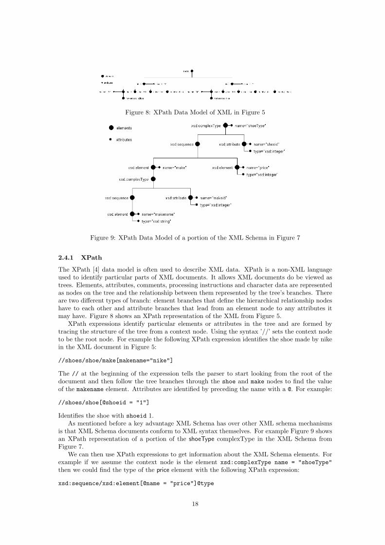
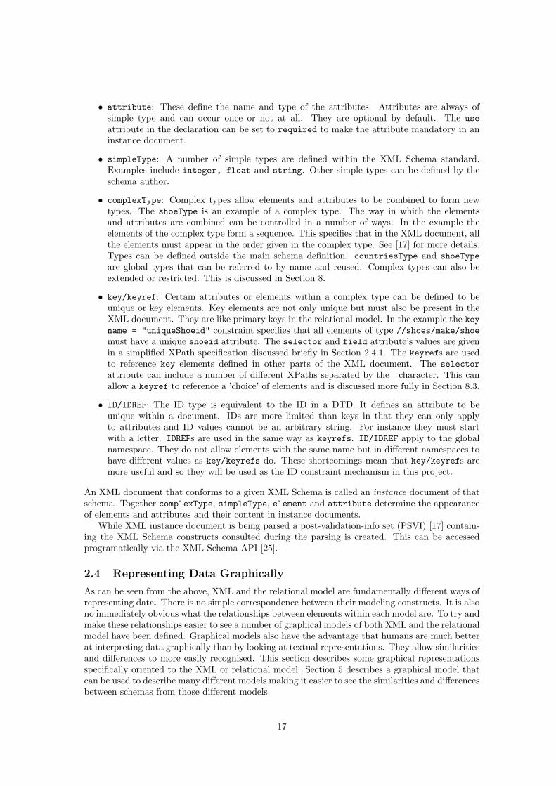
Figure 8: XPath Data Model of XML in Figure 5
Figure 9: XPath Data Model of a portion of the XML Schema in Figure 7
2.4.1 XPath
The XPath [4] data model is often used to describe XML data. XPath is a non-XML languageused to identify particular parts of XML documents. It allows XML documents do be viewed astrees. Elements, attributes, comments, processing instructions and character data are representedas nodes on the tree and the relationship between them represented by the tree’s branches. Thereare two different types of branch: element branches that define the hierarchical relationship nodeshave to each other and attribute branches that lead from an element node to any attributes itmay have. Figure 8 shows an XPath representation of the XML from Figure 5.
XPath expressions identify particular elements or attributes in the tree and are formed bytracing the structure of the tree from a context node. Using the syntax ’//’ sets the context nodeto be the root node. For example the following XPath expression identifies the shoe made by nikein the XML document in Figure 5:
//shoes/shoe/make[makename="nike"]
The // at the beginning of the expression tells the parser to start looking from the root of thedocument and then follow the tree branches through the shoe and make nodes to find the valueof the makename element. Attributes are identified by preceding the name with a @. For example:
//shoes/shoe[@shoeid = "1"]
Identifies the shoe with shoeid 1.As mentioned before a key advantage XML Schema has over other XML schema mechanisms
is that XML Schema documents conform to XML syntax themselves. For example Figure 9 showsan XPath representation of a portion of the shoeType complexType in the XML Schema fromFigure 7.
We can then use XPath expressions to get information about the XML Schema elements. Forexample if we assume the context node is the element xsd:complexType name = "shoeType"then we could find the type of the price element with the following XPath expression:
xsd:sequence/xsd:element[@name = "price"]@type
18
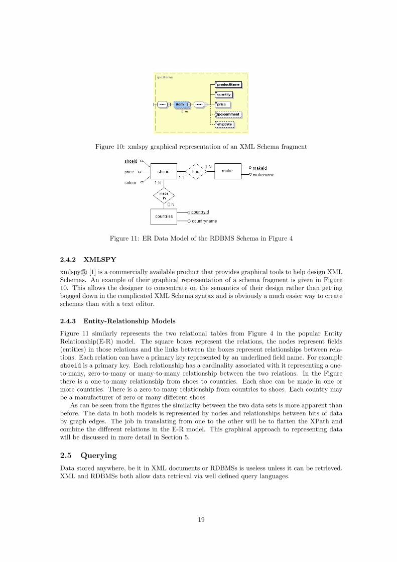
Figure 10: xmlspy graphical representation of an XML Schema fragment
Figure 11: ER Data Model of the RDBMS Schema in Figure 4
2.4.2 XMLSPY
xmlspy r© [1] is a commercially available product that provides graphical tools to help design XMLSchemas. An example of their graphical representation of a schema fragment is given in Figure10. This allows the designer to concentrate on the semantics of their design rather than gettingbogged down in the complicated XML Schema syntax and is obviously a much easier way to createschemas than with a text editor.
2.4.3 Entity-Relationship Models
Figure 11 similarly represents the two relational tables from Figure 4 in the popular EntityRelationship(E-R) model. The square boxes represent the relations, the nodes represent fields(entities) in those relations and the links between the boxes represent relationships between rela-tions. Each relation can have a primary key represented by an underlined field name. For exampleshoeid is a primary key. Each relationship has a cardinality associated with it representing a one-to-many, zero-to-many or many-to-many relationship between the two relations. In the Figurethere is a one-to-many relationship from shoes to countries. Each shoe can be made in one ormore countries. There is a zero-to-many relationship from countries to shoes. Each country maybe a manufacturer of zero or many different shoes.
As can be seen from the figures the similarity between the two data sets is more apparent thanbefore. The data in both models is represented by nodes and relationships between bits of databy graph edges. The job in translating from one to the other will be to flatten the XPath andcombine the different relations in the E-R model. This graphical approach to representing datawill be discussed in more detail in Section 5.
2.5 Querying
Data stored anywhere, be it in XML documents or RDBMSs is useless unless it can be retrieved.XML and RDBMSs both allow data retrieval via well defined query languages.
19
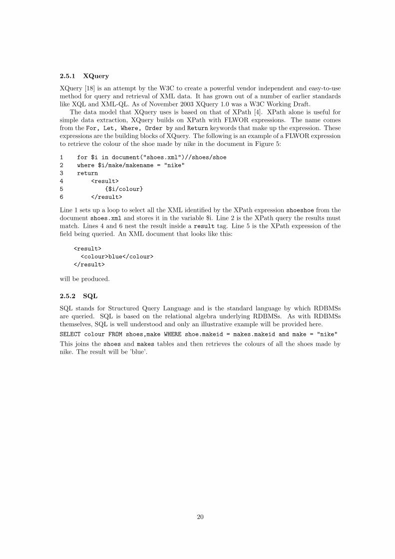
2.5.1 XQuery
XQuery [18] is an attempt by the W3C to create a powerful vendor independent and easy-to-usemethod for query and retrieval of XML data. It has grown out of a number of earlier standardslike XQL and XML-QL. As of November 2003 XQuery 1.0 was a W3C Working Draft.
The data model that XQuery uses is based on that of XPath [4]. XPath alone is useful forsimple data extraction, XQuery builds on XPath with FLWOR expressions. The name comesfrom the For, Let, Where, Order by and Return keywords that make up the expression. Theseexpressions are the building blocks of XQuery. The following is an example of a FLWOR expressionto retrieve the colour of the shoe made by nike in the document in Figure 5:
1 for $i in document("shoes.xml")//shoes/shoe2 where $i/make/makename = "nike"3 return4 <result>5 {$i/colour}6 </result>
Line 1 sets up a loop to select all the XML identified by the XPath expression shoeshoe from thedocument shoes.xml and stores it in the variable $i. Line 2 is the XPath query the results mustmatch. Lines 4 and 6 nest the result inside a result tag. Line 5 is the XPath expression of thefield being queried. An XML document that looks like this:
<result><colour>blue</colour>
</result>
will be produced.
2.5.2 SQL
SQL stands for Structured Query Language and is the standard language by which RDBMSsare queried. SQL is based on the relational algebra underlying RDBMSs. As with RDBMSsthemselves, SQL is well understood and only an illustrative example will be provided here.SELECT colour FROM shoes,make WHERE shoe.makeid = makes.makeid and make = "nike"
This joins the shoes and makes tables and then retrieves the colours of all the shoes made bynike. The result will be ’blue’.
20
3 Moving Data between RDBMSs and XML
We start this section by discussing the structural differences between XML and relational databases.There follows a brief description of the translation process and how current systems perform thisprocess.
3.1 XML/Relational Schemas
Both XML and relational data may be constrained by schemas. In XML this schema is optionalwhereas in RDBMSs it is an inherent part of the database. The XML schema may be storedwithin the document or as a separate file. The relational DDL statements that create a databaseand thereby its schema must be issued before any data can be stored in it. This schema then actsas a mandatory check on the validity of tuples before they are inserted. To be of most use, anXML schema should also be created first, and any XML documents created should be validatedagainst it. It is important to note that in XML this process is not mandatory.
3.1.1 Differences between XML and relational schemas
The data models provided by RDBMSs and XML are fundamentally different as can be seen fromthe two schemas in Figures 4 and 7. This makes translation between the two difficult.
An important difference between the XML and relational data schemas is XML’s support fornesting. Element types are allowed to contain other element types as is the case in the examplein Figure 7 where make is a subtype of shoe. These can be used to build arbitrarily deep part-ofhierarchies. It is required that all component element types are rooted in a single element type.This is in contrast to RDBMSs, which are essentially flat.
Associated with nesting comes the notion of order. Unlike relations and tuples in RDBMSs, theelement types and elements of an XML document adhere to both an explicit and implicit order.The order can be explicitly specified in the XML schema or implicitly at the XML document levelwhere the order of data elements is defined by their position in the document. This ordering maybe of semantic importance.
As XML Schema asserts itself as the dominant schema language for XML it brings specificproblems to the translation process due to its semantic richness. On top of nesting and orderingXML Schema introduces the concept of complex types and other structures that are difficult to mapdirectly to relational structures. It also greatly increases the number of ways a relational schemamay be expressed in XML leading to questions of what the ’best’ representation is. Addressingthese differences is a very important part of the translation process.
3.2 The Translation Process
There are 3 main aspects to the translation process:
1. Creation of a relational schema from a given XML schema or an XML schema from a givenrelational schema.
2. Deciding whether the schema that has been created is the most appropriate one or giving ahuman expert the chance to influence the creation of the schema. This is most importantwhen creating an XML schema as the possibilities are numerous.
3. Providing a way of querying the data held in one format using the query language of theother format or moving the data from one format to the other.
Problem 1 is of great importance to the process. Without a precise description of the destinationthe data is to go to, problem 3 becomes very difficult. Well established techniques exist to translatea given XML schema into a relational one [14] but creating an XML schema from a relationalschema is a relatively new field. Until recently systems that exported relational data as XML likeSilkroute [21] assumed that such a schema existed before the export process began. The automatic
21
creation of an XML schema from a relational one is an important task and will be investigatedin depth in Section 7. Two newer approaches provide ways of generating the schemas from theRDBMS schema [5, 3].
Problem 2 stems from the differences between the relational and semi structured XML models.There is no obvious one-to-one mapping from structures in the relational model to XML and soapproximations must be made. These can be done in a number of ways some more appropriateto a given task than others. Bohannon et al. describe an automatic approach in [14], discussedbriefly in Section 3.5.1, while a more user directed approach is adopted by L.Popa et al.[11].
If a relational database is simply being used as a place to store XML documents and we haveaccess to that RDBMS then the data can be queried directly using SQL. If we do not and thequeries need to be done on the original XML then a way of translating them into SQL is needed.XML views of the underlying relational data are a popular way of doing this and are the approachtaken in [10]. If, on the other hand, relational data is being exposed via XML two main approacheshave been adopted to accessing it. The first also uses XML views. The relational data is theneither exported into an XML document based on these views and queries issued on the XMLdocument itself or the queries are issued on the views and then translated [9]. The second adoptedin [3] creates an XML Schema representation of the relational schema. Queries are then issuedagainst that. Section 3.6 will discuss these approaches in more detail.
3.3 Main problems
The differences between XML data and that stored in RDBMSs means that moving data from oneformat to the other poses some significant problems. The first is capturing the complexity of XMLSchema in the semantically simpler relational model and the second is trying to create an efficientand appropriate representation of a relational schema in XML Schema that takes advantage of thethe latter’s flexibility.
The following are some of the issues that need to be addressed when moving data from XMLto the relational model. The first three deal with trying to maintain the structure of the XMLdocument. The final point must be addressed so that the created relations have data integrity:
1. How to model flat XML data.
2. How to model nested XML data.
3. How to maintain the order of the XML elements.
4. How to make sure that the resulting relations have a suitable candidate key.
XML can be used for a very wide variety of tasks. This report concentrates on the aspects of XMLthat are most closely related to data storage, i.e. elements, attributes and the way they are nestedtogether. My model does not support mixed content and white space in an XML document andprocessing instructions that do not relate to the XML Schema used to validate the document areignored. Ways of handling these could be introduced into the model in future.When moving data from the relational model to XML the following must be taken into account:
1. How to model relations and attributes.
2. How to model primary keys and foreign keys.
3. How will the resulting XML data be nested.
3.4 Existing Approaches
Nearly all current systems that translate between XML and RDBMSs fall into two distinct groups:
• Systems that use relational databases as a way of storing XML data, thereby taking advan-tage of the power of RDBMSs.
• Systems that use XML as a way of exporting relational data to the Internet.
22
3.4.1 Storing XML in relational databases
Existing relational databases have many powerful tools to manipulate, store and retrieve data.Storing XML in these relational systems means consumers of the data are able to take advantageof these tools to store and query the XML. There are a number of different ways of storing theXML in an RDBMS. Each method had advantages and disadvantages.
The most straightforward approach is to store XML documents as a whole within a singledatabase attribute (BLOBs or CLOBs). An advantage of this method is any XML documentcan be stored, including documents without an XML schema. The disadvantage is that the datacannot be queried and none of the structure of the XML document is preserved.
Any method for storing XML in a relational database that does not store the documents as asingle entity must have at least two steps. The first is to create a relational schema to store theXML in and and the second is to shred the XML document to capture the data from it and storethat data in the created schema. There are two main ways this has been done. They are calledthe edge schema and the element schema.
In the edge schema proposed by Florescu and Kossman in [22], the whole XML tree is storedin a fixed relational schema that records details of nodes and edges in a way that is generic to allXML data. Because the schema is fixed it is not necessary to have an XML schema file describingthe data. Figure 12 shows the XML from Figure 5 represented as an edge schema. Each elementand attribute is assigned a unique id, a parent id, an order, a type, a name and a value. The iduniquely identifies each node in the XML tree. The parent id identifies the parent node and theorder identifies the position of the node in its branch of the tree. Name is the name of the elementor attribute and value is its value. Type identifies the node as an element or attribute.
With reference to the problems mentioned in Section 3.3, flat and nested data are dealt within the same way, id provides the candidate key and the order is preserved by the ord column.
As with the previous method, any XML document can be stored in this way, in addition datafrom the document can be searched up to a point. Unfortunately queries over this schema canquickly become cumbersome or even intractable if there is a high degree of nesting in the originalXML document. For example the SQL to get the colour of the ’nike’ shoe would be as follows:
SELECT e3.value FROM edge_schema e1,edge_schema e2,edge_schema e3WHERE e1.name=’makename’ AND e1.value=’nike’ ANDe1.pid = e2.id ANDe2.pid = e3.pid AND e3.name = ’colour’;
The complexity of the above query on a relatively simple XML document shows that thismethod is not a good way to store a very large, deeply nested XML document.
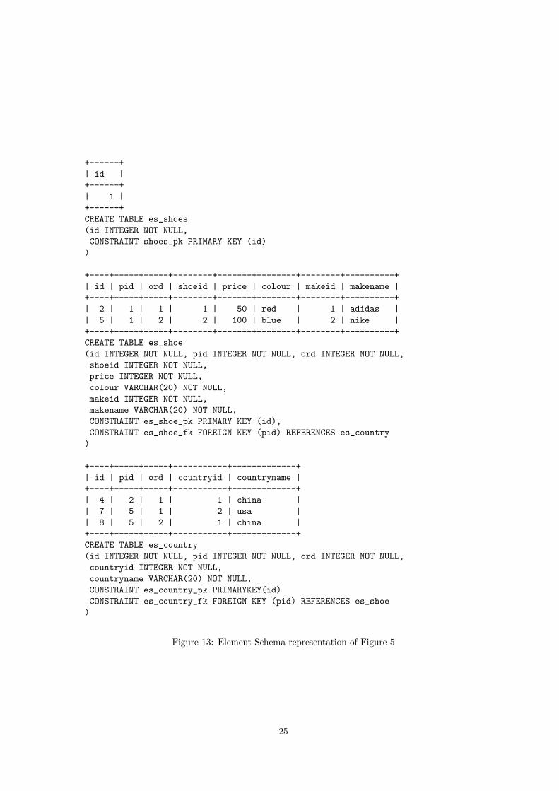
The element schema proposed by Shanmugasundaram et al. in [8] overcomes some of theproblems of storing all the XML data in a single relational table by providing a one to onemapping between multi-valued XML elements and relational tables. This method requires anXML schema describing the XML. Each potentially multi-valued schema element is representedas a new relational table. In [8] Shanmugasundaram et al. use DTD as their schema language.Any * or + element definition becomes a table. This method can be extended if the schema isdescribed by an XML Schema document. This is the approach I have adopted and is described indetail in Section 7.1.
In common with the edge schema each table has an id, a pid and an ord. These have the samemeaning as in the edge schema. The other fields in the element schema are the names of childattributes or single-valued child elements. The nesting of elements is represented as foreign keyassociations from the id of a child element to the pid of its parent element. The element schemarepresentation of the XML in Figure 5 is shown in Figure 13 as well as the SQL DDL used tocreate the tables.
The nesting of the unbounded element country inside shoe is represented by the es country fkforeign key constraint on the es country table. As with the previous method the id column isadded as a candidate key and the order of elements is recorded in the ord column.
23

+----+-----+-----+-----------+----------+---------+| id | pid | ord | type | name | value |+----+-----+-----+-----------+----------+---------+| 1 | 0 | 0 | element | shoes | NULL || 2 | 1 | 1 | element | shoe | NULL || 3 | 2 | 1 | attribute | shoeid | 1 || 4 | 2 | 1 | element | make | NULL || 5 | 4 | 1 | attribute | makeid | m1 || 6 | 4 | 1 | element | makename | adidas || 7 | 2 | 2 | element | price | 50 || 8 | 2 | 3 | element | colour | red || 9 | 2 | 4 | element | country | china || 10 | 1 | 2 | element | shoe | NULL || 11 | 10 | 1 | attribute | shoeid | 2 || 12 | 10 | 1 | element | make | NULL || 13 | 12 | 1 | attribute | makeid | m2 || 14 | 12 | 1 | element | makename | nike || 15 | 10 | 2 | element | price | 100 || 16 | 10 | 3 | element | colour | blue || 17 | 10 | 4 | element | country | usa || 18 | 10 | 5 | element | country | china |+----+-----+-----+-----------+----------+---------+
Figure 12: Edge Schema representation of the XML from Figure 5
As can be seen the use of the XML schema to help create the RDBMS schema has resultedin something must closer to the relational schema in Figure 4. Querying this schema is also fareasier than the edge schema.
SELECT es_shoe.colour FROM es_shoe, es_makeWHERE es_make.pid = es_shoe.id AND es_make.makename = ’nike’
Generating this schema is more complicated than the simple edge schema but something ofthis nature is essential for large, deeply nested XML documents.
Each of the methods described above represents the XPath tree in Figure 7 at a differentlevel of detail. Storing the whole document in a CLOB takes the XPath tree as a whole andstores it. The edge schema flattens the XPath into a single table. The element schema convertseach non-leaf node into a relational table. This shows the power of more abstract representations.Three different ways of looking at the XPath tree have resulted in three different relational schemarepresentations. These would not have been so obvious from simply looking at the XML Schemaand certainly not from the XML itself. This suggests that a graphical representation of the XMLschema may be the most useful way of representing an XML document that we wish to convertto a different data model.
3.4.2 Exporting relational data to XML
In many cases we are not interested in converting a whole database into XML, what we reallywant are selected bits of data, i.e. the results of queries.
Silkroute [21] was one of the first systems that allowed a general and efficient way to exportrelational data to XML. It defined an intermediate declarative query language called RXL toexpress the general transformations from the relational store to the XML view.
Data is exported from the relational system in two steps. First a virtual XML view of therelational data is created in RXL. Then the consumer application queries this view using XML-QL to extract the data in XML format.
24
+------+| id |+------+| 1 |+------+CREATE TABLE es_shoes(id INTEGER NOT NULL,CONSTRAINT shoes_pk PRIMARY KEY (id))
+----+-----+-----+--------+-------+--------+--------+----------+| id | pid | ord | shoeid | price | colour | makeid | makename |+----+-----+-----+--------+-------+--------+--------+----------+| 2 | 1 | 1 | 1 | 50 | red | 1 | adidas || 5 | 1 | 2 | 2 | 100 | blue | 2 | nike |+----+-----+-----+--------+-------+--------+--------+----------+CREATE TABLE es_shoe(id INTEGER NOT NULL, pid INTEGER NOT NULL, ord INTEGER NOT NULL,shoeid INTEGER NOT NULL,price INTEGER NOT NULL,colour VARCHAR(20) NOT NULL,makeid INTEGER NOT NULL,makename VARCHAR(20) NOT NULL,CONSTRAINT es_shoe_pk PRIMARY KEY (id),CONSTRAINT es_shoe_fk FOREIGN KEY (pid) REFERENCES es_country)
+----+-----+-----+-----------+-------------+| id | pid | ord | countryid | countryname |+----+-----+-----+-----------+-------------+| 4 | 2 | 1 | 1 | china || 7 | 5 | 1 | 2 | usa || 8 | 5 | 2 | 1 | china |+----+-----+-----+-----------+-------------+CREATE TABLE es_country(id INTEGER NOT NULL, pid INTEGER NOT NULL, ord INTEGER NOT NULL,countryid INTEGER NOT NULL,countryname VARCHAR(20) NOT NULL,CONSTRAINT es_country_pk PRIMARYKEY(id)CONSTRAINT es_country_fk FOREIGN KEY (pid) REFERENCES es_shoe)
Figure 13: Element Schema representation of Figure 5
25
SELECT XMLElement("COLOUR-TAG",colour) FROM shoesWHERE price = 50;
<COLOUR-TAG>red<\COLOUR-TAG>
Figure 14: SQL/XML query and result
Once the virtual view of the relational data has been constructed and the XML-QL queryformulated, the two queries are composed. The result of the composition is another RXL querythat extracts only the necessary data from the relational database.
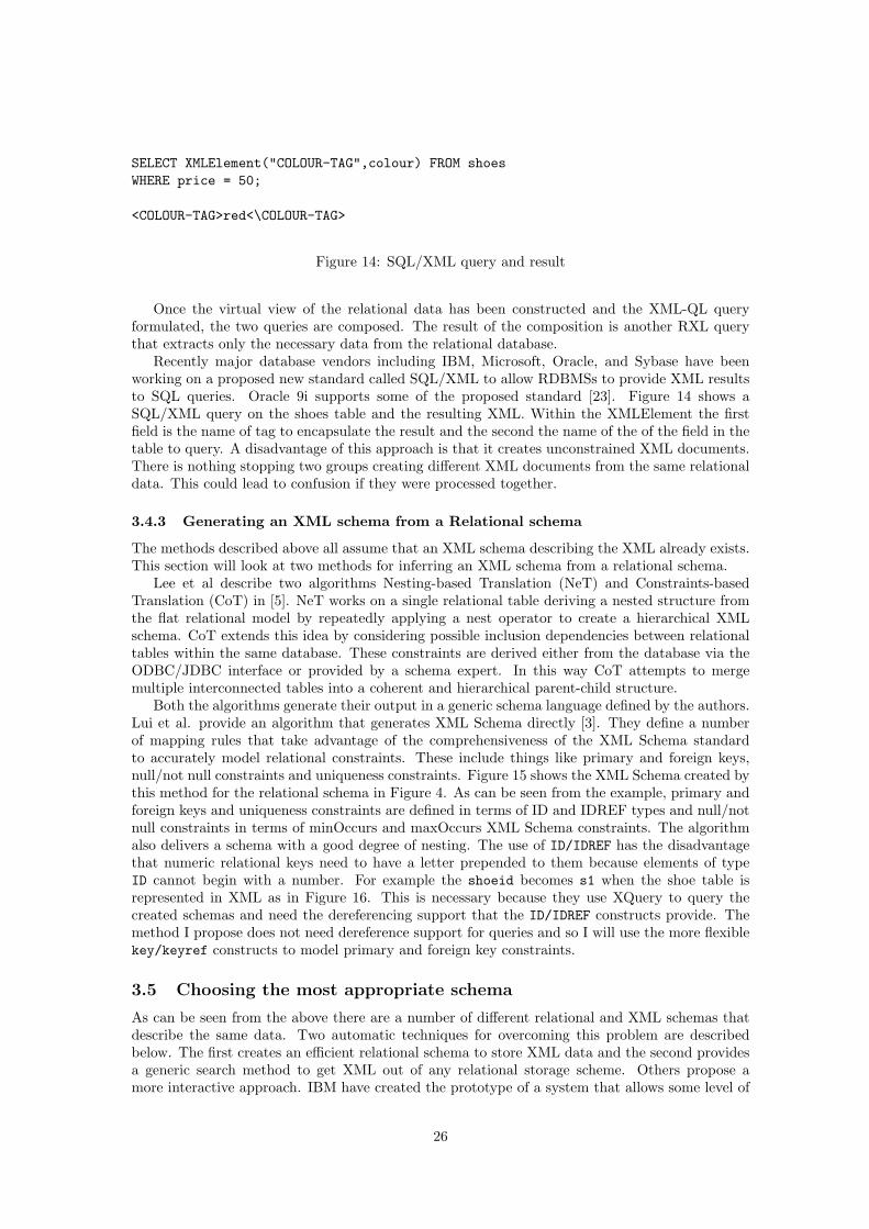
Recently major database vendors including IBM, Microsoft, Oracle, and Sybase have beenworking on a proposed new standard called SQL/XML to allow RDBMSs to provide XML resultsto SQL queries. Oracle 9i supports some of the proposed standard [23]. Figure 14 shows aSQL/XML query on the shoes table and the resulting XML. Within the XMLElement the firstfield is the name of tag to encapsulate the result and the second the name of the of the field in thetable to query. A disadvantage of this approach is that it creates unconstrained XML documents.There is nothing stopping two groups creating different XML documents from the same relationaldata. This could lead to confusion if they were processed together.
3.4.3 Generating an XML schema from a Relational schema
The methods described above all assume that an XML schema describing the XML already exists.This section will look at two methods for inferring an XML schema from a relational schema.
Lee et al describe two algorithms Nesting-based Translation (NeT) and Constraints-basedTranslation (CoT) in [5]. NeT works on a single relational table deriving a nested structure fromthe flat relational model by repeatedly applying a nest operator to create a hierarchical XMLschema. CoT extends this idea by considering possible inclusion dependencies between relationaltables within the same database. These constraints are derived either from the database via theODBC/JDBC interface or provided by a schema expert. In this way CoT attempts to mergemultiple interconnected tables into a coherent and hierarchical parent-child structure.
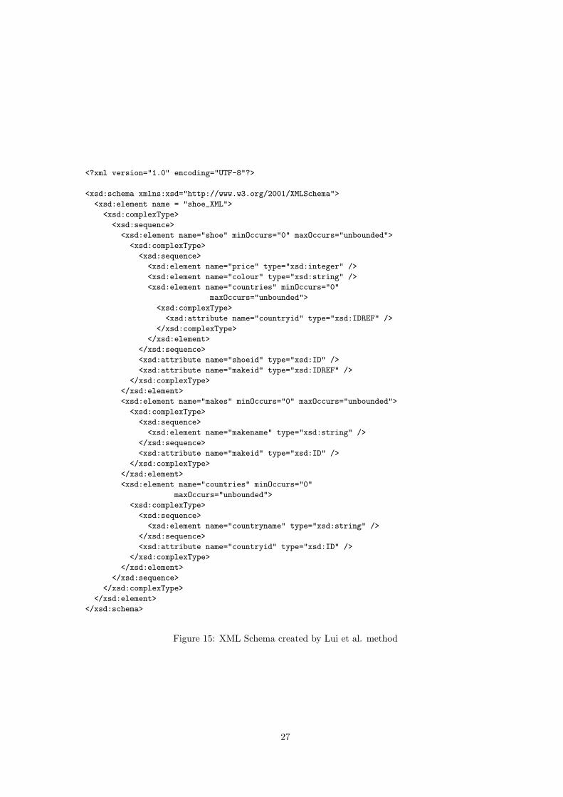
Both the algorithms generate their output in a generic schema language defined by the authors.Lui et al. provide an algorithm that generates XML Schema directly [3]. They define a numberof mapping rules that take advantage of the comprehensiveness of the XML Schema standardto accurately model relational constraints. These include things like primary and foreign keys,null/not null constraints and uniqueness constraints. Figure 15 shows the XML Schema created bythis method for the relational schema in Figure 4. As can be seen from the example, primary andforeign keys and uniqueness constraints are defined in terms of ID and IDREF types and null/notnull constraints in terms of minOccurs and maxOccurs XML Schema constraints. The algorithmalso delivers a schema with a good degree of nesting. The use of ID/IDREF has the disadvantagethat numeric relational keys need to have a letter prepended to them because elements of typeID cannot begin with a number. For example the shoeid becomes s1 when the shoe table isrepresented in XML as in Figure 16. This is necessary because they use XQuery to query thecreated schemas and need the dereferencing support that the ID/IDREF constructs provide. Themethod I propose does not need dereference support for queries and so I will use the more flexiblekey/keyref constructs to model primary and foreign key constraints.
3.5 Choosing the most appropriate schema
As can be seen from the above there are a number of different relational and XML schemas thatdescribe the same data. Two automatic techniques for overcoming this problem are describedbelow. The first creates an efficient relational schema to store XML data and the second providesa generic search method to get XML out of any relational storage scheme. Others propose amore interactive approach. IBM have created the prototype of a system that allows some level of
26
<?xml version="1.0" encoding="UTF-8"?>
<xsd:schema xmlns:xsd="http://www.w3.org/2001/XMLSchema">
<xsd:element name = "shoe_XML">
<xsd:complexType>
<xsd:sequence>
<xsd:element name="shoe" minOccurs="0" maxOccurs="unbounded">
<xsd:complexType>
<xsd:sequence>
<xsd:element name="price" type="xsd:integer" />
<xsd:element name="colour" type="xsd:string" />
<xsd:element name="countries" minOccurs="0"
maxOccurs="unbounded">
<xsd:complexType>
<xsd:attribute name="countryid" type="xsd:IDREF" />
</xsd:complexType>
</xsd:element>
</xsd:sequence>
<xsd:attribute name="shoeid" type="xsd:ID" />
<xsd:attribute name="makeid" type="xsd:IDREF" />
</xsd:complexType>
</xsd:element>
<xsd:element name="makes" minOccurs="0" maxOccurs="unbounded">
<xsd:complexType>
<xsd:sequence>
<xsd:element name="makename" type="xsd:string" />
</xsd:sequence>
<xsd:attribute name="makeid" type="xsd:ID" />
</xsd:complexType>
</xsd:element>
<xsd:element name="countries" minOccurs="0"
maxOccurs="unbounded">
<xsd:complexType>
<xsd:sequence>
<xsd:element name="countryname" type="xsd:string" />
</xsd:sequence>
<xsd:attribute name="countryid" type="xsd:ID" />
</xsd:complexType>
</xsd:element>
</xsd:sequence>
</xsd:complexType>
</xsd:element>
</xsd:schema>
Figure 15: XML Schema created by Lui et al. method
27

<?xml version="1.0" encoding="UTF-8"?>
<shoe_XML xmlns:xsi=’http://www.w3.org/2001/XMLSchema-instance’xsi:noNamespaceSchemaLocation=’file:sch_shoes.xsd’><shoe shoeid="s1" makeid="m1"><price>50</price><colour>red</colour><countries countryid="c1" />
</shoe><shoe shoeid="s2" makeid="m2"><price>100</price><colour>blue</colour><countries countryid="c2" /><countries countryid="c1" />
</shoe>
<makes makeid="m1"><makename>adidas</makename>
</makes><makes makeid="m2"><makename>nike</makename>
</makes><countries countryid="c1"><countryname>china</countryname>
</countries><countries countryid="c2"><countryname>usa</countryname>
</countries></shoe_XML>
Figure 16: XML conforming to the XML Schema in Figure 15
28
user interaction in the choice of schema mappings [11]. The Net and CoT algorithms describedabove also suggest the participation of a human expert to help the system create the best possibleschema.
3.5.1 LegoDB
LegoDB is primarily concerned with storing XML in a relational database in the most efficientmanner. It creates a number of possible relational schemas based on a given XML Schema andchooses the most efficient via a cost-based approach. The method relies on the fact that manydifferent XML Schemas can describe exactly the same set of documents and that these differentXML Schemas may result in relational schemas that differ widely in the performance they canoffer. The authors note that the possible number of these different schemas is very large, possibleeven infinite, so they define an algorithm to limit the number created.
Given an XML Schema the technique transforms it into a number of other different but seman-tically equivalent schemas. The schemas are presented in a modified schema language P-schemathat adds statistics about the underlying XML data for later performance analysis. They makeuse of XML Query Algebra that abstracts away some of the more complex feature of XML-Schema. The transforms are done at the XML Schema level rather that the relational becauseXML Schema is semantically far richer and can express complex constraints that would be verydifficult to express in a relational context with relative ease.
3.6 Querying the data
Data can be extracted from an relational database and expressed as XML in a number of ways.If we have direct access to the relational database and know the schema we want to query wecould use SQL/XML [23]. If, however, we want to generate queries on the XML there are variousoptions. Firstly we could move all the data from the relational database into one or a numberof XML documents and then query those directly. This is time-consuming but may be necessaryif the original relational database is not available. For example the data needs to be sent to acustomer who has no access to the sellers RDBMS. If the relational database is available XMLviews of the underlying relational data can be created and queries made on those views. Thesequeries are then translated into the corresponding SQL queries that are then executed on theRDBMS. This is the approach taken by SilkRoute [21] and XPERANTO [12].
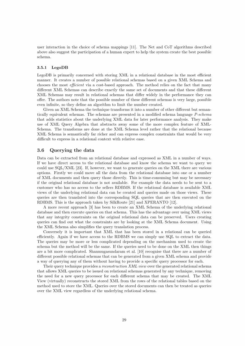
A more recent approach [3] has been to create an XML Schema of the underlying relationaldatabase and then execute queries on that schema. This has the advantage over using XML viewsthat any integrity constraints on the original relational data can be preserved. Users creatingqueries can find out what the constraints are by looking at the XML Schema document. Usingthe XML Schema also simplifies the query translation process.
Conversely it is important that XML that has been stored in a relational can be queriedefficiently. Again if we have access to the RDBMS we can simply use SQL to extract the data.The queries may be more or less complicated depending on the mechanism used to create theschema but the method will be the same. If the queries need to be done on the XML then thingsare a bit more complicated. Shanmugasundaram et al. [10] recognise that there are a number ofdifferent possible relational schemas that can be generated from a given XML schema and providea way of querying any of them without having to provide a specific query processor for each.
Their query technique provides a reconstruction XML view over the generated relational schemathat allows XML queries to be issued on relational schemas generated by any technique, removingthe need for a new query processor for each different schema that may be created. The XMLView (virtually) reconstructs the stored XML from the rows of the relational tables based on themethod used to store the XML. Queries over the stored documents can then be treated as queriesover the XML view regardless of the underlying relational schema.
29
4 An Approach to the Translation Using Graphical Tech-niques
A system that translates between XML and RDBMSs needs to have the following features:
1. A way to create a relational schema from a given XML document or XML Schema.
2. A way to create an XML schema from a given relational schema.
3. A method for deciding whether the schema that has been created is the most appropriateone or giving a human expert the chance to influence the creation of the schema.
4. A way of querying the data in either format or moving it from one format to the other.
5. A graphical way of describing each schema independently of its model would make it eas-ier to see any correspondences that may exist as humans are much better at interpretinginformation graphically than textually. Section 6.1 provides a number of examples of this.
The following sections will describe a system that has all of the above features and how the variousdifficulties associated with them are overcome.
4.1 XML to Relational
As noted previously it is possible for an XML document to have no schema describing it. This,however, can lead to XML documents with the same information in them having different struc-tures. Documents such as these could be stored in a relational database using Florescu andKossman’s method described in [22]. As stated above, using this method makes getting at thedata again is difficult. To get an accurate and efficient transformation a schema is required. Forthe rest of this report I will assume that XML documents I wish to transform are constrained byan XML Schema document.
When an XML document constrained by an XML Schema is parsed, the post schema validationinfo set (PSVI) contains the XML Schema structures. These are used to create the relationalschema. A method similar to the element schema proposed by Shanmugasundaram et al. isadopted. The use of XML Schema as the schema language rather than DTDs potentially greatlyimproves the quality of the relational schema produced. For example if any key constructs existin the XML Schema these can be used as candidate keys in the relational schema removing theneed the id field used in the element schema.
The following are some general rules about how XML Schema constructs will be transformedinto relational constructs:
• XML Schema complexTypes will be transformed into relations.
• XML Schema attributes and elements that are of a simple type within a given complextype will become attributes in the corresponding relation. Any elements with a minOccursof 0 will be make null-able. Elements with a maxOccurs of unbounded will generate relations.
• XML Schema key constraints on a given complex type will become primary keys on thecorresponding relation.
• Single value XML Schema keyref constraints on a given complex type will become foreignkeys on the corresponding relation. Transforming keyrefs and keys that contain a choicein the XPath of their selector attribute is discussed in Section 8.3.
• XML Schema elements within a complex type that are of a complex type themselves willgenerate a link relation between the two relations generated by the enclosing complex typeand the complex type of the element.
Section 7.1 describes this process in detail and a number of special cases are discussed in Section8.
30
4.2 Relational to XML Schema
The algorithm for creating an XML schema from a relational schema is based on that proposedby Lui et al [3]. Again XML Schema is used as the schema language. My query method does notuse any query languages that rely on the dereferencing capability of the ID/IDREF constructs soI’m able to use the more flexible key/keyref to define primary and foreign key constraints.
The following are some general rules about how relational constructs will be transformed intoXML Schema:
• Relations will become XML Schema complexTypes.
• Non-key attributes within a relation will become elements of simple type within the corre-sponding complex type. If they are null-able the occurrence constraint minOccurs will beset to 0.
• Primary key attributes will become XML Schema attributes within the correspondingcomplex type and an XML Schema key identity constraint will be created.
• Foreign key attributes will become XML Schema attributes within the corresponding com-plex type and an XML Schema keyref identity constraint will be created.
• A GUI will be provided to allow the user to influence the way the resulting XML Schemawill be nested.
Section 7.1 describes this process in detail and a number of special cases are discussed in Section8.
4.3 The Appropriateness of the Schema
Creating an appropriate XML schema for a given relational data set may depend on things thatwere not known when the translation algorithm was written. For this reason I have created aGUI tool that allows a schema expert to design the XML Schema they think best, from the givenrelational schema. Any number of different schemas may be created. The tool will check thevalidity of each one and will not allow illegal transformations. The tool will be discussed in detailin Section 9
4.4 Querying the Schema
All transformations of data and schemas are done within the Automed framework [2] using theHDM as a Common Data Model(CDM). The IQL [31] query language within Automed allowsall the data in the relational database to be moved to XML or queries can then be run on theAutomed XML Schema that will be translated to queries on the relational database itself.
4.5 An Abstract Data Model
A way of defining the semantics of each model’s constructs independently of their data modelswould help to ease translation between them. Section 2.4 presented two graphical languagesthat go some way to abstracting away the differences. However, they were designed as high-levellanguages for a specific model and cannot be used to represent constructs in a different model.For example there is no way to represent nesting or order in the E-R model. What is needed is aunifying lower-level language in terms of which constructs, transformations and inter-model linksfor both modeling languages can be defined. The HDM described in the next section is one suchmodel. The Automed editor [26] provides a way of showing the relationships between the variouscomponents of a schema.
Figure 17 shows a screen shot from the Automed editor with an HDM representation of aschema on the left, a relational one of the same schema in the middle and a XML Schema repre-sentation on the right.
31
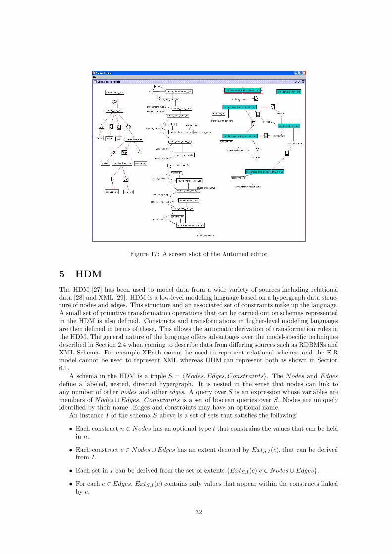
Figure 17: A screen shot of the Automed editor
5 HDM
The HDM [27] has been used to model data from a wide variety of sources including relationaldata [28] and XML [29]. HDM is a low-level modeling language based on a hypergraph data struc-ture of nodes and edges. This structure and an associated set of constraints make up the language.A small set of primitive transformation operations that can be carried out on schemas representedin the HDM is also defined. Constructs and transformations in higher-level modeling languagesare then defined in terms of these. This allows the automatic derivation of transformation rules inthe HDM. The general nature of the language offers advantages over the model-specific techniquesdescribed in Section 2.4 when coming to describe data from differing sources such as RDBMSs andXML Schema. For example XPath cannot be used to represent relational schemas and the E-Rmodel cannot be used to represent XML whereas HDM can represent both as shown in Section6.1.
A schema in the HDM is a triple S = 〈Nodes,Edges, Constraints〉. The Nodes and Edgesdefine a labeled, nested, directed hypergraph. It is nested in the sense that nodes can link toany number of other nodes and other edges. A query over S is an expression whose variables aremembers of Nodes ∪ Edges. Constraints is a set of boolean queries over S. Nodes are uniquelyidentified by their name. Edges and constraints may have an optional name.
An instance I of the schema S above is a set of sets that satisfies the following:
• Each construct n ∈ Nodes has an optional type t that constrains the values that can be heldin n.
• Each construct c ∈ Nodes∪Edges has an extent denoted by ExtS,I(c), that can be derivedfrom I.
• Each set in I can be derived from the set of extents {ExtS,I(c)|c ∈ Nodes ∪ Edges}.
• For each e ∈ Edges, ExtS,I(e) contains only values that appear within the constructs linkedby e.
32
• For each c ∈ Constraints, the query c[v1/ExtS,I(v1), ..., vn/ExtS,I(vn)] evaluates to true,where v1, ..., vn ∈ Nodes ∪ Edges are the variables of c.
The function ExtS,I is called an extension mapping. A model is a triple 〈S, I, ExtS,I〉. Twoschemas are equivalent if they have the same set of instances. Two schemas S and S′ can also beconditionally equivalent with respect to a condition f if any instance of S′ satisfying f is also aninstance of S.
The primitive transformations of the HDM are listed below. Each transformation is a functionthat when applied to a model returns a new model. Each transformation has a proviso thatstates when the transformation is successful. If a transformation is not successful it returns an’undefined’ model, denoted by ∅. Any transformation applied to ∅ returns ∅.
1. renameNode〈fromName, toName〉 renames a node. Proviso: toName is not the name ofan existing node.
2. renameEdge〈〈fromName, c1, ..., cm〉, toName〉 renames an edge. Proviso: toName is thename of an existing edge.
3. addConstraint c adds a new constraint c. Proviso: c evaluates to true.
4. delConstraint c removes constraint c. Proviso: c exists.
5. addNode(〈〈name, q〉〉) adds a node name whose extent is given by the value of the query q.name is not the name of an existing node.
6. delNode(〈〈name, q〉〉) removes a node. q is a query that states how the extent of the deletednode could be recovered from the extents of the remaining schema constructs. Proviso: thenode exists and does not participate in any edges.
7. addEdge〈〈name, c1, ..., cm〉, q〉 adds a new edge between a sequence of existing constructsc1, ...cn. q is the extent. Proviso: name is not an existing edge, c1, ..., cm exist and qsatisfied the appropriate domain constraints.
8. delEdge〈〈name, c1, ..., cm〉, q〉 deletes the edge name. q states how the deleted edge couldbe recovered from the extents of the remaining schema constructs. Proviso: the edge existsand participates in no other edges.
A transformation t is schema-dependent with respect to a schema S if t does not return ∅ for anymodel of S otherwise t is instance-dependent with respect to S. If S can be transformed in S′
they have the same set of instances and must therefore be equivalent. If a proviso f is necessaryto transform S to S′ then S and S′ are conditionally equivalent with respect to f .
Every successful transformation t is reversible by a transformation t−1. For example thetransformation addNode(〈〈n, q〉〉) can be reversed by delNode(〈〈n, q〉〉).
5.1 Higher Level Modeling Languages in HDM
In general, any semantic modeling language consists of two types of construct: extensional con-structs and constraint constructs. The scheme of a construct uniquely identifies it. Extensionalconstructs represent the set of data values in a given domain. There are three classes:
• Nodal: These may be present independently of any other constructs. They map onto nodesin the HDM.
• Linking: The extent of a linking construct is a subset of the Cartesian product of the extentsof the constructs that it links. Obviously linking constructs cannot exist in isolation. Theymap onto edges in the HDM.
• Nodal-Linking: These are nodal constructs that can only exist when certain other con-structs link to them. They are mapped to a node and an edge in the HDM
33
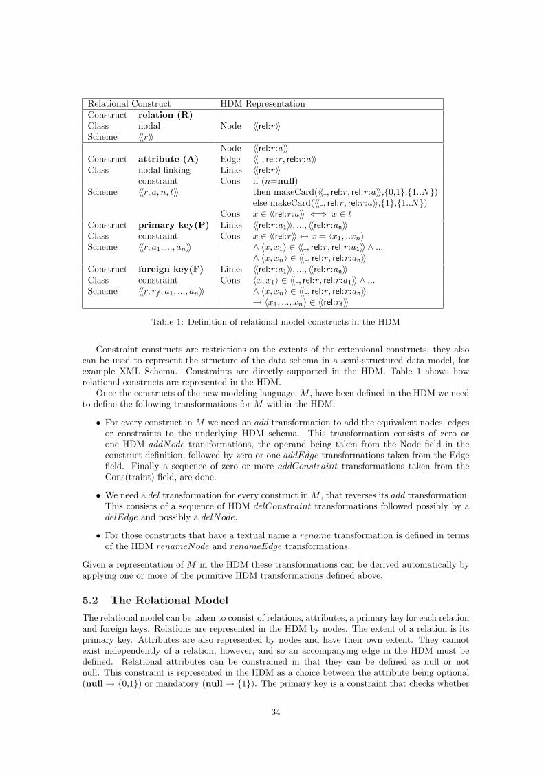
Relational Construct HDM RepresentationConstruct relation (R)Class nodal Node 〈〈rel:r〉〉Scheme 〈〈r〉〉
Node 〈〈rel:r :a〉〉Construct attribute (A) Edge 〈〈 , rel:r , rel:r :a〉〉Class nodal-linking Links 〈〈rel:r〉〉
constraint Cons if (n=null)Scheme 〈〈r, a, n, t〉〉 then makeCard(〈〈 , rel:r , rel:r :a〉〉,{0,1},{1..N})
else makeCard(〈〈 , rel:r , rel:r :a〉〉,{1},{1..N})Cons x ∈ 〈〈rel:r :a〉〉 ⇐⇒ x ∈ t
Construct primary key(P) Links 〈〈rel:r :a1〉〉, ..., 〈〈rel:r :an〉〉Class constraint Cons x ∈ 〈〈rel:r〉〉 ↔ x = 〈x1, ..xn〉Scheme 〈〈r, a1, ..., an〉〉 ∧ 〈x, x1〉 ∈ 〈〈 , rel:r , rel:r :a1〉〉 ∧ ...
∧ 〈x, xn〉 ∈ 〈〈 , rel:r , rel:r :an〉〉Construct foreign key(F) Links 〈〈rel:r :a1〉〉, ..., 〈〈rel:r :an〉〉Class constraint Cons 〈x, x1〉 ∈ 〈〈 , rel:r , rel:r :a1〉〉 ∧ ...Scheme 〈〈r, rf , a1, ..., an〉〉 ∧ 〈x, xn〉 ∈ 〈〈 , rel:r , rel:r :an〉〉
→ 〈x1, ..., xn〉 ∈ 〈〈rel:r f〉〉
Table 1: Definition of relational model constructs in the HDM
Constraint constructs are restrictions on the extents of the extensional constructs, they alsocan be used to represent the structure of the data schema in a semi-structured data model, forexample XML Schema. Constraints are directly supported in the HDM. Table 1 shows howrelational constructs are represented in the HDM.
Once the constructs of the new modeling language, M , have been defined in the HDM we needto define the following transformations for M within the HDM:
• For every construct in M we need an add transformation to add the equivalent nodes, edgesor constraints to the underlying HDM schema. This transformation consists of zero orone HDM addNode transformations, the operand being taken from the Node field in theconstruct definition, followed by zero or one addEdge transformations taken from the Edgefield. Finally a sequence of zero or more addConstraint transformations taken from theCons(traint) field, are done.
• We need a del transformation for every construct in M , that reverses its add transformation.This consists of a sequence of HDM delConstraint transformations followed possibly by adelEdge and possibly a delNode.
• For those constructs that have a textual name a rename transformation is defined in termsof the HDM renameNode and renameEdge transformations.
Given a representation of M in the HDM these transformations can be derived automatically byapplying one or more of the primitive HDM transformations defined above.
5.2 The Relational Model
The relational model can be taken to consist of relations, attributes, a primary key for each relationand foreign keys. Relations are represented in the HDM by nodes. The extent of a relation is itsprimary key. Attributes are also represented by nodes and have their own extent. They cannotexist independently of a relation, however, and so an accompanying edge in the HDM must bedefined. Relational attributes can be constrained in that they can be defined as null or notnull. This constraint is represented in the HDM as a choice between the attribute being optional(null → {0,1}) or mandatory (null → {1}). The primary key is a constraint that checks whether
34
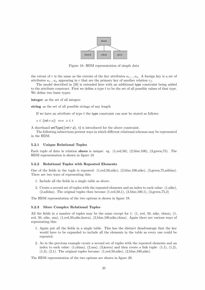
Figure 18: HDM representation of simple data
the extent of r is the same as the extents of the key attributes a1, .., an. A foreign key is a set ofattributes a1, ..an appearing in r that are the primary key of another relation rf .
The model described in [28] is extended here with an additional type constraint being addedto the attribute construct. First we define a type t to be the set of all possible values of that type.We define two basic types:
integer as the set of all integers
string as the set of all possible strings of any length
If we have an attribute of type t the type constraint can now be stated as follows:
x ∈ 〈〈rel:r :a〉〉 ⇐⇒ x ∈ t
A shorthand setType(〈〈rel:r :a〉〉, t) is introduced for the above constraint.The following subsections present ways in which different relational schemas may be represented
in the HDM.
5.2.1 Unique Relational Tuples
Each tuple of data in relation shoes is unique: eg. (1,red,50), (2,blue,100), (3,green,75). TheHDM representation is shown in figure 18
5.2.2 Relational Tuples with Repeated Elements
One of the fields in the tuple is repeated: (1,red,50,nike), (2,blue,100,nike), (3,green,75,adidas).There are two ways of representing this:
1. Include all the fields in a single table as above.
2. Create a second set of tuples with the repeated elements and an index to each value: (1,nike),(2,adidas). The original tuples then become (1,red,50,1), (2,blue,100,1), (3,green,75,2)
The HDM representation of the two options is shown in figure 19.
5.2.3 More Complex Relational Tuples
All the fields in a number of tuples may be the same except for 1: (1, red, 50, nike, china), (1,red, 50, nike, usa), (1,red,50,nike,korea), (2,blue,100,nike,china). Again there are various ways ofrepresenting this:
1. Again put all the fields in a single table. This has the distinct disadvantage that the keywould have to be expanded to include all the elements in the table as every one could berepeated.
2. As in the previous example create a second set of tuples with the repeated elements and anindex to each value: (1,china), (2,usa), (3,korea) and then create a link tuple: (1,1), (1,2),(1,3), (2,1). The original tuples become: (1,red,50,nike), (2,blue,100,nike).
The HDM representation of the two options are shown in figure 20.
35
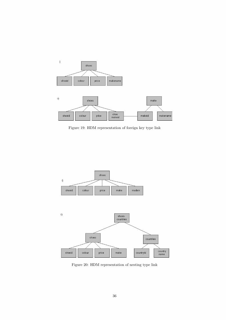
Figure 19: HDM representation of foreign key type link
Figure 20: HDM representation of nesting type link
36
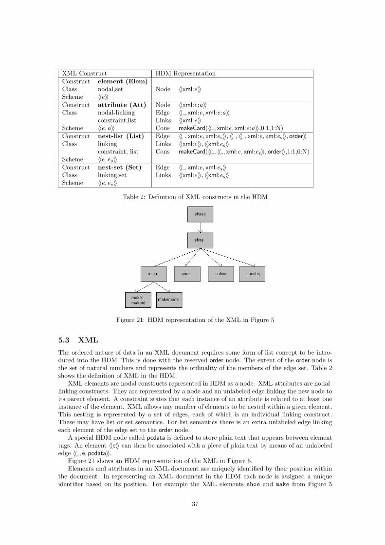
XML Construct HDM RepresentationConstruct element (Elem)Class nodal,set Node 〈〈xml:e〉〉Scheme 〈〈e〉〉Construct attribute (Att) Node 〈〈xml:e:a〉〉Class nodal-linking Edge 〈〈 , xml:e, xml:e:a〉〉
constraint,list Links 〈〈xml:e〉〉Scheme 〈〈e, a〉〉 Cons makeCard(〈〈 , xml:e, xml:e:a〉〉,0:1,1:N)Construct nest-list (List) Edge 〈〈 , xml:e, xml:es〉〉, 〈〈 , 〈〈 , xml:e, xml:es〉〉, order〉〉Class linking Links 〈〈xml:e〉〉, 〈〈xml:es〉〉
constraint, list Cons makeCard(〈〈 , 〈〈 , xml:e, xml:es〉〉, order〉〉,1:1,0:N)Scheme 〈〈e, es〉〉Construct nest-set (Set) Edge 〈〈 , xml:e, xml:es〉〉Class linking,set Links 〈〈xml:e〉〉, 〈〈xml:es〉〉Scheme 〈〈e, es〉〉
Table 2: Definition of XML constructs in the HDM
Figure 21: HDM representation of the XML in Figure 5
5.3 XML
The ordered nature of data in an XML document requires some form of list concept to be intro-duced into the HDM. This is done with the reserved order node. The extent of the order node isthe set of natural numbers and represents the ordinality of the members of the edge set. Table 2shows the definition of XML in the HDM.
XML elements are nodal constructs represented in HDM as a node. XML attributes are nodal-linking constructs. They are represented by a node and an unlabeled edge linking the new node toits parent element. A constraint states that each instance of an attribute is related to at least oneinstance of the element. XML allows any number of elements to be nested within a given element.This nesting is represented by a set of edges, each of which is an individual linking construct.These may have list or set semantics. For list semantics there is an extra unlabeled edge linkingeach element of the edge set to the order node.
A special HDM node called pcdata is defined to store plain text that appears between elementtags. An element 〈〈e〉〉 can then be associated with a piece of plain text by means of an unlabelededge 〈〈 , e, pcdata〉〉.
Figure 21 shows an HDM representation of the XML in Figure 5.Elements and attributes in an XML document are uniquely identified by their position within
the document. In representing an XML document in the HDM each node is assigned a uniqueidentifier based on its position. For example the XML elements shoe and make from Figure 5
37
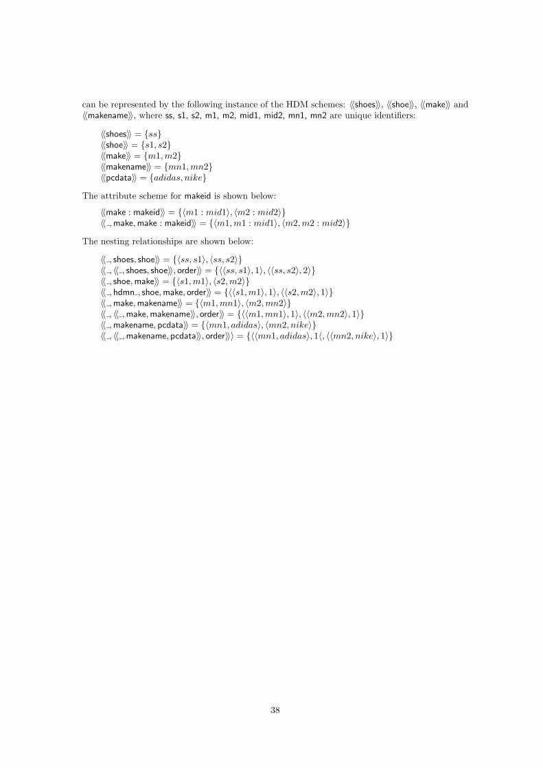
can be represented by the following instance of the HDM schemes: 〈〈shoes〉〉, 〈〈shoe〉〉, 〈〈make〉〉 and〈〈makename〉〉, where ss, s1, s2, m1, m2, mid1, mid2, mn1, mn2 are unique identifiers:
〈〈shoes〉〉 = {ss}〈〈shoe〉〉 = {s1, s2}〈〈make〉〉 = {m1,m2}〈〈makename〉〉 = {mn1,mn2}〈〈pcdata〉〉 = {adidas, nike}
The attribute scheme for makeid is shown below:
〈〈make : makeid〉〉 = {〈m1 : mid1〉, 〈m2 : mid2〉}〈〈 ,make,make : makeid〉〉 = {〈m1,m1 : mid1〉, 〈m2,m2 : mid2〉}
The nesting relationships are shown below:
〈〈 , shoes, shoe〉〉 = {〈ss, s1〉, 〈ss, s2〉}〈〈 , 〈〈 , shoes, shoe〉〉, order〉〉 = {〈〈ss, s1〉, 1〉, 〈〈ss, s2〉, 2〉}〈〈 , shoe,make〉〉 = {〈s1,m1〉, 〈s2,m2〉}〈〈 , hdmn , shoe,make, order〉〉 = {〈〈s1,m1〉, 1〉, 〈〈s2,m2〉, 1〉}〈〈 ,make,makename〉〉 = {〈m1,mn1〉, 〈m2,mn2〉}〈〈 , 〈〈 ,make,makename〉〉, order〉〉 = {〈〈m1,mn1〉, 1〉, 〈〈m2,mn2〉, 1〉}〈〈 ,makename, pcdata〉〉 = {〈mn1, adidas〉, 〈mn2, nike〉}〈〈 , 〈〈 ,makename, pcdata〉〉, order〉〉〉 = {〈〈mn1, adidas〉, 1〈, 〈〈mn2, nike〉, 1〉}
38
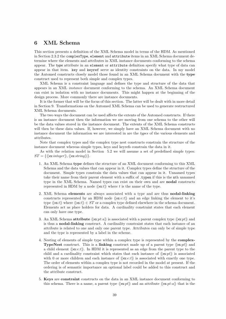
6 XML Schema
This section presents a definition of the XML Schema model in terms of the HDM. As mentionedin Section 2.3.2 the complexType, element and attribute items in an XML Schema document de-termine where the elements and attributes in XML instance documents conforming to the schemaappear. The type attribute in an element or attribute definition specify what type of data canappear in that item. key and keyref serve as identity constraints on the data. In my modelthe Automed constructs closely model those found in an XML Schema document with the typeconstruct used to represent both simple and complex types.
XML Schema is a constraint language and defines the type and structure of the data thatappears in an XML instance document conforming to the schema. An XML Schema documentcan exist in isolation with no instance documents. This might happen at the beginning of thedesign process. More commonly there are instance documents.
It is the former that will be the focus of this section. The latter will be dealt with in more detailin Section 9. Transformations on the Automed XML Schema can be used to generate restructuredXML Schema documents.
The two ways the document can be used affects the extents of the Automed constructs. If thereis an instance document then the information we are moving from one schema to the other willbe the data values stored in the instance document. The extents of the XML Schema constructswill then be these data values. If, however, we simply have an XML Schema document with noinstance document the information we are interested in are the types of the various elements andattributes.
Note that complex types and the complex type nest constructs constrain the structure of theinstance document whereas simple types, keys and keyrefs constrain the data in it.
As with the relation model in Section 5.2 we will assume a set of predefined simple types:ST = {〈〈xs:integer〉〉, 〈〈xs:string〉〉}.
1. An XML Schema type defines the structure of an XML document conforming to this XMLSchema and the data values that can appear in it. Complex types define the structure of thedocument. Simple types constrain the data values that can appear in it. Unnamed typestake their name from their parent element with a suffix of typen if this is the nth unnamedtype in the XML Schema. Named types can exist on their own and are nodal constructsrepresented in HDM by a node 〈〈xs:t〉〉 where t is the name of the type.
2. XML Schema elements are always associated with a type and are thus nodal-linkingconstructs represented by an HDM node 〈〈xs:e:t〉〉 and an edge linking the element to it’stype 〈〈xs:t〉〉 where 〈〈xs:t〉〉 ∈ ST or a complex type defined elsewhere in the schema document.Elements act as place holders for data. A cardinality constraint states that each elementcan only have one type.
3. An XML Schema attribute 〈〈xs:pt :a〉〉 is associated with a parent complex type 〈〈xs:pt〉〉 andis thus a nodal-linking construct. A cardinality constraint states that each instance of anattribute is related to one and only one parent type. Attributes can only be of simple typeand the type is represented by a label in the scheme.
4. Nesting of elements of simple type within a complex type is represented by the complex-TypeNest construct. This is a linking construct made up of a parent type 〈〈xs:pt〉〉 anda child element 〈〈xs:e:t〉〉. In HDM it is represented as an edge from the parent type to thechild and a cardinality constraint which states that each instance of 〈〈xs:pt〉〉 is associatedwith 0 or more children and each instance of 〈〈xs:e:t〉〉 is associated with exactly one type.The order of elements within a complex type is not recorded in the model at present. If theordering is of semantic importance an optional label could be added to this construct andthe attribute construct.
5. Keys are constraint constructs on the data in an XML instance document conforming tothis schema. There is a name, a parent type 〈〈xs:pt〉〉 and an attribute 〈〈xs:pt :a〉〉 that is the
39
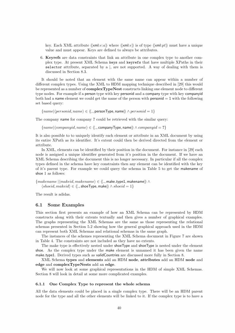
key. Each XML attribute 〈〈xml:e:a〉〉 where 〈〈xml:e〉〉 is of type 〈〈xml:pt〉〉 must have a uniquevalue and must appear. Keys are defined to always be attributes.
6. Keyrefs are data constraints that link an attribute in one complex type to another com-plex type. At present XML Schema keys and keyrefs that have multiple XPaths in theirselector attribute, separated by a |, are not supported. A way of dealing with them isdiscussed in Section 8.3.
It should be noted that an element with the same name can appear within a number ofdifferent complex types. Using the XML to HDM mapping technique described in [29] this wouldbe represented as a number of complexTypeNest constructs linking one element node to differenttype nodes. For example if a person type with key personid and a company type with key companyidboth had a name element we could get the name of the person with personid = 1 with the followingset based query:
{name|〈personid, name〉 ∈ 〈〈 , personType, name〉〉 ∧ personid = 1}
The company name for company 7 could be retrieved with the similar query:
{name|〈companyid, name〉 ∈ 〈〈 , companyType, name〉〉 ∧ companyid = 7}
It is also possible to to uniquely identify each element or attribute in an XML document by usingits entire XPath as its identifier. It’s extent could then be derived directed from the element orattribute.
In XML, elements can be identified by their position in the document. For instance in [29] eachnode is assigned a unique identifier generated from it’s position in the document. If we have anXML Schema describing the document this is no longer necessary. In particular if all the complextypes defined in the schema have key constraints then any element can be identified with the keyof it’s parent type. For example we could query the schema in Table 5 to get the makename ofshoe 1 as follows:
{makename |〈makeid, makename〉 ∈ 〈〈 ,make type1,makename〉〉 ∧〈shoeid, makeid〉 ∈ 〈〈 , shoeType,make〉〉 ∧ shoeid = 1}
The result is adidas.
6.1 Some Examples
This section first presents an example of how an XML Schema can be represented by HDMconstructs along with their extents textually and then gives a number of graphical examples.The graphs representing the XML Schemas are the same as those representing the relationalschemas presented in Section 5.2 showing how the general graphical approach used in the HDMcan represent both XML Schemas and relational schemas in the same graph.
The instances of the schemes representing the XML Schema document in Figure 7 are shownin Table 4. The constraints are not included as they have no extents.
The make type is effectively nested under shoeType and shoeType is nested under the elementshoe. As the complex type under the make element is unnamed it has been given the namemake type1. Derived types such as validCountries are discussed more fully in Section 8.
XML Schema types and elements add an HDM node, attributes add an HDM node andedge and complexTypeNests add an edge.
We will now look at some graphical representations in the HDM of simple XML Schemas.Section 8 will look in detail at some more complicated examples.
6.1.1 One Complex Type to represent the whole schema
All the data elements could be placed in a single complex type. There will be an HDM parentnode for the type and all the other elements will be linked to it. If the complex type is to have a
40

XML Schema Construct HDM RepresentationConstruct typeClass nodal Node 〈〈xs:t〉〉Scheme 〈〈t〉〉Construct element (Elem) Node 〈〈xs:e〉〉Class nodal-linking Edge 〈〈 , xs:e:t , xs:t〉〉
constraint Links 〈〈xs:t〉〉Scheme 〈〈e, t〉〉 Cons makeCard(〈〈 , xs:e:t , xs:t〉〉, 0 : N, 1 : 1)
x ∈ 〈〈xs:e:t〉〉 ⇐⇒ x ∈ 〈〈xs:t〉〉Construct attribute (Att) Node 〈〈xs:pt :a〉〉Class nodal-linking Edge 〈〈 , xs:pt , xs:pt :a〉〉
constraint Links 〈〈xs:pt〉〉Scheme 〈〈pt, a, t〉〉 Cons makeCard(〈〈 , xs:pt , xs:pt :a〉〉, 0 : N, 1 : 1)
t ∈ ST : x ∈ 〈〈xs:pt :a〉〉 ⇐⇒ x ∈ 〈〈xs:t〉〉Construct complexTypeNest (CTN) Edge 〈〈 , xs:pt , xs:e:t〉〉Class linking Links 〈〈xs:pt〉〉,〈〈xs:e:t〉〉Scheme 〈〈pt, e〉〉Construct key (K) Links 〈〈xs:pt :a1〉〉, ..., 〈〈xs:pt :an〉〉Class constraint Cons x ∈ 〈〈xs:pt〉〉 ↔ x = 〈x1, ..xn〉Scheme 〈〈k, pt, a1, ..., an〉〉 ∧ 〈x, x1〉 ∈ 〈〈 , xs:pt , xs:pt :a1〉〉 ∧ ...
∧ 〈x, xn〉 ∈ 〈〈 , xs:pt , xs:pt :an〉〉Construct keyRef (KR) Links 〈〈xs:pt :a1〉〉, ..., 〈〈xs:pt :an〉〉Class constraint Cons 〈x, x1〉 ∈ 〈〈 , xs:pt , xs:pt :a1〉〉 ∧ ...Scheme 〈〈kr, pt, tf , a1, ..., an〉〉 ∧ 〈x, xn〉 ∈ 〈〈 , xs:pt , xs:pt :an〉〉
→ 〈x1, ..., xn〉 ∈ 〈〈xs:t f〉〉
Table 3: Definition of XML Schema constructs in the HDM
Types〈〈shoeType〉〉 = {integer}〈〈make type1〉〉 = {integer}〈〈validCountries〉〉 = {china, usa, germany}Elements〈〈price〉〉 = {integer}〈〈colour〉〉 = {string}〈〈make〉〉 = 〈〈make type1〉〉 = {integer}〈〈country〉〉 = 〈〈validCountries〉〉 = {china, usa, germany}〈〈makename〉〉 = {string}Attributes〈〈shoeType : shoeid〉〉 = {integer}〈〈 , shoeType, shoeType : shoeid〉〉 = {〈integer, integer〉}〈〈make type1 : makeid〉〉 = {integer}〈〈 ,make type1,make : makeid〉〉 = {〈integer, integer〉}complexTypeNests〈〈 , shoeType, price〉〉 = {〈integer, integer〉}〈〈 , shoeType, colour〉〉 = {〈integer, string〉}〈〈 , shoeType,make〉〉 = {〈integer,make type1〉}〈〈 , shoeType, country〉〉 = {〈integer, validCountries〉}〈〈 ,make type1,makename〉〉 = {〈integer, string〉}
Table 4: HDM schema instance of the XML Schema document in Figure 7
41
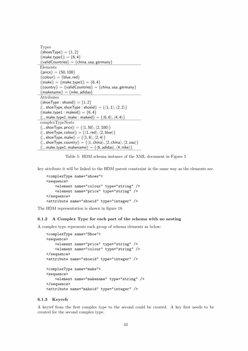
Types〈〈shoesType〉〉 = {1, 2}〈〈make type1〉〉 = {6, 4}〈〈validCountries〉〉 = {china, usa, germany}Elements〈〈price〉〉 = {50, 100}〈〈colour〉〉 = {blue, red}〈〈make〉〉 = 〈〈make type1〉〉 = {6, 4}〈〈country〉〉 = 〈〈validCountries〉〉 = {china, usa, germany}〈〈makename〉〉 = {nike, adidas}Attributes〈〈shoeType : shoeid〉〉 = {1, 2}〈〈 , shoeType, shoeType : shoeid〉〉 = {〈1, 1〉, 〈2, 2〉}〈〈make type1 : makeid〉〉 = {6, 4}〈〈 ,make type1,make : makeid〉〉 = {〈6, 6〉, 〈4, 4〉}complexTypeNests〈〈 , shoeType, price〉〉 = {〈1, 50〉, 〈2, 100〉}〈〈 , shoeType, colour〉〉 = {〈1, red〉, 〈2, blue〉}〈〈 , shoeType,make〉〉 = {〈1, 6〉, 〈2, 4〉}〈〈 , shoeType, country〉〉 = {〈1, china〉, 〈2, china〉, 〈2, usa〉}〈〈 ,make type1,makename〉〉 = {〈6, adidas〉, 〈4, nike〉}
Table 5: HDM schema instance of the XML document in Figure 5
key attribute it will be linked to the HDM parent constraint in the same way as the elements are.
<complexType name="shoes"><sequence>
<element name="colour" type="string" /><element name="price" type="string" />
</sequence><attribute name="shoeid" type="integer" />
The HDM representation is shown in figure 18.
6.1.2 A Complex Type for each part of the schema with no nesting
A complex type represents each group of schema elements as below:
<complexType name="Shoe"><sequence>
<element name="price" type="string" /><element name="colour" type="string" />
</sequence><attribute name="shoeid" type="integer" />
<complexType name="make"><sequence>
<element name="makename" type="string" /></sequence><attribute name="makeid" type="integer" />
6.1.3 Keyrefs
A keyref from the first complex type to the second could be created. A key first needs to becreated for the second complex type.
42

<key name = "unique_makeid"><selector xpath="./makes"/><field xpath="@makeid"/>
<key>
and then a keyref to it created.
<keyref name = "fk_shoe_makeid" refer="unique_makeid"><selector xpath="./shoes" /><field xpath="@makerefid"/>
</keyref>
The Shoe complex type will now look like this:
<complexType name="Shoe"><sequence>
<element name="makerefid" type="integer" /><element name="price" /><element name="colour" />
</sequence><attribute name="shoeid" />
The HDM representation is shown in figure 19 part (ii). The keyref is represented by the edgelinking the shoemakeid node to the makeid node.
6.1.4 Nesting
If we wished to nest the country the shoe was made in inside the shoe we could define a newcomplex type to store the country name and an id as follows:
<complexType name="countries"><sequence>
<element name="countryname" type="string" /></sequence><attribute name="countryid" type="integer" />
We could then nest an element of this type inside shoes as follows. We represent the fact thata shoe can be made in more than one country by making the maxOccurs occurrence constraint onshoescountries unbounded:
<complexType name="shoe">
<sequence>
<element name="price" type="string" />
<element name="colour" type="string" />
<element name="make" type="string" />
<element name="shoescountries" type="countries" maxOccurs = "unbounded" />
</sequence>
<attribute name="shoeid" type="integer" />
The HDM representation is shown in figure 20 part (ii). The nesting is represented by thenode named after the element and the edges linking it to its own type and its parent type.
6.2 The Primitive Transformations
We now present the primitive transformations on the Automed XML Schema model. These areautomatically derivable from the definitions of the XML Schema constructs given in Table 3. Notethat the provisos for addEdge and addNode apply to all the operations below.
43
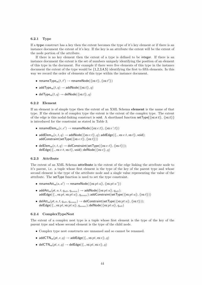
6.2.1 Type
If a type construct has a key then the extent becomes the type of it’s key element or if there is aninstance document the extent of it’s key. If the key is an attribute the extent will be the extent ofthe node portion of the attribute.
If there is no key element then the extent of a type is defined to be integer. If there is aninstance document the extent is the set of numbers uniquely identifying the position of an elementof this type in the document. For example if there were five elements of this type in the instancedocument the extent of the type would be {1,2,3,4,5} identifying the first to fifth elements. In thisway we record the order of elements of this type within the instance document.
• renameTypexs(t, t′) → renameNode(〈〈xs:t〉〉, 〈〈xs:t ′〉〉)
• addTypexs(t, q) → addNode(〈〈xs:t〉〉, q)
• delTypexs(t, q) → delNode(〈〈xs:t〉〉, q)
6.2.2 Element
If an element is of simple type then the extent of an XML Schema element is the name of thattype. If the element is of complex type the extent is the extent of the complex type. The extentof the edge is this nodal-linking construct is void. A shorthand function setType(〈〈xs:e:t〉〉, 〈〈xs:t〉〉)is introduced for the constraint as stated in Table 3.
• renameElemxs(e, e′) → renameNode(〈〈xs:e:t〉〉, 〈〈xs:e’ :t〉〉)
• addElemxs(e, t, q) → addNode(〈〈xs:e:t〉〉, q); addEdge(〈〈 , xs:e:t , xs:t〉〉, void);addConstraint(setType(〈〈xs:e:t〉〉, 〈〈xs:t〉〉))
• delElemxs(e, t, q) → delConstraint(setType(〈〈xs:e:t〉〉, 〈〈xs:t〉〉));delEdge(〈〈 , xs:e:t , xs:t〉〉, void); delNode(〈〈xs:e〉〉, q)
6.2.3 Attribute
The extent of an XML Schema attribute is the extent of the edge linking the attribute node toit’s parent, i.e. a tuple whose first element is the type of the key of the parent type and whosesecond element is the type of the attribute node and a single value representing the value of theattribute. The setType function is used to set the type constraint.
• renameAttxs(a, a′) → renameNode(〈〈xs:pt :a〉〉, 〈〈xs:pt :a’ 〉〉)
• addAttxs(pt, a, t, qatt, qassoc) → addNode(〈〈xs:pt :a〉〉, qatt);addEdge(〈〈 , xs:pt , xs:pt :a〉〉, qassoc); addConstraint(setType(〈〈xs:pt :a〉〉, 〈〈xs:t〉〉))
• delAttxs(pt, a, t, qatt, qassoc) → delConstraint(setType(〈〈xs:pt :a〉〉, 〈〈xs:t〉〉));delEdge(〈〈 , xs:pt , xs:pt :a〉〉, qassoc); delNode(〈〈xs:pt :a〉〉, qatt)
6.2.4 ComplexTypeNest
The extent of a complex nest type is a tuple whose first element is the type of the key of theparent type and whose second element is the type of the child node.
• Complex type nest constructs are unnamed and so cannot be renamed.
• addCTNxs(pt, e, q) → addEdge(〈〈 , xs:pt , xs:e〉〉, q)
• delCTNxs(pt, e, q) → delEdge(〈〈 , xs:pt , xs:e〉〉, q)
44
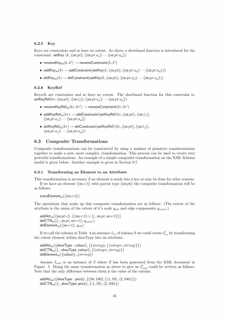
6.2.5 Key
Keys are constraints and so have no extent. As above a shorthand function is introduced for theconstraint: setKey (k, 〈〈xs:pt〉〉, 〈〈xs:pt :a1〉〉 · · · 〈〈xs:pt :an〉〉)
• renameKeyxs(k, k′) → renameConstraint(k, k′)
• addKeyxs(k) → addConstraint(setKey(k, 〈〈xs:pt〉〉, 〈〈xs:pt :a1〉〉 · · · 〈〈xs:pt :an〉〉))
• delKeyxs(k) → delConstraint(setKey(k, 〈〈xs:pt〉〉, 〈〈xs:pt :a1〉〉 · · · 〈〈xs:pt :an〉〉))
6.2.6 KeyRef
Keyrefs are constraints and so have no extent. The shorthand function for this constraint is:setKeyRef(kr, 〈〈xs:pt〉〉, 〈〈xs:tf 〉〉, 〈〈xs:pt :a1〉〉 · · · 〈〈xs:pt :an〉〉)
• renameKeyRefxs(kr, kr′) → renameConstraint(kr, kr′)
• addKeyRefxs(kr) → addConstraint(setKeyRef(kr, 〈〈xs:pt〉〉, 〈〈xs:tf 〉〉,〈〈xs:pt :a1〉〉 · · · 〈〈xs:pt :an〉〉)
• delKeyRefxs(kr) → delConstraint(setKeyRef((kr, 〈〈xs:pt〉〉, 〈〈xs:tf 〉〉,〈〈xs:pt :a1〉〉 · · · 〈〈xs:pt :an〉〉)
6.3 Composite Transformations
Composite transformations can be constructed by using a number of primitive transformationstogether to make a new, more complex, transformation. This process can be used to create verypowerful transformations. An example of a simple composite transformation on the XML Schemamodel is given below. Another example is given in Section 9.7.
6.3.1 Transforming an Element to an Attribute
This transformation is necessary if an element is made into a key or may be done for other reasons.If we have an element 〈〈xs:e:t〉〉 with parent type 〈〈xs:pt〉〉 the composite transformation will be
as follows:
transElementxs(〈〈xs:e:t〉〉)
The operations that make up this composite transformation are as follows: (The extent of theattribute is the union of the extent of it’s node qatt and edge components qassoc.)
addAttxs(〈〈xs:pt :e〉〉, {〈〈xs:e:t〉〉 ∪ 〈〈 , xs:pt , xs:e:t〉〉})delCTNxs(〈〈 , xs:pt , xs:e:t〉〉, qassoc)delElementxs(〈〈xs:e:t〉〉, qatt)
If we call the schema in Table 4 an instance Ixs of schema S we could create I ′xs by transformingthe colour element within shoeType into an attribute.
addAttxs(〈〈shoeType : colour〉〉, {{string}, {〈integer, string〉}})delCTNxs(〈〈 , shoeType, colour〉〉, {〈integer, string〉})delElementxs(〈〈colour〉〉, {string})
Assume Ixml is an instance of S where S has been generated from the XML document inFigure 5. Doing the same transformation as above to give us I ′xml could be written as follows.Note that the only difference between them is the value of the extents.
addAttxs(〈〈shoeType : price〉〉, {{50, 100}, {〈1, 50〉, 〈2, 100〉}})delCTNxs(〈〈 , shoeType, price〉〉, {〈1, 50〉, 〈2, 100〉})
45
delElementxs(〈〈price〉〉, {50, 100})
We can see that in both cases ExtS,I = ExtS,I′ .
46
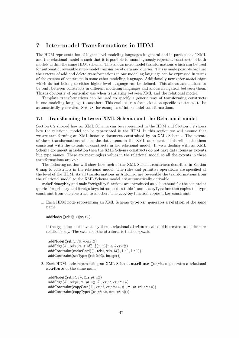
7 Inter-model Transformations in HDM
The HDM representation of higher level modeling languages in general and in particular of XMLand the relational model is such that it is possible to unambiguously represent constructs of bothmodels within the same HDM schema. This allows inter-model transformations which can be usedfor automatic, reversible inter-model translation of data and queries. This is made possible becausethe extents of add and delete transformations in one modeling language can be expressed in termsof the extents of constructs in some other modeling language. Additionally new inter-model edgeswhich do not belong to either higher-level language can be defined. This allows associations tobe built between constructs in different modeling languages and allows navigation between them.This is obviously of particular use when translating between XML and the relational model.
Template transformations can be used to specify a generic way of transforming constructsin one modeling language to another. This enables transformations on specific constructs to beautomatically generated. See [28] for examples of inter-model transformations.
7.1 Transforming between XML Schema and the Relational model
Section 6.2 showed how an XML Schema can be represented in the HDM and Section 5.2 showshow the relational model can be represented in the HDM. In this section we will assume thatwe are transforming an XML instance document constrained by an XML Schema. The extentsof these transformations will be the data items in the XML document. This will make themconsistent with the extents of constructs in the relational model. If we a dealing with an XMLSchema document in isolation then the XML Schema constructs do not have data items as extentsbut type names. These are meaningless values in the relational model so all the extents in thesetransformations are void.
The following section will show how each of the XML Schema constructs described in Section6 map to constructs in the relational model. The rules and primitive operations are specified atthe level of the HDM. As all transformations in Automed are reversible the transformations fromthe relational model to the XML Schema model are automatically derivable.
makePrimaryKey and makeForeignKey functions are introduced as a shorthand for the constraintqueries for primary and foreign keys introduced in table 1 and a copyType function copies the typeconstraint from one construct to another. The copyKey function copies a key constraint.
1. Each HDM node representing an XML Schema type xs:t generates a relation of the samename.
addNode(〈〈rel:t〉〉, (〈〈xs:t〉〉)
If the type does not have a key then a relational attribute called id is created to be the newrelation’s key. The extent of the attribute is that of 〈〈xs:t〉〉.
addNode(〈〈rel:t :id〉〉, 〈〈xs:t :〉〉)addEdge(〈〈 , rel:t , rel:t :id〉〉, {〈x, x〉|x ∈ 〈〈xs:t :〉〉)addConstraint(makeCard(〈〈 , rel:t , rel:t :id〉〉, 1 : 1, 1 : 1))addConstraint(setType(〈〈rel:t :id〉〉, integer))
2. Each HDM node representing an XML Schema attribute 〈〈xs:pt :a〉〉 generates a relationalattribute of the same name:
addNode(〈〈rel:pt :a〉〉, 〈〈xs:pt :a〉〉)addEdge(〈〈 , rel:pt , rel:pt :a〉〉, 〈〈 , xs:pt , xs:pt :a〉〉)addConstraint(copyCard(〈〈 , xs:pt , xs:pt :a〉〉, 〈〈 , rel:pt , rel:pt :a〉〉))addConstraint(copyType(〈〈xs:pt :a〉〉, 〈〈rel:pt :a〉〉))
47

3. Each HDM node representing an XML Schema element of simple type and the complex-TypeNest construct linking it to it’s parent, generate a relational attribute of the samename as the element:
addNode(〈〈rel:pt :e〉〉, 〈〈xs:e:t〉〉)addEdge(〈〈 , rel:pt , rel:pt :e〉〉, 〈〈 , xs:pt , xs:e:t〉〉)addConstraint(copyCard(〈〈 , xs:pt , xs:e:t〉〉, 〈〈 , rel:pt , rel:pt :e〉〉))addConstraint(copyType(〈〈xs:e:t〉〉, 〈〈rel:pt :e〉〉))
Note that during the reverse operation relational key attributes will generate XML Schemaattributes while non-key attributes will generate XML Schema elements.
4. Each HDM node representing an XML Schema element of complex type and the complex-TypeNest construct linking it to it’s parent will generate a relation with the same nameas the element, linking the parent relation of the element to the relation representing it’stype. The new relation will have two attributes representing the keys of the two linkedrelations. In this way nests are turned into link tables. The types of the two columns arethe types of the keys of the complex types they are linking, k1, k2.
addNode(〈〈rel:e〉〉, 〈〈 , xs:pt , xs:e:t〉〉))addNode(〈〈rel:e:t〉〉, {〈x〉|〈x, y〉 ∈ 〈〈 , xs:pt , xs:e:t〉〉})addEdge(〈〈 , rel:e, rel:e:t〉〉, 〈〈 , xs:pt , xs:e〉〉)addConstraint(makeCard(〈〈 , rel:e, rel:e:t〉〉, 1 : 1, 1 : 1))addConstraint(copyType(〈〈xs:t :k1〉〉, 〈〈rel:e:t〉〉))addNode(〈〈rel:e:pt〉〉, {〈y〉|〈x, y〉 ∈ 〈〈 , xs:pt , xs:e:t〉〉})addEdge(〈〈 , rel:e, rel:e:pt〉〉, 〈〈 , xs:pt , xs:e:t〉〉)addConstraint(makeCard(〈〈 , rel:e, rel:e:pt〉〉, 1 : 1, 1 : 1))addConstraint(copyType(〈〈xs:pt :k2〉〉, 〈〈rel:pt :e〉〉))
A primary key constraint consisting of both of the new columns is added.
addConstraint(makePrimaryKey(〈〈rel:e, rel:e:pt , rel:e:t〉〉))
A foreign key constraint is also added to each of the new columns.
addConstraint(makeForeignKey(〈〈rel:e, rel:t , rel:e:t〉〉))addConstraint(makeForeignKey(〈〈rel:e, rel:pt , rel:e:pt〉〉))
5. An XML Schema element with an maximum occurrence constraint greater than 1 willgenerate a relation linking the parent to instances of the element. The relation will havetwo attributes, one to hold the key of the parent with type k and one for the element.addNode(〈〈rel:e〉〉, 〈〈 , xs:pt , xs:e:t〉〉))addNode(〈〈rel:e:pt〉〉, {〈x〉|〈x, y〉 ∈ 〈〈 , xs:pt , xs:e:t〉〉})addEdge(〈〈 , rel:e, rel:e:pt〉〉, 〈〈 , xs:pt , xs:e:t〉〉)addConstraint(makeCard(〈〈 , rel:e, rel:e:t〉〉, 1 : 1, 1 : 1))addConstraint(copyType(〈〈xs:t :k〉〉, 〈〈rel:e:t〉〉))addNode(〈〈rel:e:e〉〉, {〈y〉|〈x, y〉 ∈ 〈〈 , xs:pt , xs:e:t〉〉})addEdge(〈〈 , rel:e, rel:e:e〉〉, 〈〈 , xs:pt , xs:e:t〉〉)addConstraint(makeCard(〈〈 , rel:e, rel:e:pt〉〉, 1 : 1, 1 : 1))addConstraint(copyType(〈〈xs:e:t〉〉, 〈〈rel:pt :e〉〉))
The primary key again consists of both of the new columns.
addConstraint(makePrimaryKey(〈〈rel:e, rel:e:pt , rel:e:t〉〉))
48
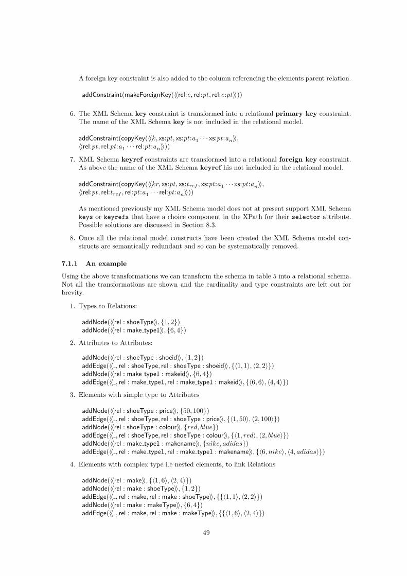
A foreign key constraint is also added to the column referencing the elements parent relation.
addConstraint(makeForeignKey(〈〈rel:e, rel:pt , rel:e:pt〉〉))
6. The XML Schema key constraint is transformed into a relational primary key constraint.The name of the XML Schema key is not included in the relational model.
addConstraint(copyKey(〈〈k, xs:pt , xs:pt :a1 · · · xs:pt :an〉〉,〈〈rel:pt , rel:pt :a1 · · · rel:pt :an〉〉))
7. XML Schema keyref constraints are transformed into a relational foreign key constraint.As above the name of the XML Schema keyref his not included in the relational model.
addConstraint(copyKey(〈〈kr, xs:pt , xs:tref , xs:pt :a1 · · · xs:pt :an〉〉,〈〈rel:pt , rel:tref , rel:pt :a1 · · · rel:pt :an〉〉))
As mentioned previously my XML Schema model does not at present support XML Schemakeys or keyrefs that have a choice component in the XPath for their selector attribute.Possible solutions are discussed in Section 8.3.
8. Once all the relational model constructs have been created the XML Schema model con-structs are semantically redundant and so can be systematically removed.
7.1.1 An example
Using the above transformations we can transform the schema in table 5 into a relational schema.Not all the transformations are shown and the cardinality and type constraints are left out forbrevity.
1. Types to Relations:
addNode(〈〈rel : shoeType〉〉, {1, 2})addNode(〈〈rel : make type1〉〉, {6, 4})
2. Attributes to Attributes:
addNode(〈〈rel : shoeType : shoeid〉〉, {1, 2})addEdge(〈〈 , rel : shoeType, rel : shoeType : shoeid〉〉, {〈1, 1〉, 〈2, 2〉})addNode(〈〈rel : make type1 : makeid〉〉, {6, 4})addEdge(〈〈 , rel : make type1, rel : make type1 : makeid〉〉, {〈6, 6〉, 〈4, 4〉})
3. Elements with simple type to Attributes
addNode(〈〈rel : shoeType : price〉〉, {50, 100})addEdge(〈〈 , rel : shoeType, rel : shoeType : price〉〉, {〈1, 50〉, 〈2, 100〉})addNode(〈〈rel : shoeType : colour〉〉, {red, blue})addEdge(〈〈 , rel : shoeType, rel : shoeType : colour〉〉, {〈1, red〉, 〈2, blue〉})addNode(〈〈rel : make type1 : makename〉〉, {nike, adidas})addEdge(〈〈 , rel : make type1, rel : make type1 : makename〉〉, {〈6, nike〉, 〈4, adidas〉})
4. Elements with complex type i.e nested elements, to link Relations
addNode(〈〈rel : make〉〉, {〈1, 6〉, 〈2, 4〉})addNode(〈〈rel : make : shoeType〉〉, {1, 2})addEdge(〈〈 , rel : make, rel : make : shoeType〉〉, {{〈1, 1〉, 〈2, 2〉})addNode(〈〈rel : make : makeType〉〉, {6, 4})addEdge(〈〈 , rel : make, rel : make : makeType〉〉, {{〈1, 6〉, 〈2, 4〉})
49
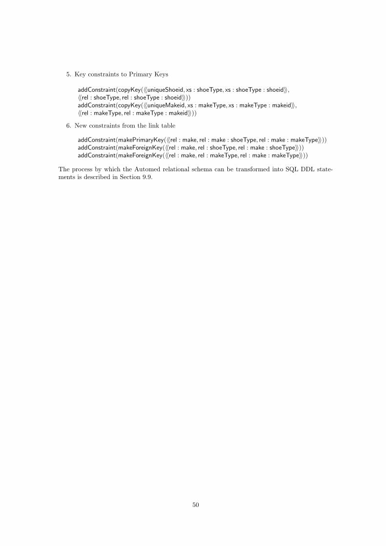
5. Key constraints to Primary Keys
addConstraint(copyKey(〈〈uniqueShoeid, xs : shoeType, xs : shoeType : shoeid〉〉,〈〈rel : shoeType, rel : shoeType : shoeid〉〉))addConstraint(copyKey(〈〈uniqueMakeid, xs : makeType, xs : makeType : makeid〉〉,〈〈rel : makeType, rel : makeType : makeid〉〉))
6. New constraints from the link table
addConstraint(makePrimaryKey(〈〈rel : make, rel : make : shoeType, rel : make : makeType〉〉))addConstraint(makeForeignKey(〈〈rel : make, rel : shoeType, rel : make : shoeType〉〉))addConstraint(makeForeignKey(〈〈rel : make, rel : makeType, rel : make : makeType〉〉))
The process by which the Automed relational schema can be transformed into SQL DDL state-ments is described in Section 9.9.
50
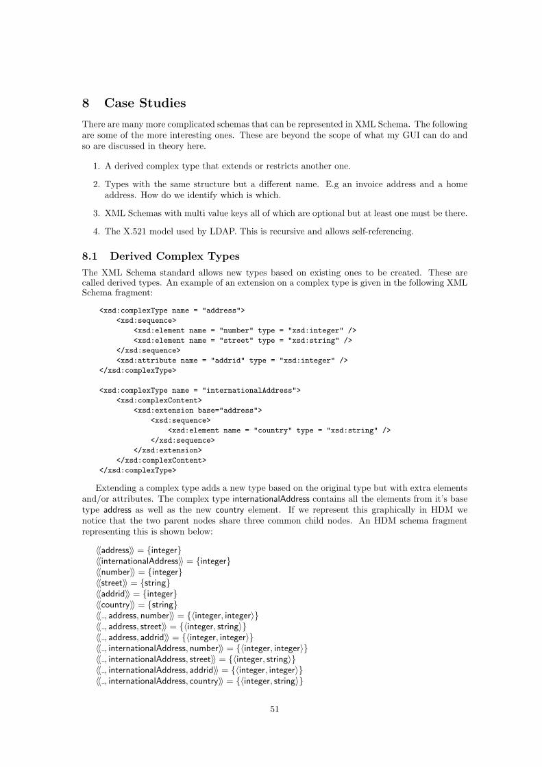
8 Case Studies
There are many more complicated schemas that can be represented in XML Schema. The followingare some of the more interesting ones. These are beyond the scope of what my GUI can do andso are discussed in theory here.
1. A derived complex type that extends or restricts another one.
2. Types with the same structure but a different name. E.g an invoice address and a homeaddress. How do we identify which is which.
3. XML Schemas with multi value keys all of which are optional but at least one must be there.
4. The X.521 model used by LDAP. This is recursive and allows self-referencing.
8.1 Derived Complex Types
The XML Schema standard allows new types based on existing ones to be created. These arecalled derived types. An example of an extension on a complex type is given in the following XMLSchema fragment:
<xsd:complexType name = "address">
<xsd:sequence>
<xsd:element name = "number" type = "xsd:integer" />
<xsd:element name = "street" type = "xsd:string" />
</xsd:sequence>
<xsd:attribute name = "addrid" type = "xsd:integer" />
</xsd:complexType>
<xsd:complexType name = "internationalAddress">
<xsd:complexContent>
<xsd:extension base="address">
<xsd:sequence>
<xsd:element name = "country" type = "xsd:string" />
</xsd:sequence>
</xsd:extension>
</xsd:complexContent>
</xsd:complexType>
Extending a complex type adds a new type based on the original type but with extra elementsand/or attributes. The complex type internationalAddress contains all the elements from it’s basetype address as well as the new country element. If we represent this graphically in HDM wenotice that the two parent nodes share three common child nodes. An HDM schema fragmentrepresenting this is shown below:
〈〈address〉〉 = {integer}〈〈internationalAddress〉〉 = {integer}〈〈number〉〉 = {integer}〈〈street〉〉 = {string}〈〈addrid〉〉 = {integer}〈〈country〉〉 = {string}〈〈 , address, number〉〉 = {〈integer, integer〉}〈〈 , address, street〉〉 = {〈integer, string〉}〈〈 , address, addrid〉〉 = {〈integer, integer〉}〈〈 , internationalAddress, number〉〉 = {〈integer, integer〉}〈〈 , internationalAddress, street〉〉 = {〈integer, string〉}〈〈 , internationalAddress, addrid〉〉 = {〈integer, integer〉}〈〈 , internationalAddress, country〉〉 = {〈integer, string〉}
51
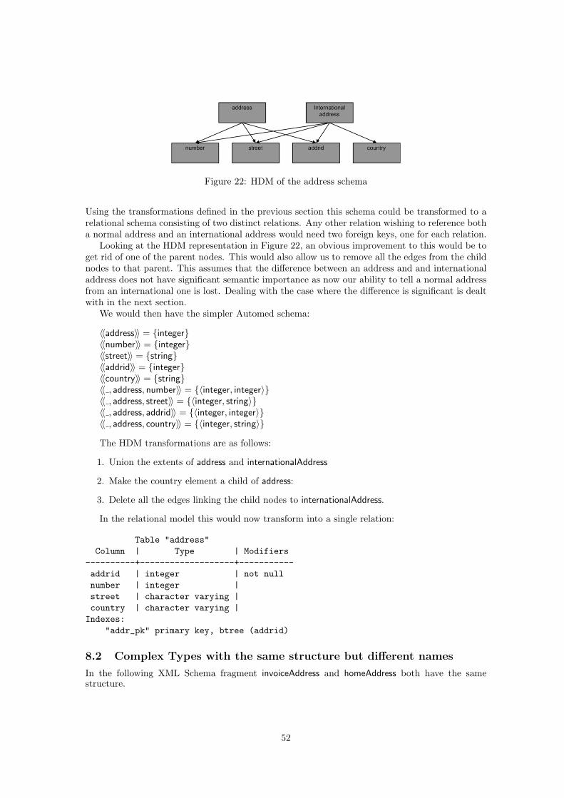
Figure 22: HDM of the address schema
Using the transformations defined in the previous section this schema could be transformed to arelational schema consisting of two distinct relations. Any other relation wishing to reference botha normal address and an international address would need two foreign keys, one for each relation.
Looking at the HDM representation in Figure 22, an obvious improvement to this would be toget rid of one of the parent nodes. This would also allow us to remove all the edges from the childnodes to that parent. This assumes that the difference between an address and and internationaladdress does not have significant semantic importance as now our ability to tell a normal addressfrom an international one is lost. Dealing with the case where the difference is significant is dealtwith in the next section.
We would then have the simpler Automed schema:
〈〈address〉〉 = {integer}〈〈number〉〉 = {integer}〈〈street〉〉 = {string}〈〈addrid〉〉 = {integer}〈〈country〉〉 = {string}〈〈 , address, number〉〉 = {〈integer, integer〉}〈〈 , address, street〉〉 = {〈integer, string〉}〈〈 , address, addrid〉〉 = {〈integer, integer〉}〈〈 , address, country〉〉 = {〈integer, string〉}
The HDM transformations are as follows:
1. Union the extents of address and internationalAddress
2. Make the country element a child of address:
3. Delete all the edges linking the child nodes to internationalAddress.
In the relational model this would now transform into a single relation:
Table "address"Column | Type | Modifiers
----------+-------------------+-----------addrid | integer | not nullnumber | integer |street | character varying |country | character varying |Indexes:
"addr_pk" primary key, btree (addrid)
8.2 Complex Types with the same structure but different names
In the following XML Schema fragment invoiceAddress and homeAddress both have the samestructure.
52
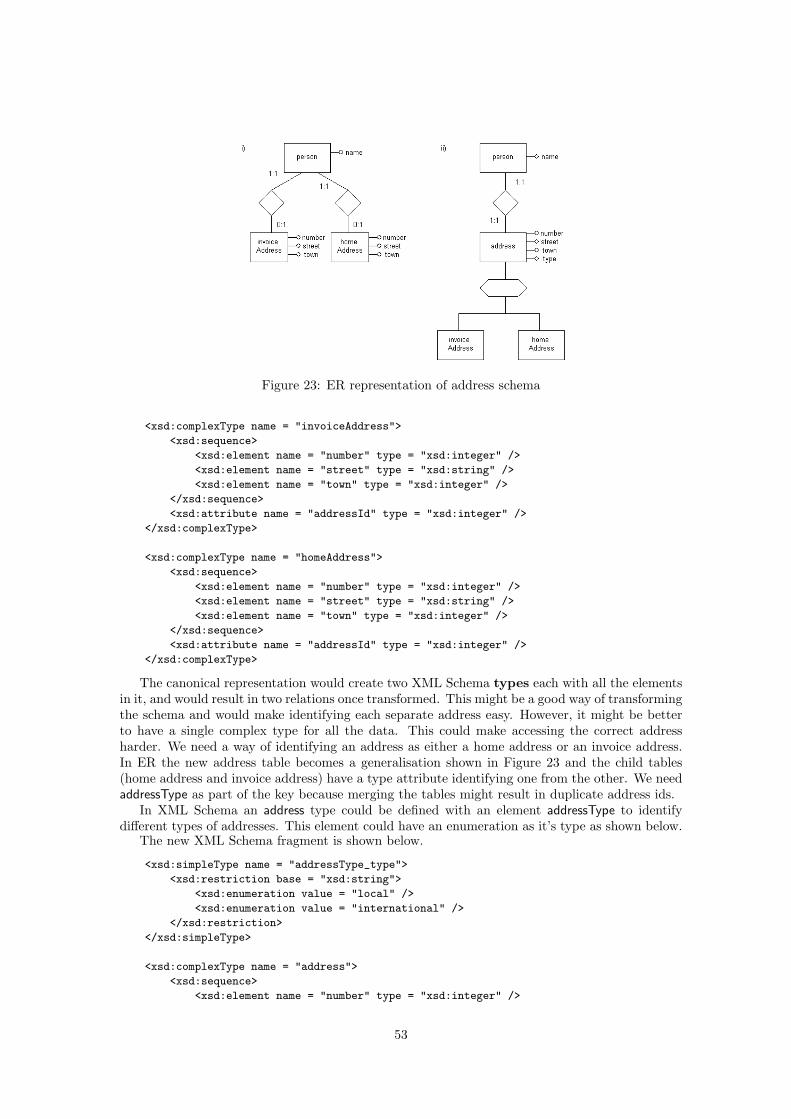
Figure 23: ER representation of address schema
<xsd:complexType name = "invoiceAddress">
<xsd:sequence>
<xsd:element name = "number" type = "xsd:integer" />
<xsd:element name = "street" type = "xsd:string" />
<xsd:element name = "town" type = "xsd:integer" />
</xsd:sequence>
<xsd:attribute name = "addressId" type = "xsd:integer" />
</xsd:complexType>
<xsd:complexType name = "homeAddress">
<xsd:sequence>
<xsd:element name = "number" type = "xsd:integer" />
<xsd:element name = "street" type = "xsd:string" />
<xsd:element name = "town" type = "xsd:integer" />
</xsd:sequence>
<xsd:attribute name = "addressId" type = "xsd:integer" />
</xsd:complexType>
The canonical representation would create two XML Schema types each with all the elementsin it, and would result in two relations once transformed. This might be a good way of transformingthe schema and would make identifying each separate address easy. However, it might be betterto have a single complex type for all the data. This could make accessing the correct addressharder. We need a way of identifying an address as either a home address or an invoice address.In ER the new address table becomes a generalisation shown in Figure 23 and the child tables(home address and invoice address) have a type attribute identifying one from the other. We needaddressType as part of the key because merging the tables might result in duplicate address ids.
In XML Schema an address type could be defined with an element addressType to identifydifferent types of addresses. This element could have an enumeration as it’s type as shown below.
The new XML Schema fragment is shown below.
<xsd:simpleType name = "addressType_type">
<xsd:restriction base = "xsd:string">
<xsd:enumeration value = "local" />
<xsd:enumeration value = "international" />
</xsd:restriction>
</xsd:simpleType>
<xsd:complexType name = "address">
<xsd:sequence>
<xsd:element name = "number" type = "xsd:integer" />
53
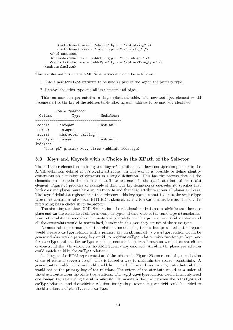
<xsd:element name = "street" type = "xsd:string" />
<xsd:element name = "town" type = "xsd:string" />
</xsd:sequence>
<xsd:attribute name = "addrId" type = "xsd:integer" />
<xsd:attribute name = "addrType" type = "addressType_type" />
</xsd:complexType>
The transformations on the XML Schema model would be as follows:
1. Add a new addrType attribute to be used as part of the key in the primary type.
2. Remove the other type and all its elements and edges.
This can now be represented as a single relational table. The new addrType element wouldbecome part of the key of the address table allowing each address to be uniquely identified.
Table "address"Column | Type | Modifiers
----------+-------------------+-----------addrId | integer | not nullnumber | integer |street | character varying |addrType | integer | not nullIndexes:
"addr_pk" primary key, btree (addrid, addrtype)
8.3 Keys and Keyrefs with a Choice in the XPath of the Selector
The selector element in both key and keyref definitions can have multiple components in theXPath definition defined in it’s xpath attribute. In this way it is possible to define identityconstraints on a number of elements in a single definition. This has the proviso that all theelements must contain the element or attribute referenced in the xpath attribute of the fieldelement. Figure 24 provides an example of this. The key definition unique vehicleId specifies thatboth cars and planes must have an id attribute and that that attribute across all planes and cars.The keyref definition registrationId that references this key specifies that the id in the vehicleTypetype must contain a value from EITHER a plane element OR a car element because the key it’sreferencing has a choice in its selector.
Transforming the above XML Schema into the relational model is not straightforward becauseplane and car are elements of different complex types. If they were of the same type a transforma-tion to the relational model would create a single relation with a primary key on id attribute andall the constraints would be maintained, however in this case they are not of the same type.
A canonical transformation to the relational model using the method presented in this reportwould create a carType relation with a primary key on id, similarly a planeType relation would begenerated also with a primary key on id. A registrationType relation with two foreign keys, onefor planeType and one for carType would be needed. This transformation would lose the eitheror constraint that the choice on the XML Schema key enforced. An id in the planeType relationcould match an id in the carType relation.
Looking at the HDM representation of the schema in Figure 25 some sort of generalisationof the id element suggests itself. This is indeed a way to maintain the correct constraints. Ageneralisation table called vehicleId could be created. It would have a single attribute id thatwould act as the primary key of the relation. The extent of the attribute would be a union ofthe id attributes from the other two relations. The registrationType relation would then only needone foreign key referencing the id in vehicleId. To maintain the link between the planeType andcarType relations and the vehicleId relation, foreign keys referencing vehicleId could be added tothe id attributes of planeType and carType.
54

<?xml version="1.0" encoding="UTF-8"?>
<xsd:schema xmlns:xsd="http://www.w3.org/2001/XMLSchema"><xsd:complexType name = "planeType"><xsd:sequence><xsd:element name = "wingspan"></xsd:element></xsd:sequence><xsd:attribute name = "id" type = "xsd:integer"></xsd:attribute></xsd:complexType><xsd:complexType name = "carType"><xsd:sequence><xsd:element name = "cc"></xsd:element></xsd:sequence><xsd:attribute name = "id" type = "xsd:integer"></xsd:attribute></xsd:complexType><xsd:complexType name = "registrationType"><xsd:sequence><xsd:element name = "county"></xsd:element></xsd:sequence><xsd:attribute name = "id" type = "xsd:integer"></xsd:attribute></xsd:complexType><xsd:complexType name = "databaseType"><xsd:sequence><xsd:element name = "plane" type = "planeType" minOccurs="0" maxOccurs="unbounded"></xsd:element><xsd:element name = "car" type = "carType" minOccurs="0" maxOccurs="unbounded"></xsd:element><xsd:element name = "registration" type = "registrationType" minOccurs="0" maxOccurs="unbounded"></xsd:element></xsd:sequence></xsd:complexType><xsd:element name = "vehicleDatabase" type = "databaseType">
<xsd:key name = "unique_vehicleId"><xsd:selector xpath="./plane | ./car"/><xsd:field xpath="@id"/></xsd:key>
<xsd:keyref name = "registrationId" refer = "unique_vehicleId"><xsd:selector xpath="./registration"/><xsd:field xpath="@id"/></xsd:keyref>
</xsd:element></xsd:schema>
Figure 24: XML Schema fragment showing a choice in the selector XPath
Figure 25: HDM of the vehicle schema
55
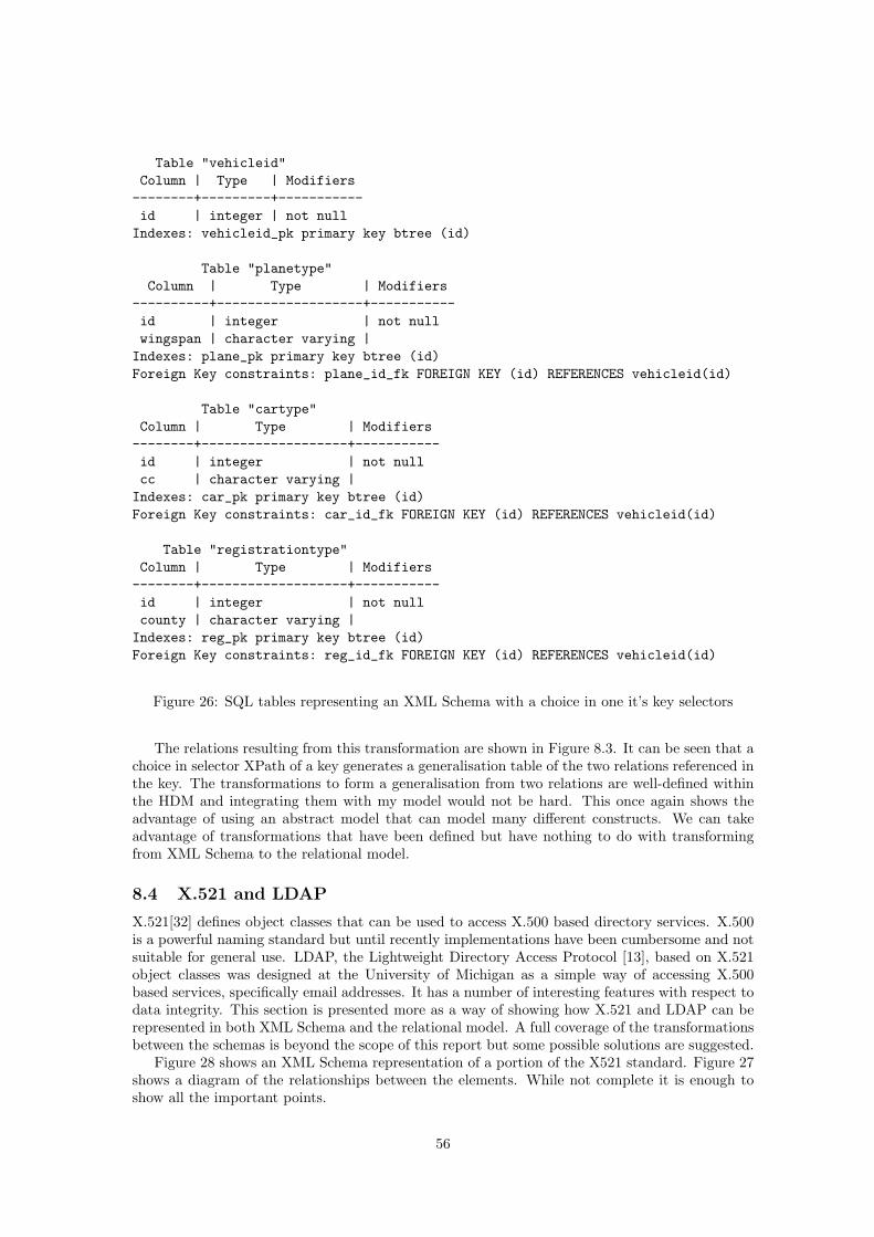
Table "vehicleid"Column | Type | Modifiers--------+---------+-----------id | integer | not nullIndexes: vehicleid_pk primary key btree (id)
Table "planetype"Column | Type | Modifiers
----------+-------------------+-----------id | integer | not nullwingspan | character varying |Indexes: plane_pk primary key btree (id)Foreign Key constraints: plane_id_fk FOREIGN KEY (id) REFERENCES vehicleid(id)
Table "cartype"Column | Type | Modifiers--------+-------------------+-----------id | integer | not nullcc | character varying |Indexes: car_pk primary key btree (id)Foreign Key constraints: car_id_fk FOREIGN KEY (id) REFERENCES vehicleid(id)
Table "registrationtype"Column | Type | Modifiers--------+-------------------+-----------id | integer | not nullcounty | character varying |Indexes: reg_pk primary key btree (id)Foreign Key constraints: reg_id_fk FOREIGN KEY (id) REFERENCES vehicleid(id)
Figure 26: SQL tables representing an XML Schema with a choice in one it’s key selectors
The relations resulting from this transformation are shown in Figure 8.3. It can be seen that achoice in selector XPath of a key generates a generalisation table of the two relations referenced inthe key. The transformations to form a generalisation from two relations are well-defined withinthe HDM and integrating them with my model would not be hard. This once again shows theadvantage of using an abstract model that can model many different constructs. We can takeadvantage of transformations that have been defined but have nothing to do with transformingfrom XML Schema to the relational model.
8.4 X.521 and LDAP
X.521[32] defines object classes that can be used to access X.500 based directory services. X.500is a powerful naming standard but until recently implementations have been cumbersome and notsuitable for general use. LDAP, the Lightweight Directory Access Protocol [13], based on X.521object classes was designed at the University of Michigan as a simple way of accessing X.500based services, specifically email addresses. It has a number of interesting features with respect todata integrity. This section is presented more as a way of showing how X.521 and LDAP can berepresented in both XML Schema and the relational model. A full coverage of the transformationsbetween the schemas is beyond the scope of this report but some possible solutions are suggested.
Figure 28 shows an XML Schema representation of a portion of the X521 standard. Figure 27shows a diagram of the relationships between the elements. While not complete it is enough toshow all the important points.
56
Figure 27: A portion of the X521 naming standard
8.4.1 Self referencing and Recursion
We can see from figure 27 that the locality node can contain itself. In XML Schema, relationshipsbetween elements can be created with nesting or with key/keyref combinations. In the X.521model we can model the self-referencing nature of the locality node by nesting locality node insideitself. In the relational model this is done with self-referencing foreign keys.
As well as self referencing nodes groups of nodes together can create recursive definitions. Forexample an organisation can contain a locality which in turn can contain an organisation whichcould contain another locality etc. In XML Schema these are represented as group of complextypes that can reference each other while in the relational model they become groups of relationswith foreign keys that reference each other.
Using the method described in this report the X.521 XML Schema could be represented witha relation for each node of the X.521 model with relational attributes for each XML Schemaattribute and an additional id attribute to act as a foreign key. The nesting of different types ofnode could be represented as link tables.
8.4.2 LDAP
The representation described above will work for a description of entire organisational hierarchywhere the root may include a number of countries followed by some localities that may or maynot have sub-elements. The structure of an LDAP address is also hierarchical is nature. Eachentry in an LDAP database has a unique Distinguished Name or DN. This name is built upfrom the unique Relative Distinguished Names (RDN) at each level of the naming hierarchyabove the name we are interested in. An example of an LDAP address is shown below:
dn: cn = andrew, o = ic, c = uk
Starting from the root node in Figure 27 and reading the address backwards it must have oneof a country, locality or organisation not more. Here we have a country with an RDN of uk. Thenext element must then be one of a country or an organization. We chose an organisation with anRDN of ic. The final element must be a locality, an organisational unit, an organisation role or aperson. We chose a person. The LDAP standard includes an inetOrgPerson object that includesthe cn attribute. In this way the DN is built up.
The constraint that each level of the hierarchy should be one of a number of options is notenforced by the XML Schema in Figure 28. It would allow a country to be followed by an unlimitednumber of organisations for example. XML Schema does, however, provide a mechanism to achievethis ’one and only one of the following’ with the choice tag. Elements within a complex typecan be declared within choice tags rather than sequence tags as we have done up till now. The
57
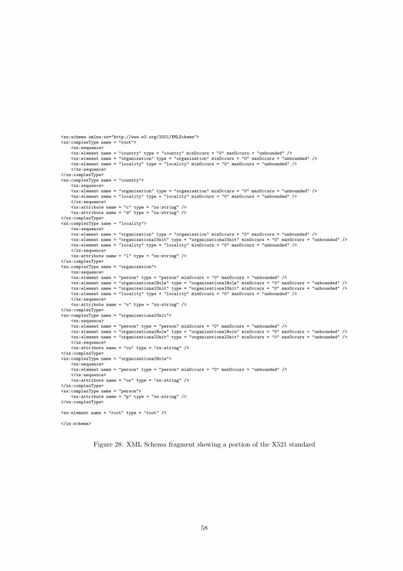
<xs:schema xmlns:xs="http://www.w3.org/2001/XMLSchema"><xs:complexType name = "root">
<xs:sequence><xs:element name = "country" type = "country" minOccurs = "0" maxOccurs = "unbounded" /><xs:element name = "organisation" type = "organisation" minOccurs = "0" maxOccurs = "unbounded" /><xs:element name = "locality" type = "locality" minOccurs = "0" maxOccurs = "unbounded" /></xs:sequence>
</xs:complexType><xs:complexType name = "country">
<xs:sequence><xs:element name = "organisation" type = "organisation" minOccurs = "0" maxOccurs = "unbounded" /><xs:element name = "locality" type = "locality" minOccurs = "0" maxOccurs = "unbounded" /></xs:sequence><xs:attribute name = "c" type = "xs:string" /><xs:attribute name = "d" type = "xs:string" />
</xs:complexType><xs:complexType name = "locality">
<xs:sequence><xs:element name = "organisation" type = "organisation" minOccurs = "0" maxOccurs = "unbounded" /><xs:element name = "organisationalUnit" type = "organisationalUnit" minOccurs = "0" maxOccurs = "unbounded" /><xs:element name = "locality" type = "locality" minOccurs = "0" maxOccurs = "unbounded" /></xs:sequence><xs:attribute name = "l" type = "xs:string" />
</xs:complexType><xs:complexType name = "organization">
<xs:sequence><xs:element name = "person" type = "person" minOccurs = "0" maxOccurs = "unbounded" /><xs:element name = "organisationalRole" type = "organisationalRole" minOccurs = "0" maxOccurs = "unbounded" /><xs:element name = "organisationalUnit" type = "organisationalUnit" minOccurs = "0" maxOccurs = "unbounded" /><xs:element name = "locality" type = "locality" minOccurs = "0" maxOccurs = "unbounded" /></xs:sequence><xs:attribute name = "o" type = "xs:string" />
</xs:complexType><xs:complexType name = "organisationalUnit">
<xs:sequence><xs:element name = "person" type = "person" minOccurs = "0" maxOccurs = "unbounded" /><xs:element name = "organisationalRole" type = "organisationalRole" minOccurs = "0" maxOccurs = "unbounded" /><xs:element name = "organisationalUnit" type = "organisationalUnit" minOccurs = "0" maxOccurs = "unbounded" /></xs:sequence><xs:attribute name = "ou" type = "xs:string" />
</xs:complexType><xs:complexType name = "organisationalRole">
<xs:sequence><xs:element name = "person" type = "person" minOccurs = "0" maxOccurs = "unbounded" /></xs:sequence><xs:attribute name = "or" type = "xs:string" />
</xs:complexType><xs:complexType name = "person">
<xs:attribute name = "p" type = "xs:string" /></xs:complexType>
<xs:element name = "root" type = "root" />
</xs:schema>
Figure 28: XML Schema fragment showing a portion of the X521 standard
58
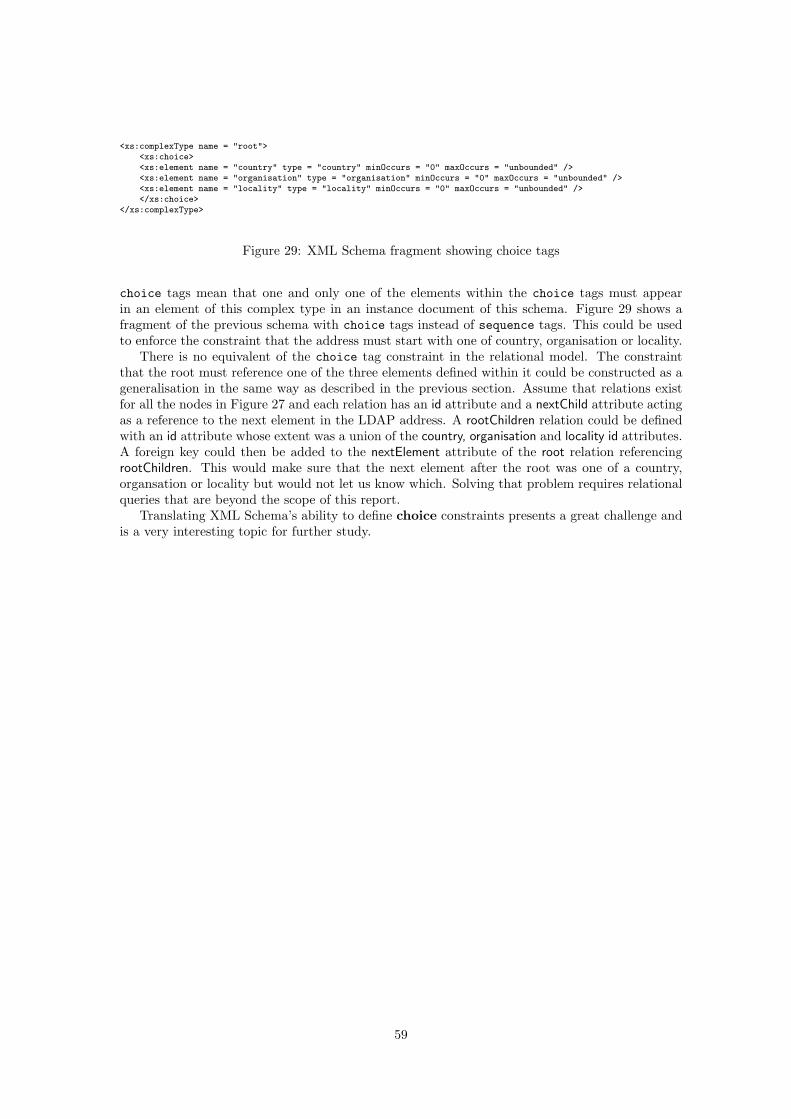
<xs:complexType name = "root"><xs:choice><xs:element name = "country" type = "country" minOccurs = "0" maxOccurs = "unbounded" /><xs:element name = "organisation" type = "organisation" minOccurs = "0" maxOccurs = "unbounded" /><xs:element name = "locality" type = "locality" minOccurs = "0" maxOccurs = "unbounded" /></xs:choice>
</xs:complexType>
Figure 29: XML Schema fragment showing choice tags
choice tags mean that one and only one of the elements within the choice tags must appearin an element of this complex type in an instance document of this schema. Figure 29 shows afragment of the previous schema with choice tags instead of sequence tags. This could be usedto enforce the constraint that the address must start with one of country, organisation or locality.
There is no equivalent of the choice tag constraint in the relational model. The constraintthat the root must reference one of the three elements defined within it could be constructed as ageneralisation in the same way as described in the previous section. Assume that relations existfor all the nodes in Figure 27 and each relation has an id attribute and a nextChild attribute actingas a reference to the next element in the LDAP address. A rootChildren relation could be definedwith an id attribute whose extent was a union of the country, organisation and locality id attributes.A foreign key could then be added to the nextElement attribute of the root relation referencingrootChildren. This would make sure that the next element after the root was one of a country,organsation or locality but would not let us know which. Solving that problem requires relationalqueries that are beyond the scope of this report.
Translating XML Schema’s ability to define choice constraints presents a great challenge andis a very interesting topic for further study.
59
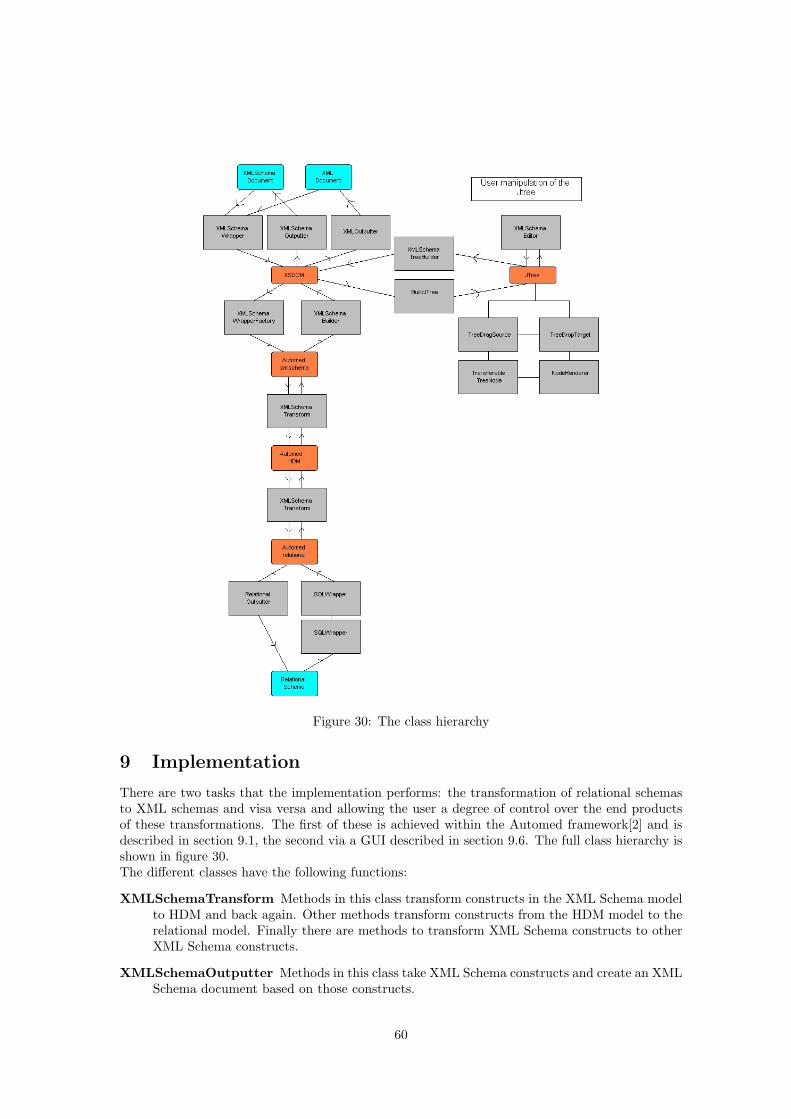
Figure 30: The class hierarchy
9 Implementation
There are two tasks that the implementation performs: the transformation of relational schemasto XML schemas and visa versa and allowing the user a degree of control over the end productsof these transformations. The first of these is achieved within the Automed framework[2] and isdescribed in section 9.1, the second via a GUI described in section 9.6. The full class hierarchy isshown in figure 30.The different classes have the following functions:
XMLSchemaTransform Methods in this class transform constructs in the XML Schema modelto HDM and back again. Other methods transform constructs from the HDM model to therelational model. Finally there are methods to transform XML Schema constructs to otherXML Schema constructs.
XMLSchemaOutputter Methods in this class take XML Schema constructs and create an XMLSchema document based on those constructs.
60
RelationalOutputter Methods in this class take SQL constructs and create a relational databasebased on them. They also transfer any data if the transformation was from an XML docu-ment rather than simply an XML Schema document.
BuildJTree Methods in this class convert the XSDOM representation of the schema documentto DefaultMutableTreeNode objects that can be displayed as a JTree. The other classes inthe tree branch of the API allow user manipulation of the JTree.
XMLSchemaBuilder Methods in this class convert the Automed XML Schema model into anXSDOM representation.
XMLSchemaTreeBuilder Methods in this class convert the JTree to XSDOM.
An XML document is transformed into a relational database as follows:
1. XMLSchemaWrapper converts the document to XSDOM
2. Optionally transforms can be done via the visual tool.
BuildJTree take the XSDOM and creates a JTree representation
The JTree can be manipulated
XMLSchemaTreeBuilder converts the JTree back to XSDOM
3. XMLSchemaWrapperFactory creates Automed SchemaObjects from the XSDOM
4. XMLSchemaTransforms transforms the XML Schema model to HDM and then to the SQLmodel.
5. RelationalOutputter creates the SQL tables and inserts any data if we were transformingan XML document.
A relational database schema is transformed into an XML instance document as follows:
1. SQLWrapper and SQLWrapperFactory convert the database in the Automed SQL model
2. XMLSchemaTranforms transforms the SQL model to HDM and then XML Schema
3. Optionally transforms can be done via the visual tool.
BuildJTree take the XSDOM and creates a JTree representation
The JTree can be manipulated
4. XMLSchemaOutputter creates the XML Schema document from the Automed XML Schemaconstructs and XMLOutputter generates an XML document conforming to the schema con-taining the data from the database.
9.1 Automed
The Automed framework supports the transformation and integration of schemas that are ex-pressed in different data modeling languages. To avoid the complications of using a chosen highlevel data model as the common data model Automed uses the HDM discussed in section 5. TheAutomed framework is implemented as a number of Java APIs [2].
A schema or data from virtually any source can be incorporated into the Automed frameworkby writing a wrapper for that data source. This is a java class that directly interrogates thedata source and then creates the necessary Automed Schema and SchemaObjects to represent thedata source in Automed. The design and implementation of a wrapper is discussed in detail insection9.3.
In Automed a schema is transformed by incrementally applying a set of primitive transforma-tions to it. This set of transformations forms the transformation pathway from the source schema
61
that we started with to a target schema. A key advantage of the Automed approach is that thetransformations and thus the transformation pathways are reversible. This is achieved by embed-ding the extent of the construct created or removed in each transformation. The extent defineshow data associated with the new or removed construct can be derived from other existing con-structs in the original schema. The reversibility of transformations enables automatic translationof queries posed on any schema on a given pathway into appropriate queries on a particular targetschema also on that pathway. This means that a schema created by an Automed wrapper can betransformed any number of times and a query on any schema on that transformation pathway willretrieve data from the original wrapped data source.
9.1.1 IQL
IQL [31] is a functional intermediate query language that can be used within the Automed frame-work to query any schema along a given transformation pathway. Queries posed on a targetschema are translated to a source schema that has been generated directly from a data source.Code within the wrapper for that data source then interrogates it directly to get a result. Allextent queries in Automed are expressed in IQL.
IQL supports a bag collection type and supports a number of predefined operators. See [31]for a detailed description of it’s capabilities.
9.2 Representing a Relational Schema in Automed
The SQLWrapper and SQLWrapperFactory[26] classes are used to create an Automed representationof a relational schema. The SQLWrapperFactory creates constructs that closely match those ofthe underlying database. For example the relational model relations and attributes are modeledas table and column constructs. I have use the SQL model as my representation of relationaldata in Automed. Two of the optional features I have used are the type of a column and whetheror not it is null-able.
9.3 The Automed XML Schema Wrapper
This is a new wrapper that allows XML documents constrained by an XML Schema or the XMLSchema document itself to be represented in Automed. A distinguishing feature of this wrapper isthat the extents of the schema objects can either be data items if an XML document is representedor types if only the XML Schema document is represented. The structure of the XML documentis constrained by the complex type and element definitions in the schema document and the datavalues are constrained by the simple types assigned to the elements or attributes. See section 2.3.2for a more detailed discussion of XML Schema.
The XML Schema wrapper is made up of two classes:
• The XMLSchemaWrapperFactory class that creates the Automed schema objects. This classalso contains methods to create the Automed XML Schema model constructs. See Section6 for a description of the constructs.
• The XMLSchemaWrapper class that establishes a connection to the XML Schema documentand creates an internal XSDOM representation of it.
See [26] for a detailed discussion about using the Automed API to create a wrapper.An outline of the algorithm to creates a representation of the XML Schema document in
Automed is given below. Details are given in the following sections:
1. Methods in the XMLSchemaWrapper class establish a connection to the specified XML Schemadocument.
2. When a connection has been established methods in XMLSchemaWrapper use the XMLSchema API[25] to extract the different components from the schema document. These
62
are used to create an internal XSDOM representation. See Section 9.5 for details aboutXSDOM and the translation process.
3. The internal XSDOM representation is used by the XMLSchemaWrapperFactory to populatethe Automed Schema.
9.4 The HDM transformations
All the transformations done by the XMLSchemaTransform class are via the HDM model. To allowthe XML Schema type information to be represented the HDM model is extended to add a typelabel to the node construct. It was decided to adopt this approach rather than go directly fromXML Schema to the SQL model to make the wrapper more general. Code has been written toconvert an XML Schema document into the basic HDM components of nodes, edges and con-straints. It should now be possible to easily transform these structures into the other data modelsthat Automed supports.
The transformations needed to go from HDM to the XML Schema model are described in thefollowing section. The transformations are done in two passes. The first transforms all the HDMparent nodes to XML Schema type constructs. In the second pass all the HDM child nodes aretransformed into XML Schema elements and the HDM edges linking the parent and child nodesare transformed into XML Schema complexTypeNest constructs. As with the transformationfrom XML Schema to the relational model the transformations are reversible so they are onlydescribed in the XML Schema to HDM direction. The transformations from the SQL model toand from HDM are not described in detail as they did form a core aspect of the project.
9.4.1 Transforming between XML Schema and HDM
Two optional labels have been added to the HDM node construct. The first for the type of thenode and the second for any boundedness constraints there might be.
• An HDM node is a parent if it appears as the second element in an HDM edge scheme. Forexample if there was an HDM edge scheme 〈〈 , shoe, colour〉〉 the 〈〈shoe〉〉 node would be aparent node.
• An element is a child if it appears as the third element in an HDM edge scheme. In theabove example 〈〈colour〉〉 would be a child node.
• The set of children-p of a particular parent (p) are all those child nodes that have the sameparent. For example in figure 18 the children are 〈〈shoeid〉〉 , 〈〈colour〉〉 and 〈〈price〉〉.
• An HDM node p is a grandparent if one of the children in children-p is a parent nodeitself.
The transformations to go from HDM to XML Schema are as follows:
1. Each HDM node representing an XML Schema element generates an attribute of the samename For each HDM parent node
addTypexs(〈〈xs:nodeName〉〉, 〈〈nodeName〉〉)
2. For each HDM child node represented by the HDM node and edge constructs:
〈〈nodeName, nodeType〉〉〈〈 , parentNode, nodeName〉〉an XML Schema element construct and a complexTypeNest construct linking the newXML Schema child element to it’s XML Schema parent type
addElemxs(〈〈xs:nodeName:nodeType〉〉)addCTNxs(〈〈 , xs:parentNode, xs:nodeName:nodeType〉〉)
63
are created.
If there is no type associated with the HDM node then an XML Schema element of typeanyType is created.
3. If there is a key or keyref constraint associated with an HDM edge
〈〈 , parentNode, childNode〉〉then an XML Schema attribute construct with scheme
addAttxs(〈〈xs:parentNode:childNode〉〉)is created.
This transformation is only valid if the HDM child node has a simple type associated withit.
4. If there is a key constraint associated with an HDM edge an XML Schema key constructwith scheme
addKeyxs(〈〈xs:keyName:parentNode:keyField〉〉)is created.
This transformation is only valid if the XML Schema attribute 〈〈xs:parentNode:keyField〉〉exists.
5. If an HDM edge links to two leaf nodes then an XML Schema keyref construct
addKeyRefxs(〈〈xs:keyrefName:parentType:refType : keyField〉〉)is created.
This transformation is only valid if XML Schema attribute constructs representing boththe HDM child nodes exist and there is an XML Schema key construct for the referencedtable.
The transformations are done in 3 passes:
1. All the HDM parent nodes are transformed in to XML Schema type constructs.
2. The HDM child nodes are transformed to XML Schema element and complexTypeNestconstructs.
3. Finally the XML Schema key and keyref constructs are added.
The transformations from XML Schema to HDM have an extra pass. In the final pass theXML Schema key constraints and nesting generate named HDM edges: pk for a key constraint,fk for a keyref and link for a nesting.
9.4.2 Transforming between HDM and SQL
HDM to SQL is also done in three passes similar to those described above. First the tables areadded then the columns are added to the tables and finally any primary or foreign key constraintsare added to the tables. When transforming from SQL to HDM the key constraints from SQLare not maintained. This is so the user can choose their own keys and nesting for the final XMLSchema in the GUI. Another reason this was done is that at the moment key constraints can onlybe added in the GUI, not removed. The key constraints may be maintain in the future as thefunctionality of the GUI improves.
9.5 XSDOM
As mentioned in Section 2.3.2 the XML Schema standard is very complex. To try and get awayfrom some of this complexity and to allow me to focus on those aspects of the XML Schemastandard that are most relevant to data storage and transformation I wrote the XSDOM classes.They are based on JDOM standard [16].
64
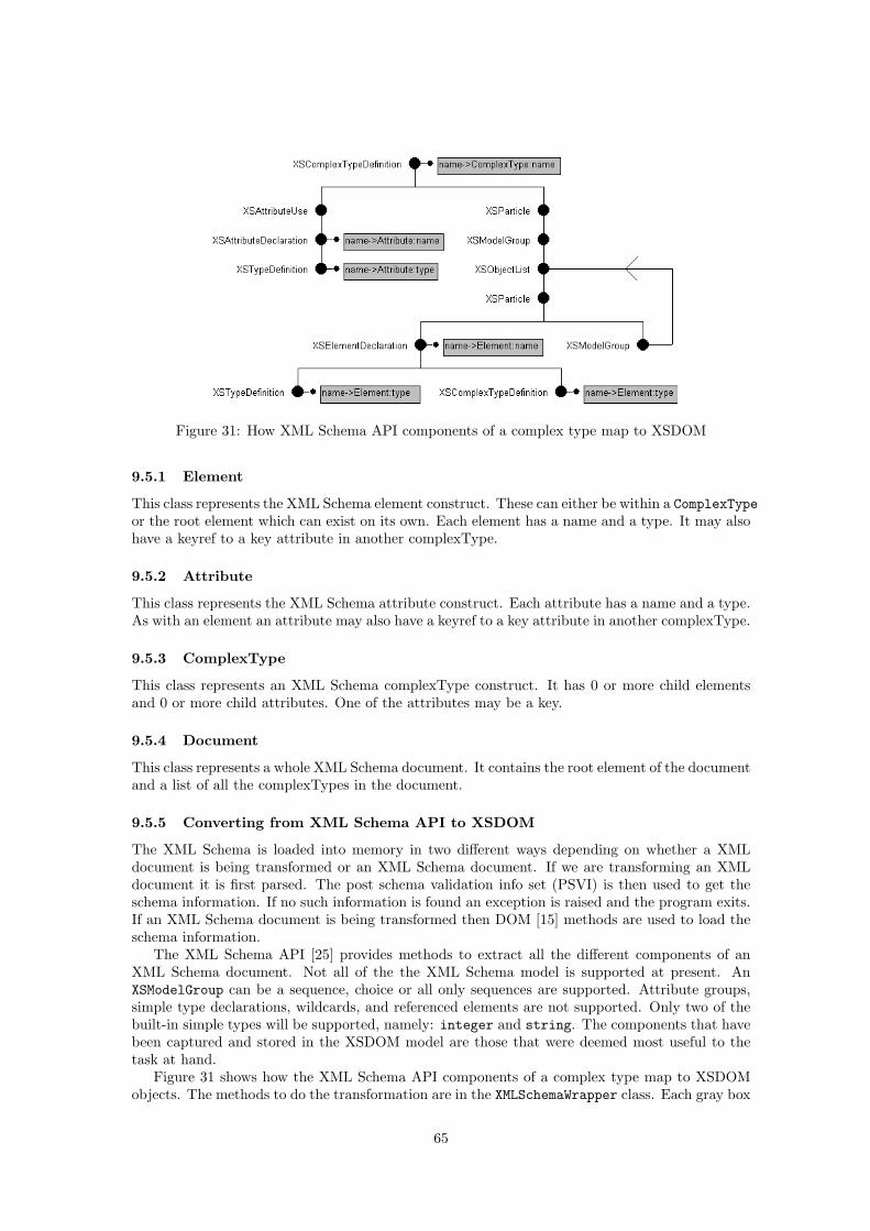
Figure 31: How XML Schema API components of a complex type map to XSDOM
9.5.1 Element
This class represents the XML Schema element construct. These can either be within a ComplexTypeor the root element which can exist on its own. Each element has a name and a type. It may alsohave a keyref to a key attribute in another complexType.
9.5.2 Attribute
This class represents the XML Schema attribute construct. Each attribute has a name and a type.As with an element an attribute may also have a keyref to a key attribute in another complexType.
9.5.3 ComplexType
This class represents an XML Schema complexType construct. It has 0 or more child elementsand 0 or more child attributes. One of the attributes may be a key.
9.5.4 Document
This class represents a whole XML Schema document. It contains the root element of the documentand a list of all the complexTypes in the document.
9.5.5 Converting from XML Schema API to XSDOM
The XML Schema is loaded into memory in two different ways depending on whether a XMLdocument is being transformed or an XML Schema document. If we are transforming an XMLdocument it is first parsed. The post schema validation info set (PSVI) is then used to get theschema information. If no such information is found an exception is raised and the program exits.If an XML Schema document is being transformed then DOM [15] methods are used to load theschema information.
The XML Schema API [25] provides methods to extract all the different components of anXML Schema document. Not all of the the XML Schema model is supported at present. AnXSModelGroup can be a sequence, choice or all only sequences are supported. Attribute groups,simple type declarations, wildcards, and referenced elements are not supported. Only two of thebuilt-in simple types will be supported, namely: integer and string. The components that havebeen captured and stored in the XSDOM model are those that were deemed most useful to thetask at hand.
Figure 31 shows how the XML Schema API components of a complex type map to XSDOMobjects. The methods to do the transformation are in the XMLSchemaWrapper class. Each gray box
65
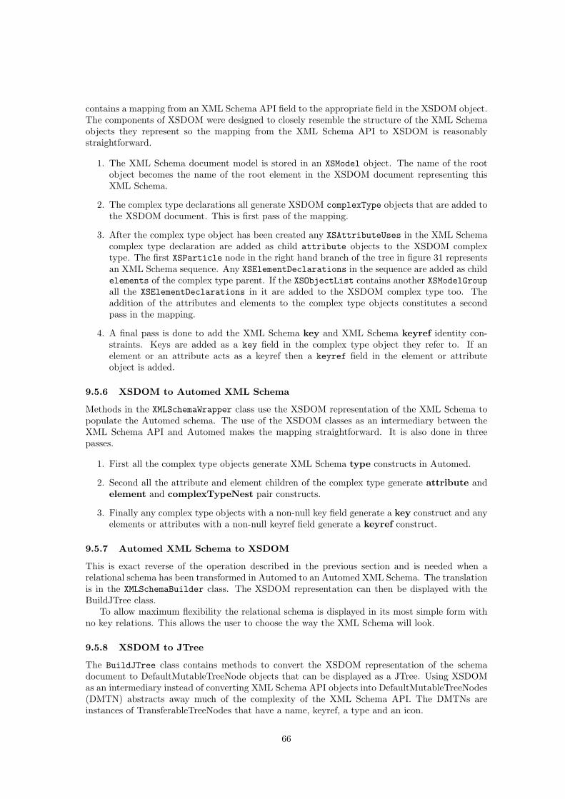
contains a mapping from an XML Schema API field to the appropriate field in the XSDOM object.The components of XSDOM were designed to closely resemble the structure of the XML Schemaobjects they represent so the mapping from the XML Schema API to XSDOM is reasonablystraightforward.
1. The XML Schema document model is stored in an XSModel object. The name of the rootobject becomes the name of the root element in the XSDOM document representing thisXML Schema.
2. The complex type declarations all generate XSDOM complexType objects that are added tothe XSDOM document. This is first pass of the mapping.
3. After the complex type object has been created any XSAttributeUses in the XML Schemacomplex type declaration are added as child attribute objects to the XSDOM complextype. The first XSParticle node in the right hand branch of the tree in figure 31 representsan XML Schema sequence. Any XSElementDeclarations in the sequence are added as childelements of the complex type parent. If the XSObjectList contains another XSModelGroupall the XSElementDeclarations in it are added to the XSDOM complex type too. Theaddition of the attributes and elements to the complex type objects constitutes a secondpass in the mapping.
4. A final pass is done to add the XML Schema key and XML Schema keyref identity con-straints. Keys are added as a key field in the complex type object they refer to. If anelement or an attribute acts as a keyref then a keyref field in the element or attributeobject is added.
9.5.6 XSDOM to Automed XML Schema
Methods in the XMLSchemaWrapper class use the XSDOM representation of the XML Schema topopulate the Automed schema. The use of the XSDOM classes as an intermediary between theXML Schema API and Automed makes the mapping straightforward. It is also done in threepasses.
1. First all the complex type objects generate XML Schema type constructs in Automed.
2. Second all the attribute and element children of the complex type generate attribute andelement and complexTypeNest pair constructs.
3. Finally any complex type objects with a non-null key field generate a key construct and anyelements or attributes with a non-null keyref field generate a keyref construct.
9.5.7 Automed XML Schema to XSDOM
This is exact reverse of the operation described in the previous section and is needed when arelational schema has been transformed in Automed to an Automed XML Schema. The translationis in the XMLSchemaBuilder class. The XSDOM representation can then be displayed with theBuildJTree class.
To allow maximum flexibility the relational schema is displayed in its most simple form withno key relations. This allows the user to choose the way the XML Schema will look.
9.5.8 XSDOM to JTree
The BuildJTree class contains methods to convert the XSDOM representation of the schemadocument to DefaultMutableTreeNode objects that can be displayed as a JTree. Using XSDOMas an intermediary instead of converting XML Schema API objects into DefaultMutableTreeNodes(DMTN) abstracts away much of the complexity of the XML Schema API. The DMTNs areinstances of TransferableTreeNodes that have a name, keyref, a type and an icon.
66
Figure 32: JTrees showing simple XML Schema transformations
The createJTree method creates a JTree representation of the XML Schema document. Fig-ure 32 is a series of screen shots showing how a simple schema can have keys and keyrefs addedto it. The left hand tree has no keys. The middle tree has had key constraints added to xsshoeidand xsmakeid. The right hand tree has had a keyref constraint added linking xsshoemakeid to thekey xsmymakes type: xsmakeid
9.6 GUI
The XMLSchemaEditor class is the main class for the GUI.
9.6.1 Operations in the GUI
There are a number of things one can do in the GUI. The formal transformations that are performedwhen these operations are done are described in the next section.
Firstly one can manipulate the schema. All the schema transformations are done on AutomedXML Schema constructs. Hopefully this can be expanded to work with HDM in the future:
Drag and Drop One complex type can be nested inside another one by dragging it over one ofthe elements in the new parent complex type.
Clicking the Transform menu item will bring up the following options:
Make key Selecting a child element on the JTree and then clicking Transform/Make Key willcreate an XML Schema key construct and will transform the child element into an XMLSchema attribute if it is an XML Schema element as all keys are defined to be attributes.The child icon will change.
Link This will create an XML Schema keyref construct. The element selected first will be madea key attribute so a key construct will be created for it.
XMLSchema to HDM Selecting this menu item will transform the JTree to HDM.
HDM to Relational Once an HDM representation of the schema has been created this menuitem will transform the HDM to the Automed relational model.
Clicking the Output menu item will bring up the following options. They are described in detailin Section 9.8:
Output Relational This will create a relational schema from the JTree.
Output XML Schema This will create an XML Schema document and an XML instance doc-ument from the JTree. This can be done any number of times so lots of different schemadocuments can be created.
67
9.7 Transformations in the GUI
A number of the operations in the GUI transform the XML Schema objects represented in theJTree. The basic operations can be used together to define composite transformations.
9.7.1 Drag and Drop
The drag and drop operation can be used to add or remove nesting. For the drag and drop toresult in a consistent model only a type object can be dragged and it must be dragged over anelement whose extent is the same as that of the type being dragged. At the moment drags anddrops are not checked for validity. This could be done in the future.
If for example a type object 〈〈xs:dragged〉〉 with parent type 〈〈xs:pd〉〉 is dragged onto a targetelement 〈〈xs:target :t〉〉 with parent 〈〈xs:pt〉〉 creating a new element 〈〈xs:new :dragged〉〉 we will havethe following composite transformation. If an element of type 〈〈xs:dragged〉〉 already existed inside〈〈xs:pd〉〉 it and the edge linking it to its parent are removed with two contract transformations.
addNestxs(〈〈dragged, pt, target〉〉)
The operations that make up this composite transformation are as follows:
addElemxs(〈〈xs:new :dragged〉〉, 〈〈xs:target :t〉〉)addCTNxs(〈〈 , xs:pt , xs:new :dragged〉〉, 〈〈 , xs:pt , xs:target :t〉〉)delCTNxs(〈〈 , xs:pt , xs:target :t〉〉, 〈〈 , xs:pt , xs:new :dragged〉〉)delElemxs(〈〈xs:target :t〉〉, 〈〈xs:new :dragged〉〉)contractCTNxs(〈〈 , xs:pd , xs:oldElement :dragged〉〉)contractElemxs(〈〈xs:oldElement :dragged〉〉)
9.7.2 Making an attribute a key
The transformation to make an attribute a with parent p a key called k is as follows:
addKeyxs(〈〈k, p, a〉〉)
9.7.3 Adding a keyref
The transformation to make an attribute a with parent p a keyref called kr referring to a key calledtf is as follows:
addKeyRefxs(〈〈kr, p, a, tf〉〉)
9.8 Materialising the Automed XML Schema
Methods in XMLSchemaTreeBuilder take the JTree nodes and convert them into an XSDOMrepresentation. Methods in the XMLSchemaOutputter class materialise the XSDOM.
Different classes of Automed XML Schema elements are defined below:
• An XML Schema element is a parent if it appears as the second element in a complexType-Nest scheme.
• A XML Schema element is a child if it appears as the third element in a complexTypeNestscheme.
• The set of children-p of a particular parent (p) are all those XML Schema child elementsthat have the same parent.
Rules to transform the Automed XML Schema model to an XML Schema document:
1. For an Automed schema called AM Schema an XML Schema element named AM Schemais created:
68
<element name="AM_Schema"><complexType><sequence>
<!-- Rest of the schema --></sequence></complexType>
</element>
2. For each parent element in an Automed XML Schema complexTypeNest construct anXML Schema complexType with name nodeName type is created:
<complexType name = "nodeName_type"><sequence>
<!-- child elements --></sequence>
</complexType>
3. For each Automed XML Schema child element linked to it’s parent by the a complex-TypeNest:
〈〈xs:elementName:elementType〉〉〈〈 , xs:parentType, xs:elementName:elementType〉〉
an XMLSchema element is created inside the element sequence of the XML Schema parentcomplexType:
<complexType name = "parentType"><sequence><element name = "elementName" type = "elementType" /><!-- Other child elements --></sequence>
</complexType>
4. For each Automed XML Schema attribute construct
〈〈xs:parentType:attributeName:attributeType〉〉an XML Schema attribute is created within the parentType:
<complexType name = "parentType"><!-- child element sequence --><attribute name = "attributeName" type = "attributeType" />
</complexType>
5. For each Automed XML Schema key construct
〈〈keyName, xs:parentType:keyField〉〉an XML Schema key element is created as shown below:
<key name = "keyName">
<selector xpath="<!-- XPath to the parent of keyField -->" />
<field xpath="@keyField" />
<key>
6. For each Automed XML Schema keyref construct
〈〈keyrefName, xs:parentType:refType:keyrefField〉〉〉an XML Schema keyref element is created as shown below:
69

<keyref name = "keyrefName" refers = "refType">
<selector xpath="<!-- XPath to the parent of keyrefField -->" />
<field xpath="@keyrefField" />
<key>
9.9 Creating SQL tables
The RelationalOutputter class converts constructs from the SQL model into relational tables.The algorithm is as follows:
1. Each table construct and any column constructs associated with that table
〈〈sql:tableName〉〉〈〈sql:tableName:columnName1 :columnType1 〉〉..〈〈sql:tableName:columnNamen:columnTypen〉〉
generate an SQL table:
CREATE TABLE tableName(columnName1 columnType1, ..., columnNamen columnTypen);
2. Once all the tables have been created any key constraints are added. Each primaryKeyconstruct
〈〈sql:tableName:keyColumn〉〉generates a primary key:
ALTER TABLE tableNameADD CONSTRAINT tableName_pk PRIMARY KEY (columnName);
3. Each foreignKey construct
〈〈sql:tableName:refTableName:keyColumn〉〉generates a foreign key:
ALTER TABLE tableNameADD CONSTRAINT tableName_fk
FOREIGN KEY (columnName) REFERENCES refTableName;
4. If the transformation was on an XML document then the relevant constructs are queriedusing IQL and SQL INSERT statements are issued to populate the new database.
As can be seen from the above once the Automed transformations have been done to createconstructs closely related to each model, actually materialising the model is not difficult.
70
10 Conclusions
Relational databases are the dominant data storage model and XML the de facto standard forsending information over the Internet. Being able to transfer data between the two formats hasbecome an important task. This project has presented a method of transferring data based ona low-level data modeling language thus abstracting away some of the differences between themodels and highlighting the similarities.
The first part of this report discussed the difficulties in the translation process and providedan overview of current approaches to the problem. Some examples of how XML has been stored inrelational databases were given and conversely examples were given of how relational data may beexported as XML. The advantages and disadvantages of the different approaches was discussed.
It was shown that having a good schema describing the XML aided the translation process.XML Schema was introduced as a widely accepted standard for describing these schemas.
A technique for creating an XML Schema document from a relational schema was presented.Two different approaches to creating a relational schema were also described. One that did notneed an XML Schema and one that did. It was shown that the latter resulted in a far moreefficient relational schema. The examples given throughout the report show that there are manydifferent ways of representing the same data in both XML and the relational model. Choosingthe most efficient is a very difficult task. Two automatic techniques were mentioned as well as thefact that some authors propose a level of user interaction in the choice.
The advantages of using a low-level language that to abstract away the differences betweenXML and RDBMSs was discussed HDM is one such language. A description was given as well asan example of how an XML document might be represented in the HDM.
Three major difficulties with the translation process were identified: transforming an XMLschema into a relational one and visa versa, providing some way of assessing the suitability ofthe transformed schema and providing a way of querying the new schema. These problems wereaddressed as follows:
10.1 Transforming the Schemas
The first task in transforming the schemas was to identify a way of describing them. For therelational model SQL DDL statements are the accepted and well understood way of doing this.Deciding which schema language to use to describe XML was more difficult. The first problemis that many XML documents exist that have no schema document describing them at all. Flo-rescu and Kossman’s edge schema for storing XML documents that have no constraining schemadocument was presented. Far more efficient and accurate transformations can achieved if thereis a schema. I decided to chose XML Schema as my schema language as it is powerful and is anaccepted W3C standard. It also has the advantage over the older DTDs that the schema itself isan XML document making it easier to parse and extract information from.
I took the decision to do the XML to relational transformations via the HDM, within theAutomed framework. This provided a number of advantages. Firstly using a low level abstractionof the data structures involved highlighted the differences and similarities between the two models.The graphical nature of the HDM further aided this. Another advantage of using HDM was thatthe relational model had already been described in terms of HDM structures. Related to thatnow that XML Schema has been described in terms of the simple HDM structures it should beeasy to transform the model into other models already described in terms of the HDM such asthe ER model. Finally Automed provided a sound theoretical basis for the transformations. On apractical level I was able to take advantage of the Automed APIs that already exist to create mydemonstration program and use the Automed editor to view them.
Using the HDM meant that the first task was to define XML Schema constructs in the HDMmodel, i.e. how could things like complex types be described in terms HDM nodes, edges andconstraints. Once this was done the primitive transformations on the XML Schema model weredefined. A few more complicated composite transformations within the model were also defined.As the projects main focus was transforming from XML to the relational model a complete set of
71
transformations was not presented. This may be a task for the future. To further help with thegeneralisation of the model transformations were defined from the XML Schema oriented structuresto general HDM oriented structures. These should be able to be used in transformations to anyor the models supported by Automed. In this instance they were transformed into relationaloriented structures. In practice this process involved writing an Automed wrapper to transformthe XML Schema document into Automed schema constructs and a number of transformationmethods using the Automed API. Once the relational oriented structures were created they wereused to build up SQL DDL statements that actually created the database. Using an intermediateCDM additionally helped made each step in the transformation process more manageable.
Going in the other direction I took advantage of the SQL wrapper already in Automed tocreate a schema of relational oriented constructs. These were then also transformed into moregeneral HDM oriented constructs and finally into XML Schema oriented constructs. The XMLSchema constructs were then used to create an XML Schema document.
Writing my program within the sound theoretical framework of the Automed system oftenhighlighted problems in my model as I realised that bits of my theory would not work in practice.This helped enormously in making my model more sound and consistent. If I had not had wellestablished theory behind the creation of my model and transformations I believe they would havebeen of far less value and much more likely to have contained errors.
10.2 Choosing the Most Appropriate Schema
To help with the task of choosing the most appropriate schema a visual tool was created presentingthe XML Schema document as a tree. This made it easy to see any nesting in the schema.Functionality was provided to allow a user to change the nesting of the schema by dragging anddropping nodes. Leaf nodes could also be turned into keys or keyrefs. Once the schema waswhat the user wanted it could be materialised as either an XML Schema or a relational database.The visualisation is XML Schema oriented. When translating from the relational model to XMLSchema the relational constructs were first transformed into XML Schema oriented ones beforebeing displayed in the tree.
10.3 Querying the Data
Another component of the Automed framework was used to move data between the two models.IQL was used to query the final schema along the transformation pathway. In this way XMLSchema oriented queries were used to extract the relational data and relational oriented queriesused to extract the XML data. The latter was done in two different ways. The visual tool allowedeither an XML document constrained by an XML Schema to be loaded or an XML Schemadocument on its own. If an XML document was loaded the data in it was used to populate therelational database. If an XML Schema document was loaded into the tool the database wasleft empty. Creating the XML representation of the relational data involved creating an XMLdocument conforming to the XML Schema already created and then populating the data elementsand attributes with data from the database.
10.4 Future work
The XML Schema standard is extremely comprehensive and only the subset of it thought mostrelevant to data storage was can be imported into Automed using the XML Schema wrapper.Hence many XML Schema documents cannot be imported. An obvious extension to this projectwould be to improve the XML Schema wrapper so that all XML Schema documents could beimported. Another drawback to the method proposed is that an XML document do be importedmust be constrained by an XML Schema. Zamboulis and Poulovassilis present a method forinferring a XML DataSource Schema from a XML document and importing that into Automed [33].A combination of their approach and the one presented here would be able to import any XMLdocument and be able to create an accurate an efficient model if an XML Schema did exist.
72
The transformations from XML Schema to relational model create a lot of relations: one foreach complex type, one for each unbounded element and one for each element of complex type.These could almost certainly be optimised in the future. A way of automatically transformingXML Schema elements that have choice associated with them, either as part of a key or using thechoice tags within a complex type was only discussed briefly. A more formal treatment of thisproblem is needed in the future.
Only a limited number of transformations on the XML Schema model were presented. Thesecould be expanded to include a set of all legal transformations on an XML Schema document.The model could then be used for restructuring XML Schema documents in a provably consistentfashion.
The visual tool was designed as a proof-of-concept and has a number of shortcomings thatcould be improved with more time. Operations cannot be reversed. At present there is no supportfor multi-value keys or XML namespaces. Operations are not checked for validity. In spite of theseshortcoming creating the tool within the Automed framework constantly highlighted problems inmy model as I went along and was an invaluable to the whole process.
73
References
[1] ALTOVA. xmlspy. http://www.xmlspy.com/, 2004.
[2] M. Boyd and N. Tong. The Automed repositories and API. Technical report, AutoMedProject, 2001.
[3] J. Liu C. Liu, M. Vincent and M. Guo. A virtual XML database engine for relationaldatabases. XSYM 2003, 2003.
[4] James Clark and Steve DeRose Eds. XML Path Language (XPath) Version 1.0.http://www.w3c.org/TR/xpath, November 1999.
[5] F. Chiu D. Lee, M. Mani and W. W. Chu. NeT & CoT: Translating relational schemas toXML schemas using semantic constraints. UCLA CS Technical Report, February 2002.
[6] C.J. Date. An introduction to Database Systems. Addison-Wesley Publishing Company, 1995.
[7] F. H. Lochovsky D.C. Tsichritzis. Data Base Management Systems. New York: AcademicPress, 1977.
[8] Jayavel Shanmugasundaram et al. Relational databases for querying XML documents: Lim-itations and opportunities. In VLDB Conference, 1999.
[9] Jayavel Shanmugasundaram et al. Efficiently publishing relational data as XML documents.VLDB Journal: Very Large Data Bases, 10(2–3):133–154, 2001.
[10] Jayavel Shanmugasundaram et al. A general techniques for querying XML documents usinga relational database system. SIGMOD Record, 30(3):20–26, 2001.
[11] L. Popa et al. Mapping XML and relational schemas with Clio.http://www.almaden.ibm.com/cs/clio/papers/icde02demo.pdf.
[12] M. Carey et al. XPERANTO: Middleware for publishing object-relational data as XMLdocuments. In VLDB Conference, pages 646–648, 2000.
[13] M. Wahl et al. Lightweight Directory Access Protocol (v3), RFC 2251.http://www.ietf.org/rfc/rfc2251.txt, December 1997.
[14] Phil Bohannon et al. From XML Schema to relations: A cost-based approach to XML storage.In Proc. of Intl. Conf. on Data Engineering (ICDE), 2002.
[15] Philippe Le Hgaret et al. Document Object Model (DOM). http://www.w3.org/DOM/, April2004.
[16] Brett McArthur et al. Eds. JDOM. http://www.jdom.org/, February 2004.
[17] Henry S. Thompson et al. Eds. XML Schema part 1: Structures.http://www.w3.org/TR/xmlschema-1, 2001.
[18] Scott Boag et al. Eds. XQuery 1.0: An XML Query Language. W3C Working Draft.http://www.w3c.org/TR/xquery, November 2003.
[19] Tim Bray et al. Eds. Extensible Markup Language (XML) Version 1.0 Third Edition.http://www.w3.org/TR/REC-xml, February 2003.
[20] D.C. Fallside. XML Schema part 0: Primer. http://www.w3.org/TR/xmlschema-0, 2001.
[21] Mary Ferandez, Wang-Chiew Tan, and Dan Suciu. Silkroute: Trading between relations andXML. In Proceedings of the Ninth International World Wide Web Conference, 2000.
74
[22] D. Florescu and D. Kossman. Storing and querying xml data using an RDBMS. Bulletin ofthe Technical Commitee on Data Engineering, 22(3):27–34, September 1999.
[23] Jonathan Gennick. SQL in, XML out. http://otn.oracle.com/oramag/oracle/03-may/o33xml.html, 2003.
[24] Kohsuke Kawaguchi. W3C XML Schema made simple.http://www.xml.com/pub/a/2001/06/06/schemasimple.html, June 2001.
[25] Elena Litani. XML Schema API. http://www.w3.org/Submission/xmlschema-api/, March2004.
[26] Peter McBrien. Automed in a nutshell. http://www.doc.ic.ac.uk/automed, 2004.
[27] Peter McBrien and Alexandra Poulovassilis. A general formal framework for schema trans-formation. In Data and Knowledge Engineering, volume 28, pages 47–71, 1998.
[28] Peter McBrien and Alexandra Poulovassilis. A uniform approach to inter-model transforma-tions. In Advanced Information Systems Engineering, volume 1626 of LNCS, pages 333–348.Springer Verlag, 1999.
[29] Peter McBrien and Alexandra Poulovassilis. A semantic approach to integrating XML andstructured data sources. In Advanced Information Systems Engineering, volume 2068 ofLNCS, pages 330–345. Springer Verlag, 2001.
[30] Dare Obasanjo. W3C XML Schema design patterns: Avoiding complexity.http://www.xml.com/pub/a/2002/11/20/schemas.html, November 2002.
[31] Alexandra Poulovassilis. The automed intermediate query language. Technical report, Au-toMed Project, 2001.
[32] International Telecommunication Recommendation. Recommendation x.521 (02/01) articlee21263. http://www.itu.int/rec/recommendation.asp?type=items&lang=e&parent=T-REC-X.521-200102-I, February 2001.
[33] Lucas Zamboulis and Alexandra Poulovassilis. XML data integration by graph restructuring.Technical report, 2003.
75


![FIVO/QSTORMAN SEMANTIC TOOLKIT FOR SUPPORTING DATA ... · X2R [15] for automating the process of translating legacy metadata descrip-tion from relational, LDAP or XML databases into](https://img.pdfslide.us/doc/110x75/6013fb7ecc71753df11761c0/fivoqstorman-semantic-toolkit-for-supporting-data-x2r-15-for-automating-the.jpg)