Embed Size (px)
Citation preview
TRANSISTOR RADIO
SERVICING MADE
EASY BY WAYNE LEMONS
volume explaining only what
you need to know to repair
transistor radios
at a profit.

Transistor Radio
Servicing
Made Easy
by Wayne Lemons
HOWARD W. SAMS & CO., INC.
$1.95
Cat. No. TRE-1
THE BOBBS-MERRILL COMPANY, INC. Indianapolis • New York

FIRST EDITION
FIRST PRINTING - MARCH, 1962
TRANSISTOR RADIO SERVICING MADE EASY
Copyright© 1962 by Howard W. Sams & Co., Inc., Indianapolis 6, Indiana. Printed in the United States of America.
Reproduction or use, without express permission, of editorial or pictorial content, in any manner, is prohibited. No patent liability is assumed with respect to the use of the information contained herein.
Library of Congress Catalog Card Number: 62-13499

Preface
This book was written to help you, the service technician, understand and repair the many transistor radios on the market today-at a profit. I cannot guarantee you'll be an expert after reading this book, but you will be in a much better position to become an expect.
When I first started to service transistor radios, I gave myself six months to become proficient enough to earn a profit. When the six months were up, I found I had been more optimistic than accurate. Even after nearly two years, I still come across new and puzzling problems. I can say, though, that I am making a good profit from transistor radio servicing. Naturally, I made mistakes, but I profited by them. Through this book, I hope you, too, will profit from what I have learned.
Only incidental theory is presented, as an adjunct to the thorough coverage of practical troubleshooting and repair techniques. Therefore, you will gain more from this book if you have a good background in radio theory.
The first part of this volume deals with practical transistor facts, derived from years of servicing experience. Since you need not be concerned with "holes," barrier levels, etc., in servicing, the explanations are confined to such factors as polarity, gain, biasing, impedance, and general operation. Also, as you will learn at the outset, there is quite a difference between pure theory and actual practice.
While studying this book, you will actually begin to solve many problems ( in your mind's eye) before you realize it. Once you have absorbed the contents, you will find you have all the knowledge necessary to service and repair any transistor radio on the market, and will be able to realize more profits from transistor radio servicing.

My thanks to Mr. H. S. King, Philco Corp., for information on "no-output-transformer" circuits; and Messrs. Briesacher, Martin, and DeAngio of General Supply Co., Waynesville, Mo., whose suggestions, hospitality, and facilities helped make this book possible.
w A YNE LEMONS
January, 1962

Contents
Chapter I
What You Should Know About Transistors Remembering Polarities-What the Ohmmeter and Circuit "see" -Gain versus Bias-How Rugged are Transistors?-Transistor Basing-Transistor Schematics
Chapter 2
Mixer-Oscillator Circuits Separate Oscillator-Troubleshooting-Causes of a Dead Oscillator - Antenna Circuit Troubles - Substituting Transistors -Checking an Antenna with a Grid-Dip Meter
Chapter 3
IF Circuits and Their Repair . Neutralization-Troubleshooting-Checking IF TransformersOther IF Circuits-Summary of IF Troubles
Chapter 4
Detector and AGC Circuits Transistor Detectors-Automatic Gain Control-Troubleshooting
Chapter 5
Servicing the Audio Stages Reflex Amplifiers-Output Amplifiers-Troubleshooting-Replacing Transistors
Chapter 6
Over-All Service Techniques . So Let's Repair a Radio-Intermittents
7
19
30
40
49
62

Chapter 7
Rapid Diagnosis and Repair In-Circuit Checking-The "Razor-Blade" Technique-How to Remove Parts from Printed Boards - Replacing Parts - Heat Sinks-Repairing Broken Boards
Chapter 8
Alignment and Tracking Dial Calibration-Pitfalls of Tracking-Alignment IndicatorsSealed Alignment Screws-How often are Alignment and Tracking needed?
Chapter 9
71
83
Repairing the "Weak" and "Not Quite Right" Radios 90 Signal Tracing-Audio Stage Gain-Is It the Design?-Hints on Improving Performance
Chapter 10
Noise, Oscillations, Squeals, and Motorboating Noise-Inherent Noise-Squeals, Oscillations, and Motorboating -Battery Electrolyte-Open Printed Circuits
Chapter 11
97
Tools and Equipment . 104 Equipment Needed-Schematics and Service Information-Parts Supplies
Chapter 12
Where to get Replacement Parts List of Parts Suppliers
Index .
. 114
. 123
CHAPTER I
What You Should Know
About Transistors
To become proficient in transistor circuit analysis there is nothing more important than starting to think in transistor terms. You have to know what a transistor consists of, the voltage polarities of its elements, and how your equipment "sees" the transistor.
Valence bonds, impurities, donor and acceptor atoms, and the like may make for noble conversation-but they won't help much in troubleshooting a circuit. You've been told that the current carriers inside the transistor are electrons in NPN types, and holes in PNP types. Don't let this apparent ambiguity disturb you, though. Imagine that they're electrons, lead pellets, or billiard balls-for service work, it really doesn't matter. You've never seen the current carriers ( electrons) in a vacuum tube, but chances are it hasn't disturbed you.
From a service standpoint, NPN and PNP types both work exactly alike, except that they require opposite workingvoltage polarities. If you reverse the leads of your voltmeter when going from a PNP to an NPN on a voltage check, you'd never know which type you were servicing. However, you do need to remember the names of the transistor elements. This isn't hard, especially if you are familiar with vacuum tubes. The emitter emits current carriers, just like the cathode of a vacuum tube; and the collector collects these carriers, just like the plate of a tube. Likewise, the base ( between the collector and emitter) controls the collector current ( and as a consequence, the emitter current), again much like the grid in a vacuum tube. But a transistor isn't a tube! So don't hold yourself too closely to tube analogy-it doesn't always work.
7
How does a transistor amplify? It is mainly a function of circuit impedance, or resistance transfer ( hence the name, transistor). As an example, the input of a common-emitter circuit is of fairly low impedance, while the output is fairly high. Therefore, the transistor amplifies because it has the ability to transfer the current from the low-resistance ( impedance) input into the high resistance of the output with very little loss. It follows, then, that if the same amount of current flows in the high-impedance circuit as does in the low-impedance circuit, there will be a greater voltage drop across the high impedance. For example, if 1 milliamp flows in an input circuit with an impedance of 500 ohms, there would be a 0.5-volt drop. If that same 1 milliamp were transferred ( assuming no losses in the transistor) to a 10,000-ohm output impedance, the voltage drop would be 10 volts-or, in other words, a gain of 20 volts in the circuit. This is as far as we will go into transistor theory. However, what is important, for service work, is that transistors do have gain. In them, a current change produces a power change; whereas in a tube, a voltage change produces a power change. Incidentally, low-impedance devices are known as current devices.
REMEMBERING POLARITIES
Since there are two basic types of transistors, the PNP and the NPN, how does one remember what the polarity of applied voltage is in each type? The key is the middle letter, which actually designates the transistor type. If the P is in the middle ( as in NPN ) , you know two things: first, the collector voltage is positive with respect to the emitter; and second, when correctly biased, the base voltage is also ( a fraction of a volt) more positive than the emitter. On the other hand, if the middle letter is an N ( as in PNP), then the collector and base voltages are negative. Remember that the base of a transistor is always biased in the same polarity as the collector. This is opposite to tube polarity, where the grid is usually negative with respect to the plate, which is positive.
Small-signal transistors ( those used in RF and IF stages) usually have about a 0.1- to 0.3-volt bias, in order to produce 8
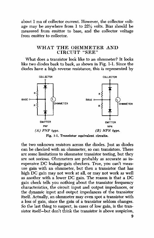
about 1 ma of collector current. However, the collector voltage may be anywhere from 1 to 22½ volts. Bias should be measured from emitter to base, and the collector voltage from emitter to collector.
WHAT THE OHMMETER AND CIRCUIT "SEE"
What does a transistor look like to an ohmmeter? It looks like two diodes back to back, as shown in Fig. 1-1. Since the diodes have a high reverse resistance, this is represented by
COLLECTOR
EMITTER
PNP
\ OHMMETER
(A) PNP type.
COLLECTOR
EMITTER
NPN
\ OHMMETER
(B) NPN type.
Fig. 1-1. Transistor equivalent circuits.
the two unknown resistors across the diodes. Just as diodes can be checked with an ohmmeter, so can transistors. There are some limitations to ohmmeter transistor testing, but they are not serious. Ohmmeters are probably as accurate as inexpensive DC leakage-gain checkers. True, you can't measure gain with an ohmmeter, but then a transistor that has high DC gain may not work at all, or may not work as well as another with a lower DC gain. The reason is that a DC gain check tells you nothing about the transistor frequency characteristics, the circuit input and output impedances, or the dynamic input and output impedances of the transistor itself. Actually, an ohmmeter may even spot a transistor with a loss of gain, since the gain of a transistor seldom changes. So the last thing to suspect, in cases of low gain, is the transistor itself-but don't think the transistor is above suspicion,
9

for despite whatever you may have heard or read, transistors do fail, and with rather surprising regularity!
Fig. 1-2 shows how to make the ohmmeter test. Place the red lead on the base, touch the collector with the black lead, and note the reading. Now touch the black lead to the emitter and again note the reading. If the base-to-collector reading is low, then the base-to-emitter reading should also be
BLACK RED Q
Fig. 1-2. Transistor testing with an ohmmeter.
low. Likewise, if the former is high, then the latter should also be high. Now move the black lead to the base. Touch the red lead to the collector and note the reading, and then touch it to the emitter and again note the reading. These two readings should be the opposite of the first two. For instance, if the first two readings showed a low resistance, the last two should read high, and vice versa. 10

Now measure the resistance between the collector and emitter. Surprisingly, here is where most transistor shorts occur; usually the diode action between base and collector and between base and emitter is unaffected. Fig. 1-3 shows how the emitter-collector short evidently occurs. Excessive current punctures a hole in the base by melting its material. At the same time, the melted material physically connects the emitter and collector together. While there is no short
C
SHORT
BASE B
E
( A) Physical short. (B) Equivalent circuit.
Fig. 1-3. Collector-to-emitter short.
between the base and either the emitter or collector, there is actually a short between the emitter and collector. This can happen because the base is so thin that it literally is disintegrated around the area of the leakage path between the emitter and collector, as shown in Fig. 1-3.
GAIN VERSUS BIAS
Unlike in RF and IF vacuum tubes, the gain of a transistor does not change drastically as the bias voltage changes. However, within certain limits, the collector current does change, and yet the gain of the circuit may remain fairly constant. ( If you doubt this, try testing a transistor on a dynamic AC checker that has a bias-change provision.) This is why the special AGC circuits discussed in Chapter 4 are necessary. Only at the critical values of bias near cutoff and saturation is the gain affected to any great extent by
11

bias changes. If, then, you find a transistor with a bias ( emitter to base) of 0.1 volt, don't be disturbed even though the service information may show 0.15 or 0.2 volt. As long as the base has the same polarity as the collector and between a 0.1- and 0.3-volt difference with respect to the emitter, it is most likely correct. As an example, the converter stage does not always appear to have the correct bias. The bias may be zero, only very slightly forward, or even reversed. This is normal, since the oscillator sine-wave voltage drives the converter into conduction on each positive ( negative, depending on the transistor type) excursion.
HOW RUGGED ARE TRANSISTORS?
A common misconception, fostered from the early days of transistors, is that transistors must be handled with kid gloves. All sorts of precautions have been given wide publicity. Don't worry too much about transistors, though. Chances are you won't ever burn one out if, say, you don't use a heat sink. The fact is, in some sets you can't even get to the transistor leads to apply a heat sink. You can-and should-use a soldering iron of about 75 watts, especially when removing parts, including transistors, from the board. You'll read more about this in Chapter 7.
A transistor can be checked with just about any service ohmmeter and never be damaged. The battery voltage of the ohmmeter is unimportant if the meter movement is sufficiently sensitive. In fact, you can apply 500 volts across a transistor-as long as you use a suitable resistance in series with it to reduce the current to a milliamp or so. Transistors are used every day in just such circuits, and the series resistance in any standard ohmmeter will limit the current to a safe value while they are being checked.
You can accidentally reverse the battery polarity on a transistor radio and probably not damage a single transistor. You may damage an electrolytic, but only if the radio were left on for quite a while.
You can heat the case of some transistors to the point where you can't touch them without burning yourself, and they will likely go right on working-or, if they quit operating, they will again work normally after permitted to cool. 12

You can increase the reverse voltage on a transistor until it "zeners" ( breaks down in the reverse direction) and, unless the current is excessive, the transistor will probably be all right when the voltage is removed.
With anything so rugged, you might wonder if they ever fail. Of course they do! They open-that is, the element separates from its external lead. They short between any two elements, but usually between emitter and collector. They develop leakage, one of the hardest troubles to diagnose either in or out of the circuit. Two identical transistors will not display the same amount of leakage. Even in a single transistor, leakage can vary, and usually does with heat and applied voltage. For this reason, a transistor may check "good" in a leakage tester or with an ohmmeter, yet not work in the circuit. Transistors in a circuit may have as much as 9 volts ( or more) on the collector, while most testers use only 4½ volts for testing. A transistor can perform perfectly with 4½ volts and refuse to work with 5 volts. You'll learn more, in later chapters, about how to spot this trouble.
TRANSISTOR BASING
Above all, memorize the base-lead layouts of transistors. This isn't hard to do, and it will provide you with the key for all transistor circuit tracing. Tube printed circuits have sockets as landmarks, but in transistor radios you'll seldom find a transistor socket. You must know the position of the leads! Just about every radio you'll encounter will have one of the four basic base layouts shown in Fig. 1-4. Remember these two rules:
1. The base lead is always between the emitter and collector.
2. The collector lead is marked by either a color dot or line, or is set off by itself ( Fig. l-4A).
Probably the most common base layout today is the "top hat" design shown in Fig. l-4B. You can remember this arrangement more easily from the familiar schematic symbol. Hold the transistor leads so they point toward you, with the base (middle) lead to the left. The connections will then
13
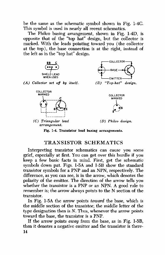
be the same as the schematic symbol shown in Fig. l-4C. This symbol is used in nearly all recent schematics.
The Philco basing arrangement, shown in Fig. l-4D, is opposite that of the "top hat" design, but the collector is marked. With the leads pointing toward you ( the collector at the top), the base connection is at the right, instead of the left as in the "top hat" design.
~ SHIELD LEAD
WHEN USED
( A) Collector set off by itself.
COLLECTOR
"6~---17\ : : B~E L-+----J :
I _________ I
cec:~::~ ~EMITT~
(B) "Top-hat" design.
COLLECTOR
"6: E
( C) Triangular lead ( D) Philco design. arrangement.
Fig. 1-4. Transistor lead basing arrangements.
TRANSISTOR SCHEMATICS
Interpreting transistor schematics can cause you some grief, especially at first. You can get over this hurdle if you keep a few basic facts in mind. First, get the schematic symbols down pat. Figs. l-5A and l-5B show the standard transistor symbols for a PNP and an NPN, respectively. The difference, as you can see, is in the arrow, which denotes the polarity of the emitter. The direction of the arrow tells you whether the transistor is a PNP or an NPN. A good rule to remember is; the arrow always points to the N section of the transistor.
In Fig. l-5A the arrow points toward the base, which is the middle section of the transistor; the middle letter of the type designation then is N. Thus, whenever the arrow points toward the base, the transistor is a PNP.
If the arrow points away from the base, as in Fig. l-5B, then it denotes a negative emitter and the transistor is there-14
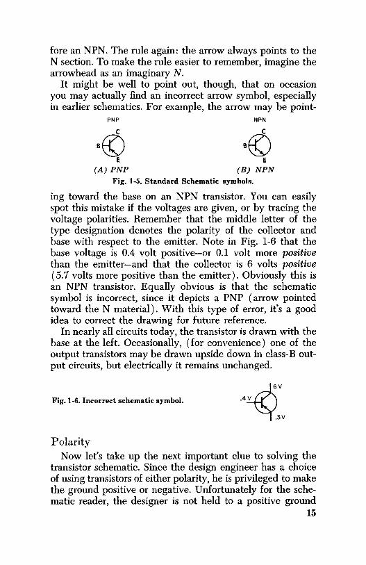
fore an NPN. The rule again: the arrow always points to the N section. To make the rule easier to remember, imagine the arrowhead as an imaginary N.
It might be well to point out, though, that on occasion you may actually find an incorrect arrow symbol, especially in earlier schematics. For example, the arrow may be point-
PNP
B© E
(A) PNP
NPN
B© E
(B) NPN
Fig. 1-5. Standard Schematic symbols.
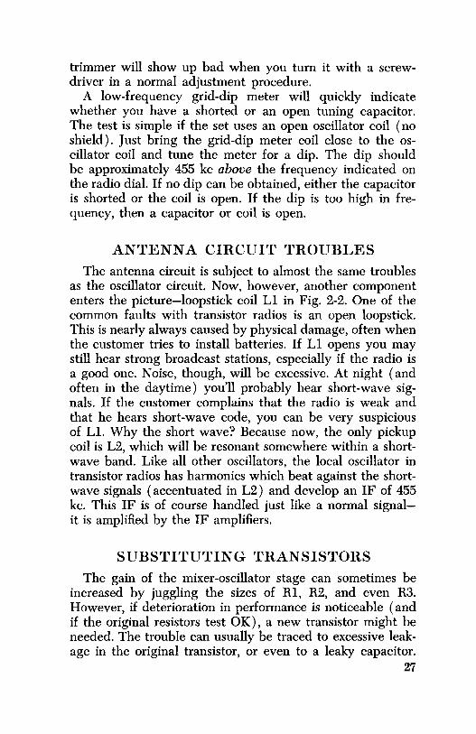
ing toward the base on an NPN transistor. You can easily spot this mistake if the voltages are given, or by tracing the voltage polarities. Remember that the middle letter of the type designation denotes the polarity of the collector and base with respect to the emitter. Note in Fig. 1-6 that the base voltage is 0.4 volt positive-or 0.1 volt more positive than the emitter-and that the collector is 6 volts positive (5.7 volts more positive than the emitter). Obviously this is an NPN transistor. Equally obvious is that the schematic symbol is incorrect, since it depicts a PNP ( arrow pointed toward the N material). With this type of error, it's a good idea to correct the drawing for future reference.
In nearly all circuits today, the transistor is drawn with the base at the left. Occasionally, ( for convenience) one of the output transistors may be drawn upside down in class-Boutput circuits, but electrically it remains unchanged.
Fig. 1-6. Incorrect schematic symbol.
Polarity
Now let's take up the next important clue to solving the transistor schematic. Since the design engineer has a choice of using transistors of either polarity, he is privileged to make the ground positive or negative. Unfortunately for the schematic reader, the designer is not held to a positive ground
15

for PNP's or a negative ground for NPN's-the ground may be positive or negative with either type. Moreover, some of the transistors in a single radio may be NPN's and others PNP's.
Fig. 1-7 shows two typical PNP transistor circuits. In Fig. l-7A, the positive side of the battery is grounded; the negative side supplies the proper polarity to the collector and base. Fig. l-7B shows a circuit with the same transistor and parts, and yet the negative side of the battery supply is grounded. There is certainly nothing wrong with this circuit, since the negative side is still tied to the collector. The emitter, which was grounded in Fig. 1-7 A, is tied to the positive
0
2 "'
n +
( A) Positive ground.
IOK
g "' "'
- 30 MFD
n +
(B) Negative ground.
Fig. 1-7. PNP circuits with reversed polarities.
side of the battery in Fig. l-7B. Bias is still supplied in exactly the same proportion from ground.
Fig. 1-8 shows the same circuits as Fig. 1-7 except that NPN transistors are used instead of PNP' s. Notice that the battery polarities are reversed from those in Fig. 1-7. Otherwise the circuit performance is identical to that of Fig. 1-7.
Fig. 1-9 shows how a designer might use both a PNP and NPN transistor in consecutive circuits. It's all a matter of polarities between the emitter, base, and collector. In this example, the NPN emitter bypass is returned to groundbut it could have been tied to the negative line if more convenient. It seems that most designers return their bypasses to ground, but this does not change the operation of the circuit in any way. It does, though, make for some peculi-16

arities in the polarity of electrolytics. Look again at the basecircuit electrolytic bypass. The negative side of the bypass is connected to the base, but an NPN ( remember the rule) has a positive base-but only with respect to the emitter, however, not necessarily positive with respect to ground.
+
+
+
+ +
(A) Negative ground. (B) Positive ground.
Fig. 1-8. NPN circuits with reversed polarities.
In this circuit, if you measured the base with respect to ground, you would find it negative by about 5.5 volts. Now if you measured from base to emitter, you would find the base more positive than the emitter by 0.1 volt, just as it should be. The collector is zero volts with respect to ground, but measured from the emitter it is 5.6 volts positive.
Voltage Readings Voltage given on schematics are nearly always taken with
respect to ground (common). This makes it pretty hard to measure the bias voltage on the NPN transistor in Fig. 1-9, since there is such a little difference between 5.6 volts and 5.5 volts. The recommended procedure, at least at the beginning, is to measure bias voltages on a low-range scale of your meter, between base and emitter, making sure the polarity is correct.
Measuring Transistor Current Sometimes you may want to know how much current a
particular transistor is drawing. The easiest way is to meas-17

6Vn-+
Fig. 1-9. Circuit using both a PNP and NPN from a common power source.
ure the voltage drop across the emitter resistor and calculate the current from Ohm's law. If there is no emitter resistor, measure the voltage across the collector resistor instead. Most RF, IF, and mixer-oscillator transistors will be biased to draw about 0.7 to 1.5 milliamperes.
18

CHAPTER 2
Mixer-Oscillator Circuits
The mixer-oscillator is usually the first stage in transistor radios, although several late-model radios have an RF stage ahead of it. The mixer-oscillator performs three functions: It generates a local-oscillator signal, mixes that signal with the incoming RF, and then amplifies the resultant beat between these two frequencies. This beat is the IF frequency.
As with tube mixers, a transistor must be biased as a detector, or nonlinear amplifier. In tube circuits this bias is generally provided by the negative voltage drop across the oscillator grid resistor, as shown in Fig. 2-1. In transistor circuits, however, no such high impedance exists, so the bias is supplied by inserting a lK to 5K resistor in the emitter lead of the transistor.
In tube circuits it is common practice to check for oscillations by simply reading the oscillator grid voltage. If the voltage is negative by more than two or three volts, it is a pretty sure sign that the oscillator is working. No such simple test can be made on transistor oscillators, however. True, some voltage is developed when the transistor oscillates, but the amount is so small that it is impossible to tell whether it is caused by normal bias conditions or by oscillations. There are, though, a couple of ways you can tell whether the oscillator is working. Place your meter on a low-voltage scale and measure the bias voltage between the emitter and base. The exact amount of this voltage is not too important. ( Depending on the circuit design, the voltage may be such that the transistor is slightly forward-biased, near zero, or even
19

reversed-biased.) Now, while monitoring the bias, turn the radio tuning dial from one end of the band to the other. If the oscillator is working, the bias voltage will change as you move the dial. Another way to check bias is to short out the oscillator section of the tuning capacitor as you monitor the voltage. The bias voltage should change noticeably when you do this. A caution here, though-in some circuit designs, the tuning-capacitor stator is tied directly through the oscillator coil to the supply voltage. In this case, shorting the capacitor may result in damage to the coil and you won't know whether the circuit is oscillating or not.
NEG VOLTAGE
B+
Fig. 2-1. Method of developing bias of oscillator grid.
The actual circuit used in transistor radios where one transistor does both the oscillating and mixing is known as a modified autodyne. An autodyne utilizes the elements of the transistor so that they do double duty as both a mixer and local oscillator.
Fig. 2-2 shows the circuit function. Here, energy from oscillator tank coil L3 is fed through C2 back to the emitter, and energy from the collector circuit is coupled through L4 to sustain oscillations. Both C3 and C4 are collector-current bypasses for the oscillator, and Cl is the base bypass. Emitter resistor R3 has a twofold purpose: it presents an impedance to prevent the feedback voltage from being grounded, and it develops voltage to keep the transistor biased near cutoff.
Ll-L2 is the loopstick antenna. L2 has only a few turns which match the high impedance of Ll to the low impedance of the transistor base circuit.
Some oscillator circuits use base instead of emitter feedback as shown in Fig. 2-3. Notice the similarity to the circuit 20

@
QJ® MIXER /OSCILLATOR
PNP
@ @ q)®
@
@
Fig. 2-2. Collector-to-emitter feedback.
C TOIF
TRANSISTOR
+
in Fig. 2-2, except that now the feedback voltage goes to the base through Cl instead of to the emitter through C2. The primary terminals of oscillator coil L4 are reversed to provide the correct feedback phase; otherwise the circuits are
MIXER/OSCILLATOR
PNP
@ qJ® @ C
@ @
+
Fig. 2-3. Collector-to-base feedback. 21

identical. Both circuits use the same bias and emitter resistors, the same size of bypass capacitors for Cl and C2, and the same transistor.
All other mixer-oscillator circuits are variations of these two. Fig. 2-4 shows a circuit using a three winding transformer, but in reality it is no different from the one in Fig. 2-2. L5 is used for the emitter pickup rather than for tapping the tank coil as in the first two circuits.
Fig. 2-5 might at first appear to be different but it also closely resembles the basic circuit of Fig. 2-3. In Fig. 2-5 the feedback is from the collector to the base through L4 and Cl. The tap on L3 now becomes the collector feedback winding. The IF transformer is connected directly to the collector and
Fig. 2-4. Isolated-coil feedback.
is in series with part of the oscillator coil. In most circuits the oscillator coil is connected to the collector and the IF to the power source. Except for some special diode AGC circuits, it makes no difference whether the oscillator coil or the IF is connected to the collector.
Note in this circuit that base bias resistor Rl is not used; the designer depends on the reverse leakage of the transistor to act as Rl. This could make the circuit a little more critical if you have to change transistors. In such case you might have to juggle the value of R2 somewhat to arrive at optimum performance. 22

@ ®~
- +
MIXER /OSCILLATOR PNP ----
Fig. 2-5. Collector-to-base feedback.
SEPARATE OSCILLATOR
Fig. 2-6 shows a configuration using a separate oscillator transistor. Essentially this is the same kind of configuration used in the autodyne circuit. Feedback is to the base, and the oscillator voltage is injected ( through a .05-mfd. capacitor) into the mixer from a tap on the oscillator coil.
TROUBLESHOOTING You have already learned a couple of ways of telling
whether the oscillator is working or not. Another way is to bring an operating radio close to the dead radio. Place one dial near the center of the broadcast band. Now sweep the other dial through its range until you hear ( or don't hear) a beat (whistle). If you do hear a beat, then it is obvious that both oscillators are functioning.
A tuned signal tracer is an ideal instrument for checking the oscillator. It will tell not only whether the stage is working or not, but also at what frequency. A high-impedance earphone plugged into a low-frequency grid-dip oscillator
23

( GDO) will let you hear the beat between the GDO and the radio oscillator when both are tuned to the same frequency (Fig. 2-7). Remember, the radio oscillator should be at the IF frequency-usually 455 kc above the dial reading. For example, if the radio dial is set to 1000 kc, you should hear the beat near 1455 kc on the GDO. If the radio is operating from the front-end on ( that is, you are able to hear noise through
I00K
MIXER NPN ----
4.7K
.001
I0K
E
470
Fig. 2-6. Separate oscillator and mixer circuits.
the radio, but no stations), chances are the oscillator is not operating. You can usually confirm this suspicion by simply bringing the suspected radio near a fluorescent lamp or other noise source. Now tum the oscillator slug; if the noise becomes maximum as you do, the oscillator is working. If there is no change, then the oscillator isn't working ( or the antenna circuit may be defective).
Together with conventional troubleshooting methods, a low-range AC voltmeter or a wide-band oscilloscope will also 24

indicate whether the oscillator is working, although of course neither will tell you whether at the correct frequency.
CAUSES OF A DEAD OSCILLATOR
Probably the most common cause of oscillator failure is an open antenna base coil. In any of the circuits except that of Fig. 2-6. if antenna base coil L2 is open, the oscillator will not work. In Fig. 2-2, for example, if L2 opens there will be no base bypass through Cl, and so no oscillations. In Fig. 2-3 there would be no feedback to the base if L2 opened.
Fig. 2-7. Using a grid-dip oscillator to check the radio oscillator.
The second most common cause of oscillator failure is probably the transistor itself. Unfortunately, there aren't too many ways, short of substitution, to check an oscillator-mixer transistor. Without removing the transistor from the circuit, you can make a rough check with an ohmmeter for diode action, as explained in Chapter 1. Because there are a number of shunt current paths, the resistance will not be high in the reverse direction, but should be higher than in the forward direction. If this test fails to show the transistor bad,
25

it is best to make a quick check of other possible troubles before changing the transistor.
Capacitors Cl, C2, and C4 are common offenders. One of them might be open ( sometimes caused by physical damage). Also, it is not too uncommon for one of them to develop leakage or even a short. Fortunately, when these capacitors do develop leakage, there is usually noise, somewhat like static, in the radio. Therefore, if you hear such a noise you can usually suspect a leaky capacitor. Later in the book there is a section presented on how to isolate the noise to a particular stage.
The capacitor across the primary of the IF transformer, is another troublemaker. Since it is the oscillator collector bypass, it's presence is essential-not only for this purpose, but for tuning to the IF as well. Most radios will start squealing when this capacitor opens. But sometimes the radio will just die a natural death, with no complaints except maybe squealing at one end of the dial.
An open capacitor can best be checked by simply shunting a good one across it. Leaking or shorted capacitors, in addition to creating random noise as noted previously, will nearly always affect the bias. Capacitors in transistor radios are rated at low voltages and for this reason should never be tested for leakage with more than 25 volts. One good way to check a suspected capacitor, such as Cl in Fig. 2-2, is to measure the voltage at the junction of Rl and R2. If it seems low, disconnect Cl at one end. If the voltage increases, the capacitor should be replaced.
A shorted or leaky tuning or trimmer capacitor can often be a "dog," since they seldom go bad. But these little transistor-radio capacitors are not nearly so rugged as their tuberadio counterparts. Like any other capacitor, they open, leak, and short. To check for the last two, put an ohmmeter across the capacitor terminals. In most circuits you'll read the oscillator ( or antenna) coil resistance of 8 to 10 ohms. Leave the ohmmeter leads connected and move the tuning capacitor back and forth through its complete range. Any variation, however slight, in the ohmmeter reading, indicates leakage. If you suspect the trimmer, you almost have to disconnect the coil from the tuning capacitor and then check the trimmer with an ohmmeter. However, it is possible that the 26
trimmer will show up bad when you tum it with a screwdriver in a normal adjustment procedure.
A low-frequency grid-dip meter will quickly indicate whether you have a shorted or an open tuning capacitor. The test is simple if the set uses an open oscillator coil ( no shield). Just bring the grid-dip meter coil close to the oscillator coil and tune the meter for a dip. The dip should be approximately 455 kc above the frequency indicated on the radio dial. If no dip can be obtained, either the capacitor is shorted or the coil is open. If the dip is too high in frequency, then a capacitor or coil is open.
ANTENNA CIRCUIT TROUBLES
The antenna circuit is subject to almost the same troubles as the oscillator circuit. Now, however, another component enters the picture-loopstick coil Ll in Fig. 2-2. One of the common faults with transistor radios is an open loopstick. This is nearly always caused by physical damage, often when the customer tries to install batteries. If Ll opens you may still hear strong broadcast stations, especially if the radio is a good one. Noise, though, will be excessive. At night ( and often in the daytime) you'll probably hear short-wave signals. If the customer complains that the radio is weak and that he hears short-wave code, you can be very suspicious of LL Why the short wave? Because now, the only pickup coil is L2, which will be resonant somewhere within a shortwave band. Like all other oscillators, the local oscillator in transistor radios has harmonics which beat against the shortwave signals ( accentuated in L2) and develop an IF of 455 kc. This IF is of course handled just like a normal signalit is amplified by the IF amplifiers.
SUBSTITUTING TRANSISTORS
The gain of the mixer-oscillator stage can sometimes be increased by juggling the sizes of Rl, R2, and even R3. However, if deterioration in performance is noticeable ( and if the original resistors test OK), a new transistor might be needed. The trouble can usually be traced to excessive leakage in the original transistor, or even to a leaky capacitor.
27

Changing the bias to compensate for a leaky transistor will only lead to a callback later on. The best method is simply to replace the transistor.
You can substitute almost any converter transistor as long as it is another of the same basic type. The converter transistor is the most critical in the radio, since it must operate over the widest range of frequencies. A good converter transistor will work in any other circuit of the radio-except perhaps in the audio output, where it may not be able to handle enough current without being damaged.
There are differences among converter transistors, however. Some, even of the same type number, will work better than others in a particular circuit.) Before substituting a transistor, you should certainly have some way of checking stage gain. There's more about this in the chapter on signal tracing, but here briefly is how: Tune in a broadcast station that has a strong, steady signal, but not strong enough to cause AGC damping. Use your tracer or scope on the collector terminal of the mixer. ( Make sure your pickup probe has a very low capacity.) Note the average amount of signal indication that you get on a number of good working radios. This is your reference. Now, when you install a substitute transistor, you can tell whether it has enough gain.
Some substitute transistors will not oscillate over the whole band, so be sure after making a replacement, to check for stations at both extremes.
Generally, PNP transistors are more easily substituted for than NPN's. "Universal" NPN's often seem to suffer from low gain, and hence the performance of the radio may not be up to par. This again shows the importance of setting up standards and reference levels for different stages, so that substitutions can be evaluated intelligently.
CHECKING AN ANTENNA ,vITH A GRID-DIP METER
The grid-dip meter is ideal for checking and substituting a loopstick antenna, as shown in Fig. 2-8. You can follow the dip as you tune the radio dial. If the set "tracks,'' you know the loopstick and capacitor are matched. That is, if the dip is at 550 kc when the radio dial is at ( or near) 550; at 900 kc 28
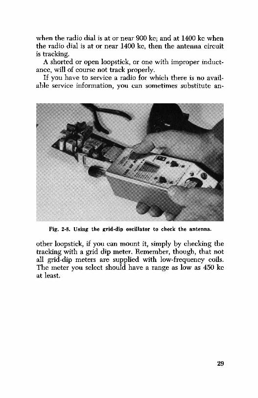
when the radio dial is at or near 900 kc; and at 1400 kc when the radio dial is at or near 1400 kc, then the antenna circuit is tracking.
A shorted or open loopstick, or one with improper inductance, will of course not track properly.
If you have to service a radio for which there is no available service information, you can sometimes substitute an-
Fig. 2-8. Using the grid-dip oscillator to check the antenna.
other loopstick, if you can mount it, simply by checking the tracking with a grid dip meter. Remember, though, that not all grid-dip meters are supplied with low-frequency coils. The meter you select should have a range as low as 450 kc at least.
29

CHAPTER 3
IF Circuits and Their Repair
Unlike conventional IF tube circuits, which have become fairly standardized, there are several kinds of transistor IF circuits. Tube circuits, being high impedance, connect the plate (output) to the grid (input) as shown in Fig. 3-1. Transistor circuits, however, have a low input impedance and only a medium output impedance in the common-emitter circuit, which is the most popular. So transistor IF circuits all have some method of "tapping down" the tuned circuit in order to match the impedances directly. Where most tubes have two tuned circuits in each transformer, the transistor generally has only one. Fig. 3-2 shows the simplest coupling used in transistor work. The collector of the first IF transis-
B+ AVC
Fig. 3-1. High-impedance tube circuits.
tor is connected to one side of the tuned circuit of the transformer. The other side of the tuned circuit is connected to the power source. In other words, the transistor output impedance is across the tuned circuit. The untuned coupling winding connects to the base circuit of the second IF transistor. This winding, which has only a few turns, matches the low ( 200- to 1,200-ohm) impedance of the base circuit 30
1ST IF PNP
AGC
2ND IF
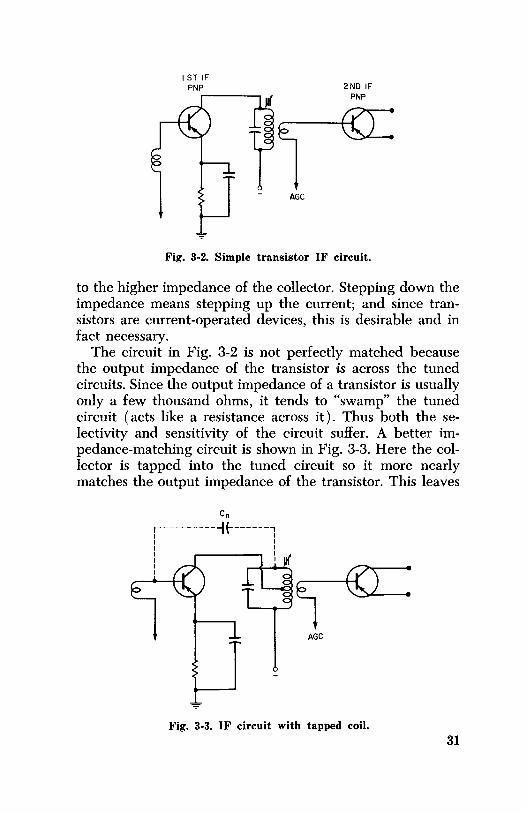
Fig. 3-2. Simple transistor IF circuit.
to the higher impedance of the collector. Stepping down the impedance means stepping up the current; and since transistors are current-operated devices, this is desirable and in fact necessary.
The circuit in Fig. 3-2 is not perfectly matched because the output impedance of the transistor is across the tuned circuits. Since the output impedance of a transistor is usually only a few thousand ohms, it tends to "swamp" the tuned circuit ( acts like a resistance across it). Thus both the selectivity and sensitivity of the circuit suffer. A better impedance-matching circuit is shown in Fig. 3-3. Here the collector is tapped into the tuned circuit so it more nearly matches the output impedance of the transistor. This leaves
Cn
r-----------1 {-------, I I I I I I I ,------, I I I I I
AGC
Fig. 3-3. IF circuit with tapped coil. 31
Cc
I I
JI( I
)I( I I I I I I I I I I
~
AGC
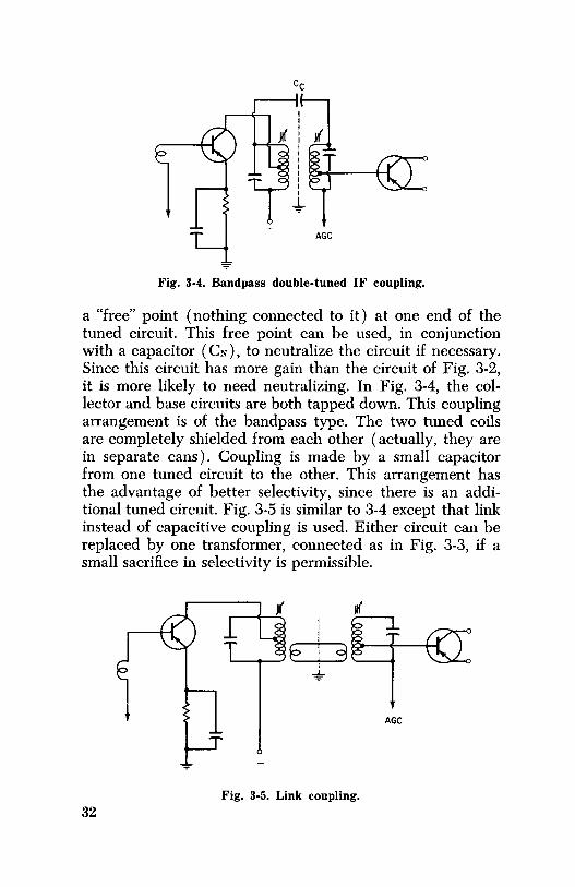
Fig. 3-4. Bandpass double-tuned IF coupling.
a "free" point ( nothing connected to it) at one end of the tuned circuit. This free point can be used, in conjunction with a capacitor ( CN), to neutralize the circuit if necessary. Since this circuit has more gain than the circuit of Fig. 3-2, it is more likely to need neutralizing. In Fig. 3-4, the collector and base circuits are both tapped down. This coupling arrangement is of the bandpass type. The two tuned coils are completely shielded from each other ( actually, they are in separate cans). Coupling is made by a small capacitor from one tuned circuit to the other. This arrangement has the advantage of better selectivity, since there is an additional tuned circuit. Fig. 3-5 is similar to 3-4 except that link instead of capacitive coupling is used. Either circuit can be replaced by one transformer, connected as in Fig. 3-3, if a small sacrifice in selectivity is permissible.
AGC
Fig. 3-5. Link coupling. 32

NEUTRALIZATION
Nearly all early transistor radios needed some form of neutralization in the IF circuits, to prevent self-oscillation, and thus provide better circuit stability. Neutralization is still used by many manufacturers, but there is a gradual trend away from it as transistors and circuit techniques improve.
Neutralization is the feeding back of a specific amount of signal from the output to the input of the same stage. This is done to counteract any tendency for that stage to oscillate, as a result of the capacity between the collector ( output circuit) and base ( input circuit), both inside and outside the
Fig. 3-6. Checking neutralization with a trimmer and
jumper.
CF
i---l~------1
transistor. This residual capacity is represented by CR in Fig. 3-6. Capacity CN is chosen to exactly counteract this residual capacity. Note that the signal at point A is unbypassed and, because of transformer action, is opposite in phase to the signal at the collector. The signal from this point is returned to the base circuit through CN to balance out, or neutralize, the circuit.
Fig. 3-7 shows the form of neutralization used in most early transistor sets. The base of the second IF is connected to the base of the previous stage by a capacitor ( sometimes in series with a resistor). If polarities are correct, the necessary counteracting voltage for neutralization will be supplied. Since the neutralizing voltage is at a lower impedance, this circuit requires a larger-valued feedback capacitor than the circuit of Fig. 3-6.
33

If a neutralized transistor must be replaced, it is best to use the identical substitute. However, this is not always possible. Sometimes you must accept a substitute that is not of the same value, but close enough to work. In this event, reneutralization becomes necessary. It is best to refer to the manufacturer's service information when reneutralizing. Should this information be unavailable, however, the trialand-error method must be used. The only sure way you can tell whether neutralization is needed is to substitute the transistor and listen for squeals or howls in the receiver. Don't try to stop the squealing by detuning the IF transformers-
Fig. 3-7. Base-to-base neutralization.
this will only lower the gain and increase the noise. If neutralization is needed, then it should be performed.
Before neutralizating you will have to zero-bias the transistor to cut it off. A jumper from point B to C in Fig. 3-6 will do the trick. Now, with the transistor having no gain, only its capacity and the associated wiring can pass the signal on to the next stage. Using either a signal generator or a very strong broadcast station, inject a signal into the antenna circuit. (You should be able to hear a small output in the speaker.) Now connect a trimmer ( 3-30 mmf for the circuits in Fig. 3-6; 20-80 mmf for those in Fig. 3-7) into the circuit, using short lengths of wire. Adjust the trimmer until the signal is no longer heard ( or is barely heard). This sets the trimmer to counteract the residual capacity of the circuit. Remove the trimmer and measure its value on an ac-34

curate capacity bridge. Finally, permanently install a ceramic or mica capacitor of the indicated size.
The most comomn cause of IF circuit squeals, other than a transistor, is an open bypass capacitor ( especially an electrolytic). When you have a "squealer," you should first shunt each electrolytic with a 20-mfd capacitor. This method of checking for open capacitors is faster and easier than removing each component one by one and checking it with a meter.
TROUBLESHOOTING
After localizing the trouble to the IF, you should first check the transistor for diode action ( as explained in Chapter 2) without removing it from the circuit. The next step is to turn the radio on and check the base-to-emitter bias. This should be about 0.1 to 0.3 volt and of the correct polarity.
Fig. 3-8. Typical IFamplifier circuit.
@
FROM AGC
@ IK
@
If Cl in Fig. 3-8 opens, squealing or motorboating most likely will occur. The simplest and best way to check Cl is to shunt a good capacitor across it. However, if Cl shorts out, the radio will then be dead ( or at least very weak), and the base-to-emitter bias will be zero. If C2 or C3 opens, the radio will be weaker than normal and have that "not quite right" quality that's hard to put your finger on. Obviously, if C3 shorts there will be insufficient collector voltage and thus no amplification. Unfortunately, however, capacitors do not always conveniently open or short; instead, they develop varying amounts of leakage internally. When either C2 or
35

C3 develops leakage, the bias of the circuit is. upset and the result will be a weak or dead radio.
Since the average collector current of the RF or IF transistor is around one milliamp, you can sometimes spot a leaky capacitor ( or transistor) by a study of the bias voltages. For instance, in the circuit of Fig. 3-8 there should be about a one-volt drop across R4. If the IR drop is much greater, C3 may be leaky. Disconnecting it at one end will confirm or deny your suspicion. Remove the transistor from the circuit ( if it isn't a plug-in type, use the "razor blade" technique explained in Chapter 7), and again check the voltage drops to spot the trouble.
CHECKING IF TRANSFORMERS
A foolproof diagnosis of a defective IF transformer is difficult to make. Obvious faults such as open windings are not hard to find, but deciding whether the signal transfer is adequate or not is another matter. Here are some hints to help you. If the transformer had not been tuned previously, and the slug must be turned more than one complete tum to obtain peak resonance, then the transformer is almost surely bad. If the slug must be moved to one extreme or the other to get maximum signal, then the transformer should be replaced. And if you get no peak at all, then it is most certainly defective.
I I I I I I I I I I I I
+
Fig. 3-9. Broken coils at points X or Y.
In the circuit of Fig. 3-9 the winding may break at either point X or Y, in which case there will be no signal transfer. In some sets you cannot even get to these points in order to check them. They are inside a shield, and the coupling capacitor goes through the side. In this case, only signal tracing can spot the trouble. 36

OTHER IF CIRCUITS
In the GE circuit in Fig. 3-10, a single IF coil is used. Coupling to the base circuit is made through a 510-mmf capacitor, and the base is bypassed with an 8,200-mmf capaci-
510 MMF
Ave BIAS
Fig. 3-10. Capacity coupling.
tor. In a tube circuit this arrangement would hardly work. In a transistor circuit, though, it represents an impedance match. Notice that both capacitors are in series across the IF coil. This network forms a resonant circuit at 455 kc. An 8,200-mmf capacitor has a reactance of about 50 ohms
.----+---'V\/\;-- BIAS
I Fig. 3-11. Combination base and emitter coupling.
at 455 kc, and this effectively matches the low-impedance base circuit. The advantage of this circuit is that, by juggling the value of this base bypass capacitor, you can effectively match the dynamic input impedance of any specific transistor.
37

Fig. 3-11 shows an RCA circuit that has both the base and emitter coupling using a tapped secondary on the IF transformer. Experience has proven that the gain of the stage can often be increased ( without creating any instability) by connecting it as shown in Fig. 3-12.
-----'V'IAr--• BIAS
I Fig. 3-12. Modification of the circuit in Fig. 3-11.
SUMMARY OF IF TROUBLES For a Weak Stage
1. Check peaking of IF transformers. 2. Check bias voltage. 3. Shunt bypass capacitors with known good ones. 4. Check for open resistors. 5. Check transistor. 6. Check for shorted or leaky AGC capacitor.
For a Dead Stage 1. Check for correct voltages on transistor. 2. Check transistor. 3. Check link and capacitively coupled circuits for opens. 4. Check for shorted AGC capacitor.
For a Noisy Stage 1. Check for leaky capacitors. 2. Look for battery acid on board. 3. Check IF transformer for intermittent open. 4. Check transistor.
38

For Squeals and Other Oscillations 1. Check for open bypass capacitors. 2. Check for open neutralizing capacitor. 3. Check for physically abused capacitors. 4. Align the RF and IF stages according to specifications. 5. Check for open capacitor across transformer primary.
( Note: Although not causing trouble directly in the IF circuit, a weak battery is a common cause of squeals and motorboating in a transistor radio.)
39

CHAPTER 4
Detector and AGC Circuits
The diode detector, a mainstay in tube radios, is also popular in transistor types. In tube radios the output of the detector is always negative. However, in transistor radios, it may be either positive or negative. Nor is it just a question of a negative output for NPN transistors or a positive output for PNP transistors. This would be true if AGC were always applied to the base of these transistors. But it is not uncommon for the AGC ( or at least a portion of it) to be applied to the emitter. This, of course, reverses the polarity required to reduce the gain of the stage.
Fig. 4-1 shows four different diode-detector circuits, all identical except for polarity. Figs. 4-lA and C have positive
+AGC
-=-( A) Positive voltage developed.
+AGC
JI(
tl TO
,------VOLUME CONTROL
(C) Positive voltage developed.
JI(
-AGC
TO r---f---+--vOLUME
CONTROL
( B) Negative voltage developed.
-AGC
JI(
f] TO
,----+--VOLUME CONTROL
(D) Negative voltage developed.
Fig. 4-1. Diode AGC circuits. 40
- OUT •I +OUT
CATHODE SEMI-CONDUCTOR
~
UT +OUT
CATHODE TUBE
( A) Semiconductor versus vacuum tube.
( B) Recognizing the positive side.
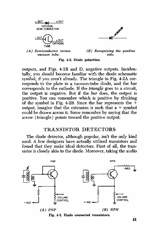
Fig. 4-2. Diode polarities.
outputs, and Figs. 4-lB and D, negative outputs. Incidentally, you should become familiar with the diode schematic symbol, if you aren't already. The triangle in Fig. 4-2A corresponds to the plate in a vacuum-tube diode, and the bar corresponds to the cathode. If the triangle goes to a circuit, the output is negative. But if the bar does, the output is positive. You can remember which is positive by thinking of the symbol in Fig. 4-2B. Since the bar represents the + output, imagine that the extension is such that a + symbol could be drawn across it. Some remember by saying that the arrow (triangle) points toward the positive output.
TRANSISTOR DETECTORS
The diode detector, although popular, isn't the only kind used. A few designers have actually utilized transistors and found that they make ideal detectors. First of all, the transistor is closely akin to the diode. Moreover, taking the audio
PNP NPN
(A) PNP (B) NPN
Fig. 4-3. Diode connected transistors. 41

output from the collector also provides gain in the detector stage. However, transistor detectors are more critical in their bias requirements, especially if they are to work with minimum distortion. In addition, their AGC circuits are usually more complex than when diodes are used. Sometimes a company will use a transistor connected as a diode for the detector. This has no advantage over a diode-except perhaps that the company can now advertise its radio as having seven rather than six transistors! Two such circuits are shown in Fig. 4-3. Note that in Fig. 4-3A the collector and base are tied together, whereas in Fig. 4-3B a resistor is used from the collector to ground.
DET PNP ----
+6V +l.5V
VOLUME CONTROL
Fig. 4-4. Transistor detector circuit.
Fig. 4-4 shows a transistor detector that produces a reasonable amount of gain, in addition to performing its primary job of detecting. Note that there is a "touch" of biasnot enough to make the transistor conduct vigorously, but still enough to keep it ready ( even on weak signals ) in order to prevent signal distortion. This bias is rather critical, since it must be a compromise between maximum gain and minimum distortion of the amplified signal. Fig. 4-5 shows an NPN detector using direct complementary coupling to a PNP driver transistor. The 330-K resistor to the base of the detector provides a slight amount of forward bias in order to reduce distortion. The volume-control center arm is connected to the collector of the detector through a 680-ohm resistor. This connection applies forward bias to the driver transistor. Therefore, more bias is applied as the volume is turned up, since the drop across the detector collector re-42

DET DRIVER NPN PNP
)l(
ff 68O.n.
IK 1OO.n. = 5K
VOL +AGC TO 33OK
IF TRANSISTOR EMITTER
+
Fig. 4-5. NPN-PNP transistor detector.
sistor will be larger. Increasing its bias lets the driver accept larger signals without distortion. Unfortunately, this also increases the current drain from the battery.
Fig. 4-6 shows a transistor detector in which the collector is used not to provide audio gain, but rather to supply amplified ACC. Here's how it works: As more signal is applied to the base of the transistor, the collector current increases. This means the collector voltage decreases ( goes more positive in this case). This positive voltage is then filtered and
Fig. 4-6. Combination transistor detector and AGC
amplifier.
+GOING AGC ----""'
1 K"-
DET-AGC PNP ----'
12K
-9V
VOL
TO BASE OF AUDIO DRIVER
43

applied to the base circuits of the PNP IF transistors to lower their gain. Since the voltage change is greater than it would be with a diode detector, this circuit is aptly called an amplified AGC circuit.
AUTOMATIC GAIN CONTROL
In tube-type radios this same control of gain is called automatic volume control ( A VC), but the common practice in transistor radios is to call it automatic gain control ( AGC).
Automatic control is more difficult to obtain in transistor than in tube radios, because a transistor ( like a triode tube) tends to have a flat bias-versus-gain curve, as shown in Fig. 4-7. Between 0.1 and 0.3 volt, the gain of the transistor is
50
40
30
20
10
{
I J)
r '\
' ' \ \ \ \
0o .05 .I .15 .2 .25 .3 ,35 .4
Fig. 4-7. Bias versus gain characteristics.
virtually unchanged, but drops sharply almost to zero at about .09 volt. Since the cutoff bias varies, even in transistors of the same type, the designer must set the bias somewhere in the middle, or about 0.2 volt, to make sure the transistor will operate at full gain on weak signals. The AGC voltage must not reduce the voltage to below the .09-volt point on moderately strong signals, or the sensitivity of the set will be reduced too much. So you can see the dilemma of the design engineer. If the AGC is too active, the set loses sensitivity. On the other hand, if the AGC is not active enough, the set will have very little control because the gain doesn't change much within the strictly defined limits of 0.1 to 0.3 volt in the example given. ( Different transistors, of course, have different bias-versus-gain curves.)
There are other AGC problems. On very strong stations the AGC may cut the transistors off. Because of diode action, however, the signal itself can make the transistors conduct on strong modulation peaks. This is somewhat like the blocking experienced in tube sets. Distortion occurs because the 44
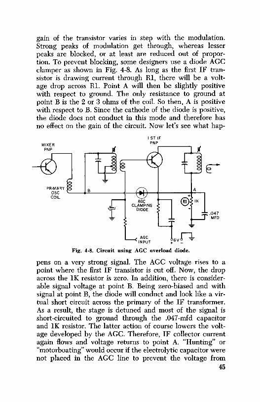
gain of the transistor varies in step with the modulation. Strong peaks of modulation get through, whereas lesser peaks are blocked, or at least are reduced out of proportion. To prevent blocking, some designers use a diode AGC clamper as shown in Fig. 4-8. As long as the first IF transistor is drawing current through Rl, there will be a voltage drop across Rl. Point A will then be slightly positive with respect to ground. The only resistance to ground at point B is the 2 or 3 ohms of the coil. So then, A is positive with respect to B. Since the cathode of the diode is positive, the diode does not conduct in this mode and therefore has no effect on the gain of the circuit. Now let's see what hap-
MIXER PNP
PRIMARY
I ST IF PNP
A B osc '---...:::.----~--+ .... +---+------+--, COIL +
AGC @ IK CLAMPING
! DIODE
... AGC 6Vn
INPUT + -
Fig. 4-8. Circuit using AGC overload diode.
e
.047 MFD
pens on a very strong signal. The AGC voltage rises to a point where the first IF transistor is cut off. Now, the drop across the lK resistor is zero. In addition, there is considerable signal voltage at point B. Being zero-biased and with signal at point B, the diode will conduct and look like a virtual short circuit across the primary of the IF transformer. As a result, the stage is detuned and most of the signal is short-circuited to ground through the .047-mfd capacitor and lK resistor. The latter action of course lowers the voltage developed by the ACC. Therefore, IF collector current again flows and voltage returns to point A. "Hunting" or "motorboating" would occur if the electrolytic capacitor were not placed in the AGC line to prevent the voltage from
45

changing too rapidly. The circuit comes to rest at a median point so that the diode conducts just enough to stop an overload.
Some radios use diode-connected transistors ( collector to base shorted) for AGC clamps as well as for detectors. Fig. 4-9 shows a circuit with a so-called AGC amplifier. Actually, it works almost the same as if it were connected as a diode. Normally the base-to-emitter bias is positive, and so the transistor is cut off. This bias is dependent on the voltage drop across the 2.2K collector resistor in the first IF transistor. The collector voltage for the AGC transistor is determined by the voltage drop across the 560-ohm mixer collector resistor. Both the mixer and the first IF have AGC applied to them. As long as the AGC voltage is insufficient to cut off the collector currents, the bias on it prevents the AGC transistor from conducting. However, if the mixer and IF collector currents are cut off, the AGC transistor will then be zero-biased and cannot conduct, although it has signal voltage from the mixer on the collector. This signal biases the collector so that it becomes a diode to the base. As a result, some of the signal voltage is shorted out, as explained for the clamper diode.
To keep diode action from being too abrupt ( there is only a slight change of voltage at the critical point between conduction and nonconduction), some designers place a resistor in series with the diode.
TROUBLESHOOTING
Semiconductor diodes are not too difficult to check. The ohmmeter method is virtually foolproof. Diodes should measure from 25 to 150 ohms in the forward direction and 200K or more in the reverse direction. In the circuit they should measure about the same in the forward direction, but in most circuits will only measure about 5K in the reverse direction, due to added parallel resistances. If you do suspect the diode, you should make a final check with one end disconnected.
Transistor detectors are checked just like any other transistor. However, if you replace a transistor detector with one of a different type number, you may have to use bias resis-46

tors of slightly different values in order to minimize distortion. A resistance substitution box is ideal for this. Before settling on the resistor value, it is best to check the substitution by tuning to both a strong and a weak station.
Clamping diodes can probably best be checked by simply disconnecting one end. With normal to moderately strong signals, there should be no difference in volume with the diode connected or disconnected. The same is true for tran-
MIXER
IK
AGC INPUT
~ 25 "$'"MFD
560.n.
~.100 ..L MFD =
430.n..
2.2K -av
100.n.
9Vn. - +
Fig. 4-9. Circuit using transistor as AGC overload clamper.
sistor clampers. In the circuit of Fig. 4-9, disconnecting the collector should not change the volume. Clampers are notorious offenders when the problem is a weak radio, so don't forget to make the above check if you are at all suspicious. Almost any good diode or transistor can be used as a replacement in this circuit.
To check the clamping action, tune in a fairly strong station and short out the collector resistor in the first IF ( the lK unit in Fig. 4-8). The volume should drop drastically. If it doesn't, the clamper is not working properly.
Motorboating in transistor radios is nearly always caused by improper filtering of the AGC line. So your first step is
47

to bypass the AGC line with a known good electrolytic. ( Be careful to observe the correct polarity.)
A shorted or leaky AGC capacitor is a prevalent cause of weak or even dead radios. It is not too unusual for an electrolytic bypass to be intermittent. This should always be checked when the complaint is that the radio suddenly goes dead while playing. Although there are other causes ( such as a broken printed circuit or leaky transistor), electrolytics seem to be the most common offenders.
48

CHAPTER 5
Servicing the Audio Stages
The most common, and also most efficient, transistor audio driver employed today uses transformer coupling. In the simple circuit in Fig. 5-1, the audio is coupled from the volume control into the base of the driver transistor through a 10-mfd electrolytic capacitor. ( Electrolytic high-capacity couplings are necessary since, unlike tube circuits, the input of the driver has a low impedance-usually less than a thou-
47K
I.QI MFD
~ +9V -
Fig. 5-1. Transformer-coupler audio driver.
sand ohms.) The base circuit of the driver is forward-biased by resistors Rl and R2. Protective biasing for the transistor is supplied by emitter resistor R3, which is bypassed ( to prevent degeneration and loss of gain) by 50-mfd capacitor C2.
Fig. 5-2 shows a slightly more complex version of the circuit in Fig. 5-1. The main difference is the 22-ohm unbypassed resistor connected in the emitter lead, in series with the regular bias network. A connection from the voice coil to this resistor feeds back a degenerative signal ( inverse feed-
49

220
b MMF
c:lf:iL ~o~.----+--t MFD
4.7K FROM ONE SIDE OF
VOICE COIL
Fig. 5-2. Driver with degenerative feedback.
back) to improve the frequency response of the driver stage. C4, the 220-mmf bypass capacitor between the collector and base, reduces the gain of the stage at high frequencies by degenerative feedback.
Note that both circuits use PNP transistors. In Fig. 5-1 the negative side of the power supply is returned to ground, whereas in Fig. 5-2 the positive side is grounded. PNP transistors are more popular than NPN's; nevertheless, the two are identical except for battery polarity.
Fig. 5-3 shows a resistance-coupled audio-driver stage. Although sometimes used to directly drive an output stage, it more often drives another stage similar to those in Figs. 5-1 and 5-2.
50
TO 'f'-- NEX:r 10 STAGE
MFD
3K
9Vn-+
Fig. 5-3. Resistance-coupled driver stage.

Resistance-coupled transistor stages are low gain for at least three reasons: ( 1 ) Any resistance in the collector circuit lowers the collector voltage, and since there isn't much to spare in battery radios, the size of the collector resistor must be rather limited in value. ( 2) As mentioned, the battery voltage is low ( compared with that of a resistancecoupled tube amplifier) and so the voltage swing ( which can't exceed the battery voltage) is limited. ( 3) Most important, the impedance of the following stage is low; and since it is in parallel with the collector resistance, a mismatch exists and further lowers the efficiency of the circuit.
PLAYBACK IOOK
HEAD
r--~---7 : I I
I I IMFD I I I I I I !_ ____ J
47K
50 MFD
3.3K
L__._ TO TUBE ,------AMPLIFIER
.01 MFD
150K
+125V
Fig. 5-4. High-gain tape-rec:order amplifier.
It should be pointed out here, however, that a resistancecoupled transistor amplifier is capable of high gains when used in a tube circuit, such as in a tape recorder preamp. In this circuit ( Fig. 5-4), the supply voltage and load resistors are both high in value and the output is fed into a high impedance. Transistor circuits like this may have voltage gains of 150 or more, depending on the transistor and circuit used.
REFLEX AMPLIFIERS
The one audio driver that is least conventional, yet quite prevalent in small transistor radios, is the reflex circuit. This circuit uses one transistor to amplify two separate signals at once, usually the IF and AF.
51
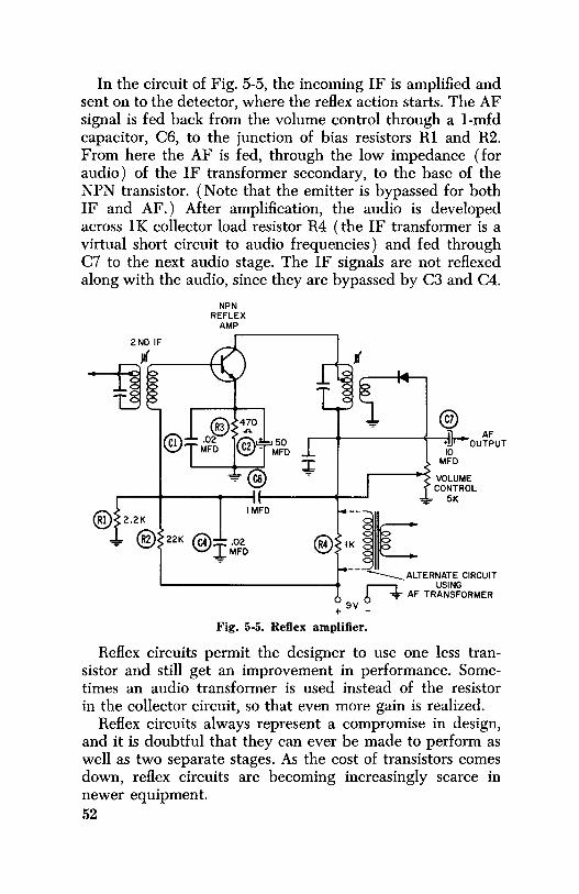
In the circuit of Fig. 5-5, the incoming IF is amplified and sent on to the detector, where the reflex action starts. The AF signal is fed back from the volume control through a 1-mfd capacitor, C6, to the junction of bias resistors Rl and R2. From here the AF is fed, through the low impedance ( for audio) of the IF transformer secondary, to the base of the NPN transistor. ( Note that the emitter is bypassed for both IF and AF.) After amplification, the audio is developed across lK collector load resistor R4 ( the IF transformer is a virtual short circuit to audio frequencies) and fed through C7 to the next audio stage. The IF signals are not reflexed along with the audio, since they are bypassed by C3 and C4.
2ND IF
~ @
NPN REFLEX
AMP
@
IMFD ® 2.2K
~ @2 22K @ 02
I . MFD
50 MFD
@ n______ AF
.-----------,-•!.fo'"""ouTPUT
@,]~ 10
MFD
VOLUME CONTROL
= 5K
------ ALTERNATE CIRCUIT r--::1._ USING 6 ~ AF TRANSFORMER
+ 9V _
Fig. 5-5. Reflex amplifier.
Reflex circuits permit the designer to use one less transistor and still get an improvement in performance. Sometimes an audio transformer is used instead of the resistor in the collector circuit, so that even more gain is realized.
Reflex circuits always represent a compromise in design, and it is doubtful that they can ever be made to perform as well as two separate stages. As the cost of transistors comes down, reflex circuits are becoming increasingly scarce in newer equipment. 52

OUTPUT AMPLIFIERS
Unlike most tube radios, which use a single class-A amplifier as an audio output, most small transistor radios use two transistors in class B. The reason is that, for the same power output, class-B stages are considerably more efficientwhich is merely another way of saying that less battery power is required. Class-B stages are biased almost to collector-current cutoff. ( In the strictest sense, they should perhaps be called class AB). They conduct only slightly, except when actually amplifying a signal, and then only in proportion to the instantaneous value of modulation.
A class-A stage, on the other hand, must be biased for much greater conduction. The current of a class-A stage is the same, whether a signal is being amplified or not.
All other factors being equal then, a class-B stage with two transistors draws less standby current and is therefore more economical ( from the standpoint of batteries) than a class-A stage with only one transistor.
Class-A Amplifier Many radios, including nearly all car radios, use a class-A
output stage. ( All single-transistor driver stages are class A, also.) Fig. 5-6 shows a class-A output circuit with the same biasing layout found in the other transistor circuits discussed. The only difference is that in the class-A output stage, the bias resistors are chosen so that there is more forward bias.
DRIVER
l.01
560.n.
-.7V
50 MFD
8.2K
56.n.
Fig. 5-6. A class-A output stage.
17MA
8 - 9V +
53

This has two primary effects: ( 1) more collector current, so that more power can be developed for driving the speaker, and ( 2) greater base-to-emitter bias, to permit a larger input signal voltage without cutting off the transistor and thereby causing distortion.
Where the current of a mixer, IF, or driver stage may not exceed 1 to 2 milliamps, a typical class-A output stage in a small radio may have a collector current of 15 to 25 ma. Moreover, car radios may have as much as 1 amp or more.
Unlike a tube circuit, which can use cathode biasing exclusively, emitter biasing alone is not possible in transistor circuits because, unless a fixed forward bias is applied to the base, there can be no emitter current and therefore no emitter bias can be developed. In addition, the emitter resistor does reduce the current of the transistor and thus acts as a thermal runaway protector. At the same time, however, it actually reduces the base-to-emitter voltage. This means that even if emitter bias alone could be replied upon, the bias voltage will inherently limit the input signal that could
BIAS VOLTAGE INCREASES
WITH INCREASE IN PLATE CURRENT
+
Fig. 5-7. Tube and transistor biasing.
be accepted without distortion. For example, if the output stages were overdriven, the collector current would increase; this would decrease the voltage between the base and emitter, and so produce even more distortion. In a tube with cathode bias, the grid-to-cathode voltage would increase and thus tend to counteract the distortion caused by overloading. A comparison between tubes and transistor is shown in Fig. 5-7.
Propertly biased, a class-A output stage has a fidelity as good as or better than that of any other class of amplifier. However, its power output must be limited where transistor 54

size and battery economy are prime design factors, such as in portable radios.
Class-B Amplifier
Class-B output stages are far more popular than class A in small radios, even in midgets. Class-B stages use two transistors, each working on alternate halves of the audio cycle. Class-B stages are biased almost to cutoff when no input signal is applied. Notice in Fig. 5-8 that the base bias consists of a 4,700- and a 100-ohm resistor. The center tap of the input transformer is connected to their junction. This means t~at only about 2% of the voltage, or less than 0.2 volt, is applied to the base of the two class-B output transistors as bias. This is not much more than some RF and IF transistors
-
i -9V
Fig. 5-8. Class-B push-pull output.
have. Both class-B transistors will draw 8 to 10 ma without a signal. When a signal is applied, one half-cycle will drive the base of the upper transistor negative ( and the lower one positive), and the upper transistor will then conduct in proportion to the strength of the signal. On the next half-cycle, the base of the lower transistor will be driven negative and will conduct while the upper one is cut off.
The only reason for DC bias is to eliminate crossover distortion. That is, at low bias values the collector current change is not linear with a change in base bias. This nonlinearity causes distortion because a small input signal will be amplified out of proportion to a strong signal. For this
55
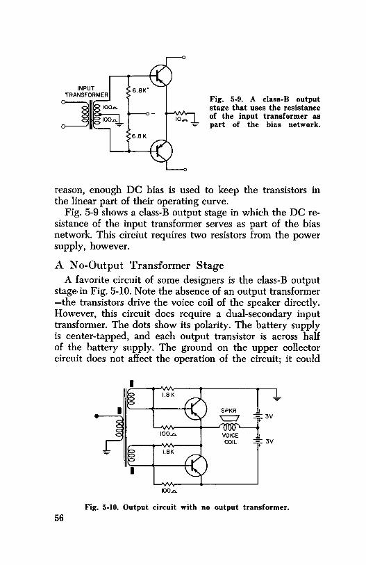
Fig. 5-9. A class-B output stage that uses the resistance of the input transformer as
= part of the bias network.
reason, enough DC bias is used to keep the transistors in the linear part of their operating curve.
Fig. 5-9 shows a class-B output stage in which the DC resistance of the input transformer serves as part of the bias network. This circiut requires two resistors from the power supply, however.
A No-Output Transformer Stage A favorite circuit of some designers is the class-B output
stage-in Fig. 5-10. Note the absence of an output transformer -the transistors drive the voice coil of the speaker directly. However, this circuit does require a dual-secondary input transformer. The dots show its polarity. The battery supply is center-tapped, and each output transistor is across half of the battery supply. The ground on the upper collector circuit does not affect the operation of the circuit; it could
100..n.
Fig. 5-10. Output circuit with no output transformer.
56

be at the emitter of the lower transistor or anywhere else. This circuit requires a negative ground, however, because the whole battery is used to power the rest of the radio.
Voice-coil impedances for this circuit are usually 25 to 100 ohms. An 8-ohm voice coil will limit the power output, but may work surprisingly well.
A Tapped Voice-Coil Circuit Fig. 5-11 shows an RCA circuit that uses a tapped speaker
voice coil rather than an output transformer. The biasing circuit also provides inverse feedback, since the 5,600-ohm resistors are connected to the collectors rather than to the negative side of the power supply (ground). Needless to say, it is impossible to replace this speaker with a two-wire type.
5.6K
2N408 PNP
.33 MFD
+ -
2N408 PNP
130..n. CT
Fig. 5-11. Class-B stage using a center-tapped voice coil.
A peculiarity of this circuit is that when one half of the voice coil opens, the symptom will be audio oscillations-but if the other half opens there will only be severe distortion. This has to do more with the circuit layout in the RCA model PTl and others than with lack of symmetry in the circuit.
Thermal Protection Many manufacturers provide some method of thermal pro
tection for both class-A and -B output stages. This is desirable since transistors tend to draw more and more collector current as their temperature increases. Emitter resistors tend to provide thermal protection automatically because, as the
57

current increases the bias decreases, reducing the collector current. ( Remember, in transistors, that reduced bias means less collector current-in tubes, however, reduced bias means more plate current.) Emitter resistors have a degenerative effect on the circuit, especially if they are unbypassed, and thus lower the gain of the circuit. Many companies rely on temperature compensation in the base bias circuit. Three methods for doing this are shown in Fig. 5-12. In Fig. 5-12A
(A) Using a Thermistor.
( C) Using a diode.
INPUT TRANS
(B) Using a transistor.
Fig. 5-12. Methods of protecting class-B stages from thermal
runaway.
a special resistor that decreases in resistance with an increase in temperature ( negative temperature coefficient) is connected across the 220-ohm bias resistor. This Thermistor, as it is usually called, reduces the DC bias on the transistors as the ambient (surrounding) temperature increases. So, as the temperature increases the current of the transistors, the 58
Thermistor ( by reducing the DC bias) thus holds the current at a safe level.
In Fig. 5-12B the action is almost identical to that of Fig. 5-12A except that the Thermistor has been replaced by a transistor. It may be identical to the output transistors, or at least will have similar temperature-versus-current response. Its collector is tied to its base so that, for all practical purposes, the transistor is a forward-biased diode. As the temperature increases, the diode conducts more-which is the same as saying that its resistance is lowered-and so the bias on the output transistors is also lowered.
The circuit in Fig. 5-12C actually uses a diode to counteract any tendency of thermal runaway. The series bias resistor in all these circuits is chosen to provide the least current that can be tolerated without causing distortion in the output stages.
TROUBLESHOOTING
Distortion in transistor audio amplifiers has essentially the same causes as in tube amplifiers. They are incorrect bias and incorrect supply voltage. In addition, defective transformers cause more trouble in transistor radios than they do in tube radios, probably because their smallness makes them rather fragile.
Incorrect bias can be caused by several conditions. The most common are an open bias resistor, a leaky transistor, or a leaky coupling capacitor.
Distortion is sometimes "designed in" at low volume by an attempt to reduce the standby current of class-B stages too much. One manufacturer recommends a modification in one of its models, to eliminate distortion at low volume. He suggests shunting the 4,500-ohm resistor in Fig. 5-13 with a 15K.
Radios with class-B stages should draw at least 8 to 10 ma with no signal input ( volume turned down). If they draw less than this, there is a good chance they do not have enough forward bias on the output stage. The radio will not be damaged if you increase the current to 15 ma or so in order to reduce or eliminate distortion. However, there will be more current drain from the battery.
59

In class-B circuits, if one transistor opens or has excessive leakage, distortion will result. Transformers often open and thus keep the signal from being fed to one transistor. A more common occurrence is for the transformer to develop shorted turns. This usually causes more distortion in one half of the secondary than the other. A signal tracer is ideal for finding the trouble.
r---1sK ~ (:!:)? 4.5K
I
Fig. 5-13. Lowering the value of a bias resistor to reduce
crossover distortion.
In the "no-output-transformer" circuit, each transistor is biased individually. Hence the bias voltage between the emitter and base of each must be tested. The bias should be the same on each transistor.
Bad speakers are another source of distortion. Most radios have earphone jacks in the voice-coil circuit. A handy unit for testing distorted or open speakers is a speaker wired to an earphone plug. Plugging in the test speaker disables the old speaker and lets you listen to the radio output with a known good speaker.
Caution: When using a signal tracer to track distortion in a transistor radio, keep the volume setting of the signal tracer as low as possible. Distortion is much easier to distinguish at low volume. Often a signal that is distorted at low volume will sound pretty good at high volume.
,veak Audio By far the most common cause of weak audio is an open
electrolytic coupling or bypass capacitor. There is probably 60
no faster or more effective way of checking them than by simply shunting each one with a known good capacitor. However, a signal tracer will also help you find the trouble, since with open coupling capacitors there will be more audio on one side of them than on the other.
Since all electrolytics are subject to failure in transistor radios, you should always shunt-test them before making any other tests. Such a method might at first seem rather crude, but it is in reality highly effective. Transistor radios are harder to circuit-trace since they have few guide points. So it's usually harder, unless you are familiar with the radio, to spot a particular capacitor that you might want to test than simply to shunt each of them individually. A whole radio usually has no more than five or six capacitors.
REPLACING TRANSISTORS
Just about any transistor will work as an audio driver, but the so-called "universal" transistor replacement often has low gain. For driver stages, an IF transistor may work more satisfactorily.
Output transistors do not have to be matched by any rigid set of specifications. If, after replacing the output transistor, the radio sounds all right and current drain is not excessive, the replacement transistor is undoubtedly satisfactory. Pay particular attention to how the radio sounds at low volume. If you hear any distortion, then increase the bias slightly until the distortion disappears.
Many transistors recommended for other circuits can be used as audio outputs. The current drain is usually not a factor, although output transistors do operate with more collector current. More important is the voltage rating of the transistor. A transistor rated for a 6-volt output circuit should not be used in a 9-volt circuit, although there is no harm in going the other way. That is, using a 9-volt transistor in a 6-volt circuit.
61

CHAPTER 6
Over-all Service Techniques
Whatever or however you service, you probably use some sort of "divide-and-conquer" technique. The secret of fast and efficient servicing is to use a refinement of this basic approach, which is simply a process of going from the known to the unknown-i.e., from proving what is good to what is bad. As an example, the TV you are servicing may have audio and a full raster, but no picture. You immediately decide that the low- and high-voltage supply circuits are all right. You know the IF and tuner circuits are probably all right, too, since the sound is normal ( although the trouble could be in the AGC). This leaves the first suspect-the video-amplifier circuit. All this deduction took you less than 30 seconds if you are a good TV technician, and whether you realize it or not, this is dividing to conquer, or going from the known to unknown.
The procedure for transistor radio servicing is the same. If you have a dead radio and can somehow prove, for instance, that the audio stages are working properly, this divides the circuit, indicating that the trouble is in either the mixer, detector, or IF stage. Next if you can somehow quickly prove that the IF and detector stages are OK, you have isolated the trouble to the mixer/oscillator stage ( or RF stage if the radio has one). Making these divisions quickly is often more an art than a science. Given enough time, almost anybody could repair a transistor radio. The art is in cutting the time down to where the repair is profitable. Unless you can refine your service techniques to the point where you can find the answers quickly, you will never realize the profits possible in radio service work and especially in transistor servicing. 62

The techniques you use may range from the crude to the sophisticated, from the simple to the complex. Don't worry if a technique seems crude, though, as long as it helps you find the trouble faster. As an example, bypassing every electrolytic in the set when you have a weak, squealing, or motorboating radio might seem crude, but most assuredly there is no better or faster method, especially if you are unfamiliar with the layout of the radio.
Every problem will probably respond best to one particular technique, but since you don't know in advance what the trouble is, the selection of the technique is also part of the "art." If some problem steadfastly refuses to respond to your best method of troubleshooting, you should have another method ready-not because another way might be better, but because a change in technique often rearranges your thinking. Maybe you can't see the forest for the trees and need to take another path into the woods.
SO LET'S REP AIR A RADIO
Don't try to service transistor radios unless you have a power supply that meets the specifications listed in the chapter on equipment.
TO RADIO
Fig. 6-1. Snap-on plug polarity.
+ The first step is to connect the radio to the power supply,
carefully observing the polarity and voltage. On snap-fastener battery plugs ( Fig. 6-1), the male plug on the radio is negative and the female, positive. On other kinds of plugs the red wire is usually positive and the black, negative. You're not likely to damage a radio if you momentarily connect it to reversed polarity; however, you should watch the
63

milliammeter on the power supply when you turn the radio on. If the current is over 25 or 30 ma, then immediately check the polarity. Also be sure the voltage to which the radio is connected isn't too high. If the voltage and polarity are correct but the current is still high, you must find out why.
The most common causes of high current are: ( 1) shorted or leaky electrolytics, ( 2) shorted or excessively leaky transistors, ( 3) open output bias Thermistor, diode, or diode-connected transistor, or ( 4) shorted wiring. The "razor blade" technique of isolating a defective power-supply electrolytic or a defective transistor is explained in the next chapter. A simple check for a defective bias component is to short across
Fig. 6-2. Shorting the bias resistor.
it as shown in Fig. 6-2. If the component is defective, the high current should drop almost to zero.
What If Current Is Low?
Low current is a rather uncommon trouble. It can be caused by an open bias resistor on the output stage. Normal current drain for a radio with class-B output stages is 6 to 12 milliamperes. For class-A output ( single transistor), the current for the whole radio will be about 12 to 25 ma.
Of course, if there is no current drain, then there may be open wiring or an open switch.
,vhere To From Here?
If the current tests are inconclusive ( neither too high nor too low), then you must start all over. Let's say the radio is dead. Hold the radio speaker to your ear and move the 64
volume control back and forth. It's a rare radio that doesn't have a little noise, in the control, which you can hear with the speaker close to your ear. If you hear noise you can assume, for the time being, that the audio stages are OK or else they wouldn't have passed the noise. Therefore, the trouble is in the mixer, IF, or detector stage. However, if there was no noise, then a further check on the audio stages must be made.
A speaker wired to an earphone plug makes an ideal test unit for audio-stage work. Since most earphone jacks are in the voice-coil circuit, plugging in a speaker helps you check not only the speaker of the radio, but also the earphone switch as well. This switch is a common offender in transistor-radio troubles. If, after plugging in the speaker you still hear nothing, hold something metallic like a screwdriver blade in your hand and scrape across some point in the signal path of the audio stages ( say, at the collector of the driver). You should hear a faint scratching noise in the speaker. Move back to the base and see if you get another scratching noise. You won't hear a hum in these circuits, as you will from a tube radio, since the circuits are low in impedance. However, you should be able to create an audible disturbance.
After isolating the trouble to a particular stage, you are then ready to make voltage readings on that stage, paying particular attention to the polarity of bias.
Remember that voltage readings in a defective transistor stage are not like those in tube stages. There is always some resistance between the elements of a transistor. If the open circuit is outside the transistor itself, the open transistor element will assume the voltage of the other elements as far as a meter is concerned. For example, if the primary of the audio transformer in Fig. 6-3 opened, there would be approximately 9 volts on the collector ( it normally is nearly zero). However, if the primary in Fig. 6-4 opened, the voltage would be nearly zero on the collector. What this really boils down to is that if the voltage on all three elements of a transistor are about the same, the trouble is an open circuit element or a shorted transistor. ( A shorted transistor would likely increase the current drain of the radio considerably.)
An open emitter circuit will have voltages similar to those in Fig. 6-5. Note that here the collector voltage remains the
65

AUDIO ,__ill __ s._2_v-t--l
INPUT~
+ -9V
[
Fig. 6-3. Open external collector circuit (negative ground).
same but the emitter assumes the voltage of the base, since the base is forward biased ( or will be when the meter is connected). In this case there is very little resistance between the base and emitter, whereas the resistance between the collector and emitter is quite high ( unless the transistor is leaky).
In Fig. 6-6 the voltages indicate a leaky transistor. Notice that the emitter voltage is lower than the base voltage. In other words, the transistor is reverse biased and therefore no emitter current at all will flow. About the only way it can is for leakage to occur between the collector and emitter. Such a transistor must be replaced.
66
-.5V
r+ - + 9V
Fig. 6-4. Open external collector circuit (positive ground).

-.av
[+ - + 9V
Fig. 6-5. Open external emitter circuit.
The above discussion on voltages applies to any transistor stage ( RF, mixer, IF, or audio). Let's suppose the audio stages are OK. What then? The next step is to hold the radio near a fluorescent lamp. ( Every transistor radio technician should consider a fluorescent lamp for his bench light and as a piece of test equipment-it is an ideal noise generator, useful both for circuit tracing and for alignment.) Do you hear noise? Then there's a good chance that you have trouble in the mixer-oscillator stage.
If you don't hear noise, again touch the blade of your screwdriver to the collector terminal of the mixer. This is the same as putting an antenna on the IF stage. If you can hear the fluorescent noise now, then the IF is passing the signal. If you can't hear the noise, then move your screw-
~ - + 9V
Fig. 6-6. Leaky transistor. 67

driver to the first IF collector and listen again. You may have to grab the fluorescent lamp with your other hand to increase the noise input to the radio. You now should also be able to inject a signal into the collector of the second IF and still hear the noise faintly in the speaker. Yon can prove how well this method works by using it for a few repair jobs. It's fast, easy, and efficient; and with these attributes no one can call it crude. Actually, after you have had a little experience, it can turn out to be a most refined technique.
INTERMITTENTS
Anything intermittent is a problem to troubleshoot, but with transistor radios you have some advantages. They're small enough that you can flex the circuit board and the parts on it easily. Also, since there are no voltages to speak of, you can use your fingers as probes. If, by judicial flexing of the board or parts you can get the radio to act up, the trouble usually is more than half whipped. For printed-circuit troubles a thorough inspection of the board is recommended. If your eyes are not as strong as they used to be, a magnifying glass is helpful. You can even purchase a fluorescent bench lamp with a built-in magnifier. Don't purchase an economy model, though, unless you check out the magnifier. It may give you a headache every time you inspect a set.
For intermittents that stubbornly refuse detection, a good case history of the radio is important. Be sure to get all the information you can from the owner. Does it act up on weak stations? At the high or low end of the dial? After playing awhile? When hot or cold? The more information, the better. The solution to the problem often lurks in seemingly unrelated events.
If the trouble occurs only on weak stations, then it may mean a case of AGC trouble, or simply that the station fades. If the trouble occurs at either the high or low end of the dial, then it is likely in the mixer-oscillator stage-either inadequate bypassing or a defective transistor. Remember that this applies to intermittents only. For a weak radio at one end of the dial, consult the chapter on alignment.
If the intermittent occurs after the radio has played awhile, the two most common troubles are leaky electrolytics and 68

leaky transistors. Either trouble will be noticeable if the set is hot or cold, although the intermittent is more likely to occur when the set is hot. A soldering iron brought close to a suspected transistor or other part may speed up its breakdown time. Don't get the part too hot, though; if it isn't already defective, the heat may damage it.
If the leaky electrolytic is in the power supply, the trouble will show up on your power-supply current meter. However, the meter won't show the effects of a leaky bias or AGC bypass capacitor. These are the components that seem to become intermittent most often, possibly because they have less voltage across them and thus do not break down completely.
Another cause of intermittents is a leaky RF or AF bypass capacitor. These low-voltage capacitors develop leakage quite often, even though there is not much voltage across them. The leakage generally increases with heat, and as a result, the radio may cut off. Bias voltages will usually tell
* VOLTAGE WITH LEAKY CAPACITOR
Fig. 6-7. Leaky capacitor.
TO IF
the story, but not so dramatically as might be suspected. The voltage readings in Fig. 6-7 are given for both a good and a leaky capacitor. Note that the bias between base and emitter has only changed by 0.1 volt. This reading is inconclusive since it is impossible to know just what the bias should be for a particular transistor. In this case, the clue is in the small voltage on the emitter. With a 1.5K resistor, the
69

normal drop acros~ it for this circuit is 0.5 volt-which means that the emitter current is about 0.33 ma. With only 0.1 volt across the resistor the current has dropped to about .066 ma, which is virtually the cutoff point. Had this been an IF stage, the emitter current would probably have run from 0.7 to 1.5 ma. So if you check a mixer stage and find that the emitter current is less than 0.3 ma, you should be suspicious. For IF stages, however, be suspicious if the current drops below about 0.7 ma. Checking the radio schematic will give you some idea of what values to expect.
The IF transformer is another component which frequently becomes intermittent. Usually it does so because the slug has been adjusted so often that it becomes loose. Often you can make an intermittent transformer act up by simply pushing gently on the slug while turning it back and forth, or by wiggling the slug sideways. There is little you can do to a defective IF transformer, though. The best plan is to simply install a new one. However, if it's an emergency and the intermittent is caused by a loose slug or a short, you may be able to temporarily repair the transformer by running paraffin into it after you position the slug ( or short) to get the transformer working again. If this fails, the only recourse is replacement. For information on substituting IF transformers, see the chapter on substitutions.
70

CHAPTER 7
Rapid Diagnosis and Repair
Often you can get some idea of the condition of a component without disconnecting it from the circuit. Certainly this doesn't hold true for every part and every condition, but it does often enough to be a highly useful diagnostic tool.
IN-CIRCUIT CHECKING
Most in-circuit checking should first try to prove that the component is good rather than bad. That is, if you can prove beyond reasonable doubt that a certain component is good ( without removing it from the circuit), then an out-of-circuit test won't be necessary. However, even if an in-circuit test shows a component to be bad, it may not be, and you must make an out-of-circuit test to be absolutely sure. Making such a test without damaging the component or the printed board is often a trick in itself. That is why the "razor blade" technique covered later in this chapter is recommended when part removal is a problem.
First, though, let's go over the in-circuit tests you can make to determine whether final out-of-circuit tests will be needed. Remember, however, that no in-circuit test, where the component tested is shunted by other components, can be 100% accurate at all times.
Transistors
As mentioned previously, the diode-action method of checking transistors in the circuit is fairly accurate. Fig. 7-1 shows a transistor as it looks to an ohmmeter. Between the base and emitter, and between the base and collector, are
71

diodes. Since these diodes often have less reverse resistance than, say, a germanium diode, each diode is shown shunted by a resistance. An ohmmeter reading between the collector and emitter also looks like a diode, but in series with a fairly large resistance ( R4).
To check a diode out of the circuit, connect the ohmmeter leads across it in first one direction and then the other. If a high resistance is shown in one direction and a low resist-
c
PNP PNP
Fig. 7-1. How a transistor looks to an ohmmeter.
ance in the other, the diode is most likely good. Transistors can be checked the same way, for diode action. If, between any two elements, the same reading is obtained in either direction, then the transistor is probably defective. When checking a transistor it is easier to start with the base as the common element, since diodes of the same polarity go to the collector and emitter. You can then reverse the leads and measure the reverse resistance of the two diodes. After doing this, measure the forward and back resistances between the collector and emitter.
In the circuit the transistor must still act as a diode and it will check that way, too. The forward resistances of the diodes between B and C and B and E in Fig. 7-2 will be about the same as they are out of the circuit. However, the reverse resistances are affected by the shunt current paths of other components, and so will now be much smaller. Fortunately, this isn't often a problem. If diode action can still be obtained-that is, the resistance reading is not the same in both directions-you can assume the transistor is all right, at least until you have made further tests on the circuit. 72

BLOCKING OSCILLATOR
TRANSFORMER
.005
BIAS CONTROL
C OSCILLATION
B
5K }
IN-CIRCUIT$ IMPEDANCE L ____ _
E
INDICATOR
I
~ IN-CIRCUIT tlMPEDANCE
\~LNSISTOR UNDER IN
CIRCUIT TEST
Fig. 7-2 Blocking-oscillator method of making in-circuit transistor tests.
Transistor Testers Several companies sell in-circuit transistor testers ranging
from the fairly simple to the more elaborate bridge types. The simple testers work by simply shunting out the circuit impedances ( with the lower impedance of a blocking-oscillator transformer) and supplying bias in the correct polarity to make the transistor operate. A circuit of this kind is shown in Fig. 7-2. A good transistor will oscillate in this circuit even though shunted by circuit impedances in the set ( provided these impedances exceed about 150 ohms at 1,000 cycles). This circuit gives no indication of the gain of the transistor, but only that it will oscillate at an audio frequency and thus is not completely defective. Transistors do not usually change gain or frequency characteristics except drastically, so that any in-circuit test showing the transistor good is pretty sufficient evidence to prove the transistor O.K.
A more elaborate in-circuit tester actually nulls out the input impedances so that they do not affect the transistor test. The output circuit in Fig. 7-3 is swamped by a 1-ohm resistor. DC bias is supplied to produce conduction or cutoff, as the test demands. AC beta (gain) at 1,000 cycles can be read with an accuracy of about 5% in the circuit.
Both of these in-circuit testers are inaccurate whenever the base-to-emitter impedance is below about 150 ohms.
73

IOOO'v osc
BIAS SET
~ ADJUSTABLE RESISTORS
BALANCE OUT RADIO CIRCUIT
IMPEDANCE
Fig. 7-3. In-circuit tester bridging out external circuit impedances.
i 50 7
MFD
(A) Less than 150 ohms.
(C) Low impedance of driver stage.
74
"' NON-ELECTROLYTIC LESS THAN .5 MFD
(B) More than 150 ohms.
Fig. 7-4. Input impedances.
100

However, this doesn't usually happen in radio circuits. Fig. 7-4A shows a circuit with an input impedance of less than 150 ohms at 1,000 cps. This low impedance is the result of the emitter being grounded and the electrolytic being in the base circuit. The circuit you'll find in most radios ( Fig. 7-4B) has an impedance above 150 ohms. Fig. 7-4C shows how an AF driver stage might have low impedance if the volume control is not left at about the midway point.
One of the problems with in-circuit transistor testers is the difficulty in connecting onto the transistor terminals. As shown in Fig. 7-5, building up the terminals with a ball of solder, or temporarily soldering in short pieces of wire, will help eliminate this difficulty.
SHORT WIRES
RADIO CHASSIS BOARD
Fig. 7-5. "Balling up" solder joints, or attaching pieces of wire to circuit board.
A recently developed combination power-supply and "single-probe" transistor tester applies a forward bias to the base of the transistor under test, while a sensitive metering circuit measures the resulting increase in current drain of the radio. It is necessary to keep the volume control at a minimum, and to disable the antenna coil with a shorted tum of wire. Otherwise, current fluctuations at the input would render the test meaningless, and perhaps damage the metering circuit.
Whatever system of in-circuit testing you see, if you find a suspicious transistor, either remove it or use the "razorblade" technique for a proof checkout of the circuit.
Diodes
In-circuit diodes also have shunt resistances around them, usually about 5,000 ohms. Therefore, the reverse resistance in most circuits will never be higher than this, as shown in
75

OHMMETER
VOLUME CONTROL
.,.5OOOOHMS
Fig. 7-6. Testing a diode detector in the circuit.
Fig. 7-6. The most common fault with diodes in transistor radios is that they open, in which case you'll read the shunt resistance in both directions of the ohmmeter leads.
Electrolytics It can safely be said that the most common trouble ( out
side of batteries) in transistor radios is defective electrolytic capacitors. Usually they open, but sometimes they develop varying amounts of leakage ( even intermittently! ) . Therefore, since electrolytics are subject to such failure, the fastest and safest test for an open is simply to shunt each in turn with a good electrolytic. A 20-mfd is adequate for testing any circuit, but be sure to observe polarity. ( The negativepolarity end of some Japanese electrolytics is marked with a black dot; see Fig. 7-7.)
Testing for leakage is sometimes more involved. If the leakage is severe, an ohmmeter will tell the story. But don't forget to reverse the leads and test again; the shunt resist-
+ 76
Fig. 7-7. Black dot indicates negative end on Japanese electrolytic.

ance of a forward-biased transistor may be the "leakage" you are reading. Further isolation of a leaky electrolytic is most easily done by using the "razor blade" technique in the next section.
THE "RAZOR-BLADE" TECHNIQUE
As previously stated, an out-of-circuit test is the most valid. However, in transistor radios such a test can become a problem. Unless you are experienced at removing parts from a printed board, you can easily do far more damage with conventional removal than with the method suggested here.
Let's assume the transistor in Fig. 7-8 is suspected of being defective. It is crammed in among other parts on top of the board, and its very short leads are soldered to the board. To make an out-of-circuit test, all you have to do is open two of the printed leads going to the transistor, using a razor
SUBSTITUTE TRANSISTOR
RAZOR CUTS
COLLECTOR
EMITTER
TRANSISTOR UNDERNEATH
BOARD
Fig. 7-8. Razor blade cuts in board and substitute transistor.
blade as shown in Fig. 7-9. Any two leads will do, whichever are the easiest to cut. ( Make sure no circuit components are still connected to the transistor on the two leads ) . Now you can check the transistor with an out-of-circuit tester. However, a substitute transistor provides an even better test. If it is to be used, the substitute can be soldered onto the bottom of the board, as shown in Fig. 7-8. Since the imped-
77

Fig. 7-9. Cutting a circuit.
ances of transistor circuits are low, you needn't worry about the lead lengths on the substitute.
By using variations of this "razor-blade" technique, you can check almost any component in a transistor set. Once the trouble has been found, the slits can easily be repaired, as shown in Fig. 7-10. Gently scrape and tin the printed circuit on each side of the slit. Then lay the pieces flat, in their original positions, and solder them together. Mechanically and electrically, the bond will be as good as or better than the original. If the gap is wide, you can bridge it with a short piece of bare wire, if you wish, before soldering.
78
SCRAPE CLEAN
~ ~ I o "''\" o
MAKE SURE BOARD RUN SOLDER MATERIAL ISN'T HIGHER ACROSS CUT
THAN CONDUCTOR
Fig. 7-10. Repairing a razor cut.

HOW TO REMOVE PARTS FROM PRINTED BOARDS
You may have read that a low-wattage iron should be used for solder work with printed boards. This is fine for replacing parts, but not for removing them. You must have enough heat to make the solder How freely, or you'll do more damage to the printed board than any overheating can do.
Removing parts having only two leads usually isn't too hard. Simply heat each lead and tilt the component to re-
Fig. 7-11. Blowing excess solder off the board.
move the lead from the board. But for transistors, transformers, and the like, better methods are needed. Sometimes one may work better than another for a particular job.
The "Soda-Straw" Techniques The "soda-straw" technique is probably one of the best
ways of removing excess solder from around terminals, as 79

long as you are careful not to scatter solder into places where it can't be removed easily.
The technique is to heat the terminal with a medium-sized soldering gun or iron. Hold a soda straw or small copper tubing near the terminal, as shown in Fig. 7-11, and blow the solder away, toward the outside, where it won't become entangled in other parts. If this is done with a quick puff, most of the solder will fly off in little balls. Any that remains on the board can be easily swept away with a small, stiff brush.
Fig. 7-12. Brushing solder off the board.
The Brush Technique In some situations the brush technique may be best. Apply
heat to the terminal until the solder flows freely. Then quickly brush away the solder with a stiff paste brush, as shown in Fig. 7-12. (You can buy such a brush at a dime store.) If you don't heat the solder enough, it will often spread in strings away from the terminal, and may short across the board to another circuit. If this happens, just touch 80
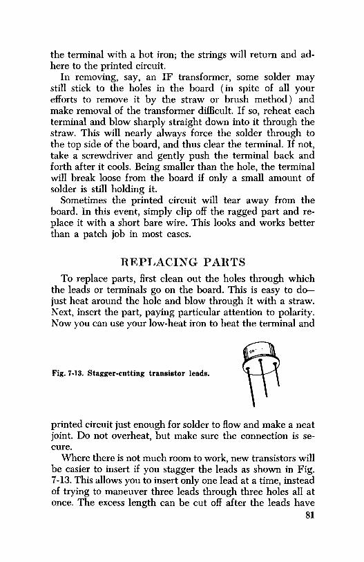
the terminal with a hot iron; the strings will return and adhere to the printed circuit.
In removing, say, an IF transformer, some solder may still stick to the holes in the board ( in spite of all your efforts to remove it by the straw or brush method) and make removal of the transformer difficult. If so, reheat each terminal and blow sharply straight down into it through the straw. This will nearly always force the solder through to the top side of the board, and thus clear the terminal. If not, take a screwdriver and gently push the terminal back and forth after it cools. Being smaller than the hole, the terminal will break loose from the board if only a small amount of solder is still holding it.
Sometimes the printed circuit will tear away from the board. In this event, simply clip off the ragged part and replace it with a short bare wire. This looks and works better than a patch job in most cases.
REPLACING PARTS
To replace parts, first clean out the holes through which the leads or terminals go on the board. This is easy to dojust heat around the hole and blow through it with a straw. Next, insert the part, paying particular attention to polarity. Now you can use your low-heat iron to heat the terminal and
Fig. 7-13. Stagger-cutting transistor leads.
printed circuit just enough for solder to flow and make a neat joint. Do not overheat, but make sure the connection is secure.
Where there is not much room to work, new transistors will be easier to insert if you stagger the leads as shown in Fig. 7-13. This allows you to insert only one lead at a time, instead of trying to maneuver three leads through three holes all at once. The excess length can be cut off after the leads have
81
been soldered. This method is also helpful for inserting other parts in cramped quarters.
HEAT SINKS Despite what you may have read or heard, in most in
stances you don't need a heat sink when soldering a transistor onto a printed board. The author personally has soldered hundreds of transistors and has yet to damage one. In fact, some have purposely been heated to the point where the set quit playing. But when they had cooled, the radio started playing again! Heat sinks? Most of these radios are so small that you couldn't get one to the lead of a transistor, even if you had to. However, in some instances, a heat sink might be desirable to protect the printed circuit from coming loose from the board.
REP AIRING BROKEN BOARDS Occasionally you will find a board that is cracked or even
broken in two. Rather than buy a new one, the best policy is to repair the old board. Epoxy cement, available from your distributor, is probably the best adhesive. However, it does have two disadvantages. It comes in two tubes, the contents of which must be mixed before use. Also, it is slow drying unless baked-and it isn't wise to bake a transistor radio!
Regular service cement will do a passable job if it is carefully applied and there isn't too much stress on the board. While cementing, you can hold the broken parts together with rubber bands, tape, string, alligator clips, or any other device that won't harm the board.
82

CHAPTER 8
Alignment and Tracking
Although alignment might be said to include tracking, we will use the term "alignment" here to mean peaking of the IF transformers, and the term "tracking" to mean adjustment of the RF and oscillator circuits in such a way that maximum gain is realized across the whole sweep of the dial. As an example of tracking, when the oscillator is tuned to 1005, 1355, and 1855 kc, the RF circuit ( s) should be resonant at 550, 900, and 1400 kc, respectively. This assumes the IF frequency is peaked at 455 kc. Unless a radio "tracks," it will be low in sensitivity at one end of the dial or in the middle.
Perfect tracking at every frequency is practically impossible, but you must have adequate tracking to insure maximum sensitivity in transistor radios. To help with tracking, the transistor radio usually has one more adjustment than a tube radio. This is an adjustable slug in the oscillator coil to vary its inductance, and is always set up at the low-frequency end of the dial.
The older method of tracking at the low end of the dial ( if the radio had a low-end adjustment) was to set the dial to receive a low-frequency station, and then to move it slightly in one direction and reset the low-end adjustment. If there was an improvement in the over-all output, the dial was moved slightly in the same direction, and the low-end adjustment again made. If there was no additional improvement or even an actual loss in output, the dial was moved back and the low-end adjustment remade. This trial-anderror tracking is called "rocking in," since the tuning capacitor and adjustment are rocked until maximum output is ob-
83

tained. Even though this method of tracking works, it requires considerable time and patience, in addition to an output meter and a fixed-signal source. Moreover, it may have to be repeated after high-end tracking is adjusted.
The method suggested below might well be called the "noise" method. It is fast and simple, and doesn't require elaborate test equipment. All you need is a small noise generator-either one of the several commercial models or ( as the author prefers) the noise from a fluorescent bench light. Here's all there is to the test-it often takes less time to do than to read the instructions.
84
1. Turn the radio dial to the low end ( near 550 kc ) . 2. Hold the radio close to the noise source, and turn the
volume all the way up. If the noise you hear in the speaker is too loud, move the radio further away from the source.
3. Adjust the oscillator trimmer ( across the tuning capacitor; Fig. 8-1) for maximum noise. If it occurs at one extreme of the trimmer, return the trimmer to about midway point. Then adjust the oscillator slug for maximum noise. ( Important, do not adjust the slug unless the oscillator trimmer peaks the noise at one extreme of its adjustment.)
4. Turn the radio dial to about 1400 kc. 5. Adjust the antenna trimmer for maximum noise, or for
maximum signal if a weak station is being tuned in. 6. If the antenna trimmer will not peak within its range,
set it near its midway point, and readjust the oscillator trimmer. If the noise now peaks, leave both trimmers at this point, turn the radio back to the low end, and adjust the oscillator slug for maximum noise. Now repeat Steps 4 and 5.
7. If the radio still does not track ( noise peaks cannot be obtained at both ends of the dial), check the IF frequency. Set the signal generator to the IF frequency and connect it to point A or B in Fig. 8-1. Using an alignment indicator, adjust the IF transformers for maximum output. Now repeat Steps 1 through 6. If the radio still does not track, then either an antenna coil, oscillator coil, or tuning capacitor is defective. Each can

ANTENNA TRIMMER
- / --• TOIF OSCl~LATOR .__ ___ ..,
TRIMMER
Fig. 8-1 Tracking adjustments in the mixer-oscillator.
be checked with a grid-dip meter, as explained in Chapter 2-or by direct substitution.
DIAL CALIBRATION During the alignment and tracking procedures, do not
worry too much about the dial readings being off, unless the discrepancy is large. Dial scales are mass-produced and not necessarily exact. If you try to make every radio track according to its dial reading, you will do so at the expense of sensitivity. In the procedure described, the dial ambiguity won't be great, but the sensitivity of the radio will be maximum.
PITFALLS OF TRACKING A few radios will not track unless the adjustments are
made with the battery in place. This is especially true if the battery lies alongside the antenna coil, as shown in Fig. 8-2A. ( It may butt against the ferrite core, as in Fig. 8-2B, without affecting the tracking.) Where the battery has an effect on the tracking, use the procedure outlined above but with the battery in place. (You need not power the radio from the battery, however, unless you prefer to do so.)
Another tracking problem is encountered when the antenna is mounted near metal parts and has to be removed
85

for servicing. As an example, the GE 716A antenna is housed alongside the metal case. To remove the set from the case, you must also remove the antenna from its housing. However, the antenna must be placed back into its housing before the set can be tracked.
ALIGNMENT INDICATORS The human ear is probably the alignment indicator used
most often. Because of its logarithmic nature of hearing,
ANTENNA COIL
BATTERY
( A) Battery mounted against antenna coil.
FERRITE STICK
( B) Battery mounted away from antenna coil.
Fig. 8-2. Respective positions of battery and antenna coil.
though, the ear isn't unfailingly accurate, but tends to "level off" changes in volume. On loud sounds the intensity must be doubled before the ear can discern any change. In spite of this, it is a fairly reliable indicator if volumes are low. Those who use "ear" indication learn to move adjustments rapidly 86

33.n.
.I MFD
+ 0-100
0-200 ' µA METER
Fig. 8-3. Output meter.
IN34 IN64 OR
EQUIV
back and forth past the peak so that they can "zero-in" the exact peak.
A much more reliable indicator is the output meter, which is merely an AC voltmeter with a capacitor in series to block any possible DC from the circuit. ( Most multimeters have a built-in output connection.) It is well worth your time to make up a set of leads, with an earphone plug on one end, and simply connect your output meter to the earphone jack.
You can build your own output meter, using the circuit in Fig. 8-3. Here, the 33-ohm resistor provides a DC path in circuits where it is needed. Fig. 8-4 shows a combination output meter and test speaker. While the speaker is in use, the control should be turned down to protect the meter from damage. In all alignment and tracking procedures, the radio volume control should be set at maximum, and the signal input kept at the lowest point that will still provide a usable indication on the output meter or other indicator.
Another good alignment indicator is the tuning eye or meter that is an integral part of your signal tracer. These devices are extremely sensitive, since they measure the signal
EARPHONE PLUG
.I MFD
5K CONTROL
0-100 OR
0-200 µA METER
Fig. 8-4. Output meter with speaker.
IN34 IN64 OR
EQUIV
87

after it has been amplified by both the radio and signal tracer. The advantage of this type of indicator is that it can be connected almost anywhere in the signal path and still provide a usable reading.
As with tube radios, the AGC voltage can be measured with a VTVM to obtain an output indication. This doesn't work as well as with tube radios, however, since the voltage change is small, but it can be done if the DC scale is 1.5 volts or less. The advantage of the AGC voltage is that it is usually across the volume control, where it is easy to measure.
If you are using a separate metered power-supply source, and if the set has the usual class-B output stages, you can align the set by watching the current meter. As the signal increases, so will the current drain of the set, and you simply peak the circuits for maximum current drain. This method is unsatisfactory for peaking a broadcast station signal, but is ideal for a noise- or tone-modulated signal.
SEALED ALIGNMENT SCRE,vs
Several manufacturers use a plug to seal the IF and oscillator slugs. A needle or a small ice pick can often be sunk into the wax at an angle and the whole plug lifted out. At other times, it will have to be dug out in pieces.
Resealing You can re-use the wax plug by laying it over the hole in
the can and heating it with a soldering iron. Otherwise you can use paraffin wax, available at grocery stores. Shave off a small piece, lay it on top of the IF transformer or oscillator coil, and touch it with a hot iron. The paraffin will run down around the slug, and form a seal as it cools. Paraffin is also ideal for holding wires in place across a printed board. It may also be used to hide and protect a repair to an antenna coil.
Ho,v OFTEN ARE ALIGNMENT AND TRACKING NEEDED?
When to do alignment and tracking is a question of judgment. It is suggested that tracking be checked as part of 88

any repair job. If the IF transformers are still sealed, and if the sensitivity seems good, then alignment probably won't be necessary. But tracking with the noise method can be checked in less than a minute, and often results in a much more sensitive radio.
89

CHAPTER 9
Repairing the "Weak" and
"Not Quite Right" Radios
In transistor radios that appear to be "not quite right," it is recommended that you bypass every electrolytic in the set with a known good one as a preliminary to further checking. Assuming the radio has not been tampered with, defective electrolytics probably account for more than 75% of "weak" radios. But how can you find other "weaknesses" in the radio? The answer is, "you can't," except by accident, unless you have some reference to go by. This is where signal tracing is virtually indispensable.
SIGNAL TRACING The signal-tracing technique requires that you have a
signal tracer that indicates relative signal output. A speaker is not a satisfactory indicator when you are checking a weak radio, since human hearing is an unreliable judge. The indicator may be of the meter or tuning-eye type with some sort of calibrated attenuation. Some techniques are quite successful in using a scope as a signal tracer; others are fortunate enough to own one of the older, tuned signal tracers. Most of today's tracers are untuned and are simply high-gain audio amplifiers that usually employ a diode or grid-leak detector for RF detection. They work all right with a strong local signal, but if the signal is weak you may not hear anything until you touch the collector of the first or second IF. No matter what kind of tracer you use, the signal must be taken off the collector circuit, where the impedance is high. Unless the signal is extremely strong, you will get no reading from a 90

base circuit, because most tracers respond to voltage changes and there are mostly current changes in the base circuit.
A signal tracer can be a valuable aid if you are familiar with its idiosyncrasies and shortcomings. Nearly every tracer will exhibit some pecularity at times, such as causing the stage to oscillate while you are trying to test it. ( Signal tracers are discussed in more detail in Chapter 11.)
The secret of finding weak radios with a signal tracer is in first checking several sets that are not weak. Select a moderately strong broadcast station in your area, ( one not so strong that it blocks the set's AGC, nor so weak that its signal varies in strength). Fig. 9-1 shows a schematic of a popular six-transistor radio. Using it as a guide, check the gain of several radios, all tuned to the same station. ( Make sure the antenna is oriented to receive maximum signal.) At the various points marked on this schematic, write down the amount of gain for each set. Once you have established these references, localizing a weak stage in any of the many radios on the market will be easy.
Some tracers are not sensitive enough to recognize a signal at point A in Fig. 9-1, but it is advantageous to have one that does. A sensitive tracer will immediately determine whether or not the antenna loop is peaking at the correct frequency. Use a low-frequency station ( if possible) for this test, since the capacity of the tracer probe will have less effect on the dial calibration. If the signal can be peaked near the point on the radio dial where it should be maximum, then the loop-antenna coil and capacitor are OK. ( The base coil can be checked with an ohmmeter.) If the IF signal is weak at point Bin Fig. 9-1, check for trouble in the mixer-oscillator stage. Sometimes this weakness is caused by inadequate oscillator injection voltage, especially when a separate oscillator stage is used. Use a grid-dip meter to inject signal directly into the loop, as explained in Chapter 11. If the signal strength becomes stronger, then check for an open coupling capacitor in the oscillator circuit.
Point E is the last test point before detection. However, either point D or E may be used as the final reference. There will be more signal available at D than E, but in some sets this circuit will oscillate when a signal-tracer probe is touched to it. It is suggested that both points be used as a
91

TO
92
5000 MMF
~ -'~
30K
30 MFD
.--.--t-------~--,----1 5.6K
2.2K
.._------+--------+---+---C SOK ._ ________ _. __ ,._ ______ ._ _______ ..... _..,.. ___ D
COLOR DOT COLLECTORV
BASE:::y
EMITTER
BOTTOM VIEW TRANSISTOR
0 3 2
BOTTOM VIEW OSC COIL
0 BOTTOM VIEW
L3,L4,SL5
Fig. 9-1. Schematic of Channel Master
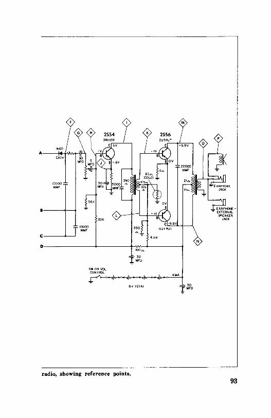
•------4,-....
C-----~
D---------+------hNv----+-----•
SW ON VOL CONTROL
100.n..
• 30
::tMFO
r---0-¥---¥--¥---.i -GV TOTAL
radio, showing reference points.
4"1A
• 30 I MFO
N
aHONE-- EXTERNAL
SPEAKER JACK
93
reference, since this will also give you some idea of the condition of the last IF transformer.
In signal tracing, excessive signals can have at least two causes. First, if your tracer does not have a speaker output the circuit under test may be regenerating. Second, a defective diode detector may not be supplying enough ( if any) ACC. Of course. a shorted or leaky AGC capacitor could cause the same trouble, but this is unlikely since the normal DC bias would be upset. Usually, a leaky or shorted AGC capacitor causes a weak or dead radio.
AUDIO STAGE GAIN To check the gain of an audio stage, connect a constant
tone audio generator and a signal tracer to point F. Inject a not too strong signal and note the reading of the tracer. This is your reference input signal. Now, with the volume control at maximum, move the tracer to points G and H in succession. Both should have almost the same indication as point F. Take reference signals at H, I,], K, L, M, N, 0, and P, and jot them all down. The signal at point J should be almost zero. If, at any time, there isn't enough signal at point I, always check point]. Too much audio at/, indicates the electrolytic bypass is open.
This takes care of the reference signals. You'll find that the gain of each stage will not vary too much between different radios of good design. These reference signals should be taken with five or six different radios. Make sure that all are in good working order and that at least one or two have excellent sensitivity so the reference readings will reflect the best that can be expected.
IS IT THE DESIGN? Some transistor radios just won't measure up to even aver
age performance. You may find a six-transistor radio that won't play as good as a five-transistor set. This is usually due to poor design or poor quality transistors, or both. Older radios, especially, suffer from less refined designs and less sensitive transistors. Their sensitivity will be low and the noise level high. In certain midget radios, the battery is mounted 94
alongside the antenna coil. This always lowers the radio sensitivity because the Q of the antenna is reduced. Frequently, though, poor design isn't easy to spot. Until you become familiar with several radios of the same model, you may not be quite sure whether a defect or "poor" design is to blame.
IF transformers in older radios often cause low sensitivity. Occasionally inserting a couple of new-style IF transformers will do wonders in an otherwise listless radio, but simply replacing the transformers with the same types will do no good at all.
Sometimes improvement can be obtained by changing to higher-gain transistors. However, this isn't always true. The difference between the dynamic impedances of the old and new circuits may offset any additional transistor gain. As a result, the circuit may oscillate unless some sort of neutralization is provided.
HINTS ON IMPROVING PERFORMANCE
If the customer complains that the radio is weak, it is often possible to milk a little extra sensitivity from an inherently sluggish set, or from one made weak through deterioration of its parts.
Biasing-Sometimes the performance of the radio can be improved by juggling the IF or mixer bias slightly. A lOOK control in series with a 3.3K resistor is ideal for checking this, as shown in Fig. 9-2. Clip one end of the control to the "hot" side of the battery, and momentarily touch the resistor side to the base of the transistor under test. If there is not noticeable improvement in performance at any setting of the lOOK control, clip the control to ground and again apply the 3.3K probe to the base. If there is any improvement with either arrangement, check for leaky bypass or coupling capacitors. Also check for a bad transistor.
Audio Driver - Occasionally, replacing the audio-driver transistor with a high-gain type will make a remarkable difference in speaker output. Often the universal replacements recommended for the audio stage are "culls" that are notably lacking in gain. In such a case, use a converter or IF type as a replacement.
95
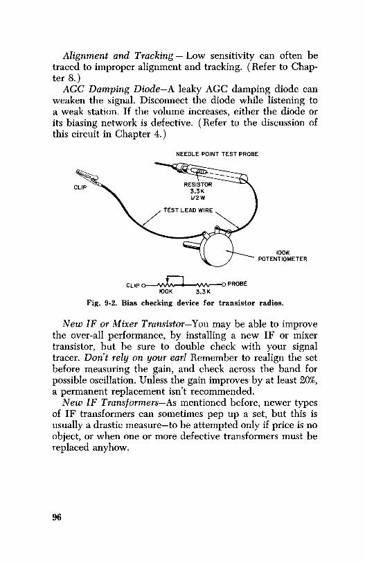
Alignment and Tracking - Low sensitivity can often be traced to improper alignment and tracking. ( Refer to Chapter 8.)
AGC Damping Diode-A leaky AGC damping diode can weaken the signal. Disconnect the diode while listening to a weak station. If the volume increases, either the diode or its biasing network is defective. ( Refer to the discussion of this circuit in Chapter 4.)
NEEDLE POINT TEST PROBE
CLIP~ PROBE IOOK 3.3K
IOOK POTENTIOMETER
Fig. 9-2. Bias checking device for transistor radios.
New IF or Mixer Transistor-You may be able to improve the over-all performance, by installing a new IF or mixer transistor, but be sure to double check with your signal tracer. Don't rely on your ear! Remember to realign the set before measuring the gain, and check across the band for possible oscillation. Unless the gain improves by at least 20%, a permanent replacement isn't recommended.
New IF Transformers-As mentioned before, newer types of IF transformers can sometimes pep up a set, but this is usually a drastic measure-to be attempted only if price is no object, or when one or more defective transformers must be replaced anyhow.
96

CHAPTER IO
Noise, Oscillations,
Squeals, and Motorboating
Two of the most provoking problems in transistor radio servicing is noise and oscillations. Inability to localize the problem is often the main obstacle to rapid repair. This chapter will present some tried procedures for quickly locating defective circuits.
NOISE
Noise can be either static-like crashes in the speaker, or a steady rushing sound somewhat like that heard between stations on an FM set.
Noise ( if it isn't static) is usually caused by leaky capacitors, battery electrolyte on the printed board ( to be discussed later), and on occasion by a defective transistor or transformer in transistor radios. On the other hand, in tube radios the noise nearly always originates from a defective transformer, and on occasion from a resistor.
The low-voltage capacitors used in transistor radios seem unusually prone to break down. How to isolate the trouble to a particular stage can perhaps best be illustrated by the following example. Assume the radio emits a static-like noise from the speaker, but may or may not receive a station. Also assume that the noise disappears when the volume is turned down. This, of course, means that the noise is occurring before the audio stages. Take a piece of wire and short between the base and emitter of the second IF, the first IF, and the mixer-oscillator transistor. Suppose each time you do this, the noise stops. Since the radio has no RF stage, the noise must be some sort of intederence actually being picked up by the
97
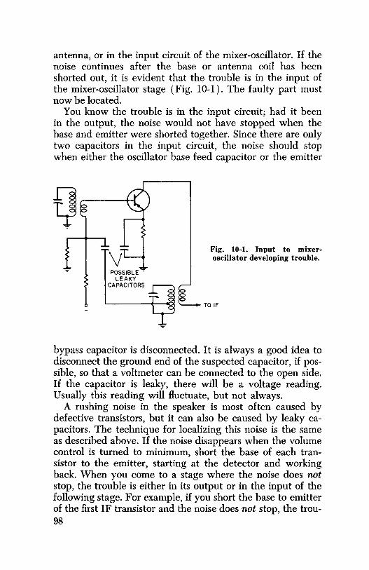
antenna, or in the input circuit of the mixer-oscillator. If the noise continues after the base or antenna coil has been shorted out, it is evident that the trouble is in the input of the mixer-oscillator stage ( Fig. 10-1). The faulty part must now be located.
You know the trouble is in the input circuit; had it been in the output, the noise would not have stopped when the base and emitter were shorted together. Since there are only two capacitors in the input circuit, the noise should stop when either the oscillator base feed capacitor or the emitter
Q POSSIBLE""'"
LEAKY CAPACITORS
Fig. 10-1. Input to mixeroscillator developing trouble.
TO IF
bypass capacitor is disconnected. It is always a good idea to disconnect the ground end of the suspected capacitor, if possible, so that a voltmeter can be connected to the open side. If the capacitor is leaky, there will be a voltage reading. Usually this reading will fluctuate, but not always.
A rushing noise in the speaker is most often caused by defective transistors, but it can also be caused by leaky capacitors. The technique for localizing this noise is the same as described above. If the noise disappears when the volume control is turned to minimum, short the base of each transistor to the emitter, starting at the detector and working back. When you come to a stage where the noise does not stop, the trouble is either in its output or in the input of the following stage. For example, if you short the base to emitter of the first IF transistor and the noise does not stop, the trou-98
ble is in either the collector circuit of the first IF or the input circuit of the second IF. Usually a new transistor will cure the trouble.
INHERENT NOISE All transistors have inherent noise in different degrees. The
later-model radios with newer transistor types usually have less noise than older radios. As with tube receivers, the test of a good transistor radio is its signal-to-noise ratio-in other words, how much inherent noise you hear when the radio is tuned to a weak station. The less the noise, the better the signal-to-noise ratio. Older radios can often be improved in this respect by installing newer type transistors. However this is a drastic measure not suitable to most customers' purses.
SQUEALS, OSCILLATIONS, AND MOTORBOATING
The term "squeals," "oscillations," and "motorboating" are often used interchangeably, depending on the frequency of the oscillations. High-frequency oscillations are usually referred to as squeals, and low-frequency ones as motorboating.
The two most common causes of oscillations are open and leaky bypass capacitors, usually electrolytics. As previously explained, the best and fastest way to find an open bypass is to shunt each one with a known good capacitor. A 20-mfd, 15-volt unit is suitable for any bypass testing. Since the printed circiut i,s nearly always accessible when the back of a transistor radio is removed, this method is fast and eff ecti ve, even on a strange model. First determine which side of the battery is tied to ground. Next, attach one side of the test electrolytic to ground ( be sure to observe the polarity), and move the free end to each connection on the printed board. When you reach the defective capacitor, the radio will start playing. This method may sound crude, since you are pretty much "flying blind" by bypassing connections that normally are not bypassed, but it doesn't take long. In fact, you may be able to find the trouble without having to remove the set from its tightly fitted case. Once you find the
99

trouble, you'll have to remove the case anyway, to repair the set-but you won't mind as much, since you already know where the trouble is.
If bypassing capacitors doesn't stop oscillations, then you need to isolate the off ending stage or stages even further. This can often be done by lowering the gain of suspected stage. If the oscillation stops, you are close to the trouble. The simplest method of lowering the gain in RF mixers and IF stages is to load the stage with a resistor. For example, if you suspect an IF stage of oscillating, place a lOK resistor across the IF transformer, as shown in Fig. 10-2. If the oscillation stops, it's a good bet that the trouble is either in that stage or the one following it. Remember, though, that
IOK TEST RESISTOR
Fig. 10-2. Lowering the gain by loading the circuit.
a resistor across the transformer is not a cure. Even if it stops the trouble, it has only done so by reducing the gain of the stage. Leaving the resistor in permanently will lower the sensitivity of the set. The only cure is to find the trouble and fix it.
It is not unusual for a transistor itself to cause oscillations. If you suspect that it is, use the "razor blade" technique described in Chapter 7 to temporarily try a new one. Be sure to repeak the IF transformers, however, before assuming that the trouble is fixed; the new transistor may simply have detuned the IF ( lowered the gain) to the point where the oscillations cease. The radio, if it is well designed, should not oscillate at any peak setting of the IF transformers. As a proof test, you will find that a transistor which oscillates in the circuit will nearly always have excessive leakage when tested on a transistor tester. 100

Other causes of oscillation were discussed in Chapter 2. Among them were defective neutralization, open IF capacitors, and an open antenna coil.
If turning the volume down does not stop the oscillations the trouble must be in the audio circuits. As in other stages, it can be caused by open electrolytics, especially those on the battery supply line.
Oscillations may also be caused by incorrect phasing of a replacement transformer, where inverse feedback is used. ( Inverse feedback becomes regenerative feedback when the phase is reversed.) The cure is to reverse the leads on either the primary or secondary of the transformer-but not on both!
RCA models using a tapped voice-coil speaker will oscillate when one side of the voice coil is open. Refer to the discussion on this in Chapter 5.
The most common source of audio oscillations in transistor radios is a defective battery. Most of them do not have an electrolytic across the battery. Hence, if the internal resistance of the battery is high ( usually due to being run down), the radio will likely motorboat.
It is not uncommon for a radio to motorboat on an electric power supply, yet work all right on batteries. That is why Chapter 11 recommends a low-impedance power supply. If your power supply causes motorboating in some sets, you may be able to improve its performance by installing a 1,000-mfd capacitor across its output terminals.
Battery holders sometimes give the same troubles as noted above for batteries when the contacts become excessively corroded due to a leaky battery. This corrosion forms a high resistance that prevents the battery from doing its required job of filtering. If the corrosion is not too severe, a vigorous cleaning may be sufficient. Otherwise, the battery holder should be replaced. However, you can sometimes scrape the contacts clean with a knife or sandpaper until they will take solder. A coating of solder will make a good contact surface, and the repair is likely to be satisfactory.
BATTERY ELECTROLYTE
Battery electrolyte can cause no end of trouble when deposited on a printed board. The symptom may be a staccato
101
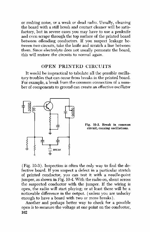
or rushing noise, or a weak or dead radio. Usually, cleaning the board with a stiff brush and contact cleaner will be satisfactory, but in severe cases you may have to use a penknife and even scrape through the top surface of the printed board between offending conductors. If you suspect leakage between two circuits, take the knife and scratch a line between them. Since electrolyte does not usually permeate the board, this will restore the circuits to normal again.
OPEN PRINTED CIRCUITS
It would be impractical to tabulate all the possible oscillatory troubles that can occur from breaks in the printed board. For example, a break from the common connection of a number of components to ground can create an effective oscillator
T T ,l BREAK
+
Fig. 10-3. Break in common circuit, causing oscillations.
( Fig. 10-3). Inspection is often the only way to find the defective board. If you suspect a defect in a particular stretch of printed conductor, you can test it with a needle-point jumper, as shown in Fig. 10-4. With the radio on, shunt across the suspected conductor with the jumper. If the wiring is open, the radio will start playing; or at least there will be a noticeable difference in the output. ( unless you are unlucky enough to have a board with two or more breaks).
Another and perhaps better way to check for a possible open is to measure the voltage at one point on the conductor, 102

Fig. 10-4. Needle-point jumper.
15" PIECE OF TEST LEAD WIRE
NEEDLE POINT TEST PROBES
and then at a different point on the same conductor, as shown in Fig. 10-5. Even the slightest difference in voltage means the conductor is open. If the suspected conductor is ground or common, place the other lead of the voltmeter to the "hot" side of the power supply. There are conceivably times when the voltmeter method would not find the trouble, but it is fast and almost infallible-try it.
Some might ask "Why not use an ohmmeter?" Personally, the author prefers the voltage method, since it is performed with the radio on. The pressure of a test probe will often heal a circuit. If the radio is on, you can hear any such change in the speaker, However, this would not be true while using an ohmmeter with the radio off. Many times, when oscillation is the problem and the presence of a test probe on the circuit stops the oscillation, the very presence of the probe helps localize the trouble.
Fig. 10-5. Troubleshooting an open circuit with a voltmeter.
103

CHAPTER 11
Tools and Equipment
A service technician cannot repair transistor radios at a profit without the appropriate test equipment. However, just having the equipment isn't enough; the technician must know its specifications and understand its uses. The average radio and TV shop usually has some of the necessary equipment to repair transistor sets, but not all of it. It is suggested that a special bench be set up for the service of transistor radios. This will pay big dividends in the long run. The bench might double as a tube-radio service center also, depending on the expected volume of sets to be repaired.
EQUIPMENT NEEDED
The one essential extra piece of equipment needed is a low-impedance power supply with a 0-50 or 0-100 milliammeter. By a low-impedance supply is meant one that will power any transistor radio without causing it to motorboat or squeal. Not every commercial power supply has this capability! If the milliammeter used in series with the supply is not of the low-impedance type, it must be bypassed with a large capacitor to prevent it from affecting the circuit.
Another feature the power supply should have is one or more voltage taps. Several transistor radios have three connections to the battery supply. In this case, a two-terminal power supply cannot be used.
Regulation of the power supply need not be exceptional. If it meets the requirement of low impedance, it will suffice as to regulation. Even 61/2 to 7½ volts delivered to a 6-volt radio is not likely to damage it. If the radio is harmed, chances are it needed repairs anyway. 104

Many shops have DC power supplies for testing automobile radios. Although these will work quite well for twoterminal testing, they have no taps, and the current meter is too insensitive to be of value. The voltage-divider circuit in Fig. 11-1 can be added easily to this sort of power supply and its usefulness increased immeasurably. Notice that setting the output of the supply to 9 volts will supply all the other taps with the correct voltage. Since the current through a radio is small compared with the bleeder current, the voltages will easily stay within acceptable tolerances. This volt-
• ~ • OFILTERED
6-12V DC + POWER SUPPLY
TO AUTO RADIOS __ __. __
0-50 0-100 \
MA METER
20.n. OR LESS DC RESISTANCE
+9V
1000 - MFD
IOV
+7-l/2V +6V
5.n. IW
+4-l/2V +3V
+ l-l/2V
Fig. 11-1. Converting a battery eliminator into a transistor-radio power supply.
-ov
age divider may be built in a small box, and the meter permanently attached to the power supply. The 5-ohm, 1-watt resistors can be two 10-ohm, ½-watt resistors in parallel. The meter can be an inexpensive moving-vane type with an impedance of 20 ohms or less, or it can be a D' Arson val type if the shunt used reduces the impedance to 20 ohms or less.
Several companies make power supplies with built-in meters that meet all the requirements listed above. Some companies even have power supplies incorporated with other test instruments. After reading the rest of this chapter, you can decide which type best suits your needs.
105

Signal Tracers Before the days of TV, when tube radios were in their
heyday, several companies built and sold elaborate tuned signal tracers. If you're lucky, you may be able to resurrect one of them for use on transistor radios. The tuned tracer has several advantages over present-day untuned types. One is that their high-gain, high-impedance input makes the loading on the tested circuit almost negligible. Another is that they usually have provision for monitoring the oscillator circuit, not only for the presence of oscillations, but for their frequency as well.
Fig. 11-2. A test probe will load the tuned circuit if
placed on point A.
Today most tracers consist simply of a high-gain audio amplifier with some method of RF detection, usually a diode, in the probe. Of course, these tracers work better in areas of strong broadcast signals than in fringe areas. To be of real value, a tracer should be able to pick up a broadcast signal at the collector of the mixer with enough power to make a fair indication on the tuning eye or the meter. It is even better if you can pick up the signal from point A in Fig. 11-2, so you can determine whether or not the antenna circuit is tuning to resonance. Don't forget, though, that all tracers have some capacitive loading, which will be effectively in parallel with the tuned circuit, so the receiver dial will read high in frequency. The ideal place to pick up this signal is at point B. Unfortunately, unless the signal is extremely strong, there is not enough voltage developed at this point to activate the tracer.
If you service radios in a weak-signal area, you can build your own broadcast signal source by attaching an open loop to your signal generator, as shown in Fig. 11-3. With this 106

arrangement you have a fairly reliable source of signal that is relatively unaffected by its environment. The generator must be set for some specified output to which it can easily be reset. This is easily done by setting the variable vernier dial of the generator to maximum and using the step attenuator to arrive at the desired signal strength. Once this setting is obtained, you should always use it. This will give you a
3/8" ALUMINUM TUBE BENT INTO 13"
DIAMETER
3 TURNS ltl8 WIRE
LEAD FROM SIGNAL GENERATOR
Fig. 11-3. Radiant loop for a signal generator.
good idea of just how much gain to expect at a certain point in your signal-tracing procedure. This is especially useful when you are tracing a weak radio, as outlined in Chapter 8.
The Oscilloscope
A scope can be used as a signal tracer if its response is fairly flat throughout the broadcast band. However, since much information can be obtained from tracing at the IF frequency, a scope response that is reasonably flat to 500 kc is adequate for most purposes. The scope should have high gain so that the tracing may be done with a low-capacity probe to minimize loading of the circuit being tested.
The scope has the disadvantage that you cannot hear the signal under test; so you can't be sure which station is being monitored. Also, it is harder to make gain measurements using a station signal, because of the modulation patterns on the scope. However, after you have had a little practice, these disadvantages will present no great problems.
107

You can, of course, use a signal generator as a signal source and turn off the modulation, if desired, so you will always know the frequency of the incoming RF signal. When you are tracing with a scope, probe loading effects might create oscillations. Since you don't hear the signal, you may be misled as to the actual gain of the stage under test. Hence, if there seems to be a discrepancy in the reading, make sure the signal you are seeing is none but the one you are actually feeding in!
Signal Generators Two general types of signal generators are used in tran
sistor-radio servicing. One is the standard RF generator with or without audio modulation. The other is the untuned, or so-called noise, generator. The standard RF signal generator with good attenuation is far more satisfactory than the untuned type. The RF generator can be used to align circuits to their proper frequencies; to broadcast a reference signal for signal tracing; and, with some models, to check the gain of the audio stages.
On the other hand, the noise generator-which is nothing more than a pulse or spike generator that shock-excites a resonant circuit into oscillation-is much harder to control. Many of them have no provision for controlling the signal output. Even those that do often seem to suffer from inadequate control, and without control, the noise generator is virtually useless except perhaps in the hands of a most skilled technician. It is not unusual to place a noise generator on the ground return of a dead stage and still get a shrill tone from the speaker - sometimes even with the volume turned down. Needless to say, this doesn't present much information about the condition of the radio.
The noise generator is a useful tool in low-end tracking because there is no need to "rock" the tuning capacitor. But even here, a fluorescent desk lamp does just as well. ( Ref er to the alignment procedures in Chapter 8.)
Noise generators with attached ground wires and shielded output leads seem to work better than the "pencil" types. One noise generator radiates a signal from a built-in ferrite antenna and is ideal for tracking adjustments if it is placed several feet from the radio under test. 108

Transistor Tester
A good out-of-circuit transistor tester is desirable, although perhaps not absolutely necessary. The author recommends one that has at least 4½ volts between the collector and emitter during the leakage test, and preferably more. Because of excessive leakage at higher voltages, it is not unusual for a transistor to test "good" on 1 ½ or 3 volts and yet refuse to play in a 6-volt radio. In-circuit transistor testers are covered in detail in Chapter 7.
Grid-Dip Meter
One of the most useful tools for checking the front-end of a transistor radio is a grid-dip meter. It is simply an oscillator in which its tank coil is mounted as a "probe." A DC microammeter in the grid circuit of the oscillator indicates the relative oscillator power. When the probe is brought close to a tuned circuit that is resonant with the oscillator, the circuit absorbs power from the grid-dip oscillator ( GDO), and the meter in the grid circuit registers the loss of power by dipping (decreasing). Making the oscillator variable lets you sweep it across a band of frequencies until a dip occurs. Since the GDO is calibrated in frequency, the dial reading at the dip indicates the frequency of the resonant circuit to which the probe coil is inductively coupled.
For transistor radios you can tell whether the antenna coil is open or the tuning capacitor is defective by simply holding the GDO probe near the ferrite antenna, as shown in Fig. 11-4. The frequency reading on the GDO dial should be approximately that indicated on the radio dial. The oscillator circuit can be checked in the same manner, if the oscillator coil is unshielded. The GDO should read approximately 455 kc ( the IF frequency) higher than the dial setting of the radio.
You can monitor the radio oscillator by simply plugging high-impedance earphones or an amplifier into the GDO. This disables the meter, but when you tune the GDO to the approximate frequency of the radio oscillator, you will hear a beat frequency (tone). As the two oscillators approach the same frequency, the tone will drop in pitch and finally zero beat (null).
109

Another and sometimes faster way to check the oscillator is to set the dial of the radio near a strong station. Now bring the GDO near the antenna coil, and set the GDO dial to the IF. For example, if the broadcast station is at 1,000 kc, set the GDO to 1,455 kc. The station should come in loud and clear, if the radio oscillator circuit alone is at fault. The GDO coil should be kept within one inch of the antenna coil during this test.
Fig. 11-4. Checking an antenna loop with a grid-dip oscillator.
When choosing a grid-dip meter make sure its coils and dial are calibrated down to 455 kc or below. Many are made for high frequencies only, starting above the broadcast band. Recently, at least two kit or wired meters-the EICO Model 710 and the PACO G-15-W-have been introduced that go down to 400 kc.
The V alt-Ohm Meter The volt-ohm meter can be either a 20,000-ohms-per-volt
meter or a VTVM, and preferably should have a low-range DC scale of 1.5 volts or less. The ohmmeter should have a good low-resistance range so that resistances of only a few ohms may be read accurately. Needle-pointed test leads will enable you to pierce printed-circuit coatings. Special leads equipped with steel phono needles can be purchased, or you can solder a sewing needle to existing probe tips. 110

Other Equipment As was pointed out in another chapter, you should have a
speaker with an attached earphone plug, which can be inserted into the radio earphone jack for a quick check of it and the speaker. An output meter on another earphone plug makes an ideal alignment indicator, by the way.
In the way of hand tools, you need a small stiff brush and a collection of plastic soda straws for removing solder ( refer to Chapter 7), and a tool for removing earphone nuts. This
Fig. 11-5. Earphone nut remover made from a screwdriver.
tool can be made from a large inexpensive screwdriver. File the blade as shown in Fig. 11-5, using an earphone nut as a pattern.
Additional special tools you will need are small nut drivers %2, ½, and %2, in addition to the regular sizes, up to % ) , small long-nose pliers and diagonal cutters, and a small- and medium-size soldering iron or gun. Also, a magnifier ( which may be built into your fluorescent bench lamp), alignment tools, and small regular and Phillips screw drivers.
SCHEMATICS AND SERVICE INFORMATION
There is perhaps no other field of electronic servicing where schematics and service information are more important than in transistor radios. One reason is that there are so few guide points for circuit tracing. There are no tube sockets; the transistors themselves are almost always wired in. IF transformers have no particular wiring order. Parts are so crowded together that it is often hard to even see all the leads, much less tell where they go. So, in addition to a schematic ( which is essential, since hardly any two models
111

are alike), the proper test points must be called out. Otherwise, what might have been turned into a profitable job turns out instead to be an infuriating guessing game. Of course, experience eventually helps, but takes a long, long time unless you are working only on one or two models ( a highly unlikely situation).
PARTS SUPPLIES
A well-equipped service shop will need an assortment of small resistors and capacitors for use in susbtitution testing and as replacements. Fig. 11-6 shows how a component may be soldered to a terminal strip with test leads attached. This
Fig. 11-6. Building a test component setup.
setup makes the substitute testing easier and also prevents component leads from being broken in two by the continual bending back and forth during testing.
You can purchase complete kits of low-voltage electrolytics at most distributors, as well as capacitor assortments and the like.
You must have an assortment of PNP and NPN transistors. These are also furnished in kits. However, the transistors in some kits sold only on the basis of price will not perform as well as others. So select your test transistors with care. If possible, have at least two or three of each type available for every stage in the radio.
A converter transistor will work as an IF, RF, or AF driver and often as a class-B audio output if its voltage rating is not exceeded. If transistors will also work as audio drivers and 112
class-B audio outputs, and sometimes as converters of RF amplifiers, too.
A cabinet with about fifty drawers or compartments should hold all the small parts and metal hardware ( bolts, nuts, dial screws, dial plates, etc.) you need to start servicing transistor radios.
A word of advice: Don't try to get along with inadequate or inferior equipment-you will pay for your shortsightedness in lost profits. The difference between a busy shop humming along making a profit, and one that is losing its shirt, is often a matter of which shop is better equipped.
Incidentally, for cleaning transistor cases and knobs, nothing is better than warm ( not hot) water, a mild detergent, and a tooth or denture brush for getting into the crevices. Don't use a brush with plastic bristles; they will sometimes dull the finish of the case. Flush away all the detergent with cool water, and dry thoroughly with a cloth-any water droplets may damage the speaker when the chassis is returned to the case.
113

CHAPTER 12
Where to Get
Replacement Parts
At the present time one of the big problems in servicing transistor radios, especially foreign ones, is obtaining replacement parts. More than seventy brand names have been imported into the United States in recent years, and only a few of these companies have nationally advertised parts agencies. The others mt'lst be contacted by writing directly to the importer. A list of Japanese importers is included at the end of this chapter.
Sometimes the technician or customer may not want to wait two or three weeks for an exact replacement part. Although exact replacements are always recommended, it is possible to substitute many of the parts in transistor radios. As a general rule, nearly any part that doesn't have an insurmountable mounting problem can be substituted. The following discussion of replacement parts should help you decide whether the substitution is feasible or profitable.
Loopstick Antenna-Perhaps no part is more difficult to substitute than a loopstick antenna, since it usually presents both a mounting and an electrical performance problem. A larger loopstick can be replaced with a smaller one of the same inductance, but only at the risk of loss in sensitivity that may or may not be objectionable to the customer.
Broken loopsticks usually cannot be repaired since the breaking impact generally changes the characteristics of the core material and thus the inductance. In this event it is useless to glue or otherwise try to repair the core material.
If the coil itself is damaged you can rewind it, using a low-frequency grid-dip meter to determine when you have enough turns. This is not recommended unless you have the 114

time and the customer is willing to pay for the job. The base coil is not too critical and is usually about 7 to 15 turns. Remember that in some radios the inductance of the antenna may be affected by its proximity to other parts. Therefore, having rewound it, you must have the antenna in its mounted position when checking with the grid-dip meter. The antenna will not exhibit too large a proximity error if kept more than a half inch from small or one inch from large metal parts.
Fig. 12-1. Feedback from collector to base.
LOOPSTICK
0 .05
O~'~TOIF
~ RCOIL
If the replacement can be mounted, check the inductance with the grid-dip meter. If it is correct, connect the loop to the tuning capacitor of the radio, and set the dial to about 550 kc. With the grid-dip meter, see whether the circuit is resonant to approximately this frequency. Check again at 1,400 kc; if the circuit is resonant here also, then it will probably track properly in the radio.
Oscillator Coils-Most Japanese oscillator coils are of the same inductance. There are two physical sizes, miniature and subminiature. Also, there are two feedback circuits, base and emitter ( Figs. 12-1 and 12-2). This means that by reversing the primary winding, it is possible to use the same oscillator coil for either type of feedback. However, reversing the primary winding can be a problem in working with printed cir-
115
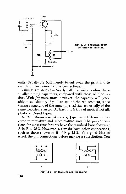
PNP LOOPSTICK
1.5K
tli.05
--+-- TOIF
-,,,. CCOIL
Fig. 12-2. Feedback from collector to emitter.
cuits. Usually it's best merely to cut away the print and to use short bare wires for the connections.
Tuning Capacitors - Nearly all transistor radios have smaller tuning capacitors, compared with those of tube radios. With Japanese units, however, the capacity will probably be satisfactory if you can mount the replacement, since tuning capacitors of the same physical size are usually of the same electrical size too. At least this is true of most, if not all, plastic enclosed types.
IF Transformers - Like coils, Japanese IF transformers come in miniature and subminiature sizes. The pin connections for most transformers have the standard base shown at A in Fig. 12-3. However, a few do have other connections, such as those shown in B of Fig. 12-3. It's a good idea to check the pin connections before making a substitution. You
A B
Fig. 12-3. IF transformer mounting.
116

can often substitute an A for a B type by drilling a small hole in the printed board to accommodate the odd pin. If necessary, the odd pin can be connected into the circuitry with a piece of bare or insulated wire.
Most Japanese IF transformers can be interchanged with another of the same type. That is, a first IF for another first IF, etc. There is one precaution to observe, however. Sometimes the first IF has the capacitor built in and sometimes it is externally mounted.
Volume Controls and Switches - In transistor radios the most common controls are 5,000-ohm units. Generally, no difficulty is encountered in replacement, except perhaps in mounting them.
Audio Transformers-Audio transformers are almost universally interchangeable unless there is a mounting problem.
Speakers-Speakers usually present a mounting problem only. Most Japanese radios have low-impedance speakers. On the other hand, some American speakers have impedances of 100 ohms or more, and still others are center-tapped.
Transistors-Several companies now supply universal transistor kits. Usually these work quite well, although some lowpriced kits are not too desirable. A universal transistor will not work in every circuit. The best remedy for one that oscillates in the converter or IF is simply to try another transistor. PNP universals seem to work better in more circuits than do NPN's. It's always a good idea to temporarily tack the substitute transistor into the circuit, to be sure it works before making the replacement permanent.
Universal converter transistors are usually the best allaround replacements, since they will usually work well as an RF, IF, or AF driver, and even as a class-B audio output in most circuits.
It is seldom necessary to change the amount of biasing when substituting transistors because, within limits, the bias does not affect the gain of the circuit. RF, converter, IF, and AF drivers are usually biased to have a collector current of about .7 to 1.5 milliamperes. If the collector current is in this vicinity, you can be reasonably sure the gain is maximum.
It usually isn't necessary to match audio-output class-B transistors. Nearly all output transistors will work well with another good output transistor of the same general type
117

( PNP or NPN). If distortion at low volume is noted when you change an output transistor, increase the current slightly by using a smaller value for Rl in Fig. 12-4. Total current for both output transistors should not exceed about 12 milliamperes.
Physical mounting of transistors is sometimes a problem. There may not be enough room for a "top-hat" design transistor to go down between two IF cans or other components, and you'll have to replace the transistor with a similar type.
+ Fig. 12-4. Reducing crossover distortion by
using a smaller value for RI after replacing transistors.
For example, an IF transistor for a Channel Master set will also work as an IF transistor in a Sony, Hitachi, or General.
When you are replacing transistors that must be threaded into tight places, stagger-cutting the leads ( as explained in Chapter 7) will make the job easier.
Capacitors-Any capacitor used in a transistor radio can be replaced with one of equivalent capacity, unless mounting is a problem. If necessary, you can use a larger-capacity electrolytic than the original if it is the only one available. In an emergency it is even permissible, though not always advisable, to use electrolytics of a somewhat smaller capacity.
Resistors-Mounting is the only problem with resistors. Half-watt resistors, being small in other equipment, may be too large to fit in the space provided in a midget transistor radio. An assortment of 1/s- and ¼-watt resistors is desirable when servicing transistor radios. 118

Addresses of Japanese Importers
NAME OF RADIO
AIWA Aiwa Electric Co. Ltd. 15109 Broadway Cleveland, Ohio
ALADDIN Americana Industries 170 Broadway NYC
AMERICANA Americana Industries 170 Broadway NYC
ARDSLEY Trade Dist. Inc. 461 4th Ave. NYC
ARGONNE Lafayette Radio 165 Liberty Jamaica 33, NY
ARROW Arrow Trading Corp. 1133 Broadway NYC
BENIIDA Marubeni Lida 39 Broadway NYC
BRIGHTON A & A Trading Co. 1140 Broadway NYC
BROTHER Brother, International Corp. 36-50 38th St. Long Island City, NY
BULOVA Bulova Watch Co., Inc. NYC
CANDLE Toyama and Co. 855 6th Ave. NYC
CANTON-SON Canton-Son Inc. 12 W. 27th St. NYC
CHANNEL MASTER Channel Master Corp. Ellenville, NY
NAME OF RADIO
COMMODORE Commodore Import Corp. 74 Throop Ave. Brooklyn, NY Toyama and Co. 855 6th Ave. NYC
CONSTANT Canton-Son, Inc. 12 W. 27th St. NYC Elize Mere. of NY 1140 Broadway NYC
CONTINENTAL Service Dept. 13 W. 27th St. NY 1, NY
CORONET Arrow Trading Corp. 1133 Broadway NYC Kowa American Inc. 230 5th Ave. NYC
COSMOPOLITAN Elize Mere. of NY 1140 Broadway NYC
CRESTLINE Canton-Son Inc. 12 W. 27th St. NYC
CROWN Linmark Int'l Corp. 276 4th Ave. NYC
DELMONICO Delmonico International 120-20 Roosevelt Avenue Corona, NY
DENKI Eisenberg and Co. 52 Broadway NYC
EMPIRE Trade Dist. Inc. 461 4th Ave. NYC
119

NAME OF RADIO
EPIC Americana Industries 170 Broadway NYC
ETERNA Elize Mere. of NY 1140 Broadway NYC
FLEETWOOD Panorama Enterprises, Inc. 1289 S. La Brea St. Los Angeles, Cal. Transworld Industrial Corp. 5204 Hudson Ave. West New York, N.J.
FUJI Eisenberg and Co. 52 Broadway NYC
FUJIYA Fujiya Corp. 405 Lexington Ave. NYC
GENERAL Tac Service Center 4401 N. Ravenswood Ave. Chicago 40, Ill.
GLOBAL Masuyama Int'l Corp. 214 W. 14th St. NYC
GOLDEN SHIELD Golden Shield Corp. Great Neck, NY
HARPERS Harper Int'l Corp. 315 5th Ave. NYC
HI-DELITY Peterly Sales Corp. 300 Park Ave. South NYC
HITACHI The Sampson Company Electronics Division 2244 S. Western Ave. Chicago 8, Ill.
HOLIDAY Interocean Commerce Corp. 170 Broadway NYC
INVICTOR Toyomenka Inc. 2 Broadway NYC
KOWA Kowa American, Inc. 230 5th Ave. NYC
120
NAME OF RADIO
KOWA-cont'd Longwood Radio Co. 1261 Broadway NYC
KOYO Panorama Enterprises, Inc. 1289 S. La Brea St. Los Angeles, Cal.
LAFAYETTE Lafayette Radio Co. 165 Liberty Jamaica 33, NY
LINMARK Linmark Int'l Corp. 276 4th Ave. NYC
LITTLE PAL Mantone Radio Co. 263 Canal St. NYC
LONGWOOD Longwood Radio Co. 1261 Broadway NYC
MANHATTAN Mantone Radio Co. 263 Canal St. NYC
MANTONE Mantone Radio Co. 263 Canal St. NYC
MATSUSHITA Matsushita Electric Corp. 41 E. 42nd St. NYC
MITSUBISHA Lissner Trading Corp. 1111 N. Cherry St. Chicago 2, Ill.
NEC Kanematsu N.Y. Inc. 150 Broadway NYC
ONKYO Sanyo Trading Co. 149 Broadway NYC
PETITE Sterling Hi Fi Co. 50-27 38th St. Long Island City, NY
PLATA Americana Industries 170 Broadway NYC
POLYRAD Polyrad Service 31 E. State Alliance, Ohio

NAME OF RADIO
REALISTIC A & A Trading Co. 1140 Broadway NYC
REALTONE Realtone Electronics 184 5th Ave. NYC
RIVIERA Americana Industries 170 Broadway NYC
SHARP Toyomenka Inc. 2 Broadway NYC
SONY Sony Corp. of America 514 Broadway NYC
SPICA Interocean Commerce Corp. 170 Broadway NYC
STAR-LITE Starlite Mere. Co. 37 W. 23rd St. NYC
TEN Sanyo Trading Co. 149 Broadway NYC
TOPTONE Go sho Trading Co. 50 Broad St. NYC
NAME OF RADIO
TOSHIBA Transistor World Corp. 52 Broadway NYC
TWI Transworld Indust. Corp. 5204 Hudson Ave. West New York, N.J.
UNIVERSAL Nichimen Co. 39 Broadway NYC
VISCOUNT Consolidated Sewing Machine Corp. 1115 Broadway NYC (Distributor Only)
WILCO Sanyo Trading Co. 149 Broadway NYC
YASHICA Yashica Inc. 50-17 Queens Blvd. Woodside 77, NY
ZEPHYR Eastern Associates Ltd. 214 Mission St. San Francisco, Cal.
This list was supplied in the most part by the Japan Trade Center, 389 5th Ave., New York 16, N.Y.
121

INDEX
A
Addresses, Japanese importers, 119-121
AGC, 44-46 amplified, 43-44 damping, 28
diode, 96 effect of defective capaci
tor on, 94 Alignment, 96 Alignment and tracking, 83-
89 Alignment indicators, 86-88 Amplified AGC, 43-44 Amplifier, reflex, 51-52
Class-A, 53-55 Class-B, 53-56 output, .53-59 troubleshooting, 59-61
Antenna, substitution of, 114-115
Antenna circuit troubles, 27 Audio driver, 49
replacement of, 95 resistance coupled, 50-51 with degenerative feedback,
50 Audio stage gain, 94 Audio transformer, substitu
tion of, 117
B
Battery plugs, snap on, 63 Battery electrolyte, troubles
caused by, 101-102 Base, transistor, 7 Basing arrangement of tran
sistors, 13, 14 Philco design, 14 "top hat" design, 13-14
Bias, transistor, 9, 18 checking of, 95 Class-A, 53-54 Class-B, 53-54 detector, 42
Broken boards, repairing of, 82
C
Capacitor leaky, 26, 48 defective, 97-98 neutralizing, 32 open, 26 shorted, 48 substitution of, 118 tuning
substitution of, 116 Checking IF transformer, 36 Circuits, printed, open, 102-
103 123
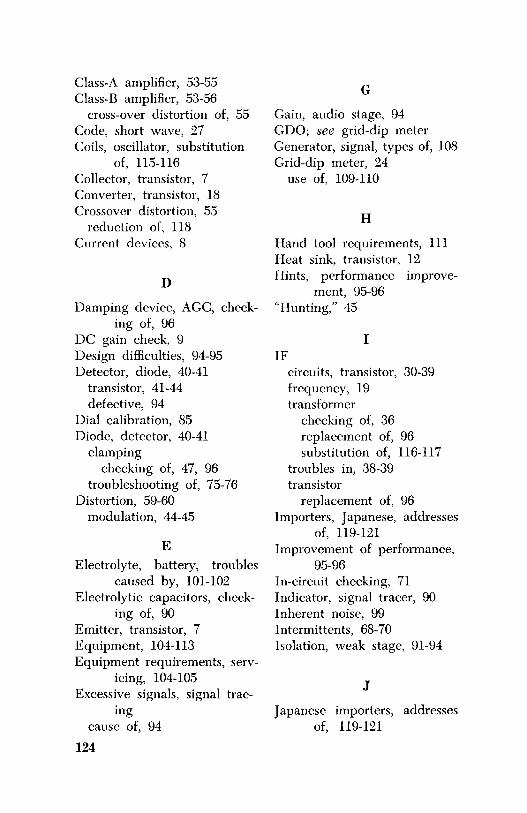
Class-A amplifier, 53-55 Class-B amplifier, 53-56
cross-over distortion of, 55 Code, short wave, 27 Coils, oscillator, substitution
of, 115-116 Collector, transistor, 7 Converter, transistor, 18 Crossover distortion, 55
reduction of, 118 Current devices, 8
D
Damping device, AGC, check-ing of, 96
DC gain check, 9 Design difficulties, 94-95 Detector, diode, 40-41
transistor, 41-44 defective, 94
Dial calibration, 85 Diode, detector, 40-41
clamping checking of, 47, 96
troubleshooting of, 75-76 Distortion, 59-60
modulation, 44-45
E Electrolyte, battery, troubles
caused by, 101-102 Electrolytic capacitors, check-
ing of, 90 Emitter, transistor, 7 Equipment, 104-113 Equipment requirements, serv-
icing, 104-105 Excessive signals, signal trac
ing cause of, 94
124
G
Gain, audio stage, 94 GDO; see grid-dip meter Generator, signal, types of, 108 Grid-dip meter, 24
use of, 109-110
H
Hand tool requirements, 111 Heat sink, transistor, 12 Hints, performance improve
ment, 95-96 "Hunting," 45
I IF
circuits, transistor, 30-39 frequency, 19 transformer
checking of, 36 replacement of, 96 substitution of, 116-117
troubles in, 38-39 transistor
replacement of, 96 Importers, Japanese, addresses
of, 119-121 Improvement of performance,
95-96 In-circuit checking, 71 Indicator, signal tracer, 90 Inherent noise, 99 Intermittents, 68-70 Isolation, weak stage, 91-94
J
Japanese importers, addresses of, 119-121

L
Leaky capacitor, 26, 32 trimmer, 26
Loopstick antenna, 27 open or shorted, 29 substitution of, 114-115
Low impedance devices, 8 Low radio current, 64
M
Meter, grid-dip, 109-110 volt-ohm, 110
Mixer-oscillator, circuits, 19-29 function of, 19 biasing of, 19
Mixer transistor, replacement of, 96
Modified autodyne, 20 Modulation distortion, 44-45 Motorboating, 35
cause of, 99
N
Neutralization, 33-35 Noise, causes of, 97-99
generator, 108 inherent, 99
No-output transformer stage, 56-57
NPN transistor, 7-8, 14-18
0
Ohmmeter check of transistor, 9-11
Open capacitor, 26 Open printed circuits, 102-103 Oscillations, causes of, 99
Oscillator, transistor, 18, 23 checking of, 109-110 coils
substitution of, 115-116 dead, 25-26 feedback of, 21 grid dip, 24, 27
Oscilloscope, use as signal tracer, 107-108
Output meter, 87
p
Parts, stocking of, 112-113 procurement of, 114-118
Performance improvement, 95-96
Pitfalls of tracking, 85-86 PNP transistor, 7-8, 14-18 Power supply, auxiliary, 104-
105 Preamplifier
tape recorder, 51 Printed circuits, open, 102-
103 Protection, thermal, 57 -59
R
Razor blade technique, 77-78 Reflex amplifier, 51-52 Remembering polarities, 8 Removal of parts from boards,
79-82 "soda straw" technique, 79-
80 "brush" technique, 80-81
Repairing broken boards, 82 Replacing parts, 81-82
procurement of, 114-118 Resistors, substitution of, 118
125

s Schematics, 111-112 Sealed alignment screws
(slugs), 88 Service
information, 111-112 techniques, 62-70
Short-wave code, 27 Signal
generator as signal source, 106-108 types of, 108
tracers tuned, 23 types of, 106
tracing take-off point, 90-91 weak radio, 90-94
Small-signal transistor, 8 Snap-on battery plugs, 63 Speakers, substitution of, 117 Squealing, 34-35, 99 Stage gain, audio, 94 Substitution
of parts, 114-118 testing of components, 112-
113 Supplies, stocking of, 112-113 Switches, substitution of, 117
T
Tapped-voice-coil circuit, 57 Tester, transistor, 109 Thermal protection, 57-59 Thermistor, 58-59 Tools, 104-113 Tracking, 28, 83-89, 96 Transformer
audio, substitution of, 117
126
Transformer-cont'd IF
replacement of, 96 substitution of, 116-117
Transistor amplification, 8, 9, 11 base, 7 basing of, 13-14 battery polarity, 12, 15 biasing, 9, 11, 18 collector, 7 converter, 18 current, change of, 8
measurements of, 17-18 DC gain, check of, 9 detectors, 41-44 emitter, 7
bypass capacitor, 16 forward resistance of, 9 heat sink, 12 heating of, 12 IF circuits, 30-39, 96 leakage of, 13 mixer-oscillator, 19, 29, 96 neutralizing, 32 NPN, 7-8, 14 ohmmeter measurements of,
9-12, 71-72 oscillator, 18 PNP, 7-8, 14 replacing, 61 reverse resistance of, 9 schematic interpretation of,
14-15 short in, 11 small signal, 8 substitution of, 27-28, 117-
118 testing of, 71-76, 109 voltage change of, 8 zener condition, 13

Troubleshooting, IF, 35-36 audio amplifiers, 59-61 diodes, 75-76 electrolytics, 76-77
Tuned signal tracer, 23 Tuning capacitor, substitution
of, 116
V Voltage readings, transistor, 17
Volt-ohm meter, 110 Volume controls, substitution
of, 117
w Weak radio, checking of, 90 Weak stage
isolation of, 91-94
127