Embed Size (px)
Citation preview
Transient eddy currents for aircraft structure inspection – an introduction. Buckley, Smith, Skramstad September 2003 Page 1
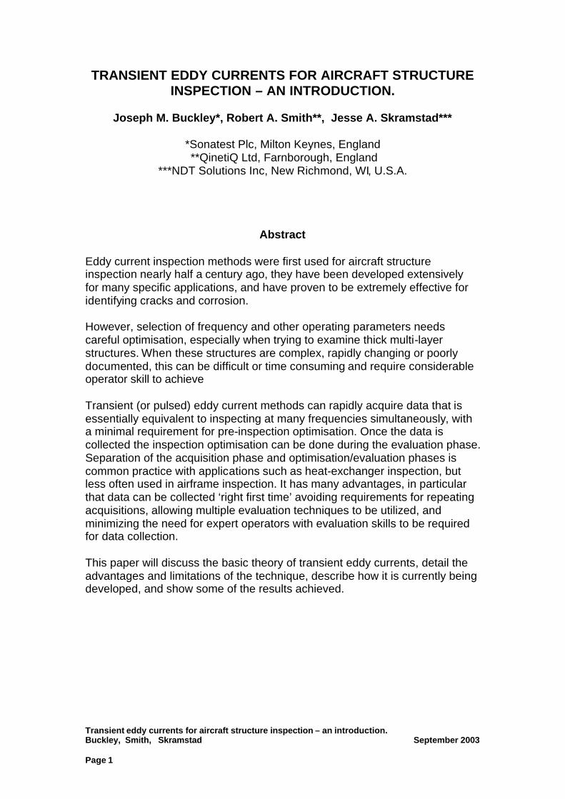
TRANSIENT EDDY CURRENTS FOR AIRCRAFT STRUCTURE INSPECTION – AN INTRODUCTION.
Joseph M. Buckley*, Robert A. Smith**, Jesse A. Skramstad***
*Sonatest Plc, Milton Keynes, England **QinetiQ Ltd, Farnborough, England
***NDT Solutions Inc, New Richmond, WI, U.S.A.
Abstract Eddy current inspection methods were first used for aircraft structure inspection nearly half a century ago, they have been developed extensively for many specific applications, and have proven to be extremely effective for identifying cracks and corrosion. However, selection of frequency and other operating parameters needs careful optimisation, especially when trying to examine thick multi-layer structures. When these structures are complex, rapidly changing or poorly documented, this can be difficult or time consuming and require considerable operator skill to achieve Transient (or pulsed) eddy current methods can rapidly acquire data that is essentially equivalent to inspecting at many frequencies simultaneously, with a minimal requirement for pre-inspection optimisation. Once the data is collected the inspection optimisation can be done during the evaluation phase. Separation of the acquisition phase and optimisation/evaluation phases is common practice with applications such as heat-exchanger inspection, but less often used in airframe inspection. It has many advantages, in particular that data can be collected ‘right first time’ avoiding requirements for repeating acquisitions, allowing multiple evaluation techniques to be utilized, and minimizing the need for expert operators with evaluation skills to be required for data collection. This paper will discuss the basic theory of transient eddy currents, detail the advantages and limitations of the technique, describe how it is currently being developed, and show some of the results achieved.
Transient eddy currents for aircraft structure inspection – an introduction. Buckley, Smith, Skramstad September 2003 Page 2
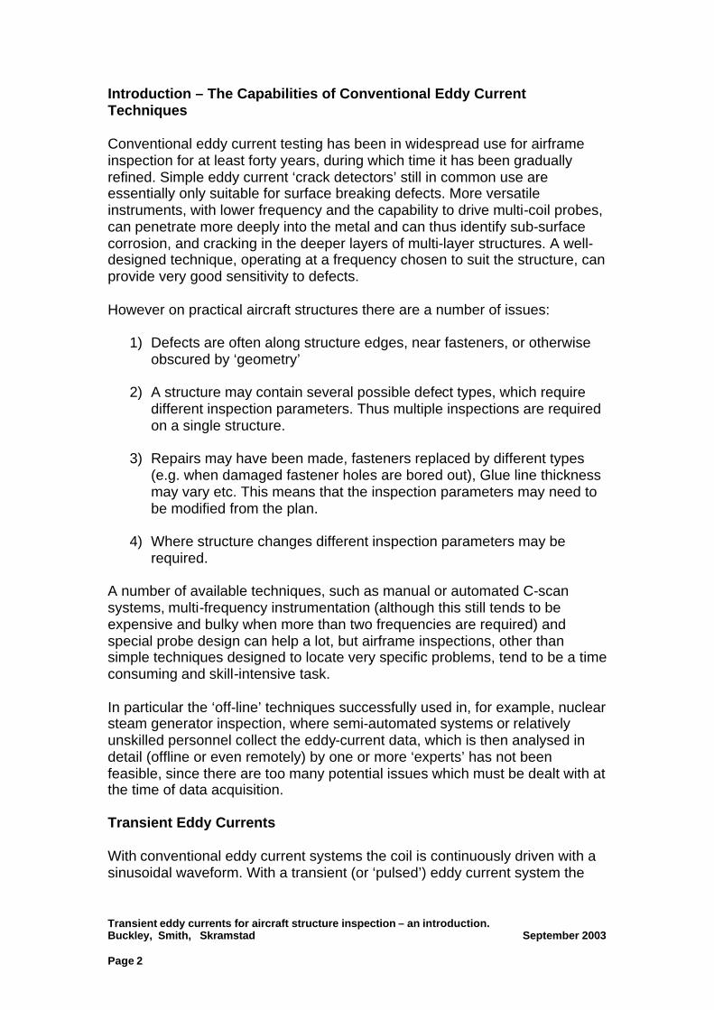
Introduction – The Capabilities of Conventional Eddy Current Techniques Conventional eddy current testing has been in widespread use for airframe inspection for at least forty years, during which time it has been gradually refined. Simple eddy current ‘crack detectors’ still in common use are essentially only suitable for surface breaking defects. More versatile instruments, with lower frequency and the capability to drive multi-coil probes, can penetrate more deeply into the metal and can thus identify sub-surface corrosion, and cracking in the deeper layers of multi-layer structures. A well-designed technique, operating at a frequency chosen to suit the structure, can provide very good sensitivity to defects. However on practical aircraft structures there are a number of issues:
1) Defects are often along structure edges, near fasteners, or otherwise obscured by ‘geometry’
2) A structure may contain several possible defect types, which require different inspection parameters. Thus multiple inspections are required on a single structure.
3) Repairs may have been made, fasteners replaced by different types (e.g. when damaged fastener holes are bored out), Glue line thickness may vary etc. This means that the inspection parameters may need to be modified from the plan.
4) Where structure changes different inspection parameters may be required.
A number of available techniques, such as manual or automated C-scan systems, multi-frequency instrumentation (although this still tends to be expensive and bulky when more than two frequencies are required) and special probe design can help a lot, but airframe inspections, other than simple techniques designed to locate very specific problems, tend to be a time consuming and skill-intensive task. In particular the ‘off-line’ techniques successfully used in, for example, nuclear steam generator inspection, where semi-automated systems or relatively unskilled personnel collect the eddy-current data, which is then analysed in detail (offline or even remotely) by one or more ‘experts’ has not been feasible, since there are too many potential issues which must be dealt with at the time of data acquisition. Transient Eddy Currents With conventional eddy current systems the coil is continuously driven with a sinusoidal waveform. With a transient (or ‘pulsed’) eddy current system the
Transient eddy currents for aircraft structure inspection – an introduction. Buckley, Smith, Skramstad September 2003 Page 3
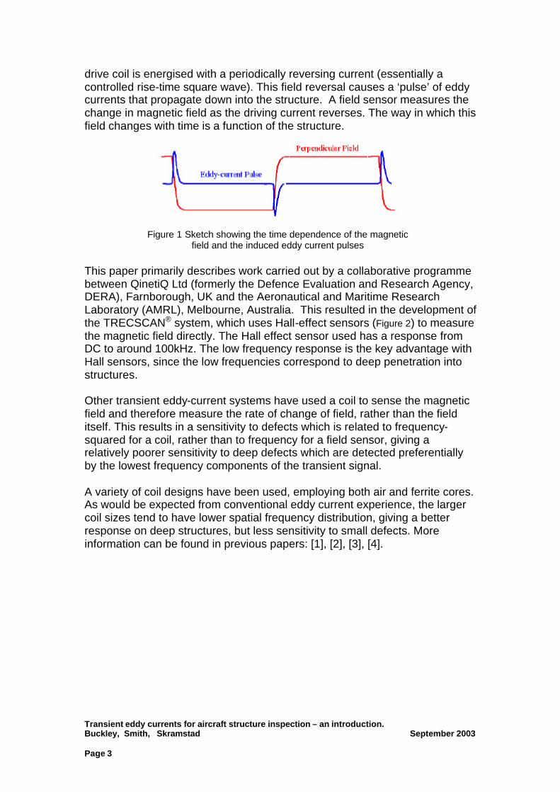
drive coil is energised with a periodically reversing current (essentially a controlled rise-time square wave). This field reversal causes a ‘pulse’ of eddy currents that propagate down into the structure. A field sensor measures the change in magnetic field as the driving current reverses. The way in which this field changes with time is a function of the structure.
Figure 1 Sketch showing the time dependence of the magnetic
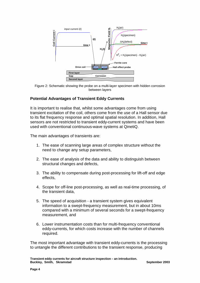
field and the induced eddy current pulses This paper primarily describes work carried out by a collaborative programme between QinetiQ Ltd (formerly the Defence Evaluation and Research Agency, DERA), Farnborough, UK and the Aeronautical and Maritime Research Laboratory (AMRL), Melbourne, Australia. This resulted in the development of the TRECSCAN® system, which uses Hall-effect sensors (Figure 2) to measure the magnetic field directly. The Hall effect sensor used has a response from DC to around 100kHz. The low frequency response is the key advantage with Hall sensors, since the low frequencies correspond to deep penetration into structures. Other transient eddy-current systems have used a coil to sense the magnetic field and therefore measure the rate of change of field, rather than the field itself. This results in a sensitivity to defects which is related to frequency-squared for a coil, rather than to frequency for a field sensor, giving a relatively poorer sensitivity to deep defects which are detected preferentially by the lowest frequency components of the transient signal. A variety of coil designs have been used, employing both air and ferrite cores. As would be expected from conventional eddy current experience, the larger coil sizes tend to have lower spatial frequency distribution, giving a better response on deep structures, but less sensitivity to small defects. More information can be found in previous papers: [1], [2], [3], [4].
Transient eddy currents for aircraft structure inspection – an introduction. Buckley, Smith, Skramstad September 2003 Page 4
time t
Ma
gn
eti
c F
ield
Hz Hz(air)
Hz(specimen)
HRz = Hz(specimen) - Hz(air)
∆Hz(defect)time tC
oil
Cu
rren
t i input current i(t)
Hall effect probe
i(t)
Hz(t)
Drive coil
Ferrite core
First layer
Second layerGap Corrosion
Figure 2: Schematic showing the probe on a multi-layer specimen with hidden corrosion between layers
Potential Advantages of Transient Eddy Currents It is important to realise that, whilst some advantages come from using transient excitation of the coil, others come from the use of a Hall sensor due to its flat frequency response and optimal spatial resolution. In addition, Hall sensors are not restricted to transient eddy-current systems and have been used with conventional continuous-wave systems at QinetiQ. The main advantages of transients are:
1. The ease of scanning large areas of complex structure without the need to change any setup parameters,
2. The ease of analysis of the data and ability to distinguish between structural changes and defects,
3. The ability to compensate during post-processing for lift-off and edge effects,
4. Scope for off-line post-processing, as well as real-time processing, of the transient data,
5. The speed of acquisition - a transient system gives equivalent information to a swept-frequency measurement, but in about 10ms compared with a minimum of several seconds for a swept-frequency measurement, and
6. Lower instrumentation costs than for multi-frequency conventional eddy-currents, for which costs increase with the number of channels required.
The most important advantage with transient eddy-currents is the processing to untangle the different contributions to the transient response, producing
Transient eddy currents for aircraft structure inspection – an introduction. Buckley, Smith, Skramstad September 2003 Page 5
unambiguous defect discrimination and quantitative measurements of material thinning. The main disadvantage with transient eddy current systems is inherent in the broadband data collection; for a specific test the signal to noise ratio is inherently lower than with a conventional eddy current system. In addition, like any new method, transient eddy current techniques require training, validation and qualification of procedures; they must show strong advantages to justify this. Implementation of Transient Eddy Current System Practical implementation requires
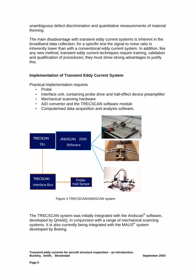
• Probe • Interface unit, containing probe drive and hall-effect device preamplifier • Mechanical scanning hardware • A/D converter and the TRECSCAN software module • Computerised data acquisition and analysis software.
Figure 3 TRECSCAN/ANDSCAN system
The TRECSCAN system was initially integrated with the Andscan® software, developed by QinetiQ, in conjunction with a range of mechanical scanning systems. It is also currently being integrated with the MAUS® system developed by Boeing.
ANDSCAN 2000
Software
Probe: Hall Sensor
TRECSCAN
Interface Box
TRECSCAN
DLL
Phoenix ISL Ltd
Transient eddy currents for aircraft structure inspection – an introduction. Buckley, Smith, Skramstad September 2003 Page 6
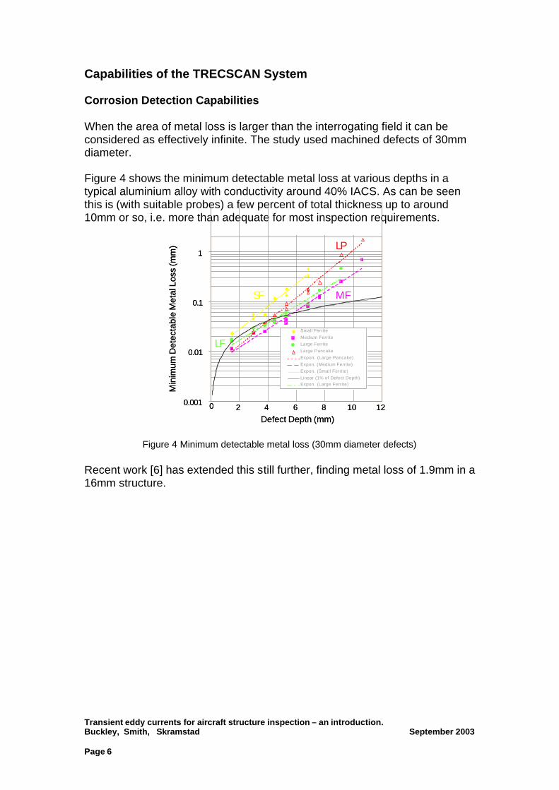
Capabilities of the TRECSCAN System Corrosion Detection Capabilities When the area of metal loss is larger than the interrogating field it can be considered as effectively infinite. The study used machined defects of 30mm diameter. Figure 4 shows the minimum detectable metal loss at various depths in a typical aluminium alloy with conductivity around 40% IACS. As can be seen this is (with suitable probes) a few percent of total thickness up to around 10mm or so, i.e. more than adequate for most inspection requirements.
Small Ferrite
Medium Ferrite
Large Ferrite
Large Pancake
Expon. (Large Pancake)
Expon. (Medium Ferrite)
Expon. (Small Ferrite)
Linear (1% of Defect Depth)Expon. (Large Ferrite)
Min
imum
Det
ecta
ble
Met
al L
oss
(mm
)
0.001
0.01
0.1
1
Min
imum
Det
ecta
ble
Met
al L
oss
(mm
)
0.001
0.01
0.1
1
Defect Depth (mm)
0 2 4 6 8 10 12
Defect Depth (mm)
0 2 4 6 8 10 12
SF
LP
MF
LF
Figure 4 Minimum detectable metal loss (30mm diameter defects)
Recent work [6] has extended this still further, finding metal loss of 1.9mm in a 16mm structure.
Transient eddy currents for aircraft structure inspection – an introduction. Buckley, Smith, Skramstad September 2003 Page 7
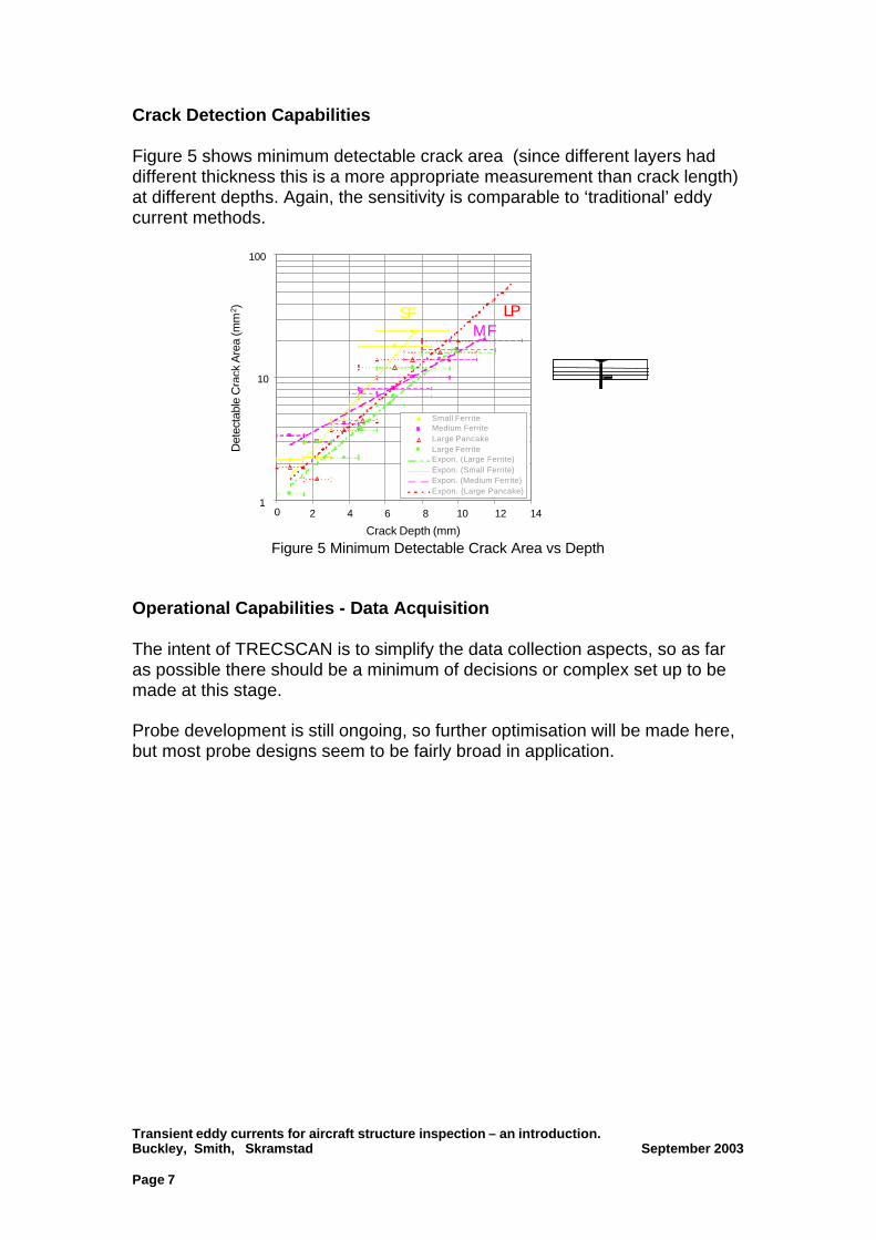
Crack Detection Capabilities Figure 5 shows minimum detectable crack area (since different layers had different thickness this is a more appropriate measurement than crack length) at different depths. Again, the sensitivity is comparable to ‘traditional’ eddy current methods.
0 2 4 6 8 10 12 14
Crack Depth (mm)
Small FerriteMedium FerriteLarge PancakeLarge FerriteExpon. (Large Ferrite)Expon. (Small Ferrite)Expon. (Medium Ferrite)Expon. (Large Pancake)
Crack Depth (mm)
0 2 4 6 8 10 12 14
Crack Depth (mm)
0 2 4 6 8 10 12 14
Det
ecta
ble
Cra
ck A
rea
(mm
2 )
10
100
1
Det
ecta
ble
Cra
ck A
rea
(mm
2 )
10
100
1
LPSFMF
Figure 5 Minimum Detectable Crack Area vs Depth
Operational Capabilities - Data Acquisition The intent of TRECSCAN is to simplify the data collection aspects, so as far as possible there should be a minimum of decisions or complex set up to be made at this stage. Probe development is still ongoing, so further optimisation will be made here, but most probe designs seem to be fairly broad in application.
Transient eddy currents for aircraft structure inspection – an introduction. Buckley, Smith, Skramstad September 2003 Page 8
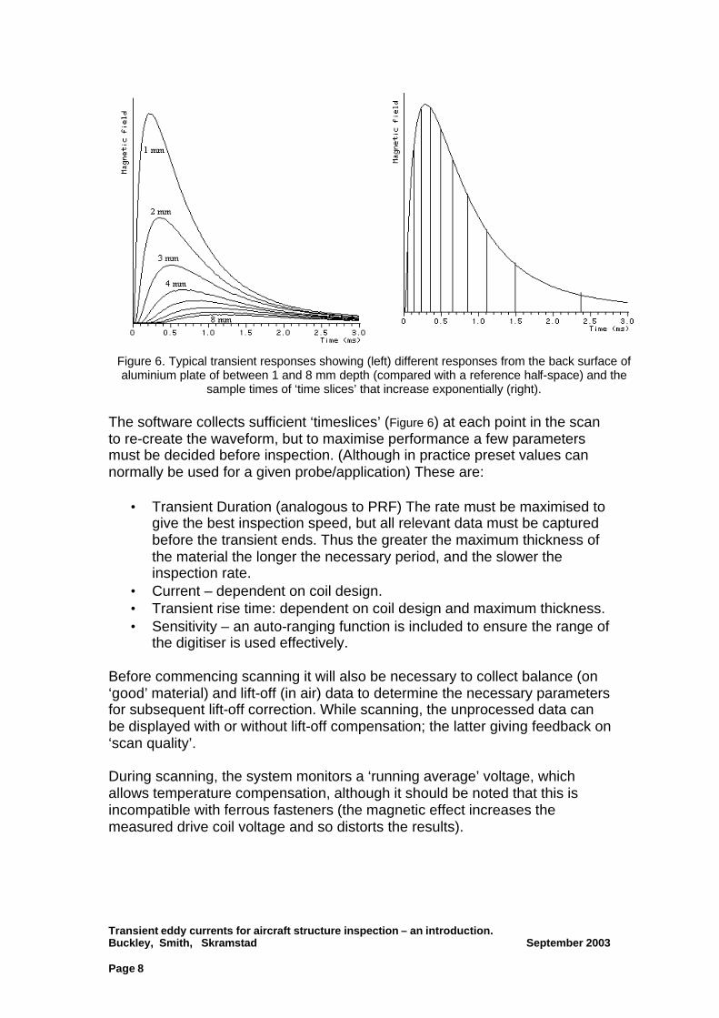
Figure 6. Typical transient responses showing (left) different responses from the back surface of aluminium plate of between 1 and 8 mm depth (compared with a reference half-space) and the
sample times of ‘time slices’ that increase exponentially (right). The software collects sufficient ‘timeslices’ (Figure 6) at each point in the scan to re-create the waveform, but to maximise performance a few parameters must be decided before inspection. (Although in practice preset values can normally be used for a given probe/application) These are:
• Transient Duration (analogous to PRF) The rate must be maximised to give the best inspection speed, but all relevant data must be captured before the transient ends. Thus the greater the maximum thickness of the material the longer the necessary period, and the slower the inspection rate.
• Current – dependent on coil design. • Transient rise time: dependent on coil design and maximum thickness. • Sensitivity – an auto-ranging function is included to ensure the range of
the digitiser is used effectively. Before commencing scanning it will also be necessary to collect balance (on ‘good’ material) and lift-off (in air) data to determine the necessary parameters for subsequent lift-off correction. While scanning, the unprocessed data can be displayed with or without lift-off compensation; the latter giving feedback on ‘scan quality’. During scanning, the system monitors a ‘running average’ voltage, which allows temperature compensation, although it should be noted that this is incompatible with ferrous fasteners (the magnetic effect increases the measured drive coil voltage and so distorts the results).
Transient eddy currents for aircraft structure inspection – an introduction. Buckley, Smith, Skramstad September 2003 Page 9
Operational Capabilities - Data Analysis Once the data has been collected a variety of tools are available to assist with interpretation. Space prohibits detailed discussion of these, but the most significant are:
1. Lift-off compensation as already mentioned, based on ‘in air’ values collected at scan time
2. Edge subtraction, a horizontal or vertical ‘clean line’ on the C-scan can be used as a reference, allowing metal loss or cracks near a thickness change to be detected.
3. ‘Total Thickness’ an algorithm which discriminates between metal loss and spacing changes, allowing corrosion to be accurately quantified.
4. ‘Time to peak’ (after balancing, & compensation) allowing the depth at which a defect is located to be measured
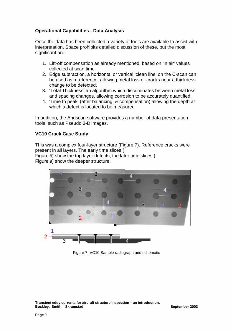
In addition, the Andscan software provides a number of data presentation tools, such as Pseudo 3-D images. VC10 Crack Case Study This was a complex four-layer structure (Figure 7). Reference cracks were present in all layers. The early time slices ( Figure 8) show the top layer defects; the later time slices ( Figure 9) show the deeper structure.
Figure 7: VC10 Sample radiograph and schematic
33
22
11
11
1122
33
33
44
44
44
443322
11
Transient eddy currents for aircraft structure inspection – an introduction. Buckley, Smith, Skramstad September 2003 Page 10
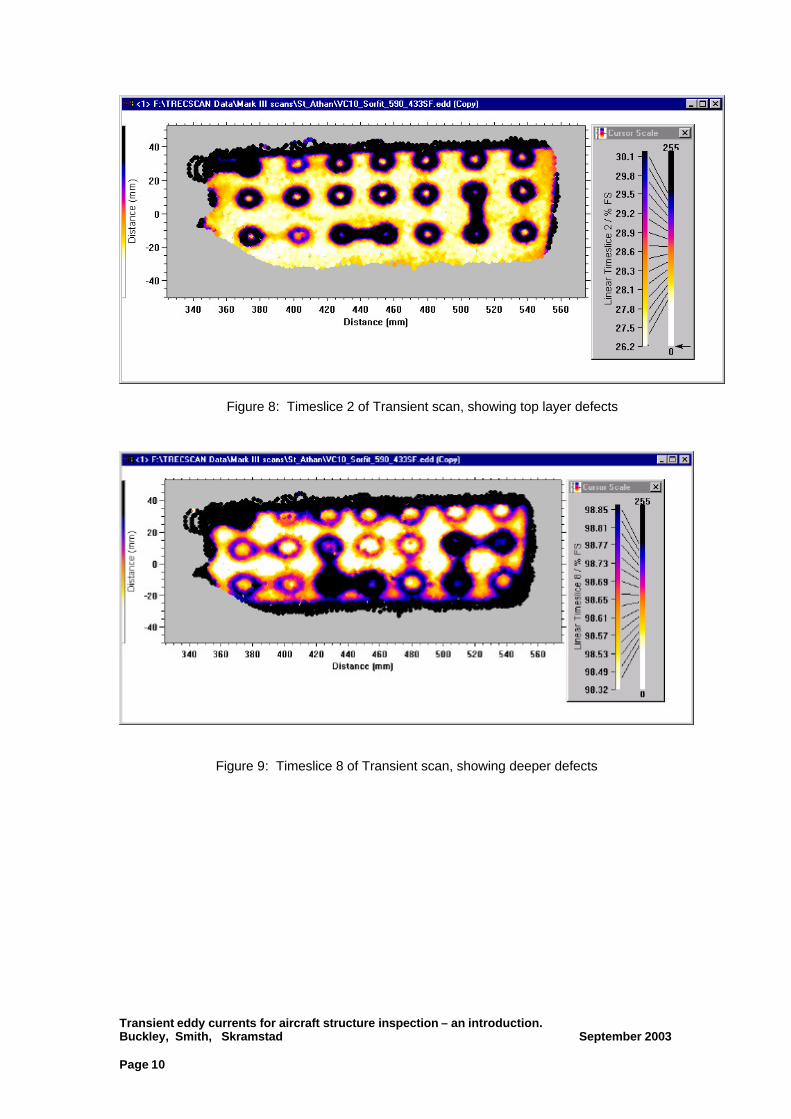
Figure 8: Timeslice 2 of Transient scan, showing top layer defects
Figure 9: Timeslice 8 of Transient scan, showing deeper defects
Transient eddy currents for aircraft structure inspection – an introduction. Buckley, Smith, Skramstad September 2003 Page 11
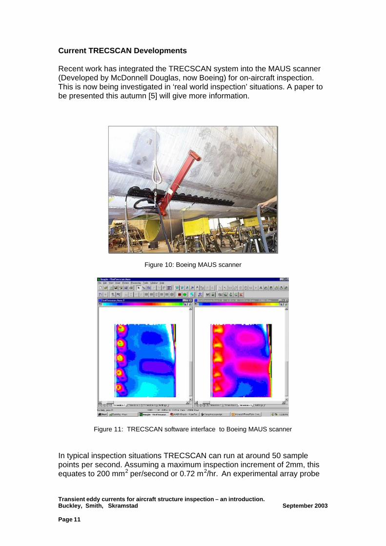
Current TRECSCAN Developments Recent work has integrated the TRECSCAN system into the MAUS scanner (Developed by McDonnell Douglas, now Boeing) for on-aircraft inspection. This is now being investigated in ‘real world inspection’ situations. A paper to be presented this autumn [5] will give more information.
Figure 10: Boeing MAUS scanner
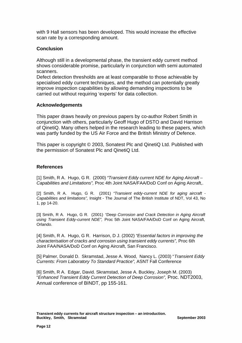
Figure 11: TRECSCAN software interface to Boeing MAUS scanner In typical inspection situations TRECSCAN can run at around 50 sample points per second. Assuming a maximum inspection increment of 2mm, this equates to 200 mm2 per/second or 0.72 m2/hr. An experimental array probe
Transient eddy currents for aircraft structure inspection – an introduction. Buckley, Smith, Skramstad September 2003 Page 12
with 9 Hall sensors has been developed. This would increase the effective scan rate by a corresponding amount. Conclusion Although still in a developmental phase, the transient eddy current method shows considerable promise, particularly in conjunction with semi automated scanners. Defect detection thresholds are at least comparable to those achievable by specialised eddy current techniques, and the method can potentially greatly improve inspection capabilities by allowing demanding inspections to be carried out without requiring ‘experts’ for data collection. Acknowledgements This paper draws heavily on previous papers by co-author Robert Smith in conjunction with others, particularly Geoff Hugo of DSTO and David Harrison of QinetiQ. Many others helped in the research leading to these papers, which was partly funded by the US Air Force and the British Ministry of Defence. This paper is copyright © 2003, Sonatest Plc and QinetiQ Ltd. Published with the permission of Sonatest Plc and QinetiQ Ltd. References [1] Smith, R A. Hugo, G R. (2000) “Transient Eddy current NDE for Aging Aircraft – Capabilities and Limitations”, Proc 4th Joint NASA/FAA/DoD Conf on Aging Aircraft,. [2] Smith, R A. Hugo, G R. (2001) “Transient eddy-current NDE for aging aircraft - Capabilities and limitations”, Insight - The Journal of The British Institute of NDT, Vol 43, No 1, pp 14-20. [3] Smith, R A. Hugo, G R. (2001) “Deep Corrosion and Crack Detection in Aging Aircraft using Transient Eddy-current NDE”, Proc 5th Joint NASA/FAA/DoD Conf on Aging Aircraft, Orlando. [4] Smith, R A. Hugo, G R. Harrison, D J. (2002) “Essential factors in improving the characterisation of cracks and corrosion using transient eddy currents”, Proc 6th Joint FAA/NASA/DoD Conf on Aging Aircraft, San Francisco. [5] Palmer, Donald D. Skramstad, Jesse A. Wood, Nancy L. (2003) “Transient Eddy Currents: From Laboratory To Standard Practice”, ASNT Fall Conference [6] Smith, R A. Edgar, David. Skramstad, Jesse A. Buckley, Joseph M. (2003) “Enhanced Transient Eddy Current Detection of Deep Corrosion”, Proc. NDT2003, Annual conference of BINDT, pp 155-161.