Embed Size (px)
Citation preview

TransGrid’s Submission to the Australian Competition & Consumer
Commission
________________________________________________
Revised Transmission Capital
Investment Program 2004-2009
________________________________________________
Attachment 6D
NSW Main System Outline Plan
November 2004

ATTACHMENT 6D
NSW MAIN SYSTEM OUTLINE PLAN OLP 01
Version 1 – 9th September 2004
Transmission Development File 2004/1680

NSW Main System Outline Plan 9/9/04 Transmission Development - File: 2004/1680
NSW MAIN SYSTEM OUTLINE PLAN
Contents 1. Introduction 2. Reliability Criteria 3. Constraints on Transmission Development 4. Main System Constraints – Summary 5. 500 kV Ring Concept 6. Sydney Area 500 kV Development 7. Supply to the Newcastle Area 8. Central Coast Connections 9. South Coast System 10. South West System 11. Power Station Connections 12. Power Station Development Scenarios 13. A 20 GW System Development 14. Short Circuit Level Issues
Section 6 Attachment 6D 2

NSW Main System Outline Plan 9/9/04 Transmission Development - File: 2004/1680
NSW MAIN SYSTEM OUTLINE PLAN
1. Introduction The NSW main system comprises the 500 kV, 330 kV and 220 kV system that connects the major power stations to the major load centres and the interconnections with other states. This system has been progressively developed over the last 50 years in response to load growth and power station development. This outline plan is aimed at identifying potential main system developments that may be required over the next 15 to 20 years. Reference should be made to the following documents:
• TransGrid Annual Planning Report 2004 • Sydney Area Outline Plan • NEMMCO Statement of Opportunities 2004.
Interconnection developments are addressed in the document “Interconnector Capability and Development Options – Revenue Reset” dated 14/10/2004, File 2002/0757. The Sydney Area Outline Plan covers the 330 kV developments throughout the greater Sydney area. 2. Reliability Standard Broadly the main system is designed to be capable of withstanding the forced outage of a single element at any load level up to peak load, allowing for the range of power flows across the interconnected system which is governed by load levels, generation dispatch and interconnection power flows. Allowance is also made for the necessity to secure the system within 30 minutes of the transmission outage by re-dispatch of generation, in anticipation of subsequent outages. 3. Constraints on Transmission Development The environmental, physical and land-use constraints in NSW are such that it is expected that major new line routes will only be able to be developed once maximum use has been made of existing easements. Any increased capacity would need to be achieved by rebuilding existing lines to a higher capacity when needed. However there are two major constraints on this strategy: (i) To remove an existing line from service while the reconstruction is in progress may
significantly deplete the capability of the network to the extent that in many instances this proposal is impractical.
(ii) Over the past 20 to 30 years since major lines were constructed urban development
has spread to an extent that reconstruction of an existing line, even without needing to increase the existing easement width, is expected to meet with significant community opposition.
Section 6 Attachment 6D 3

NSW Main System Outline Plan 9/9/04 Transmission Development - File: 2004/1680
4. Main System Constraints – Summary
The New South Wales high voltage network was designed to transfer power from the coalfields power stations located in the Hunter Valley, Central Coast and Lithgow areas to the major load centres. Also, the network was designed to transmit the NSW/ACT share of Snowy generation towards Canberra and Sydney. The development of the NEM and interconnection with Queensland will increasingly impose a wider range of loading conditions on the network than was planned.
Some significant network augmentations may be required over the next decade to ensure that intra-regional constraints do not markedly limit the economic operation of the NEM nor adversely affect reliability of supply to NSW load centres.
To assess the potential impact on the New South Wales transmission network of possible future load and generation developments within the NEM, TransGrid has considered a number of load/generation scenarios. Where the timing or extent of constraints is materially affected by NEM load/generation developments, this is indicated in the following sections.
Sydney is surrounded by some major national parks to the north, south and west. Even 20 years ago, when the route of the existing Eraring-Kemps Creek 500 kV line was being secured, it was recognised that the likelihood of securing any further new easements for major transmission lines into Sydney would be remote. Consequently any additional transmission capacity to Sydney and indeed in other congested parts of NSW should focus on re-building existing lines to higher capacity.
The removal from service of a line while it is being rebuilt would be expected to place severe constraints on that part of the network. In general it is not cost effective or practicable to expect a line to be rebuilt at intervals of less than 20 years or so. Consequently the optimum capacity for a new line needs considerable judgement and consideration of practicable alternatives. This process increases the complexity of the already difficult process of assessing optimum transmission works that need to be undertaken to ensure future system capacity is prudently developed in the most cost effective manner.
The NSW main network is interconnected with the Victorian network via the Snowy area, Jindera and Buronga and NSW is also interconnected with the Queensland network. The NSW network is thus an integral part of the interconnected south eastern Australian system. Its adequacy and performance is heavily influenced by the power flows between the state systems.
Figure 7.1 on page 82 of the APR 2004 shows in stylised form the main connections between the NSW generation and load centres with indicative loads in each area as at present. Each connecting link is made up of a number of 330 kV and 500 kV lines. The power flow between the centres is a function of load, generation dispatch and interconnector flows.
Section 6 Attachment 6D 4

NSW Main System Outline Plan 9/9/04 Transmission Development - File: 2004/1680
The overall capabilities of the various sections of the main NSW network are as follows:
Liddell to the North and Far North Coast The 330 kV transmission network north of Liddell supplies virtually all of the northern section of the State. There is very little local generation and there is limited capacity available to transfer loads to Newcastle via the 132 kV system south of Port Macquarie.
This northern network also supports export or import over Directlink (refer below) and the main interconnection to Queensland (QNI).
Two 330 kV single circuit lines extend from Liddell to Armidale via Tamworth and Muswellbrook. The transmission system has limited capacity to supply the area load plus interconnecting flows when any one of the 330 kV lines is unavailable for service. Generator dispatch may need to be rescheduled in the event of a critical line being opened.
The allowable interconnecting flow northward will also diminish as the area load grows. The transmission system capability may be improved in the short term through the installation of some reactive power support plant. There is also potential for a limited degree of line uprating. To secure the long-term supply to the northern area of the state, additional transmission line capacity will be required north of the Liddell/Newcastle area.
Beyond Armidale, transmission to the far northeast of NSW comprises one 330 kV line to Lismore 330/132 kV Substation and an interconnected 132 kV network that supplies substations in the far north eastern area of the state at Coffs Harbour, Koolkhan and Lismore. This area is experiencing a high population growth and a significant increase in demand for electricity.
Directlink forms a high voltage direct current merchant interconnection between the NSW and Queensland systems and can control its power flows according to prevailing market conditions. When Directlink exports to Queensland it imposes a significant additional load on the northern NSW network. Line upratings and the installation of Special Protection Schemes have been necessary to enable Directlink to transfer power to its design capability with all network elements in service.
Additional support to the area will be required to supply the growing load.
The operation of Redbank generation off-loads the Muswellbrook transformers. Whilst the generation continues there is no immediate requirement to reinforce the transformer capacity or lines between Liddell and Muswellbrook / Tamworth due to load reasons alone.
Hunter Valley to the Western Area, Central Coast and Sydney The Hunter Valley is connected to the western area by a double circuit 500 kV line that presently operates at 330 kV. A double circuit 330 kV line connects the Hunter Valley to Sydney and two single circuit 330 kV lines connect to the Newcastle area.
The power flow from the Hunter Valley to the west, Sydney and Newcastle areas is governed by the following factors:
• The level of generation in the Hunter Valley;
• The NSW import/export over QNI;
• The generation in the Central Coast;
• The load in NSW north of the Hunter Valley and on the far north coast; and
• The load level in the Newcastle area which comprises the Newcastle metropolitan area load, the aluminium smelter loads and the load in the southern parts of the mid north coast of NSW supplied from Newcastle.
Section 6 Attachment 6D 5

NSW Main System Outline Plan 9/9/04 Transmission Development - File: 2004/1680
With power transfer over the Queensland – NSW Interconnection (QNI) and Directlink and with operation of Redbank Power Station the existing transmission capability of this system is heavily utilised. The system cannot accommodate any significant additional generation in the Hunter Valley or further north, without reinforcement.
The transmission capability is governed by line thermal ratings and reactive power considerations. Any significant generation development would necessitate an upgrading of the network by uprating or reinforcement of transmission lines.
The development of additional relatively small generators in the Hunter or variations of the generation dispatch patterns under NEM operation from patterns that have predominated in the past, can be expected to require additional reactive power support. This would have a relatively short lead time.
Any major load developments in the Newcastle area may require network reinforcement as these will result in increased loading in the circuits from the Hunter Valley to the Newcastle area. The increase in the flows in these lines relative to flows in the other lines south of the Hunter Valley can result in an overall reduction in the capacity south from the Hunter Valley.
Sydney Area The Sydney area is supplied by the following substations that are closely interconnected with the remainder of the main system:
Kemps Ck
West
Hunter Valley
South Coast
South Coast
Ingleburn
Liverpool
Sydney West
Regentville
Vineyard
Haymarket
Beaconsfield
Sydney South
Syd East
Sydney North
Eraring Central Coast
Section 6 Attachment 6D 6

NSW Main System Outline Plan 9/9/04 Transmission Development - File: 2004/1680
• Sydney North 330/132 kV
• Sydney East 330/132 kV
• Sydney West 330/132 kV
• Sydney South 330/132 kV
• Liverpool 330/132 kV
• Vineyard 330/132 kV
• Regentville 330/132 kV
• Beaconsfield West 330/132 kV
• Ingleburn 330/66 kV
• Kemps Creek 500/330 kV
• Haymarket 330/132 kV.
The interconnected 330 kV system in the Sydney area carries the combined load of these substations (about 6000 MW at present). Some limitations will emerge this decade particularly in the southern part of this system that feeds the Liverpool to Sydney South area.
South Coast to Yass / Canberra Area Four 330 kV lines presently extend from Sydney and the South Coast into the South West and Snowy areas. The lines carry the load of the Yass/Canberra area and the NSW south west as well as interconnection power flow with the Snowy region and Victoria.
Power flow in this network is subject to tidal patterns governed by power transfers between the generators in Queensland, NSW, Snowy and Victorian/South Australian regions.
The four lines to the south share load unequally due to their different lengths and terminal points. Under some load and interconnector power transfer conditions this section of the network can reach its rating. This limitation is exacerbated by the growth of the South West area load and potential future increases in power export from NSW and/or Snowy to the Victorian/South Australian region.
NSW to the Snowy Region and Victoria The New South Wales network is presently interconnected with Victoria at 330 kV via two Murray to Dederang lines and the Wagga to Jindera to Wodonga link, and at 220 kV between Buronga and Red Cliffs.
For the purpose of facilitating generation dispatch and interconnector transfers in the NEM, NEMMCO has established a second region (designated Snowy) within the NSW jurisdiction. This includes the Snowy generating and pumping stations. The region extends across the south of the state so that all power transfer between the NSW and Victorian regions takes place through the Snowy region.
Ownership of 330 kV assets within the Snowy region were transferred from Snowy Hydro to TransGrid in mid 2002. Since taking ownership TransGrid has not changed the rating of the 330 kV transmission lines. Constraints can occur within this region due to the thermal rating of these lines. TransGrid is presently reviewing the condition of these lines and associated terminal equipment with the aim to maximise their thermal rating.
The capability to export power from New South Wales to the south, to supply both Victoria and any pumping load in the Snowy area, is determined by transient stability limitations applicable in the event of a fault on a critical 330 kV transmission line in NSW, and by the thermal rating of plant in southern NSW.
Section 6 Attachment 6D 7

NSW Main System Outline Plan 9/9/04 Transmission Development - File: 2004/1680
Extensive load development in the Murray and Murrumbidgee areas may require reinforcement of 330 kV supply to the area, possibly with a second Wagga - Darlington Point 330 kV line or a 330 kV line from Wagga to Finley and/or Moama. Such a line could form part of a new inter-regional link between NSW and Victoria.
System Voltage Control The security of supply to all of NSW is dependent on ensuring that an adequate supply of reactive power is available for network voltage control. This reactive supply must be available in sufficient quantities and with an adequate response time. The reactive supply is intended to control and arrest declining voltages following outages on the system at times of high loading and to limit the potential for over voltages under light loading conditions.
System voltage control is provided by the following facilities:
• Generator automatic excitation systems;
• Synchronous condensers in the Sydney and Snowy areas;
• Shunt switched capacitor banks at most substations;
• Shunt switched reactors at various locations;
• Static Var compensators at key locations; and
• On load tap changing transformers at most substations.
Planning and operation of the system in NSW relies on being able to make use of the present rated reactive capability of generators, which may exceed the NEC mandatory requirements for generators. In general, significant generation or load developments will require additional reactive support to be provided. This is also the case for any significant increase in power flow through the system as a result of increased interconnector flows.
Power Station Developments
Possible power station developments include the re-development of some existing stations and the development of greenfield stations. The developments could apply a range of technologies including open cycle gas turbine, combined cycle gas turbine, co-generation, coal-based and renewable sources.
Re-development of existing stations may involve additional output from the site and hence there may be a need for reinforcement of the transmission system in the vicinity of these sites.
The possible greenfield generation developments that would impact on the New South Wales system can be categorised as southern, Sydney area, western and northern (which includes the Hunter Valley). These may include, for example:
Southern:
Oaklands (south west of Wagga), Wagga area, Wollongong/South Coast area
Sydney area:
Botany, Kurnell, Other Co-generation opportunities
Section 6 Attachment 6D 8

NSW Main System Outline Plan 9/9/04 Transmission Development - File: 2004/1680
Western:
Lithgow, Mudgee, Cobar areas
Northern:
Hunter Valley area
Narrabri - Gunnedah area
Sugar mill generation in the far north
In addition, there is potential for large scale wind generation in a number of areas of NSW
The transmission systems that may be required for these categories are dependent on:
• The scale of the generation development;
• Whether it is base load, peaking or seasonal generation;
• Whether the generation is to be firmly connected to the bulk transmission system or whether it is to make use of available capacity in the existing transmission system;
• Loss impacts;
• Whether the power station output will be supplied across existing regional boundaries.
Hence it is not possible to be prescriptive about the extent and nature of the longer term transmission developments. Advantage may be able to be taken of the high capacity ring concept. Alternatively further 330 kV or lower voltage line development may be economic.
Some options are as follows:
Sydney Area
New generation is likely to be embedded in the Distributor systems and hence the major impact on TransGrid's system tends to be increased fault duty at existing substations.
Southern Generation
The Marulan to Sydney section of the main system could be developed. This may be able to be achieved through reconstructing lines, such as the existing Yass - Sydney West single circuit 330 kV line, or by developing new lines on new routes.
Western Generation
The transmission capability from the area is limited. It is likely that, due to the presence of national parks to the west of Sydney, major line development would need to be restricted to development of the ring from Marulan into Sydney or from the Hunter Valley towards Sydney. The re-development of existing lines could be considered.
Northern Generation
There is no scope for the present transmission system south of the Hunter Valley to accommodate significant amounts of new generation in the Hunter Valley or further north without either major line works or limitations on imports from Queensland. This assumes no further development of major loads in the Newcastle area in the medium term.
Further development of the ring could be achieved by the re-development of existing 330 kV lines although in some areas lines on new routes may be required. TransGrid has maintained possession of some line easements on the central coast that may facilitate such developments. A new 500/330 kV substation may also be required in the Newcastle area, associated with any 500 kV line development. Uprating the Bayswater/Mt Piper/Marulan line to its design level of 500 kV is expected to be required within the next five years.
Section 6 Attachment 6D 9

NSW Main System Outline Plan 9/9/04 Transmission Development - File: 2004/1680
Major Load Developments Mining, mineral processing, smelting and arc furnace loads may be developed at a number of sites throughout New South Wales. Each may require transmission developments.
Further development of the aluminium smelters in the Newcastle area will require local transmission works and possibly more significant line developments.
The development of arc furnace loads, possibly on or near Kooragang Island, may also require large scale transmission works.
Section 6 Attachment 6D 10

NSW Main System Outline Plan 9/9/04 Transmission Development - File: 2004/1680
5. NSW 500 kV Ring Concept Planning of the NSW main transmission system must take into account the potential for the development of major generation sites and major loads. TransGrid aims to develop the transmission system in an environmentally and socially responsible and cost effective manner. Consistent with this objective is the concept of a high capacity ring linking the Sydney, Newcastle and Wollongong load centres with major generating centres located in the Central Coast, Western coalfields and Hunter Valley. The 500 kV ring is shown in conceptual form in the Figure below.
This development would enable future generating plant to be connected both within the existing generating centres as well as at identified sites for future power stations. It would be capable of being extended for interconnection with Victoria and Queensland. It would also avoid a concentration of lines through the Sydney area thus providing diversity of the main transmission paths from north to south in the state.
The Eraring - Kemps Creek 500 kV line was the first segment of the ring constructed. This was completed to connect Eraring Power Station. The second segment completed was the Bayswater - Mt Piper line associated with the development of Bayswater Power Station. The Mt Piper - Marulan line was developed as the third segment to connect Mt Piper Power Station. The segments of the 500 kV ring between Bayswater and Mt Piper and between Mt Piper and Marulan presently operate at 330 kV.
Future segments that may eventually be required include:
• Hunter Valley to Central Coast - this may be precipitated by the development of major loads in the Newcastle area, additional generation in the Hunter Valley or further north, the import of power from Queensland or the development of western NSW power stations;
• Central Coast to Sydney - this may be required for northern power station developments or significant load developments in the Newcastle area or load development in the northern areas of Sydney;
• Marulan to Sydney - this may be required for any major power station development in the west, south coast or south of the state or to facilitate greater import of power from Victoria.
Loss considerations may be one driver in the further development of this system.
The load growth and the pace of development of power stations has diminished since the construction of Mt Piper Power Station and the timing of the development of further segments of the ring cannot be identified with certainty at this time. Nevertheless the segments of the ring that have been put in place provide an effective, secure and low loss transmission system.
The NSW load is growing. There is an increasing need for power transfer from the north of the state to the south of the state and alternatively from the south of the state towards Sydney to supply the NSW loads at times of peak load. There are a number of issues emerging that require reinforcement of the core system between the Hunter valley and Snowy, including:
• Line thermal limitations, particularly between the Hunter Valley and central coast;
• The transient stability performance of the system; and
• The reactive power support requirements of the core system.
In particular the reactive power requirements of the core system are increasing to the extent that the network is approaching its full capability and the installation of shunt capacitor banks alone will not adequately address the system requirements from about 2007/8. It will be necessary to increase the power transfer capability of the network between the Hunter Valley and Snowy by other means. The upgrading of the Bayswater – Mt Piper – Marulan links to 500 kV operation is presently seen as the most likely solution to the network limitations. This
Section 6 Attachment 6D 11

NSW Main System Outline Plan 9/9/04 Transmission Development - File: 2004/1680
upgrade enables the maximum use of existing lines in the system and avoids the need for new line development.
Interconnection
Generation
Interconnection
Snowy
330 kV Possible
Constructed
Marulan
West
Hunter Valley
CentralCoast
Greater Sydney
Major
Section 6 Attachment 6D 12

NSW Main System Outline Plan 9/9/04 Transmission Development - File: 2004/1680
6. 500 kV Developments in the Sydney Area The Sydney area load growth may require the development of the 500 kV system within the Sydney area. Development of northern generation sources favours reconstruction of lines from the central coast to Sydney. A number of alternative network options are available but the most likely would be to rebuild the Vales Point – Sydney North No. 22 line to a double circuit 500kV line. Extension of the 500 kV system to Kemps Creek via No. 20 or No. 14 line may be feasible. Generation in the south favours reconstruction of the Yass – Sydney West line from Marulan. Redevelopment of a single 330 kV line to double circuit 500 kV may improve the supply capability by the order of 3,000 – 4,000 MW. Sharing of power flow would become an issue and modern power flow control equipment may be required. This plant comes at a high cost and land space would be required. The issues arising from environmental considerations, community concerns, physical construction constraints and substation development associated with line development would require careful management. The figures below show a number of options for 500 kV development. Assessment of these options requires a review of the physical feasibility, particularly with respect to line easements. The existing Sydney area 500 kV and 330 kV system is shown below.
Section 6 Attachment 6D 13

NSW Main System Outline Plan 9/9/04 Transmission Development - File: 2004/1680
Section 6 Attachment 6D 14
Catherine Field
Hunter Valley
Regentville
Ingleburn
South Coast Avon
Yass
Sydney South
Beaconsfield
Haymarket
VineyardSydney North
Central Coast
Eraring
Kemps Ck
West
Liverpool
Sydney West
Sydney East

NSW Main System Outline Plan 9/9/04 Transmission Development - File: 2004/1680
The following figure shows the development of Sydney North 500 kV substation and extension of the 500 kV system to Kemps Creek. The development passes via Sydney West and a 500 kV terminal may need to be developed. Consequential 330 kV developments from Kemps Ck are not shown.
Catherine Field
Hunter Valley
Regentville
Ingleburn
Avon
Yass
Sydney S
Ha
VineyardSydney North
Central Coast
Eraring
Kemps Ck
West
Liverpool
Section 6 A15
Sydney East
ymarket
Sydney Westouth
Beaconsfield
South Coast
ttachment 6D

NSW Main System Outline Plan 9/9/04 Transmission Development - File: 2004/1680
The figure below shows 500 kV development from the south, predominantly along the route of the Yass – Sydney West line with termination at Kemps Creek.
Catherine Field
Hunter Valley
Regentville
Ingleburn
South Coast Avon
Yass
Sydney South
Beaconsfield
Haymarket
VineyardSydney North
Central Coast
Eraring
Kemps Ck
West
Liverpool
Sydney West
Sydney East
Section 6 Attachment 6D 16

NSW Main System Outline Plan 9/9/04 Transmission Development - File: 2004/1680
The 500 kV line may also be able to be extended on to Sydney West. The Eraring – Kemps Ck 50 kV line and the Yass – Sydney West 330 kV line cross in the Luddenham area. There is potential to bus the crossing lines at that point to avoid what would otherwise be a difficult line crossing but more importantly from a network capability point of view to effectively close the 500 kV ring in Sydney.
Catherine Field
Hunter Valley
Regentville
Ingleburn
Avon
Yass
Sydney S
Ha
VineyardSydney North
Central Coast
Eraring
Kemps Ck
West
Liverpool
Section 6 A17
Sydney East
ymarket
Sydney Westouth
Beaconsfield
South Coast
ttachment 6D

NSW Main System Outline Plan 9/9/04 Transmission Development - File: 2004/1680
It is possible that it will not be feasible to gain access to Kemps Creek from the south and one option is to develop a termination at the crossing of the Yass – Sydney West No. 39 line and the Wallerawang – Sydney South double circuit line near Cobbitty. It may be necessary to upgrade the 330 kV system from that point to Sydney West.
Catherine Field
Hunter Valley
Regentville
Ingleburn
Avon
Yass
Sydney S
Ha
VineyardSydney North
Central Coast
Eraring
Kemps Ck
West
Liverpool
Section 6 Attac18
Sydney East
ymarket
Sydney Westouth
Beaconsfield
South Coast
hment 6D

NSW Main System Outline Plan 9/9/04 Transmission Development - File: 2004/1680
There are also potential options for reinforcing areas of the Sydney system from the existing 500 kV line, minimising 330 kV line development. The figure below shows a 500 kV substation supporting the load development in north west Sydney. The extent that the 500 kV system would need to be continued beyond Kemps Ck depends on future generation development. The north west site may also enable support of the 330 kV system in the Sydney North area.
Catherine Field
Hunter Valley
Regentville
Ingleburn
Avon
Yass
Sydney S
Ha
VineyardSydney North
Central Coast
Eraring
Kemps Ck
West
Liverpool
Section 6 Attac19
Sydney East
ymarket
Sydney Westouth
Beaconsfield
South Coast
hment 6D

NSW Main System Outline Plan 9/9/04 Transmission Development - File: 2004/1680
7. Supply to the Newcastle Area
Tomago
Hunter Valley
North Coast
Waratah West Newcastle
Central Coast 330 kV
132 kV
330 kV operating at 132 kV
The load in the Newcastle area comprises the metropolitan area load, smelter loads at Kurri Kurri and Tomago and supply to the mid north coast.
Two 330kV lines from the Hunter Valley and three 330kV circuits from the Central Coast power stations supply the area. A double circuit 330kV line connects Newcastle and Tomago substations with one of the circuits presently operating at 132kV. The system following establishment of Waratah West 330/132 kV Substation is shown above.
Waratah West 132kV switching station currently supplies some industrial customers near the Hunter River and also supplies coastal loads north of Newcastle.
To meet increased load requirements at Tomago smelter a third 330kV circuit will soon be connected to Tomago from Newcastle. A 330/132kV transformer is also to be soon established at Waratah West to ensure a firm supply to the substation. This will also provide windows of opportunity for major planned maintenance of the Newcastle 330/132kV transformers and meet the increasing load levels in the Newcastle Region.
The need for further augmentation to the supply in the area is driven by the following factors:
• The need to carry out major planned maintenance of the Newcastle 330/132 kV transformers;
• Development of additional aluminium smelting loads; and
• Development of other significant loads in the Tomago or Kooragang Island area.
Section 6 Attachment 6D 20

NSW Main System Outline Plan 9/9/04 Transmission Development - File: 2004/1680
Any major new industrial developments in the Newcastle area may require substantial local 330kV system developments as well as reinforcement of the 330kV system from the Hunter Valley and/or Central Coast power stations.
A range of demand-side and network augmentations provide options for responding to the maintenance needs at Newcastle, general load growth in the area and possible industrial load increases. These include:
• Development of demand management options;
• Development of local generation;
• 330kV line reconnection in the Central Coast area to improve load sharing on 330 kV lines;
• Construction of local 330kV and 132kV lines to supply new large industrial customers;
• Construction of a double circuit 330 kV line (or 500kV line initially operating at 330kV) to reinforce the main grid to meet any large new industrial loads;
• Construction of a new 330kV switching station west of Newcastle. This would allow lines from the Hunter Valley to be marshalled and could form part of a future 500/330kV or 330/132 kV substation in the Newcastle area;
• Provision of additional 330/132 kV transformer capacity, most probably by installing an additional transformer and a 330 kV busbar at Waratah West; and
• Provision of additional reactive compensation.
Section 6 Attachment 6D 21

NSW Main System Outline Plan 9/9/04 Transmission Development - File: 2004/1680
8. Central Coast Connections
The NSW main system connections between the central coast power stations and Newcastle are shown in the figure below.
Turn in using existing spare line
section
Syd West
26
24
Kemps Ck 500 kV
Newcastle
92
Network Connections between Ne
Section 6 22
93
22
Syd Nt25
Vineyard
wcastle, Eraring a
Eraring 500
Eraring 330
h Tuggerah
Vales Pt
Munmorah
nd Vales Point
Attachment 6D

NSW Main System Outline Plan 9/9/04 Transmission Development - File: 2004/1680
The need for system augmentation in this part of the network arises due to three factors:
• Potential constraints on the operation of the central coast power stations;
• An emerging need to gain greater support of the Newcastle area voltage using the reactive power generation capability of Eraring Power Station.
• The potential to reduce system losses in the case of network augmentations;
The Newcastle – Vales Pt 330 kV line No. 24 is to be turned into Eraring as shown in the figure above. The connections to Vales Pt and Munmorah are also to be rearranged to provide better sharing of line loads. Fault level constraints then require the application of the Munmorah series reactor.
Section 6 Attachment 6D 23

NSW Main System Outline Plan 9/9/04 Transmission Development - File: 2004/1680
9. South Coast System
Kangaroo Valley Yass/Canberra
Snowy
Western Generators
Sydney
Wollongong
Constraint
Marulan
Four 330 kV lines presently extend from Sydney and the south coast to the south west of NSW and the Snowy region. The capability of this system immediately south of Marulan to transfer power from Snowy to the north or from the Sydney area into the southwest area of NSW is limited by line thermal ratings.
Power transfer north from Snowy is dictated by the dispatch of Snowy Hydro generation and Victorian export into NSW. Power transfer to the south is governed by load levels in the southwest area, the operation of the Snowy generation and overall power transfer from NSW to Victoria.
The transmission system is expected to need support to supply the growing southwest area load with power flow in a southerly direction. Reinforcement by transmission development would also increase the capability for the export of power from NSW to Victoria and possibly from Victoria to NSW.
TransGrid has undertaken uprating of the existing lines between Marulan and Yass in recent times. Further upgrading is planned in the future as required to minimise system limitations due to ongoing load growth.
There are a number of options for further relieving the supply constraints, including:
Section 6 Attachment 6D 24

NSW Main System Outline Plan 9/9/04 Transmission Development - File: 2004/1680
• Diversion of the existing Sydney West to Yass 330 kV line into Marulan;
• Establishing a switching station at the intersection of the Mt Piper – Marulan lines and the Yass – Sydney West line at a site nominally referred to as Bannaby;
• Installation of power flow control equipment on the 330 kV lines; and
• Construction of new transmission lines between Marulan and Yass, which may include 500 kV line development options.
At this stage one indicative network option that will achieve a low level upgrade of the system capability is either the establishment of a new substation at Bannaby or the diversion of the Sydney West - Yass 330 kV line into Marulan.
The Bannaby site may also be utilised to connect potential wind farms in the southern tablelands area.
Section 6 Attachment 6D 25

NSW Main System Outline Plan 9/9/04 Transmission Development - File: 2004/1680
Kangaroo Valley Yass/Canberra
Snowy
Western Generators
Sydney
Wollongong
Constraint Marulan
Marulan connects to the south coast system via two 330 kV lines. The south coast is further supported by a 330 kV line from Canberra via Kangaroo Valley and two 330 kV lines from Sydney.
When NSW is importing heavily from Snowy and Victoria there can be relatively high power flows between Marulan and the south coast substations. The flow is exacerbated by high generation levels in the western power stations.
A constraint emerges on the lines between Marulan and the south coast due to the limited rating of the lines.
TransGrid has considered a number of options for further relieving the supply constraints, including:
• Diversion of the existing Sydney West to Yass 330 kV line into Marulan;
• Establishing a substation at Bannaby;
• Installation of power flow control equipment on the 330 kV lines;
• Development of new 330 kV lines; and
• Uprating of the Marulan – Avon and Marulan – Dapto 330 kV lines.
At this stage line uprating may provide an adequate solution in combination with the diversion of the Sydney West – Yass line to Marulan or establishment of a substation at Bannaby.
Section 6 Attachment 6D 26

NSW Main System Outline Plan 9/9/04 Transmission Development - File: 2004/1680
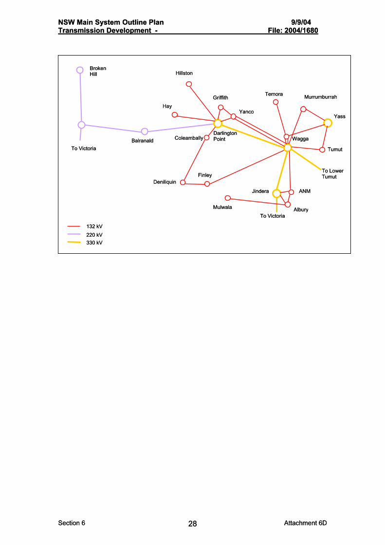
10. South West System The south western transmission system, west of Wagga Wagga and Albury, supplies:
A 132kV system supplying Yanco and Griffith; •
•
•
•
•
A 132kV system supplying Coleambally, Deniliquin and Finley;
A 132kV system supplying Mulwala;
A 220kV system supplying Balranald, Broken Hill and Redcliffs; and
Interconnections to Victoria via Redcliffs (220kV) and Wodonga (330kV).
The loading in the 132 kV systems is approaching the capacity of the network.
Darlington Point 330/220/132 kV substation is the primary supply point for the 132 kV system in the south west of the state and for the 220 kV system that supplies Broken Hill and interconnects with the Victorian and South Australian systems at Red Cliffs.
An outage of the Wagga to Darlington Point 330 kV line may lead to voltage stability problems on the south west 132 kV system. Special Protection Schemes have been applied to extend the capability of this system.
A number of factors may further exacerbate the adverse impacts of an outage of the Wagga to Darlington Point 330 kV line including:
• Increasing loads on the 132 kV system supplied from Darlington Point;
• Increasing power flows between New South Wales and Victoria on existing lines;
• The operation of MurrayLink connection between Victoria (Red Cliffs) and South Australia (Berri) drawing load through the Darlington Point substation; and
• Possible further interconnection to Victoria from Darlington Point.
The options available to reinforce this system include a second Wagga – Darlington Pt 330 kV line and development of interconnection with Victoria, supporting loads along the Murray River in both NSW and Victoria.
Continuing growth in the loads in the area requires the use of under voltage load shedidng and capacitor support.
Section 6 Attachment 6D 27
NSW Main System Outline Plan 9/9/04 Transmission Development - File: 2004/1680
Broken Hill Broken Hill HillstonHillston
Temora Temora MurrumburrahMurrumburrahGriffith Griffith HayHay
Yanco Yanco YassYass
Darlington Point Darlington Point Coleambally Coleambally Wagga Wagga Balranald Balranald
To Victoria To Victoria TumutTumut
To Lower Tumut To Lower Tumut FinleyFinley
DeniliquinDeniliquin
ANM ANM JinderaJindera
MulwalaMulwala Albury Albury To Victoria To Victoria
132 kV 132 kV 220 kV 220 kV 330 kV 330 kV
NSW Main System Outline Plan 9/9/04 Transmission Development - File: 2004/1680
Section 6 Attachment 6D 28
Section 6 Attachment 6D 28

NSW Main System Outline Plan 9/9/04 Transmission Development - File: 2004/1680
The 330 kV and 220 kV system and underlying132kV system in the Yass – Wagga area is shown in stylised form in the Figure below. The 132 kV system is shown as simple links operating in parallel with the 330 kV system. Yass and Canberra are connected to the north to the remainder of the NSW system. Dederang is connected to the Victorian 330 kV and 220 kV system. Similarly Red Cliffs is connected to the western Victorian 220 kV network.
132 kV
220 kV 330 kV
220 kV
Victoria
Broken Hill 132 kV
330 kV
Red Cliffs
Darlington Point
Jindera
Wodonga
Dederang
Yass
Canberra
Murray
Upper Tumut
Buronga
Lower Tumut
Wagga
Power from the Snowy Hydro generators that are connected to the switching stations at Murray, Lower
Tumut and Upper Tumut is transmitted to the south west area loads and to the north and south via the 330 kV system. Power flow between NSW and Victoria (in either direction) is superimposed on this loading.
In recent years Victoria has relied on the capability for import from NSW/Snowy regions of a nominal 1,900 MW at times of peak summer load.
At times when Victoria is importing power and the NSW system load is relatively high there will be a relatively high power flow from Murray towards Dederang and from Lower Tumut to Wagga, Jindera and thence to Victoria. Part of the overall Victorian import is also carried west from Wagga to Buronga and thence Red Cliffs.
If all network elements are in service, the 330 kV network is expected to be capable of adequately supplying the loads in the immediate Wagga - Yass area over the next ten years, with only minor upgrading of existing elements and the installation of voltage support plant being required.
However, under conditions of high area load and high Victorian import the following become critical contingencies:
Section 6 Attachment 6D 29

NSW Main System Outline Plan 9/9/04 Transmission Development - File: 2004/1680
i) An outage of the Lower Tumut - Wagga 330 kV line results in a high loading in the Yass 330/132 kV transformers and 132 kV lines from Yass to Wagga. High loadings in the Murray – Dederang lines also occur.
ii) An outage of one of the two Yass 330/132 kV transformers causes a high loading in the remaining transformer.
iii) An outage of the Lower Tumut - Wagga line leads to reactive power deficiencies (low voltages) in the Wagga area.
iv) An outage of a Murray - Dederang line results in a high loading in the Lower Tumut - Wagga line and the remaining Murray – Dederang line.
Continuing growth of NSW loads in this region, coupled with a requirement for power transfer from Snowy to Victoria, will exacerbate the potential overloading of lines and transformers. Unless new generating developments can be made available in Victoria it is expected that the frequency of high power flows through the Wagga area will rise.
The development of a Yass - Wagga 330 kV line would firm up supply to the south west area and support increased power transfer capacity to the Victorian and South Australian regions.
For many years the direct 132 kV line No.990 from Yass to Wagga has been seen as a candidate for reconstruction to 330 kV. The line is considered to require substantial expenditure to maintain and rebuild to a serviceable condition. Careful consideration needs to be given to the type of line developed to fully utilise the capacity of this valuable route to minimise the need for further line developments over this sector.
Planning for a new Yass – Wagga 330 kV line must also take into account possible options for augmenting the interconnection with Victoria involving power flow control equipment and new transmission line development.
A number of possible projects have been considered. Some of these schemes involve alternating current and HVDC links from southwest NSW to Victoria.
New interconnecting line options would aim to provide a high power capability connection from south west NSW to near Melbourne. Virtually all of the options involve the development of a transmission line that passes through the Wagga area. In most of the options it may be possible to integrate the development of the interconnecting line with the reinforcement of the supply to the Wagga area.
There is a range of possible line developments that may meet the short and longer term needs of an interconnection augmentation and a Yass - Wagga connection, including:
• A single circuit 330 kV line;
• A double circuit 330 kV line;
• A double circuit 500 kV line initially operating at 330 kV;
• A hybrid dc/ac line consisting of a bipole HVDC line and a single circuit 330 kV line sharing common towers.
Section 6 Attachment 6D 30

NSW Main System Outline Plan 9/9/04 Transmission Development - File: 2004/1680
11. Power Station Connections The following are indicative developments for the direct connection of potential new major power stations. The extent of connection works will depend on the size of the power station. Deep main system reinforcements would be required for any new power station, such as the developments set out in Section 12.
11.1 Coal-Fired Power Stations
Narrabri / Gunnedah area
Connections to the South Tamworth area, at a new switching station, and to Gungal west of Bayswater are expected to be required.
The developments would be most likely required at 500 kV.
Narrabri provides a potential termination for additional interconnection with Queensland.
Hunter Valley – Foybrook – Mt Arthur area
Direct connection to the Bayswater 500 kV switchyard is expected. Integration with a 500 kV line to the coast is possible.
Ulan / Rylstone area
The power station would be connected to the Bayswater – Mt Piper line
Mt Piper 3-4 The power station would be connected to the 500 kV bus. Oaklands The power station may be integrated with an interconnector with Victoria Extensive transmission development would be required to the Wagga area and towards Sydney. 11.2 Major Gas-Fired Power Stations Major gas-fired power stations may be directly connected to existing power station busbars or substation busbars. At some sites, such as in the Tomerong area, existing lines may be diverted to the switchyard that would be established for the new power station. 11.3 Major Wind Parks Sites are generally to be connected at 330 kV or 132 kV by turning existing lines into the site. In some locations new radial lines may need to be constructed.
Section 6 Attachment 6D 31

NSW Main System Outline Plan 9/9/04 Transmission Development - File: 2004/1680
12. Power Station Development Scenarios The development of the main transmission system is critically dependent on the system load growth, the geographical distribution of generation development and any variations from the present interconnection arrangements with Victoria and Queensland. Environmental considerations and any emerging or new technologies in power transmission will also impact on the future development of the system. This section illustrates possible main transmission developments for a range of load growth and generation development scenarios. Such transmission development encompasses the transmission developments required for the individual power station developments discussed in Section 11. Four basic development scenarios are presented here which cover a range of load growth and generation development scenarios. It must be emphasised that adjustments to these typical transmission developments may be necessary for technical and economic reasons, to accommodate particular plant development programs, specific power station and substation siting and also line routing constraints. The first transmission development scenario indicates possible line and substation requirements for medium load growth met with new power stations at Gunnedah, Foybrook, Ulan / Rylstone, Oaklands and Tallawarra together with 2000 MW of new gas turbines. Some existing power station sites have been considered to have been redeveloped at the stage presented here. The power station distribution is a combination of Hunter Valley, western and southern development with the 2000 MW of gas turbine units predominantly in the south. The second transmission development scenario applies to higher system load growth with power stations additional to the above case at Bylong, Ulan, Mt Piper and Gunnedah. An additional 400 MW of gas turbines is located in the south coast. The power station development is therefore biased towards northern and western coal-fired power station development. A very low road growth situation is represented in the third transmission development scenario. New power stations have been considered developed at Tallawarra, Oaklands and Foybrook together with 800 MW of gas turbines. Munmorah Power Station has been replaced by two 660 MW units. The fourth transmission development scenario represents a high extreme of expected load growth and illustrates the transmission system that may be required for high southern, western and northern generation development.
Section 6 Attachment 6D 32

NSW Main System Outline Plan 9/9/04 Transmission Development - File: 2004/1680
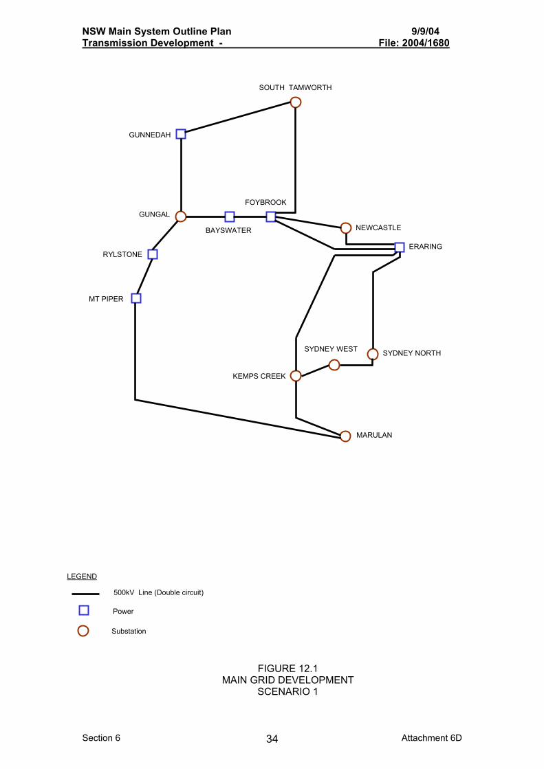
Transmission Development Scenario 1 Power station development Station Units Comments
Liddell
Munmorah
Gunnedah
Foybrook
Rylstone
Oaklands
Tallawarra
Jindera
Central Coast
South Coast
4 x 660 MW
2 x 660 MW
4 x 660 MW
4 x 660 MW
4 x 660 MW
4 x 660 MW
2 x 660 MW
8 x 100 MW
4 x 100 MW
8 x 100 MW
Site extension
Site extension
New site
New site
New site
New site
Site extension
Gas turbines
Gas turbines
Gas turbines The required main transmission 500 kV grid development for this scenario is indicated in Figure 12.1. The 500 kV system is developed to link the Hunter valley and western stations to the major load areas, whilst generation to the south of the State is accommodated at 330 kV. Load growth and transmission loadings require new 500/330 kV substations at Newcastle, Sydney North, Sydney West and Marulan with a 500 kV switching station near Gungal. Although the Gunnedah station is shown here connected at 500 kV it is evident that 330 kV would be an economic alternative providing there was to be no further power station development in the northern area beyond the above four units and no further interconnection development with Queensland. Bannaby provides an alternative site to Marulan for a 500 kV switchyard.
Section 6 Attachment 6D 33
NSW Main System Outline Plan 9/9/04 Transmission Development - File: 2004/1680
H
GUNNEDAH
RYLSTONE
GUNGALFOY
BAYSWATER
KEMPS
MT PIPER
LEGEND
500kV Line (Double circuit)
Substation
FMAIN GR
S
Section 6
SOUTH TAMWORT
BROOK
SYDNEY WEST
CREEK
SYDNEY NORTH
ERARING
NEWCASTLE
MARULAN
Power
IGURE 12.1 ID DEVELOPMENT CENARIO 1
Attachment 6D 34

NSW Main System Outline Plan 9/9/04 Transmission Development - File: 2004/1680
Transmission Development Scenario 2 Power station development Station Units Comments
Liddell
Munmorah
Gunnedah
Foybrook
Rylstone
Ulan
Bylong
Oaklands
Tallawarra
Mt Piper
Wallerawang
Jindera
Central Coast
South Coast
4 x 660 MW
2 x 660 MW
8 x 660 MW
4 x 660 MW
4 x 660 MW
4 x 660 MW
4 x 660 MW
4 x 660 MW
2 x 660 MW
2 x 660 MW
2 x 660 MW
8 x 100 MW
4 x 100 MW
12 x 100 MW
Site extension
Site extension
Assumed at one new site
New site
New site
New site
New site
New site
Site extension
Site extension
Present site
Gas turbines
Gas turbines
Gas turbines
The required 500 kV transmission development for this scenario is shown in Figure 12.2 and is fundamentally similar to that of the first scenario. The additional western and northern stations are connected to the 500 kV network. The additional gas turbine generation in the South Coast requires an additional 330 kV line to be turned into the power station together with additional transmission support, possibly in the form of a double circuit reconstruction of the 330 kV line to Dapto. The higher load, northern and western generation results in generally heavier power flows in the 500 kV network.
Section 6 Attachment 6D 35

NSW Main System Outline Plan 9/9/04 Transmission Development - File: 2004/1680
Section
LEGEND 500kV Line (Double circuit)
SOUTH TAMWORTH
MT PIPER
GUNNEDAH
RYLSTONE
ULAN
GUNGAL
FOYBROOK
BAYSWATER
SYDNEY WEST
KEMPS CREEK
SYDNEY NORTH
ERARING
NEWCASTLE
MARULAN
Power
6 Attachment 6D 36
FIGURE 12.2 MAIN GRID DEVELOPMENT
SCENARIO 2
Substation

NSW Main System Outline Plan 9/9/04 Transmission Development - File: 2004/1680
Transmission Development Scenario 3 Power station development Station Units Comments
Munmorah
Foybrook
Oaklands
Tallawarra
Central Coast
South Coast
2 x 660 MW
4 x 660 MW
4 x 660 MW
2 x 660 MW
4 x 100 MW
4 x 100 MW
Site extension
New site
New site
Site extension
Gas turbines
Gas turbines The required transmission development for this scenario is indicated in Figure 12.3. The 500 kV network is developed to a lesser extent than in the above two cases with some 500 kV lines in service operation at 330 kV. The 500 kV system must be developed between Hunter Valley and the Central Coast, whilst the Marulan to Kemps Creek sections of the ring may possibly be operated at 330 kV. Network loss and reactive conditions may well require operation at 500 kV. Naturally this situation would be vastly different if generation development was predominantly in either the north or south of the State.
Section 6 Attachment 6D 37

NSW Main System Outline Plan 9/9/04 Transmission Development - File: 2004/1680
FOYBROOK
BAYSWATER
KEMPS CREEK
Possible 330kV Operation
NEWCASTLE
MARULAN
ERARING
MT PIPER
LEGEND 500kV Line (Double circuit)
Section
Power
Substation
FIGURE 12.3 MAIN GRID DEVELOPMENT
SCENARIO 3
6 Attachment 6D 38

NSW Main System Outline Plan 9/9/04 Transmission Development - File: 2004/1680
Transmission Development Scenario 4 Power station development Station Units Comments
Liddell
Munmorah
Gunnedah
Foybrook
Rylstone
Oaklands
Ulan
Bylong
Tallawarra
Mt Piper
Wallerawang
Jindera
Central Coast
South Coast
4 x 660 MW
2 x 660 MW
8 x 660 MW
4 x 660 MW
4 x 660 MW
8 x 660 MW
4 x 660 MW
4 x 660 MW
2 x 660 MW
2 x 660 MW
2 x 660 MW
12 x 100 MW
8 x 100 MW
12 x 100 MW
Site extension
Site extension
New site
New site
New site
New site
New site
New site
Site extension
Site extension
Present site
Gas turbines
Gas turbines
Gas turbines The flexibility of the planned 500 kV ring is highlighted by the required transmission development for this scenario, as indicated in Figure 12.4a. One extra 500 kV line between Rylstone and Mt Piper may be required in addition to the “ring” requirements for a moderate load growth development. As previously, load growth and transmission loadings require new 500/330 kV substations at Newcastle, Sydney North, Sydney West and Marulan with a 500 kV switching station near Gungal. The intensive development of the Oaklands area would require 500 kV development south of Marulan.
Section 6 Attachment 6D 39

NSW Main System Outline Plan 9/9/04 Transmission Development - File: 2004/1680
Section 6
CANBEAREA
(1) Indicates single circuit
MAI
LEGEND
Substation
500kV Line (Double circuit)
H
OAKLANDS
(1)
REGENTVILLE
ULAN
(1)
GUNNEDAH
MT PIPER
RYLSTONE
GUNGAL
BAYSWATER
KEMPS
SOUTH TAMWORT
RRA
FOYBROOK
SYDNEY WEST
CREEK
SYDNEY NORTH
ERARING
NEWCASTLE
MARULAN
Power
WAGGA
Attachment 6D 40
FIGURE 12.4(a) N GRID DEVELOPMENT
SCENARIO 4

NSW Main System Outline Plan 9/9/04 Transmission Development - File: 2004/1680
Another option for transmission development for this scenario is shown in Figure 12.4b where a 330 kV line between Wallerawang and Sydney has been reconstructed to 500 kV, in place of the reconstructed Bayswater to Sydney line indicated in Figure 12.4a. SOUTH TAMWORTH
CANBERRA
WAGGA
OAKLANDS
(1)
MINTO
(1)
(1) Indicates single circuit
ULAN
FIGURE 12.4(b) MAIN GRID DEVELOPMENT
SCENARIO 4
LEGEND
Substation
Power
500kV Line (Double circuit)
GUNNEDAH
MT PIPER
RYLSTONE
GUNGAL
FOYBROOK
BAYSWATER
SYDNEY WEST
KEMPS CREEK
SYDNEY NORTH
ERARING
NEWCASTLE
MARULAN
Section 6 Attachment 6D 41
NSW Main System Outline Plan 9/9/04 Transmission Development - File: 2004/1680
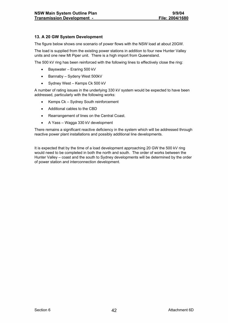
13. A 20 GW System Development The figure below shows one scenario of power flows with the NSW load at about 20GW.
The load is supplied from the existing power stations in addition to four new Hunter Valley units and one new Mt Piper unit. There is a high import from Queensland.
The 500 kV ring has been reinforced with the following lines to effectively close the ring:
• Bayswater – Eraring 500 kV
• Bannaby – Sydeny West 500kV
• Sydney West – Kemps Ck 500 kV
A number of rating issues in the underlying 330 kV system would be expected to have been addressed, particularly with the following works:
• Kemps Ck – Sydney South reinforcement
• Additional cables to the CBD
• Rearrangement of lines on the Central Coast.
• A Yass – Wagga 330 kV development
There remains a significant reactive deficiency in the system which will be addressed through reactive power plant installations and possibly additional line developments.
It is expected that by the time of a load development approaching 20 GW the 500 kV ring would need to be completed in both the north and south. The order of works between the Hunter Valley – coast and the south to Sydney developments will be determined by the order of power station and interconnection development.
Section 6 Attachment 6D 42

NSW Main System Outline Plan 9/9/04 Transmission Development - File: 2004/1680
28
-OC
T-2
00
4 1
4:4
4:5
2.4
3
Tra
nsG
rid
, S
yste
m P
lan
nin
g
NS
W M
ain
Grid
. 5
00
kV
Rin
g O
pe
ratin
g. S
tud
y 2
0 O
ct 0
4L
oa
ds
pro
ject
ed
to
20
GW
HV
- 4
un
its. M
tP -
5 u
nits
.
Bra
nch
MW
& M
VA
r sh
ow
n.
DL
PT
BU
RG
A
BH
ILL
MS
S
UT
SS
LT
SS
YA
SS
CA
NB
WA
GG
JIN
D
MR
LN
B5
00
B3
30
DL
PT
AV
ON
DA
PT
KA
NG
KP
CK
33
0
SY
DS
ING
VN
YD
MT
P
MP
LIV
P
BF
LW
HY
M
WA
NG
WE
LL
RG
TV
SY
DW
50
0
MU
NM
BA
YS
BW
50
0
VL
SB
SY
DN
LID
D
ER
AR
33
0
SY
DE
MU
SW
TA
MW
TO
M
NE
WC
WR
TH
W
AR
MD
DU
MA
LIS
M
TU
GG
ER
AR
50
0
KP
CK
50
0
DE
DR
WD
GA
RC
TS
SE
CV
SE
CV
553+
j29
191+j7.2
669-j3.8
536-
j60
55+
j31
138-j76
41
9+
j43
224+
j49
349-j27
99
+j4
3
354+
j136
50-j15
299+
j3.6
56-j88
54-j87
50
4+
j14
9
585+j1
38
89+
j3.2
98
+j1
05
549+
j162
217+j97
61
1-j8
4
47
4-
j9
0
474-j90
650+
j104
650+
j104
9+j6.4
1055+j411
77
6-j1
16
366-j43
323+
j448
1027
+j89
8
59
8+
j18
5784+
j250
59
8+
j18
6
413+j83
699+j256
735+
j326
735+
j326
325+
j113
347+j111
347+j111 1467+j309
1467+j309
942+j257
226+j44
662+
j280
1096+
j417
699+j179
167
8
1425+j333
1425+j333
726+
j73
726+
j73
30
0+
j12
41
1+
j19
103+j167
13
6-j6
1
50-j4.374-j20
300-
j119
300-
j119
1283+
j142
1283+
j142
290+
j93
290+
j93
889+j201
47
+j1
20
47
+j1
20
1116+
j119
1003+
j139
12+j177
145-j46
160-j20
302-j63
284-j72
11
2-j4
1
575-j43575-j4
3
13
7+
j17
13
7+
j17
1.0
00
1.0
501
.02
0
1.0
59
1.0
47
1.0
47
1.0
22
1.0
20
1.0
20
0.9
64
1.0
01
1.0
20
1.0
08
0.9
96
0.9
58
0.9
51
0.9
68
0.9
62
0.9
24
0.9
21
1.0
00
1.0
58
1.0
70
0.9
51
0.9
15
0.9
15
1.0
50
0.9
75
0.9
83
1.0
00
1.0
00
1.0
29
1.0
70
1.0
80
1.0
40
0.9
70
1.0
68
1.0
60
0.9
54
1.0
59
1.0
68
1.0
34
1.0
46
1.0
30
1.0
63
1.0
50
1.0
33
0.9
92
1.0
54
0.9
99
1.0
40
0.9
64
1.0
49
To
tal s
yste
m lo
ad
....
..
20
13
2.0
0
75
14
.00
To
tal R
+jX
loss
es.
....
.
7
64
.12
1
25
30
.19
To
tal D
C t
ran
s lo
sse
s..
0
.00
0
.00
To
tal s
hu
nt
rea
ct..
....
2
14
.32
N
om
ina
l...
2
09
.20
To
tal g
en
era
tion
....
...
2
08
96
.17
9
84
4.4
5 T
ota
l lin
e c
ha
rge
....
..
5
19
3.5
7
GE
NB
US
TX
MW
MV
AR
CA
NB
33
0A
3
27
2W
AG
G3
30
A 2
3
18
SY
DW
33
0A
5 2
48
9M
tP 5
00
1 2
40
0
50
0N
EW
C3
30
A 4
14
49
BU
RO
22
0A
4
8B
RK
H2
20
A 2
-
1B
W 5
00
3 2
40
0
50
0A
RM
D3
30
A 3
2
2L
ISR
33
0A
2
29
Du
ma
resq
11
50
-8
6D
DT
S3
30
A
22
8 -
12
0L
IDD
1-4
* 4
20
60
3
64
VP
PS
5-6
* 2
13
20
5
12
ER
AR
1-2
* 2
14
00
5
04
ER
AR
3-4
* 2
14
00
6
70
*B
AY
S1
-4*
2 1
40
0
53
9W
AN
G7
-8*
2 1
00
0
58
7M
TP
P1
-2*
2 1
40
0
67
0*
MtP
ip 3
* 1
6
60
1
14
TU
MU
T3
G*
3
25
0
34
5M
UR
RA
Y1
* 5
9
50
1
21
MU
RR
AY
2*
2
55
0
69
TU
MU
T 1
* 2
2
80
1
5T
UM
UT
2*
2
32
0
15
BA
YS
3-4
* 2
14
00
-1
00
*L
ISR
13
2A
2
18
0M
BR
K1
32
A 2
1
48
1160+
j112
1156+
j453
85
1088+j457
852+
j66
+j 147
Section 6 Attachment 6D 43

NSW Main System Outline Plan 9/9/04 Transmission Development - File: 2004/1680
14. Short Circuit Level Issues
The following table summarises the present status of short circuit levels compared to ratings Switchyards within approximately 10% (’xx’) and 20%
(‘x’) of Short Circuit Rating
Substation / Switchyard
330 kV 132 kV
Bayswater xx Beaconsfield West xx Dapto xx Haymarket xx Liddell xx Liverpool x Lower Tumut x Murray xx Munmorah xx Newcastle xx Sydney North xx xx Sydney South xx xx Sydney West xx xx Tamworth xx Upper Tumut xx Vales Point xx Wagga xx Wallerawang xx Yass xx xx The development of future power stations or upgrading the western system to 500 kV operation will require upgrading of some 330 kV switchyards. At the stage of the 20 GW system the short circuit level at the following switchyards would be expected to exceed present plant ratings:
Vales Pt Munmorah Sydney West Sydney North Liddell Wallerawang
Section 6 Attachment 6D 44