Embed Size (px)
Citation preview
8/12/2019 Transformer Connection Star
http://slidepdf.com/reader/full/transformer-connection-star 1/6
Transformer Connection Star-Star
The windings of three phase transformers may be connected in by Y or Δ in the samemanner as for three single phase transformer.
Since the secondary’s may be connected either in Y or Δ regardless of which connection is
used on the primaries, there must be four ways of connecting the windings of a 3-phase
transformer for transformation of 3-phase voltages, namely Y-y,Δ -Δ, Y-Δ, and Δ -y.
The inter-connections are made inside of the case so that only the terminal leads need to be
brought outside the case:
1. Star – Star Transformer (Yy0 or Yy6)
2. Delta – Delta Transformer (Dd0 or Dd6)3. Delta – Star Transformer (Dy)
4. Star – Delta Transformer (Yd) (Grounding Transformer)
5. Zig-zag Transformer (Yz, Dz) (Grounding Transformer)
6. Scott (“T” Type) Transformer (Grounding Transformer)
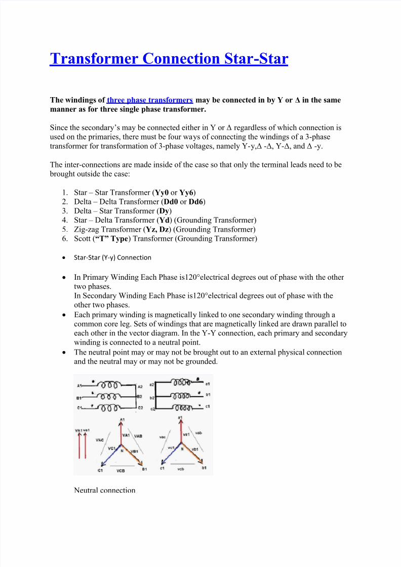
Star-Star (Y-y) Connection
In Primary Winding Each Phase is120°electrical degrees out of phase with the other
two phases.
In Secondary Winding Each Phase is120°electrical degrees out of phase with theother two phases.
Each primary winding is magnetically linked to one secondary winding through a
common core leg. Sets of windings that are magnetically linked are drawn parallel to
each other in the vector diagram. In the Y-Y connection, each primary and secondary
winding is connected to a neutral point.
The neutral point may or may not be brought out to an external physical connection
and the neutral may or may not be grounded.
Neutral connection
8/12/2019 Transformer Connection Star
http://slidepdf.com/reader/full/transformer-connection-star 2/6
Transformer magnetizing currents are not purely sinusoidal, even if the exciting
voltages are sinusoidal. The magnetizing currents have significant quantities of odd-
harmonic components. If three identical transformers are connected to each phase and
are excited by 60 Hz voltages of equal magnitude, the 60 Hz fundamental components
of the exciting currents cancel out each other at the neutral.
This is because the 60 Hz fundamental currents of A, B, and C phase are 120° out of phase with one another and the vector sum of these currents is zero.
The third, ninth, fifteenth and other so-called zero-sequence harmonic currents are in phase with each other; therefore, these components do not cancel out each other at the
neutral but add in phase with one another to produce a zero-sequence neutral current,
provided there is a path for the neutral current to flow.
Due to the nonlinear shape of the B-H curve, odd-harmonic magnetizing currents are
required to support sinusoidal induced voltages. If some of the magnetizing current
harmonics are not present, then the induced voltages cannot be sinusoidal.
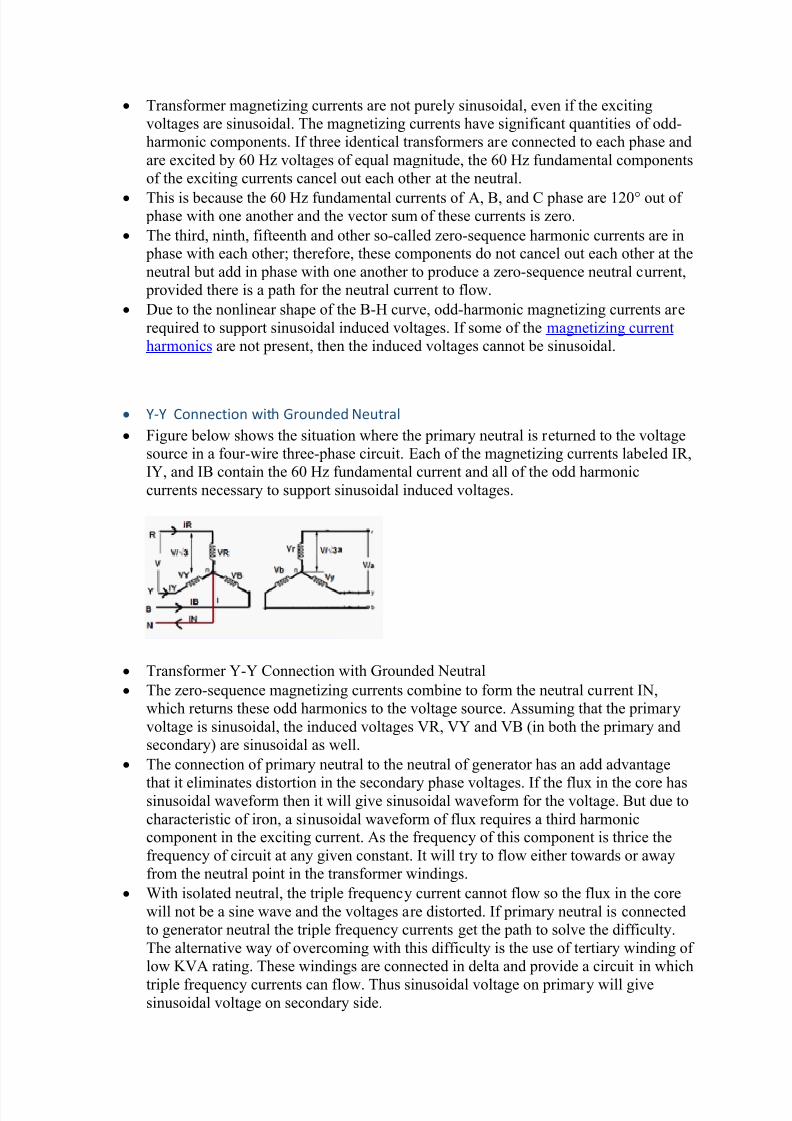
Y-Y Connection with Grounded Neutral
Figure below shows the situation where the primary neutral is returned to the voltage
source in a four-wire three-phase circuit. Each of the magnetizing currents labeled IR,
IY, and IB contain the 60 Hz fundamental current and all of the odd harmonic
currents necessary to support sinusoidal induced voltages.
Transformer Y-Y Connection with Grounded Neutral
The zero-sequence magnetizing currents combine to form the neutral current IN,
which returns these odd harmonics to the voltage source. Assuming that the primary
voltage is sinusoidal, the induced voltages VR, VY and VB (in both the primary and
secondary) are sinusoidal as well.
The connection of primary neutral to the neutral of generator has an add advantage
that it eliminates distortion in the secondary phase voltages. If the flux in the core hassinusoidal waveform then it will give sinusoidal waveform for the voltage. But due to
characteristic of iron, a sinusoidal waveform of flux requires a third harmoniccomponent in the exciting current. As the frequency of this component is thrice the
frequency of circuit at any given constant. It will try to flow either towards or away
from the neutral point in the transformer windings.
With isolated neutral, the triple frequency current cannot flow so the flux in the core
will not be a sine wave and the voltages are distorted. If primary neutral is connected
to generator neutral the triple frequency currents get the path to solve the difficulty.
The alternative way of overcoming with this difficulty is the use of tertiary winding of
low KVA rating. These windings are connected in delta and provide a circuit in which
triple frequency currents can flow. Thus sinusoidal voltage on primary will givesinusoidal voltage on secondary side.
8/12/2019 Transformer Connection Star
http://slidepdf.com/reader/full/transformer-connection-star 3/6
This situation changes if the neutrals of both sets of the primary and secondary
windings are not grounded.
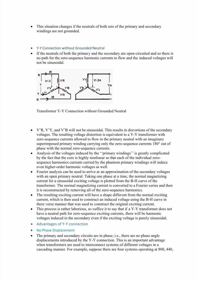
Y-Y Connection without Grounded Neutral If the neutrals of both the primary and the secondary are open-circuited and so there is
no path for the zero-sequence harmonic currents to flow and the induced voltages will
not be sinusoidal.
Transformer Y-Y Connection without Grounded Neutral
V’R, V’Y, and V’B will not be sinusoidal. This results in distortions of the secondaryvoltages. The resulting voltage distortion is equivalent to a Y-Y transformer with
zero-sequence currents allowed to flow in the primary neutral with an imaginary
superimposed primary winding carrying only the zero-sequence currents 180° out of
phase with the normal zero-sequence currents. Analysis of the voltages induced by the ‘‘primary windings’’ is greatly complicated
by the fact that the core is highly nonlinear so that each of the individual zero-
sequence harmonics currents carried by the phantom primary windings will induce
even higher-order harmonic voltages as well.
Fourier analysis can be used to arrive at an approximation of the secondary voltages
with an open primary neutral. Taking one phase at a time, the normal magnetizing
current for a sinusoidal exciting voltage is plotted from the B-H curve of the
transformer. The normal magnetizing current is converted to a Fourier series and then
it is reconstructed by removing all of the zero-sequence harmonics.
The resulting exciting current will have a shape different from the normal excitingcurrent, which is then used to construct an induced voltage using the B-H curve in
there verse manner that was used to construct the original exciting current.
This process is rather laborious, so suffice it to say that if a Y-Y transformer does not
have a neutral path for zero-sequence exciting currents, there will be harmonic
voltages induced in the secondary even if the exciting voltage is purely sinusoidal.
Advantages of Y-Y connection
No Phase Displacement
The primary and secondary circuits are in phase; i.e., there are no phase angledisplacements introduced by the Y-Y connection. This is an important advantage
when transformers are used to interconnect systems of different voltages in acascading manner. For example, suppose there are four systems operating at 800, 440,

8/12/2019 Transformer Connection Star
http://slidepdf.com/reader/full/transformer-connection-star 4/6
220, and 66 kV that need to be interconnected. Substations can be constructed using
Y-Y transformer connections to interconnect any two of these voltages. The 800 kV
systems can be tied with the 66 kV systems through a single 800 to 66 kV
transformation or through a series of cascading transformations at 440,220 and 66 kV.
Required Few Turns for winding
Due to star connection, phase voltages is (1/√3) times the line voltage. Hence less
number of turns is required. Also the stress on insulation is less. This makes the
connection economical for small high voltage purposes.
Required Less Insulation Level
If the neutral end of a Y-connected winding is grounded, then there is an opportunity
to use reduced levels of insulation at the neutral end of the winding. A winding that is
connected across the phases requires full insulation throughout the winding.
Handle Heavy Load
Due to star connection, phase current is same as line current. Hence windings have to
carry high currents. This makes cross section of the windings high. Thus the windings
are mechanically strong and windings can bear heavy loads and short circuit current.
Use for Three phases Four Wires System
As neutral is available, suitable for three phases four wire system.
Eliminate Distortion in Secondary Phase Voltage
The connection of primary neutral to the neutral of generator eliminates distortion in
the secondary phase voltages by giving path to triple frequency currents toward to
generator.
Sinusoidal voltage on secondary side
Neutral give path to flow Triple frequency current to flow Generator side thus
sinusoidal voltage on primary will give sinusoidal voltage on secondary side. Used as Auto Transformer
A Y-Y transformer may be constructed as an autotransformer, with the possibility of
great cost savings compared to the two-winding transformer construction.
Better Protective Relaying
The protective relay settings will be protecting better on the line to ground faultswhen the Y-Y transformer connections with solidly grounded neutrals are applied.
Disadvantages of Y-Y connection
The Third harmonic issue
The voltages in any phase of a Y-Y transformer are 1200 apart from the voltages inany other phase. However, the third-harmonic components of each phase will be in
phase with each other. Nonlinearities in the transformer core always lead to
generation of third harmonic.
These components will add up resulting in large (can be even larger than thefundamental component) third harmonic component.
Overvoltage at Lighting Load
The presence of third (and other zero-sequence) harmonics at an ungrounded neutral
can cause overvoltage conditions at light load. When constructing a Y-Y transformer
using single-phase transformers connected in a bank, the measured line-to-neutral
voltages are not 57.7% of the system phase-to-phase voltage at no load but are about
68% and diminish very rapidly as the bank is loaded.

8/12/2019 Transformer Connection Star
http://slidepdf.com/reader/full/transformer-connection-star 5/6
The effective values of voltages at different frequencies combine by taking the square
root of the sum of the voltages squared. With sinusoidal phase-to-phase voltage, the
third-harmonic component of the phase-to-neutral voltage is about 60%.
Voltage drop at Unbalance Load
There can be a large voltage drop for unbalanced phase-to-neutral loads. This is
caused by the fact that phase-to-phase loads cause a voltage drop through the leakage
reactance of the transformer whereas phase-to-neutral loads cause a voltage drop
through the magnetizing reactance, which is 100 to 1000 times larger than the leakage
reactance.
Overheated Transformer Tank
Under certain circumstances, a Y-Y connected three-phase trans- can produce severe
tank overheating that can quickly destroy the transformer. This usually occurs with an
open phase on the primary circuit and load on the secondary.
Over Excitation of Core in Fault Condition
If a phase-to-ground fault occurs on the primary circuit with the primary neutral
grounded, then the phase-to-neutral voltage on the un faulted phases increases to
173% of the normal voltage. This would almost certainly result in over excitation of
the core, with greatly increased magnetizing currents and core losses
If the neutrals of the primary and secondary are both brought out, then a phase-to-
ground fault on the secondary circuit causes neutral fault current to flow in the
primary circuit. Ground protection re- laying in the neutral of the primary circuit may
then operate for faults on the secondary circuit
Neutral Shifting
If the load on the secondary side unbalanced then the performance of this connection
is not satisfactory then the shifting of neutral point is possible. To prevent this, star
point of the primary is required to be connected to the star point of the generator.
Distortion of Secondary voltage
Even though the star or neutral point of the primary is earthed, the third harmonic
present in the alternator voltage may appear on the secondary side. This causes
distortion in the secondary phase voltages.
Over Voltage at Light Load
The presence of third (and other zero-sequence) harmonics at an ungrounded neutral
can cause overvoltage conditions at light load.
Difficulty in coordination of Ground Protection
In Y-Y Transformer, a low-side ground fault causes primary ground fault current,making coordination more difficult.
Increase Healthy Phase Voltage under Phase to ground Fault
If a phase-to-ground fault occurs on the primary circuit with the primary neutralgrounded, then the phase-to-neutral voltage on the UN faulted phase’s increases to173% of the normal voltage.
If the neutrals of the primary and secondary are both brought out, then a phase-to-ground fault on the secondary circuit causes neutral fault current to flow in the
primary circuit.
Trip the T/C in Line-Ground Fault
All harmonics will propagate through the transformer, zero-sequence current path iscontinuous through the transformer, one line-to-ground fault will trip the transformer.

8/12/2019 Transformer Connection Star
http://slidepdf.com/reader/full/transformer-connection-star 6/6
Suitable for Core Type Transformer
The third harmonic voltage and current is absent in such type of connection with three phase wire system. or shell type of three phase units, the third harmonic phase voltage
may be high. This type of connection is more suitable for core type transformers.
Application
This Type of Transformer is rarely used due to problems with unbalanced loads.
It is economical for small high voltage transformers as the number of turns per
phase and the amount of insulation required is less.