Embed Size (px)
Citation preview

TRANSDUCERIZEDFIXTURED NUTRUNNER
AU50MAXIS Control Unit
Z50 series
● The colors of the products may slightly differ from those of the actual products, which is inevitable in printing.● The specifications and designs of the products may be changed without prior notice.
The contents of the catalog are as of April, 2021.
This catalog uses vegetableoil ink.
Head Of�ce & Osaka Sales Of�ce
1-2-16, Togodori, Moriguchi-shi, Osaka, 570-0041, JapanPhone: +81-6-6993-8855 Fax: +81-6-6993-8875E-mail: osaka_of�[email protected]
Tokyo Sales Of�ce 2F Shinyokohama Bousei Bldg., 3-20-12 Shin-Yokohama, Kouhoku-ku, Yokohama-shi, Kanagawa Pref. 222-0033, JapanPhone: +81-45-474-3036 Fax: +81-45-474-3037E-mail: tokyo_of�[email protected]
Chubu Sales Of�ce
SUBSIDIARIES
Honda Bldg., 2-28, Kouseidori-minami, Okazaki-city, Aichi, 444-0044 JapanPhone: +81-564-66-0510 Fax: +81-564-66-0515E-mail: chubu_of�[email protected]
Hashiba Plant 2-5-9 Hashibahigashino-cho, Moriguchi City, Osaka, 570-0031 JapanPhone: +81-6-6993-8834 Fax: +81-6-6993-8881
Togo Plant 1-2-16, Togodori, Moriguchi-shi, Osaka, 570-0041, JapanPhone: +81-6-6993-8077 Fax: +81-6-6993-8887
SHANGHAI ESTIC CO., LTD. No. 6, 51 Gate, 1159 Lane, Kangqiao East Road, Pudong, Shanghai, 201315 ChinaPhone: +86-21-6813-0333 Fax: +86-21-6813-0777E-mail: [email protected]
ESTIC (THAILAND) CO., LTD.
Head Of�ceESTIC AMERICA, INC.
19 Naradhiwas Rajanakarin Road, Chong Nonsi, Yannawa, Bangkok, 10120, ThailandPhone: +66-2-678-0171 Fax: +66-2-678-0173E-mail: [email protected]
1895 Airport Exchange Blvd., Suite 220, Erlanger, Kentucky, 41018 U.S.A.Phone: +1-859-746-8800 Fax: +1-859-746-8777E-mail: [email protected]
Novi Technical Center 25901 Meadowbrook Rd. Novi, Michigan, 48375, U.S.A.Phone: +1-248-719-7622
www.estic.co.jpESTIC CORPORATION
JQA-2805SERVO SYSTEM

21
Durability
High
Reliability
Stable thread
fastening
Monitoring functionsto keep watch overfastening quality
Finest fastening
accuracy
Networking
Extensibility
Easy operation Traceability
Multi spindle fasetning machine
High performance, high reliability Fixtured Nutrunner System
The innovative component for bolt and nut tightening process
・Self-diagnosis function on each fastening・Double structure torque monitoring
Torque is not only monitored by the torque sensor, but also by current. Fastening operations are monitored, and crucial data, such as torque, angle and time is recorded.
Fastening results with VIN information produced and reported by Fastening systems, calibrated with the national standard traceable methodFastening result data and torque curve data are available and stored for traceability and analysis purposes.
Extremely high durability to maximize the operation time
Equipped wi th h igh durab i l i t y reducer gear and resolver.
Various networking options areavailable such as Ethernet, and Fieldbus
Possible to communicate with PLC, Factory automation system by complying with various types of communication protocols.
Torque rate function monitorsincrease ratio of torque and angle.
By monitoring the increasing ratio of torque and angle, the system judges abnorma l fas ten ings , and rea l i zes certainty of fastening process.
Leak of torque typically seen on soft joints can be minimized by using the Dynamic S t a l l f u n c t i o n a n d t h e S e q u e n c e d fastening program.
State of the art servo motor and feedback control by high speed process realize high dynamic accuracy of 3σ/X ≦ 2%(at Full Scale).
Management Software, and Touch Screens are available for easy setup and operation. User friendly software allows operators to program various parameters such as fastening programs, as well as collect fastening results and torque curve data.
ESTIC's nutrunner system realizes the highest level of accuracy, motor responsiveness,
durability, and is suitable for various thread fastening operations which require traceability.
Fixtured Nutrunner SystemELECTRIC FIXTURED NUTRUNNER
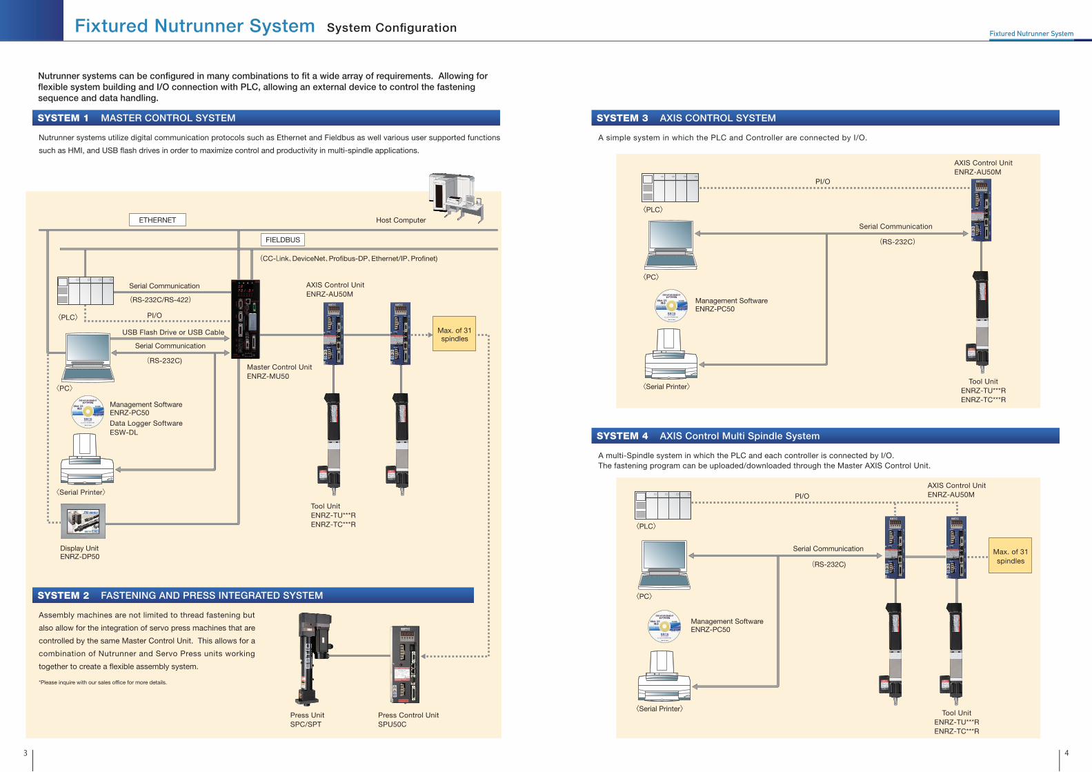
Fixtured Nutrunner SystemFixtured Nutrunner System System Configuration
MASTER CONTROL SYSTEMSYSTEM 1 AXIS CONTROL SYSTEMSYSTEM 3
Nutrunner systems utilize digital communication protocols such as Ethernet and Fieldbus as well various user supported functions
such as HMI, and USB �ash drives in order to maximize control and productivity in multi-spindle applications.
Assembly machines are not limited to thread fastening but
also allow for the integration of servo press machines that are
controlled by the same Master Control Unit. This allows for a
combination of Nutrunner and Servo Press units working
together to create a �exible assembly system.
A simple system in which the PLC and Controller are connected by I/O.
AXIS Control Multi Spindle SystemSYSTEM 4
ETHERNET
Serial Communication
USB Flash Drive or USB Cable
(RS-232C)
Serial Communication
Master Control UnitENRZ-MU50
(RS-232C/RS-422)
FIELDBUS
AXIS Control UnitENRZ-AU50M
Tool UnitENRZ-TU***RENRZ-TC***R
Press UnitSPC/SPT
Press Control UnitSPU50C
(CC-Link、DeviceNet、Pro�bus-DP、Ethernet/IP、Pro�net)
PI/O
〈Serial Printer〉
〈PC〉
〈PLC〉
Host Computer
Max. of 31spindles
Max. of 31spindles
Display UnitENRZ-DP50
Data Logger SoftwareESW-DL
Management SoftwareENRZ-PC50
PI/O
Serial Communication
(RS-232C)
〈Serial Printer〉
〈PC〉
〈PLC〉
Management SoftwareENRZ-PC50
AXIS Control UnitENRZ-AU50M
Tool UnitENRZ-TU***RENRZ-TC***R
PI/O
〈Serial Printer〉
〈PC〉
〈PLC〉
AXIS Control UnitENRZ-AU50M
Tool UnitENRZ-TU***RENRZ-TC***R
A multi-Spindle system in which the PLC and each controller is connected by I/O. The fastening program can be uploaded/downloaded through the Master AXIS Control Unit.
Nutrunner systems can be configured in many combinations to fit a wide array of requirements. Allowing for flexible system building and I/O connection with PLC, allowing an external device to control the fastening sequence and data handling.
Serial Communication
(RS-232C)
Management SoftwareENRZ-PC50
FASTENING AND PRESS INTEGRATED SYSTEMSYSTEM 2
3 4
*Please inquire with our sales of�ce for more details.

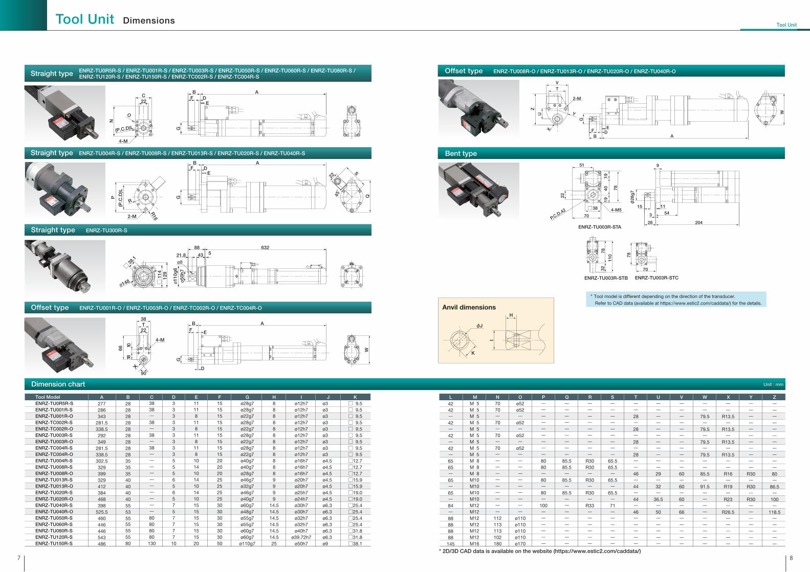
Straight typeCompact, high performance tool unit.
Small high power servo motor developed
for the Nutrunner with a built-in precision
torque transducer.
Offset typeOffset gears are built-in for narrow
pitch, multi spindle applications
Bent typeBuilt-in gear train reduces height for
applications with height limitations.
Torque transducer
Anvil
Reducer Gear
Servo motor
Resolver
Torque transducer
Offset gear
Anvil
Reducer Gear
Servo motor
Resolver
Torque transducer
Anvil
Reducer Gear
Servo motor
Gear train
Durable, high speed, high accuracy tool unit in a small form factor.▶Highly accurate torque detection is realized by 8 strain gauge type torque transducer with
noise cancellation function.
▶A wide torque range from 0.5Nm up to 3000Nm is covered.
▶Suitable for various applications with Straight type, Offset type, Bent type, Angle head type.
* Weight in ( ) is for offset type.
Tool Type
Tool Unit Model
Rated Torque
ENRZ-TU 001R-S
S:Straight type ST: Straight Bent typeO:Offset type OP:Offset Bent type
Tool Unit Basic Speci�cations
TU:Standard tools TC:High speed Light-weight tools
Straight tool Offset tool
ENRZ-TU001R-O
ENRZ-TU003R-O
ENRZ-TU008R-O
ENRZ-TU013R-O
ENRZ-TU020R-O
ENRZ-TU001R-S
ENRZ-TU003R-S
ENRZ-TU008R-S
ENRZ-TU013R-S
ENRZ-TU020R-S
ENRZ-TU040R-S
ENRZ-TU120R-S
* Max. tightening capacity of Bent type is 80%
of Straight/Offset type.
Model
Rated Torque (Nm)Applicable Torque Range (Nm)Max. Speed (rpm)Torque converter
Torque Display Resolution (Nm)Angle detector
Angle Display Resolution (deg)Dynamic Torque Accuracy
Weight (Kg) Corresponding Controller type
Straight type
Offset type
5
0.5-4.5
3940
Strain gauge type torque transducer with ampli�er built-in
0.01
Resolver
0.1
3σ/X ≦ 2%(FS)1.7
ENRZ-AU50M-10
ENRZ-TU0R5R-S
―10
1-9
1714
0.01
1.9(2.3)
ENRZ-TU001R-S
ENRZ-TU001R-O
20
2-18
1960
0.01
1.8(2.2)
ENRZ-AU50M-20
ENRZ-TC002R-S
ENRZ-TC002R-O
30
3-27
655
0.01
1.9(2.3)
ENRZ-AU50M-10
ENRZ-TU003R-S
ENRZ-TU003R-O
40
4-36
1120
0.01
1.8(2.2)
ENRZ-AU50M-20
ENRZ-TC004R-S
ENRZ-TC004R-O
40
4-36
2050
0.01
3.8
ENRZ-TU004R-S
―80
8-72
1000
0.01
4.2(4.7)
ENRZ-AU50M-20
ENRZ-TU008R-S
ENRZ-TU008R-O
130
13-117
700
0.01
4.2(5.2)
ENRZ-TU013R-S
ENRZ-TU013R-O
200
20-180
407
0.1
5.5(6.5)
ENRZ-TU020R-S
ENRZ-TU020R-O
400
40-360
207
0.1
6.3(9.3)
Strain gauge type torque transducer with ampli�er built-in
Resolver
0.1
3σ/X ≦ 2%(FS)
ENRZ-TU040R-S
ENRZ-TU040R-O
600
60-540
158
0.1
12
ENRZ-AU50M-40
ENRZ-TU060R-S
―800
80-720
116
0.1
12
ENRZ-TU080R-S
―500
50-450
405
0.1
11.3
ENRZ-AU50M-5K2
ENRZ-TU050R-S
―1200
120-1080
117
0.1
14.3
ENRZ-AU50M-5K2
ENRZ-TU120R-S
―3000
300-2700
39
1
22.6
ENRZ-AU50M-5K2
ENRZ-TU300R-S
―1500
150-1350
60
0.1
32.5
ENRZ-AU50M-2K
ENRZ-TU150R-S
―
Model
Tool models
5 6
Tool UnitTool Unit
0R5: 5 N・m 001: 10 N・m 002: 20 N・m003: 30 N・m004: 40 N・m
008: 80 N・m013: 130 N・m020: 200 N・m040: 400 N・m050: 500 N・m
060: 600 N・m080: 800 N・m120:1200 N・m150:1500 N・m300:3000 N・m
7 8
M N O P Q R S T U V W X Y ZA B C D E F G H I J K
Dimension chart Unit : mm
L
* 2D/3D CAD data is available on the website (https://www.estic2.com/caddata/)
Tool ModelENRZ-TU0R5R-SENRZ-TU001R-SENRZ-TU001R-OENRZ-TC002R-S ENRZ-TC002R-O ENRZ-TU003R-SENRZ-TU003R-OENRZ-TC004R-S ENRZ-TC004R-O ENRZ-TU004R-SENRZ-TU008R-SENRZ-TU008R-OENRZ-TU013R-SENRZ-TU013R-OENRZ-TU020R-SENRZ-TU020R-OENRZ-TU040R-SENRZ-TU040R-OENRZ-TU050R-SENRZ-TU060R-SENRZ-TU080R-SENRZ-TU120R-SENRZ-TU150R-S
M 5M 5M 5M 5M 5M 5M 5M 5M 5M 8M 8M 8M10M10M10M10M12M12M12M12M12M12M16
7070ー70ー70ー70ーーーーーーーーーー
112113113102180
ø52ø52ー
ø52ー
ø52ー
ø52ーーーーーーーーーー
ø110ø110ø110ø110ø170
ーーーーーーーーー8080ー80ー80ー
100ーーーーーー
ーーーーーーーーー
85.585.5ー
85.5ー
85.5ーーーーーーーー
ーーーーーーーーー
R30R30ー
R30ー
R30ー
R33ーーーーーー
ーーーーーーーーー
65.565.5ー
65.5ー
65.5ー71ーーーーーー
ーー28ー28ー28ー28ーー46ー44ー44ー46ーーーーー
ーーーーーーーーーーー29ー32ー
36.5ー50ーーーーー
ーーーーーーーーーーー60ー60ー60ー66ーーーーー
ーー
79.5ー
79.5ー
79.5ー
79.5ーー
85.5ー
91.5ーーーーーーーーー
ーー
R13.5ー
R13.5ー
R13.5ー
R13.5ーー
R16ー
R19ー
R23ー
R26.5ーーーーー
ーーーーーーーーーーー
R30ー
R30ー
R30ーーーーーーー
ーーーーーーーーーーー80ー
86.5ー
100ー
118.5ーーーーー
277286343
281.5338.5292349
281.5338.5302.5329399329412384468398
525.5460446446543486
2828282828282828283535354040404055535555555580
3838ー38ー38ー38ーーーーーーーーーー80808080130
333333333555656575777710
11118
118
118
118
1014101410141015151515151520
1515151515151515152020202525252530303030303050
ø28g7ø28g7ø22g7ø28g7ø22g7ø28g7ø22g7ø28g7ø22g7ø40g7ø40g7ø28g7ø46g7ø32g7ø46g7ø40g7ø60g7ø48g7ø55g7ø55g7ø60g7ø60g7
ø110g7
8888888888889999
14.514.514.514.514.514.525
ø12h7ø12h7ø12h7ø12h7ø12h7ø12h7ø12h7ø12h7ø12h7ø16h7ø16h7ø16h7ø20h7ø20h7ø25h7ø24h7ø30h7ø30h7ø32h7ø32h7ø40h7
ø39.72h7ø50h7
ø3ø3ø3ø3ø3ø3ø3ø3ø3ø4.5ø4.5ø4.5ø4.5ø4.5ø4.5ø4.5ø6.3ø6.3ø6.3ø6.3ø6.3ø6.3ø9
□ 9.5□ 9.5□ 9.5□ 9.5□ 9.5□ 9.5□ 9.5□ 9.5□ 9.5□12.7□12.7□12.7□15.9□15.9□19.0□19.0□25.4□25.4□25.4□25.4□31.8□31.8□38.1
4242ー42ー42ー42ー6565ー65ー65ー84ー88888888145
W
2-M
V
U Y
X
B A
T
EDF
G
Z
Anvil dimensions
I
H
K
φJ
78
70
ENRZ-TU003R-STC
110
3278
ENRZ-TU003R-STB
51
22
1919
4-M570
□38
40 78
P.C.D.42
ENRZ-TU003R-STA
9
11
φ28
g7
54
28
15
204
3
N
E22
ABF D
G(P.C.D)L
O
C
4-M
Q45゚
SEF
R16
R
22
(P.C
.D)L
B AD
GP
2-M
22
W
A
E
B
D
F
G
T38
90゚
X
4-M
18
66
10
ø148
129
□ 38
.1
□ 1
14
88 6325
ø50h
7ø1
10g
6
21.8 43
ø8
Offset type ENRZ-TU008R-O / ENRZ-TU013R-O / ENRZ-TU020R-O / ENRZ-TU040R-O
Bent type
* Tool model is different depending on the direction of the transducer.
Refer to CAD data (available at https://www.estic2.com/caddata/) for the details.
Straight type ENRZ-TU0R5R-S / ENRZ-TU001R-S / ENRZ-TU003R-S / ENRZ-TU050R-S / ENRZ-TU060R-S / ENRZ-TU080R-S /
Straight type ENRZ-TU004R-S / ENRZ-TU008R-S / ENRZ-TU013R-S / ENRZ-TU020R-S / ENRZ-TU040R-S
Straight type ENRZ-TU300R-S
Offset type ENRZ-TU001R-O / ENRZ-TU003R-O / ENRZ-TC002R-O / ENRZ-TC004R-O
ENRZ-TU120R-S / ENRZ-TU150R-S / ENRZ-TC002R-S / ENRZ-TC004R-S
Tool UnitTool Unit Dimensions

Socket Assembly Socket Adapter
Reference drawing for mounting a socket assembly (the arrows A to A)
5, 10, 20, 30, 40NmFor Straight tool
40, 80NmFor Straight tool
130NmFor Straight tool
200NmFor Straight tool
400NmFor Straight tool
400NmFor Offset tool
500, 600NmFor Straight tool
10, 20, 30, 40NmFor Offset tool
80NmFor Offset tool
130NmFor Offset tool
200NmFor Offset tool
800, 1200NmFor Straight tool (*1)
TNA1-SA02-30 TNA1-SA05-35 TNA1-SA20-45C TNA1-SA20-45Z TNA1-SA40-70 TNA1-SA80-80
ENRZ-SA150-120
1500NmFor Straight tool
(*1) Please design so as to have counterbore holes for the tool mounting bolts on the tool mounting plate.
In addition, please design not to interefere the tool mounting bolts and the socket assembly �ange.
Mounting plate
A A
How to mount a nutrunner
9 10
Model Adapter insertion angleApplicable tool unit
ENRZ-TU0R5R-S
ENRZ-TU001R-S/O
ENRZ-TU003R-S/O
ENRZ-TC002R-S/O
ENRZ-TC004R-S/O
ENRZ-TU004R-S
ENRZ-TU008R-S/O
ENRZ-TU013R-S/O
ENRZ-TU020R-S/O
ENRZ-TU040R-S/O
ENRZ-TU050R-S
ENRZ-TU060R-S
ENRZ-TU080R-S
ENRZ-TU120R-S
ENRZ-TU150R-S
TNA1-SA02-30*
TNA1-SA05-35
TNA1-SA20-45C
TNA1-SA20-45Z
TNA1-SA40-70
TNA1-SA80-80
ENRZ-SA150-120
□ 9.5
□ 12.7
□ 15.9
□ 15.9
□ 25.4
□ 31.8
□ 38.1* Please consult with us when it is used for tightening above 36Nm.
Model Socket assembly side - Socket side
□ 9.5ー□ 9.5
□ 12.7ー□ 12.7
□ 12.7ー□ 9.5
□ 15.9ー□ 15.9
□ 15.9ー□ 12.7
□ 15.9ー□ 19
□ 25.4ー□ 25.4
□ 25.4ー□ 19
□ 31.8ー□ 31.8
□ 31.8ー□ 25.4
□ 38.1ー□ 38.1
□ 38.1ー□ 25.4
TNA1-AD01-01
TNA1-AD05-01
TNA1-AD05-02
TNA1-AD20-01
TNA1-AD20-02
TNA1-AD20-03
TNA1-AD40-01
TNA1-AD40-02
TNA1-AD80-01
TNA1-AD80-02
ENRZ-AD150-01
ENRZ-AD150-02
Tool unit and socket assemblyare secured with bolts fromthe direction of view A-A.
Tool UnitTool Unit Socket Assembly & Socket Adapter

Table of dimensions for Socket Assembly
Table of dimensions for Socket Adapter
Socket Assembly external dimensions Socket Adapter external dimensions
Tool Unit Socket Assembly & Socket Adapter Tool Unit
Unit : mm
Unit : mm
TNA1-AD**-03 TNA1-AD**-02ENRZ-AD***-02
TNA1-AD**-01ENRZ-AD***-01
ab
ba
g
d
fc
h e
g
d
fc
h e
g
d
fc
h e
a
11 12
TNA1-SA05-35TNA1-SA20-45CTNA1-SA20-45Z
TNA1-SA40-70TNA1-SA80-80TNA1-SA02-30 ENRZ-SA150-120
P(
P.C
.D)H
P(P
.C.D
)H
UVS
W
T
W
W
45°
Q
2-R
Q
Q
2-R
2-R
2-F drill hole
2-F drill hole
2-F drill hole
H
P
A
Socket
Dowel (accessary)
Grease nipple
Mounting plate
Needle bearing
M
Socket Adapter
O-ring
O
N
K
L
(G)
JC
B
Y X
X : Initial load at home position (N)Y : Load at stroke end position (N)Z : Spring rate (N/mm)
I
D
E
Model A□ 9.5
□12.7
□15.9
□15.9
□25.4
□31.8
□38.1
TNA1-SA02-30
TNA1-SA05-35
TNA1-SA20-45C
TNA1-SA20-45Z
TNA1-SA40-70
TNA1-SA80-80
ENRZ-SA150-120
Nφ28g7
φ40g7
φ46g7
φ46g7
φ60g7
φ80g7
φ110g7
B30
35
45
45
70
80
120
Oφ18g7
φ25g7
φ32g7
φ32g7
φ45g7
φ55g7
φ70g7
C3
3
3
3
3
5
6
P55
55
65
65
100
128
230
D155
182
212
212
309
340
454
QR15
R21
R24
R24
R31
R42
R65
E153
179
209
209
300
331
449
RR 5
R 6
R 7.5
R 7.5
R 8
R 10
R115
Fφ 6.5
φ 7
φ 9
φ 9
φ11
φ14
φ18
S―13
16
16
――φ25
G(12)
(12)
(12)
(12)
(16)
(16)
(25)
T―7
8.5
8.5
―――
H45
43
50
50
84
108
200
U―
21
22.5
22.5
――
130
I109
136
153
153
219
230
294
V―
21.5
22.5
22.5
―――
J8
10
12
12
15
16
20
W19.5
25
29
29
36
43
57
Kφ 30
φ 40
φ 48
φ 48
φ 62
φ 76
φ105
X13.5
14.2
18.1
18.1
27.5
47
39.2
L5.5
8
9
9
15
16.5
19
Y23.2
25.5
34.5
34.5
43.6
77.4
74.1
Mφ4
φ4.5
φ6
φ6
φ7.5
φ7.5
φ9
Model a□ 9.5
□12.7
□12.7
□15.9
□15.9
□15.9
□25.4
□25.4
□31.8
□31.8
□38.1
□38.1
b――□ 9.5
―□12.7
□19
―□19
―□25.4
―□25.4
c5.5
8
8
9
9
9
15
15
16.5
16.5
19
19
d12
17
12
20
17
20
30
20
30
30
39
30
eφ4
φ5
φ4
φ6
φ5
φ6.5
φ7.5
φ6
φ7.5
φ7.5
φ9
φ7.5
f5.5
8
5.5
9
8
11
15
11
16.5
15
19
15
g24
34
29
40
37
40
60
50
60
60
78
69
hφ4
φ5
φ5
φ6
φ6
φ6
φ7.5
φ7.5
φ7.5
φ7.5
φ9
φ9
Weight (g) 15
37
26
66
51
82
272
186
434
354
833
555
TNA1-AD01-01
TNA1-AD05-01
TNA1-AD05-02
TNA1-AD20-01
TNA1-AD20-02
TNA1-AD20-03
TNA1-AD40-01
TNA1-AD40-02
TNA1-AD80-01
TNA1-AD80-02
ENRZ-AD150-01
ENRZ-AD150-02
Z0.323
0.323
0.362
0.362
0.225
0.362
0.291
Dowel (accessary)
φ3x16
φ4x20
φ5x25
φ5x25
φ6x40
φ6x50
φ6x60
O-ring
P16
P22
P29
P29
P42
P52
P63
Weight (kg)
0.5
1.0
1.3
1.3
3.6
9.6
16.5
UW
4-S drill hole
6-F drill hole
R
(P
.C.D)H
P
* 2D/3D CAD data is available on the website (https://www.estic2.com/caddata/)

13
T=KdN T=Torque (Nm) N=Axial Force (N) K=Torque Coefficient d=Nominal Bolt Diameter (m)
With bolt fastening, a fastening force is generated between the parts by the application of a fastening torque. With T as the fastening torque and N as the fastening force (axial force) generated between the parts. The relationship is as shown below when the part and the fastened object are within the elastic limit.
snug
K changes depending on the connection state between the thread and bolt seat surface. There is considerable scatter even for bolts and tapping even when manufactured under the same conditions.As shown in the �gure on the left, when fastening to the target torque T with the torque method, the axial force of the bolt shows the scatter N1 because of the difference in torque coef�cient, even when the torque is constant.However, with the angle method fastening for the constant angle ø1 from the snug point, the scatter of the axial force becomes N2, which is smaller than with the torque method. When the fastening angle is made ø2 and fastening is performed within the elastic range of the bolt, the scatter of the axial force becomes N3, which is still smaller. Accordingly, for execution of fastening without loosening, it is necessary to select the fastening method according to the fastening conditions for the object to be fastened and the conditions at the time of product design.
Fastening Theory
Torque Control Angle Control
Torque T
Axial force N
Torque T
Snag p
ointtorq
ueA
xial force N
Control pointtorque
Large torquecoef�cient
Small torquecoef�cient
Large torquecoef�cient
Small torquecoef�cient
Angle Angle
1
1
2
2
N1 N2
N3
14
Fastening strategiesThis fastening method brings out the tension (clamping force) of a bolt to its greatest extent. The yield point is obtained from the torque increase rate (torque rate), fastening is performed for the set angle from this point and fastening is completed in a stable plastic region initial state.Sampling of the angle data is started from the point at which the ANG start torque is detected. When the snug torque is detected, fastening is performed while calculating the torque rate. Additional fastening is performed for the target angle from the point at which the target torque rate is detected, and then fastening is completed.When the lower limit angle is not reached at the completion of additional fastening after the detection of the yield point, additional fastening is performed again until the lower limit angle has been reached.
6 Yield Angle Control
Basically, this method performs the same control as the yield angle method. In this case, when the lower limit angle is not reached at the completion of additional fastening after the detection of the yield point, additional fastening is not performed and the step terminates due to fastening NG.
7 Yield Control
This fastening method is commonly used. Fastening is stopped when a prede�ned target torque has been reached. Judgment is made if the peak torque is within range of the upper and lower limit. If the fastening falls within the prede�ned range then an OK result is produced. If the fastening exceeds or falls short of the range then an NG judgment is made. With this system total judgment is performed by measuring the upper and lower limit of fastening time, as well as upper and lower limit for torque.
1 Torque Control
Fastening is performed establishing an upper and lower limit for torque, as well as creating an upper and lower limit for angle.
2 Torque Control Angle Monitor
With this fastening method, fastening is performed from an angle measuring start torque until an optionally set fastening target angle has been reached. Fastening is then stopped, and judgment is made. If the angle and torque value are within the range between the set upper and lower limit, then an OK or NG (for each value) is produced.
3 Angle Control
Yield Point
Yield Angle
Torque
OK Zone
Timeor
Angle
Upper Torque Limit
Lower Torque Limit
Angle StartTorque
Angle or Time
Angle
OK Zone
Torque
Target Torque
Lower Angle Limit
Upper Angle Limit
Upper Time Limit
Lower Time Limit
Torque Upper Torque Limit
Lower Torque Limit
Lower Time Limit
Upper Time Limit
Target Torque
Time
OK Zone
Target Torque Rate
Snug Torque
Angle StartTorque
Upper Angle Limit
Target Torque RateFilter Angle
Lower Angle Limit
Upper Torque Limit
Lower Torque Limit
Target Angle
TorqueTarget Angle
Upper Torque Limit
Lower Torque Limit
Angle StartTorque
Angle or Time
OK Zone
Lower Angle Limit
Upper Angle Limit
Upper Time Limit
Lower Time Limit
Yield Point
Yield Angle
Torque
OK Zone
Timeor
Angle
Upper Torque Limit
Lower Torque Limit
Target Torque RateSnug Torque
Angle StartTorque
Upper Angle Limit
Target Torque RateFilter Angle
Lower Angle Limit
Target Angle
Basically, this control method is similar to the torque method angle monitor, but the stop control condition for the target is effective for the target torque and the target angle, and the output axis is stopped when one of the target values has been reached.
4 Torque or Angle Control
Unlike the torque or angle method, when both of the target torque and target angle is detected,the output spindle is stopped and a judgement is made. When the upper limit torque, upper limit angle or upper limit time is exceeded during execution, the step terminates due to fastening NG.
5 Torque and Angle Control
Angle StartTorque
Angle or Time
OK Zone
Torque Target Angle
Target Torque
Upper Torque Limit
Lower Torque Limit
Upper Time Limit
Lower Time Limit Upper Angle Limit
Lower Angle Limit
Tool UnitTool Unit 7 fastening strategies

Model A
205
205
205
208
B
74
87
117
117
C
255
255
274
298
D
37
41
41
62
E
50
50
50
80
F
245
245
245
288
ENRZ-AU50M-10
ENRZ-AU50M-20
ENRZ-AU50M-40
ENRZ-AU50M-2K
ENRZ-AU50M-5K2
General Specifications
Model
Motor type on tool unit
Control power voltage
Main power voltage
Operation environment
Operating temperature
Operating humidity
Operation & Display Panel
Control Input
Control Output
Fastening Program
NET Port
COM Port
Recommended printer
Control Power Capacity
Main Power Capacity (At Rated Operation)
Dash Current when applying Control power
Dash Current when applying Main powe
Weight
External DimensionsUnit : mm
Previous tool models (ENRZ-TU***-*) and Encoder cable
(ENRZ-CVEN-***) are compatible with this controller.
Backward compatible
Free run speed of Resover tool (ENRZ-TU***R-*) is signi�cantly improved.
[140% faster than the conventonal series]
* Tool model ENRZ-TU150R-S Free run speed is unchanged from AU50R system.
Speed boost function
Fastening program: 99
Fastening result: 5,115 records
System error: 50 records
Storage function
Torque control, Angle control, Yield control and more are
available as standard functions.
Various fastening strategies
ENRZ-AU50M-10
100W
Single phase AC200~230V±10% 50/60Hz
0.4KVA
About 23 Ao-p (Converging Time: About 200ms)
2.5kg
ENRZ-AU50M-20
200W
1.2KVA
3.2kg
ENRZ-AU50M-40
400W
1.7KVA
3.4kg
ENRZ-AU50M-2K
2400W
3.8KVA
3.5kg
ENRZ-AU50M-5K2
5000W
8.0KVA
5.6kg
5.2
100
FC
5
B
E
D
A
L3
L1L2C
L2
L1C
ALM
CONT
ROL
RS23
2CSI
GNA
LT/
T
NGOK
RS48
5-NE
T
VU
POWER
CHARGE
MOTOR
W
INSPECTION2ND1ST
ø5.2
ø9.5
This control unit was developed for a single spindle.
It accomplishes high accuracy, high quality fastening with simple configuration
parameters. Monitor functions required for fastening come standard, and judgment
is determined by torque, angle, time, or torque rate.
Front Panel Wiring
Data Display・Real time torque value indication
・Final torque indication
・System error message indication
・Setting Parameter
・Test mode
・Log mode
Torque Transducer Cable
Indicator lamp・Fastening OK: Green
・Alarm: Yellow
・Fastening NG: Red
Resolver Cable
Operation button・Mode change
・Display change
・Parameter edit and set
* The connection port of ENRZ-AU50M-5K2 is a screw terminal block.
Charge lamp
Power supplycable
Motor cable *
Ground
Motor power supply and control
power supply are separated
NET CableThis is used when multi spindle system is
configured
I/OInput 12 Output 22
The sync (NPN, -Common) or
the source (PNP, +Common)
RS-232CThis is used to communicate with
Management Software and it is also
possible to connect with serial printer
Single phase AC200~230V±10% 50/60Hz
Free from corrosive/explosive gasses, dust/metal dust or oil mist.
0~55˚C (No freezing)35~90%RH (No condensing)
7 Segment LED Display (5 letters x 1 line), 5 Function keys, Indicator lamps (OK/ALM/NG)
12 points, Photo Coupler Isolation (DC24V, Lead-in Current: 6mA/point) * The sync (NPN, -Common) or the source (PNP, +Common)
Photo MOS output 22 points (DC24V, max. 50mA/point) * The sync (NPN, -Common) or the source (PNP, +Common)
99 Programs
RS-485 x 2 ports (MAX. Connected Stations: 31 stations)
RS-232C x 1 port (Variable between: 9600bps – 115.2kbps)
Serial Printer EPSON VP-700
About 26 Ao-p (Converging Time: About 5ms)
About 6 Ao-p(Converging Time: About 400ms)
Three phase AC200~230V±10% 50/60Hz
50VA
1615
AXIS Control UnitAXIS CONTROL UNIT
Management SoftwareProcess Control
ServerSwitch Hub
MU50 MU50 MU50 MU50
Ethernet Port comes standard. It connects to LAN and allows for communication between 1 PC and multiple Master Control Units.
Fastening Program: 99Fastening result: 20,000 recordsTorque curve: 50 recordsSystem error: 200 records
DeviceNet, Ethernet/IP, Pro�bus-DP, Pro�net, CC-Link are available as options.
1. Seizing Monitor
3. Self Tapping Monitor
2. Section Monitor
5. Back Rate Monitor
Torque
Angle
Back RateFilter Angle
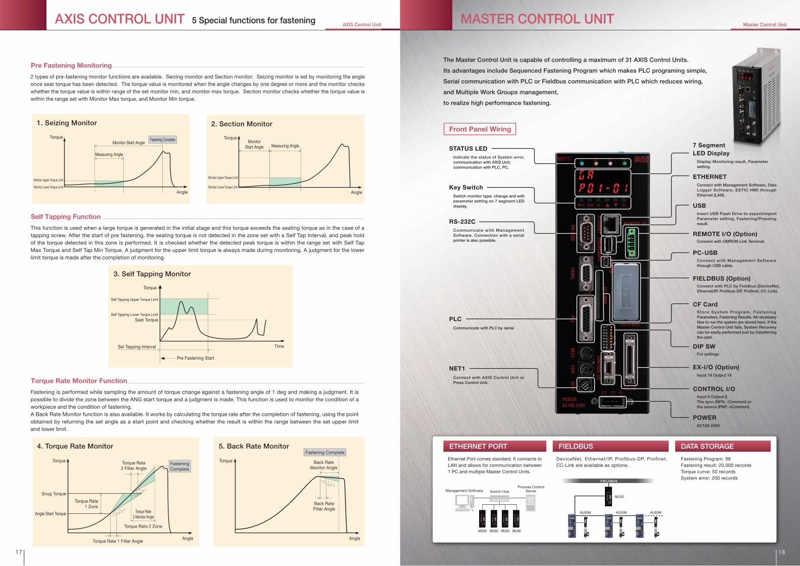
Pre Fastening Monitoring
2 types of pre-fastening monitor functions are available. Seizing monitor and Section monitor. Seizing monitor is set by monitoring the angle once seat torque has been detected. The torque value is monitored when the angle changes by one degree or more and the monitor checks whether the torque value is within range of the set monitor min, and monitor max torque. Section monitor checks whether the torque value is within the range set with Monitor Max torque, and Monitor Min torque.
Self Tapping Function
This function is used when a large torque is generated in the initial stage and this torque exceeds the seating torque as in the case of a tapping screw. After the start of pre fastening, the seating torque is not detected in the zone set with a Self Tap Interval, and peak hold of the torque detected in this zone is performed. It is checked whether the detected peak torque is within the range set with Self Tap Max Torque and Self Tap Min Torque. A judgment for the upper limit torque is always made during monitoring. A judgment for the lower limit torque is made after the completion of monitoring.
Torque Rate Monitor Function
Fastening is performed while sampling the amount of torque change against a fastening angle of 1 deg and making a judgment. It is possible to divide the zone between the ANG start torque and a judgment is made. This function is used to monitor the condition of a workpiece and the condition of fastening. A Back Rate Monitor function is also available. It works by calculating the torque rate after the completion of fastening, using the point obtained by returning the set angle as a start point and checking whether the result is within the range between the set upper limit and lower limit.
TorqueTorque
Angle Angle
Pre Fastening Start
Torque
Time
Self Tapping Upper Torque Limit
Self Tapping Lower Torque Limit
Seat Torque
Sel Tapping Interval
MonitorStart Angle Measuring Angle
Monitor Start Angle
Measuring Angle
Monitor Upper Torque Limit
Monitor Lower Torque Limit
Monitor Upper Torque Limit
Monitor Lower Torque Limit
Fastening Complete
Torque Rate 2 Zone
4. Torque Rate Monitor
Torque
Angle
Snug Torque
Torque Rate2 Filter Angle
Torque Rate 1 Filter Angle
Torque Rate2 Monitor Angle
Angle Start Torque
Torque Rate1 Zone
Fastening Complete
FasteningComplete
Back RateMonitor Angle
17 18
FIELDBUS
AU50M AU50M AU50M
MU50
The Master Control Unit is capable of controlling a maximum of 31 AXIS Control Units.
Its advantages include Sequenced Fastening Program which makes PLC programing simple,
Serial communication with PLC or Fieldbus communication with PLC which reduces wiring,
and Multiple Work Groups management,
to realize high performance fastening.
ETHERNET PORT DATA STORAGEFIELDBUS
STATUS LED 7 SegmentLED Display
FIELDBUS (Option)
CF Card
Key Switch
RS-232C
DIP SW
POWER
EX-I/O (Option)
PLC
NET1
CONTROL I/O
REMOTE I/O (Option)
USB
PC-USB
ETHERNET
Indicate the status of System error, communication with AXIS Unit,communication with PLC, PC.
Switch monitor type, change and edit parameter setting on 7 segment LED display.
Communicate with PLC by serial
Display Monitoring result, Parameter setting.
Connect with Management Software, Data Logger Software, ESTIC HMI through Ethernet (LAN).
Insert USB Flash Drive to export/import Parameter setting, Fastening/Pressing result.
Connect with Management Software through USB cable.
Connect with PLC by Fieldbus (DeviceNet, Ethernet/IP, Profibus-DP, Profinet, CC-Link).
S to re Sys tem Program, Fas ten ing Parameters, Fastening Results. All necessary files to run the system are stored here. If the Master Control Unit fails, System Recovery can be easily performed just by transferring the card.
Connect with OMRON Link Terminal.
For settings
AC100-230V
Input 16 Output 16
Input 6 Output 6The sync (NPN, -Common) orthe source (PNP, +Common)
Connect with AXIS Control Unit or Press Control Unit.
Communicate with Management Software. Connection with a serial printer is also possible.
Front Panel Wiring
AXIS CONTROL UNIT 5 Special functions for fastening Master Control UnitAXIS Control Unit MASTER CONTROL UNIT

General Speci�cations
Control Input/Output
Input voltage
Operation environment
Operating temperature
Operating humidity
Operation & Display Panel
Control Input/Output
Max. number of spindle connection
Fastening Program
Communication Port
Storage function
Number of record
External Storage
Others
AC100V~230V±10%(50/60Hz) 80WFree from corrosive/explosive gasses, dust/metal dust or oil mist.
0~45˚C(No freezing)
90%RH or less(No condensing)7 Segment LED Display (6 letters x 2 lines), 6 Function keys, Indicator lamps (ST1/ST2/ST3/ST4)
CONTROL I/O、EX-I/O(Option)、REMOTE I/O(Option)31 spindle (AU50: 31, SPU50: 10, Total max. 31)
99 Programs
Fastening program, Press Program, System Parameter, I/O Assign, Fastening Result Item Assign,
System Error, Fastening/Press Result
Fastening/Press Result History: Max. 20,000 records
Torque/Press Curve History: Max. 50 records
System Error History: Max. 200 records
Export/Import Fastening/Press Result History �le, Fastening/Press/System Parameter �le to USB Flash Drive
I/O Assign function, Result Item Assign function, Sinpli�ed Logic Program function
RS-232C (Management Software, Serial Printer)
PANEL (RS-422 port for HMI)
PLC (RS-232C/RS-422 for PLC Serial connection)
NET1 (RS485 for connecting with Local unit)
COM connector (RS-422: Available in the future)
ETHERNET (10/100BASE-T)
PC-USB (USB port for Management Software)
FIELDBUS (DeviceNet, Pro�bus, Pro�net, Ethernet/IP, CC-Link)
Control I/O
EX-I/O
REMOTE I/O
Input
Output
Input
Output
Input
Output
Transmit distance
Photo coupler isolation, 24VDC 7mA, 6 points Either of sync (-common) and source (+common) is possible
Photo MOS output, 24VDC 50mA, 6 points Either of sync (-common) and source (+common) is possible
Photo coupler isolation, 24VDC 7mA, 16 points Either of sync (-common) and source (+common) is possible
Photo MOS output, 24VDC 50mA, 16 points Either of sync (-common) and source (+common) is possible
Link terminal by OMRON, 16 points, Transmission delay time: Standard type (OMRON model B7A-T6D2)
Link terminal by OMRON, 16 points, Transmission delay time: Standard type (OMRON model B7A-R6A52)
500m max. (varying depending on wiring con�guration)
The Master Control Unit is capable of creating up to 4 separate
work groups. Each work group can be controlled separately as
well as simultaneously using one Master Control Unit.
Up to 31 nutrunners, and a maximum of 4 work groups can be controlled by one Master Control Unit.
19 20
MU40A
RESETSTOP
POW
ER DC24VCO
NTROL
RS-232CPRINTER
NET
PLC
PANEL
MASTER CONTROL UNIT
MODE SET
NGALMOKMU40A
RESETSTOP
POW
ER DC24VCO
NTROL
RS-232CPRINTER
NET
PLC
PANEL
MASTER CONTROL UNIT
MODE SET
NGALMOK
MU40 MU40
L3
L1L2C
L2
L1C
ALM
CONT
ROL
RS23
2CSI
GNA
LT/
T
NGOK
RS48
5-NE
T
VU
POWER
CHARGE
MOTOR
W
L3
L1L2C
L2
L1C
ALM
CONT
ROL
RS23
2CSI
GNA
LT/
T
NGOK
RS48
5-NE
T
VU
POWER
CHARGE
MOTOR
W
2台必要
L3
L1L2C
L2
L1C
ALM
CONT
ROL
RS23
2CSI
GNA
LT/
T
NGOK
RS48
5-NE
T
VU
POWER
CHARGE
MOTOR
W
L3
L1L2C
L2
L1C
ALM
CONT
ROL
RS23
2CSI
GNA
LT/
T
NGOK
RS48
5-NE
T
VU
POWER
CHARGE
MOTOR
W
L3
L1L2C
L2
L1C
ALM
CONT
ROL
RS23
2CSI
GNA
LT/
T
NGOK
RS48
5-NE
T
VU
POWER
CHARGE
MOTOR
W
L3
L1L2C
L2
L1C
ALM
CONT
ROL
RS23
2CSI
GNA
LT/
T
NGOK
RS48
5-NE
T
VU
POWER
CHARGE
MOTOR
W
L3
L1L2C
L2
L1C
ALM
CONT
ROL
RS23
2CSI
GNA
LT/
T
NGOK
RS48
5-NE
T
VU
POWER
CHARGE
MOTOR
W
L3
L1L2C
L2
L1C
ALM
CONT
ROL
RS23
2CSI
GNA
LT/
T
NGOK
RS48
5-NE
T
VU
POWER
CHARGE
MOTOR
W
AU40 AU40 AU40 AU40 AU40 AU40 AU40 AU40
MU50
AU50M AU50M AU50M AU50M AU50M AU50M AU50M AU50M
Unit : mm
1. Parallel operation of multi spindle fastening Master Control Unit Model
3. Simpli�ed Logic Programming
Master Control Unit External Dimensions
2. Sequenced Fastening Program
Manufacturer
Mitsubishi Electric
Applicable PLC
MELSEC-ASeries
MELSEC-QSeries
SYSMAC-CS1SeriesSYSMAC-CJ1/CJ2Series
JW30SeriesJW300Series
TOYOPUC
Omron
Sharp
JTEKT
Series
● Program capacity: 500 steps
Simpli�ed logic such as A contact, B contact, AND, OR, Timer
is available as a standard function, and it enables integration
with the fastening system without a PLC.
Each step of the fastening process such as Pre-fastening,
Reversing, Fastening on multi-spindle can easily be
programmed in one Program, with up to 20 steps.
Telegram is pre formatted for each PLC type through RS-232C
or RS-422.
4. Connection with PLC by serial communication
MU50
Fastening Program Menu
For example, one Master Control Unit can control 2 wheel tightening machines for both right and left. On other example, one Master Control Unit controls 4 nutrunners separately held by 4 robot arms.
Example: Wheel Tightening Machine
Right Left
Z40 series
Z50
Require2 Master
Control Units
Right Left
Work Group BWork Group A
Require 1 MasterControl Unit
Cost Saving
Standard :Option :
N:D:P :C :E :T :
Fieldbus Option
I/O Option
Without FieldbusDeviceNetPro�bus-DPCC-LinkEthernet/IP Pro�net
Standard :Option :
NN : Without Extend I/O and Remote I/OEN : With Extend I/O Without Remote I/OER : With Extend I/O and Remote I/O
5.2
82.8
509.5
5.2 6.8
245
255
5
206
ENRZ-MU50-N NN
Master Control UnitMASTER CONTROL UNIT 3 functions for �exible fastening process

Ethernet connection
Data Logger
Stored data can be output by CSV format daily atpreset time.
System Configuration
Data Logger Software is capable of connecting with the Z50 seriesFixtured Nutrunner, Servo Press and also Handy2000Lite seriesHandheld Tool.Multiple spindles can be handled with a single software throughLAN network.
Fastening Result Logging
Master Control Unit outputs result dataafter each fastening and date is stored inData Logger Software.
Search & View function
Search and view function helps users �nd thenecessary data stored in the Data Logger Database.
Software to gather and store fastening results for quality analysis
AXIS Unit Monitor AXIS Unit System Setting
Fastening Parameter Edit Fastening Result Monitor Torque Curve Monitor
ENRZ-DP50E: Ethernet connection
ENRZ-DP50S: Serial connection
HMI unit for Master Control Unit
User friendly menu for easy operation
The Z50 management software to be installed on a PC. Language: Japanese, English
Compatible OS: Windows10, Windows8/8.1, Windows7 SP1, WindowsVista Sp1.2 32bit, WindowsXP SP3 32bit
Fastening Easy Setting
Logic ProgramFastening Detailed Setting
Features
1. Parameter
● AXIS/Press Control Unit Parameter ● Master Control Unit System Parameter
● Fastening/Press Setting ● Sinpli�ed Logic Program
Fastening Result History Torque Curve History System Error History
2.Result Monitor & History
● Fastening/Press Result Monitor & History ● Torque/Load Curve Monitor & History
● System Error History
Torque & Angle Monitor
3. Maintenance
● Torque, Angle and CAL Monitor● I/O Monitor● AXIS Bypass Monitor
I/O Assign
4. Assign
● I/O Assign● PLC I/O Assign
● FIELDBUS I/O Assign● Fastening Result Item Assign
Master Control Unit Setting Sequenced Fastening Program
21 22
ENRZ-MU50ENRZ-AU50MENRZ-AU50M
Handy2000Lite
Handy2000Cordless
ENRZ-MU50SPU50C
Handy2000Touch
Management Software: ENRZ-PC50 Display Unit: ENRZ-DP50
Data Logger Software: ESW-DL
Fixtured Nutrunner SystemUSER INTERFACE

Model
Option
FIELDBUS I/O
DeviceNet Profibus-DP CC-Link EtherNet/IP Profinet EX-I/O REMOTE I/O
ENRZ-MU50-NNN
ENRZ-MU50-NEN
ENRZ-MU50-NER
ENRZ-MU50-DNN
ENRZ-MU50-DEN
ENRZ-MU50-DER
ENRZ-MU50-PNN
ENRZ-MU50-PEN
ENRZ-MU50-PER
ENRZ-MU50-CNN
ENRZ-MU50-CEN
ENRZ-MU50-CER
ENRZ-MU50-ENN
ENRZ-MU50-EEN
ENRZ-MU50-EER
ENRZ-MU50-TNN
ENRZ-MU50-TEN
ENRZ-MU50-TER
●●●
●●
●●
●●
●●
●●
●●
●
●
●
●
●
●
●●●
●●●
●●●
●●●
Select Tool Unit model and AXIS Control Unit
model【see table 1】
Select Master Control Unit
【see table 2】
Select Motor Cable, Torque Transducer Cable, Resolver Cable
【see table 3】
Select accessories【see table 3】
Example)This the example when 2 spindles of 10Nm rated torque model are connected by Profibus
Max. of 31spindles
〈PLC〉
〈Serial Printer〉
〈B7A Terminal Link〉OMRON
〈PC〉Management Software
PI/O
PI/O
SI/O (RS-232C/RS-422)
4 5 6
1 2 3
1 2 3
13
12
11
7
ETHERNET
(ENRZ-PC50)
14
15
8
910
USB Cable
FIELDBUS(DeviceNet, Pro�bus-DP, CC-Link, Ethernet/IP, Pro�inet)
18
17
19
20
7
Single phase 50/60HzAC200V~230V ±10%Control Power Supply
Main Power Supply
Three phase or Single phase50/60Hz*Depending on tool motor type
AC200V~230V ±10%
Single phase 50/60HzAC100V~230V ±10%Input Power Supply
16
Master Control Unit(ENRZ-MU50-***)
Display Unit(ENRZ-DP50*)
AXIS Control Unit(ENRZ-AU50M-**)
AXIS Control Unit(ENRZ-AU50M-**)
Tool UnitENRZ-TU***R-*ENRZ-TC***R-*( )
Tool UnitENRZ-TU***R-*ENRZ-TC***R-*( )
Fixtured Nutrunner SystemHow to select the system : Master Control System
23 24
Tool Unit model Applicable Torque Range (Nm)
ENRZ-TU0R5R-S
ENRZ-TU001R-*
ENRZ-TC002R-*
ENRZ-TU003R-*
ENRZ-TC004R-*
ENRZ-TU004R-S
ENRZ-TU008R-*
ENRZ-TU013R-*
ENRZ-TU020R-*
ENRZ-TU040R-*
ENRZ-TU050R-S
ENRZ-TU060R-S
ENRZ-TU080R-S
ENRZ-TU120R-S
ENRZ-TU150R-S
ENRZ-TU300R-S
0.5-4.5
1-9
2-18
3-27
4-36
4-36
8-72
13-117
20-180
40-360
50-450
60-540
80-720
120-1080
150-1350
300-2700
Corresponding AXIS Control Unit
ENRZ-AU50M-10
ENRZ-AU50M-20
ENRZ-AU50M-10
ENRZ-AU50M-20
ENRZ-AU50M-20
ENRZ-AU50M-5K2
ENRZ-AU50M-40
ENRZ-AU50M-5K2
ENRZ-AU50M-2K
ENRZ-AU50M-5K2
22122211111
* is replaced with the symbol of S: Straight type, O: Offset typePlease see the system con�guration of tool model ENRZ-TU050R-S, TU120R-S, TU150R-S, TU300R-S on page 25 - 26.
Steps to select Master Control System
System Configuration Table 1 : Tool Unit/AXIS Control Unit combination Table 2 : Master Control Unit
Table 3 : Cables and Accessories
Item Model QuantityTool UnitAXIS Control UnitMaster Control UnitTorque Transducer CableMotor CableResolver CableNET CableNET CableTermination ResistorManagement SoftwareSerial Communication Cable
ENRZ-TU001R-SENRZ-AU50M-10ENRZ-MU50-TNNENRZ-CVTN2-050ENRZ-CVMN2-050ENRZ-CVRN-050ENRZ-CVNK3M-010ENRZ-CVNK2A-010ENRZ-CVST3ENRZ-PC50ENRZ-CVSR-050
*1 Included with AXIS Control Unit*2 Included with Master Control Unit*3 Last AXIS Control Unit on the system needs 1 piece of Termination Resistor
ENRZ-CVTN2-050
ENRZ-CVTN2-100
ENRZ-CVTN2-150
ENRZ-CVTN2-200
ENRZ-CVMN2-050
ENRZ-CVMN2-100
ENRZ-CVMN2-150
ENRZ-CVMN2-200
ENRZ-CVRN-050
ENRZ-CVRN-100
ENRZ-CVRN-150
ENRZ-CVRN-200
ENRZ-CVTN-030
ENRZ-CVTN-060
ENRZ-CVTN-100
ENRZ-CVTN-150
ENRZ-CVMP-030
ENRZ-CVMP-060
ENRZ-CVMP-100
ENRZ-CVMP-150
ENRZ-CVRP-030
ENRZ-CVRP-060
ENRZ-CVRP-100
ENRZ-CVRP-150
Torque Transducer Cable
Resolver Relay Cable
5[m]
10[m]
15[m]
20[m]
5[m]
10[m]
15[m]
20[m]
5[m]
10[m]
15[m]
20[m]
3[m]
6[m]
10[m]
15[m]
3[m]
6[m]
10[m]
15[m]
3[m]
6[m]
10[m]
15[m]
Item Specification ModelNo.
1
2
3
4
5
6
ENRZ-CVNK2A-002
ENRZ-CVNK2A-010
ENRZ-CVNK2A-020
ENRZ-CVNK3M-003
ENRZ-CVNK3M-010
ENRZ-CVNK3M-030
ENRZ-CVNK3M-100
ENRZ-CVST3
ENRZ-PC50
NET Cable
(AU50M⇔AU50M)
NET Cable
(MU50⇔AU50M)
Termination Resistor *3
Management Software
0.2[m]
1[m]
2[m]
0.3[m]
1[m]
3[m]
10[m]
–
English/Japanese
Item Specification ModelNo.
9
10
11
ENRZ-CVSR-015
ENRZ-CVSR-050
ENRZ-CVSR-100
ENRZ-CVSP-030
ENRZ-CVSP-050
ENRZ-CVSP-100
ENRZ-CVCK-030
Serial Communication Cable
Serial Printer Cable
Check Connector Cable
1.5[m]
5[m]
10[m]
3[m]
5[m]
10[m]
3[m]
13
12
14
15
ENRZ-CVDP2-030
ENRZ-CVDP2-050
ENRZ-CVDP2-100
ENRZ-CN14-CR
ENRZ-CN15-PL
ENRZ-CN36-EX
EH2-FCN04-RM
Control Connector
PLC Connector
EX Connector
Remote I/O Connector
3[m]
5[m]
10[m]
–
–
–
–
16
17
18
19
203[m]
3[m]
ENRZ-CVDC2-030
ENRZ-CVDC3-030
AXIS Control Unit Power Cable *1
Master Control Unit Power Cable *2
7
8
Motor Cable
Resolver Cable
Torque Transducer Relay
Cable
Motor Relay Cable
Display Unit Serial Connection Cable

ENRZ-CVRP-030ENRZ-CVRP-060ENRZ-CVRP-100ENRZ-CVRP-150
Resolver Relay Cable
3[m]6[m]
10[m]15[m]
7
3[m]0.2[m]
1[m]2[m]
––
ENRZ-CVDC2-030ENRZ-CVNK2A-002ENRZ-CVNK2A-010ENRZ-CVNK2A-020ENRZ-CVST3ENRZ-CNAU
ENRZ-PC50
AXIS Control Unit Power Cable *28
English/JapaneseManagement Software
ENRZ-CVTN2-050ENRZ-CVTN2-100ENRZ-CVTN2-150ENRZ-CVTN2-200ENRZ-CVMN2-050ENRZ-CVMN2-100ENRZ-CVMN2-150ENRZ-CVMN2-200ENRZ-CVMN3-050ENRZ-CVMN3-100ENRZ-CVMN3-150ENRZ-CVMN3-200ENRZ-CVMN7-050ENRZ-CVMN7-100ENRZ-CVMN7-150ENRZ-CVMN7-200ENRZ-CVRN-050ENRZ-CVRN-100ENRZ-CVRN-150ENRZ-CVRN-200
ENRZ-CVREX-010
ENRZ-CVTN-030ENRZ-CVTN-060ENRZ-CVTN-100ENRZ-CVTN-150ENRZ-CVMP-030ENRZ-CVMP-060ENRZ-CVMP-100ENRZ-CVMP-150ENRZ-CVMP7-030ENRZ-CVMP7-060ENRZ-CVMP7-100ENRZ-CVMP7-150
Torque Transducer Cable
5[m]10[m]15[m]20[m]
5[m]10[m]15[m]20[m]
5[m]10[m]15[m]20[m]
5[m]10[m]15[m]20[m]
5[m]10[m]15[m]20[m]
1[m]
3[m]6[m]
10[m]15[m]
3[m]6[m]
10[m]15[m]
3[m]6[m]
10[m]15[m]
Item Speci�cation ModelNo.
1
2
3
5
4
6
Item Speci�cation ModelNo.
ENRZ-CVSR-015ENRZ-CVSR-050ENRZ-CVSR-100ENRZ-CVSP-030ENRZ-CVSP-050ENRZ-CVSP-100ENRZ-CVCK-030
Serial Communication Cable
Serial Printer Cable
Check Connector Cable
1.5[m]5[m]
10[m]3[m]5[m]
10[m]3[m]
13
14
15
Motor Cable
Motor Cable(For ENRZ-TU150R-S only)
Motor Cable(For ENRZ-TU050R-S,ENRZ-TU120R-S,ENRZ-TU300R-S)
Motor Relay Cable(For ENRZ-TU050R-S, ENRZ-TU120R-S, ENRZ-TU300R-S)
Resolver Cable
Resolver Conversion Cable (For ENRZ-TU150R-S only) *1
Torque Transducer Relay Cable
Motor Relay Cable
ENRZ-BATTBattery *4 –16
NET Cable(AU50M⇔AU50M)Termination Resistor *3Control Connector
9
1011
*1 Included with ENRZ-TU150R-S*2 Included with AXIS Control Unit*3 One each for MAS Station and last unit of LOC Station required when
Multi Spindle System is con�gured.*4 MAS Station needs 1 piece of battery
12
Select Tool Unit model and AXIS Control Unit model【see table 1】
Select Motor Cable, Torque Transducer Cable, Resolver Cable
【see table 2】
Selectaccessories【see table 2】
AXIS Control Unit(ENRZ-AU50M-**)
Single phase 50/60HzAC200V~230V ±10%Control Power Supply
Main Power Supply
Three phase or Single phase50/60Hz*Depending on tool motor type
AC200V~230V ±10%
8
9
11
PI/O
〈PLC〉
13
14
1 2 3
5 6 7
〈Serial Printer〉
AXIS Control Unit(ENRZ-AU50M-**)
AXIS Control Unit(ENRZ-AU50M-**)
LOC StationMAS Station
MAS Station MAS Station
AXIS Control Multi Spindle System(Except for ENRZ-TU150R-S)
AXIS Control System(ENRZ-TU150R-S)
(ENRZ-TU150R-S)Tool Unit
〈Serial Printer〉
AXIS Control Unit(ENRZ-AU50M-2K)
Single phase 50/60HzAC200V~230V ±10%Control Power Supply
Main Power Supply
Three phase 50/60HzAC200V~230V ±10%
811
PI/O
〈PLC〉
13
14
1 3
54
7
AXIS Control Unit(ENRZ-AU50M-**)
AXIS Control System(Except for ENRZ-TU150R-S)
Single phase 50/60HzAC200V~230V ±10%Control Power Supply
Main Power Supply
Three phase or Single phase50/60Hz*Depending on tool motor type
AC200V~230V ±10%
8 11
PI/O
〈PLC〉
15
13
14
12
12
12
1 2 3
5 6 7
〈Serial Printer〉
LOC Station
Max. 31spindles
1 2 3
1 2 3
5 6 7
9
1010
16
15 16
15 16
(ENRZ-PC50)
〈PC〉Management Software
11 11
(ENRZ-PC50)
〈PC〉Management Software
(ENRZ-PC50)
〈PC〉Management Software
2
Tool UnitENRZ-TU***R-*ENRZ-TC***R-*( )
Tool UnitENRZ-TU***R-*ENRZ-TC***R-*( )
Tool UnitENRZ-TU***R-*ENRZ-TC***R-*( )
Tool UnitENRZ-TU***R-*ENRZ-TC***R-*( )
25
Tool Unit model Applicable Torque Range (Nm)ENRZ-TU0R5R-SENRZ-TU001R-*ENRZ-TC002R-*ENRZ-TU003R-*ENRZ-TC004R-*ENRZ-TU004R-SENRZ-TU008R-*
0.5-4.51-92-183-274-364-368-72
Corresponding AXIS Control Unit
ENRZ-AU50M-10
ENRZ-AU50M-20ENRZ-AU50M-10
ENRZ-AU50M-20
Applicable Torque Range (Nm)ENRZ-TU013R-*ENRZ-TU020R-*ENRZ-TU040R-*ENRZ-TU050R-SENRZ-TU060R-SENRZ-TU080R-SENRZ-TU120R-SENRZ-TU150R-SENRZ-TU300R-S
13-11720-18040-36050-45060-54080-720
120-1080150-1350300-2700
Corresponding AXIS Control Unit
ENRZ-AU50M-20
ENRZ-AU50M-5K2
ENRZ-AU50M-40
ENRZ-AU50M-5K2ENRZ-AU50M-2K
ENRZ-AU50M-5K2
Item ModelTool UnitAXIS Control UnitTorque Transducer CableMotor CableResolver CableBatteryControl ConnectorManagement SoftwareSerial Communication Cable
ENRZ-TU001R-SENRZ-AU50M-10ENRZ-CVTN2-050ENRZ-CVMN2-050ENRZ-CVRN-050ENRZ-BATTENRZ-CNAUENRZ-PC50ENRZ-CVSR-050
111111111
Quantity
Example 1)Required for 10Nm-rated torque tool unitItem Model
Tool UnitAXIS Control UnitTorque Transducer CableMotor CableResolver CableBatteryNET CableTermination ResistorControl ConnectorManagement SoftwareSerial Communication Cable
Quantity
Example 3)Required for 3, 10Nm-rated torque spindle tool units
Item ModelTool UnitAXIS Control UnitTorque Transducer CableMotor CableResolver CableBatteryControl ConnectorManagement SoftwareSerial Communication Cable
ENRZ-TU150R-SENRZ-AU50M-2KENRZ-CVTN2-050ENRZ-CVMN3-050ENRZ-CVRN-050ENRZ-BATTENRZ-CNAUENRZ-PC50ENRZ-CVSR-050
111111111
Quantity
Example 2)Required for 1500Nm-rated torque tool unit
* is replaced with the symbol of S: Straight type, O: Offset type
26
Steps to select Master Control System
Table 1 : Tool Unit/AXIS Control Unit combination
Table 2 : Cables and Accessories
Tool Unit model
ENRZ-TU001R-SENRZ-AU50M-10ENRZ-CVTN2-050ENRZ-CVMN2-050ENRZ-CVRN-050ENRZ-BATTENRZ-CVNK2A-010ENRZ-CVST3ENRZ-CNAUENRZ-PC50ENRZ-CVSR-050
33333122311
Fixtured Nutrunner SystemHow to select the system : AXIS Control System

10mmor more
10mmor more
50mmor more
50mmor more
100mm or more
100mm or more
Installation of AXIS Control Unit
Always connect the protective ground terminal of the control
unit and the protective ground terminal of the control panel to
prevent electric shock. Use one-point class 3 grounding (100 Ω
or lower).
1)
Do not use the same power supply for control I/O control and
electromagnetic contactors etc. This can cause erroneous
operation and system errors because of noise.
2)
Leave a free space of 100 mm or more above the top and
underneath the control unit and do not inhibit air circulation.
3)
Install a heat exchanger or a panel cooler for uniform
temperature in the control panel.
4)
For proper heat dissipation, it is recommended to install
units with a space of at least 10 mm between units.
5)
Especially in the case of multiple axes, instead of bundling and bending, separate bundling and �at bundling should be used to avoid stress from cable weight and repeated �exing.
Stress from repeated flexing Nutrunner cable
Cable weight
Round rod welding
The bending radius shall be 100 mm or more.
Protective tubing
Large cable weight Small cable weight
Stretching
Contraction
Cable bundle
Wiring in a �exible tube or wiring on a cable conveyor is
recommended for the Nutrunners moving parts. To prevent
wire breaks, pay attention to the following points for routing
of cable bundles.
1)
The wiring method for transducer, encoder, and motor
cables should make it so that no forces act onto the
connector part.
2)
When Nutrunner cables are laid within the same �exible
conduit (in case of multiple units etc.), the distance should
be kept as short as possible and laying in the same �exible
conduit with power cables should be avoided.
3)
Basically, it is recommended to wire transducer and encoder
cables separately from motor cables. (Distance between
cables: 30 cm or more)
4)
a)
As the cable weight acts even in non-moving places, ensure that machine corners are not in direct contact with the cables. The following solutions can be used to avoid stress from cable weight and repeated �exing.
b)
Ensure that there is no �exing or excessive force in places where cable bundles are clamped. The cable bending radius should be 100 mm or more.
c)
Radial load (P) position Thrust load direction
L
P
L/2
TOOL UNIT
TOOL UNIT
Fixtured Nutrunner SystemPrecautions
27 28
Unit: N (kgf)
10mmor more
10mmor more
50mmor more
50mmor more
100mm or more
100mm or more
(ENRZ-AU50M-10, ENRZ-AU50M-20, ENRZ-AU50M-40)
(ENRZ-AU50M-2K)
Model
ENRZ-TU0R5R-S
ENRZ-TU001R-S
ENRZ-TU001R-O
ENRZ-TC002R-S
ENRZ-TC002R-O
ENRZ-TU003R-S
ENRZ-TU003R-O
ENRZ-TC004R-S
ENRZ-TC004R-O
ENRZ-TU004R-S
ENRZ-TU008R-S
ENRZ-TU008R-O
ENRZ-TU013R-S
ENRZ-TU013R-O
ENRZ-TU020R-S
ENRZ-TU020R-O
ENRZ-TU040R-S
ENRZ-TU040R-O
ENRZ-TU050R-S
ENRZ-TU060R-S
ENRZ-TU080R-S
ENRZ-TU120R-S
ENRZ-TU150R-S
ENRZ-TU300R-S
Thrust/Radial load
49( 5 )98(10)98(10)98(10)98(10)98(10)98(10)98(10)98(10)98(10)196(20)147(15)196(20)147(15)294(30)147(15)294(30)147(15)294(30)294(30)294(30)294(30)588(60)588(60)
Thrust load and radial load is same.
Allowable load on the anvil Installation of Tool Unit Installation of Control Unit Caution for cabling
Tool Unit mounting bracket
Load applied on the anvil (except fastening torque) is required
to design within the value below.
As this Nutrunner system has a mechanism for detecting the
torque reaction from the rotation torque of the output shaft
to the unit body, please be aware that the tool unit body
should not have mechanical interference.
1)
When the tool unit mounting bracket or the work jig etc.,
moves because of the torque reaction force generated at
the time of fastening, this causes scatter of the fastening
accuracy. When the center deviation is large, an excessive
force acts onto the shaft, and this can cause shaft breakage.
Special care is required in regard to insuf�cient strength of
the mounting bracket etc., and in regard to center deviation.
2)
When the pitch between shafts is small, such as in a
multishaft installation, take care to prevent interference
between tool units. (Normal torque measuring is not possible.)
3)
When dry bushings, etc., are used for bearings downstream
from the Nutrunner output shaft, torque is lost because of
the dry bushing and it is to be feared that there will be a
difference between the Nutrunner display value and the
actual fastening torque may differ. Use of dry bushings
should be avoided as much as possible.
4)
When the shaft pitch is narrow because of the use of
multiple spindles, gears, etc., inserted after the Nutrunner
output shaft to correspond with the narrow space between
shafts, the Nutrunner display value and the actual fastening
torque may differ because of the in�uence on gear
ef�ciency, pulsations, etc., Use of constant speed joints is
recommended when the shaft pitch is to be reduced.
5)

Conrod Assembly Machine Cylinder Head Assembly Machine
Cam Cap Assembly Machine Bearing Cap Press & Fastening Machine
Front Suspension Frame Re-tightening Machine Front Strut Assembly Machine
Oil Pan Fastening Machine with Automatic Bolt Feeder Side Cover Fastening Machine with Automatic Bolt Feeder
キリヌキ予定
Fastening Machine for Engine Assembly Fastening Machine for Transmission Assembly
Fastening Machine for Vehicle Body Assembly
29 30
Fixtured Nutrunner SystemFastening Machine Example


![HANDHELD NUTRUNNER TECHNOLOGY - Alfing …...AMT Handheld Nutrunner technology | Angle nutrunner HSX ANGLE NUTRUNNER HSX Size Name Ident-no. Torque [Nm] Speed [1/min] Weight [kg] Length](https://img.pdfslide.us/doc/110x75/5f81f5e44959cc321634e573/handheld-nutrunner-technology-alfing-amt-handheld-nutrunner-technology-angle.jpg)