Embed Size (px)
Citation preview

Transcribed for the ‘Net by Dave Stetson
In 1969, I started a study of the effect of centerboard design on 505 performance. I have reached no conclusions,but I have formed some impressions. The framework of this study has been developed around the following topics:
SECTION SELECTION
laminarconventional
PLANFORM SELECTION
area requiredeffect of aspect ratiogybing vs. non-gybing
CONSTRUCTION METHODS
solid woodhollow woodhollow wood reinforced with carbon fibresBalsa core, wood and fibreglassBalsa core, glass and carbon fibre
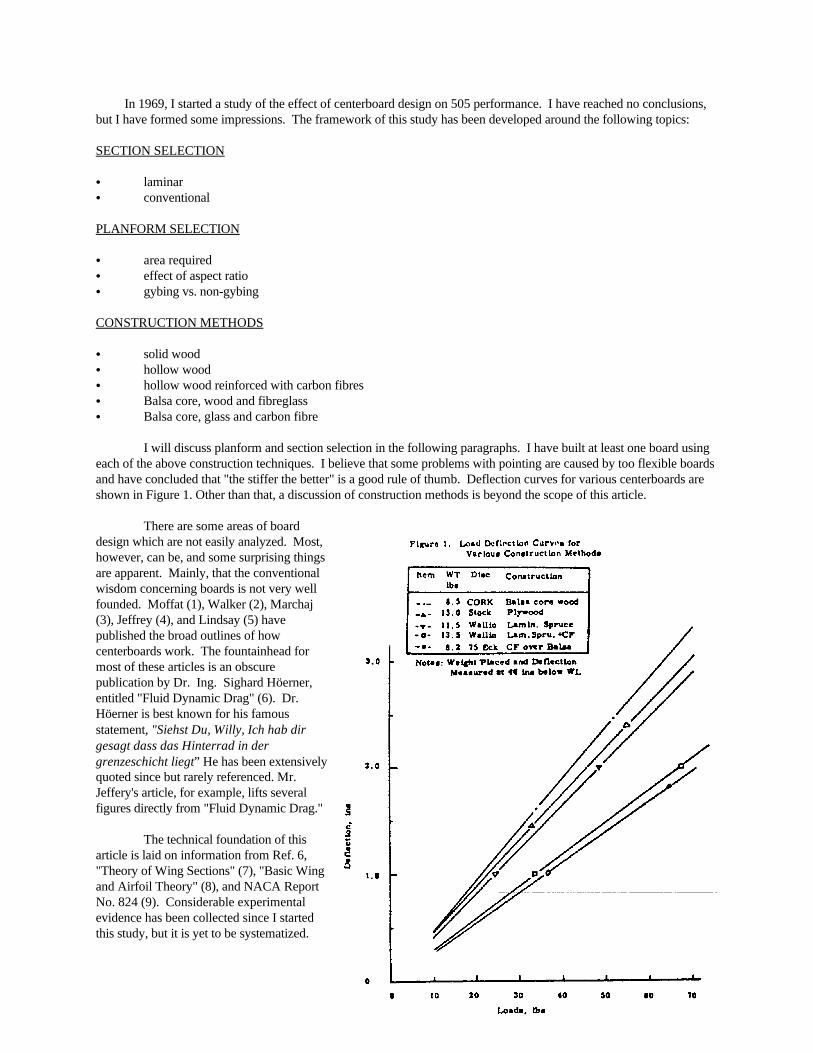
I will discuss planform and section selection in the following paragraphs. I have built at least one board usingeach of the above construction techniques. I believe that some problems with pointing are caused by too flexible boardsand have concluded that "the stiffer the better" is a good rule of thumb. Deflection curves for various centerboards areshown in Figure 1. Other than that, a discussion of construction methods is beyond the scope of this article.
There are some areas of boarddesign which are not easily analyzed. Most,however, can be, and some surprising thingsare apparent. Mainly, that the conventionalwisdom concerning boards is not very wellfounded. Moffat (1), Walker (2), Marchaj(3), Jeffrey (4), and Lindsay (5) havepublished the broad outlines of howcenterboards work. The fountainhead formost of these articles is an obscurepublication by Dr. Ing. Sighard Höerner,entitled "Fluid Dynamic Drag" (6). Dr.Höerner is best known for his famousstatement, "Siehst Du, Willy, Ich hab dirgesagt dass das Hinterrad in dergrenzeschicht liegt” He has been extensivelyquoted since but rarely referenced. Mr. Jeffery's article, for example, lifts severalfigures directly from "Fluid Dynamic Drag."
The technical foundation of thisarticle is laid on information from Ref. 6,"Theory of Wing Sections" (7), "Basic Wingand Airfoil Theory" (8), and NACA ReportNo. 824 (9). Considerable experimentalevidence has been collected since I startedthis study, but it is yet to be systematized.
SUMMARY
There is a tendency, when designing a board, to concentrate on one area, such as aspect ratio, type of section,planform, area, etc. This tendency should be stifled. All areas are important and each interacts with the other. If thisnotion is held firmly in mind, a near optimum board can be designed with very little grief. Failure to consider the wholewill result in success only by chance.
If you are willing to believe without wading through the analytical development, start building immediatelyafter finishing reading this list. If you are skeptical, press on.
(1) 505 fins are too heavily loaded to use laminar sections. Stick to the NACA 00-series for best performance.Make the root thickness as great as will f it in the trunk (~1.3 inches ) and hold the thickness constant until about 2/3down the span. Start holding a constant percent-of-chord thickness from 2/3 to the tip.
(2) Average 505 crew size requires a side force lift of about 160 pounds to be developed by the centerboard.
(3) Lift coefficient (Cl) of ~0.43 is required by 505s if the board is held around 650 in . This looks like the best2
area for general use. Specialized boards may have advantages but can be treacherous if wind speed changes suddenly. They are not recommended.
(4) The board should gybe reliably and be mechanically stiff. Maximum attainable gybe angle is 4.3 using myconstruction methods. This gybe angle leads to Cl ~0.45.
(5) Lower area than ~600 in results in higher board angles of attack (leeway) than can be accommodated by2
reasonable qybe angles. They may also cause sail sheeting angle problems which may be mistaken for "overgybing"boards.
(6) Maximum span which can be fit into a trunk should be used. Root chord and planform should be chosen toprovide 600 - 650 in area using maximum span.2
(7) A tip chord to root chord ratio of 0.34 to 0.40 should be used to minimize induced drag due to lift. Leading edgeaft sweep of 5 also tends to minimize drag. Square tips are preferred. Höerner tips require loss of span to get intonormal trunk. Otherwise, they have a theoretical advantage.
(8) High aspect ratio boards are not prone to stall per se. However, heavily loaded boards are prone to stall. Ifaspect ratio is increased by decreasing area without changing span, no decrease in induced drag will occur. This iscontrary to the implications of a statement by Peter Barret in "Yacht Racing." Barret wasn't necessarily wrong, justsloppy in his use of how high aspect ratio is obtained with respect to span loading.
(9) Alleged effects of deeper than standard boards on stability are not necessarily founded in fact. See Figure 11 forincreased crew weight required.
Before pressing on, let me warn you that this article is written for those who have a basic understanding of fluiddynamics. If I back off too far into explaining fluids, the thrust of what I'm trying to do will be lost. Similarly, if Ioversimplify I will be only covering ground which has been heavily trod by others. If you can do algebra and take thetime to read the references, you won't have a problem. If you are already a fluids specialist, you will wonder why Iexplain so many obvious points. So, let's all be tolerant and define our terms.
GLOSSARY
o Angle of attack uncorrected for finite aspect ratio, degrees.
g Angle of attack corrected for finite aspect ratio, degrees.

V 2
2g
Cl Lift coefficient, dimensionless.
Clo Lift coefficient for two dimensional flow, dimensionless.
Cd Drag coefficient, dimensionless.
Cdo Drag coefficient- for two dimensional flow, dimensionless.
Profile Drag, DoDrag generated by pulling the board through the water at zero angle of attack, lbs. Mathematically;(Cdo)(area)(dynamic head).
Induced Drag, DiDrag induced as a concomitant to lift generation (lbs.). Induced drag is only a function of span loading. Contrary to popular misconception, induced drag cannot be decreased by increasing aspect ratio if span is notincreased. Mathematically: (Cdi)(area)(dynamic head).
Drag, DDrag generated by pulling the board through the water at some angle of attack, lbs. Mathematically: (Cd) (area)(dynamic head) D = Do + Di, in general.
Lift, LThe side force generated by pulling the board through the water at some angle of attack, lbs. Mathematically:(Cl)(area)(dynamic head).
ReReynolds number. A dimensionless scaling parameter used to predict full scale results from model tests (purists,forgive me). Mathematically: the ratio of dynamic to viscous forces.
Dynamic Head
Mathematically: or, for fresh water, 0.98V .2
where: V = Velocity of the fin through the water, ft/sec.
Span, The depth of the tip of the board below the hull, ft.
ChordThe width of the board in the direction flow, ft.
Root ChordThe chord at the first spanwise station after the board emerges from the hull,
Thickness, tThe thickness of the board perpendicular to the direction of flow, inches.
PlanformSide view of the board.
ProfileThe fore and aft cross-section of the planform (also referred to as “section”).
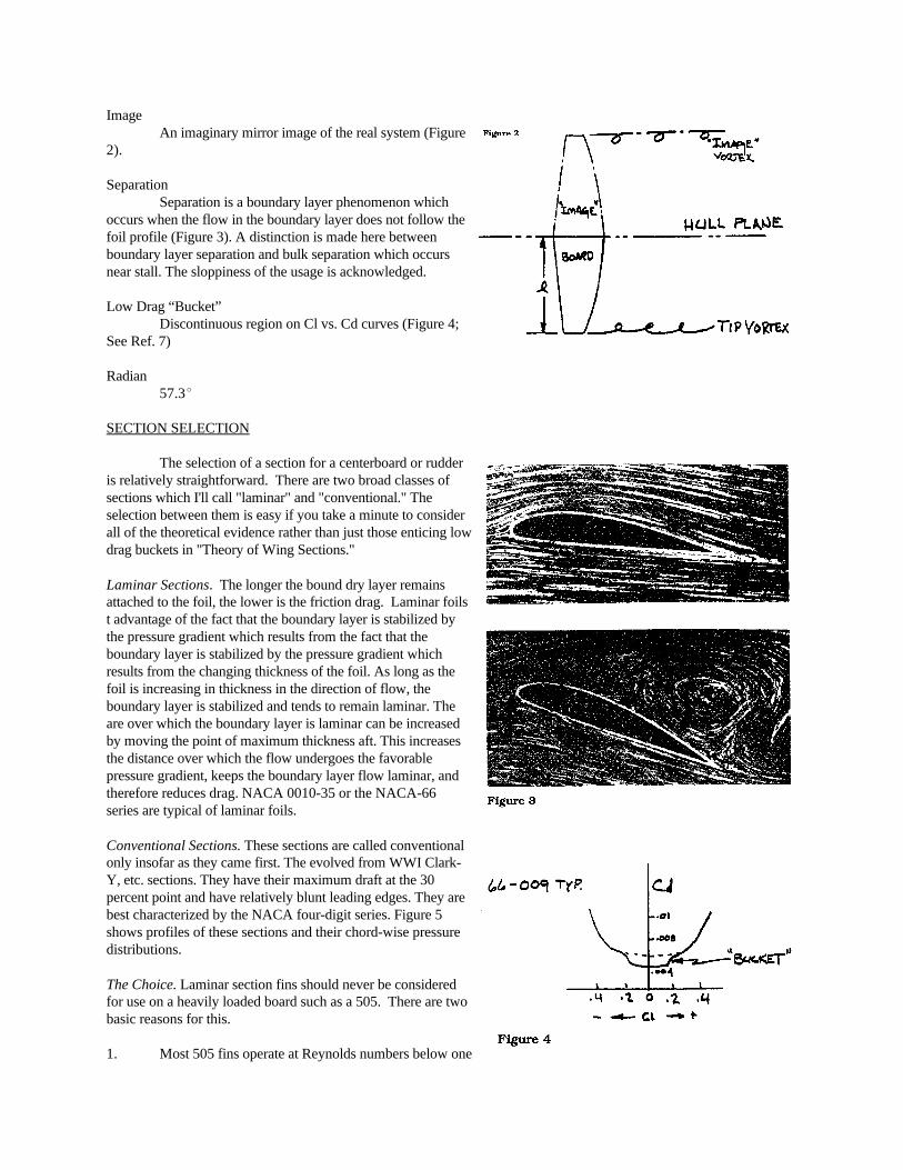
ImageAn imaginary mirror image of the real system (Figure
2).
SeparationSeparation is a boundary layer phenomenon which
occurs when the flow in the boundary layer does not follow thefoil profile (Figure 3). A distinction is made here betweenboundary layer separation and bulk separation which occursnear stall. The sloppiness of the usage is acknowledged.
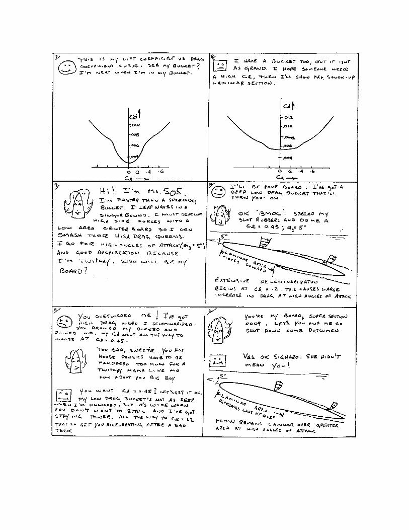
Low Drag “Bucket”Discontinuous region on Cl vs. Cd curves (Figure 4;
See Ref. 7)
Radian57.3
SECTION SELECTION
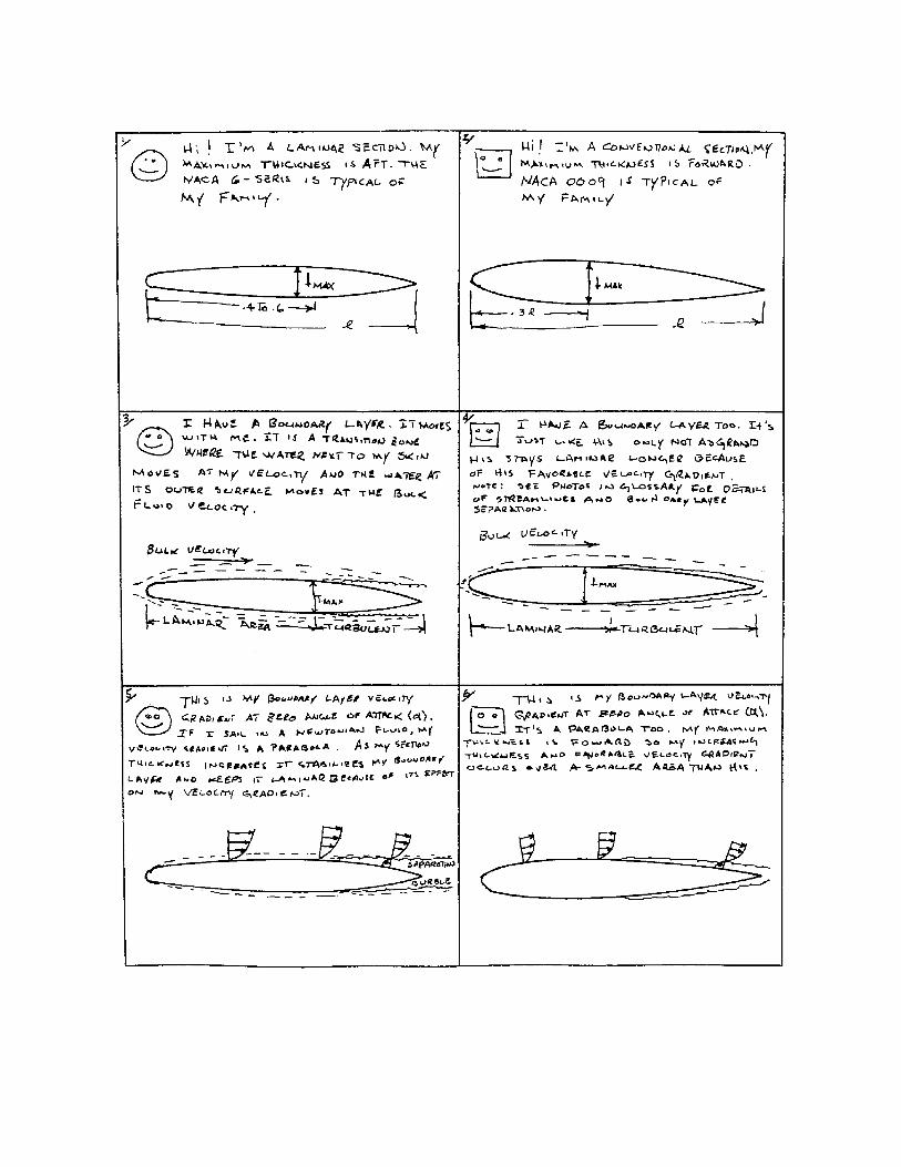
The selection of a section for a centerboard or rudderis relatively straightforward. There are two broad classes ofsections which I'll call "laminar" and "conventional." Theselection between them is easy if you take a minute to considerall of the theoretical evidence rather than just those enticing lowdrag buckets in "Theory of Wing Sections."
Laminar Sections. The longer the bound dry layer remainsattached to the foil, the lower is the friction drag. Laminar foilst advantage of the fact that the boundary layer is stabilized bythe pressure gradient which results from the fact that theboundary layer is stabilized by the pressure gradient whichresults from the changing thickness of the foil. As long as thefoil is increasing in thickness in the direction of flow, theboundary layer is stabilized and tends to remain laminar. Theare over which the boundary layer is laminar can be increasedby moving the point of maximum thickness aft. This increasesthe distance over which the flow undergoes the favorablepressure gradient, keeps the boundary layer flow laminar, andtherefore reduces drag. NACA 0010-35 or the NACA-66series are typical of laminar foils.
Conventional Sections. These sections are called conventionalonly insofar as they came first. The evolved from WWI Clark-Y, etc. sections. They have their maximum draft at the 30percent point and have relatively blunt leading edges. They arebest characterized by the NACA four-digit series. Figure 5shows profiles of these sections and their chord-wise pressuredistributions.
The Choice. Laminar section fins should never be consideredfor use on a heavily loaded board such as a 505. There are twobasic reasons for this.
1. Most 505 fins operate at Reynolds numbers below one

See also NACA TN. No. 1591, Ref. 101
million.
2. The design lift coefficient for a 505 centerboard is inexcess of 0.35 (see following section on planforms). Laminarsection low drag buckets are rarely more than + .15 wide. Thisrequires operation outside of the low drag region and results inhigher than conventional foil drag.
The effects of the first of these facts are somewhatobscure, so I will just quote from NACA No. 824:
“…The effect on minimum drag of the position ofminimum pressure which determines the extent of laminar flowis shown for some NACA 6-series airfoils. The data show aregular decrease in drag coefficient with rearward movementsof minimum pressure( maximum thickness, Ed.)... It may benoted that the drag coefficient for the NACA 65-418 airfoil atlow Reynolds numbers is substantially higher (emphasis mine)than for the NACA 0012, whereas, at high Reynolds numbers,the opposite is the case. The higher drag of the NACA 65-418airfoil section at low Reynolds numbers is caused by arelatively extensive region of laminar separation downstream ofthe point of minimum pressure. This region decreases in size with increasing Reynolds numbers.”
There are several other references which note this low Reynolds number behavior. But the gist of it isplain. Extensive separation occurs because of the high trailing edge angle which exists when the maximumthickness point is moved aft. The streamlines do not follow the profile of the fin because the sides areconverging too rapidly. Therefore, this produces a “separation burble” which grows with decreasingReynolds number and causes increased drag. The lower trailing edge angles of the conventional sectionsresult in lower drag at Reynolds numbers below about 1.1 million. The onset of this effect can be observed inthe curves in “Theory of Wing Sections.” Note how Cd increases with decreasing Reynolds number at Cl=0.4for the 001035 and 6-series sections. Note how little change there is under these conditions with the 00091
section. Reynolds number of one million and lift coefficients of 0.4 are typical values for a 505, as will beshown.
The second reason for not using a "laminar" section is that the low drag bucket characteristic of thesesections never extends to lift coefficients of the order required for a standard 505 board. It may be possibleto build an extremely large board (approximately 8 square feet) and achieve a design lift coefficient whichwould be in the low drag bucket (such a lightly loaded board might indeed be laminar, but remember that thedrag coefficient must be multiplied by the planform area when calculating the drag, and this will always resultin increased drag for the conditions under which 505 foils operate. See figure 10 for effects of area on drag.)
The profile drag coefficients (Cdo) for various sections at the design lift coefficients studied in the nextchapter are shown in Table 1.

Data from Reference 9 for two dimensional flow (infinite aspect ratio) sections at a Reynolds number of three million.2
The area implied in Cl of .2845 increasing to .4580 is 61%. Note that for all cases, the increase in Cd is less than 61%.3
Therefore it will always pay to decrease area if all other variables are constant. This is borne out in Figure 10.
Note that for all cases examined, the 00-series sections are superior.4
Table 12
Comparison of Various Lift and Drag Coefficients for Various Symmetrical Sections of Infinite Aspect Ratio
Section Cl Cd % increase in % increase in Width of Low % Cl Beyond3
Cd Cd Drag Bucket low drag region4
0009 0.2845 0.0058 — — ±0.25 114
0010-35 0.2845 0.0065 12.1 12. 1 ±0.12 237
64-0009 0.2845 0.0060 3.4 3.4 ±0.15 190
66-0009 0.2845 0.0068 17.2 17.2 ±0.10 285
0009 0.3438 0.0060 — 3.5 ±0.25 138
0010-35 0.3438 0.0068 13.3 17.2 ±0.12 287
64-0009 0.3438 0.0070 16.7 20.7 ±0.15 229
66-0009 0.3438 0.0070 16.7 20.7 ±0.10 344
0009 0.3919 0.0061 — 5.2 ±0.25 157
0010-35 0.3919 0.0071 16.4 22.4 ±0.12 327
64-0009 0.3919 0.0075 23.0 29.3 ±0.15 261
66-0009 0.3919 0.0072 18.0 24.1 ±0.10 392
0009 0.4580 0.0065 — 12.1 ±0.25 183
0010-35 0.4580 0.0080 23.1 37.9 ±0.12 382
64-0009 0.4580 0.0078 20.0 34.5 ±0.15 305
66-0009 0.4580 0.0075 15.4 29.3 ±0.10 458
These data are for Reynolds numbers equal to 3 million. Operating Reynolds number for a 50 board at hullspeed will vary from 0.9 to 1.4 million, depending on planform selection. This reduced Reynolds number willaccentuate the shortcomings of the laminar section for use a 505. Careful study of Table 1 shows thatconventional sections are optimum over a much wider range of lift coefficients than are laminar sections.
Under no circumstances do laminar sections offer an advantage, and under low Reynolds number and/or highloading conditions they may offer a significant disadvantage.
Spanwise Thickness Distribution. After selecting the NACA 00-series section, we must decide whatthickness distribution to use al the board span. The centerboard slot width (35 mm - 1.40 ins.) limits theboard thickness and the root chord section; therefore, become dependent on the choice of root chord length. Maximum root chord section for a 17 inch root chord board is 8.1 percent. Similarly, a 14 inch root chordboard could use a 10 percent root section. It is best to use a board that fills the trunk. Thinner boards twistmore and boards of lower thickness-to-chord ratio stall easier.
There is a theoretical advantage in holding the percent section constant, or decreasinq it, as the spanincreases toward the tip. I believe this advantage is difficult to realize in practice. Wings are usuallycambered and given "wash" to account for structural twist under load. A centerboard must be a symmetricalsection and wash and camber are not viable solutions. Thin, highly loaded, high angle of attack (caused bytwist) board tips are very prone to stall, especially at low speed in choppy waters. Therefore, I recommendusing a constant thickness (variable sections, to about 2/3 of the board span. The maximum section thicknessI use in a board is 10.8 percent. I use 12-14 percent sections in rudders.
PLANFORM SELECTION
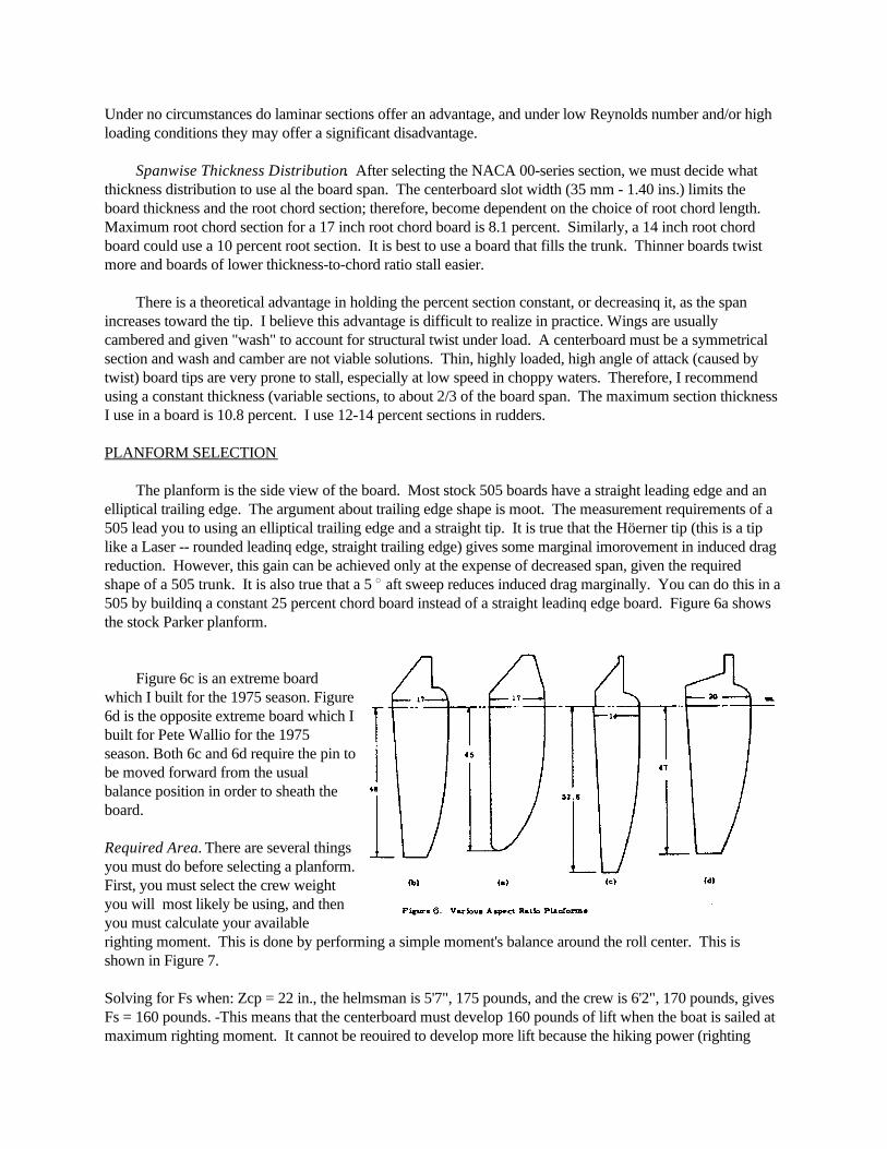
The planform is the side view of the board. Most stock 505 boards have a straight leading edge and anelliptical trailing edge. The argument about trailing edge shape is moot. The measurement requirements of a505 lead you to using an elliptical trailing edge and a straight tip. It is true that the Höerner tip (this is a tiplike a Laser -- rounded leadinq edge, straight trailing edge) gives some marginal imorovement in induced dragreduction. However, this gain can be achieved only at the expense of decreased span, given the requiredshape of a 505 trunk. It is also true that a 5 aft sweep reduces induced drag marginally. You can do this in a505 by buildinq a constant 25 percent chord board instead of a straight leadinq edge board. Figure 6a showsthe stock Parker planform.
Figure 6c is an extreme boardwhich I built for the 1975 season. Figure6d is the opposite extreme board which Ibuilt for Pete Wallio for the 1975season. Both 6c and 6d require the pin tobe moved forward from the usualbalance position in order to sheath theboard.
Required Area. There are several thingsyou must do before selecting a planform.First, you must select the crew weightyou will most likely be using, and thenyou must calculate your availablerighting moment. This is done by performing a simple moment's balance around the roll center. This isshown in Figure 7.
Solving for Fs when: Zcp = 22 in., the helmsman is 5'7", 175 pounds, and the crew is 6'2", 170 pounds, givesFs = 160 pounds. -This means that the centerboard must develop 160 pounds of lift when the boat is sailed atmaximum righting moment. It cannot be reouired to develop more lift because the hiking power (righting
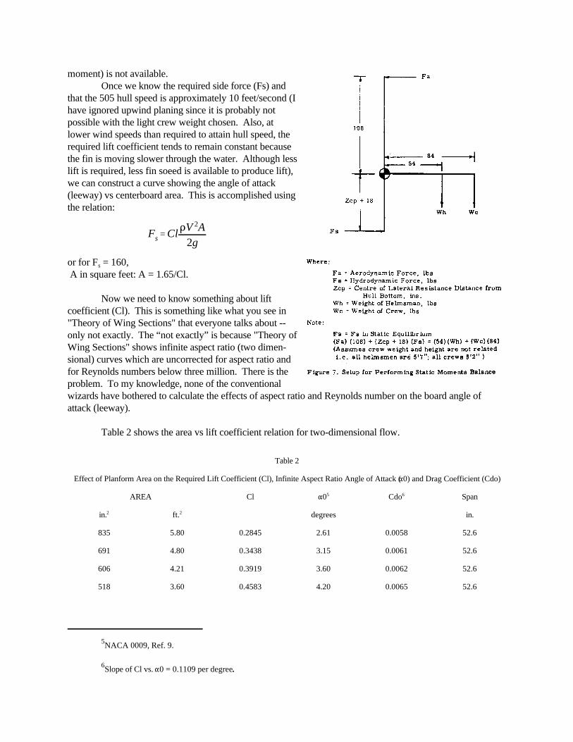
Fs Cl V 2A2g
NACA 0009, Ref. 9.5
Slope of Cl vs. 0 = 0.1109 per degree.6
moment) is not available.Once we know the required side force (Fs) and
that the 505 hull speed is approximately 10 feet/second (Ihave ignored upwind planing since it is probably notpossible with the light crew weight chosen. Also, atlower wind speeds than required to attain hull speed, therequired lift coefficient tends to remain constant becausethe fin is moving slower through the water. Although lesslift is required, less fin soeed is available to produce lift),we can construct a curve showing the angle of attack(leeway) vs centerboard area. This is accomplished usingthe relation:
or for F = 160,s
A in square feet: A = 1.65/Cl.
Now we need to know something about liftcoefficient (Cl). This is something like what you see in"Theory of Wing Sections" that everyone talks about --only not exactly. The “not exactly” is because "Theory ofWing Sections" shows infinite aspect ratio (two dimen-sional) curves which are uncorrected for aspect ratio andfor Reynolds numbers below three million. There is theproblem. To my knowledge, none of the conventionalwizards have bothered to calculate the effects of aspect ratio and Reynolds number on the board angle ofattack (leeway).
Table 2 shows the area vs lift coefficient relation for two-dimensional flow.
Table 2
Effect of Planform Area on the Required Lift Coefficient (Cl), Infinite Aspect Ratio Angle of Attack ( 0) and Drag Coefficient (Cdo)
AREA Cl 0 Cdo Span5 6
in. ft. degrees in.2 2
835 5.80 0.2845 2.61 0.0058 52.6
691 4.80 0.3438 3.15 0.0061 52.6
606 4.21 0.3919 3.60 0.0062 52.6
518 3.60 0.4583 4.20 0.0065 52.6

Before we go on with area selection, it is first necessary to introduce the concept of aspect ratio andshow how it modifies the two-dimensional results shown in Table 2.
Aspect RatioThere is a pressure difference between the mass of fluid on either side of a foil generating lift. This
pressure difference is a driving force for fluid on one side of the foil to flow to the other side. The greater thespan, the less influence the flow at the tip will have on the flow at the root, and the more nearly two-dimensional the flow will be over the majority of the foil. Even though the details are as Jeffery indicates, ifyou think of the flow rolling up into a tip vortex to satisfy the pressure discontinuity at the foil tip, you won’tgo too far wrong. Now, if you think of a tip vortex as a loss (drag), there is only one further conceptualizationnecessary; i.e., the greater the distance of the tip vortex from its image, the lower the drag due to the tipvortex. (“Image” is an imaginary vortex which exists at the other end of the symmetrical "wing” system. (Seesketch in glossary.)
Aspect ratio provides a means of determining how much the theoretical two-dimensional drag due tolift (induced drag) is increased by the spanwise flow component which exists in real-world three-dimensionalflow. The concept of "span loading" is somewhat easier to follow in assessing this loss in that this axiomstates that induced drag is only a function of span and not aspect ratio if the physical lift force on thecenterboard is held constant. Or, stated another way, induced drag can only be reduced by increasing span,not by decreasing chord while holding span constant, as would be implied if it were truly a function of aspectratio.
The calculation of aspect ratio for a centerboard is different from a rudder because the hull offers anend plate effect (axis of symmetry) which is not available to a rudder. I use a 1.7 "image" for calculatingcenterboards and 1.0 for rudders.
AR = 1.7 /Area; Ar = l.0 /Area2 2r
From a practical standpoint, one needs to know only two relations to determine the effect of aspectratio (or span loading) on drag and leeway angle. These are:
g = + Cl/ AR0
Cd = Cdo + Cl / AR2
where:
Cdo = two dimensional drag coefficient at design Cl (from curves)
o = two dimensional angle of attack at design Cl (from curves) (note angles in radians)
g = geometric angle of attack (leeway)
D Cd V 2
2g
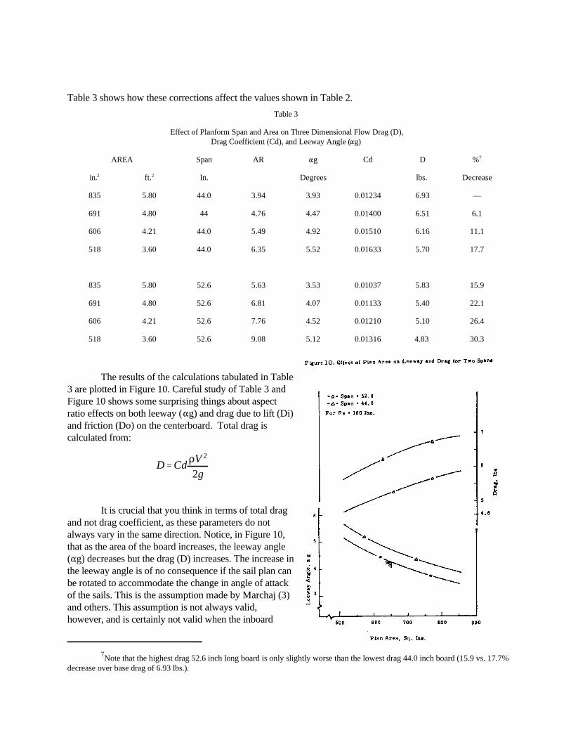
Note that the highest drag 52.6 inch long board is only slightly worse than the lowest drag 44.0 inch board (15.9 vs. 17.7%7
decrease over base drag of 6.93 lbs.).
Table 3 shows how these corrections affect the values shown in Table 2.Table 3
Effect of Planform Span and Area on Three Dimensional Flow Drag (D),Drag Coefficient (Cd), and Leeway Angle ( g)
AREA Span AR g Cd D %7
in. ft. In. Degrees lbs. Decrease2 2
835 5.80 44.0 3.94 3.93 0.01234 6.93 —
691 4.80 44 4.76 4.47 0.01400 6.51 6.1
606 4.21 44.0 5.49 4.92 0.01510 6.16 11.1
518 3.60 44.0 6.35 5.52 0.01633 5.70 17.7
835 5.80 52.6 5.63 3.53 0.01037 5.83 15.9
691 4.80 52.6 6.81 4.07 0.01133 5.40 22.1
606 4.21 52.6 7.76 4.52 0.01210 5.10 26.4
518 3.60 52.6 9.08 5.12 0.01316 4.83 30.3
The results of the calculations tabulated in Table3 are plotted in Figure 10. Careful study of Table 3 andFigure 10 shows some surprising things about aspectratio effects on both leeway ( g) and drag due to lift (Di)and friction (Do) on the centerboard. Total drag iscalculated from:
It is crucial that you think in terms of total dragand not drag coefficient, as these parameters do notalways vary in the same direction. Notice, in Figure 10,that as the area of the board increases, the leeway angle( g) decreases but the drag (D) increases. The increase inthe leeway angle is of no consequence if the sail plan canbe rotated to accommodate the change in angle of attackof the sails. This is the assumption made by Marchaj (3)and others. This assumption is not always valid,however, and is certainly not valid when the inboard

sheeting limitations of a 505 are considered. Second, notice that the same area boards having a span of 44inches (this implies a wider root chord) insstead of 52.6 inches, suffer even greater losses in leeway angle anddrag. These boards all generate a lift of 160 pounds. Marchaj (3) and others have shown that the lift to dragratio is the cotangent of the pointing angle. Therefore, the change in pointing angle which occurs within the52.6 span series is 0.40 and the variation between the best 52.6 span board (AR = 9.08) and the worst 44inch span board (AR = 3.94) is 0.70. This result is true even if the effects of increased leeway on sail planangle of attack are ignored.
The beneficial effects of greater span are seen to have sound theoretical basis. There is, however, anargument which states that long span boards make the boat harder to hold down. This is supposedly becausethe deeper center of pressure of the high span board generates a higher roll moment for a given amount of lift. Referring back to Figure 7, it is now apparent why I left the term Zcp as a variable in the moments diagram. By substituting varying Zcp (distance to center of pressure ) into this moments diagram, one can construct acurve showing the crew weight change requiredto keep the boat on its bottom. Figure 11 showsa plot of the results of this exercise. As you cansee, the practical effects of span changes are notgreat.
It is true that people have problems withlong boards in heavy air. I believe this has to dowith a yaw couple which is set up when the boatis allowed to heel. If you sail it flat and don't getout of shape, a long board should not have asignificant effect on heavy air stability. If you doget out of shape, the chances are that the yawcouple will lead to a broach -- fast. The longerthe board, the greater the demands on thehelmsman for quick and accurate steering.
We have seen that, for any board area underconstant loading, increased span will improvepointing by decreasing drag; but we still have notselected board area. This selection will be madeon a less than scientific basis; so first, we have todecide on whether or not we want to gybe theboard.
Gybing vs. Non-Gybing. The board should gybe. But, it must be strong enough to prevent twist and thegybing strips and section thickness must be arranged to prevent negative gybing on the reaches.
A gybing board does two things:
It decreases hull form drag by allowing the hull to track straight through the water instead ofcrabbing at the leeway angle.
It allows the jib tack to be rotated more to leeward of the apparent wind for a given leeway angle, jibfairlead and boom position.
The effect of the second item above may be more important than the first. By allowing the sail plan
to rotate to leeward by the amount of the gybe angle, the effective sheeting angle is increased and better drivecan be obtained for the same course made good. Looked at another way, a gybing board allows the relativejib fairlead position to move inboard by the amount of the gybe angle. This is good for those occasions whenpointing is everything and you want extreme inboard sheeting, but don't want those crew-destroyingcontraptions otherwise required to get extreme inboard sheeting. Anything that can be gained by greaterinboard sheeting is good for pointing. It is not true, however, that the pointing angle is decreased by the gybeangle. Only what improvement in the sail. lift to drag ratio that can be effected by the altered sheeting anglewill improve the pointing angle.
I recognize that the positive "it should gybe" statement will draw some negative response. Inferencearguments will be made that there is no experimental evidence to show that gybing will help. While this maybe true of observations made by some, it is not true of all (Cf. Bram Dally). The real problem is that veryfew boards (except mine) are specifically designed to gybe the amount of the leeway angle. Using theproposed method for area selection, it is seen that it will be impossible to overgybe the board although it willstill be possible to oversheet the jib. Unless the board gybes the amount of the leeway angle, it is unlikelythat any change in performance will be noted experimentally. Considering the haphazard manner in whichgybe angles are usually selected, it is not surprising that the potential advantages of gybing boards have notbeen realized.
Now the selection of the board area can be made. I have been unable to build a reliable board with agreater than 4.3 gybe angle. If you can build one ... GOOD! Pick the area such that, with your rightingmoment and maximum side force, your leeway angle will be 4.3 (or however great you can make your gybeangle). See, I told you it wasn't going to be scientific. This is best done by constructing a curve like Figure10 for the side force (Fs) you can develop with your maximum righting moment and determining the areawhich gives you a leeway angle equal to your gybe angle.
RECOMMENDATIONS
(1) A 505 board tip should be at least 48 inches below the hull.
(2) The area should be between 600 and 700 square inches.
(3) The gybe angle should be 4 (or however great you can reliably build it except never more than theleeway angle). Area should be selected by interaction of gybe angle (leeway) with curve of Figure 10type for your Fs.
(4) Once you select your area, use the highest aspect ratio (longest length) possible. Note that the spaninteracts with the area when entering Figure 10 type curve with gybe angle (leeway).
If you follow these recommendations, win the start and cover the fleet, you will do very well.
REFERENCES
1. Moffatt, George, "Centerboard and Rudder Design," One Design and Offshore Yachtsman, Vol. 8,No. 4, April 1969.
2. Walker, Stuart (Editor), "Performance Advances in Small Boat Racing, W. W. Norton & Co., Inc.,New York, 1969.

3. Marchaj, C. A., "Sailing Theory and Practice," Dodd, Mead & Co., New York, 1964.
4. Jeffery, C.B., "Boards and Rudders - A Scientific View," Yacht Racing, Vol. 13, No. 4, April 1974.
5. Lindsay, Mark, "High Lift Hydrodynamics," Yacht Racing, Vol. 13, No. 3, March 1974.
6. Höerner, Sighard, "Fluid Dynamic Drag," Published by the author, Midland Park, N. J., 1958.
7. Abbott, Ira and Albert E. Von Dorenhoff, "Theory of Wing Sections," Dover Publications, Inc., NewYork, 1959.
8. Pope, Alan, "Basic Wing and Airfoil Theory," McGraw-Hill Book Company, Inc., New York, N.Y.,1951.
9. Abbott, Ira, Albert E. Von Dorenhoff and Louis Stivers, Jr., "Summary of Airfoil Data," Report No.824, Thirty First Annual Report of the National Advisory Committee for Aeronautics , United StatesGovernment Printing Office, Washington, D.C. 1949.
10. Loftin, Laurence K.,Jr. and Kenneth S. Cohen, "Aerodynamic Characteristics of a Number ofModified NACA Four-Digit-Series Airfoil Sections," NACA Technical Note No. 1591, June 1948.