Embed Size (px)
Citation preview

ASSEMBLY, OPERATION & MAINTENANCE
INSTRUCTION MANUAL
TRAMCO
MODEL GTM, MODEL RBTM, & BULK-FLOTM
EN-MASSE CHAIN CONVEYORS
Failure to follow instructions and safety precautions can result in serious injury, death, or property damage. Keep manual for future reference. November 2011
Read this manual before using any En-Masse chain conveyor purchased from Tramco, Inc. Revised

Tramco, Inc. – Drag Conveyor All Models
2
This product has been designed and constructed according to general engineering standardsa. Other local regulations may apply and must be followed by the operator. For this reason, we strongly recommend that all personnel associated with this equipment be trained in the correct operational and safety procedures required for this product. Periodic reviews of this manual with all employees should be standard practice. For your convenience, we include this sign-off sheet so you can record your periodic reviews.
Date Employee Signature Employer Signature
a. Standards could include organizations such as the American Society of Agricultural and Biological Engineers, American National Standards Institute, Conveyor Equipment Manufacturers’ Association.
Tramco, Inc. / 1020 East 19th Street / Wichita, KS 67214 / (316) 264-4604/ www.tramcoinc.com
Tramco, Inc. – Drag Conveyor All Models
3
Table of Contents 1. Introduction..................................................................................................................4 2. Safety First.............................................................................................................. 6-13
2.1. General Safety: .......................................................................................................8 2.2. Assembly Safety: ....................................................................................................9 2.3. Operational & Maintenance Safety: ............................................................…10-11
2.3.1. Lockout and Tagout Procedures: ...........................................................…11 2.4. Safety Decal Locations: ....................................................................................…12
2.4.1. Decal Installation: ..................................................................................…12 2.4.2. Decal Content and Locations: ................................................................…13
3. On Site Assembly ................................................................................................. 14-42
3.1. Lifting and Moving:..............................................................................................14 3.2. Tramco MODEL GTM:..........................................................................................15
3.2.1. Head Discharge Section with Drive Shaft: ................................................16 3.2.2. Tail Section with Take-up Assembly:........................................................16 3.2.3. Intermediate Trough Section: ....................................................................17 3.2.4. Rino Seals: .................................................................................................18 3.2.5. Conveyor Chain & Flights: ........................................................................19 3.2.6. Assembly Bolts & Alignment pins: ...........................................................20 3.2.7. Additional Take-up Option: .......................................................................21
3.3. Tramco MODEL RBTM: ......................................................................................22 3.3.1. Head Discharge Section with Drive Shaft: ................................................23 3.3.2. Tail Section with Take-up Assembly:........................................................23 3.3.3. Intermediate Trough Section: ....................................................................24 3.3.4. Seals: ..........................................................................................................25 3.3.5. Conveyor Chain & Flights: ........................................................................26 3.3.6. Assembly Bolts & Alignment pins: ...........................................................27
3.4. Tramco BULK-FLOTM: ........................................................................................28 3.4.1. Head Discharge Section with Drive Shaft: ................................................29 3.4.2. Tail Section with Take-up Assembly:........................................................29 3.4.3. Intermediate Trough Section: ....................................................................30 3.4.4. Rino Seals: .................................................................................................31 3.4.5. Conveyor Chain & Fights: .........................................................................32 3.4.6. Assembly Bolts & Alignment pins: ...........................................................33 3.4.7. Additional Take-up Option: .......................................................................34
3.5. General Arragement Drawings: ...................................................................... 35-40 3.6. General Assembly Instructions:...................................................................... 41-43
3.6.1. Chain Assembly Instructions: .............................................................. 44-47 3.7. Component Information: ................................................................................ 48-49
Tramco, Inc. / 1020 East 19th Street / Wichita, KS 67214 / (316) 264-4604/ www.tramcoinc.com

Tramco, Inc. – Drag Conveyor All Models
4
Table of Contents, cont’d
4. Operation.............................................................................................................. 50-51
4.1. Pre-Operation Checklist: ......................................................................................50 4.2. Start-Up: ......................................................................................................... 50-51 4.3. General:.................................................................................................................51 4.4. Extended Shutdown/Storage:................................................................................51
5. Maintenance ......................................................................................................... 52-54
5.1. Pre-Operation Checklist: ......................................................................................53 5.2. Sprockets: ....................................................................................................... 53-54
6. Troubleshooting ................................................................................................... 55-56 7. Terms and Conditions of Sale............................................................................. 57-60
Tramco, Inc. / 1020 East 19th Street / Wichita, KS 67214 / (316) 264-4604/ www.tramcoinc.com

Tramco, Inc. – Drag Conveyor All Models
5
1. INTRODUCTION Tramco, Inc. En Masse Chain-Flight Conveyors are tough, dependable, and provide efficient handling capacity for conveying a wide variety of bulk materials with minimum product degradation. The flat & round bottom designs increase conveying capacity, and special Tramco, Inc. features substantially reduce the product-to-product contamination that you find with other designs. Product features include:
Rugged, heavy-duty steel construction for durability in the most demanding applications.
Dust and weather-tight construction to maintain product quality against the elements and prevent dust from escaping.
UHMW polyethylene flights to reduce metal-to-metal contact and provide quiet, efficient operation.
Replaceable bottoms and side liners. Head and tail are equipped with removable covers to facilitate maintenance.
Before using the Drag Conveyor, give this manual to the people who will be assembling, operating and maintaining this equipment. Reading and understanding the manual will reduce downtime and equipment failure, as well as help to ensure safe and efficient operation. A sign-off form is provided on the inside front cover for your convenience. The serial number plates are located on the head assembly and on the tail assembly. Please mark the number in the space provided for easy reference.
Model # Serial # Production Year
Tramco, Inc. / 1020 East 19th Street / Wichita, KS 67214 / (316) 264-4604/ www.tramcoinc.com
Tramco, Inc. – Drag Conveyor All Models
6
2. SAFETY FIRST
The Safety Alert symbol identifies important safety messages on the product and in the manual. When you see this symbol, be alert to the possibility of personal injury or death. Follow the instructions in the safety messages. Why is SAFETY important to you? Three big reasons:
1. Accidents disable and kill. 2. Accidents cost. 3. Accidents can be avoided.
SIGNAL WORDS The Safety Alert symbol, pictured above, means ATTENTION, BE ALERT, YOUR SAFETY IS INVOLVED.
Note: The use of the signal words DANGER, WARNING, CAUTION, and NOTICE are used in conjunction with the safety messages. The appropriate signal word for each message has been selected using safety as a guideline.
Tramco, Inc. / 1020 East 19th Street / Wichita, KS 67214 / (316) 264-4604/ www.tramcoinc.com

Tramco, Inc. – Drag Conveyor All Models
7
2. SAFETY FIRST cont’d
DANGER
DEFINITION: Indicates hazardous situation that, if not avoided, will result in serious injury or death.
WARNING
DEFINITION: Indicates a hazardous situation that, if not avoided, could result in serious injury or death.
CAUTION
DEFINITION: Indicates a hazardous situation that, if not avoided, may result in moderate or minor injury.
NOTICE
DEFINITION: Indicates a potentially hazardous situation that, if not avoided, may result in property damage.
YOU are responsible for the SAFE assembly, use and maintenance of your product. YOU must ensure that you and anyone else who is going to work around the product be familiar with all procedures and related SAFETY information contained in this manual. Remember, YOU are the key to safety. Good safety practices not only protect you, but also the people around you. Make these practices a working part of your safety program.
Product owners must give instructions to employees before allowing them to assemble, operate or maintain the product.
The most important safety device on this product is a SAFE user or operator. It is the user/operator's responsibility to read and understand ALL safety instructions in the manual and to follow them. All accidents can be avoided.
A person who has not read and understood all safety instructions is not qualified to assemble, operate or maintain the product. Untrained users/operators expose themselves and bystanders to possible serious injury or death.
Do not modify the product in any way. Unauthorized modification may impair the function and/or safety, and could affect the life of the product.
Any modification to the product voids the warranty. Use this product for its intended purposes only. Think SAFETY! Work SAFELY!
Tramco, Inc. / 1020 East 19th Street / Wichita, KS 67214 / (316) 264-4604/ www.tramcoinc.com

Tramco, Inc. – Drag Conveyor All Models
8
2.1 GENERAL SAFETY Important: The general safety section includes instructions that apply to all safety
practices. Any instructions specific to a certain safety practice (e.g. assembly safety), can be found in the appropriate section.
Read and understand all safety instructions, safety decals, and manual(s) before assembling or operating equipment.
Only trained, competent people shall assemble, operate or maintain the product. An untrained operator is not qualified to operate equipment.
Have a first-aid kit available for use should the need arise, and know how to use it.
Provide a fire extinguisher for use in case of an accident. Store it in a highly visible
place.
Do not allow children, spectators, or bystanders within the work area. Wear appropriate protective gear. This list includes, but is not limited to:
o a hard hat o protective shoes with slip-resistant soles o protective goggles & gloves o hearing protection
For powered products: before maintaining, adjusting, or repairing, unplug and place
all controls in neutral or off position, stop the engine or motor, remove ignition key or lock out power source, and wait for all moving parts to stop.
Review safety information initially and at least annually with all personnel who will be using the product.
Follow good shop practices: o Keep service area clean and dry. o Be sure electrical outlets and tools are properly grounded. o Use adequate light for the job at hand.
Tramco, Inc. / 1020 East 19th Street / Wichita, KS 67214 / (316) 264-4604/ www.tramcoinc.com

Tramco, Inc. – Drag Conveyor All Models
9
2.2 ASSEMBLY SAFETY Have a minimum of 2 people handle the heavy, bulky components. Check all equipment for damage immediately upon arrival. Do not attempt to install a
damaged item. If the equipment must have an open housing as a condition of its use and application,
it must be guarded by a railing or fence. Use rugged gratings where necessary. If the distance between the grating and
moving elements is less than 4 inches, the grating opening must not exceed 1/2” x 1” (or 1/2” x 2” for hopper gratings). Covers, guards, and gratings at inlet points must be installed so that personnel cannot be injured in any way.
o Use solid covers that are designed and installed so that personnel are not exposed to accidental contact with any of the equipment’s moving parts.
o Connect inlet and discharge openings to other equipment in order to completely enclose the equipment.
As required by the applicable laws, standards, and good practice, the purchaser/
owner is responsible for: o guarding all rotating equipment such as drives, gears, shafts, and couplings o purchasing and providing safety devices and controls
Before power is connected to the drive, perform a pre-start-up safety check to ensure the equipment and area is safe and that all guards are in place and secure.
Electrical equipment must conform to the National Electric Code or National
Electrical Safety Code, including requirements for the environment. Also consider:
o Overflow devices (electrical interlocks) to warn personnel and shut off power when discharge from conveyor is interrupted.
o Overload protection for devices (shear pins, torque limiters, etc.) and no speed protection (zero-speed switches) to shut off power in the event of an incident that might cause the conveyor to stop operating.
o Safety shut-off switch with power lockout provisions at conveyor drive. o Emergency stop switches that are readily accessible. o Electrical interlocking to shut down feeding conveyors whenever a receiving
conveyor stops. o Signal devices to warn personnel of imminent start up of conveyor, especially
if started from a remote location.
Tramco, Inc. / 1020 East 19th Street / Wichita, KS 67214 / (316) 264-4604/ www.tramcoinc.com

Tramco, Inc. – Drag Conveyor All Models
10
2.3 OPERATIONAL & MAINTENANCE SAFETY Electrical controls, machinery guards, railings, walkways, arrangement of installation, training of personnel, etc., are necessary for a safe working environment. It is the responsibility of the contractor, installer, owner, and user to supplement the materials and services furnished with the necessary items to make the conveyor installation comply with the law and accepted standards. Do not operate conveyors unless all covers/guards are in place. Advise all operating personnel of the location and operation of all emergency controls
and devices. Maintain clear access to these controls and devices. Do not place hands, feet, or any part of your body or clothing in the conveyor. Never walk on conveyor covers, gratings, or guards. Do not use conveyor for any purpose other than that which it was intended. Do not poke or prod material into the conveyor with a bar or stick inserted through
the openings. Conveyors are not normally manufactured or designed to handle materials that are
hazardous to personnel (explosive, flammable, toxic, or otherwise dangerous materials). However, conveyors may be designed to handle these materials.
Conveyors are not manufactured to comply with local, state, or federal codes for
unfired pressure vessels. For example: If hazardous materials are to be conveyed or if the conveyor is to be subjected to internal or external pressure, consult Tramco, Inc. prior to any modifications.
Be aware of hazardous locations where, without protection, people may be injured by
contact with conveyor or material. If conveyor blocks a walkway, provide a crossover stairway or ramp for passage of personnel. If installed overhead, minimum clearance should be 7 inches for safety.
Handling food subjects conveyors to special codes for construction, location, and
accessibility. Investigate before ordering standard components! Food conveyors often require hinged access doors for drop-bottom trough cleaning,
and such doors require special safety controls and procedures by customer to prevent personal injuries. For example: The extensive use of padlocks, with keys in the hands of only management personnel, is one means frequently used.
Do not attempt a field modification of conveyor or components without first
consulting Tramco, Inc.
Tramco, Inc. / 1020 East 19th Street / Wichita, KS 67214 / (316) 264-4604/ www.tramcoinc.com

Tramco, Inc. – Drag Conveyor All Models
11
2.3 OPERATIONAL & MAINTENANCE SAFETY cont’d Perform frequent inspections of the controls, safety devices, covers, guards, and
equipment to ensure proper working order and correct positioning. The Conveyor Equipment Manufacturer's Association (CEMA) has produced an audio/ visual presentation entitled "Safe Operation of Screw Conveyors, Drag Conveyors, and Bucket Elevators." Tramco, Inc. encourages acquisition and use of this source of safety information. 2.3.1 LOCKOUT AND TAGOUT PROCEDURES To minimize possibility of serious injury or death to workers from hazardous energy release (for example, when restarting the equipment) and to prevent worker deaths from all forms of hazardous energy release, follow all lockout and tagout procedures when installing and maintaining equipment. Ensure that all OSHA procedures are adhered to. For example: De-energize, block, and dissipate all sources of hazardous energy. Lockout and tagout all forms of hazardous energy. Ensure that only 1 key exists for each assigned lock, and that the person who locked
out the equipment, is the only one that holds that key. After verifying all energy sources are de-energized, the service to or installation of
equipment may be performed. Ensure that all personnel are clear before turning on power to equipment. For more information on occupational safety practices, see www.osha.gov.
Tramco, Inc. / 1020 East 19th Street / Wichita, KS 67214 / (316) 264-4604/ www.tramcoinc.com

Tramco, Inc. – Drag Conveyor All Models
12
2.4 SAFETY DECAL LOCATIONS Keep safety decals clean and legible at all times. Replace safety decals that are missing or have become illegible. Replaced parts must display the same decal(s) as the original part. Safety decals are available from your distributor, dealer, or factory. 2.4.1 DECAL INSTALLATION Installation area must be clean and dry, with a temperature above 10°C (50°F). Decide on the exact position before you remove the backing paper. Align the decal over the specified area and carefully press the small portion with the
exposed sticky backing in place. Slowly peel back the remaining paper and carefully smooth the remaining portion of
the decal in place. Small air pockets can be pierced with a pin and smoothed out using the piece of sign
backing paper.
Tramco, Inc. / 1020 East 19th Street / Wichita, KS 67214 / (316) 264-4604/ www.tramcoinc.com

Tramco, Inc. – Drag Conveyor All Models
13
2.4.2 DECAL CONTENT AND LOCATION The types of safety decals and locations on the equipment are shown below. Good safety requires that you familiarize yourself with the various safety decals, the type of warning, and the area or particular function related to that area that requires your SAFETY AWARENESS.
DECAL 1: DECAL 2: DECAL 3: DECAL 4: IOS-CSD-004 ISO-CSD-003 ISO-CSD-008 ISO-CSD-005
Place decal 1 on the head and tail sections. Additional placements of decal 1 may be used and their locations are up to the site supervisor.
Place decal 2 on and behind the belt or chain guard. Place decal 3 on all head, tail, and intermediate section covers, as well as all
inspection and access opening covers. Place decal 4 on the motor conduit boxes.
Tramco, Inc. / 1020 East 19th Street / Wichita, KS 67214 / (316) 264-4604/ www.tramcoinc.com

Tramco, Inc. – Drag Conveyor All Models
14
3. ON SITE ASSEMBLY
WARNING
Before continuing, please re-read the safety information relevant to this section at the beginning of this manual. Failure to follow the safety instructions can result in serious injury, death, or property damage.
SHIPPING CHECK
Immediately check that all items in the shipment have been received and are undamaged (check for bent or dented casing sections, inspect the covers, buckets, chain guards, drives, and all bolts including the bearing bolts, conveyor bolts, support leg bolts, etc. as they may have loosened during shipping). Note: Mark claims for damaged parts on the shipping papers and immediately file a claim. Do not attempt to install a damaged item. Normal shipping practice will have the head and tail sections bolted to their respective intermediate sections on all En Masse models, except the BULK-FLO™. Intermediate sections will have chain and flights wired in place, otherwise the Chain will be coiled and stacked on pallets. The chain will be wrapped in dark plastic or tarpaulin to protect the UHMW flight from ultra-violet rays. All other items are shipped loose, if required. For example: Intermediate discharge gates, Head discharge gates, Gate actuators, Limit switches/ sensors, Support legs, Caulking, Hardware, Splice Angles, Mating flanges, Inlet & Inspection doors and Drive components, etc. 3.1 LIFTING AND MOVING Take extreme care to prevent damage when moving assembled conveyors or components. Spreader bars with slings are the recommended support method for lifting. The unsupported span should be no longer than 10 feet. Never lift a conveyor with only one support point. When choosing supports points for especially heavy items such as drives or gates, consider the weight of an item in relation to load balance and its bending effect.
Tramco, Inc. / 1020 East 19th Street / Wichita, KS 67214 / (316) 264-4604/ www.tramcoinc.com

Tramco, Inc. – Drag Conveyor All Models
15
3.2 TRAMCO MODEL GTM
The Tramco MODEL G™ is an En-Masse Conveyor that provides years of trouble-free service under extreme applications. All wear parts are easy to replace making the conveyor very maintenance friendly. The MODEL G™ is frequently used in such industries as chemical, coal, food, grain, municipal solid waste, mining, plastic, paper, pulp and rubber.
Each Tramco MODEL G™ En-Masse chain conveyor consists of the following components: Head Discharge Section with Drive Shaft Tail Section with Take-up Assembly Intermediate Trough Section Rino Seals Conveyor Chain & Flights Assembly Bolts & Alignment pins Graphical representations of the components of the Tramco MODEL G™ can be found in sections 3.2.1 – 3.2.6 The graphical representations of the components of the Tramco MODEL G™ are representative drawings only. It is the responsibility of the purchaser to consult contract drawings for specific items on each conveyor.
Tramco, Inc. / 1020 East 19th Street / Wichita, KS 67214 / (316) 264-4604/ www.tramcoinc.com

Tramco, Inc. – Drag Conveyor All Models
16
3.2.1 HEAD DISCHARGE SECTION WITH DRIVE SHAFT
Head discharge section w/ bolted removable cover
Trough assembly match marks, typical
3.2.2 TAIL SECTION WITH TAKE-UP ASSEMBLY
Intermediate trough section
Trough assembly match marks, typical
Tail section w/ bolted removable cover
Trough assembly match marks, typical
Tramco, Inc. / 1020 East 19th Street / Wichita, KS 67214 / (316) 264-4604/ www.tramcoinc.com

Tramco, Inc. – Drag Conveyor All Models
17
3.2.3 INTERMEDIATE TROUGH SECTION
Roof cover w/ flanges Carryback assembly
(Single configuration)
Side panel w/ flanges
Carryback “Thru” bolts
Side panel w/ flanges
Wear bars
Splice angles
Bottom panel w/ flanges
Note: The wear bars come in various sizes. The carryback assembly shown is also available in a “twin” configuration for larger conveyors.
Flanged inlet field located & fitted
Inspection door field located & fitted
Tramco, Inc. / 1020 East 19th Street / Wichita, KS 67214 / (316) 264-4604/ www.tramcoinc.com

Tramco, Inc. – Drag Conveyor All Models
18
3.2.4 RINO SEALS
Mounting plate 1/4” Rope seals
Inner rings
Seal rings
Outer ring
Head Rino Seal
Spacer bar
Take-up plate
Bar
1/4” Rope seals
Ring “A” Typical
Seal rings UHMW seal
Ring “B” Typical
Retainer
Tail Rino Seal
Tramco, Inc. / 1020 East 19th Street / Wichita, KS 67214 / (316) 264-4604/ www.tramcoinc.com

Tramco, Inc. – Drag Conveyor All Models
19
3.2.5 CONVEYOR CHAIN & FLIGHTS
Connecting pin
“T” head cotter pin
Typical Chain and Flight Assembly
Typical Chain and Flight Assembly
The bottom surface of UHMW flight is called the “Carrying side”
Attachment angle
The chain installed direction of travel is called the “Bottom strand”
Connecting pin
The bottom surface of UHMW flight is called the “Carrying side”
“T” head cotter pin
Attachment bar
The chain installed direction of travel is called the “Bottom strand”
Clean-out cup
Welded chain w/ 4” pitch
Note: The direction of travel shown by the arrow is toward the head.
Note: The direction of travel shown by the arrow is toward the head.
Welded chain w/ 6” pitch
(Shown with Clean-out cups)
Note: Clean-out cups are used in conjunction with those conveyors with a head gate. The clean-out cups can be used with both Chain and Flight Assemblies.
Tramco, Inc. / 1020 East 19th Street / Wichita, KS 67214 / (316) 264-4604/ www.tramcoinc.com

Tramco, Inc. – Drag Conveyor All Models
20
3.2.6 ASSEMBLY BOLTS & ALIGNMENT PINS
Intermediate connecting flange
Apply sealant to each face at the joint, typical
Splice Angle (Bolted configuration)
(8) Alignment pins w/ cotter keys each joint, typical
Note: Care should be exercised when joining sections of the conveyor to see that the “Carryback”, “Return Rails” and/or “Splice Angles” are properly aligned. The top surface of the joints should be flush and smooth with no projecting lips to catch the flights or flight facings. If there is a misalignment, loosen the “trough” bolts and adjust as required.
Tramco, Inc. / 1020 East 19th Street / Wichita, KS 67214 / (316) 264-4604/ www.tramcoinc.com

Tramco, Inc. – Drag Conveyor All Models
21
3.2.7 ADDITIONAL TAKE-UP OPTION
Cross Section of Additional Take-Up Options
(Shown with the Single and Double Take-Up Configurations)
Top View of Additional Take-Up Options (Shown with the Single and Double Take-Up Configuration)
Note: Both the Single and Dual Chain configurations of the Additional Take-Up Options are available on the Tramco MODEL G™ and Tramco BULK-FLO™ models.
Tramco, Inc. / 1020 East 19th Street / Wichita, KS 67214 / (316) 264-4604/ www.tramcoinc.com

Tramco, Inc. – Drag Conveyor All Models
22
3.4 TRAMCO Model RB The Tramco Model RB Conveyor is specifically designed for the handling of soft stock or materials that are easily crumbled or broken, such as seed, feed, pellets and other fragile materials. All components are jig welded to ensure their interchangeability and are checked for precise fit by the strict Tramco 100% inspection policy. The Model RB is built standard with 10-gauge construction. The U-shaped trough is available in widths of 9 inch – 12 inch – 14 inch and 16 inch. Our "total quality process" means that you can count on years of quiet, trouble-free performance from your Tramco Model RB Conveyor.
Each Tramco Model RB En-Masse chain conveyor consists of the following components: Head Discharge Section with Drive Shaft Tail Section with Take-up Assembly Intermediate Trough Section Seals Conveyor Chain & Flights Assembly Bolts & Alignment pins Graphical representations of the components of the Tramco Model RB can be found in sections 3.3.1 – 3.3.6 The graphical representations of the components of the Tramco Model RB are representative drawings only. It is the responsibility of the purchaser to consult contract drawings for specific items on each conveyor.
Tramco, Inc. / 1020 East 19th Street / Wichita, KS 67214 / (316) 264-4604/ www.tramcoinc.com

Tramco, Inc. – Drag Conveyor All Models
23
3.3.1 HEAD DISCHARGE SECTION WITH DRIVE SHAFT
Head discharge section w/ bolted removable cover
Trough assembly match marks, typ.
3.3.2 TAIL SECTION WITH TAKE-UP ASSEMBLY
Trough assembly match marks, typical
Chain Take-up
Tail section w/ bolted removable cover
Intermediate trough section
Trough assembly match marks, typical
Tramco, Inc. / 1020 East 19th Street / Wichita, KS 67214 / (316) 264-4604/ www.tramcoinc.com
Tramco, Inc. – Drag Conveyor All Models
24
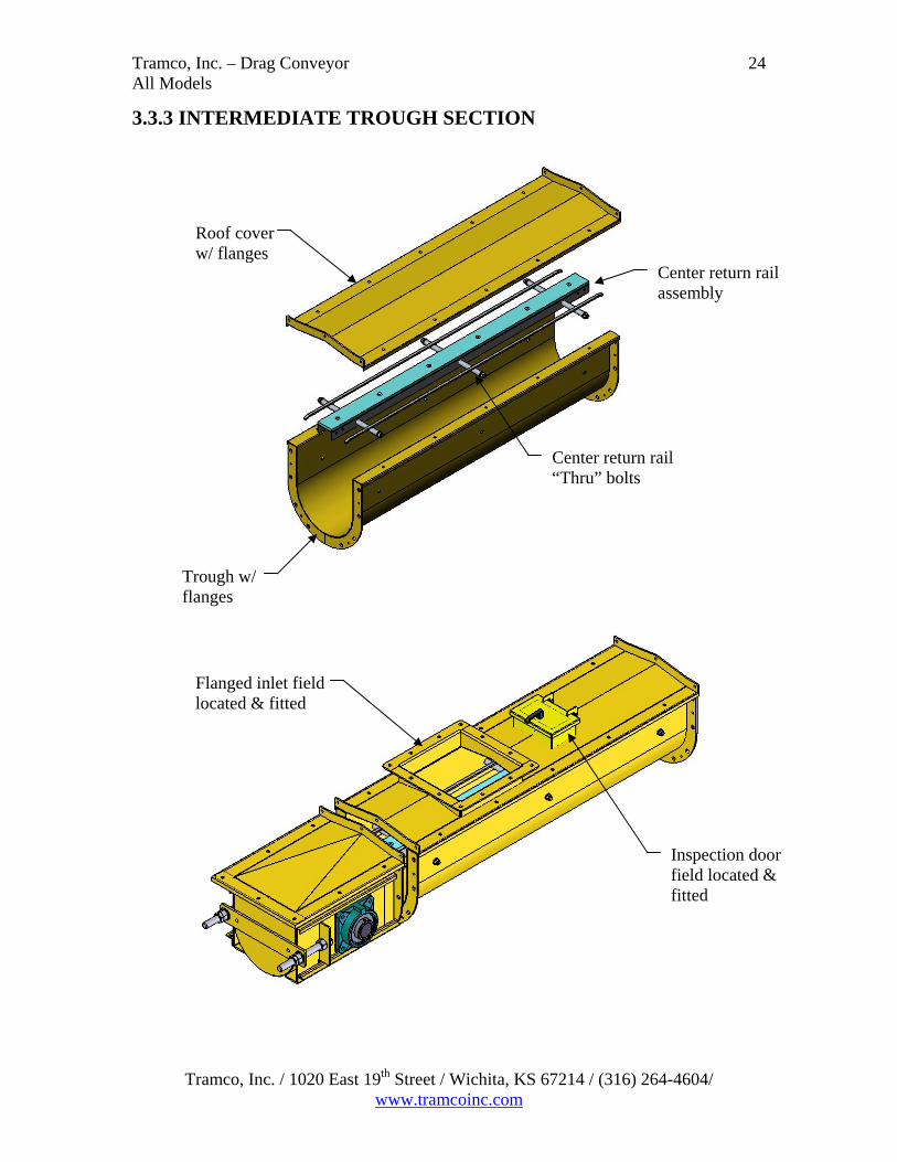
3.3.3 INTERMEDIATE TROUGH SECTION
Roof cover w/ flanges
Center return rail assembly
Center return rail “Thru” bolts
Trough w/ flanges
Flanged inlet field located & fitted
Inspection door field located & fitted
Tramco, Inc. / 1020 East 19th Street / Wichita, KS 67214 / (316) 264-4604/ www.tramcoinc.com

Tramco, Inc. – Drag Conveyor All Models
25
3.3.4 SEALS
Bearing Plate
UHMW Shaft Seal
Bearing
Head &Tail Seal
Tramco, Inc. / 1020 East 19th Street / Wichita, KS 67214 / (316) 264-4604/ www.tramcoinc.com

Tramco, Inc. – Drag Conveyor All Models
26
3.3.5 CONVEYOR CHAIN & FLIGHTS
Connecting pin
The bottom surface of UHMW flight is called the “Carrying side”
“T” head cotter pin
The chain installed direction of travel is called the “Bottom strand”
Attachment bar
Welded chain (Shown w/ 4” pitch)
Note: The direction of travel shown by the arrow is toward the head.
Tramco, Inc. / 1020 East 19th Street / Wichita, KS 67214 / (316) 264-4604/ www.tramcoinc.com

Tramco, Inc. – Drag Conveyor All Models
27
3.3.6 ASSEMBLY BOLTS & ALIGNMENT PINS
Intermediate connecting flange
(4) Alignment pins w/ cotter keys each joint, typical
Apply sealant to each face at the joint, typical
Note: Care should be exercised when joining sections of the conveyor to see that the “Carryback”, “Return Rails” and/or “Splice Angles” are properly aligned. The top surface of the joints should be flush and smooth with no projecting lips to catch the flights or flight facings. If there is a misalignment, loosen the “trough” bolts and adjust as required.
Tramco, Inc. / 1020 East 19th Street / Wichita, KS 67214 / (316) 264-4604/ www.tramcoinc.com

Tramco, Inc. – Drag Conveyor All Models
28
3.4 TRAMCO BULK-FLO™ The Tramco BULK-FLO™ heavy-duty chain conveyor is designed to handle a wide variety of challenging materials such as wet and sticky products, those with varying sizes and densities, and abrasive or corrosive materials. The unsurpassed quality and rugged construction of the BULK-FLO™ conveyor series assures years of dependable service even under the most severe conditions. Each system is individually designed for your specific application from standard components that are robotically welded in jig fixtures to provide interchangeability and smooth operation. All head and tail sections are maintenance friendly and wear parts are easily replaced.
Each Tramco BULK-FLO™ En-Masse chain conveyor consists of the following components: Head Discharge Section with Drive Shaft Tail Section with Take-up Assembly Intermediate Trough Section Rino Seals Conveyor Chain & Flights Assembly Bolts & Alignment pins Graphical representations of the components of the Tramco BULK-FLO™ can be found in sections 3.4.1 – 3.4.6 The graphical representations of the components of the Tramco BULK-FLO™ are representative drawings only. It is the responsibility of the purchaser to consult contract drawings for specific items on each conveyor.
Tramco, Inc. / 1020 East 19th Street / Wichita, KS 67214 / (316) 264-4604/ www.tramcoinc.com

Tramco, Inc. – Drag Conveyor All Models
29
3.4.1 HEAD DISCHARGE SECTION WITH DRIVE SHAFT
Head discharge section w/ bolted removable cover
Trough assembly match marks, typical
3.4.2 TAIL SECTION WITH TAKE-UP ASSEMBLY
Trough assembly match marks, typical
Tail section w/ bolted removable cover
Intermediate trough section
Trough assembly match marks, typical
Tramco, Inc. / 1020 East 19th Street / Wichita, KS 67214 / (316) 264-4604/ www.tramcoinc.com

Tramco, Inc. – Drag Conveyor All Models
30
3.4.3 INTERMEDIATE TROUGH SECTION
Roof cover w/ flanges
Top Side panel w/ flanges
Divider Plate
Bottom Side panel w/ flanges
Bottom panel w/ flanges
Flanged inlet field located & fitted
Inspection door field located & fitted
Tramco, Inc. / 1020 East 19th Street / Wichita, KS 67214 / (316) 264-4604/ www.tramcoinc.com

Tramco, Inc. – Drag Conveyor All Models
31
3.4.4 RINO SEALS
Mounting plate 1/4” Rope seals
Inner rings
Seal rings
Outer ring
Head Rino Seal
Spacer bar
Take-up plate
Bar
1/4” Rope seals
Ring “A” Typical
Seal rings UHMW seal
Ring “B” Typical
Retainer
Tail Rino Seal
Tramco, Inc. / 1020 East 19th Street / Wichita, KS 67214 / (316) 264-4604/ www.tramcoinc.com

Tramco, Inc. – Drag Conveyor All Models
32
3.4.5 CONVEYOR CHAIN & FLIGHTS
“T” head cotter pin
Attachment bar or Attachment angle
Connecting pin
Backing plate
Angled Flight (Shown at 30°)
Face barsWelded chain (Shown w/ 6” pitch)
The bottom surface of UHMW flight is called the “Carrying side”
The chain installed direction of travel is called the “Bottom strand”
Note: The direction of travel shown by the arrow is toward the head.
Note: Flight Assembly configurations with straight flights and 15° angled flights are available.
Typical Chain and Flight Assembly
Tramco, Inc. / 1020 East 19th Street / Wichita, KS 67214 / (316) 264-4604/ www.tramcoinc.com

Tramco, Inc. – Drag Conveyor All Models
33
3.4.6 ASSEMBLY BOLTS & ALIGNMENT PINS
Intermediate connecting flange
(12) Alignment pins w/ cotter keys each joint, typical
Apply sealant to each face at the joint, typical
Tramco, Inc. / 1020 East 19th Street / Wichita, KS 67214 / (316) 264-4604/ www.tramcoinc.com

Tramco, Inc. – Drag Conveyor All Models
34
3.4.7 ADDITIONAL TAKE-UP OPTION
Cross Section of Additional Take-Up Options
(Shown with the Single and Double Take-Up Configurations)
Top View of Additional Take-Up Options (Shown with the Single and Double Take-Up Configuration)
Note: Both the Single and Dual Chain configurations of the Additional Take-Up Options are available on the Tramco MODEL G™ and Tramco BULK-FLO™ models.
Tramco, Inc. / 1020 East 19th Street / Wichita, KS 67214 / (316) 264-4604/ www.tramcoinc.com

Tramco, Inc. – Drag Conveyor All Models
35
3.5 GENERAL ARRANGEMENT DRAWINGS
Gate Clamp
Section A-A A
A
Note: The “L” and “C” Style gates can be used on both the Tramco MODEL G™ and Tramco BULK-FLO™
Torque arm bracket (For motorized option only)
Gate operator: Manual, motorized, or air. (Air not shown)
Carry over bars (Mounted flush w/ inside top of bottom plate)
Bottom plate
“L” Style Gate (Shown on an intermediate section of MODEL G™)
Tramco, Inc. / 1020 East 19th Street / Wichita, KS 67214 / (316) 264-4604/ www.tramcoinc.com
Tramco, Inc. – Drag Conveyor All Models
36
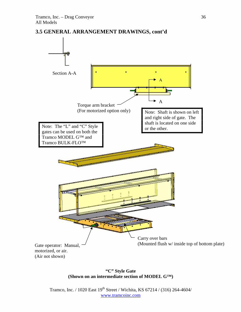
3.5 GENERAL ARRANGEMENT DRAWINGS, cont’d
Section A-A
A
Torque arm bracket (For motorized option only)
A
Note: Shaft is shown on left and right side of gate. The shaft is located on one side or the other.
Note: The “L” and “C” Style gates can be used on both the Tramco MODEL G™ and Tramco BULK-FLO™
Carry over bars (Mounted flush w/ inside top of bottom plate)
Gate operator: Manual, motorized, or air. (Air not shown)
“C” Style Gate
(Shown on an intermediate section of MODEL G™)
Tramco, Inc. / 1020 East 19th Street / Wichita, KS 67214 / (316) 264-4604/ www.tramcoinc.com

Tramco, Inc. – Drag Conveyor All Models
37
3.5 GENERAL ARRANGEMENT DRAWINGS, cont’d
Replaceable liners
Removable side panels
Removable side panels
Replaceable liners
Bypass Inlet (Shown on an intermediate section of MODEL G™)
Note: Bypass Inlets are also available for both the Tramco MODEL RB™ and Tramco BULK-FLO™ models.
Tramco, Inc. / 1020 East 19th Street / Wichita, KS 67214 / (316) 264-4604/ www.tramcoinc.com

Tramco, Inc. – Drag Conveyor All Models
38
Tramco, Inc. / 1020 East 19th Street / Wichita, KS 67214 / (316) 264-4604/ www.tramcoinc.com
3.5 GENERAL ARRANGEMENT DRAWINGS, cont’d
Internal Scoop Assembly (Shown on a tail section of MODEL G™)
Note: The Internal Scoop assembly is also available on a BULK-FLO™ tail assembly.
Internal scoop plate assembly
Internal scoop plate assembly
Standard Tail Assembly
Internal scoop shown in final position
Internal scoop shown in initial position
UHMW seals
Tramco, Inc. – Drag Conveyor All Models
39
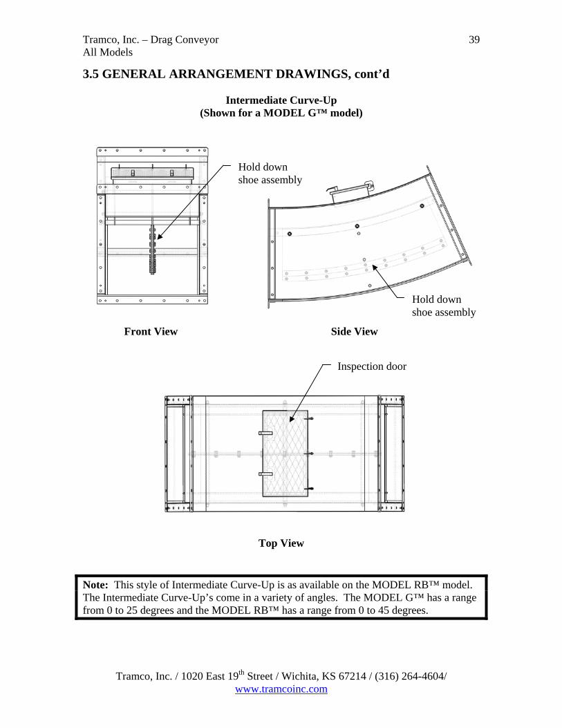
3.5 GENERAL ARRANGEMENT DRAWINGS, cont’d
Intermediate Curve-Up (Shown for a MODEL G™ model)
Hold down shoe assembly
Hold down shoe assembly
Front View Side View
Inspection door
Top View
Note: This style of Intermediate Curve-Up is as available on the MODEL RB™ model. The Intermediate Curve-Up’s come in a variety of angles. The MODEL G™ has a range from 0 to 25 degrees and the MODEL RB™ has a range from 0 to 45 degrees.
Tramco, Inc. / 1020 East 19th Street / Wichita, KS 67214 / (316) 264-4604/ www.tramcoinc.com
Tramco, Inc. – Drag Conveyor All Models
40
Tramco, Inc. / 1020 East 19th Street / Wichita, KS 67214 / (316) 264-4604/ www.tramcoinc.com
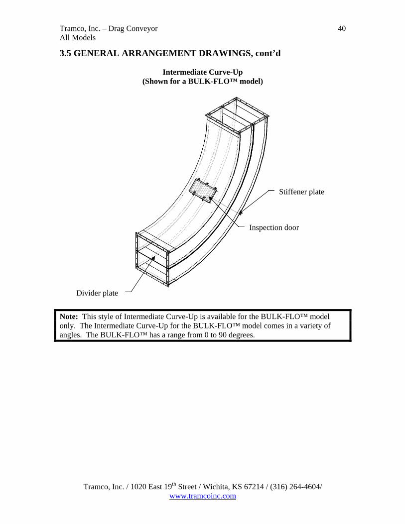
3.5 GENERAL ARRANGEMENT DRAWINGS, cont’d
Intermediate Curve-Up (Shown for a BULK-FLO™ model)
Note: This style of Intermediate Curve-Up is available for the BULK-FLO™ model only. The Intermediate Curve-Up for the BULK-FLO™ model comes in a variety of angles. The BULK-FLO™ has a range from 0 to 90 degrees.
Inspection door
Divider plate
Stiffener plate

Tramco, Inc. – Drag Conveyor All Models
41
3.6 GENERAL ASSEMBLY INSTRUCTIONS
WARNING
To minimize risk of serious injury, death or property damage, follow the safety instructions in this manual concerning assembly.
Inlet Inspection door
Flight Assembly
Tail Section w/ take-up
Head Section
Figure A: Tramco Model GTM
Discharge Gate (Optional)
(Shown with optional “C” Style motorized gate)
Trough section
Inlet Inspection door
Figure B: Tramco Model RB
Tail Section (Shown with fixed tail)
Flight hold-down
Head Section
Tramco, Inc. / 1020 East 19th Street / Wichita, KS 67214 / (316) 264-4604/ www.tramcoinc.com

Tramco, Inc. – Drag Conveyor All Models
42
3.6 GENERAL ASSEMBLY INSTRUCTIONS cont’d
Head Section
Trough section at tail end
Inspection door Inlet
Tail Section w/ take-up
Figure C: Tramco Bulk – Flo
(Shown with a 90° curve)
Figures A, B, & C are representative drawings only. It is the responsibility of the purchaser to consult contract drawings for specific items on each conveyor. For safety and proper operation, drag conveyors must be assembled and erected straight and true. The purchaser is responsible for ensuring all support and mounting surfaces are straight and level so there is no distortion in the conveyor. All component pieces (or conveyor sections) should be placed in proper sequence before assembly is started. For shop-assembled conveyors, units are match marked and shipped in the longest sections practical for shipment. Field assembly can be accomplished by connecting marked joints in accordance with the packing list and/or drawing if applicable. In field erection, the mounting surfaces for supporting the conveyor must be level and true so there is no distortion in the conveyor. Shims or grout should be used when required. Frequently check for straightness during assembly.
Tramco, Inc. / 1020 East 19th Street / Wichita, KS 67214 / (316) 264-4604/ www.tramcoinc.com

Tramco, Inc. – Drag Conveyor All Models
43
3.6 GENERAL ASSEMBLY INSTRUCTIONS cont’d For conveyor assemblies purchased as parts or merchandise, assemble according to the following procedure: 1. Use the trough assembly match marks to place the conveyor troughs in proper
sequence with the tail section, the bypass inlet (if applicable), and the head section in their proper locations. Connect the trough flanges loosely. Do not tighten bolts.
2. Align the trough bottom centerlines perfectly using the alignment pins; apply appropriate sealant (caulking, silicon, Gortex, or neoprene); then tighten flange bolts to manufacturer’s torque specifications.
3. Tighten all anchor bolts to manufacturer’s torque specifications. 4. Before connecting the top section of chain, loosen take-up as much as possible.
Check sprocket alignment. Check set screws and bearing bolts for tightness. 5. Connect top section for the chain. Refer to 3.6.1 Chain Assembly Instructions Note: On long conveyors, the use of a come-a-long may be necessary. 6. Adjust take-up to remove excess slack from chain making sure that adjustment screws
have been tightened equally to prevent misalignment (Refer to General Arrangement Drawing section).
7. Install trough covers in the proper sequence. Handle covers with reasonable care to avoid warping or bending. Covers should be securely fastened.
8. Install drive at the proper location and in accordance with separate instructions provided.
9. Rotate conveyor manually to ensure that no binding occurs. 10. Check for proper direction of chain and flight travel after electrical connections have
been made and before attempting to handle material. 11. If necessary, after lockout/ tagout, reconnect electrical leads to reverse direction of
material flow. Material should be pushed by the flight and attachment. 12. Attach all gates, feed chute, discharge chute, etc., and connect all safety devices and
controls according to the assembly drawing for your conveyor. Carefully test each to ensure proper operation.
Tramco, Inc. / 1020 East 19th Street / Wichita, KS 67214 / (316) 264-4604/ www.tramcoinc.com

Tramco, Inc. – Drag Conveyor All Models
44
3.6.1 CHAIN ASSEMBLY INSTRUCTIONS The safest install position for the chain may depend upon the conveyor shape and its install position in the plant. It is therefore necessary for the supervisor to be consulted and the necessary Risk Assessments prepared prior to assembling the chain. Ensure that any lifting, supporting, or any other method of securing the chain is
suitable for the application. Prior to splitting the chain at the Head of an incline conveyor, the chain must be
secured at both sides of the split position to prevent the chain from falling into the conveyor.
Begin assembling 10ft (3 meters) sections of chain together and pull it into the conveyor through the tail section or at an accessible position through the top of the conveyor
Continue adding sections of chain while feeding and pulling chain through the conveyor. The chain should be passed under the tail sprocket, through the bottom trough, towards the head end, then around the head sprocket and back to the tail section.
The final connecting pin may be installed at the tail sprocket with the tail quarter section cover removed.
CHAIN CONNECTING PINS: The connecting pins have a shoulder diameter at the head end of the pin, there is a correspondingly larger hole at one side of the chain link, thus providing an interference fit between the links and pin. Therefore, care must be taken to assemble the pin from the correct side of the link. It is recommended to lubricate the pins with appropriate lubricant to assist installation. After the connecting pins are in place, fit and bend the clevis pin to lock in place. Finally, check that the joined links do not bind or kink the chain. If this happens, hit the tail end of the pin with a hammer to release the side load on the pin.
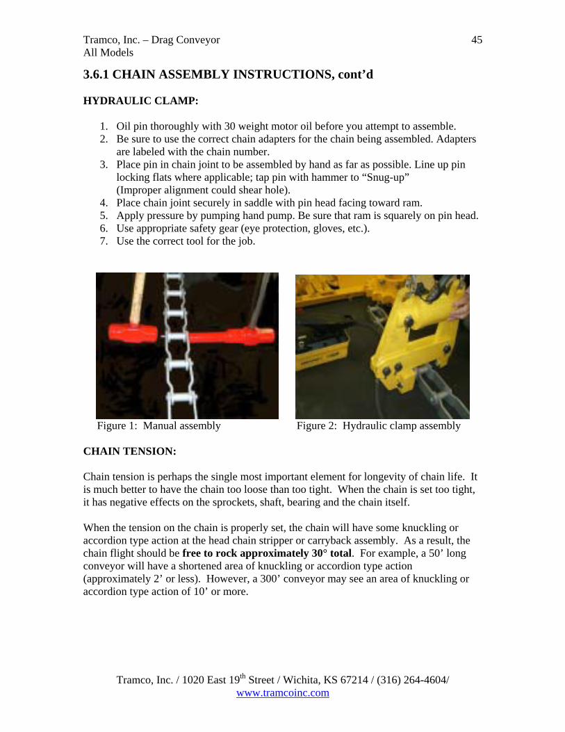
DO NOT GRIND OR MODIFY THE CHAIN CONNECTING PIN The chain can be assembled manually or with an air assist hydraulic clamp. Note: The easiest and most effective way of connecting the 10 ft (3 meters) chain sections is using a portable air assist hydraulic clamp (Refer to Figure 2). Listed below are the instructions for both methods. MANUAL:
1. Oil pin thoroughly with 30 weight motor oil before you attempt to assemble.
2. It is important to use a heavy back up bar counter board to receive the pin. 3. Manually insert the pin through both sidebars to ensure a proper alignment. 4. Strike the head of the pin with a mighty force until the pin head is flush with the
sidebar.
Tramco, Inc. / 1020 East 19th Street / Wichita, KS 67214 / (316) 264-4604/ www.tramcoinc.com
Tramco, Inc. – Drag Conveyor All Models
Tramco, Inc. / 1020 East 19th Street / Wichita, KS 67214 / (316) 264-4604/ www.tramcoinc.com
45
3.6.1 CHAIN ASSEMBLY INSTRUCTIONS, cont’d HYDRAULIC CLAMP:
1. Oil pin thoroughly with 30 weight motor oil before you attempt to assemble. 2. Be sure to use the correct chain adapters for the chain being assembled. Adapters
are labeled with the chain number. 3. Place pin in chain joint to be assembled by hand as far as possible. Line up pin
locking flats where applicable; tap pin with hammer to “Snug-up” (Improper alignment could shear hole). 4. Place chain joint securely in saddle with pin head facing toward ram. 5. Apply pressure by pumping hand pump. Be sure that ram is squarely on pin head. 6. Use appropriate safety gear (eye protection, gloves, etc.). 7. Use the correct tool for the job.
Figure 1: Manual assembly Figure 2: Hydraulic clamp assembly CHAIN TENSION: Chain tension is perhaps the single most important element for longevity of chain life. It is much better to have the chain too loose than too tight. When the chain is set too tight, it has negative effects on the sprockets, shaft, bearing and the chain itself. When the tension on the chain is properly set, the chain will have some knuckling or accordion type action at the head chain stripper or carryback assembly. As a result, the chain flight should be free to rock approximately 30° total. For example, a 50’ long conveyor will have a shortened area of knuckling or accordion type action (approximately 2’ or less). However, a 300’ conveyor may see an area of knuckling or accordion type action of 10’ or more.

Tramco, Inc. – Drag Conveyor All Models
46
3.6.1 CHAIN ASSEMBLY INSTRUCTIONS, cont’d CHAIN TENSION cont’d:
Area of Knuckling or Accordion type action
Figure 1: The chain is too tight
(Shown at the head of the BULK FLOTM)
Area of Knuckling or Accordion type action with 30° maximum flight rock
Figure 2: The tension on the chain is ideal (Shown at the head of the BULK FLOTM)
Area of Knuckling or Accordion type action
Figure 3: The chain is too loose
(Shown at the head of the BULK FLOTM)
Note: The chain tension conditions shown in the figures above are representative. The 30° maximum flight rock applies to all models of Tramco En Masse Chain Conveyors. There are many different locations, based on the layout of the conveyor, where the chain tension can be inspected.
Tramco, Inc. / 1020 East 19th Street / Wichita, KS 67214 / (316) 264-4604/ www.tramcoinc.com

Tramco, Inc. – Drag Conveyor All Models
47
3.6.1 CHAIN ASSEMBLY INSTRUCTIONS, cont’d CHAIN TENSION cont’d: Area of Knuckling or
Accordion type action
Area of Knuckling or Accordion type action with 30° maximum flight rock
Area of Knuckling or Accordion type action
Figure 1: The chain is too tight
(Shown at the head of the MODEL GTM)
Figure 2: The tension on the chain is ideal (Shown at the head of the MODEL GTM)
Figure 3: The chain is too loose
(Shown at the head of the MODEL GTM)
Note: The chain tension conditions shown in the figures above are representative. The 30° maximum flight rock applies to all models of Tramco En Masse Chain Conveyors. There are many different locations, based on the layout of the conveyor, where the chain tension can be inspected.
Tramco, Inc. / 1020 East 19th Street / Wichita, KS 67214 / (316) 264-4604/ www.tramcoinc.com

Tramco, Inc. – Drag Conveyor All Models
48
3.7 COMPONENT INFORMATION DRIVE: Installation: Depending on the type and size of the drive, and the customer order, it may be necessary to site fabricate a support/ torque absorption point from a suitable structure. Fit the drive per the instructions in the drive manufacturer’s manual. Replacement: Refer to the drive manufacturer’s manual. Consult contract drawings for specific drive details used on the conveyor. Note the weight for lifting purposes. Follow the Lockout/ Tagout procedures in this manual. BEARINGS: Installation: Install the bearings per the instructions in the bearing manufacturer’s manual. Replacement: Refer to the bearing manufacturer’s manual for replacement recommendations for bearings operating at low speed. Consult contract drawings for specific bearing details used on the conveyor. Note: If the conveyor is a Vapor Tight model, the tail section will have phosphor bronze bushings in the steel housing in lieu of bearings. Use the following procedure to remove and/or replace the bushings.
1. Remove tail covers. 2. Disconnect the conveyor chain. 3. Remove both chain adjustment studs. 4. Push the tail shaft to one side of the tail. The opposite side bushing can
now be removed. 5. Slide the bushing housing to the gap in the guide bars and remove. 6. Remove slotted locking screw. 7. Release locking ring from the bushing housing by drifting in an anti-
clockwise direction with a hammer and suitable bar. 8. Completely remove locking ring. 9. The bushing can now be pressed from the bearing housing.
Tramco, Inc. recommends that bearings (or bushings) and seals be replaced every 2 years, or have vibration and/or temperature monitoring (done by others) carried out to ensure continued safe operation.
Tramco, Inc. / 1020 East 19th Street / Wichita, KS 67214 / (316) 264-4604/ www.tramcoinc.com

Tramco, Inc. – Drag Conveyor All Models
49
3.7 COMPONENT INFORMATION, cont’d SEALS: Installation: Refer to the appropriate section of this manual for an exploded isometric view of the Head and Tail Rino seal. Install the Rino seals as shown in this manual. Refer to bolt suppliers for bolt torque specifications. Replacement: The Head section and Tail Section Rino seals can be replaced by sliding the Inner and Outer rings along the shaft, prying out the rope seal, and fitting a new rope seal. Note: The Vapor Tight model conveyor has a conventional gland packing seal in lieu of the Rino seal. The gland packer fasteners should be tightened until the gland packing is compressed against the shaft and then tightened another quarter turn. Tramco, Inc. recommends that bearings (or bushings) and seals be replaced every 2 years, or have vibration and/or temperature monitoring (done by others) carried out to ensure continued safe operation. Note: All manufacturer’s manuals, product information, and data sheets will be shipped with each conveyor. It is the responsibility of the contractor, installer, owner, and user to read and follow the manufacturer’s installation instructions and maintenance recommendations.
Tramco, Inc. / 1020 East 19th Street / Wichita, KS 67214 / (316) 264-4604/ www.tramcoinc.com
Tramco, Inc. – Drag Conveyor All Models
50
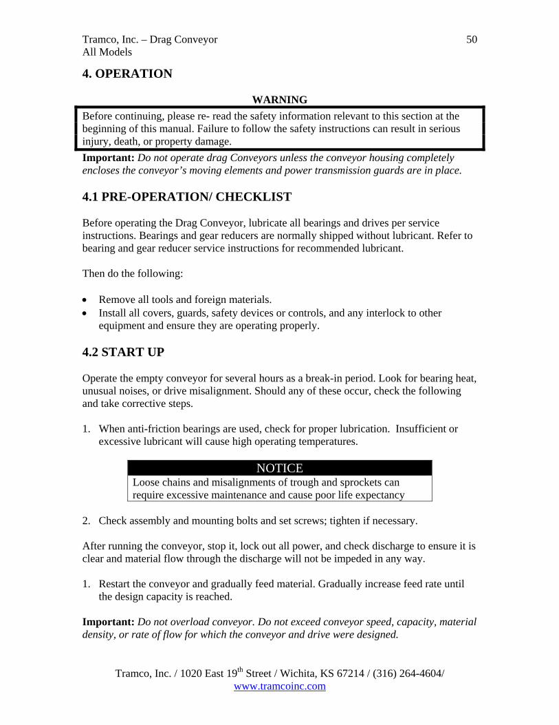
4. OPERATION
WARNING
Before continuing, please re- read the safety information relevant to this section at the beginning of this manual. Failure to follow the safety instructions can result in serious injury, death, or property damage.
Important: Do not operate drag Conveyors unless the conveyor housing completely encloses the conveyor’s moving elements and power transmission guards are in place. 4.1 PRE-OPERATION/ CHECKLIST Before operating the Drag Conveyor, lubricate all bearings and drives per service instructions. Bearings and gear reducers are normally shipped without lubricant. Refer to bearing and gear reducer service instructions for recommended lubricant. Then do the following: Remove all tools and foreign materials. Install all covers, guards, safety devices or controls, and any interlock to other
equipment and ensure they are operating properly. 4.2 START UP Operate the empty conveyor for several hours as a break-in period. Look for bearing heat, unusual noises, or drive misalignment. Should any of these occur, check the following and take corrective steps. 1. When anti-friction bearings are used, check for proper lubrication. Insufficient or
excessive lubricant will cause high operating temperatures.
NOTICE Loose chains and misalignments of trough and sprockets can require excessive maintenance and cause poor life expectancy
2. Check assembly and mounting bolts and set screws; tighten if necessary.
After running the conveyor, stop it, lock out all power, and check discharge to ensure it is clear and material flow through the discharge will not be impeded in any way. 1. Restart the conveyor and gradually feed material. Gradually increase feed rate until
the design capacity is reached. Important: Do not overload conveyor. Do not exceed conveyor speed, capacity, material density, or rate of flow for which the conveyor and drive were designed.
Tramco, Inc. / 1020 East 19th Street / Wichita, KS 67214 / (316) 264-4604/ www.tramcoinc.com

Tramco, Inc. – Drag Conveyor All Models
51
4.2 START UP, cont’d 2. Cut off feed and allow the conveyor to empty. Lock out power supply. Check all bolts
and all alignments. Re-align as necessary, tighten all bolts, and check chain adjustment.
3. Check motor amperage frequently during start up. 4. Check chain tension periodically during start up. It may be necessary to re-adjust
chain tension after running material in the conveyor. 4.3 GENERAL Run the conveyor empty for a few minutes periodically to check for excessive
vibration, loose fasteners, security of covers and guards, noise, and bearing and drive temperature.
Always operate the conveyor with covers, guards, and safety labels in place. Always practice good housekeeping and keep a clear view of the conveyor loading,
discharges, and all safety devices. If the conveyor won’t be operated for a prolonged period of time, operate until
cleared of all material. This is particularly important when the material conveyed tends to harden, becomes more viscous or sticky, or spoils if allowed to stand for a long period of time.
DANGER
Rotating parts hazard! To avoid serious injury or death, keep body, hair, and clothing away from rotating pulleys, belts, chains, and sprockets. Keep all guards in place and in good working order. Lockout/ Tagout power before removing guard
4.4 EXTENDED SHUTDOWN/ STORAGE If the conveyor will be shutdown for more than one month, perform the following: 1. Remove all foreign material from the conveyor and check that the surface coatings
are in good order. 2. Lubricate and protect all bearings and drives according to the manufacturer's
instructions. 3. Rotate the gear reducer periodically according to the manufacturer's instructions. 4. Protect the conveyor from weather, moisture, and extreme temperatures as required.
Do not use plastic or other coverings that promote condensation under the covering. 5. Coat all exposed metal surfaces with rust preventative oil. Follow all the
manufacturer's instructions that come with the rust preventative oil. 6. Prior to a subsequent start-up, perform the installation and operation instructions in
this manual.
Tramco, Inc. / 1020 East 19th Street / Wichita, KS 67214 / (316) 264-4604/ www.tramcoinc.com
Tramco, Inc. – Drag Conveyor All Models
52
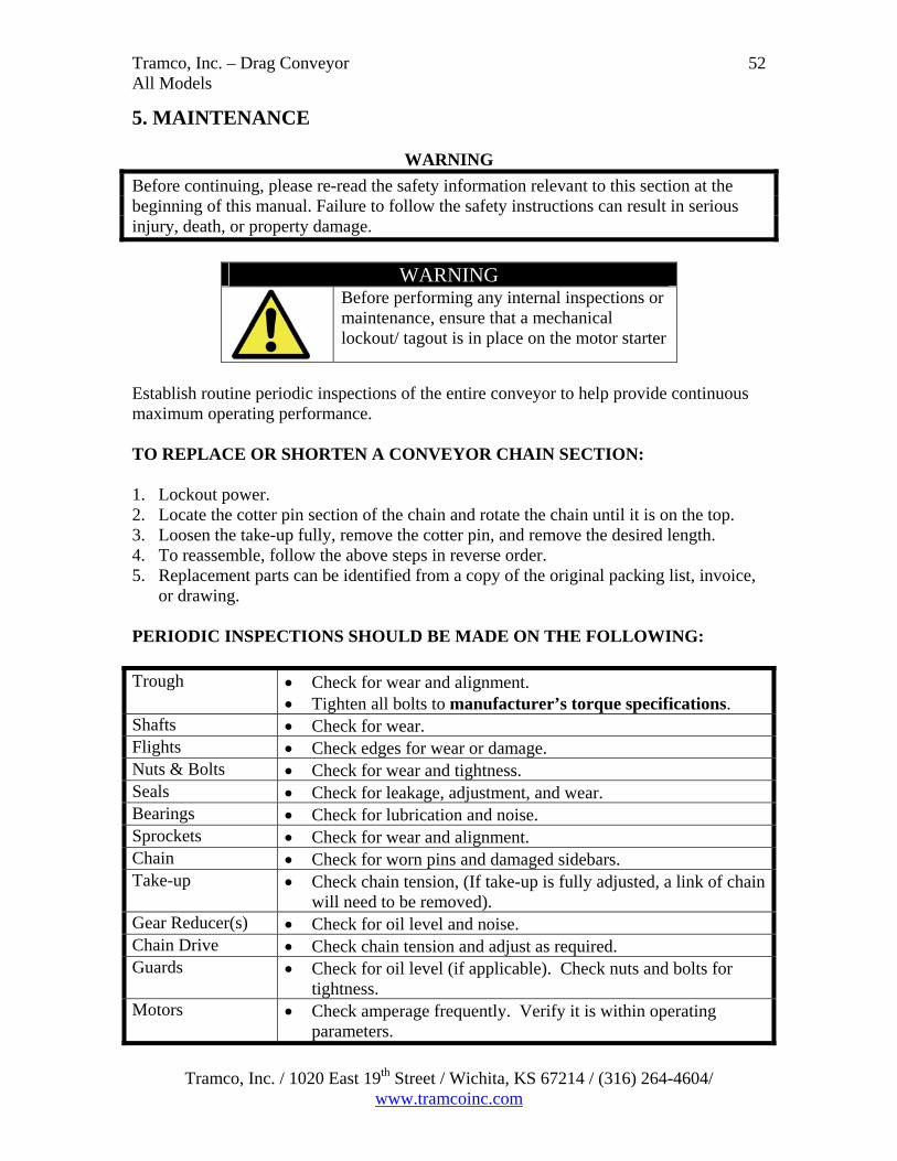
5. MAINTENANCE
WARNING
Before continuing, please re-read the safety information relevant to this section at the beginning of this manual. Failure to follow the safety instructions can result in serious injury, death, or property damage.
WARNING
Before performing any internal inspections or maintenance, ensure that a mechanical lockout/ tagout is in place on the motor starter
Establish routine periodic inspections of the entire conveyor to help provide continuous maximum operating performance. TO REPLACE OR SHORTEN A CONVEYOR CHAIN SECTION: 1. Lockout power. 2. Locate the cotter pin section of the chain and rotate the chain until it is on the top. 3. Loosen the take-up fully, remove the cotter pin, and remove the desired length. 4. To reassemble, follow the above steps in reverse order. 5. Replacement parts can be identified from a copy of the original packing list, invoice,
or drawing. PERIODIC INSPECTIONS SHOULD BE MADE ON THE FOLLOWING:
Trough Check for wear and alignment. Tighten all bolts to manufacturer’s torque specifications.
Shafts Check for wear. Flights Check edges for wear or damage. Nuts & Bolts Check for wear and tightness. Seals Check for leakage, adjustment, and wear. Bearings Check for lubrication and noise. Sprockets Check for wear and alignment. Chain Check for worn pins and damaged sidebars. Take-up Check chain tension, (If take-up is fully adjusted, a link of chain
will need to be removed). Gear Reducer(s) Check for oil level and noise. Chain Drive Check chain tension and adjust as required. Guards Check for oil level (if applicable). Check nuts and bolts for
tightness. Motors Check amperage frequently. Verify it is within operating
parameters.
Tramco, Inc. / 1020 East 19th Street / Wichita, KS 67214 / (316) 264-4604/ www.tramcoinc.com

Tramco, Inc. – Drag Conveyor All Models
53
5.1 CHAIN & FLIGHTS EXAMINATION FOR WEAR: Periodically, the Chain should be examined for wear. The period between examinations may vary based on the power used, abrasiveness of material, shape of the conveyor, Planned Maintenance stops, etc. At a minimum, the chain should be checked twice a year. In practice, maintenance records provide the best indication of chain deterioration, It’s normal for Chain and Flights to ‘bed in’ during the first month or so of constant running. Measuring, comparing, and recording the Pin wear regularly is likely to show that the chain wear remains relatively stable after the chain has ‘bedded in’. If that’s not the case, examine the pin to see if corrosion or abrasion is the main problem. Once the problem is determined, call Tramco, Inc. about the results. With good Maintenance Records, it’s easier to predict when to replace the chain in any particular conveyor. REPLACEMENT: Here is a list of some indications that a chain is nearing its replacement point. If possible, remove a conveyor cover, measure the distance between pin centers over
20 links. Compare the length of 20 chain pitches with the measured length. If the chain has worn +5%, it should be changed.
Remove a Pin from the chain and examine the outside diameter. Normal bedding in will occur and is not a problem unless the Pin has a significant step. Measure and record the pin diameter on the Maintenance Record.
Examine the flights. If the UHMW (if used) has worn down to the supporting metal, the Flights must be changed. If there are cracks in the Flights, they must be changed.
Remove the accessible old Flights, replace with new flights. Clear all tools etc. from inside the conveyor. Note: If the conveyor flights have stainless steel locknuts fitted, they must be replaced.
Examine the welds - attachment bar to link side bar. If cracks are evident, the chain link must be changed.
5.2 SPROCKETS EXAMINATION FOR WEAR: Periodically, examine the sprockets for signs of wear. Normal bedding in will occur and is not a problem until the driving face flank of the tooth begins to wear into a ‘hook’ shape. A worn sprocket will cause premature chain wear through bad contact and a rubbing action on the chain barrels and should be replaced. In extreme cases, the hook will drive the chain down past its normal release point causing damage to the Carry-Backs, Intermediate plate or causing the chain to wrap around the sprocket and break.
Tramco, Inc. / 1020 East 19th Street / Wichita, KS 67214 / (316) 264-4604/ www.tramcoinc.com

Tramco, Inc. – Drag Conveyor All Models
54
5.2 SPROCKETS, cont’d EXAMINATION FOR WEAR cont’d: 3/16”
1/2”
Figure 1: Good Figure 2: Bad Figure 3: Worst
The figures above represent the wear conditions of the sprockets. After the sprocket is worn or hooked from 3/16” to 1/4" (As shown in Figures 1 & 2), it is very important to replace the sprockets in order to avoid irreversible harm to the barrel of the chain. If the wear condition of the sprocket meets or exceeds the condition shown in Figure 3, not only do the sprockets need to be replaced, but further examination of the individual chain components is required. Tramco, Inc. sprockets are split for easy removal. Note: Larger sprockets can come with lifting points for easy handling. This option must be requested by the customer at the time the order is placed.
REPLACEMENT: Remove the Head or Tail access covers. Split the chain. Refer to the Chain Assembly & Safety Sections. In the case of inclined conveyors, support both halves of the Sprocket so they cannot
fall into the conveyor. Remove fasteners and sprocket halves. Retain the shaft drive key. Clean up the shaft. Loose fit the two halves of the new Sprocket onto the shaft using new fasteners
coated with ‘Studlock VC302’ or equivalent. Position the Sprocket in the center of the Head Casing and fully tighten the fasteners.
Check that the sprocket is on the conveyor centerline.
Tramco, Inc. / 1020 East 19th Street / Wichita, KS 67214 / (316) 264-4604/ www.tramcoinc.com

Tramco, Inc. – Drag Conveyor All Models
55
6. TROUBLESHOOTING
PROBLEM CAUSE SOLUTION
Gauge too thin Increase thickness. Consult Tramco, Inc. for recommendations
Worn flights Replace flights
Premature Trough Failure
Excessive chain speed
Check Chain Speed
Excessive heat Change flight material. UHMW is limited to 175° F
Speed too high Reduce speed. Consult Tramco, Inc. to determine proper chain speed.
Accelerated Flight Wear
Foreign objects Remove foreign objects Worn chain Replace chain if worn Take-up is loose Adjust take-up Obstruction in
conveyor Remove obstruction
Sprocket mis-alignment
Align sprockets
Plugged discharge Remove material from discharge
Chain Breakage
Overloading conveyor
Regulate feed into conveyor
Excessive torque Recalculate horsepower requirements
Insufficient torque capacity
Increase shaft diameter Change shaft material
Obstruction in conveyor
Remove obstruction
Drive Shaft Breakage
Overloading conveyor
Regulate feed into conveyor
Material getting into bearing
Add or upgrade seal to keep material out of bearing
Change outboard bearing
Bearing Failure
Insufficient/Excessive lubrication
Lubricate properly
Tramco, Inc. / 1020 East 19th Street / Wichita, KS 67214 / (316) 264-4604/ www.tramcoinc.com
Tramco, Inc. – Drag Conveyor All Models
56
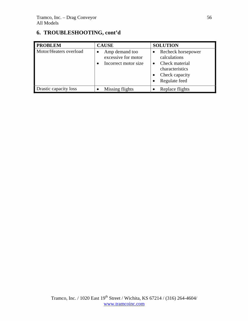
6. TROUBLESHOOTING, cont’d
PROBLEM CAUSE SOLUTION Motor/Heaters overload Amp demand too
excessive for motor Incorrect motor size
Recheck horsepower calculations
Check material characteristics
Check capacity Regulate feed
Drastic capacity loss Missing flights Replace flights
Tramco, Inc. / 1020 East 19th Street / Wichita, KS 67214 / (316) 264-4604/ www.tramcoinc.com

Tramco, Inc. – Drag Conveyor All Models
57
Terms and Conditions of Sale
LIMITED WARRANTY AND TERMS OF SALE WARRANTY: TRAMCO, INC. products are sold with a warranty against defects in material and workmanship for a period of one year from the date of their delivery to the purchaser or their delivery to the carrier in the case of F.O.B. Shipments. TRAMCO, INC.’s warranty shall be limited at TRAMCO, INC.’s option to repair or replacement of any defective parts or components. Such repair or replacement shall be the purchaser's exclusive remedy hereunder and correction of defects shall constitute complete fulfillment of all obligations and liabilities of TRAMCO, INC. with respect to the product sold hereunder, whether based in contract, tort, or otherwise. The determination of a defective condition shall be made by TRAMCO, INC. in its sole discretion. LIMITATION OF LIABILITY & REMEDIES: TRAMCO, INC. shall not be liable, in contract, tort, or otherwise, for any special indirect, incidental, or consequential damages, such as, but not limited to, loss of profits, loss of production, or for injury or damage, caused by reason of the installation, modification, use, repair, maintenance, or mechanical failure of any TRAMCO, INC. product. TRAMCO, INC.’s warranties hereunder extend only to the direct customer of TRAMCO, INC. TRAMCO, INC. makes no warranties of any kind with respect to improperly installed product or equipment unless the direct customer of TRAMCO, INC. (or first user, as the case may be) first fully discloses in writing to TRAMCO, INC. the method and details of the proposed installation and the intended use of the product or equipment and TRAMCO, INC. approves in writing of such method and details. TRAMCO, INC. makes no warranties when damage results from the failure to follow instructions in the manual or in safety labels attached to the TRAMCO, INC. system. The purchaser or user of any TRAMCO, INC. equipment shall be responsible for all ordinary maintenance, adjustments, and cleaning of the product. In the event that the TRAMCO, INC. product is not properly maintained, all warranties by TRAMCO, INC. are null and void. Certain of the component parts of the TRAMCO, INC. product are purchased from other vendors. TRAMCO, INC. warrants these component parts only to the extent of the vendor's warranties. TRAMCO, INC. shall repair or replace such component parts in accordance with the vendor's warranty policy only if TRAMCO, INC., in its sole discretion, determines such component parts to be defective. LOSS, DAMAGE OR DELAY: TRAMCO, INC. shall not be liable for any loss, damage, detention or delay resulting from any cause beyond its reasonable control, including, but not limited to, fire, strike or other concerted action of workmen, act or omission of any governmental authority or of the purchaser, insurrection, riot, embargo, transportation, shortage, delay or wreck, or inability to obtain labor or material from usual and customary sources.
Tramco, Inc. / 1020 East 19th Street / Wichita, KS 67214 / (316) 264-4604/ www.tramcoinc.com

Tramco, Inc. – Drag Conveyor All Models
58
WARRANTY DISCLAIMER: TRAMCO, INC. MAKES NO WARRANTIES OTHER THAN THOSE STATED HEREIN, AND THESE WARRANTIES ARE EXPRESSLY IN LIEU OF ALL OTHER WARRANTIES, WHETHER EXPRESS OR IMPLIED, INCLUDING BY WAY OF EXAMPLE AND NOT BY WAY OF LIMITATION, ANY WARRANTIES OF MERCHANTABILITY OR FITNESS FOR A PARTICULAR PURPOSE, AND ALSO IN LIEU OF ANY OTHER OBLIGATIONS OR LIABILITIES ON THE PART OF TRAMCO, INC.. MODIFICATIONS: The prices and terms of this offer are not subject to verbal changes or other agreements unless approved in writing by an authorized representative of TRAMCO, INC. management. No representation or warranty, express or implied, made by any sales representative or any agent or employee of TRAMCO, INC. which is not specifically set forth herein shall be binding on TRAMCO, INC. unless approved in writing by an authorized representative. TAXES: Unless otherwise noted, the price does not include any state or local property, sales, use, or privilege tax or license. If any such charge should be enforced by virtue of the transaction described herein, the purchaser agrees to pay the same or reimburse TRAMCO, INC., as the case may be. LOSS OR DAMAGE IN TRANSIT: Any claim for loss or damage to products in transit must be entered and prosecuted by the purchaser. RISK OF LOSS: Delivery shall occur and the risk of loss shall pass to the purchaser upon delivery of the material to the carrier at the point of shipment. Any claim of loss or damage in transit shall be against the carrier only. GENERAL PROVISION: The failure of TRAMCO, INC. to enforce any right will not be construed as a waiver of TRAMCO, INC.’s rights to performance in the future. The purchaser may not assign any rights or delegate any performance owed under this agreement without the express written consent of TRAMCO, INC. management.
Tramco, Inc. / 1020 East 19th Street / Wichita, KS 67214 / (316) 264-4604/ www.tramcoinc.com

Tramco, Inc. – Drag Conveyor All Models
59
CLAIM/NOTICE OF DEFECTS: In the event the purchaser claims that a TRAMCO, INC. product is damaged upon receipt, TRAMCO, INC. shall be given an equal opportunity for inspection, or, upon request, shall be furnished a sample of such product. The purchaser shall set aside, protect and hold such products without further processing until TRAMCO, INC. has an opportunity to inspect and advise the purchaser as to the disposition, if any, to be made of such products. In no event shall any TRAMCO, INC. product be returned, re-worked, or scrapped by the purchaser without the express written authorization of TRAMCO, INC. PATENT RIGHTS: The purchaser agrees not to violate or infringe the patent rights relating to any TRAMCO, INC. product or any other patent rights under the control of TRAMCO, INC. or under which TRAMCO, INC. has the right to manufacture or sell. The purchaser also agrees not to contest TRAMCO, INC.’s title to any and all such patent rights, nor the validity or scope thereof. The purchaser assumes liability for patent or copyright infringement when goods or products are made to the purchaser's specifications. NON-INCORPORATION: Any terms inconsistent with those stated herein which may appear in the purchaser's formal order or in any proposal for additional or different terms, or any attempts by the purchaser to vary in any degree any of the terms of this offer, are hereby objected to and rejected, but such proposal shall not operate as a rejection of this offer unless such variances in the terms and the description, quantity, price or delivery schedule of the goods or products are deemed a material alteration thereof, in which event this offer shall be deemed accepted by the purchaser without said additional or different terms. GOVERNING LAW: All disputes arising out of this offer and purchase order shall be governed by the laws of the State of Kansas. JURISDICTION AND VENUE: The purchaser consents to the personal jurisdiction of the federal and state courts in the State of Kansas, waives any argument that such a forum is not convenient, and agrees that any litigation relating to this offer and purchase order shall be venue in either the Circuit Court of Sedgwick County, Kansas, or the Federal District Court, District of Kansas. SEVERABILITY: If for any reason any one or more of the provisions contained in this offer are held to be invalid, illegal, or unenforceable in any respect, such invalidity, illegality, and unenforceability shall not affect any other provision hereof and this offer shall be construed as if such invalid, illegal, or unenforceable provision had never been contained herein.
Tramco, Inc. / 1020 East 19th Street / Wichita, KS 67214 / (316) 264-4604/ www.tramcoinc.com

Tramco, Inc. – Drag Conveyor All Models
Tramco, Inc. / 1020 East 19th Street / Wichita, KS 67214 / (316) 264-4604/ www.tramcoinc.com
60
ATTORNEYS' FEES: The purchaser agrees that in the event there is a dispute between the parties including, but not limited to, arbitration or litigation, that the purchaser shall pay to TRAMCO, INC. all costs involved in such dispute and all other out-of-pocket expenses, including in each case reasonable attorneys' fees and the court costs incurred by TRAMCO, INC. in such dispute. ERRORS: Typographical and stenographic errors contained in this offer are subject to correction by TRAMCO, INC. without liability.