Embed Size (px)
Citation preview
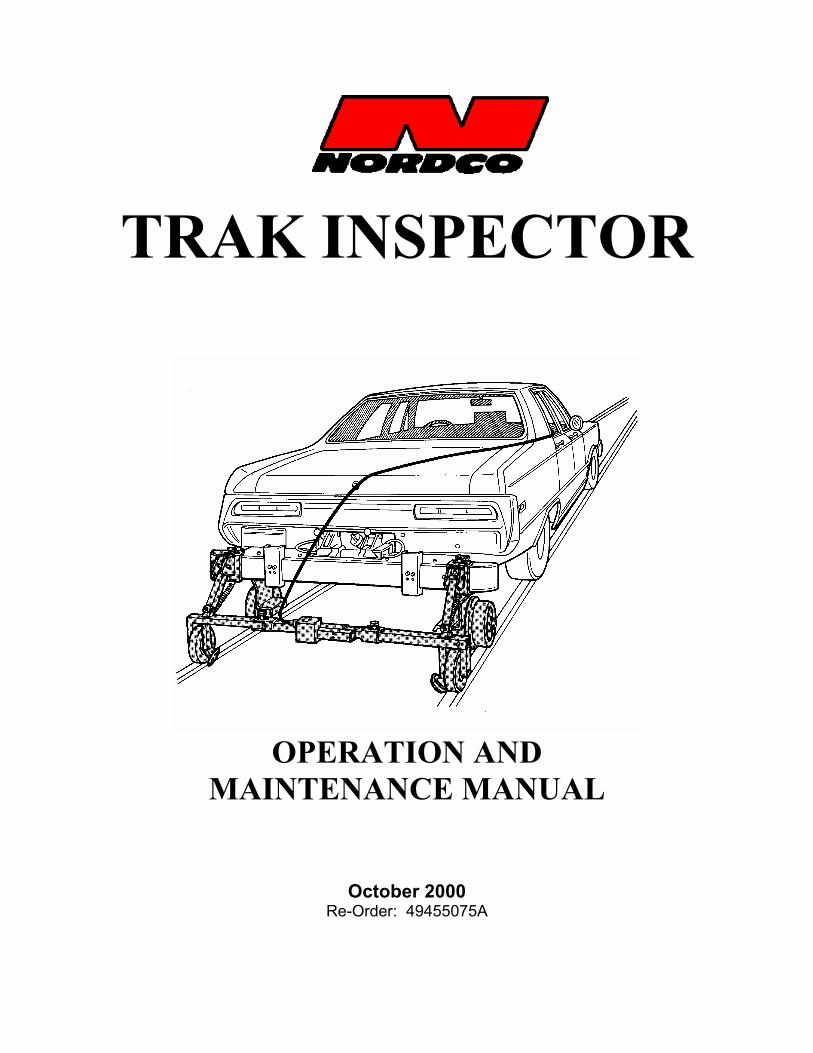
TRAK INSPECTOR
OPERATION AND
MAINTENANCE MANUAL
October 2000 Re-Order: 49455075A


This manual is a guide for the operation and routine maintenance of a NORDCO Railroad Maintenance Machine. It covers product technical information, basic operating and maintenance procedures, and safety information and is provided for use by the qualified personnel who will supervise, operate or service the equipment described herein. Measurements in this manual are given in both metric and customary U.S. unit equivalents. Personnel responsible for the operation and maintenance of this equipment should thoroughly study the manual before commencing operation or maintenance procedures.
This manual should be considered a permanent part of your machine and should remain with the machine at all times. Additional copies of this manual are available either as a part (Operation Manual only) or a whole (operation and parts manual), at a nominal cost, through our Part Sales Department. Additional service information, parts, and application information is available through these Nordco product support resources:
NORDCO Sales: Milwaukee, Wisconsin (414) 766-2180
[email protected] NORDCO Parts: Milwaukee, Wisconsin
1-800-647-1724 [email protected]
Oshawa, Ontario, Canada (905) 579-4058, Ext. 224 [email protected]
NORDCO Service: 1-800-445-9258
[email protected] We ask that if you have any comments or suggestions about this manual, let us hear from you. We are here to be of service to you, our customers. Direct your comments and inquiries to:
Technical Documentation Department
NORDCO Inc. 245 W. Forest Hill Avenue
Oak Creek, WI 53154

HAZARDOUS MATERIAL DATA In an effort to provide information necessary for your employee safety training program and to meet the requirements of OSHA Hazard Communication Standard 1910.1200, we have OSHA Form 20 Safety Data Sheets available that cover the material contained in this machine. If you are interested in receiving this information, please refer to the Name, model, and Serial Number of your machine when calling or writing, and direct your inquiries to:
Vice-President of Operations
NORDCO Inc. 245 W. Forest Hill Avenue
Oak Creek, WI 53154
Fax: (414) 766-2299 Phone: (414) 766-2288

TRAK INSPECTOR CONTENTS
10/00 (4945-5075A) i Contents
TABLE OF CONTENTS SAFETY .............................................................................................................................................................. 1
Follow Safety Instructions ............................................................................................................................. 1 Safety Alert Symbol Definitions ..................................................................................................................... 1 General Safety Tips....................................................................................................................................... 2 Safety During Work .................................................................................................................................. 2 Safety During Travel................................................................................................................................. 2 Safety During Maintenance ...................................................................................................................... 2 Safety Alerts .................................................................................................................................................. 3 Lockout/Tagout Procedures .......................................................................................................................... 5
GENERAL INFORMATION................................................................................................................................. 7 About the Optional Recorder ..................................................................................................................... 7
Machine Specifications.................................................................................................................................. 7 Parts Ordering Information ............................................................................................................................ 8
OPERATION
BEFORE OPERATION ....................................................................................................................................... 9
Trak Inspector Controls - Description and Art ............................................................................................. 10 MACHINE SET-UP............................................................................................................................................ 14
Bumper Modification and Installation ..................................................................................................... 14 Mounting...................................................................................................................................................... 15
Electrical Connections.............................................................................................................................. 17 Optional Recorder - Loading Paper......................................................................................................... 18 PRE- OPERATION............................................................................................................................................ 19 MACHINE OPERATION.................................................................................................................................... 19 AFTER OPERATION ........................................................................................................................................ 20
Repacking Inspector into Case ................................................................................................................... 21
MAINTENANCE AND SERVICE GENERAL ......................................................................................................................................................... 23 MAINTENANCE INSTRUCTIONS .................................................................................................................... 25 PARTS SHEETS Mechanical Assembly (Without Recorder) ............................................................................................61-01-1 Mechanical Assembly (With Recorder)..................................................................................................61-01-2 Electrical Assembly (Without Recorder, S/N _______) ........................................................................61-02-1 Electrical Assembly (Without Recorder, S/N _______) ..................................................................... 61-02-1A Electrical Assembly (With Recorder, S/N _______)..............................................................................61-02-2 Electrical Schematic without Recorder .................................................................................................61-60-1 Electrical Schematic with Recorder.......................................................................................................61-60-2

TRAK INSPECTOR SAFETY
10/00 (4945-5075A) Safety, Page 1
SAFETY Please read and comply with all of the safety precautions in this manual BEFORE operating this machine. GENERAL DO NOT use this machine for machine operations other than for which it was intended. NORDCO is not responsible for any modifications made without authorization or written approval. Replace all NORDCO and OEM parts with genuine NORDCO or OEM parts. Use of non-OEM parts could compromise the safety of your machine. FOLLOW SAFETY INSTRUCTIONS Carefully read all safety messages in this manual. Learn how to operate the machine and how to use controls properly. Do not let anyone operate this machine without instruction.
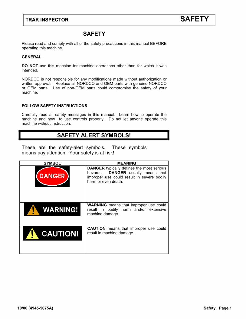
SAFETY ALERT SYMBOLS! These are the safety-alert symbols. These symbols means pay attention! Your safety is at risk!
SYMBOL MEANING
DANGER typically defines the most serious hazards. DANGER usually means that improper use could result in severe bodily harm or even death.
WARNING means that improper use could result in bodily harm and/or extensive machine damage.
CAUTION means that improper use could result in machine damage.
TRAK INSPECTOR SAFETY
10/00 (4945-5075A) Safety, Page 2
GENERAL SAFETY TIPS Only trained and authorized personnel should be allowed to operate this machine. In addition, all personnel should be aware of the safety concerns and their individual responsibilities prior to working this machine. SAFETY DURING WORK To prevent personal injury or damage to the machine, it is highly recommended to: 1. Make certain that no one is in the path of your vehicle. Before moving this
machine make certain that all personnel have left the area before moving this machine.
2. Strong rains, fog, and extremely dusty and blowing conditions can obscure
visibility in your work area. Wait for weather to improve before continuing work.
3. Anyone standing near the machine is at risk of being injured. Make certain
they keep away from any moving assembly during working operations. SAFETY DURING TRAVEL Traveling with this machine requires all steps listed above, in addition: 1. Always make certain that lockups provided on this machine are free of debris
or grease and are in place prior to travel. 2. Operate the machine carefully when bad weather conditions exist. Maintain a
distance between machines that will allow you room to stop. 3. Strong rains, fog, and extremely dusty and blowing conditions can obscure
visibility in your area. Wait for weather situation to improve before continuing travel.
4. Anyone standing near the machine is at risk of being injured. Make certain
they keep away from the machine during travel operations. SAFETY DURING MAINTENANCE Alert others in the area that service or maintenance is being performed on this machine. Become familiar with, and use, your company’s lockout/tagout procedures when performing maintenance on this machine. See LOCKOUT/TAGOUT REQUIREMENTS later in this Safety Section for a chart on energy sources located on this machine.
TRAK INSPECTOR SAFETY
10/00 (4945-5075A) Safety, Page 3
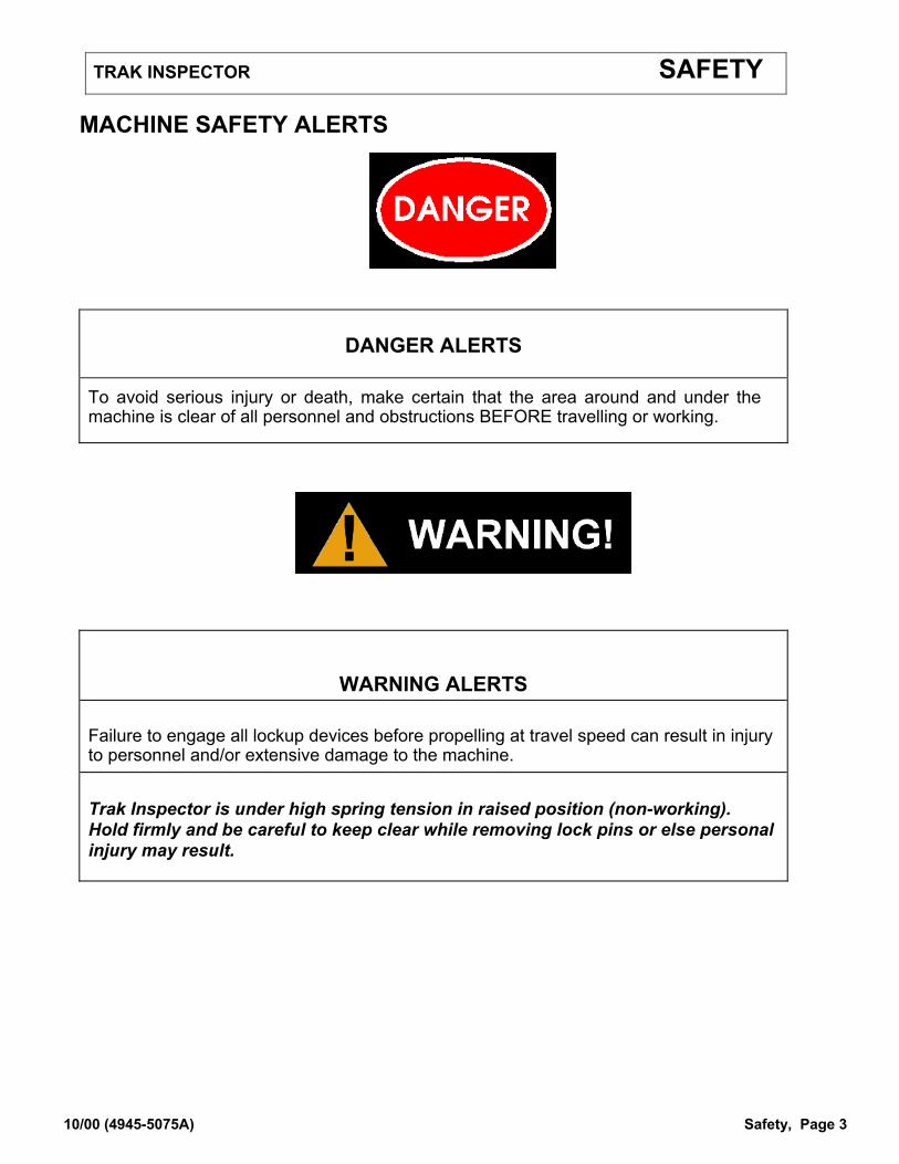
MACHINE SAFETY ALERTS
DANGER ALERTS
To avoid serious injury or death, make certain that the area around and under the machine is clear of all personnel and obstructions BEFORE travelling or working.
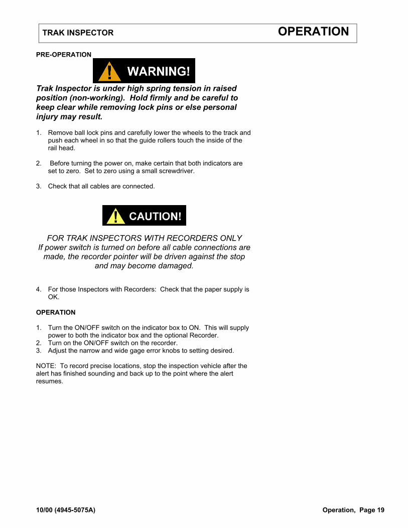
WARNING ALERTS Failure to engage all lockup devices before propelling at travel speed can result in injury to personnel and/or extensive damage to the machine. Trak Inspector is under high spring tension in raised position (non-working). Hold firmly and be careful to keep clear while removing lock pins or else personal injury may result.
TRAK INSPECTOR SAFETY
10/00 (4945-5075A) Safety, Page 4
MACHINE SAFETY ALERTS
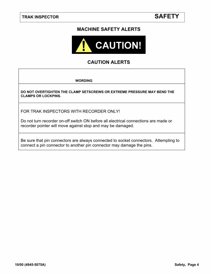
CAUTION ALERTS
WORDING DO NOT OVERTIGHTEN THE CLAMP SETSCREWS OR EXTREME PRESSURE MAY BEND THE CLAMPS OR LOCKPINS. FOR TRAK INSPECTORS WITH RECORDER ONLY! Do not turn recorder on-off switch ON before all electrical connections are made or recorder pointer will move against stop and may be damaged. Be sure that pin connectors are always connected to socket connectors. Attempting to connect a pin connector to another pin connector may damage the pins.

TRAK INSPECTOR SAFETY
10/00 (4945-5075A) Safety, Page 5
LOCKOUT AND/OR TAGOUT PROCEDURES It is your company’s responsibility to develop Lockout/Tagout Procedures, train you in their proper and safe use, and to periodically inspect your work area to verify that you are complying with the procedures. Lockout/Tagout Procedures must be followed! This machine is completely locked out when the ignition switch and battery disconnect switch have been turned to the “OFF” position and their respective covers closed and locked. HOWEVER, some energy is stored in the hydraulic components of this machine; and these must be relieved of pressure prior to service and maintenance. NORDCO has provided the means to lockout this machine. NORDCO cannot be held responsible for injury caused by failure to comply with your company’s Lockout/Tagout Procedures. ENERGY SOURCES The list on the following pages provides information on energy sources located on this machine and instructions for inserting manual lockups, if applicable. It is your company’s responsibility to incorporate these instructions into their Lockout/Tagout Procedures. LOCKOUT/TAGOUT – PROCEDURES
When servicing or performing maintenance on:
Energy Source to be locked out:
Use this procedure:
Electrical System
Electrical
1) Turn off the Optional Recorder. 2) Turn off the Indicator Box. 3) Unplug the power cord from the Lighter Plug in the vehicle. This will cut off electrical power supply to the machine.
TRAK INSPECTOR SAFETY
10/00 (4945-5075A) Safety, Page 6
THIS PAGE LEFT BLANK INTENTIONALLY

TRAK INSPECTOR GENERAL
10/00 (4945-5075A) General, Page 7
GENERAL This manual contains information for the Trak Inspector manufactured by NORDCO INC., Milwaukee, Wisconsin. Information is provided in this manual for operation and maintenance of the machine. Information regarding operation and maintenance of OEM parts not of NORDCO manufacture can be found at the back of this manual, behind the tab marked “Component Data”, if applicable. Become familiar with all safety instructions, controls and instruments before operating this machine. Follow all instructions carefully. About the Optional Recorder The Optional Recorder is no longer available as a repair part item, nor as an option on this machine. It is included in the manual for reference to those who have purchased the Trak Inspector with Recorder in the past. SPECIFICATIONS GENERAL Vehicle Speed......................................................................................................................................0-10 mph Power Requirements ....................................................................................... 12-VDC from inspection vehicle Weight pounds INDICATOR BOX Reading Range Gage.......................................................................................1/2 inch () (narrow) to 1-1/2 inch () (wide) Elevation...............................................................................................................................0-6 inches() Accuracy Gage.......................................................................................................................................1/16 Inch() Elevation................................................................................................................................1/16 Inch () Fuse .......................................................................................................................................... 1/2 Amp RECORDER Paper Type ............................................................. Pressure Sensitive, black base with reflective white layer Style ................................................................................................................................................WAA Scale Markings Elevation........................................................................................................................... .2 inches Gage............................................................................................................................... .05 inches Length................................................................................................................................. 756 inches () Speed ........................................................................................................ Proportional to Vehicle Speed Capacity .................................................................................15.75 miles of track or 95 minutes at 10 mph Fuse ........................................................................................................................................... 1A 3AG All rights reserved. In view of the constant improvements to our equipment, the specification data and other technical information included in this manual are subject to change. No part of this manual may be reproduced in any form or by any means without our written permission.
TRAK INSPECTOR GENERAL
10/00 (4945-5075A) General, Page 8
INSTRUCTIONS FOR ORDERING REPAIR PARTS The parts sheets identify all parts of your machine in three ways: 1) by part number; 2) by part name; and 3) by appearance as shown on the exploded view drawing. The exploded view drawings have item numbers which are then cross-referenced to the list following the drawing. (Example, Item 17 on the drawing will be Item 17 on the list.) You can order parts two ways, as individual parts or as one item of many in an assembly. Due to possible design changes some assemblies may have changed. Before you order, contact the Parts Sales Department to verify the items on the assembly. If you have any questions, the personnel in the Parts Sales Department will be happy to assist you in your ordering. For your convenience, we now accept MasterCharge and Visa as a method of payment. When ordering parts, always include the following information:
1. The Machine Make and Model. 2. The serial number of the machine. 3. The exact quantities of assemblies or parts desired. Please identify these parts by part
number and name. 4. Specify the method of shipment desired.
To reduce delays, please avoid references to other matters in letters forwarded primarily for ordering repair parts. Forward all repair orders to:
NORDCO PARTS SALES DEPARTMENT P.O. BOX 1562
MILWAUKEE, WI 53201
Call in your orders to:
NORDCO PARTS SALES DEPARTMENT Telephone: (414) 769-4607 Telephone: (414) 769-4608 Telephone: (800) 647-1724
Fax: (414) 769-2140 e-mail: [email protected]
GOODS RETURNED FROM CUSTOMER (GRFC) When returning goods, you are to call the above number and explain the reasons for returning the goods. They will issue a GRFC number that you are to use for all future correspondence on the return including the package with the item being returned. This will speed up the exchange or credit process. GRFC’s are also issued by the Service Manager.

TRAK INSPECTOR OPERATION
10/00 (4945-5075A) Operation, Page 9
Before operating this machine, read and understand the Safety Section of this Manual.
BEFORE OPERATION
GENERAL The Trak Inspector is a mechanical/electrical system specifically designed for use with railway inspection vehicles to measure and record variation in gage width and rail elevation. The mechanical part of the system consists of a frame with clamps that attach to the bumper of the inspection vehicle and with wheels and guide rollers that ride along the track. An indicator box, attached by cable to the frame and powered by the inspection vehicles lighter plug, receives impulses from a phototransistor mounted on the left wheel, displays gage and elevation readings with an accuracy of 1/16-inch () and sounds an alarm when gage set limits are exceeded. The indicator box varies according to age of machine and/or whether or not your machine includes a recorder. See following pages for detailed function of box(es). RECORDER (Optional, No Longer Available) An optional 12-VDC recorder prints out a continuous paper record of gage and elevation readings. A stylus marks the paper by pushing aside the outer white layer of paper and leaving the inner black layer. Notes can be made on the paper through the access window.
TRAK INSPECTOR OPERATION
10/00 (4945-5075A) Operation, Page 10
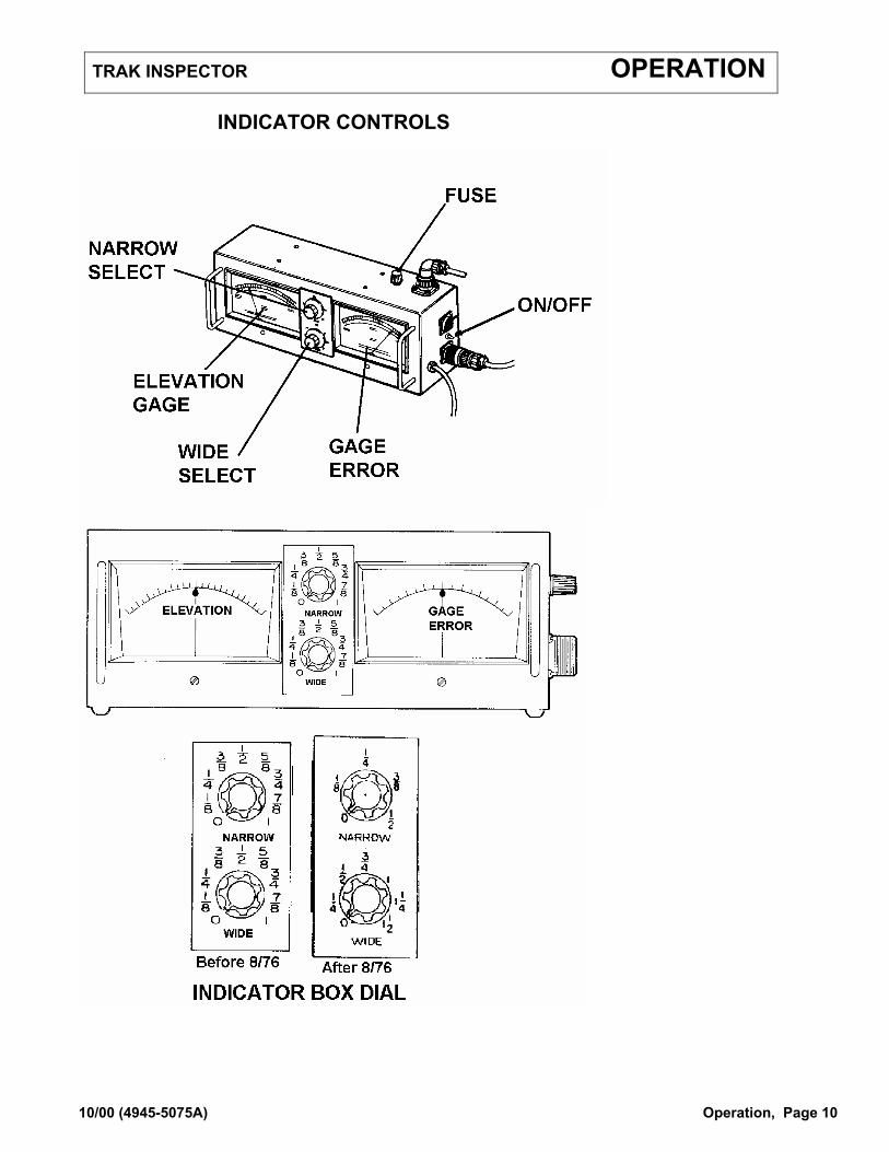
INDICATOR CONTROLS

TRAK INSPECTOR OPERATION
10/00 (4945-5075A) Operation, Page 11
ITEM CONTROLS On/Off Switch
Without Recorder
With Recorder
The On/OFF switch opens or breaks the circuit to the vehicle's electrical system. To avoid any unnecessary drain on the vehicle battery, always place the switch in the OFF position when the engine is not running. Conversely, the switch must always be in the ON position when track inspection is in progress. NOTE: Also provides power to the Inspector Assembly traveling behind inspection vehicle. On/Off Switch is located on power cord going into box. On/Off Switch is located between cables on side of Indicator Box
Elevation Gage Meter The elevation meter is divided into two halves. The right side of the meter indicates the height of the right hand rail in relation to the left hand rail. The left hand side of the meter indicates the height of the left hand rail in relation to the right hand rail. The meter is calibrated from "0", at the center of the meter, to a 6" full scale reading at the left and right sides of the meter. Between "0" and the full scale reading of 6", the meter is divided into individual inches and each inch is divided into eighths.
Gage Error Meter
Before 8/76
After 8/76
The gage error meter is divided into two halves. The right side of the meter indicates the amount the two rails are WIDER THAN GAGE and the left side of the meter indicates the amount the two rails are LESS (NARROWER) THAN GAGE. An alarm is sounded when the gage error meter tolerance has been exceeded. Tolerance is set by using the NARROW and WIDE adjustment knobs outlined below. The meter is calibrated from "0" at the center of the meter to a full scale reading of 1" at the left and right sides of the meter. The meter is divided into eighths and each eighth is divided into sixteenths. The meter is calibrated from "0" at the left center of the meter to a full scale reading of 1/2" at the left side and 1-1/2" at the right side of the meter. The meter is divided into eighths and each eighth is divided into sixteenths.
TRAK INSPECTOR OPERATION
10/00 (4945-5075A) Operation, Page 12
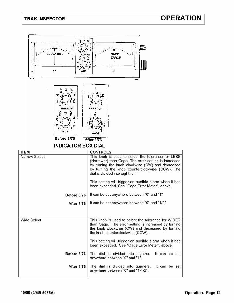
ITEM CONTROLS Narrow Select
Before 8/76
After 8/76
This knob is used to select the tolerance for LESS (Narrower) than Gage. The error setting is increased by turning the knob clockwise (CW) and decreased by turning the knob counterclockwise (CCW). The dial is divided into eighths. This setting will trigger an audible alarm when it has been exceeded. See "Gage Error Meter", above. It can be set anywhere between "0" and "1". It can be set anywhere between "0" and "1/2".
Wide Select
Before 8/76
After 8/76
This knob is used to select the tolerance for WIDER than Gage. The error setting is increased by turning the knob clockwise (CW) and decreased by turning the knob counterclockwise (CCW). This setting will trigger an audible alarm when it has been exceeded. See "Gage Error Meter", above. The dial is divided into eighths. It can be set anywhere between "0" and "1". The dial is divided into quarters. It can be set anywhere between "0" and "1-1/2".

TRAK INSPECTOR OPERATION
10/00 (4945-5075A) Operation, Page 13
RECORDER CONTROLS
ITEM CONTROLS On/Off Switch Turns Recorder On/Off. NOTE: This will only work if
the power to the Indicator Box has been turned on.
Chart Advance Wheel Advances the paper feed in the recorder.
See "Setup for the Optional Recorder" later in this manual for descriptions and diagrams of the inside of the recorder.
TRAK INSPECTOR OPERATION
10/00 (4945-5075A) Operation, Page 14
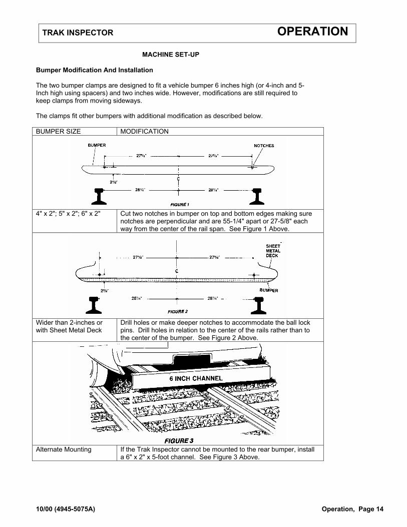
MACHINE SET-UP Bumper Modification And Installation The two bumper clamps are designed to fit a vehicle bumper 6 inches high (or 4-inch and 5-Inch high using spacers) and two inches wide. However, modifications are still required to keep clamps from moving sideways. The clamps fit other bumpers with additional modification as described below. BUMPER SIZE MODIFICATION
4" x 2"; 5" x 2"; 6" x 2" Cut two notches in bumper on top and bottom edges making sure
notches are perpendicular and are 55-1/4" apart or 27-5/8" each way from the center of the rail span. See Figure 1 Above.
Wider than 2-inches or with Sheet Metal Deck
Drill holes or make deeper notches to accommodate the ball lock pins. Drill holes in relation to the center of the rails rather than to the center of the bumper. See Figure 2 Above.
Alternate Mounting If the Trak Inspector cannot be mounted to the rear bumper, install
a 6" x 2" x 5-foot channel. See Figure 3 Above.
TRAK INSPECTOR OPERATION
10/00 (4945-5075A) Operation, Page 15
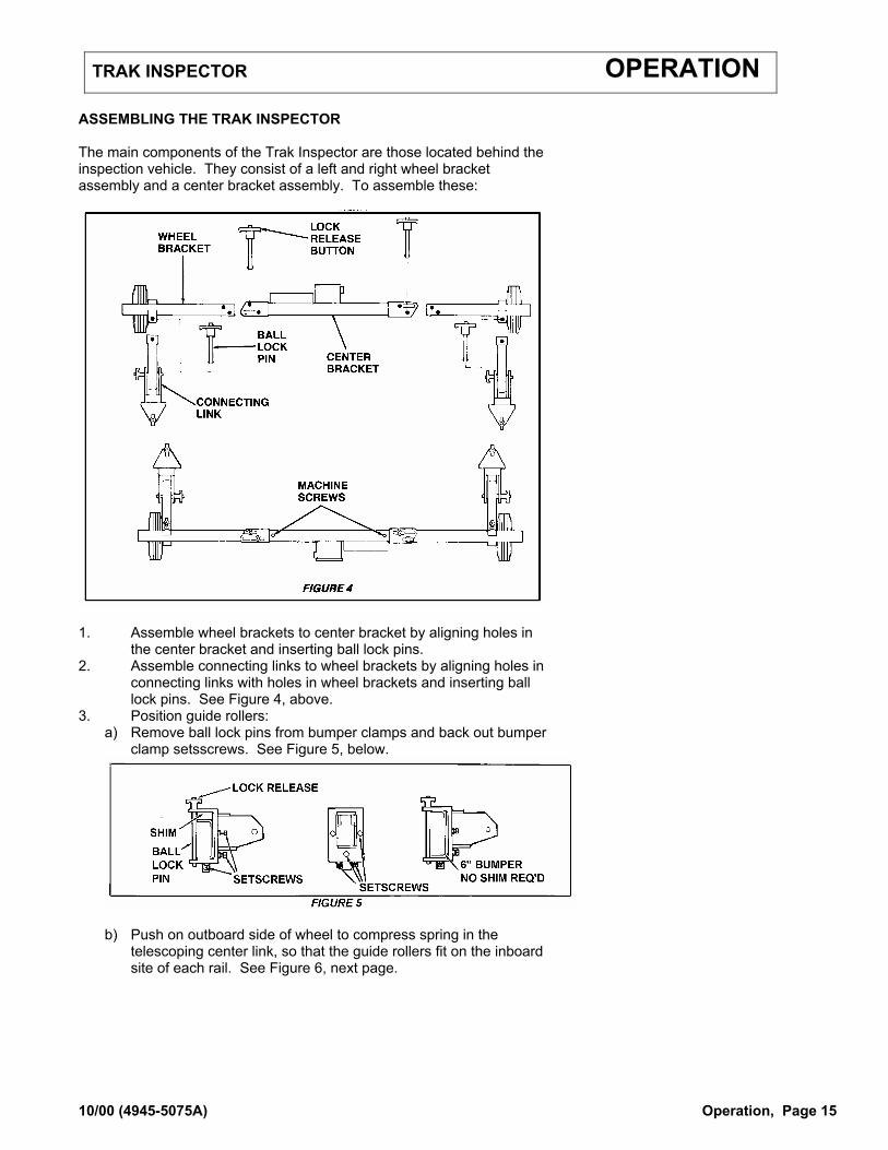
ASSEMBLING THE TRAK INSPECTOR The main components of the Trak Inspector are those located behind the inspection vehicle. They consist of a left and right wheel bracket assembly and a center bracket assembly. To assemble these:
1. Assemble wheel brackets to center bracket by aligning holes in
the center bracket and inserting ball lock pins. 2. Assemble connecting links to wheel brackets by aligning holes in
connecting links with holes in wheel brackets and inserting ball lock pins. See Figure 4, above.
3. Position guide rollers: a) Remove ball lock pins from bumper clamps and back out bumper
clamp setsscrews. See Figure 5, below.
b) Push on outboard side of wheel to compress spring in the
telescoping center link, so that the guide rollers fit on the inboard site of each rail. See Figure 6, next page.

TRAK INSPECTOR OPERATION
10/00 (4945-5075A) Operation, Page 16
4. Install clamps:
(a) Insert a ball lock pin in each clamp. (b) Insert a two inch spacer (on a 4" bumper) or a one-inch spacer
(on a 5-inch bumper between the clamp and the top of the bumper. See Figure 5.
(c) Tighten setscrews so that the clamps fit snugly on the bumper
without any free play and so that clamps can be installed or removed by using only the lock ball pins.
5. Check that wheel bracket is vertical in relation to the rail so that elevation readings will be accurate. Adjust by removing the bolt, changing the length of the telescoping link, and reinstalling the bolt and tightening the nut and locknut.
DO NOT OVERTIGHTEN THE CLAMP SETSCREWS OR EXTREME PRESSURE MAY BEND THE CLAMPS OR LOCKPINS.
TRAK INSPECTOR OPERATION
10/00 (4945-5075A) Operation, Page 17
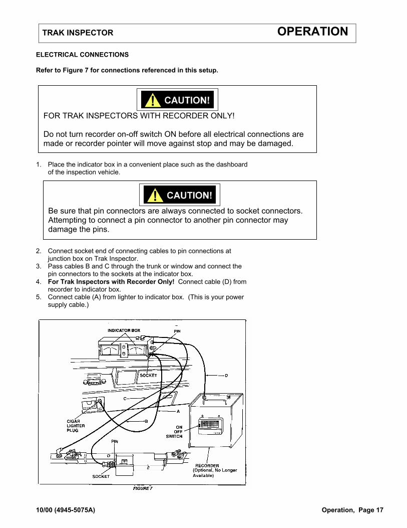
ELECTRICAL CONNECTIONS Refer to Figure 7 for connections referenced in this setup.
1. Place the indicator box in a convenient place such as the dashboard
of the inspection vehicle.
2. Connect socket end of connecting cables to pin connections at
junction box on Trak Inspector. 3. Pass cables B and C through the trunk or window and connect the
pin connectors to the sockets at the indicator box. 4. For Trak Inspectors with Recorder Only! Connect cable (D) from
recorder to indicator box. 5. Connect cable (A) from lighter to indicator box. (This is your power
supply cable.)
FOR TRAK INSPECTORS WITH RECORDER ONLY! Do not turn recorder on-off switch ON before all electrical connections are made or recorder pointer will move against stop and may be damaged.
Be sure that pin connectors are always connected to socket connectors. Attempting to connect a pin connector to another pin connector may damage the pins.
TRAK INSPECTOR OPERATION
10/00 (4945-5075A) Operation, Page 18
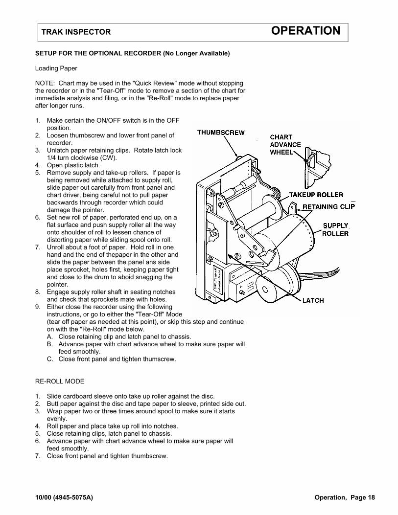
SETUP FOR THE OPTIONAL RECORDER (No Longer Available) Loading Paper NOTE: Chart may be used in the "Quick Review" mode without stopping the recorder or in the "Tear-Off" mode to remove a section of the chart for immediate analysis and filing, or in the "Re-Roll" mode to replace paper after longer runs. 1. Make certain the ON/OFF switch is in the OFF
position. 2. Loosen thumbscrew and lower front panel of
recorder. 3. Unlatch paper retaining clips. Rotate latch lock
1/4 turn clockwise (CW). 4. Open plastic latch. 5. Remove supply and take-up rollers. If paper is
being removed while attached to supply roll, slide paper out carefully from front panel and chart driver, being careful not to pull paper backwards through recorder which could damage the pointer.
6. Set new roll of paper, perforated end up, on a flat surface and push supply roller all the way onto shoulder of roll to lessen chance of distorting paper while sliding spool onto roll.
7. Unroll about a foot of paper. Hold roll in one hand and the end of thepaper in the other and slide the paper between the panel ans side place sprocket, holes first, keeping paper tight and close to the drum to aboid snagging the pointer.
8. Engage supply roller shaft in seating notches and check that sprockets mate with holes.
9. Either close the recorder using the following instructions, or go to either the "Tear-Off" Mode (tear off paper as needed at this point), or skip this step and continue on with the "Re-Roll" mode below. A. Close retaining clip and latch panel to chassis. B. Advance paper with chart advance wheel to make sure paper will
feed smoothly. C. Close front panel and tighten thumscrew.
RE-ROLL MODE 1. Slide cardboard sleeve onto take up roller against the disc. 2. Butt paper against the disc and tape paper to sleeve, printed side out. 3. Wrap paper two or three times around spool to make sure it starts
evenly. 4. Roll paper and place take up roll into notches. 5. Close retaining clips, latch panel to chassis. 6. Advance paper with chart advance wheel to make sure paper will
feed smoothly. 7. Close front panel and tighten thumbscrew.
TRAK INSPECTOR OPERATION
10/00 (4945-5075A) Operation, Page 19
PRE-OPERATION
Trak Inspector is under high spring tension in raised position (non-working). Hold firmly and be careful to keep clear while removing lock pins or else personal injury may result. 1. Remove ball lock pins and carefully lower the wheels to the track and
push each wheel in so that the guide rollers touch the inside of the rail head.
2. Before turning the power on, make certain that both indicators are
set to zero. Set to zero using a small screwdriver. 3. Check that all cables are connected.
FOR TRAK INSPECTORS WITH RECORDERS ONLY If power switch is turned on before all cable connections are
made, the recorder pointer will be driven against the stop and may become damaged.
4. For those Inspectors with Recorders: Check that the paper supply is
OK. OPERATION 1. Turn the ON/OFF switch on the indicator box to ON. This will supply
power to both the indicator box and the optional Recorder. 2. Turn on the ON/OFF switch on the recorder. 3. Adjust the narrow and wide gage error knobs to setting desired. NOTE: To record precise locations, stop the inspection vehicle after the alert has finished sounding and back up to the point where the alert resumes.

TRAK INSPECTOR OPERATION
10/00 (4945-5075A) Operation, Page 20
AFTER OPERATION When inspection is temporarily finished or you are leaving the track, turn off the indicator box (and the optional recorder), raise the trak inspector to carrying position by removing the two ball lock pins, raising the wheels, and inserting the pins under the telescopic link. If you are ending inspection, use the following procedures for disassembly, storage, and transport of the Trak Inspector: 1. Make certain the indicator box and optional recorder are turned off. 2. Disconnect all electrical cables. 3. Detach unit from bumper by removing the ball lock pins from the
bumper clamps. (Insert lockpins into holes provided to prevent losing the pins).
4. Remove ball lock pins that attach connecting links to wheel brackets and separate the assemblies.
5. Remove ball lock pins that attach wheel brackets to center bracket and separate the assemblies.
6. Place individual assemblies in carrying case as indicated on the drawing on the next page.

TRAK INSPECTOR OPERATION
10/00 (4945-5075A) Operation, Page 21
1. Insert the Indicator box into the storage slot provided. 2. Insert the Outer/Inner Bracket Assembly (do not separate) 3. Insert the left bumper clamp arm bracket. 4. Insert the right bumper clamp arm bracket. 5. Insert the left wheel bracket assembly. 6. Insert the right wheel bracket assembly. 7. Insert the power cord (Indicator box to junction box on Inspector) NOTE: The carrying case is not designed to hold the recorder box. This should be packed separately.


TRAK INSPECTOR MAINTENANCE
10/00 (4945-5075A) Maintenance, Page 23
NORDCO'S SERVICE NETWORK Need assistance? It's only a phone call away! If you experience problems, contact your original sales representative first, he is the one listed on the front page of this manual. If you cannot reach him, we suggest that you contact the representative closest to your work area BEFORE calling NORDCO's Service Manager. See map on the next page for the alternate representative closest to your work area. REQUESTING ASSISTANCE If you have any questions regarding maintenance and service on this machine, the process will be faster if you have the following information in hand before calling: 1. The Machine Name: Trak Inspector A or B 2. The Type of Machine: With or Without Recorder 3. The Serial Number: (Located on center bracket) SERVICE NETWORK
No. Representative Phone Number 1. Nordco Service Manager 1-800-445-9258 or (414) 769-4603 2. Russell Railway Supply (612) 835-5125 3. or 4 James H. Lynde (913) 648-7379 5. North American Equipment Company (606) 885-3353 6. Dwayne Lambing (770) 424-0401 7. North American Equipment Company (716) 675-2040 8. North American Equipment Ltd. (Canada) (905) 628-9997 International: American Equipment (561) 997-2080

TRAK INSPECTOR MAINTENANCE
10/00 (4945-5075A) Maintenance, Page 24
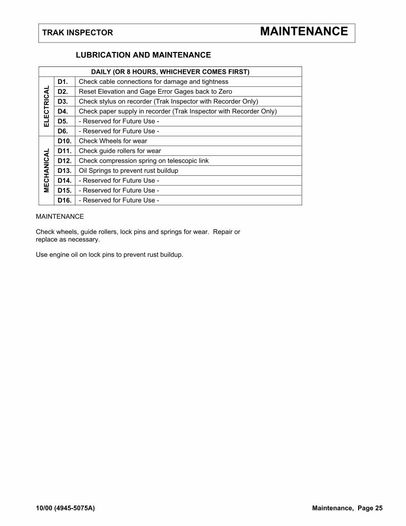
LUBRICATION AND MAINTENANCE Service points on this machine (adjustments, inspections, lubrication, etc.) are indicated on the following illustration. The items listed are preceded by a “D1, W1, M1, Q1 and A1" designation. These points service interval (D=Daily, W=Weekly, M=Monthly, Q=Quarterly and A=Annually) for this point of the machine. Maintenance instructions are given for each and are separated by Service Interval Designation. NOTE: Engine lubrication and maintenance instructions are included in this manual as a reference tool only. It is NOT meant to substitute for the instructions given in the Engine Manufacturer’s Manual. If you no longer have a manual, contact Nordco Parts Sales for the local distributor of your engine.
TRAK INSPECTOR MAINTENANCE
10/00 (4945-5075A) Maintenance, Page 25
LUBRICATION AND MAINTENANCE
DAILY (OR 8 HOURS, WHICHEVER COMES FIRST) D1. Check cable connections for damage and tightness D2. Reset Elevation and Gage Error Gages back to Zero D3. Check stylus on recorder (Trak Inspector with Recorder Only) D4. Check paper supply in recorder (Trak Inspector with Recorder Only) D5. - Reserved for Future Use - EL
ECTR
ICA
L
D6. - Reserved for Future Use - D10. Check Wheels for wear D11. Check guide rollers for wear D12. Check compression spring on telescopic link D13. Oil Springs to prevent rust buildup D14. - Reserved for Future Use - D15. - Reserved for Future Use - M
ECH
AN
ICA
L
D16. - Reserved for Future Use - MAINTENANCE Check wheels, guide rollers, lock pins and springs for wear. Repair or replace as necessary. Use engine oil on lock pins to prevent rust buildup.