Embed Size (px)
Citation preview
Trajectory Controller for a Bebop QuadcopterIlya Semenov
University of [email protected]
Tim KurtiakUniversity of Maryland
Abstract—This report presents the implementation and resultsof a closed loop trajectory controller for a Parrot Bebop quad-copter. The controller was built as an outer loop to expand uponthe Bebop’s attitude and position controller. Three trajectories,Helix, Diamond, and Stairstep were executed.
I. PROBLEM STATEMENT
This project aims to implement an outer loop trajectory con-troller for the Parot Bebod quadcopter using Robot OperatingSystem. In addition, the telemetry is visualized and comparedto the desired trajectory using VICON data plotted in RVIZ.
II. TRAJECTORY PARAMETERIZATION
In order to implement a trajectory controller, we mustfirst generate a feasible trajectory. Three trajectories wereconsidered in this project: a Diamond, a Helix, and a Staircasedescribed in Figure 1 2 , and 3
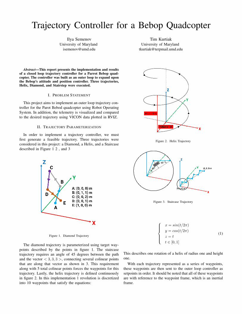
Figure 1. Diamond Trajectory
The diamond trajectory is parameterized using target way-points described by the points in figure 1. The staircasetrajectory requires an angle of 45 degrees between the pathand the vector < 3, 3, 3 >, connecting several colinear pointsthat are along that vector as shown in 3. This requirementalong with 5 total colinear points forces the waypoints for thistrajectory. Lastly, the helix trajectory is defined continuouslyin figure 2. In this implementation 1 revolution is discretizedinto 10 waypoints that satisfy the equations:
Figure 2. Helix Trajectory
Figure 3. Staircase Trajectory
x = sin(t/2π)
y = cos(t/2π)
z = t
t ∈ [0, 1]
(1)
This describes one rotation of a helix of radius one and heightone.
With each trajectory represented as a series of waypoints,these waypoints are then sent to the outer loop controller assetpoints in order. It should be noted that all of these waypointsare with reference to the waypoint frame, which is an inertialframe.

III. DESIGN OF OUTER LOOP CONTROLLER
The outer loop controller must steer the quadcopter to adesired setpoint while taking feedback from the quadcopter’sposition sensor. This is achieved through a closed loop trackercontroller based on position and velocity error.
First it must be noted that the Bebop drone assigns aninertial frame upon being turned on, and all odometry readingsare collected relative to that frame. However, the commandssent to the drone are in the body frame and waypoints aredescribed in the waypoint frame. An open loop controller cansuffice with a series of commands set purely in the body frame,but to use odometry information as feedback a rotation mustbe preformed.
The orientation of the body frame B is encoded in a unitquaternion. Let qBI be the unit quaternion that describesthe rotation to the body frame from the inertial frame I .Then a vector vI in the inertial frame is made into a non-unit quaternion qvI = [0, vI ] and transformed into non-unitquaternion qvB = [0, v̄B ] via:
qvB = qBI ⊗ qv ⊗ qBI−1 (2)
Where ⊗ denotes a quaternion multiplication. Vector v̄Bis a representation of vI in the inertial frame. However, thetranslation of the body frame needs to be taken into accountbefore the final vector vB is constructed.
It should be noted that qBI−1 = qIB and the rotation of
a vector from the body frame into the inertial is the sameprocess as above.
Way points are described in the waypoint frame W whichis a fixed frame equal to the body frame at a user specifiedtime after takeoff with orientation qW I and displacementrW I represented in the inertial frame. Let a waypoint in thewaypoint frame wW be given. The controller must first rotatethe waypoint into the inertial frame via vector rotation byqIW , resulting in w̄I . Then the location of the waypoint inthe inertial frame is wI = w̄I + rWI .
The error vector in the inertial frame is eI = wI − rBI
where rBI is the current displacement of the body frameorigin represented in the inertial frame.
The error vector is rotated by qBI to result in eB and itis a function of time t. Translation is taken into account pre-rotation.
Given that the waypoint was assigned at time t = t0 thenthe control command u at time t is given:
u = Kp. ∗ eB +Ki. ∗∫ t
t0
eBdt−Kd. ∗eBdt
(3)
Where .∗ represents element wise multiplication andKp,Ki,Kd are gain vectors.
IV. IMPLEMENTATION
The implementation is structurally simple, but many testswere carried out leading up to the final point. A python scriptfunctions as a node with several publishers and subscribers.A subscriber to topic bebop/odom receives odometry data and
saves it to global variables. A publisher to bebop/takeoff sendsan Empty message for the vehicle to take off. After a pause,the odometry data is saved as a separate global variable, thisis now the basis of the waypoint frame.
A function moveto() was created that is passed waypointcoordinates (in the waypoint frame) calculates the inertialframe representation of the way point, and proceeds to executethe loop culminated by equation 3. The output u is sent as aTwist message to topic bebop/cmd vel. The components of uare placed in the linear portion of a Twist message only, thereis no yaw in this system at this time.
The waypoints that are passed to moveto() are the onlything that changes between scripts for different trajectories.The gains are also subject to change.
One major challenge of this project was the lack of phys-ical intuition regarding publishing Twist messages to thebebop/cmd vel topic. The combination of values and timedelay post command change the behavior of the vehicle uponexecution considerably. Additionally, the responses in thex,y,z directions are not consistent amongst themselves. Thesechallenges were found upon initial attempts for an open loopcontroller, and where the primary driving factor for closedloop.
Another issue that was identified late and not rectified fullywas the uncertainty in odometry data given by the vehicle.Especially at low altitude this data would be very erroneous,and would build up error over longer flights.
Special thanks to Abhishek for advice throughout develop-ment and for lending a hand during the demo, Animesh forhelp during the demo, and Derek Thompson for providing atemplate for RVIZ.
V. RESULTS
Result videos are posted here:helix https://youtu.be/0wlfIFKXbyQ dia-
mond https://youtu.be/e3qxK9pr8Astairhttps ://youtu.be/D381V yEMNko
Despite the multiple crashes that occurred during the demo,there is reason to be optimistic about the performance of theBebop. Notably, it tracked it’s own odometry data well.
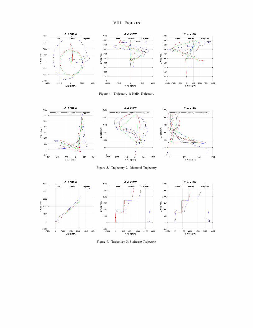
Inspecting the staircase trajectory (trajectory 3) shown infigure 6 one can see that the odometry data valiantly followsthe waypoints, meeting at each vertex. Some minor issues existwhen only considering the odometery, namely there is slightovershoot in the x-y plane. This causes the trajectory as seenby the odometry to bend out slightly from the straight verticalsegments.
The caveat here is that the vicon data does not supportthe odometry readings. Examining the X-Z and Y-Z viewsit is clear that the vehicle tends to drift in the X-Y planewithout accounting for it in odometry readings, This causesthe absolute distance between the ”corners” of the staircaseas measured by odometry and vicon data to increase withtime. An accumulation of error over time of this magnitude isunacceptable for control implementation and is likely an issuewith the downward facing optical flow camera.

The odometry Z-axis readings do not exhibit this same levelof drift, which can be assumed to mean that the down facingsonar data is more dependable than the optic flow camera dataregarding position.
Inspecting the Helix trajectory (trajectory 1) shown infigure 4 a similar conclusion is reached. While the vehicleodometry shows good tracking of waypoints, the odometry isnot accurate. The Z-axis odometry readings once again showadequate correlation with vicon, however the X-Y readingsare completely off. Looking at the X-Y view it is clear thatthe vicon data drifts further away from odometry with time.Again, the vehicle does not record it’s movement in the X-Y plane when it does indeed move. This issue was the maincause of the first crash of this trajectory.
Finally, inspecting the Diamond trajectory the same con-clusions can be reached. However this trajectory illustratesone of the flaws with the algorithm that isn’t tied to faultyodometry readings. It is clear here that the vehicle does notfollow straight line paths between nodes due to conservedvelocity upon reaching a node. If percise movement is neededthis velocity could lead to crashes between waypoints even ifodometry readings are perfect. A simple fix is implementable.Consider the waypoint reached if the vehicle is within someerror of it in space as before, but now add a requirement forthe magnitude of velocity to also be below some error.
VI. LESSONS LEARNED
The clear lesson that vicon data reveals is that odometryreadings do not agree with real positions. In testing the vehicleperformed qualitatively better. So poor odometry could be dueto the environment, or some hardware issue. The root causeof this should be investigated.
In terms of more directly actionable lessons, these resultsshow a velocity requirement would be beneficial for morestraight-line maneuvers between nodes, and there is reasonto tune X-Y gains for overshoot.
VII. CONCLUSION
Despite a poor showing at demonstrations, the data fromthose tests is valuable at exposing issues that are not due tothe trajectory controller, and illustrating room for improvementwith regard to the trajectory controller itself.
REFERENCES
[1] Sebastian OH Madgwick, Andrew JL Harrison, and Ravi Vaidyanathan.”Estimation of IMU and MARG orientation using a gradient descentalgorithm.” 2011 IEEE international conference on rehabilitation robotics.IEEE, 2011.
[2] Edgar Kraft. ”A Quaternion-based Unscented Kalman Filter for Orien-tation Tracking.” Sixth International Conference of Information Fusion.IEEE, 2003.
[3] https://prgaero.github.io/2019/proj/p1a/report[4] https://www.x-io.co.uk/res/doc/madgwick internal report.pdf[5] http://www.stengel.mycpanel.princeton.edu/Quaternions.pdf
VIII. FIGURES
Figure 4. Trajectory 1: Helix Trajectory
Figure 5. Trajectory 2: Diamond Trajectory
Figure 6. Trajectory 3: Staircase Trajectory


![arXiv:1511.04668v2 [cs.CV] 26 Nov 2015 · Our primary quadcopter is the Parrot Bebop Drone (Figure 1). This quadcopter is currently available to the general public. The Bebop drone](https://img.pdfslide.us/doc/110x75/5b8391247f8b9a940b8d56dd/arxiv151104668v2-cscv-26-nov-2015-our-primary-quadcopter-is-the-parrot.jpg)