Embed Size (px)
Citation preview
Training_Transmission_GB Page 1
Transmission
September 2013
Training_Transmission_GB Page 2
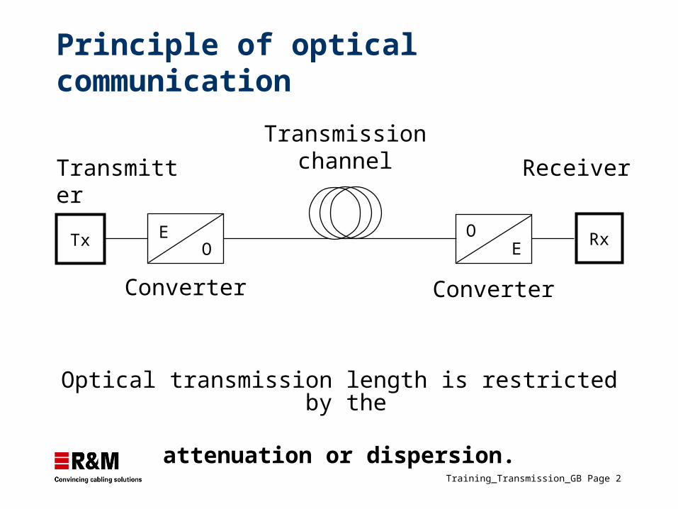
Principle of optical communication
Transmissionchannel
Tx EO
RxOE
Receiver
Converter
Transmitter
Converter
Optical transmission length is restricted by the
attenuation or dispersion.
Training_Transmission_GB Page 3
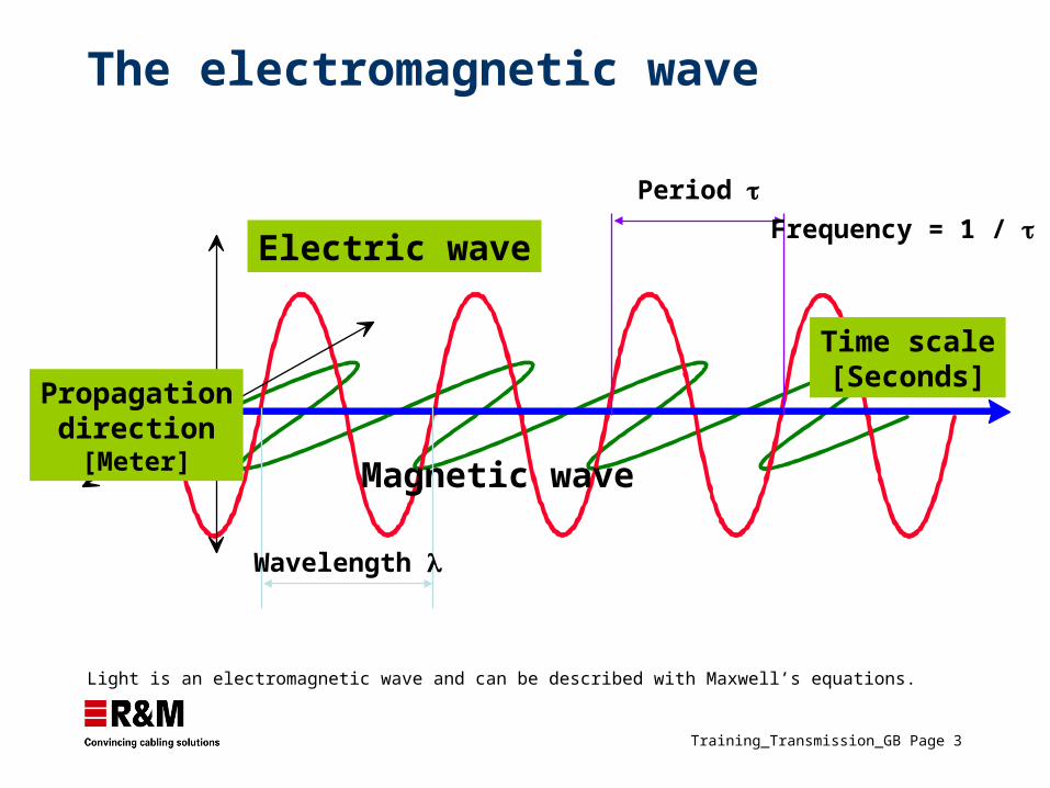
The electromagnetic wave
Electric wave
Magnetic wave
Propagationdirection
[Meter]
Wavelength
Time scale[Seconds]
Period Frequency = 1 /
Light is an electromagnetic wave and can be described with Maxwell’s equations.
Training_Transmission_GB Page 4
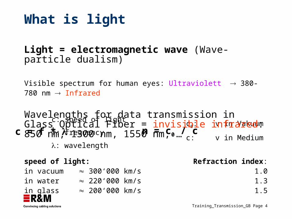
c = f * c: speed of light
f: frequency
: wavelength
n = c0 / cc0: v in Vakuum
c: v in Medium
What is light
speed of light: Refraction index:in vacuum 300‘000 km/s 1.0in water 220‘000 km/s 1.3in glass 200‘000 km/s 1.5
Light = electromagnetic wave (Wave-particle dualism)
Visible spectrum for human eyes: Ultraviolett 380-780 nm Infrared
Wavelengths for data transmission in Glass Optical Fiber = invisible infrared: 850 nm, 1300 nm, 1550 nm, …
Training_Transmission_GB Page 5
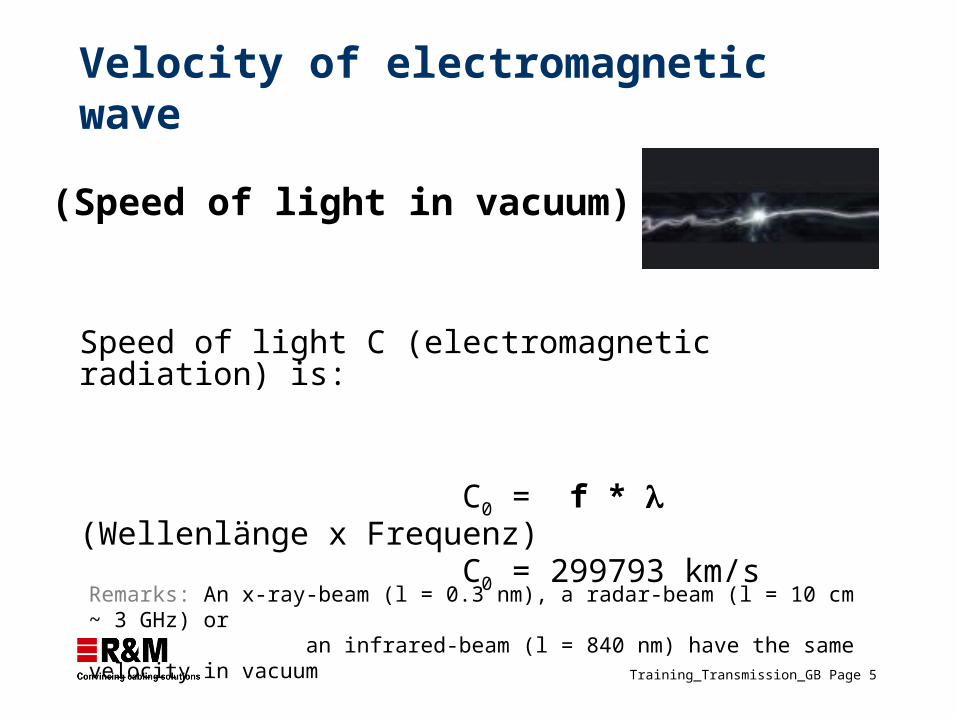
(Speed of light in vacuum)
Speed of light C (electromagnetic radiation) is:
C0 = f * (Wellenlänge x Frequenz) C0 = 299793 km/s
Velocity of electromagnetic wave
Remarks: An x-ray-beam (l = 0.3 nm), a radar-beam (l = 10 cm ~ 3 GHz) or an infrared-beam (l = 840 nm) have the same velocity in vacuum
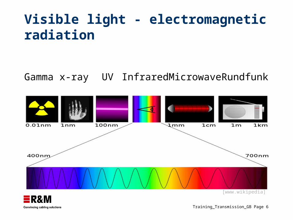
Training_Transmission_GB Page 6
Gamma x-ray UV Infrared Microwave Rundfunk
Visible light - electromagnetic radiation
[www.wikipedia]
Training_Transmission_GB Page 7
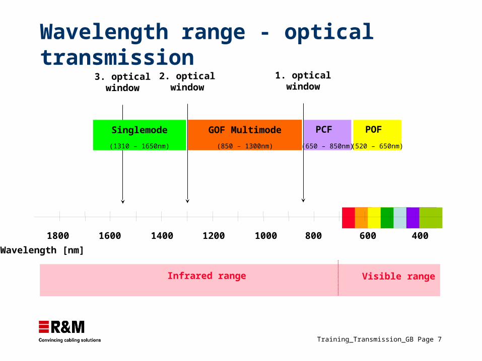
Wavelength range - optical transmission
Infrared range Visible range
GOF Multimode
(850 – 1300nm)
POF (520 – 650nm)
PCF (650 – 850nm)
1. opticalwindow
1800 1600 1400 1200 1000 800 600 400
Wavelength [nm]
2. opticalwindow
3. opticalwindow
Singlemode
(1310 – 1650nm)
Training_Transmission_GB Page 8
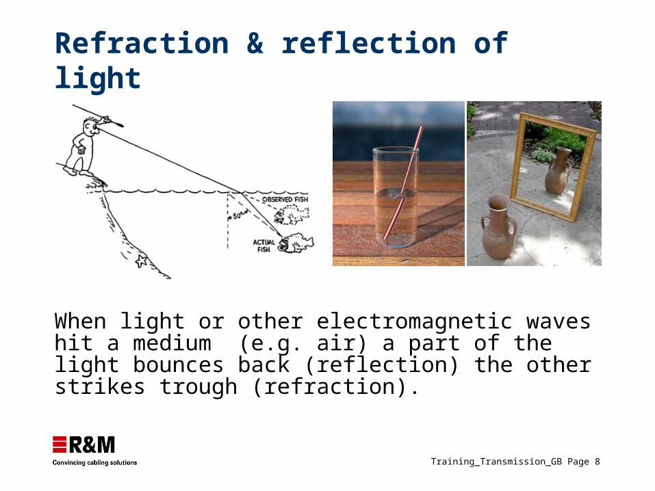
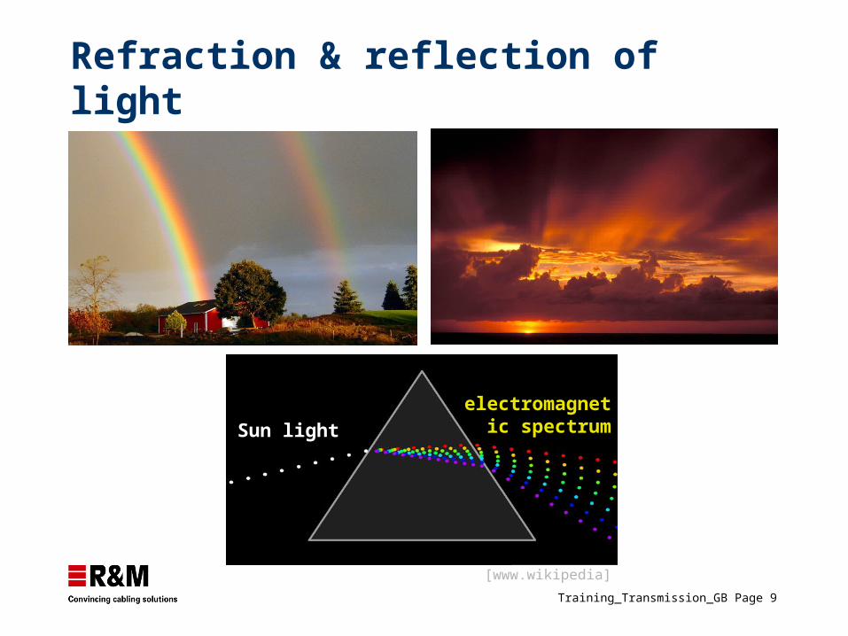
When light or other electromagnetic waves hit a medium (e.g. air) a part of the light bounces back (reflection) the other strikes trough (refraction).
Refraction & reflection of light
Training_Transmission_GB Page 9
Sun light
[www.wikipedia]
Refraction & reflection of light
electromagnetic spectrum
Training_Transmission_GB Page 10
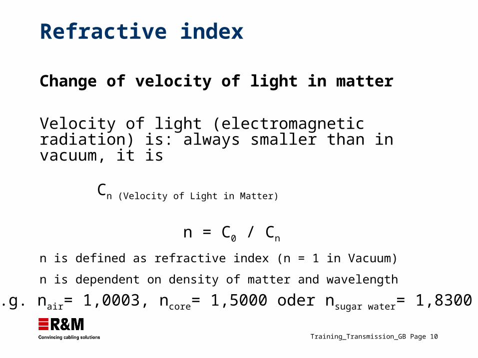
e.g. nair= 1,0003, ncore= 1,5000 oder nsugar water= 1,8300
Change of velocity of light in matter
Velocity of light (electromagnetic radiation) is: always smaller than in vacuum, it is
Cn (Velocity of Light in Matter)
n = C0 / Cn
n is defined as refractive index (n = 1 in Vacuum)
n is dependent on density of matter and wavelength
Refractive index

Training_Transmission_GB Page 11
Transmission
Training_Transmission_GB Page 12
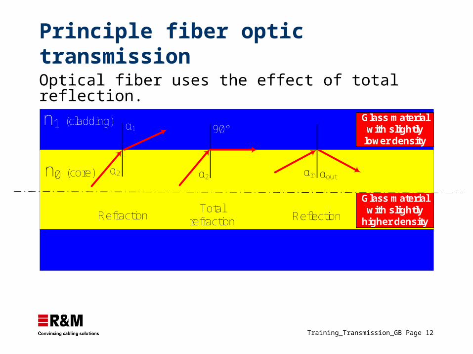
Principle fiber optic transmission
Optical fiber uses the effect of total reflection.
RefractionTotal
refraction Reflection
Glass material with slightly
lower density
n1 (cladding)
n0 (core) α2
α1
α2
90°
αin αout
Glass material with slightly
higher density
Training_Transmission_GB Page 13
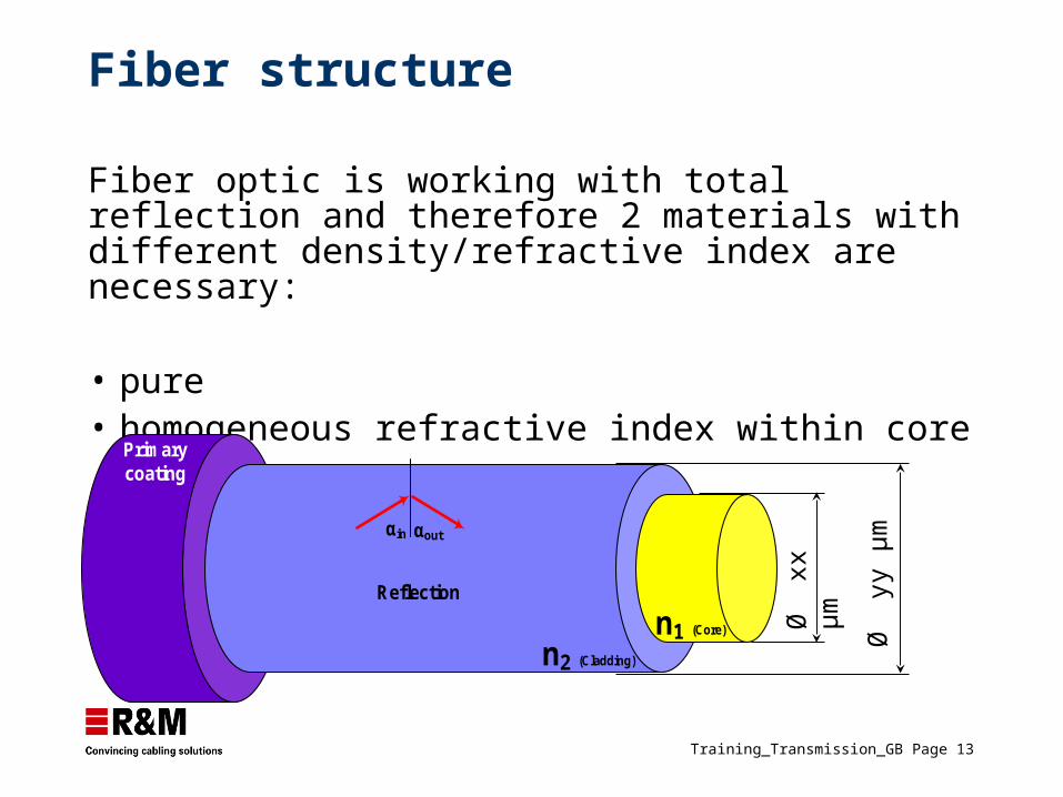
Fiber structure
Fiber optic is working with total reflection and therefore 2 materials with different density/refractive index are necessary:
• pure• homogeneous refractive index within core
Ø
yy µ
m
Ø
xx µ
m
n2 (Cladding)
n1 (Core)
Reflection
αin αout
Primary coating
Training_Transmission_GB Page 14
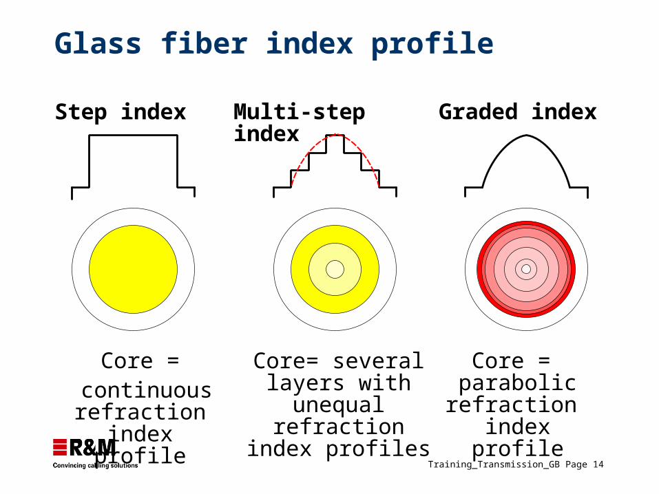
Glass fiber index profile
Core = continuous
refraction index profile
Core= several layers with unequal
refraction index profiles
Core = parabolic
refraction index profile
Step index Multi-step index Graded index
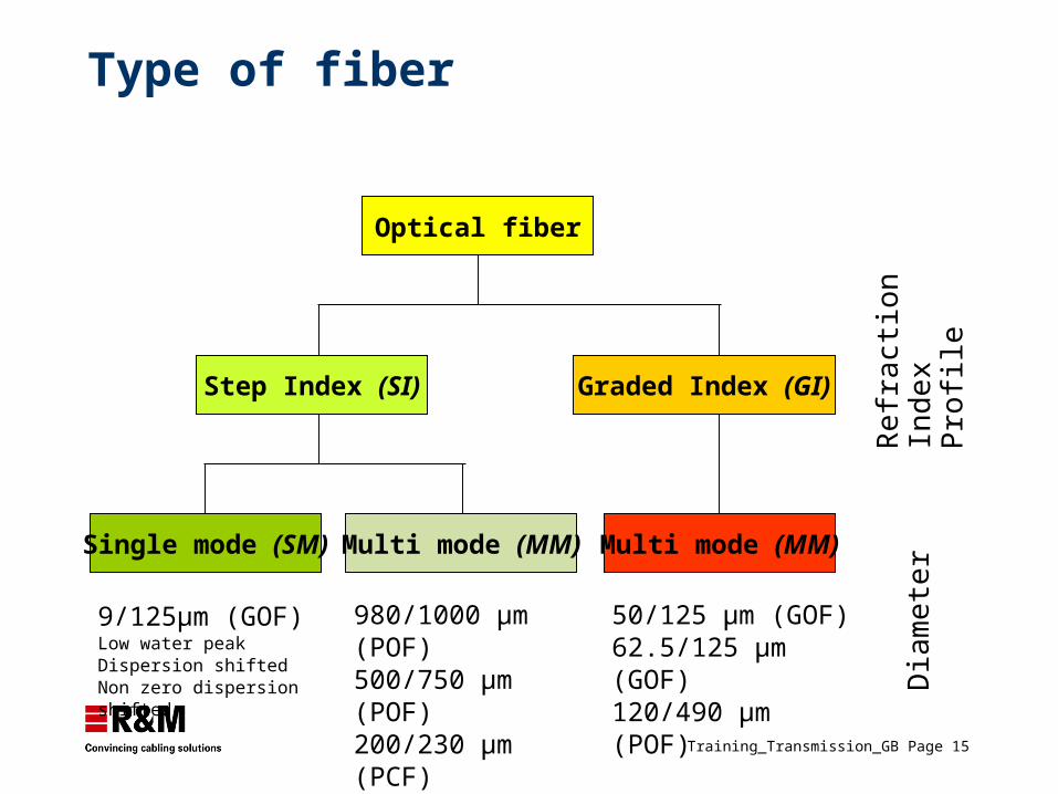
Training_Transmission_GB Page 15
Type of fiber
Optical fiber
Step Index (SI) Graded Index (GI)
Single mode (SM) Multi mode (MM) Multi mode (MM)
9/125µm (GOF)Low water peakDispersion shiftedNon zero dispersion shifted
980/1000 µm (POF)500/750 µm (POF)200/230 µm (PCF)
50/125 µm (GOF)62.5/125 µm (GOF) 120/490 µm (POF) D
iam
ete
rR
efr
actio
nIn
de
xP
rofil
e
Training_Transmission_GB Page 16
n1 n2
Refractive indexprofile
(Step index)
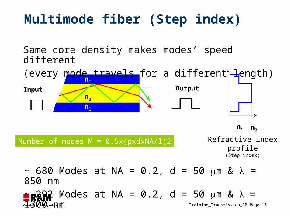
~ 680 Modes at NA = 0.2, d = 50 m & = 850 nm~ 292 Modes at NA = 0.2, d = 50 m & = 1300 nm
Number of modes M = 0.5x(pxdxNA/l)2
n1
n2
n1
Same core density makes modes’ speed different (every mode travels for a different length)
Multimode fiber (Step index)
Input Output
Training_Transmission_GB Page 17
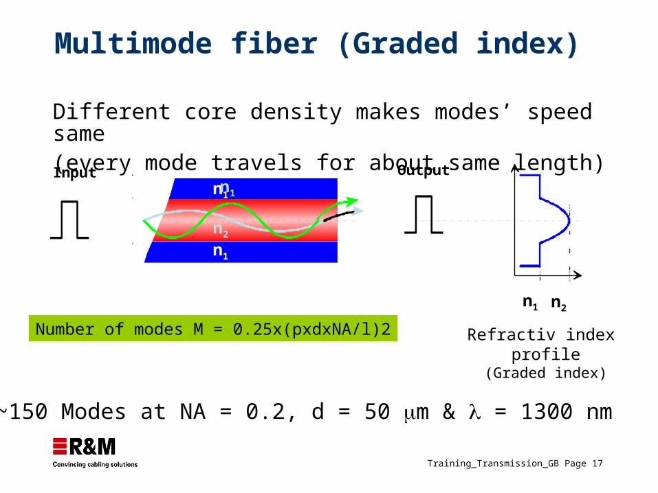
Multimode fiber (Graded index)
Refractiv index profile
(Graded index)
~150 Modes at NA = 0.2, d = 50 m & = 1300 nm
Number of modes M = 0.25x(pxdxNA/l)2
n1
n1n1
Input Output
n1 n2
n2
Different core density makes modes’ speed same(every mode travels for about same length)
Training_Transmission_GB Page 18
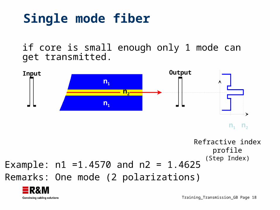
Single mode fiber
Refractive indexprofile
(Step Index)Example: n1 =1.4570 and n2 = 1.4625Remarks: One mode (2 polarizations)
n1 n2
n1
n1
n2
Input Output
if core is small enough only 1 mode can get transmitted.
Training_Transmission_GB Page 20
Optical characteristics
Training_Transmission_GB Page 21
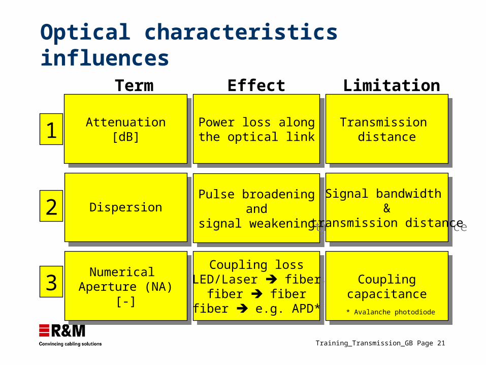
Optical characteristics influences
1
2
3
Attenuation[dB]
Attenuation[dB]
DispersionDispersion
Numerical Aperture (NA)
[-]
Numerical Aperture (NA)
[-]
Power loss alongthe optical link
Power loss alongthe optical link
Pulse broadeningand
signal weakening
Pulse broadeningand
signal weakening
Coupling lossLED/Laser fiber
fiber fiberfiber e.g. APD*
Coupling lossLED/Laser fiber
fiber fiberfiber e.g. APD*
Transmission distance
Transmission distance
Signal bandwidth &
transmission distance
Signal bandwidth &
transmission distance
Couplingcapacitance
Couplingcapacitance
Term Effect Limitation
* Avalanche photodiode
Training_Transmission_GB Page 22
Attenuation
Training_Transmission_GB Page 23
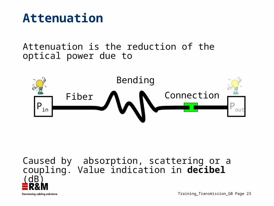
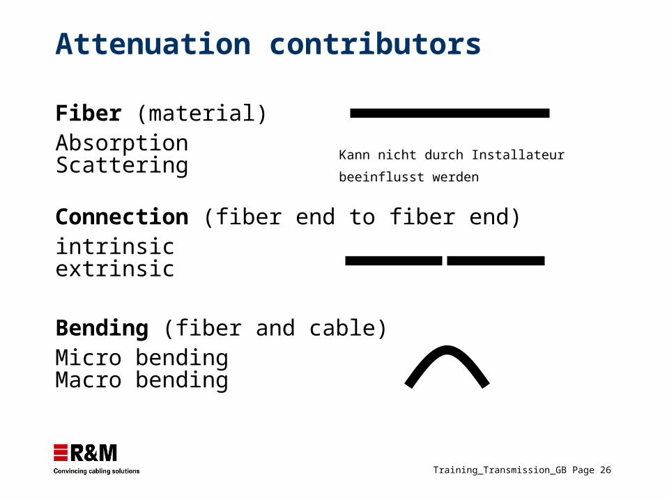
Attenuation is the reduction of the optical power due to
Attenuation
Fiber
Bending
Connection
Caused by absorption, scattering or a coupling. Value indication in decibel (dB)
Pin Pout
Training_Transmission_GB Page 24
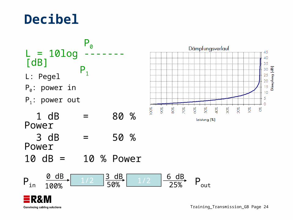
P0
L = 10log ------- [dB] P1
L: Pegel
P0: power in
P1: power out
1 dB = 80 % Power 3 dB = 50 % Power10 dB = 10 % Power
Decibel
1/2 1/23 dB 6 dB0 dB
100% 50% 25%Pin Pout
Training_Transmission_GB Page 25
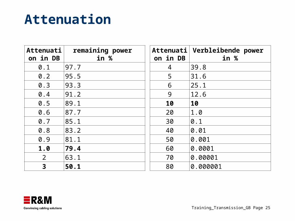
Attenuation
Attenuation in DB
remaining power in %
0.1 97.70.2 95.50.3 93.30.4 91.20.5 89.10.6 87.70.7 85.10.8 83.20.9 81.11.0 79.42 63.13 50.1
Attenuation in DB
Verbleibende power in %
4 39.85 31.66 25.19 12.6
10 1020 1.030 0.140 0.0150 0.00160 0.000170 0.0000180 0.000001
Training_Transmission_GB Page 26
Attenuation contributors
Fiber (material) AbsorptionScattering
Connection (fiber end to fiber end)intrinsic extrinsic
Bending (fiber and cable)Micro bendingMacro bending
Kann nicht durch Installateur beeinflusst werden
Training_Transmission_GB Page 27
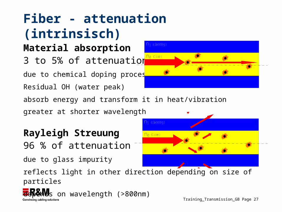
Fiber - attenuation (intrinsisch)
Material absorption3 to 5% of attenuationdue to chemical doping process impurity
Residual OH (water peak)
absorb energy and transform it in heat/vibration
greater at shorter wavelength n1 (cladding)
n0 (Core)Rayleigh Streuung96 % of attenuationdue to glass impurity
reflects light in other direction depending on size of particles
depends on wavelength (>800nm)
n1 (cladding)
n0 (Core)
Training_Transmission_GB Page 28
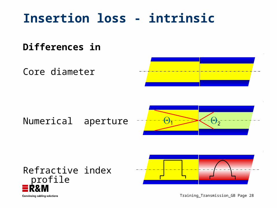
Insertion loss - intrinsic
Differences in
Core diameter
Numerical aperture
Refractive index profile
Training_Transmission_GB Page 29
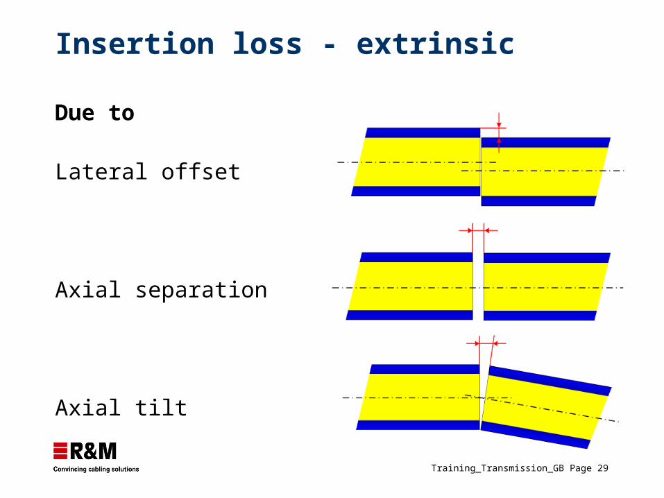
Insertion loss - extrinsic
Due to
Lateral offset
Axial separation
Axial tilt
Training_Transmission_GB Page 30
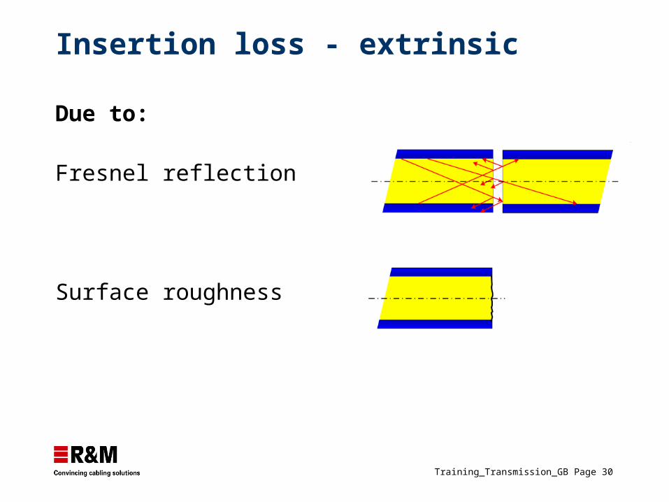
Insertion loss - extrinsic
Due to:
Fresnel reflection
Surface roughness
Training_Transmission_GB Page 31
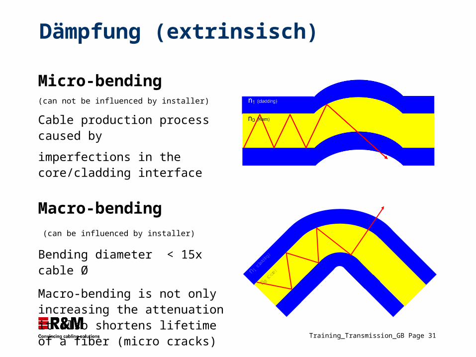
Dämpfung (extrinsisch)
Micro-bending
(can not be influenced by installer)
Cable production process caused by
imperfections in the core/cladding interface
Macro-bending
(can be influenced by installer)
Bending diameter < 15x cable Ø
Macro-bending is not only increasing the attenuation it also shortens lifetime of a fiber (micro cracks)
n 1 (cla
dding
)
n 0 (Cor
e)
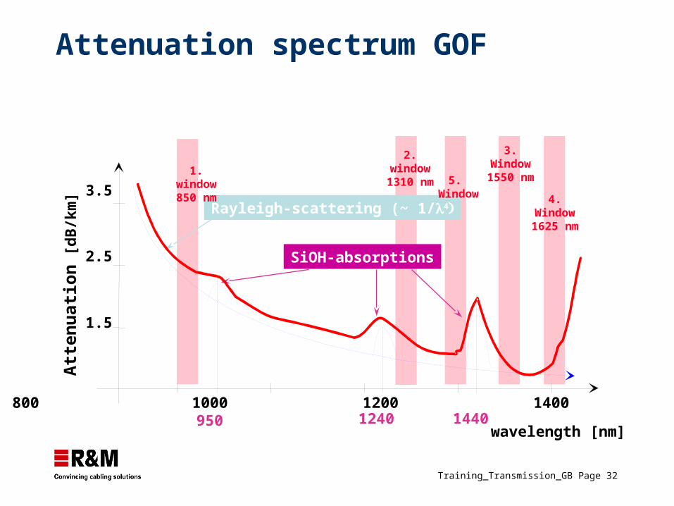
Training_Transmission_GB Page 32
800 1000 1200 1400 1600
wavelength [nm]
3.5
2.5
1.5
Att
enu
atio
n [
dB
/km
]
3.Window1550 nm
SiOH-absorptions
Rayleigh-scattering (~ 1/
950 1240 1440
5. Window 4.
Window1625 nm
Attenuation spectrum GOF
1.window850 nm
2.window1310 nm
Training_Transmission_GB Page 33
Dispersion
Training_Transmission_GB Page 34
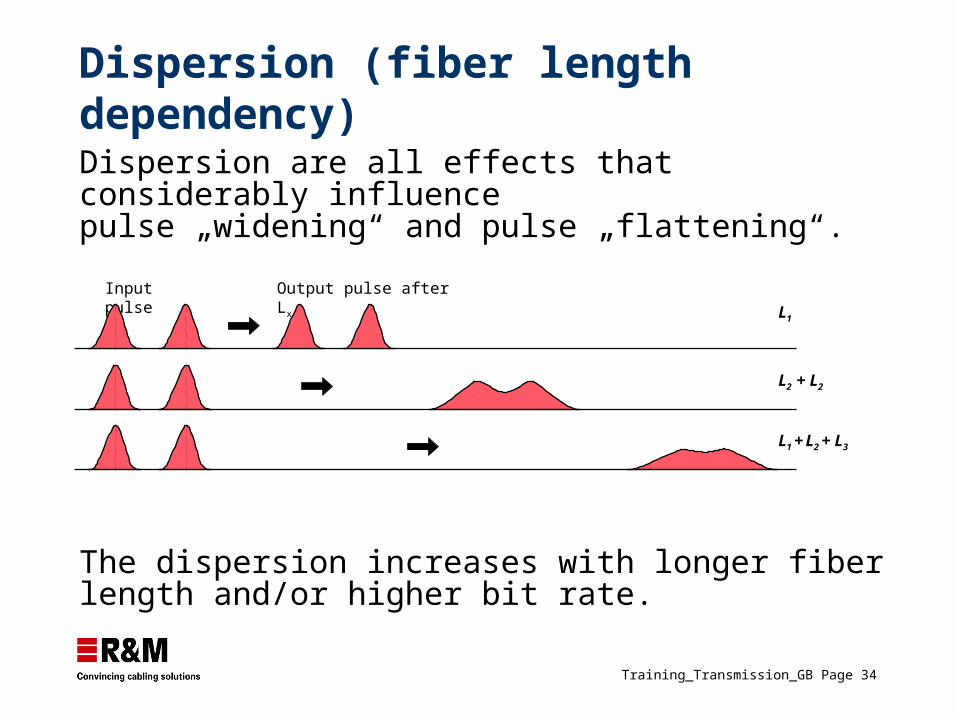
Dispersion (fiber length dependency)
Dispersion are all effects that considerably influence pulse „widening“ and pulse „flattening“.
Input pulse
L1
L2 + L2
L1 + L2 + L3
Output pulse after Lx
The dispersion increases with longer fiber length and/or higher bit rate.
Training_Transmission_GB Page 35
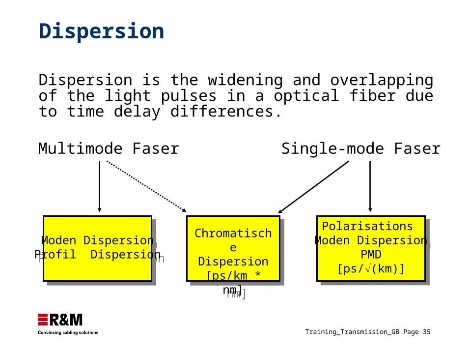
Dispersion
Moden DispersionProfil Dispersion
Moden DispersionProfil Dispersion
ChromatischeDispersion
[ps/km * nm]
ChromatischeDispersion
[ps/km * nm]
Polarisations Moden Dispersion
PMD[ps/(km)]
Polarisations Moden Dispersion
PMD[ps/(km)]
Multimode Faser Single-mode Faser
Dispersion is the widening and overlapping of the light pulses in a optical fiber due to time delay differences.
Training_Transmission_GB Page 37
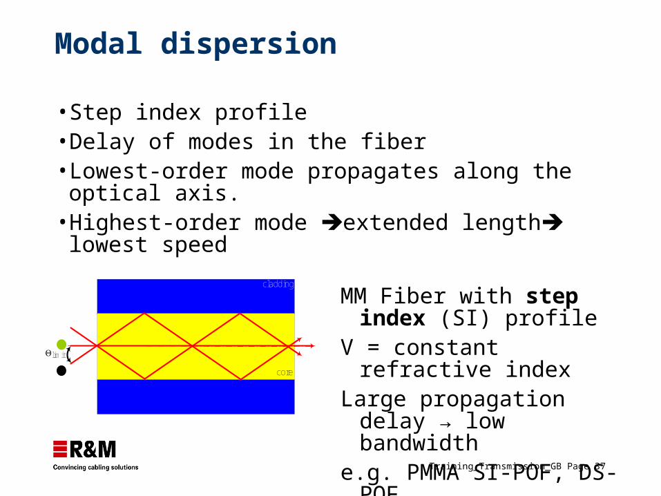
Modal dispersion
• Step index profile• Delay of modes in the fiber• Lowest-order mode propagates along the optical axis.• Highest-order mode extended length lowest speed
cladding
core
limit
MM Fiber with step index (SI) profile
V = constant refractive indexLarge propagation delay →
low bandwidthe.g. PMMA SI-POF, DS-POF
Training_Transmission_GB Page 38
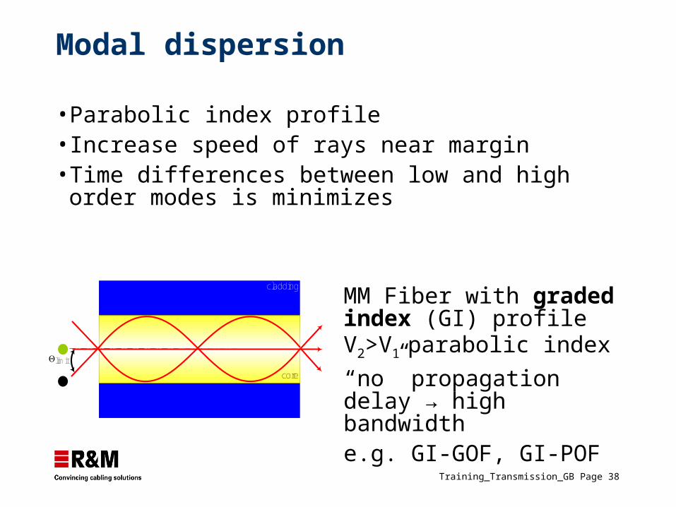
Modal dispersion
• Parabolic index profile• Increase speed of rays near margin• Time differences between low and high order modes is
minimizes
cladding
core
limit
MM Fiber with graded index (GI) profileV2>V1 parabolic index
“no” propagation delay → high bandwidthe.g. GI-GOF, GI-POF
Training_Transmission_GB Page 39
Chromatic dispersion
Singlemode chromatic dispersion Dominant type of dispersion in SM fibers and is caused by wavelength dependent effects. Chromatic dispersion is the cumulative effect of material and waveguide dispersion
Multimode chromatic dispersionAs waveguide dispersion is very low compared to material dispersion it can be disregarded.
Training_Transmission_GB Page 42
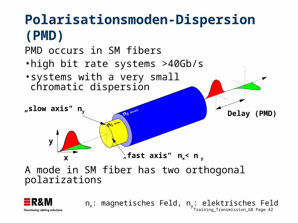
Delay (PMD)n2 (Mantel)
n1 (Kern)
Polarisationsmoden-Dispersion (PMD)
„slow axis" ny
„fast axis“ nx< n y
y
x
PMD occurs in SM fibers• high bit rate systems >40Gb/s• systems with a very small chromatic
dispersion
A mode in SM fiber has two orthogonal polarizations
nx: magnetisches Feld, ny: elektrisches Feld
Training_Transmission_GB Page 43
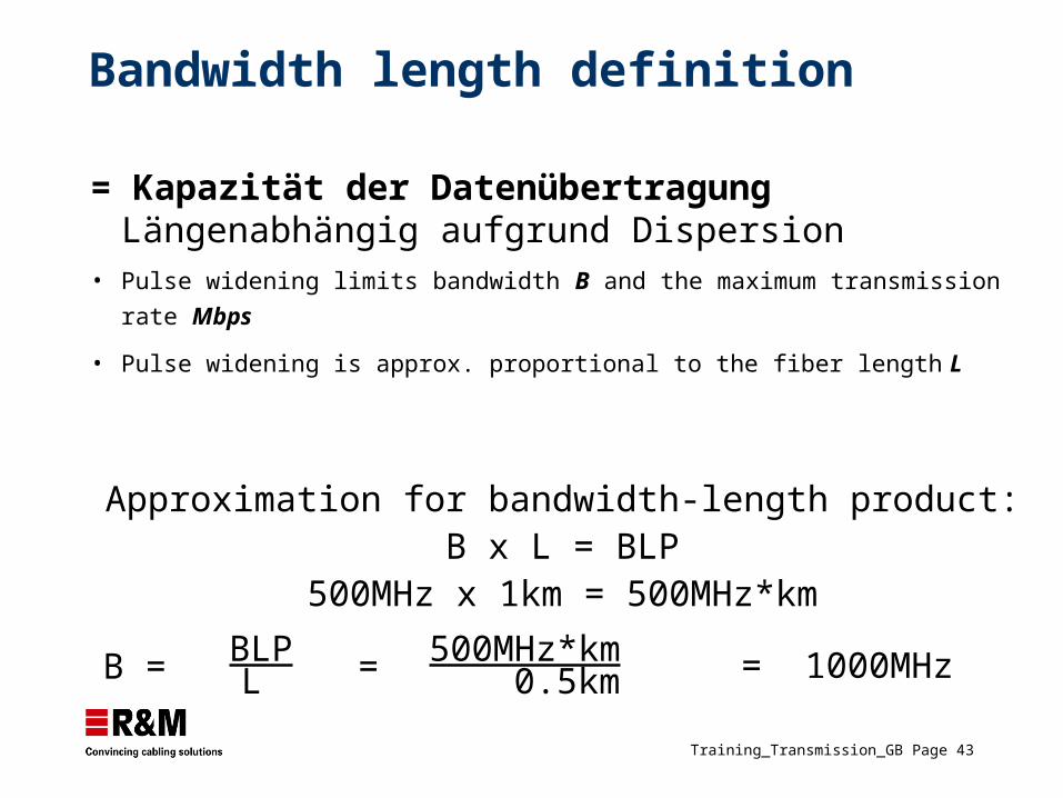
Bandwidth length definition
= Kapazität der Datenübertragung Längenabhängig aufgrund Dispersion
• Pulse widening limits bandwidth B and the maximum transmission rate Mbps
• Pulse widening is approx. proportional to the fiber length L
Approximation for bandwidth-length product:B x L = BLP
500MHz x 1km = 500MHz*km
BLPL
500MHz*km0.5kmB = = = 1000MHz
Training_Transmission_GB Page 44
Numerical aperture
Training_Transmission_GB Page 45
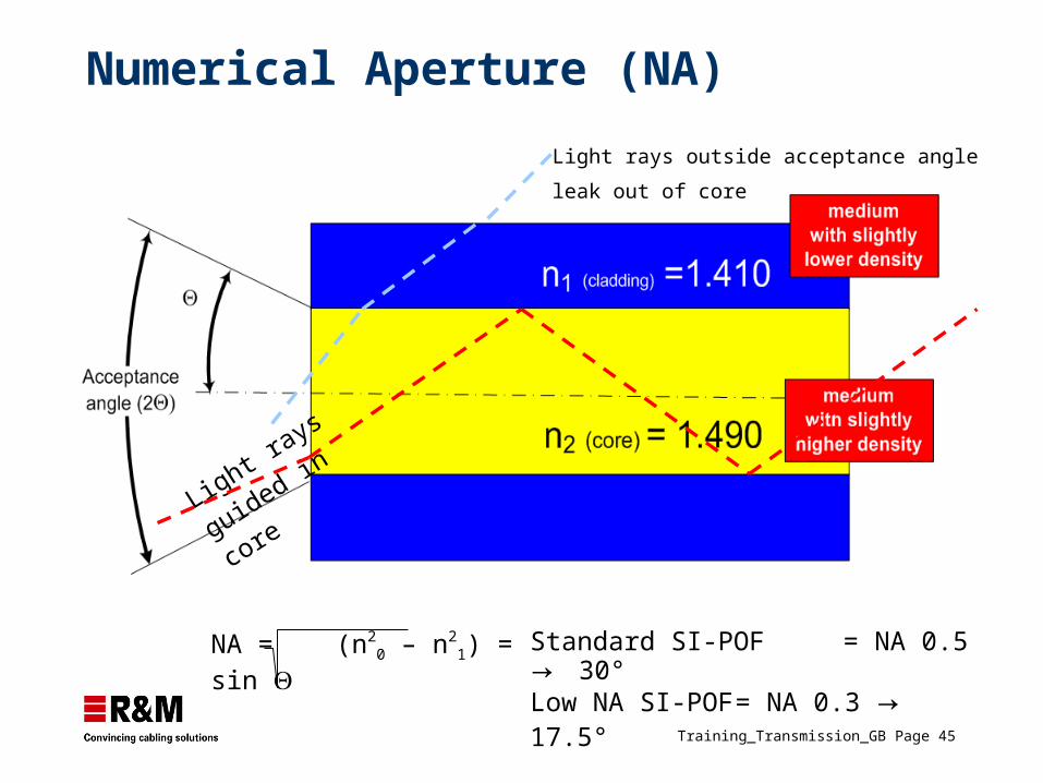
Numerical Aperture (NA)
Light rays outside acceptance angle leak out of
core
NA = (n20 – n2
1) = sin Standard SI-POF = NA 0.5 → 30°Low NA SI-POF = NA 0.3 → 17.5°
Light rays guided
in core
Training_Transmission_GB Page 46
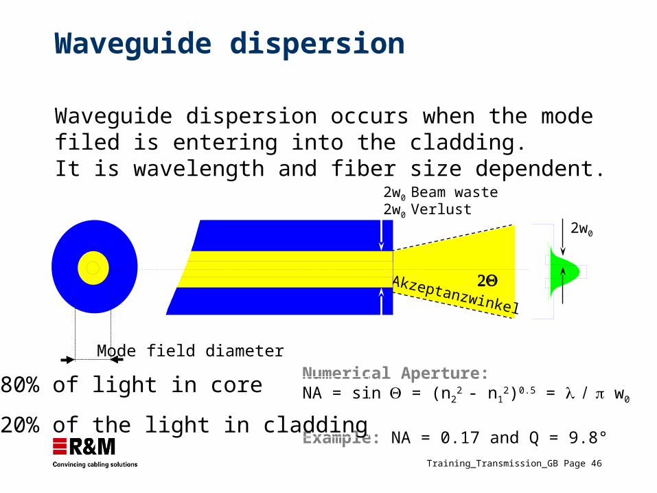
Waveguide dispersion
2w0 Beam waste
Numerical Aperture: NA = sin = (n2
2 - n12)0.5 = w0
Example: NA = 0.17 and Q = 9.8°
80% of light in core
20% of the light in cladding
2w0 Verlust
Akzeptanzwinkel
Mode field diameter
2w0
Waveguide dispersion occurs when the mode filed is entering into the cladding. It is wavelength and fiber size dependent.