Embed Size (px)
Citation preview
TRAINING WORKSHOP ON NON-WOVENS IN GEOTEXTILES
AT SURAT
BY
S.K. PURI
CHIEF GENERAL MANAGER - NHAI
5TH MARCH 2008
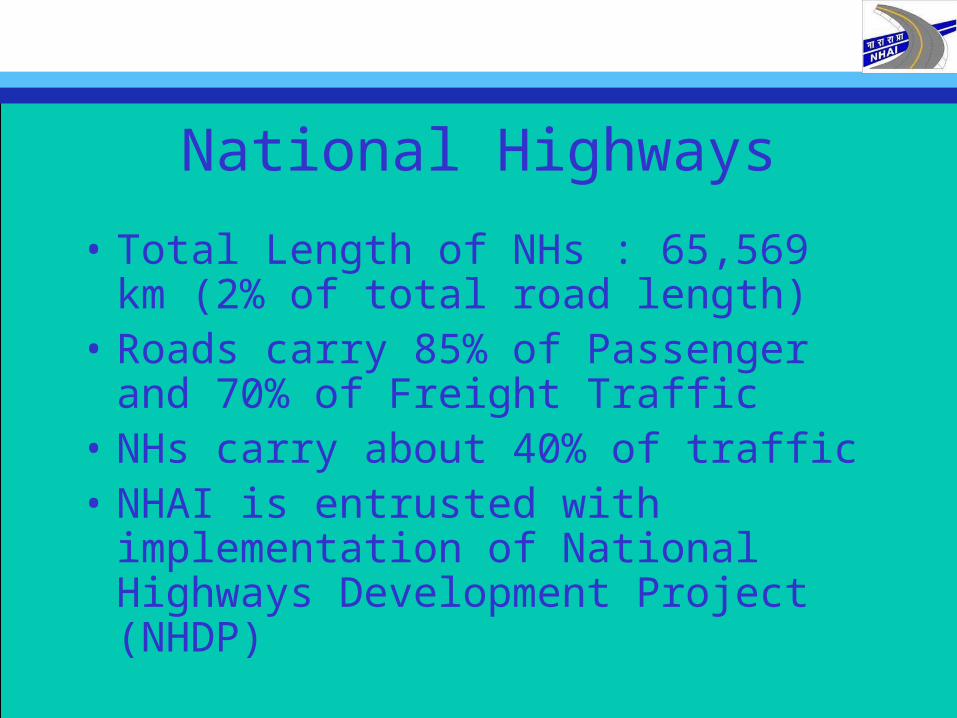
National Highways
• Total Length of NHs : 65,569 km (2% of total road length)
• Roads carry 85% of Passenger and 70% of Freight Traffic
• NHs carry about 40% of traffic • NHAI is entrusted with implementation of
National Highways Development Project (NHDP)
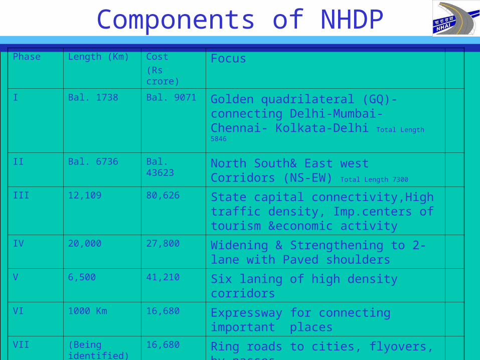
Components of NHDPPhase Length (Km) Cost
(Rs crore)Focus
I Bal. 1738 Bal. 9071 Golden quadrilateral (GQ)- connecting Delhi-Mumbai-Chennai- Kolkata-Delhi Total Length 5846
II Bal. 6736 Bal. 43623 North South& East west Corridors (NS-EW) Total Length 7300
III 12,109 80,626 State capital connectivity,High traffic density, Imp.centers of tourism &economic activity
IV 20,000 27,800 Widening & Strengthening to 2-lane with Paved shoulders
V 6,500 41,210 Six laning of high density corridors
VI 1000 Km 16,680 Expressway for connecting important places
VII (Being identified) 16,680 Ring roads to cities, flyovers, by-passes
SARDP-NE 588 5208 Special Accelerated Road Development Programme for NE
ICTT Cochin
17 557 International Container Transhipment Terminal
Total 48,688 2,41,454

Definition, Type, Process and PropertiesDefinition, Type, Process and Properties
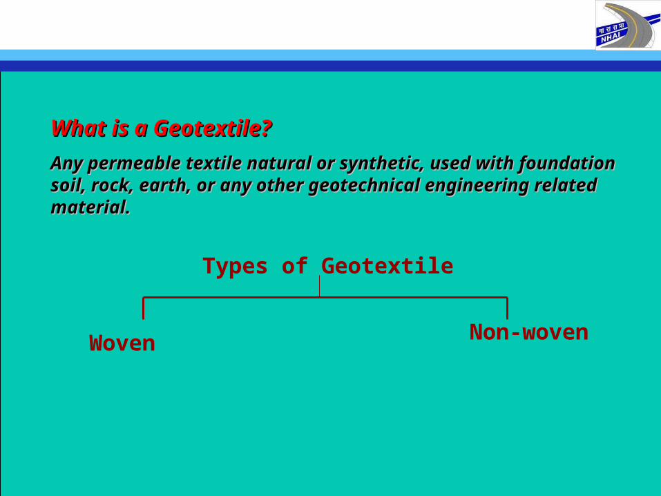
Any permeable textile natural or synthetic, used with foundation Any permeable textile natural or synthetic, used with foundation soil, rock, earth, or any other geotechnical engineering related soil, rock, earth, or any other geotechnical engineering related material.material.
What is a Geotextile?What is a Geotextile?
Types of Geotextile
Woven Non-woven
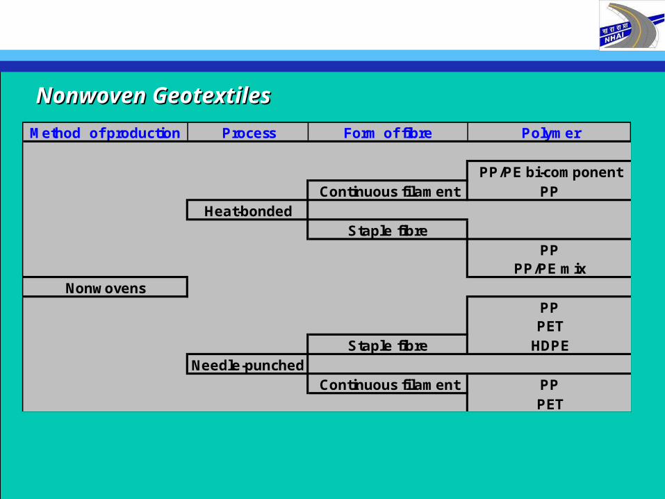
Method of production Process Form of fibre Polymer
PP/PE bi-componentContinuous filament PP
Heat-bondedStaple fibre
PPPP/PE mix
NonwovensPPPET
Staple fibre HDPENeedle-punched
Continuous filament PPPET
Nonwoven GeotextilesNonwoven Geotextiles
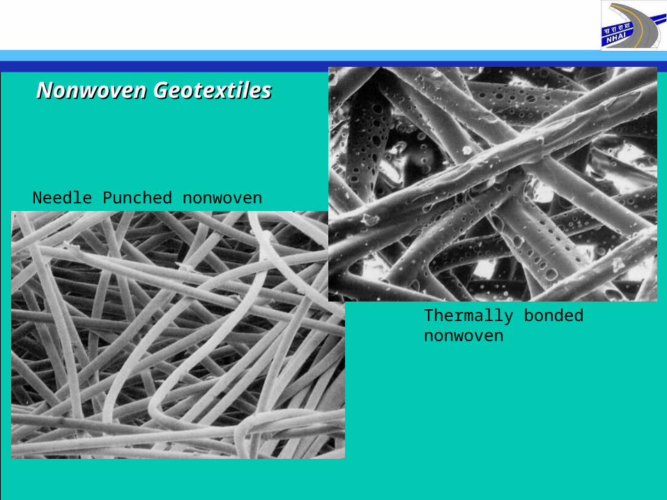
Needle Punched nonwoven
Thermally bonded nonwoven
Nonwoven GeotextilesNonwoven Geotextiles
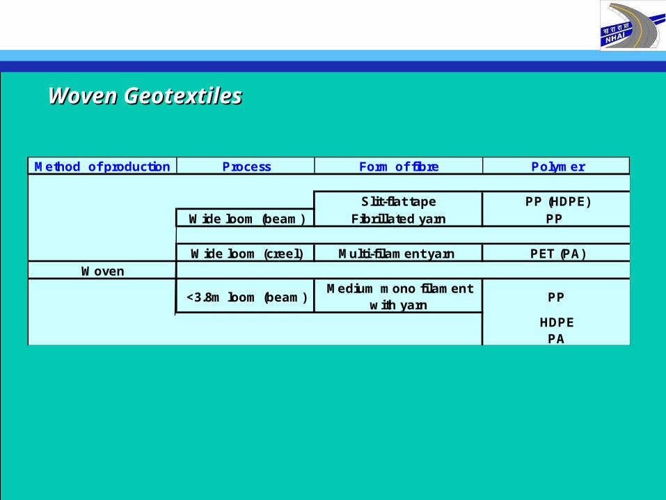
Method of production Process Form of fibre Polymer
Slit-flat tape PP (HDPE)Wide loom (beam) Fibrillated yarn PP
Wide loom (creel) Multi-filament yarn PET (PA)Woven
<3.8m loom (beam)Medium mono filament
with yarnPP
HDPEPA
Woven GeotextilesWoven Geotextiles
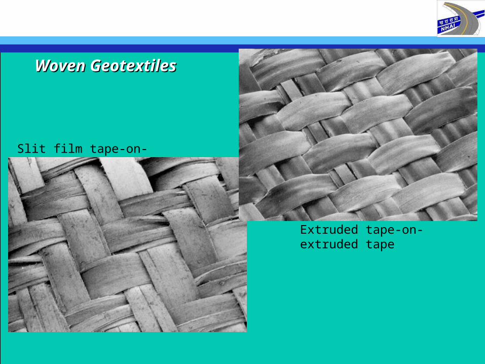
Slit film tape-on-slit film tape
Extruded tape-on-extruded tape
Woven GeotextilesWoven Geotextiles
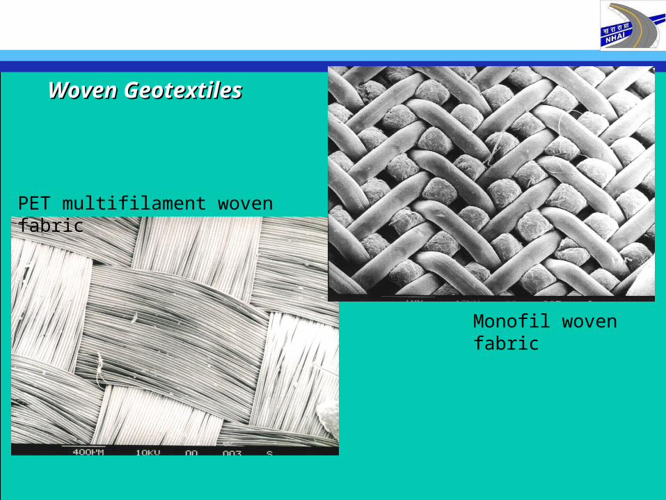
Monofil woven fabric
PET multifilament woven fabric
Woven GeotextilesWoven Geotextiles
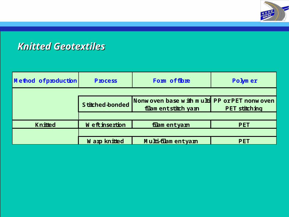
Method of production Process Form of fibre Polymer
Stitched-bondedNonwoven base with multi-
filament stitch yarnPP or PET nonwoven
PET stitching
Knitted Weft insertion filament yarn PET
Warp knitted Multi-filament yarn PET
Knitted GeotextilesKnitted Geotextiles
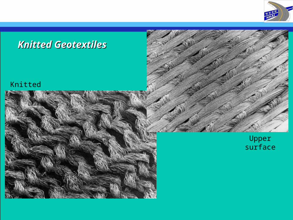
Knitted base
Upper surface
Knitted GeotextilesKnitted Geotextiles
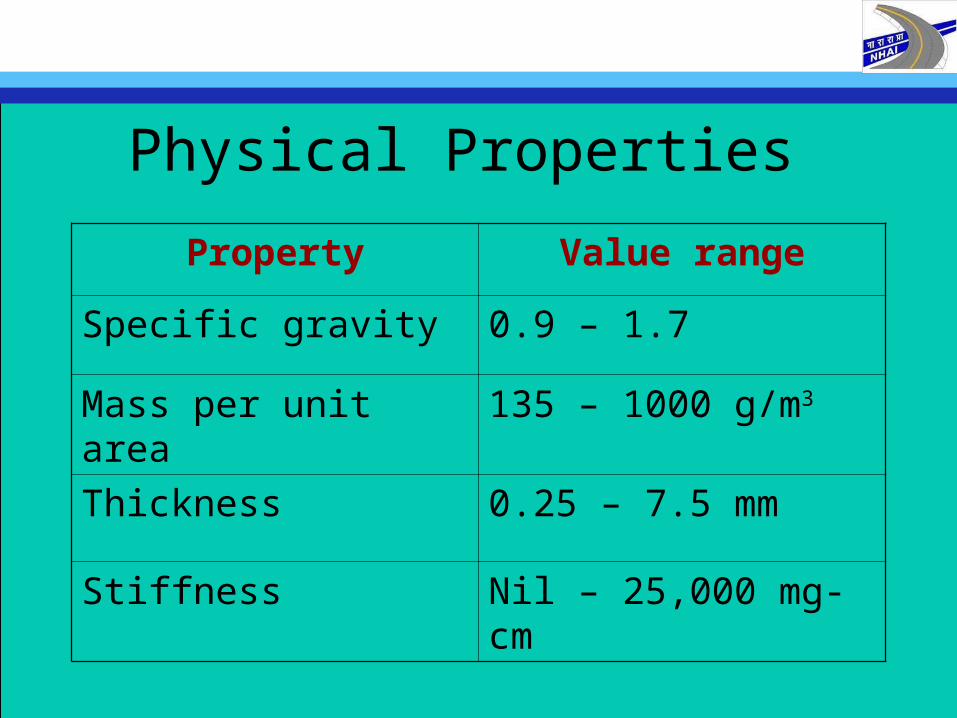
Physical Properties
Property Value range
Specific gravity 0.9 – 1.7
Mass per unit area 135 – 1000 g/m3
Thickness 0.25 – 7.5 mm
Stiffness Nil – 25,000 mg-cm
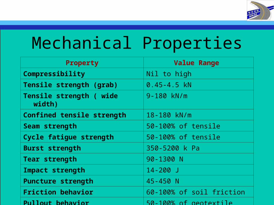
Mechanical PropertiesProperty Value Range
Compressibility Nil to high
Tensile strength (grab) 0.45-4.5 kN
Tensile strength ( wide width) 9-180 kN/m
Confined tensile strength 18-180 kN/m
Seam strength 50-100% of tensile
Cycle fatigue strength 50-100% of tensile
Burst strength 350-5200 k Pa
Tear strength 90-1300 N
Impact strength 14-200 J
Puncture strength 45-450 N
Friction behavior 60-100% of soil friction
Pullout behavior 50-100% of geotextile strength
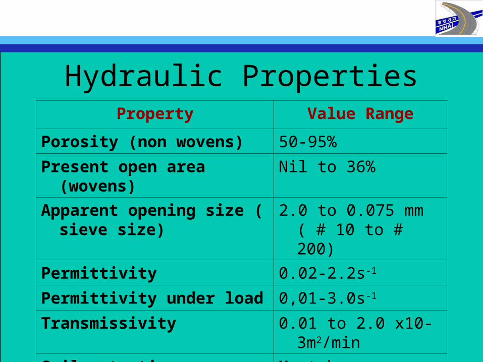
Hydraulic PropertiesProperty Value Range
Porosity (non wovens) 50-95%
Present open area (wovens) Nil to 36%
Apparent opening size ( sieve size)
2.0 to 0.075 mm ( # 10 to # 200)
Permittivity 0.02-2.2s-1
Permittivity under load 0,01-3.0s-1
Transmissivity 0.01 to 2.0 x10⁻³m2/min
Soil retention: turbidity curtains Must be evaluated
Soil retention: silt fences Must be evaluated
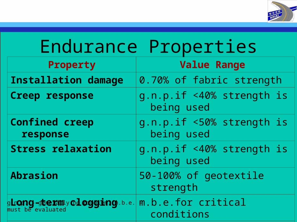
Endurance PropertiesProperty Value Range
Installation damage 0.70% of fabric strength
Creep response g.n.p.if <40% strength is being used
Confined creep response g.n.p.if <50% strength is being used
Stress relaxation g.n.p.if <40% strength is being used
Abrasion 50-100% of geotextile strength
Long-term clogging m.b.e.for critical conditions
Gradient ratio clogging m.b.e. for critical conditions
Hydraulic conductivity ratio 0.4-0.8 appear to be acceptable
g.n.p. – generally no problem, m.b.e. – must be evaluated
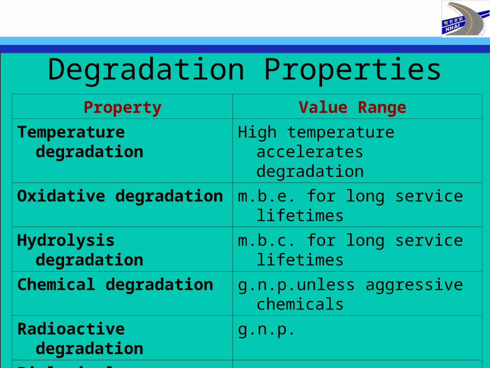
Degradation PropertiesProperty Value Range
Temperature degradation High temperature accelerates degradation
Oxidative degradation m.b.e. for long service lifetimes
Hydrolysis degradation m.b.c. for long service lifetimes
Chemical degradation g.n.p.unless aggressive chemicals
Radioactive degradation g.n.p.
Biological degradation g.n.p.
Sunlight ( UV) degradation Major problem unless protected
Synergistic effects m.b.e.
General aging Actual record to date is excellent
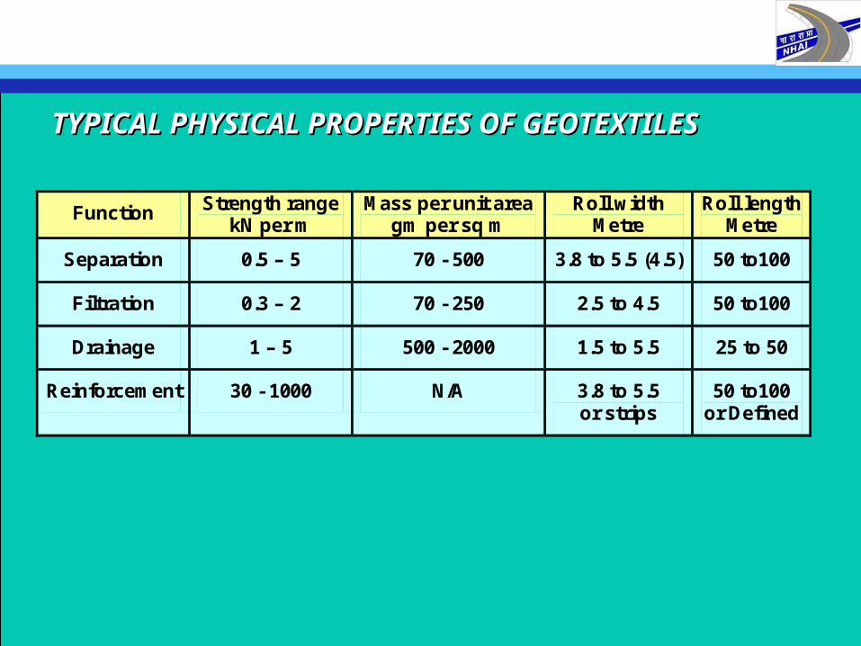
TYPICAL PHYSICAL PROPERTIES OF GEOTEXTILESTYPICAL PHYSICAL PROPERTIES OF GEOTEXTILES
Function Strength range kN per m
Mass per unit area gm per sq m
Roll width Metre
Roll length Metre
Separation 0.5 – 5 70 - 500 3.8 to 5.5 (4.5) 50 to100
Filtration 0.3 – 2 70 - 250 2.5 to 4.5 50 to100
Drainage 1 – 5 500 - 2000 1.5 to 5.5 25 to 50
Reinforcement 30 - 1000 N/A 3.8 to 5.5 or strips
50 to100 or Defined
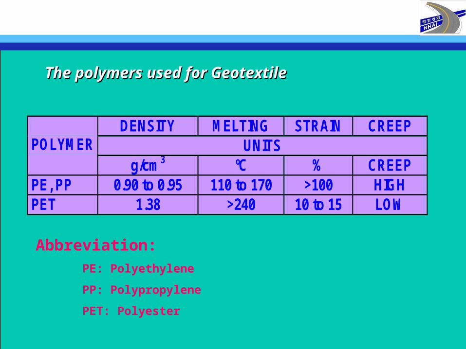
DENSITY MELTING STRAIN CREEP UNITS
POLYMER
g/cm3 ºC % CREEP PE, PP 0.90 to 0.95 110 to 170 >100 HIGH PET 1.38 >240 10 to 15 LOW
The polymers used for GeotextileThe polymers used for Geotextile
Abbreviation:
PE: Polyethylene
PP: Polypropylene
PET: Polyester

EN 12447
Geotextiles and geotextile-related products - Screening test method for determining the resistance to hhyyddrroollyyssiiss in water
EN 12226
Geotextiles and geotextile-related products - General tests for eevvaalluuaattiioonn following durability testing
EN 14030
(ISO 12960)
Geotextiles and geotextile-related products -Screening test method for determining the resistance to aacciidd aanndd aallkkaalliinnee liquids
EN ISO 13438
Geotextiles and geotextile-related products - Screening test method for determining the resistance to ooxxiiddaattiioonn at elevated oxygen pressure
EN ISO 12225
Geotextiles and geotextile-related products - MMiiccrroobbiioollooggiiccaall resistance (soil burial)
Durability Test MethodsDurability Test Methods for Geotextile for Geotextile
Functions and properties of GeotextilesFunctions and properties of Geotextiles
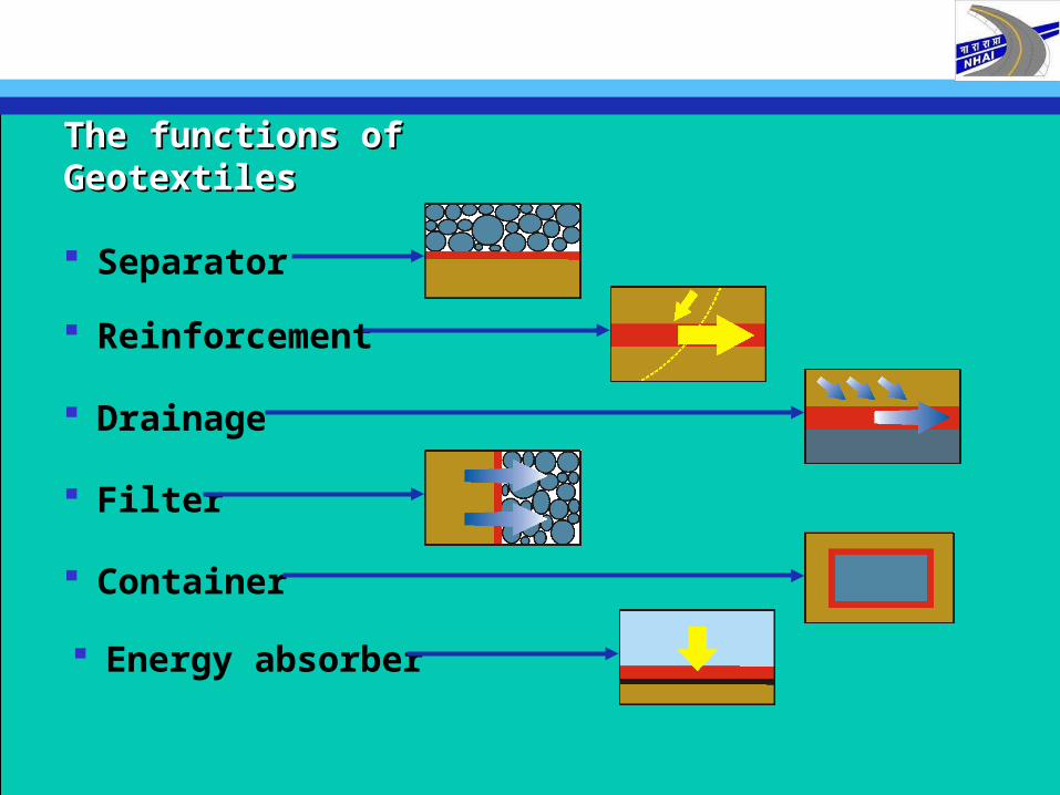
The functions of GeotextilesThe functions of Geotextiles
Separator
Reinforcement
Drainage
Filter
Energy absorber
Container
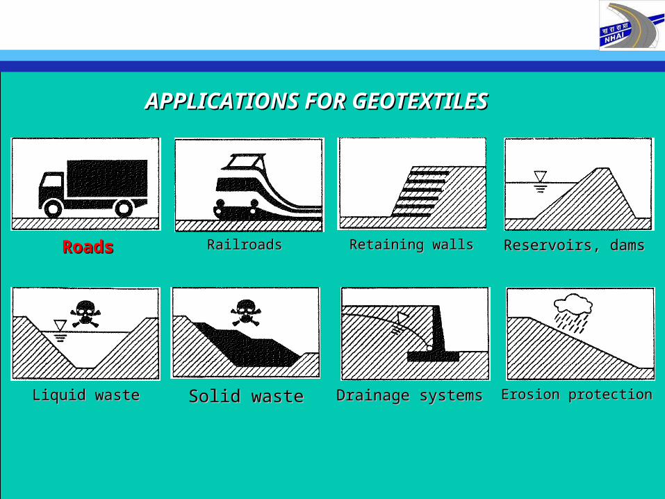
Reservoirs, damsReservoirs, dams
Liquid wasteLiquid waste Solid wasteSolid waste
RoadsRoads RailroadsRailroads
Erosion protectionErosion protection
Retaining wallsRetaining walls
Drainage systemsDrainage systems
APPLICATIONS FOR GEOTEXTILESAPPLICATIONS FOR GEOTEXTILES
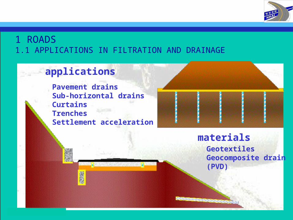
1 ROADS 1.1 APPLICATIONS IN FILTRATION AND DRAINAGE
Pavement drainsSub-horizontal drainsCurtainsTrenchesSettlement acceleration
applications
materialsGeotextilesGeocomposite drain(PVD)
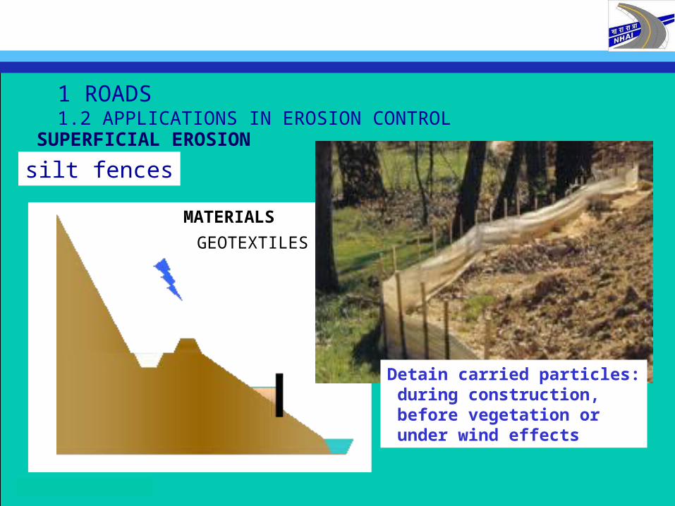
1 ROADS 1.2 APPLICATIONS IN EROSION CONTROL
MATERIALS
GEOTEXTILES
Detain carried particles: during construction, before vegetation or under wind effects
SUPERFICIAL EROSION
silt fences
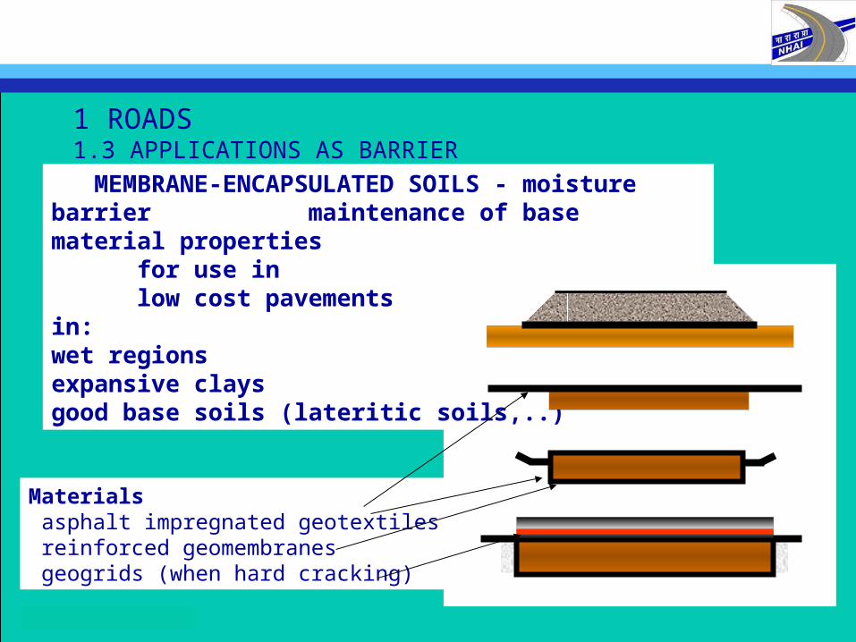
1 ROADS 1.3 APPLICATIONS AS BARRIER
MEMBRANE-ENCAPSULATED SOILS - moisture barrier maintenance of base material properties
for use inlow cost pavements
in:wet regionsexpansive claysgood base soils (lateritic soils,..)
Materials asphalt impregnated geotextiles reinforced geomembranes geogrids (when hard cracking)
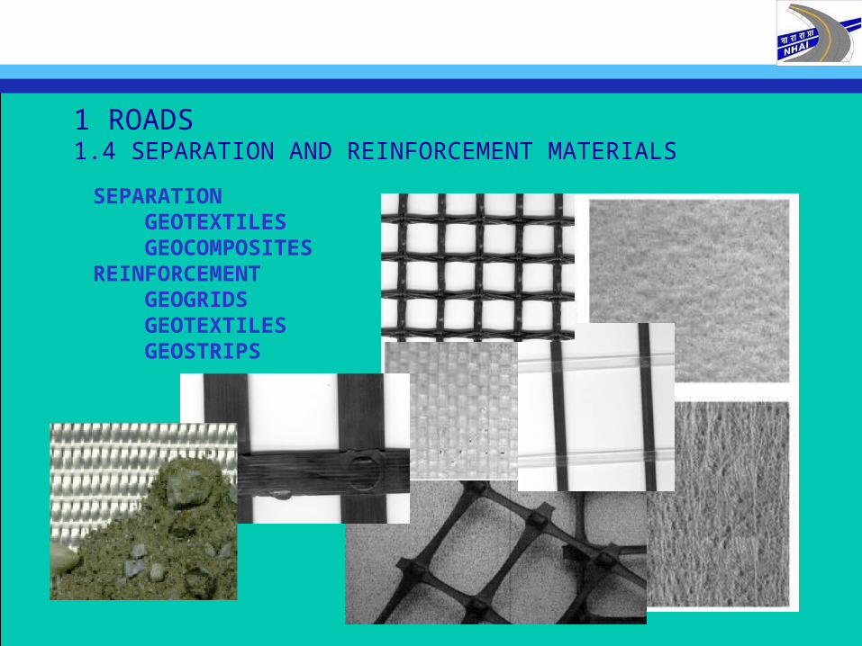
1 ROADS 1.4 SEPARATION AND REINFORCEMENT MATERIALS
SEPARATION GEOTEXTILES GEOCOMPOSITESREINFORCEMENT GEOGRIDS GEOTEXTILES GEOSTRIPS
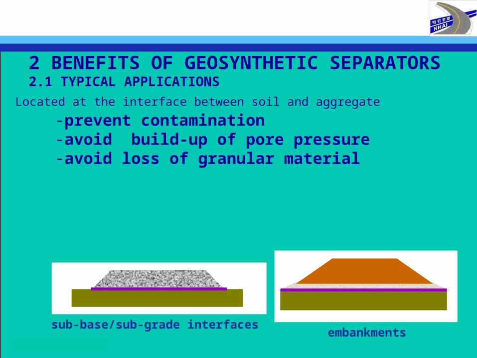
2 BENEFITS OF GEOSYNTHETIC SEPARATORS2.1 TYPICAL APPLICATIONS
-prevent contamination-avoid build-up of pore pressure-avoid loss of granular material
Located at the interface between soil and aggregate
sub-base/sub-grade interfacesembankments
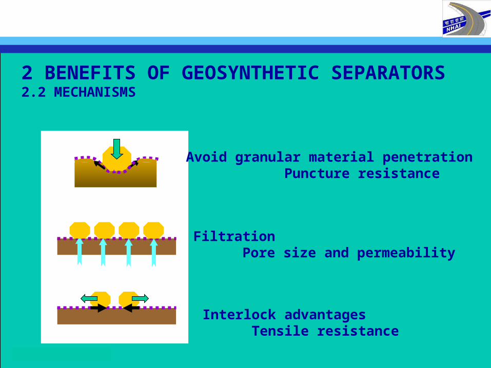
2 BENEFITS OF GEOSYNTHETIC SEPARATORS2.2 MECHANISMS
Avoid granular material penetration Puncture resistance
FiltrationPore size and permeability
Interlock advantages Tensile resistance
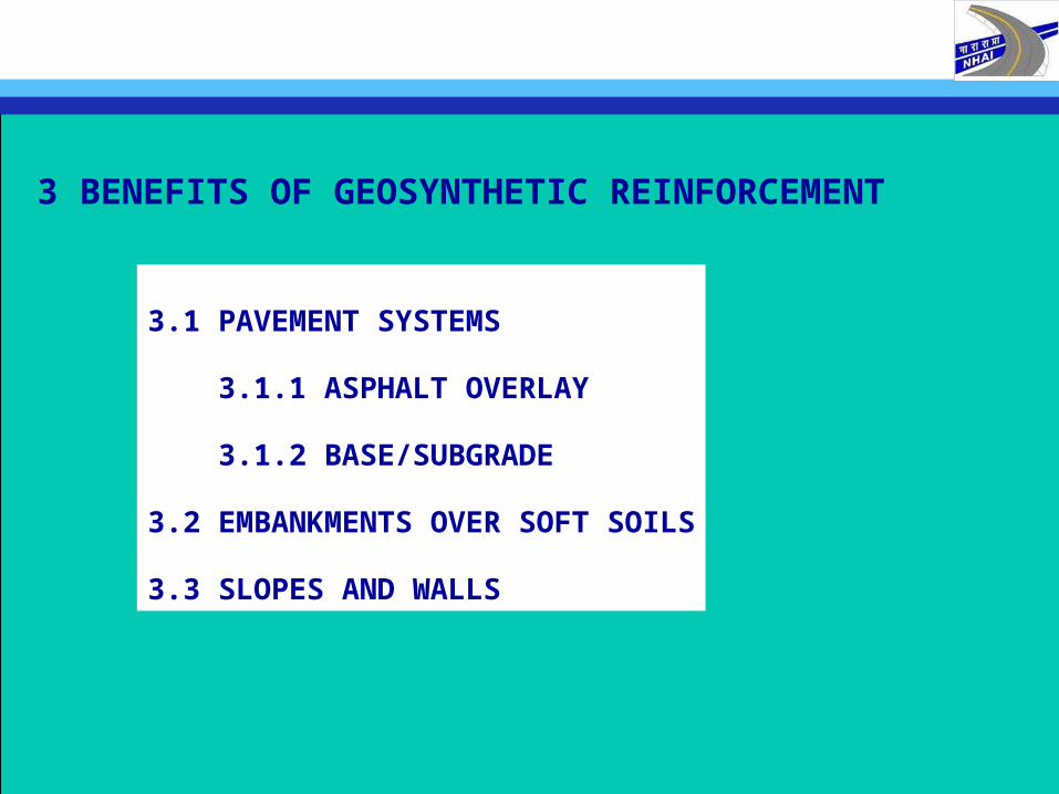
3 BENEFITS OF GEOSYNTHETIC REINFORCEMENT
3.1 PAVEMENT SYSTEMS
3.1.1 ASPHALT OVERLAY
3.1.2 BASE/SUBGRADE
3.2 EMBANKMENTS OVER SOFT SOILS
3.3 SLOPES AND WALLS
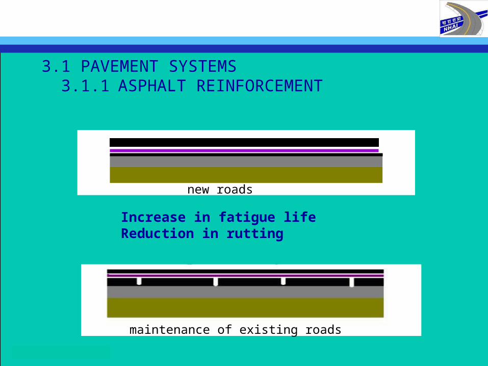
3.1 PAVEMENT SYSTEMS 3.1.1 ASPHALT REINFORCEMENT
new roads
maintenance of existing roads
Increase in fatigue lifeReduction in rutting
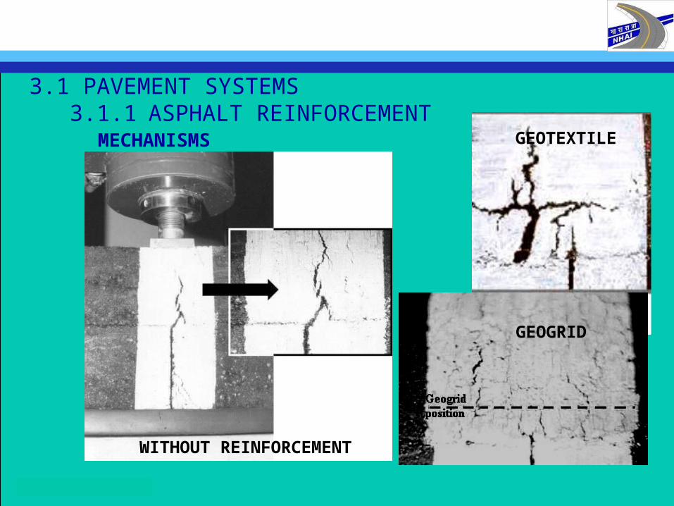
3.1 PAVEMENT SYSTEMS 3.1.1 ASPHALT REINFORCEMENT
MECHANISMS GEOTEXTILE
GEOGRID
WITHOUT REINFORCEMENT
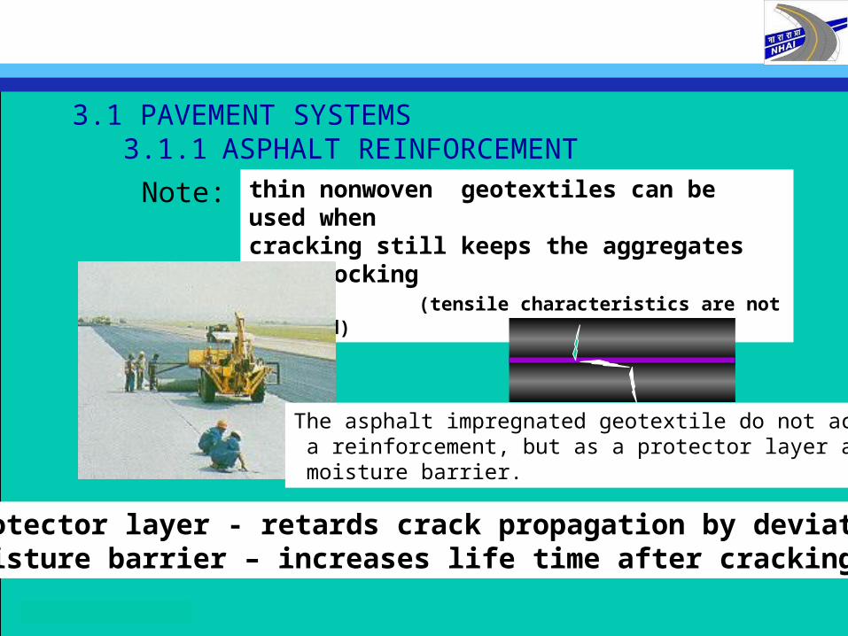
3.1 PAVEMENT SYSTEMS 3.1.1 ASPHALT REINFORCEMENT
thin nonwoven geotextiles can be used when cracking still keeps the aggregates interlocking
(tensile characteristics are not required)
protector layer - retards crack propagation by deviationmoisture barrier – increases life time after cracking
Note:
The asphalt impregnated geotextile do not acts as a reinforcement, but as a protector layer and a moisture barrier.
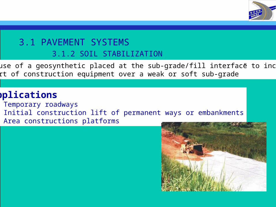
3.1 PAVEMENT SYSTEMS 3.1.2 SOIL STABILIZATION
“The use of a geosynthetic placed at the sub-grade/fill interface to increase thesupport of construction equipment over a weak or soft sub-grade”
Applications Temporary roadways Initial construction lift of permanent ways or embankments Area constructions platforms
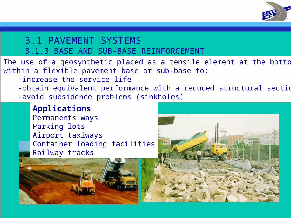
3.1 PAVEMENT SYSTEMS3.1.3 BASE AND SUB-BASE REINFORCEMENT
The use of a geosynthetic placed as a tensile element at the bottom or within a flexible pavement base or sub-base to:
-increase the service life -obtain equivalent performance with a reduced structural section-avoid subsidence problems (sinkholes)
ApplicationsPermanents waysParking lotsAirport taxiwaysContainer loading facilitiesRailway tracks

3.1 PAVEMENT SYSTEMS 3.1.4 ADVANTAGES
-cost savings in construction and maintenance
-increase of service life
-decrease or eliminate over-excavation and required granular fill
“in pavements systems, life cycle cost analysis are important
to show additional maintenance cost savings”
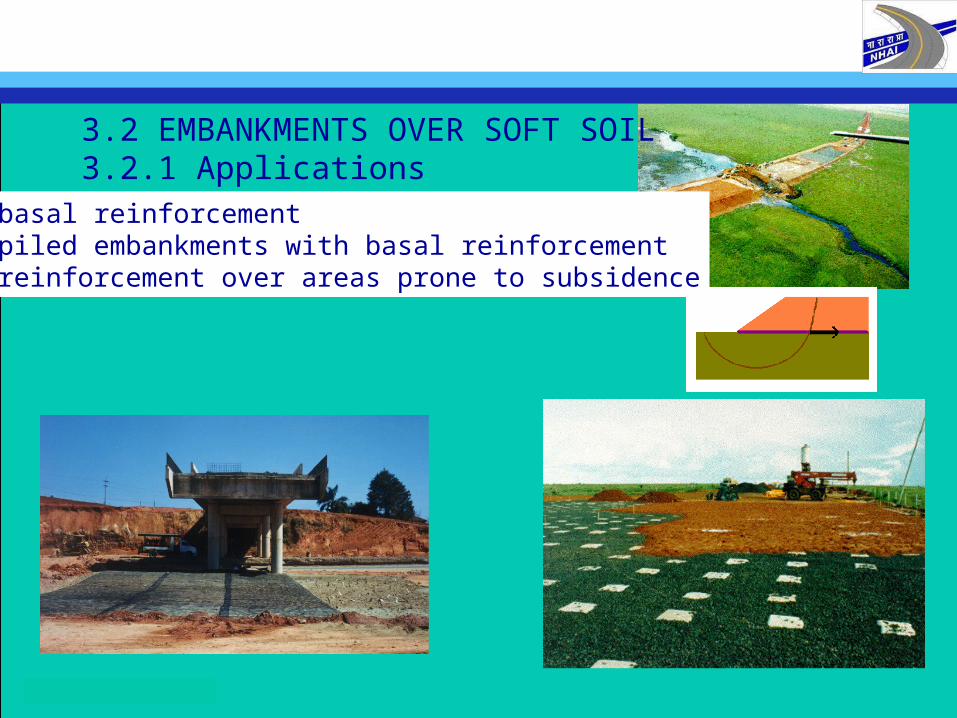
3.2 EMBANKMENTS OVER SOFT SOIL3.2.1 Applications
-basal reinforcement-piled embankments with basal reinforcement-reinforcement over areas prone to subsidence
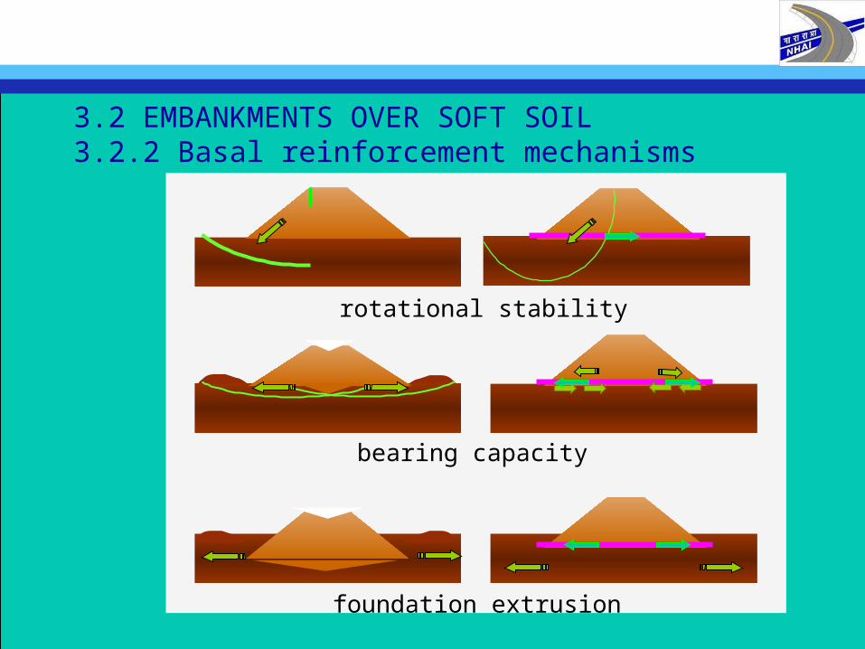
3.2 EMBANKMENTS OVER SOFT SOIL3.2.2 Basal reinforcement mechanisms
foundation extrusion
bearing capacity
rotational stability
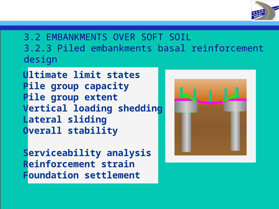
3.2 EMBANKMENTS OVER SOFT SOIL3.2.3 Piled embankments basal reinforcement design
Ultimate limit statesPile group capacityPile group extentVertical loading sheddingLateral slidingOverall stability
Serviceability analysisReinforcement strainFoundation settlement
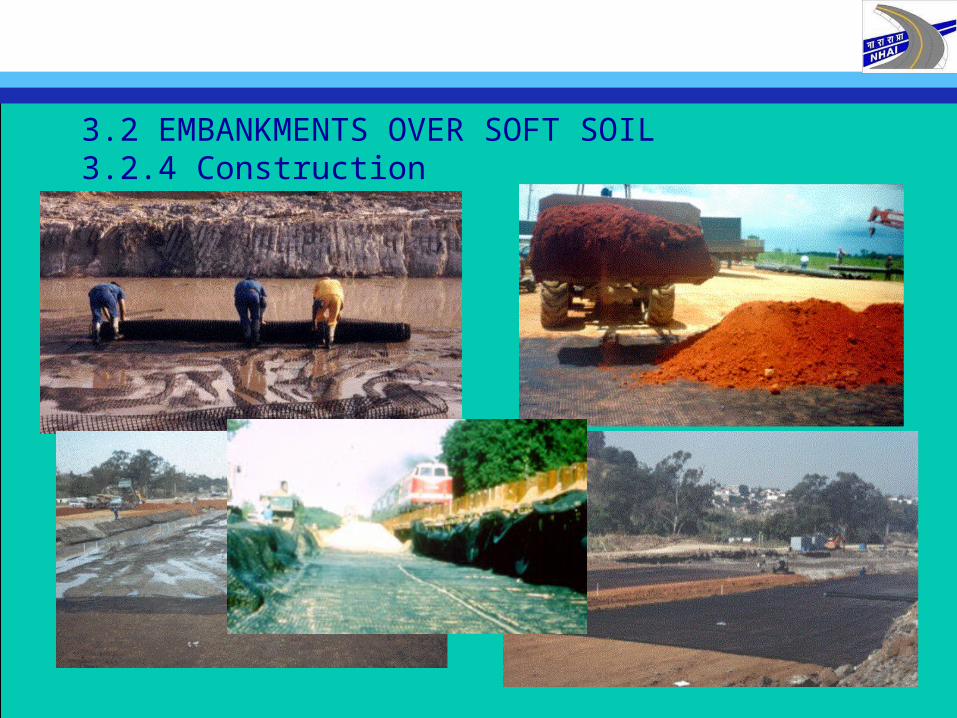
3.2 EMBANKMENTS OVER SOFT SOIL3.2.4 Construction

3.3 REINFORCED SLOPES AND WALLS3.3.1 applications
landslide reparationbridge abutmentincrease working areareduce filled area reduce filling material
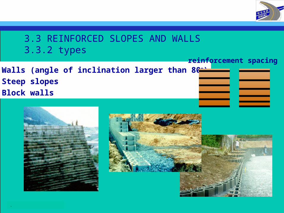
3.3 REINFORCED SLOPES AND WALLS3.3.2 types
Walls (angle of inclination larger than 80o)
Steep slopes
Block walls
.
reinforcement spacing
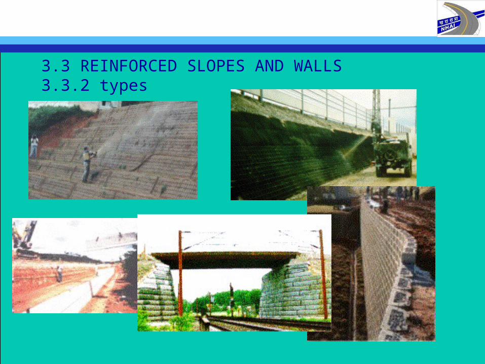
3.3 REINFORCED SLOPES AND WALLS3.3.2 types
3.3 REINFORCED SLOPES AND WALLS3.3.3 benefits
Economical solutions
Rapid and simple construction method
Allows construction in difficult terrain
Allows use of cheaper fill material
Satisfactory appearance structures
Environmental:
reduce damaged areas and
reduce natural material extracting
4. REQUIREMENTS AND TECHNICAL PROPERTIES
Mainly mechanical characteristics
Tensile strength (ISO 10319)Seam tensile strength (ISO 10321)Puncture resistance (ISO 12236)Impact test (ISO 13433)
Mainly hydraulic characteristics (for separation)Opening size (ISO 12959)Permeability normal to the plane (ISO 11058)
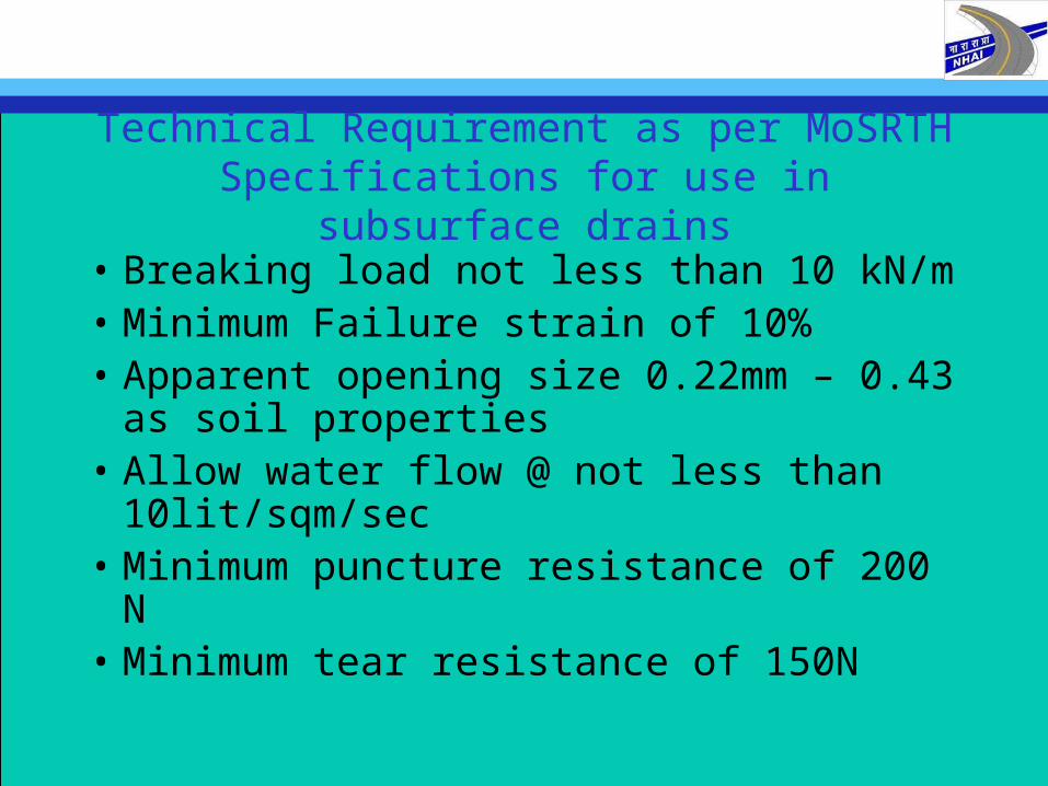
Technical Requirement as per MoSRTH Specifications for use in subsurface drains
• Breaking load not less than 10 kN/m • Minimum Failure strain of 10%• Apparent opening size 0.22mm – 0.43 as
soil properties• Allow water flow @ not less than
10lit/sqm/sec• Minimum puncture resistance of 200 N• Minimum tear resistance of 150N
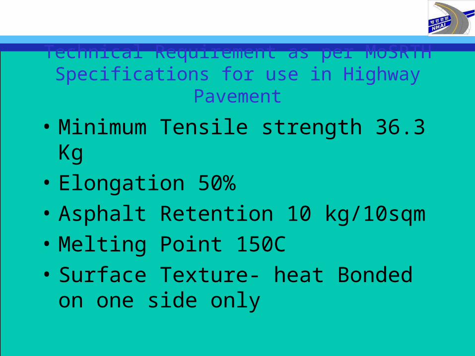
Technical Requirement as per MoSRTH Specifications for use in Highway Pavement
• Minimum Tensile strength 36.3 Kg
• Elongation 50%
• Asphalt Retention 10 kg/10sqm
• Melting Point 150C
• Surface Texture- heat Bonded on one side only
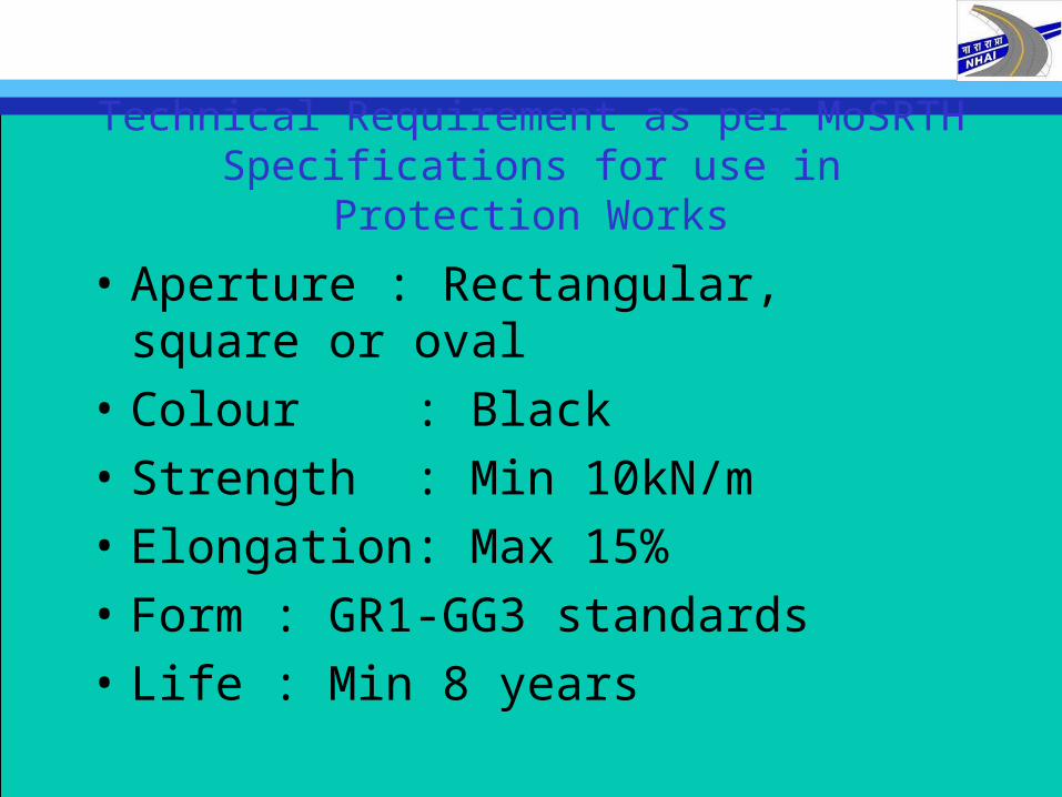
Technical Requirement as per MoSRTH Specifications for use in Protection Works
• Aperture : Rectangular, square or oval
• Colour : Black
• Strength : Min 10kN/m
• Elongation: Max 15%
• Form : GR1-GG3 standards
• Life : Min 8 years
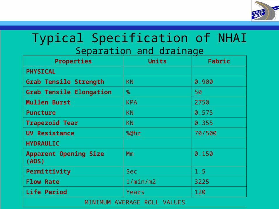
Typical Specification of NHAISeparation and drainage
Properties Units Fabric
PHYSICAL
Grab Tensile Strength KN 0.900
Grab Tensile Elongation % 50
Mullen Burst KPA 2750
Puncture KN 0.575
Trapezoid Tear KN 0.355
UV Resistance %@hr 70/500
HYDRAULIC
Apparent Opening Size (AOS) Mm 0.150
Permittivity Sec 1.5
Flow Rate 1/min/m2 3225
Life Period Years 120
MINIMUM AVERAGE ROLL VALUES
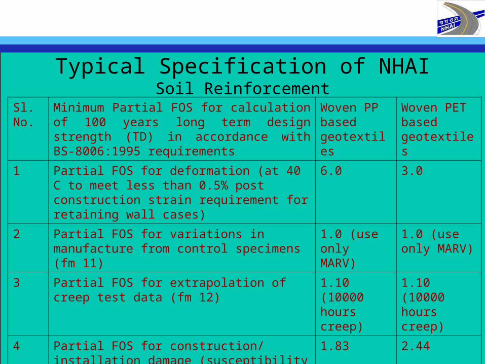
Typical Specification of NHAISoil Reinforcement
Sl. No.
Minimum Partial FOS for calculation of 100 years long term design strength (TD) in accordance with BS-8006:1995 requirements
Woven PP based geotextiles
Woven PET based geotextiles
1 Partial FOS for deformation (at 40 C to meet less than 0.5% post construction strain requirement for retaining wall cases)
6.0 3.0
2 Partial FOS for variations in manufacture from control specimens (fm 11)
1.0 (use only MARV)
1.0 (use only MARV)
3 Partial FOS for extrapolation of creep test data (fm 12)
1.10 (10000 hours creep)
1.10 (10000 hours creep)
4 Partial FOS for construction/ installation damage (susceptibility to damage) [fm 21]
1.83 2.44
5 Partial FOS for potential chemical (at 40 C) and biological degradation. (Environment) [fm 22]
1.10 1.15
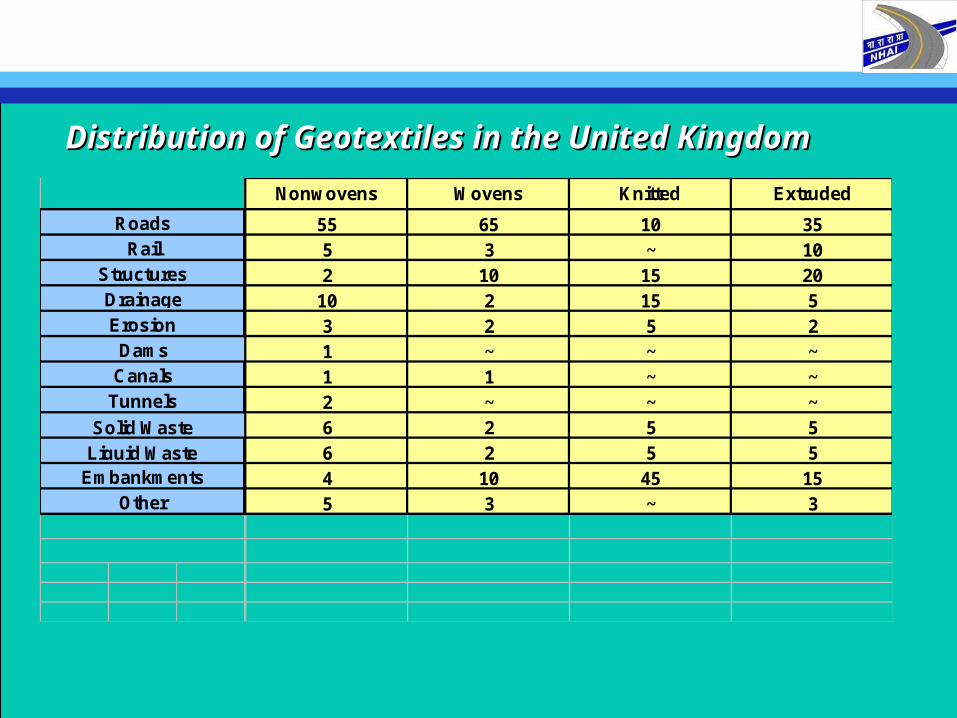
Distribution of Geotextiles in the United KingdomDistribution of Geotextiles in the United Kingdom
Nonwovens Wovens Knitted Extruded
55 65 10 355 3 ~ 102 10 15 20
10 2 15 53 2 5 21 ~ ~ ~1 1 ~ ~2 ~ ~ ~6 2 5 56 2 5 54 10 45 155 3 ~ 3
DamsCanals
Tunnels
RoadsRail
StructuresDrainage
Solid WasteLiquid Waste
EmbankmentsOther
Erosion
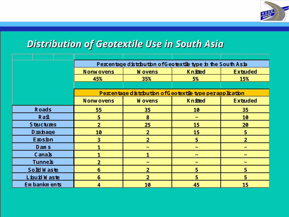
Distribution of Geotextile Use in South AsiaDistribution of Geotextile Use in South Asia
Nonwovens Wovens Knitted Extruded45% 35% 5% 15%
Nonwovens Wovens Knitted Extruded
55 35 10 355 8 ~ 102 25 15 20
10 2 15 53 2 5 21 ~ ~ ~1 1 ~ ~2 ~ ~ ~6 2 5 56 2 5 54 10 45 15
Percentage distribution of Geotextile type in the South Asia
Percentage distribution of Geotextile type per application
Solid WasteLiquid Waste
Embankments
ErosionDams
CanalsTunnels
RoadsRail
StructuresDrainage
History of Geotextiles in IndiaHistory of Geotextiles in India• Used commercially since early ’80s• However, during ’80 – ’90 the use was restricted to separation,
filtration and drainage application for both non-woven and woven type
• Indian manufacturer like Hitkari, Tata Mills etc. participated in production of non-woven type for civil engineering application
• Major boost in usage came after 1995 with major ports and highway development projects.
• Application included marine protection below rip-raps and armour layers for separation and filtration for land reclamation projects.
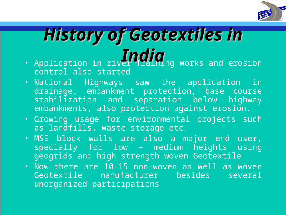
• Application in river Training works and erosion control also started
• National Highways saw the application in drainage, embankment protection, base course stabilization and separation below highway embankments, also protection against erosion.
• Growing usage for environmental projects such as landfills, waste storage etc.
• MSE block walls are also a major end user, specially for low – medium heights using geogrids and high strength woven Geotextile
• Now there are 10-15 non-woven as well as woven Geotextile manufacturer besides several unorganized participations
History of Geotextiles in IndiaHistory of Geotextiles in India
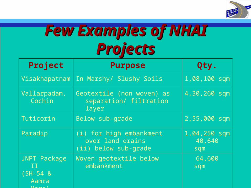
Few Examples of NHAI ProjectsFew Examples of NHAI Projects
Project Purpose Qty.
Visakhapatnam In Marshy/ Slushy Soils 1,08,100 sqm
Vallarpadam, Cochin
Geotextile (non woven) as separation/ filtration layer
4,30,260 sqm
Tuticorin Below sub-grade 2,55,000 sqm
Paradip (i) for high embankment over land drains
(ii) below sub-grade
1,04,250 sqm 40,640 sqm
JNPT Package II(SH-54 & Aamra
Marg)
Woven geotextile below embankment
64,600 sqm

THANK YOU FOR YOUR ATTENTIONTHANK YOU FOR YOUR ATTENTION