Embed Size (px)
Citation preview
Training Systems for Power ElectronicsThe Key Technology for Electrical Drives –Multimedia Learning, Experimenting, Programmingand Researching
Connection via USB and LN-Toolbox to Matlab®/Simulink®
Drive Technology
2
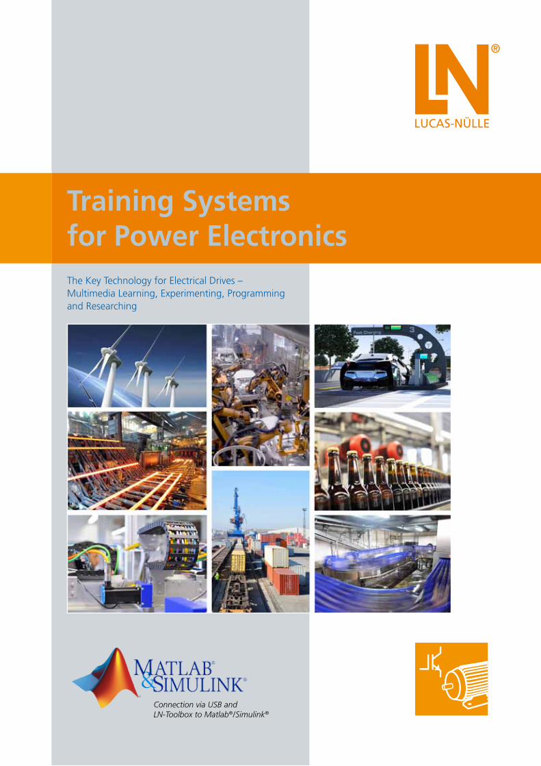
Making Power Electronics Understandable
The key role of power electronics
Modern development and analysis tools for electrical drive technology
As part of the energy revolution, power electronics has assumed
a key role as an interdisciplinary technology, with variable fre-
quency drives capable of achieving enormous potential savings.
Even more significant are the changes taking place in the field
of automotive technology, as electric vehicles are poised to play
an ever increasing role in shaping the future of road transport.
The deployment of power electronics must be competently
prepared and implemented to ensure that potential efficiencies
do not get ignored or anticipated savings remain untapped due
to incorrect parameterization.
Industry is placing rising demands on the qualifications and
know-how of electronics specialists, technicians and engineers –
know-how which makes it possible to recognize potential
efficiencies, create plans, as well as expertly handle, connect and
parameterize power electronics systems and equipment. As
a result, training that is both practical and project oriented is
expected, covering the entire range of vocational needs right
through to engineering level.
To cope with technological change, the industry is looking for
highly qualified and skilled engineers who not only possess the
actual expertise required but are also familiar with contemporary,
efficient tools and capable of using them too. The Matlab®/
Simulink® programming language has established itself
worldwide as a standard for scientific and engineering
calculations and simulations.
This high-level language and its interactive environment for
numerical computations, visualization and programming enables
extremely fast development cycles for variable-speed drives
which are currently experiencing tremendous demand thanks
especially to the need for electric mobility.
Handling these tools is complex, and must be taught and
learned in a practical manner, particularly in conjunction with
test benches and “hardware in the loop”. In this regard, the
world’s universities bear a major responsibility for training
engineers in the skills required by industry.
Lucas-Nülle

Drive Technology
3
Learning and understanding the basics of power electronics and drive technology
Expand the training system to a programmable, rapid prototyping system for drive technology
The modular, blended-learning training system for power electro-
nics and drive technology makes learning and experimenting very
simple and effective. Various basic and advanced equipment sets
permit sophisticated, exciting experiments to be conducted and
knowledge to be conveyed in a highly efficient manner leading to
the acquisition of practical skills and competence. Starting with
the transistor as a switch and progressing through modulation
methods right up to variable-speed DC and three-phase drives,
ILA interactive experiment manuals are available on all of the
relevant subjects. Animations help understand complex theory,
while proven guidelines and intrinsically safe devices make expe-
rimentation in project-oriented training a simple matter. Virtual
instruments integrated into the course can be used to visualize
actual measured values or to control the inverter.
Your drive’s control unit can be freely programmed via the
programming interface. The LN-Toolbox can be used to rapidly
simulate complex, variable-speed drives in Matlab®/Simulink®,
and then program the control unit with automatically generated
code. Under variable loads, the system can be subjected to com-
plex analyses with the help of advanced tools. Matlab®/Simulink®
is already being used by educational institutions around the
world. Supplemented by the power electronics training system,
this environment now also enables a comprehensive approach
for training engineers in the areas of power electronics and drive
technology.
Your benefits
• Compact, easily operable, intrinsically safe system
• Integrated measurement and time-based display of electrical variables
• Can be extended to fully operational drive systems with electrical machines of the 300W and 1kW classes
Your benefits
• Fast prototyping system for power electronics
• A special Matlab®/Simulink® toolbox allows easy hardware access
• Data visualization in real time
• The same Matlab® model is employed for simulation and code generation for hardware
Lucas-Nülle

Drive Technology
4
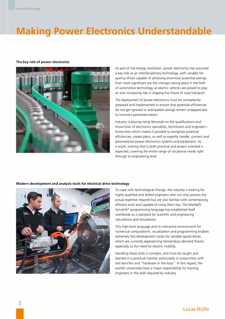
Components
Three-phase isolation transformer
Drive machines
Control unit: Self-commutated converter
1 Input voltage range: 47 to 3x 230V
2 Integrated input filter
3 Integrated brake chopper with a powerful 300W resistor
4 DSP-controlled driving and measuring unit, integrated measurement of 6 voltages and 3 currents, display of operating states
5 Intuitive user operation by means of a control dial and pushbuttons
6 CAN-bus port for networking drive systems
7 Analog input: + / - 10V
Serving as a power supply unit in all power
electronics experiments, the isolation transformer
optimizes protection during experiments by
virtue of its galvanic isolation.
• Output voltage: 3x 94V with centre tap (47V)
• Power: 300VA/1000VA for operation with
300W/1kW machines
• Thermo-magnetic overload protection
1
2
3
4
5
6
7
9
8
All machines in the 300W and 1kW classes can be connected to the power
electronics system. Thus, the following drives can be realized:
• Variable-speed DC drive
• Frequency converter drive with asynchronous motor
• Electronically commutated drive
• Servo-drive with synchronous servo-motor
The drives can be investigated and optimized conveniently by means of the
servo-machine test stand.
Lucas-Nülle
Drive Technology
5
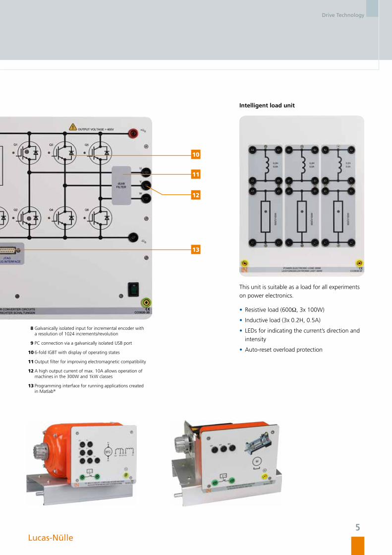
Intelligent load unit
8 Galvanically isolated input for incremental encoder with a resolution of 1024 increments/revolution
9 PC connection via a galvanically isolated USB port
10 6-fold IGBT with display of operating states
11 Output filter for improving electromagnetic compatibility
12 A high output current of max. 10A allows operation of machines in the 300W and 1kW classes
13 Programming interface for running applications created in Matlab®
This unit is suitable as a load for all experiments
on power electronics.
• Resistive load (600Ω, 3x 100W)
• Inductive load (3x 0.2H, 0.5A)
• LEDs for indicating the current’s direction and
intensity
• Auto-reset overload protection
10
11
12
13
Lucas-Nülle
Drive Technology
6
Self-Commutated Converter Circuits
Training System
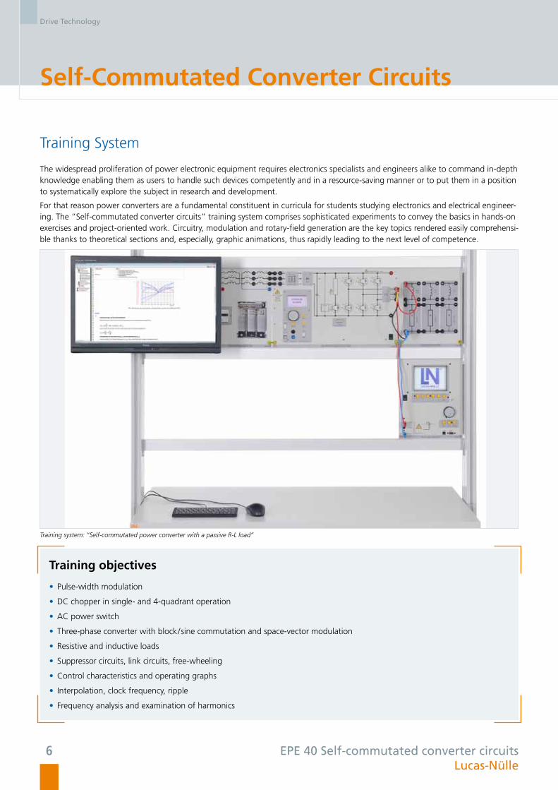
The widespread proliferation of power electronic equipment requires electronics specialists and engineers alike to command in-depth knowledge enabling them as users to handle such devices competently and in a resource-saving manner or to put them in a position to systematically explore the subject in research and development.
For that reason power converters are a fundamental constituent in curricula for students studying electronics and electrical engineer-ing. The “Self-commutated converter circuits” training system comprises sophisticated experiments to convey the basics in hands-on exercises and project-oriented work. Circuitry, modulation and rotary-field generation are the key topics rendered easily comprehensi-ble thanks to theoretical sections and, especially, graphic animations, thus rapidly leading to the next level of competence.
Training system: “Self-commutated power converter with a passive R-L load”
Training objectives
• Pulse-width modulation
• DC chopper in single- and 4-quadrant operation
• AC power switch
• Three-phase converter with block/sine commutation and space-vector modulation
• Resistive and inductive loads
• Suppressor circuits, link circuits, free-wheeling
• Control characteristics and operating graphs
• Interpolation, clock frequency, ripple
• Frequency analysis and examination of harmonics
EPE 40 Self-commutated converter circuitsLucas-Nülle
Drive Technology
7
Interactive Learning Environment
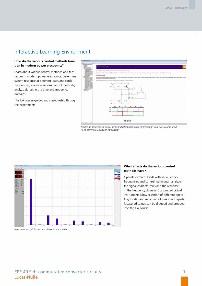
How do the various control methods func-tion in modern power electronics?
Learn about various control methods and tech-
niques in modern power electronics. Determine
system response at different loads and clock
frequencies; examine various control methods;
analyze signals in the time and frequency
domains.
The ILA course guides you step-by-step through
the experiments.
Switching sequence of power semiconductors with block commutation in the ILA course titled “Self-commutated power converters”
Harmonics analysis in the case of block commutation
What effects do the various control methods have?
Operate different loads with various clock
frequencies and control techniques; analyze
the signal characteristics and the response
in the frequency domain. Customized virtual
instruments allow selection of different opera-
ting modes and recording of measured signals.
Measured values can be dragged and dropped
into the ILA course.
EPE 40 Self-commutated converter circuitsLucas-Nülle
Drive Technology
8
Frequency Converter Drives
Training System
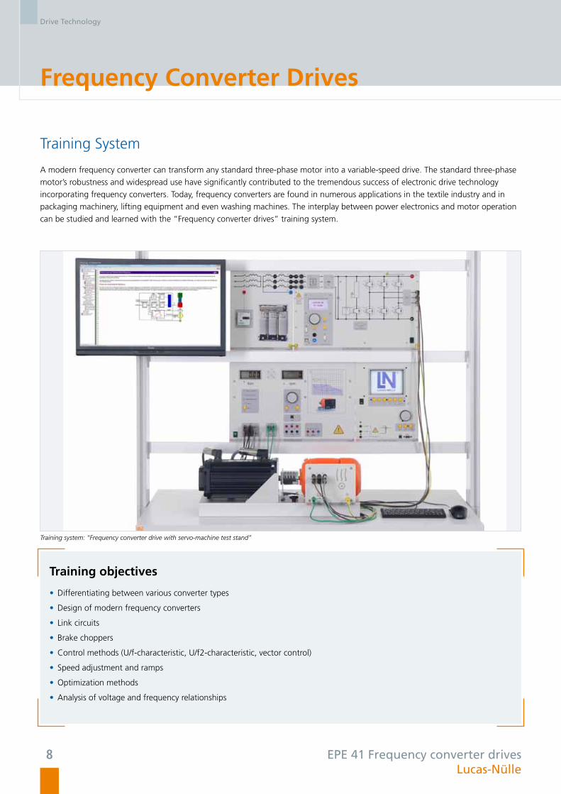
A modern frequency converter can transform any standard three-phase motor into a variable-speed drive. The standard three-phase
motor’s robustness and widespread use have significantly contributed to the tremendous success of electronic drive technology
incorporating frequency converters. Today, frequency converters are found in numerous applications in the textile industry and in
packaging machinery, lifting equipment and even washing machines. The interplay between power electronics and motor operation
can be studied and learned with the “Frequency converter drives” training system.
Training system: “Frequency converter drive with servo-machine test stand”
Training objectives
• Differentiating between various converter types
• Design of modern frequency converters
• Link circuits
• Brake choppers
• Control methods (U/f-characteristic, U/f2-characteristic, vector control)
• Speed adjustment and ramps
• Optimization methods
• Analysis of voltage and frequency relationships
EPE 41 Frequency converter drivesLucas-Nülle

Drive Technology
9
Interactive Learning Environment
How are various operating points set?
Learn how a frequency converter’s frequency
and output voltage influence speed, torque,
power and efficiency.
Determine the various operating points with
the help of the servo-machine test stand and
ActiveServo software. Lucid representations
make it possible to directly determine operating
behaviour.
The ILA course provides the necessary informa-
tion and guidelines to perform the hands-on
experiments.
Variable-speed pump drive
87Hz technology in the ILA course on frequency converter drives
What does 87Hz technology mean?
Drives with an extended control range are
important for certain applications. Thanks to
the converter’s design it is possible to use what
is known as 87Hz technology. In this case,
the converter’s control range is increased by a
combination of intelligent motor circuitry and
appropriate parameterization, without resulting
in any torque losses.
EPE 41 Frequency converter drivesLucas-Nülle
Drive Technology
10
Servo-Drives
Training System
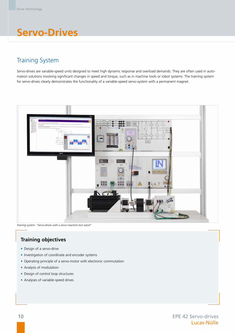
Servo-drives are variable-speed units designed to meet high dynamic response and overload demands. They are often used in auto-
mation solutions involving significant changes in speed and torque, such as in machine tools or robot systems. The training system
for servo-drives clearly demonstrates the functionality of a variable-speed servo-system with a permanent magnet.
Training objectives
• Design of a servo-drive
• Investigation of coordinate and encoder systems
• Operating principle of a servo-motor with electronic commutation
• Analysis of modulation
• Design of control loop structures
• Analyses of variable-speed drives
Training system: “Servo-drives with a servo-machine test stand”
EPE 42 Servo-drives Lucas-Nülle

Drive Technology
11
Interactive Learning Environment
How is a synchronous servo-motor designed?
The ILA course shows how modern servo-
motors are designed, how the various position
measurement systems function, and what
controller architecture is employed. Informative
illustrations and animations help investigate
functionality and mode of operation.
Layout of a synchronous servo-motor in the ILA course on servo-drives
Space-vector control of the servo-motor
What is load commutation?
Control power semiconductors via rotor posi tion,
and learn how various parameters influence
speed and torque.
Optimize the drive’s properties using virtual
instruments, and examine the drive’s behaviour
using the servo-machine test stand.
EPE 42 Servo-drives Lucas-Nülle
Drive Technology
12
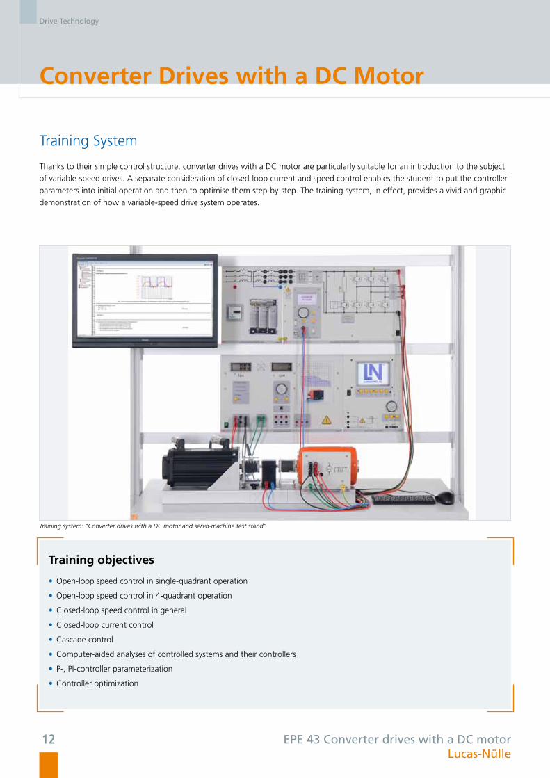
Converter Drives with a DC Motor
Training System
Thanks to their simple control structure, converter drives with a DC motor are particularly suitable for an introduction to the subject
of variable-speed drives. A separate consideration of closed-loop current and speed control enables the student to put the controller
parameters into initial operation and then to optimise them step-by-step. The training system, in effect, provides a vivid and graphic
demonstration of how a variable-speed drive system operates.
Training objectives
• Open-loop speed control in single-quadrant operation
• Open-loop speed control in 4-quadrant operation
• Closed-loop speed control in general
• Closed-loop current control
• Cascade control
• Computer-aided analyses of controlled systems and their controllers
• P-, PI-controller parameterization
• Controller optimization
Training system: “Converter drives with a DC motor and servo-machine test stand”
EPE 43 Converter drives with a DC motorLucas-Nülle
Drive Technology
13
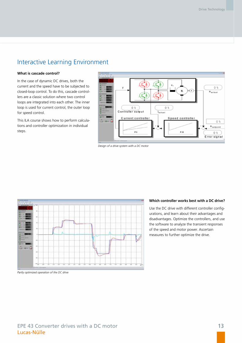
Interactive Learning Environment
What is cascade control?
In the case of dynamic DC drives, both the
current and the speed have to be subjected to
closed-loop control. To do this, cascade control-
lers are a classic solution where two control
loops are integrated into each other. The inner
loop is used for current control, the outer loop
for speed control.
This ILA course shows how to perform calcula-
tions and controller optimization in individual
steps.
Design of a drive system with a DC motor
Partly optimized operation of the DC drive
Which controller works best with a DC drive?
Use the DC drive with different controller config-
urations, and learn about their advantages and
disadvantages. Optimize the controllers, and use
the software to analyze the transient responses
of the speed and motor power. Ascertain
measures to further optimize the drive.
EPE 43 Converter drives with a DC motor Lucas-Nülle
Drive Technology
14
Model-Based Development of Drives with Matlab®/Simulink®
Nearly all electrical drives such as those used in industrial plants and electric vehicles incorporate three-phase technology. The auto-
matic control of such drives, for instance, to ensure smooth start-up or measured acceleration, entails mathematically complex and
elaborate programming. Implementation is therefore often characterized by very long development times.
A newly created toolbox will in future make it possible to simulate complex controller structures for three-phase drives with Matlab®/
Simulink® in advance, and subsequently test them on a real converter with a motor and load by means of automatically generated code.
Your benefits• Safe handling thanks to intrinsically safe hardware
(all protective functions are implemented independently
of software)
• Promotion of a deeper understanding of a complex subject,
e.g. in education and training, or through use of the tool-
box in laboratory programs accompanying theory
• Very rapid, model-based, parameterizable software gene-
ration for own controllers in conjunction with industrial
applications
• Pursuit of new methods of research on rotary-field drives,
e.g. control using state-space methods, condition moni-
toring for errors, sensorless automatic speed control using
new observational techniques
• Impressive design possibilities for closed-loop control of
three-phase drives
• Creation of complex algorithms using fast control cycles of
125 μs
• P-, PI-controller parameterization
• Controller optimization
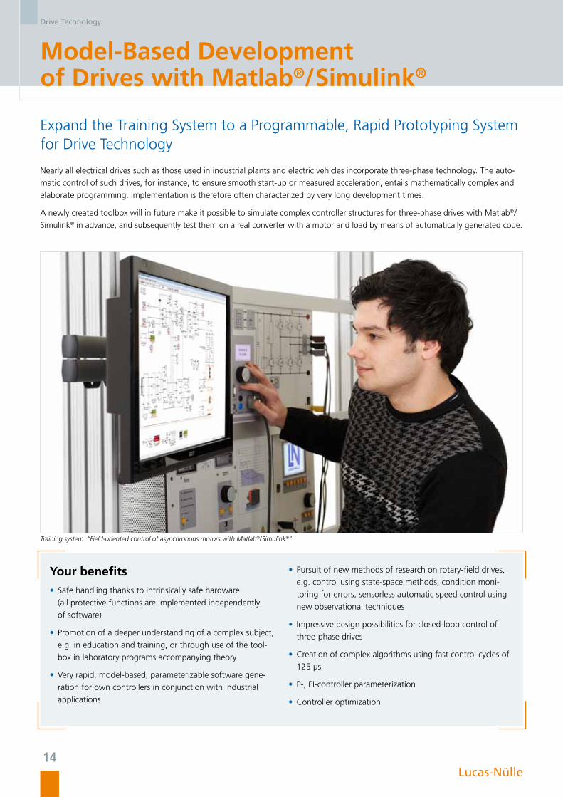
Training system: “Field-oriented control of asynchronous motors with Matlab®/Simulink®”
Expand the Training System to a Programmable, Rapid Prototyping System for Drive Technology
Lucas-Nülle

Drive Technology
15
Quicker results with the Matlab® toolbox
A toolbox adapted to the power electronics
hardware enables rapid implementation of
one’s own applications. Special templates allow
simple introduction by configuring the system
so that only a few adjustments still need to be
made by the user. The toolbox provides users
with all the necessary modules for controlling
hardware-related functions, as well as blocks
for fast transformations and controllers. The
system can be extended at will by adding one’s
own library elements to those of the Matlab®/
Simulink®.
Special toolbox for the training system
Graphic user interface in the Matlab® environment
Hardware connection via Matlab® Scope
A special graphic dialog serves to establish the
connection between Matlab® and hardware
via a USB interface. The time characteristics of
all internal variables can be visualized during
runtime. A number of different time resolutions
and trigger options are available here. The
signals can be displayed in the time domain as
well as the frequency domain. The display can
be divided into two units, making it possible to
visualize up to ten signals simultaneously. Para-
meters such as those related to the controller
can be uploaded conveniently from the PC to
the hardware during runtime.
Lucas-Nülle
Drive Technology
16
Field-Oriented Control of Asynchronous Motors with Matlab®/Simulink®
Training System
Three-phase drives are used in almost all electrical drives today. The automatic control of such drives is a mathematically complex
and costly undertaking. With the help of a special toolbox for Matlab®/Simulink®, the training system makes it possible to simulate
complex control algorithms, and subsequently test them by means of automatically generated code on authentic, intrinsically safe
hardware incorporating a motor and load.
Training objectives
• Creation of an HIL system (hardware in the loop) under real-time conditions
• Modeling and design of field-oriented control on a continuous design level
• Discretization of control for operation on a DSP (digital signal processor)
• Creation and optimization of current and speed controllers
• Park and Clarke transformation
• Integration of space-vector modulation for optimal control of IGBTs
• Decoupling of field-oriented currents and voltages
• Speed detection via an incremental encoder
• Comparison of simulation results with real measurements
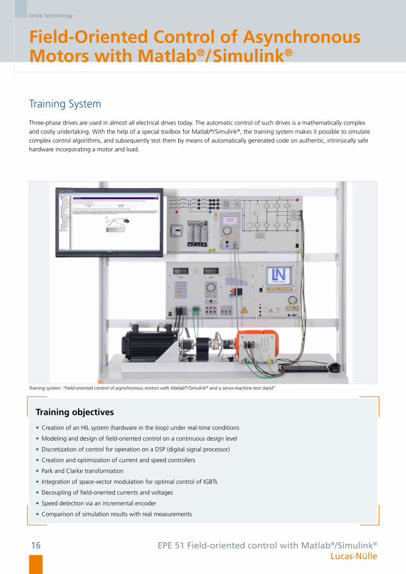
Training system: “Field-oriented control of asynchronous motors with Matlab®/Simulink® and a servo-machine test stand”
EPE 51 Field-oriented control with Matlab®/Simulink®
Lucas-Nülle

Drive Technology
17
Interactive Learning Environment
How does field-oriented control work?
Drives with field-oriented control are today
found in many machines. The high dynamics
and ample torque reserves characterize these
drive systems.
This ILA course guides you step by step through
the topic of field-oriented control. In addition to
the creation of the process control models, the
course also covers the testing and optimization
of the control loop.
ILA course: “Field-oriented control of asynchronous motors”
Field-oriented control of a three-phase motor
Simulation or real control? Decide for yourself.
A single Simulink® model forms the foundation
for simulation or functions as the program for
the actual hardware. It is only after completion
that the user chooses between simulation or
application in the real system. Accordingly, it is
possible during simulation to test and optimize
the control loop and then use the model to put
the actual hardware into operation. This proce-
dure guarantees rapid learning success. At the
same time the distinction between simulation
and real systems is clearly recognised.
EPE 51 Field-oriented control with Matlab®/Simulink® Lucas-Nülle
Drive Technology
18
Variable-Speed Permanent-Magnet Servo-Drives with Matlab®/Simulink®
Training System
Synchronous servo-motors are now used in many modern drives. In addition to dynamic response, energy efficiency is also playing
a major role. The training system permits in-depth investigations of existing control loop concepts thanks to the open programming
feature Matlab®/Simulink® and permits new approaches to be safely tested. For instance, the system can be used to create drives
typically employed in industry and the automotive sector.
Training objectives
• Creation of a HIL system under real-time conditions
• Modelling and design of an automatic servo control on a continuous design level
• Discretization of a closed-loop control for operation on a DSP
• Creation and optimization of current and speed controllers
• Park and Clarke transformation
• Integration of space-vector modulation for optimal control of IGBTs
• Decoupling of field-oriented currents and voltages
• Speed and position detection via an incremental encoder
• Comparison of simulation results with real measurements
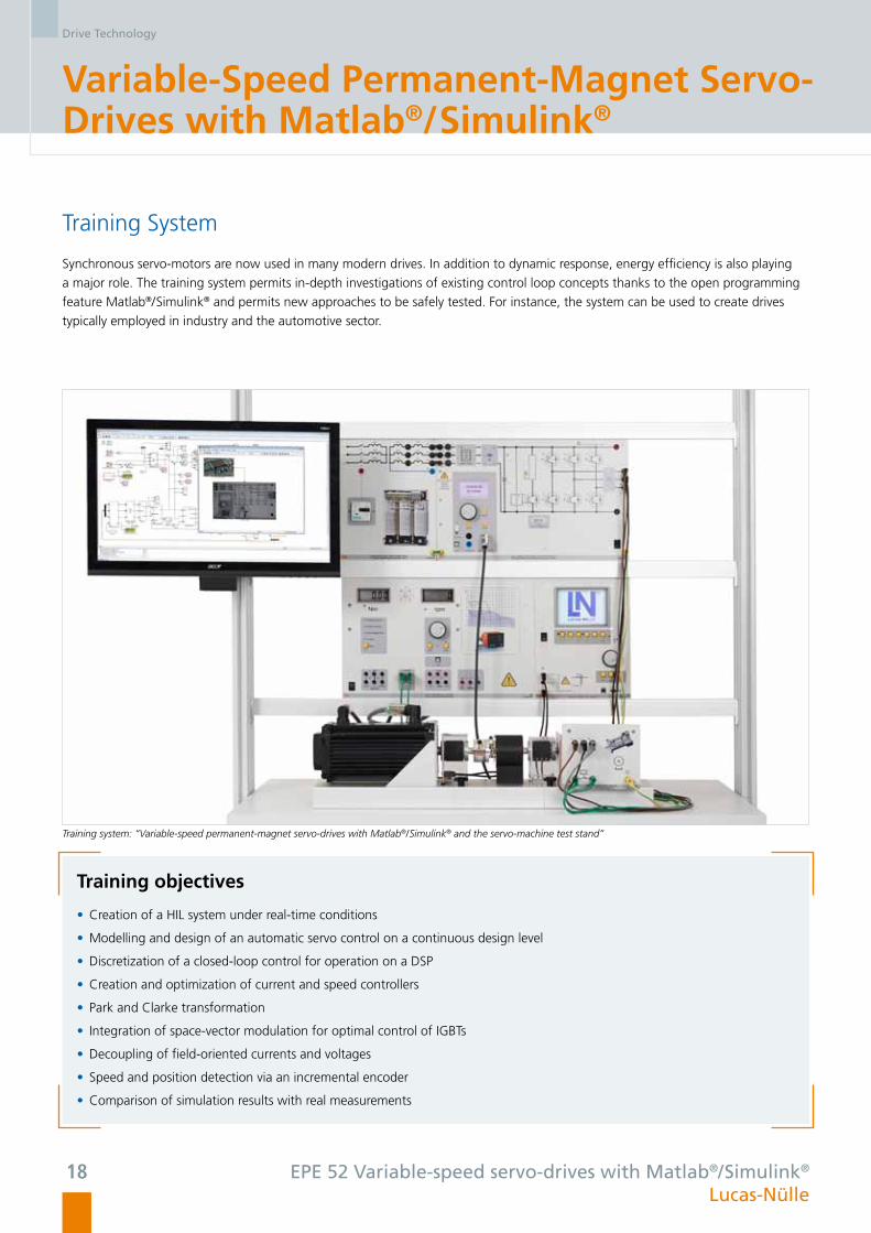
Training system: “Variable-speed permanent-magnet servo-drives with Matlab®/Simulink® and the servo-machine test stand”
EPE 52 Variable-speed servo-drives with Matlab®/Simulink®
Lucas-Nülle
Drive Technology
19
Interactive Learning Environment
How does a drive with a synchronous servo-motor operate?
Permanently-excited synchronous motors do not
work without corresponding control electronics.
Create a synchronous servo-drive and work your
way through this topic, starting with open-loop
control all the way to closed-loop control.
The ILA course guides you step by step, the
open system making it easy to implement
progressive concepts so that the drive can be
expanded according to your own ideas.
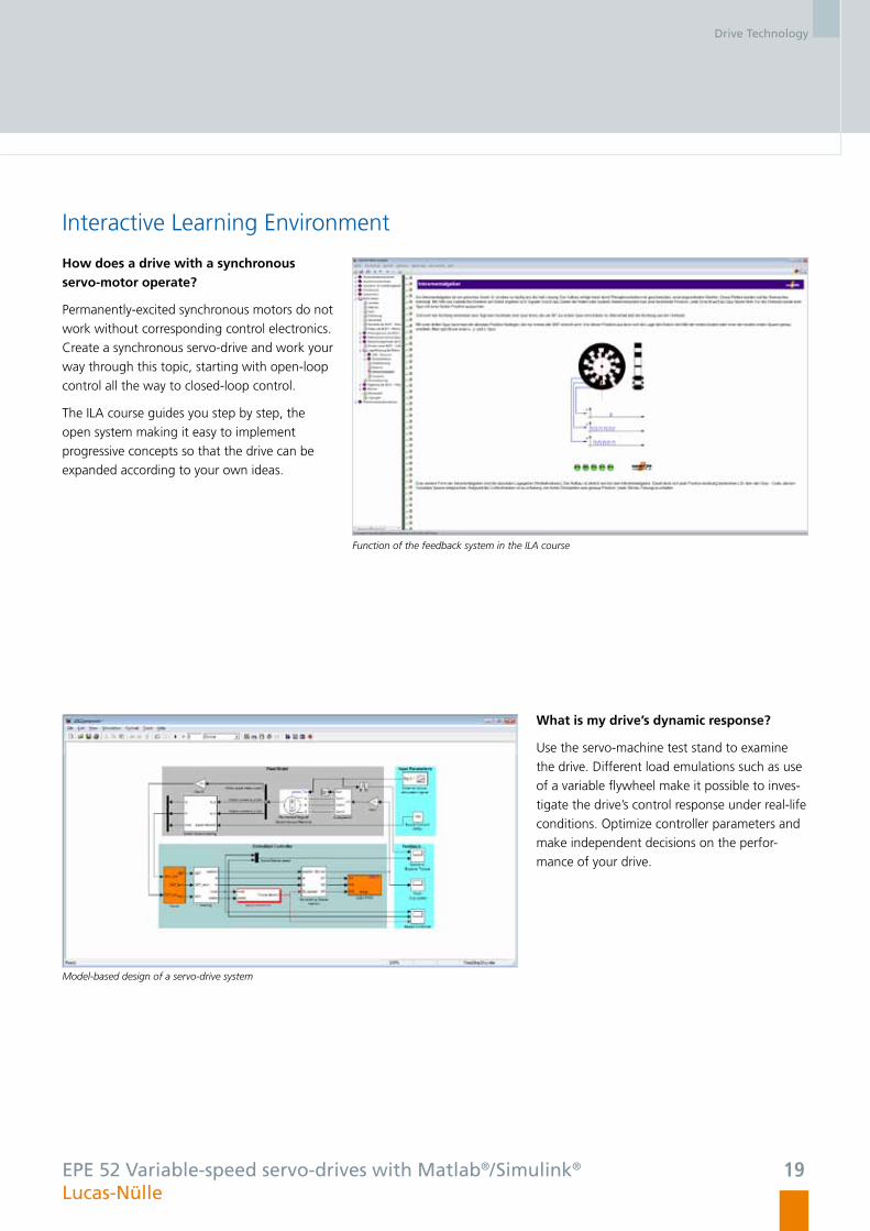
Function of the feedback system in the ILA course
Model-based design of a servo-drive system
What is my drive’s dynamic response?
Use the servo-machine test stand to examine
the drive. Different load emulations such as use
of a variable flywheel make it possible to inves-
tigate the drive’s control response under real-life
conditions. Optimize controller parameters and
make independent decisions on the perfor-
mance of your drive.
EPE 52 Variable-speed servo-drives with Matlab®/Simulink® Lucas-Nülle

Drive Technology
20
DC Drives with Cascade Control Using Matlab®/Simulink®
Training System
Thanks to their clearly arranged control structure, power converters with DC motors are particularly suitable for programming one‘s
own initial, own control algorithms. This training system permits implementation, optimization and operation of the student’s own
control configurations. Not only conventional approaches, but also new ideas and extensions can be tried out safely in the open
system.
Training objectives
• Creation of a HIL system under real-time conditions
• Modelling and design of cascade control loop for DC motors at the continuous design level
• Discretization of the control loop for operation on a DSP
• Creation and optimization of current and speed controllers
• Speed detection via an incremental encoder
• Comparison of simulation results with real measurements
Training system: “DC drives with cascaded control using Matlab®/Simulink® and a servo-machine test stand”
EPE 53 Variable-speed DC drives with Matlab®/Simulink®
Lucas-Nülle

Drive Technology
21
Interactive Learning Environment
How does a variable-speed DC drive work?
This ILA course provides practical examples to
demonstrate the design, configuration and
commissioning of DC drives. Current and speed
controllers are implemented and optimized step
by step. Direct application in control enginee-
ring models and work with real systems ensure
successful learning on a lasting basis.
Fundamentals of DC motors in the ILA course
Optimization of controller settings
How are controllers designed?
The training system can be used to test con-
troller design as part of simulations as well as
real environments. A graphic user interface op-
timizes access to the control variables’ dynamic
signals and thus permits rapid adjustments to
settings as well as their testing.
EPE 53 Variable-speed DC drives with Matlab®/Simulink® Lucas-Nülle

Drive Technology
22
Computer-Assisted Learning Environment
An Interactive Lab Assistant (ILA) supports you while you conduct the experiments. Besides serving as a guide through the experi-
ment procedures, this assistant provides valuable theoretical information and records readings. The necessary laboratory documenta-
tion is created as printed matter or PDF files automatically in the background.
If you want to customize the manuals, simply use the LabSoft Classroom Manager to revise or supplement the contents.
Your benefits
• Theoretical reference material
• Support in conducting experiments
• Clear representation of experiment setups
• Access to real instrumentation
• Integrated operating manuals
• Documentation of experiment results (creation of experiment reports)
• Knowledge test and feedback
Interactive Lab Assistant (ILA)
Lucas-Nülle
Drive Technology
23
LabSoft Classroom Manager
The LabSoft Classroom Manager is a comprehensive administration software with which practical teaching and learning processes
can be conveniently organized and managed. Suitable for all LabSoft-based educational programs such as ILA, UniTrain-I, InsTrain
and CarTrain, the Classroom Manager comprises five program sections mentioned below.
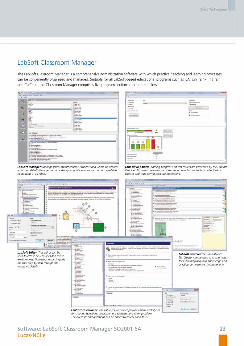
LabSoft Manager: Manage your LabSoft courses, students and whole classrooms with the LabSoft Manager to make the appropriate educational content available to students at all times.
LabSoft Reporter: Learning progress and test results are presented by the LabSoft Reporter. Numerous evaluations of results achieved individually or collectively in courses and tests permit selective monitoring.
LabSoft TestCreator: The LabSoft TestCreator can be used to create tests for examining acquired knowledge and practical competence simultaneously.
LabSoft Editor: This editor can be used to create new courses and revise existing ones. Numerous wizards guide the user step by step through the necessary details.
LabSoft Questioner: The LabSoft Questioner provides many prototypes for creating questions, measurement exercises and exam problems. The exercises and questions can be added to courses and tests.
Software: LabSoft Classroom Manager SO2001-6A Lucas-Nülle
Lucas-Nülle GmbHSiemensstraße 2 · D-50170 Kerpen-Sindorf
Telephone: +49 2273 567-0 · Fax: +49 2273 567-39
www.lucas-nuelle.com
Ref.
no.
: P5
159
Trai
ning
sys
tem
s fo
r po
wer
ele
ctro
nics
–
03/1
3-1G
B (p
rinte
d in
Ger
man
y)
Subj
ect
to t
echn
ical
am
endm
ents
Further information is provided in
our catalogue on drive technology.


![[Electronics] Real-Time Embedded Systems](https://img.pdfslide.us/doc/110x75/6158f43ab303d120476357ae/electronics-real-time-embedded-systems.jpg)