Embed Size (px)
Citation preview
SUMMER INTERNSHIP
TRAINING PROGRAMME
WESTERN DEDICATED FRIEGHT CORRIDOR
MADE BY – Sawan KumarCOLLEGE – MNNIT Allahabad Civil Engg. B.Tech 4th year

ACKNOWLEDGEMENTS
I hereby would like to express my sincerest gratitude to this esteemed organization, which has provided me this precious privilege to pragmatically convert theoretical knowledge into a practically viable experience. During the course of training at L&T WDFC Phase-I, many people have guided me and shared their knowledge with me and I will remain indebted to them throughout my life for making my duration of training a wonderful learning experience.
I would like to thank my mentors without their indelible guidance and support this intern would not have been completed. They took a keen interest in my intern and ensured that my tenure at L&T was the learning experience of the lifetime for me. The exposure to the actual working of the industry that I have got here would not have been possible without their kind support.
Thanks are also due to all the operators of machines and supervisors who took invaluable time off work to amply
satisfy my queries.
OBJECTIVES OF INTERNSHIP
It inspires and helps the students engage in research work, especially at the UG level.
It gives us an opportunity to exchange ideas and suggestions with the members of the faculty
This kind of interaction will help us to build a network of experts, expertise and mentorship of the project
The experience gained from here will guide us in the future career goals.
Strong base for beginning a career in this field.
Western Dedicated Freight Corridor
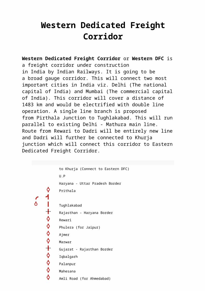
Western Dedicated Freight Corridor or Western DFC is a freight corridor under construction in India by Indian Railways. It is going to be a broad gauge corridor. This will connect two most important cities in India viz. Delhi (The national capital of India) and Mumbai (The commercial capital of India). This corridor will cover a distance of 1483 km and would be electrified with double line operation. A single line branch is proposed from Pirthala Junction to Tughlakabad. This will run parallel to existing Delhi - Mathura main line. Route from Rewari to Dadri will be entirely new line and Dadri will further be connected to Khurja junction which will connect this corridor to Eastern Dedicated Freight Corridor.
to Khurja (Connect to Eastern DFC)
U.P
Haryana - Uttar Pradesh Border
Prithala
Tughlakabad
Rajasthan - Haryana Border
Rewari
Phulera (for Jaipur)
Ajmer
Marwar
Gujarat - Rajasthan Border
Iqbalgarh
Palanpur
Mahesana
Amli Road (for Ahmedabad)
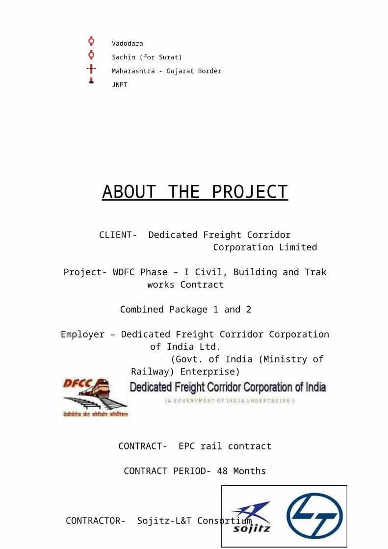
Vadodara
Sachin (for Surat)
Maharashtra - Gujarat Border
JNPT

ABOUT THE PROJECT
CLIENT- Dedicated Freight Corridor Corporation Limited
Project- WDFC Phase – I Civil, Building and Trak works Contract Combined Package 1 and 2
Employer – Dedicated Freight Corridor Corporation of India Ltd. (Govt. of India (Ministry of Railway) Enterprise)
CONTRACT- EPC rail contract
CONTRACT PERIOD- 48 Months
CONTRACTOR- Sojitz-L&T Consortium
Loan Funding- Japan International Cooperation Agency
Length- 626 Km
Date of signing of Contract- 20-08-13
Date of commencement/Notice to Period- 30-08-13
Completion date of Project- 25-08-17
Engineer- N.K.Consortium Nippon Koei Co. Ltd.
Oriental Consultants Co. Ltd. Japan Transportation Consultants Inc.
Nippon Koei India Pvt. Ltd. Oriental Consultants India Pvt. Ltd.
Rites Pvt. Ltd.
MAJOR DETAILS
SCOPE OF WORK- Construction of 626 km of a double track corridor from Rewari in Haryana to Iqbalgarh in Gujarat, via Rajasthan.
The engineering, procurement and construction order secured by the Sojitz-L&T Consortium involves construction of 626 km of a double track corridor from Rewari in Haryana to Iqbalgarh in Gujarat, via Rajasthan, spanning three states. The consortium’s scope includes construction of 1388 track km of railway line, 112 major bridges, 1188 minor bridges, 20 stations along with supply of equipment. The project will be executed using mechanized means of sleepers and track lining machines using the latest technology in railway construction. Adopting advanced construction technologies, the consortium is expected to complete the project in 48 months.
Project Value- Rs 6700 crore
Time left ahead-25% approximately
QUALITY CONTROL LAB
BATCHING PLANT- Concrete plant is a device which combines viscous ingredients to form concrete. Some of the inputs include sand, water, fly-ash, cement.
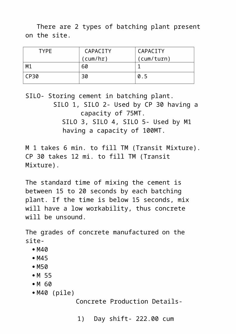
There are 2 types of batching plant present on the site.
TYPE CAPACITY (cum/hr) CAPACITY (cum/turn)
M1 60 1
CP30 30 0.5
SILO- Storing cement in batching plant.SILO 1, SILO 2- Used by CP 30 having a capacity of
75MT.SILO 3, SILO 4, SILO 5- Used by M1 having a capacity of
100MT.
M 1 takes 6 min. to fill TM (Transit Mixture).CP 30 takes 12 mi. to fill TM (Transit Mixture).
The standard time of mixing the cement is between 15 to 20 seconds by each batching plant. If the time is below 15 seconds, mix will have a low workability, thus concrete will be unsound. The grades of concrete manufactured on the site-
M40 M45 M50 M 55 M 60 M40 (pile)
Concrete Production Details-
1)Day shift- 222.00 cum2) Night shift- 224.50 cum
Total- 446.50 cum
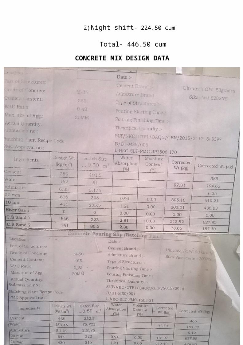
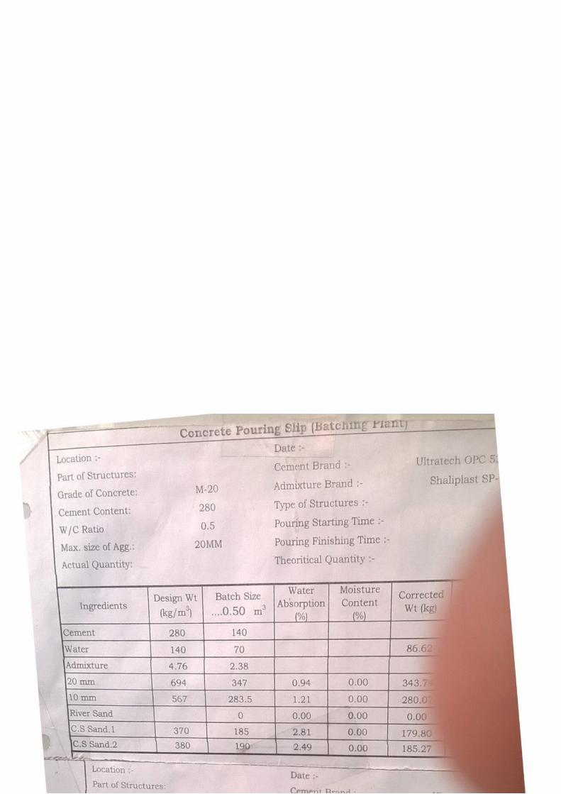
CONCRETE MIX DESIGN DATA
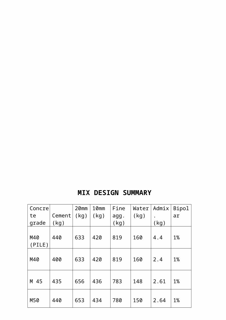
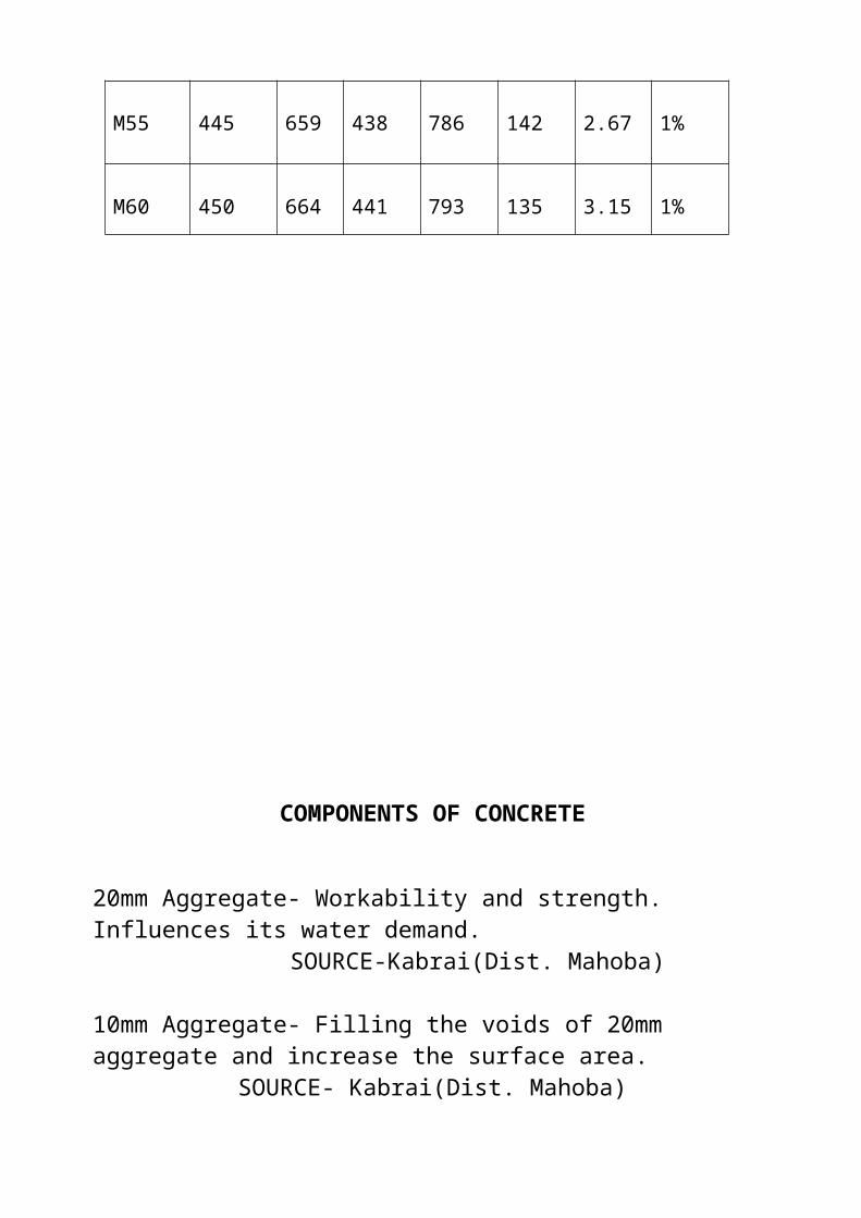
MIX DESIGN SUMMARY
Concrete grade
Cement(kg)
20mm(kg)
10mm(kg)
Fine agg.(kg)
Water(kg)
Admix.(kg)
Bipolar
M40(PILE)
440 633 420 819 160 4.4 1%
M40 400 633 420 819 160 2.4 1%
M 45 435 656 436 783 148 2.61 1%
M50 440 653 434 780 150 2.64 1%
M55 445 659 438 786 142 2.67 1%
M60 450 664 441 793 135 3.15 1%
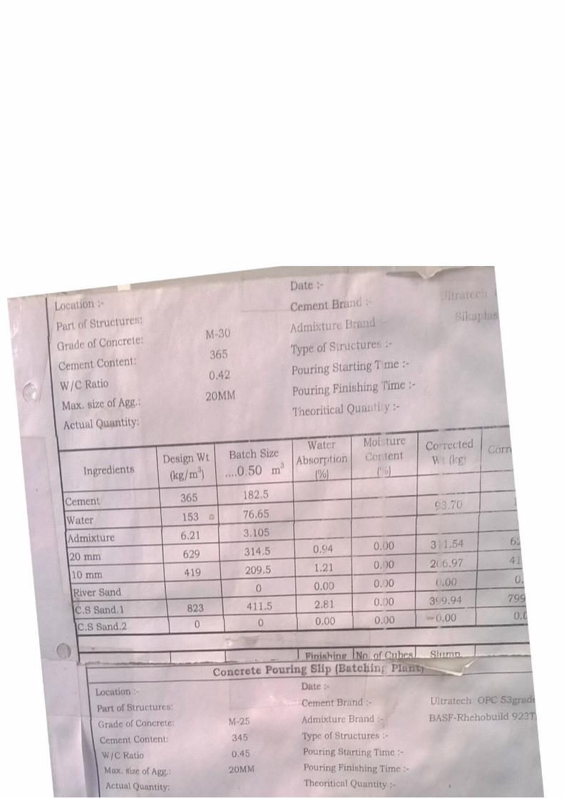
COMPONENTS OF CONCRETE
20mm Aggregate- Workability and strength. Influences its water demand. SOURCE-Kabrai(Dist. Mahoba)
10mm Aggregate- Filling the voids of 20mm aggregate and increase the surface area. SOURCE- Kabrai(Dist. Mahoba)
Fine Aggregate(Sand)- Solidifying of concrete and to fill the voids of 20mm aggregate and 10 mm aggregate.
SOURCE- Hamirpur dist.
Cement- Binding material . GRADE 53 OPCMANUFACTURERS- JK LAKSHMI, ULTRATECH
Water- Preparation of slurry. It eases the transportation. Used for hydration of cement.
Admixture- Retards the IST of cement for 3 hrs. Because of the time it takes for reaching the pouring area. BASF Gelenium.
BIPOLAR Admixture- Anti corrosive.BIPOLAR ATPL
TEST PERFORMED IN THE QUALITY CONTROL LAB
CEMENT-
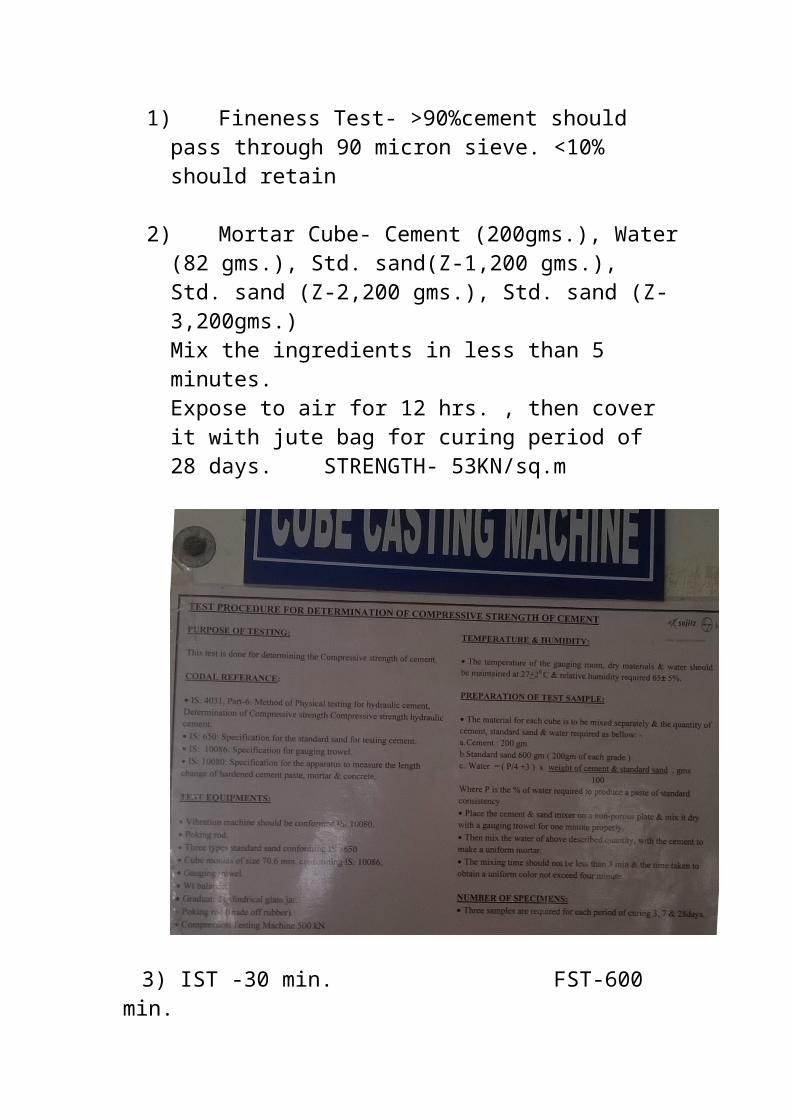
1)Fineness Test- >90%cement should pass through 90 micron sieve. <10% should retain
2)Mortar Cube- Cement (200gms.), Water (82 gms.), Std. sand(Z-1,200 gms.), Std. sand (Z-2,200 gms.), Std. sand (Z-3,200gms.)Mix the ingredients in less than 5 minutes.Expose to air for 12 hrs. , then cover it with jute bag for curing period of 28 days. STRENGTH- 53KN/sq.m
3) IST -30 min. FST-600 min.
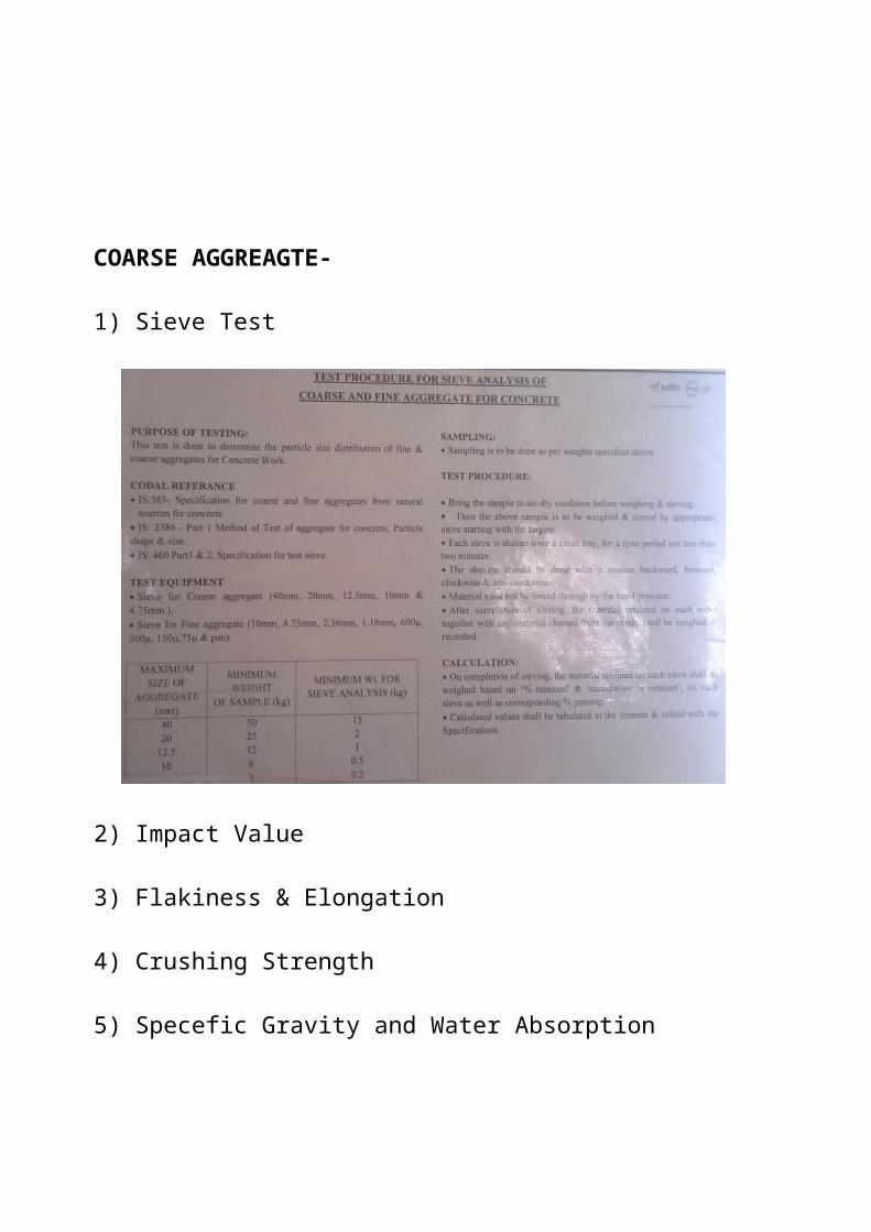
COARSE AGGREAGTE-
1) Sieve Test
2) Impact Value
3) Flakiness & Elongation
4) Crushing Strength
5) Specefic Gravity and Water Absorption
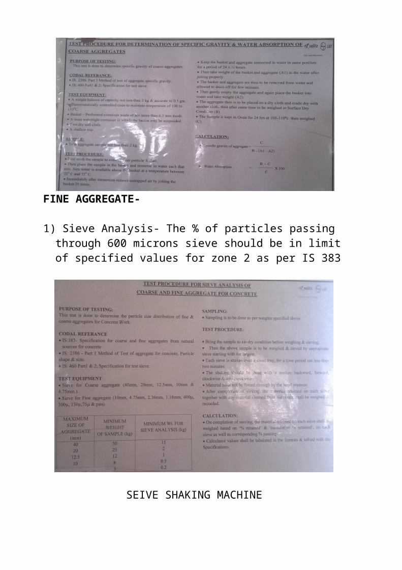
FINE AGGREGATE-
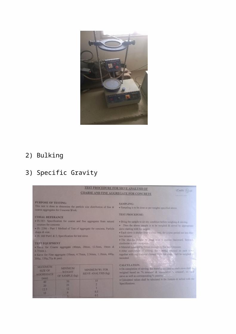
1) Sieve Analysis- The % of particles passing through 600 microns sieve should be in limit of specified values for zone 2 as per IS 383
SEIVE SHAKING MACHINE
2) Bulking
3) Specific Gravity
CONCRETE-
1) Slump Test- Baby misture machine M45-190mm
Height of cone-300 mm Base dia.-200mm Top dia.-100mm
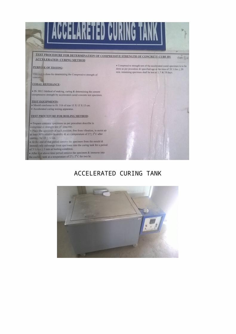
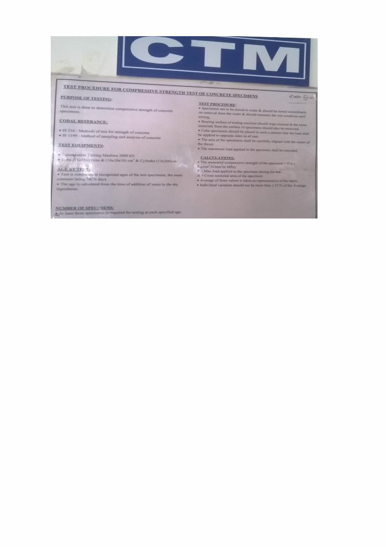
2) Crushing Strength(Through Accelerated curing tank and usually)- IS-456 IS-516
ACCELERATED CURING TANK
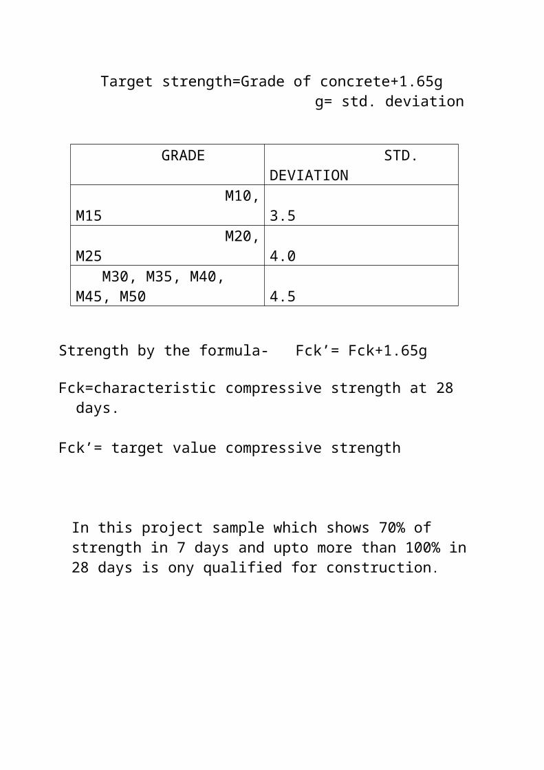
Target strength=Grade of concrete+1.65g g= std. deviation
GRADE STD. DEVIATION M10, M15 3.5 M20, M25 4.0 M30, M35, M40, M45, M50 4.5
Strength by the formula- Fck’= Fck+1.65g
Fck=characteristic compressive strength at 28 days.
Fck’= target value compressive strength
In this project sample which shows 70% of strength in 7 days and upto more than 100% in 28 days is ony qualified for construction.
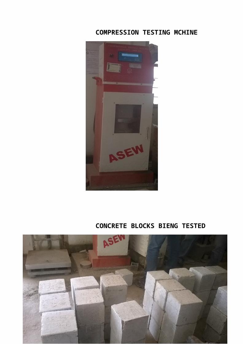
COMPRESSION TESTING MCHINE
CONCRETE BLOCKS BIENG TESTED
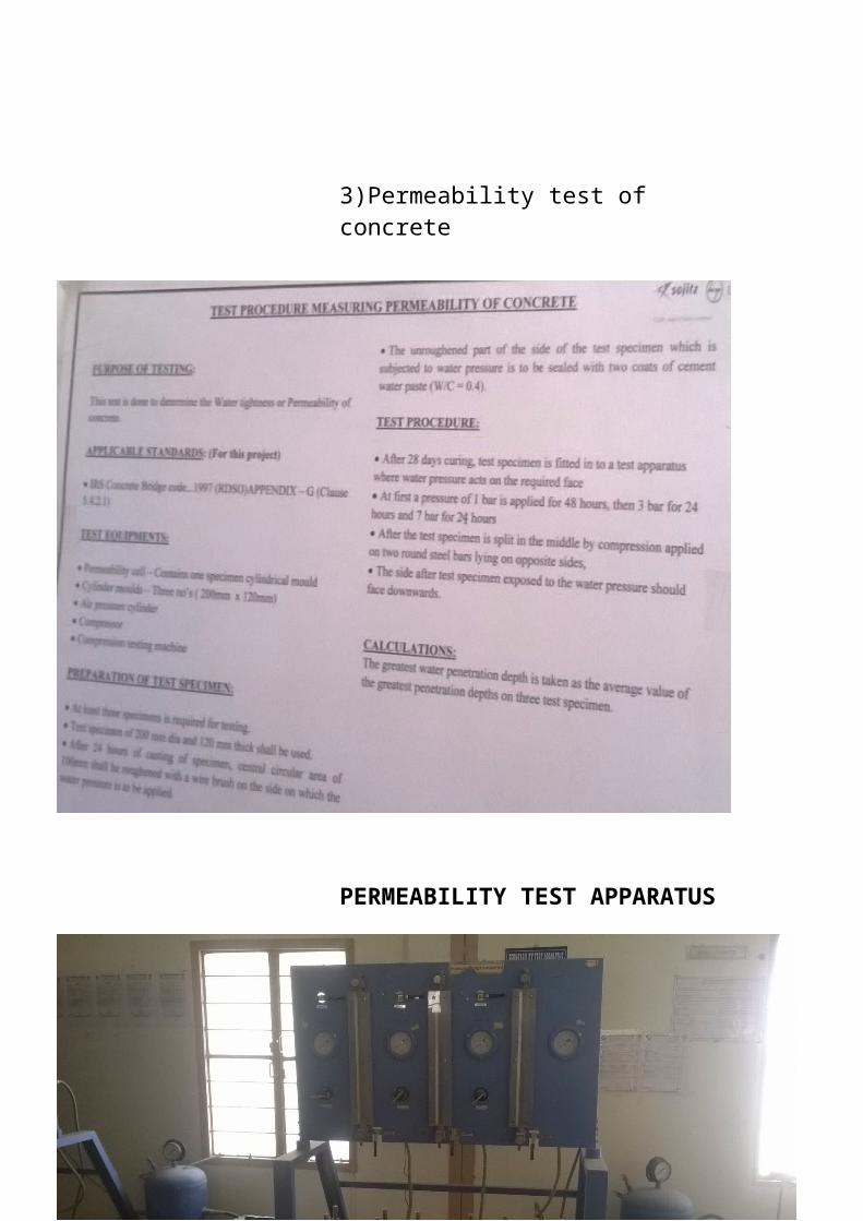
3)Permeability test of concrete
PERMEABILITY TEST APPARATUS
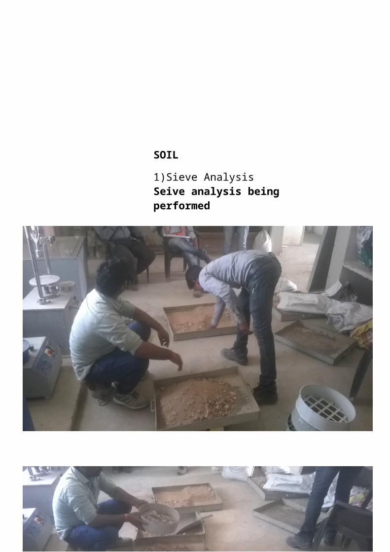
SOIL
1)Sieve AnalysisSeive analysis being performed
2)Proctor compaction test
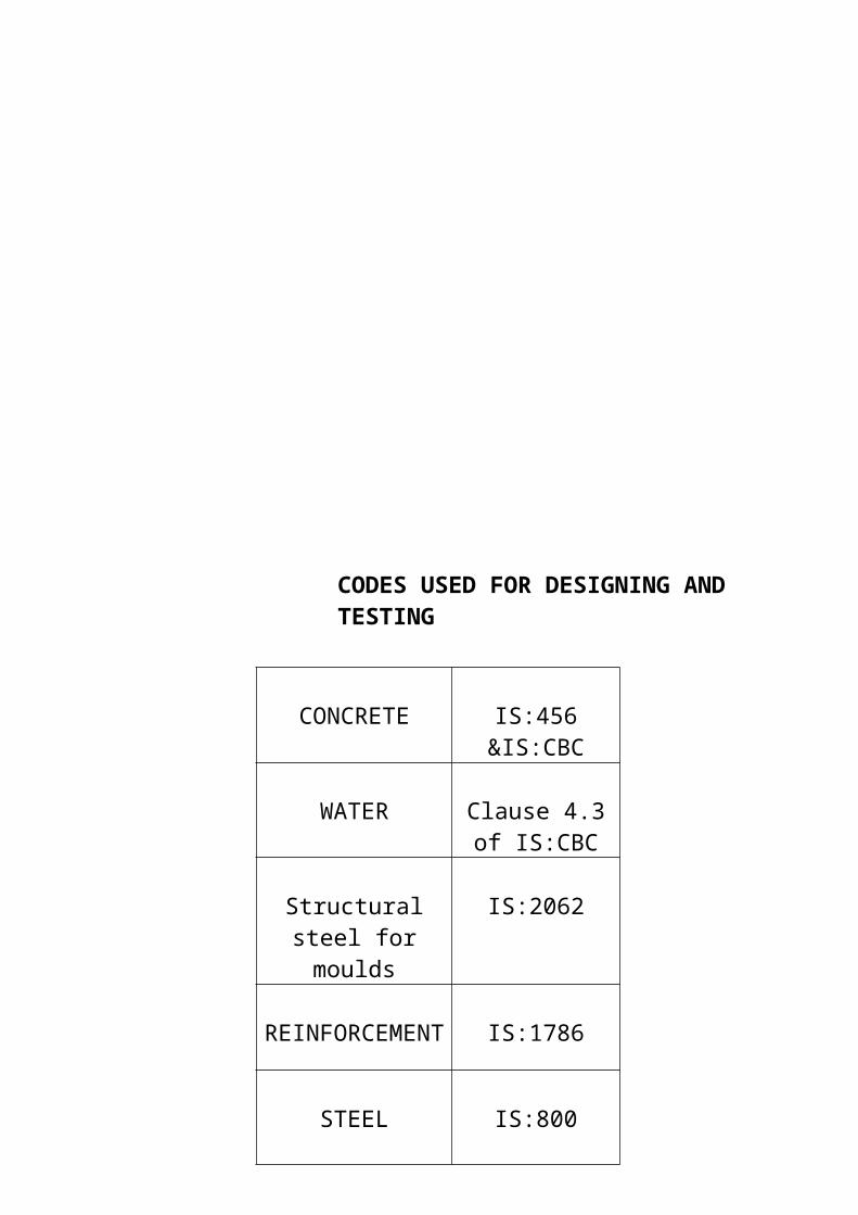
CODES USED FOR DESIGNING AND TESTING
CONCRETE IS:456 &IS:CBC
WATER Clause 4.3 of IS:CBC
Structural steel for moulds
IS:2062
REINFORCEMENT IS:1786
STEEL IS:800
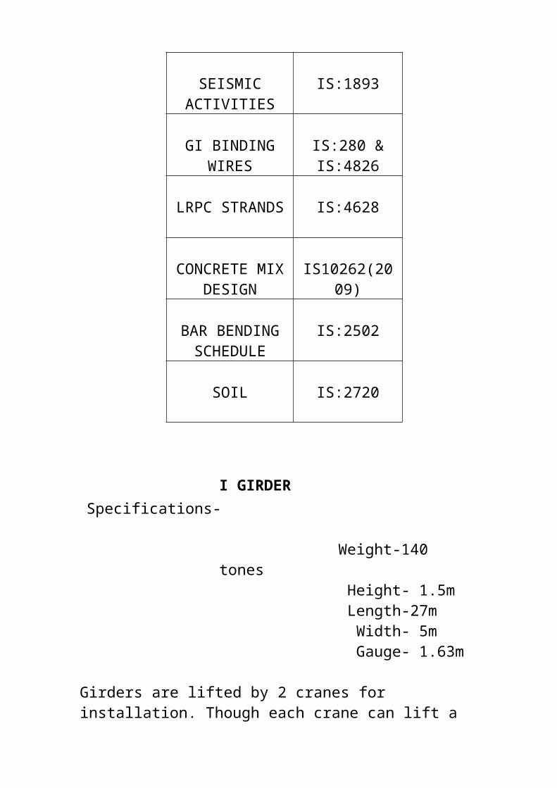
SEISMIC ACTIVITIES
IS:1893
GI BINDING WIRES
IS:280 & IS:4826
LRPC STRANDS IS:4628
CONCRETE MIX DESIGN
IS10262(2009)
BAR BENDING SCHEDULE
IS:2502
SOIL IS:2720
I GIRDERSpecifications-
Weight-140 tones Height- 1.5m Length-27m Width- 5m Gauge- 1.63m
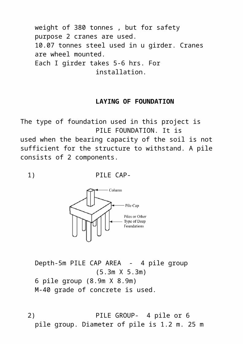
Girders are lifted by 2 cranes for installation. Though each crane can lift a weight of 380 tonnes , but for safety purpose 2 cranes are used.10.07 tonnes steel used in u girder. Cranes are wheel mounted.Each I girder takes 5-6 hrs. For installation.
LAYING OF FOUNDATION
The type of foundation used in this project is PILE FOUNDATION. It is used when the bearing capacity of the soil is not sufficient for the structure to withstand. A pile consists of 2 components.
1)PILE CAP-
Depth-5m PILE CAP AREA - 4 pile group (5.3m X 5.3m)6 pile group (8.9m X 8.9m)M-40 grade of concrete is used.
2)PILE GROUP- 4 pile or 6 pile group. Diameter of pile is 1.2 m. 25 m to 35 m is the length of the pile with efficiency of 80% to 90%. On a simple pier there is 4 pile group, M35 grade of concrete is used.
PROCESS-The site is dig by drilling hydraulic (piling rig) machine
PILING RIG MACHINE
Boring is done with the help of machine and polymer slurry. Advantages of using polymer slurry-
►Controls fluid loss in sands and gravels. Stabilizes excavations
►Highly concentrated. Very small quantities required
►Improves productivity of machines and crews
►Reduces chipping and cleaning of poured concrete
►Reduces or eliminates disposal costs.
►Reduces transport costs and storage space requirements
►Requires less mixing/processing equipment, reducing capital investment, job site congestion, and fuel costs
REINFORCEMENT
Steel reinforcements are used, gene rally, in the form of bars of circular cross section in concrete structure. Plain concrete without steel or any other reinforcement is strong in compression but weak in tension. Steel is one of the best forms of reinforcements, to take care of those stresses and to strengthen concrete to bear all kinds of loads.
They should be closely spaced as per the drawing and properly tied to the main/longitudinal reinforcement.
Reinforcement should be free from loose rust, oil paints, mud etc. it should be cut, bent and fixed properly. The reinforcement shall be placed and maintained in position by providing proper cover blocks, spacers, supporting bars, laps etc. Reinforcements shall be placed and tied such that concrete placement is possible without segregation.
COVER BLOCK-
Cover blocks are placed to prevent the steel rods from touching the shuttering plates and there by providing a minimum cover and fix the reinforcements as per the design drawings. Sometimes it is commonly seen that the cover gets misplaced during the concreting activity. To prevent this, tying of cover with steel bars using thin steel wires called binding wires (projected from cover surface and placed during making or casting of cover blocks) is recommended.
SONIC TESTING OF PILES
Integrity testing is relatively quick and simple and enables number of piles to be examined in a single working day. The method does not identify all imperfections in a pile, but provides information about continuity, defects such as cracks, necking, soil incursions, changes in cross section and approximate pile lengths.

In this test, a small metal / hard rubber hammer is used to produce a light tap on the top of the pile. The shock traveling down the length of the pile is reflected back from the toe of the pile and recorded through a suitable transducer / accelerometer (also held on the top of the pile close to the point of impact) in a computer disk for subsequent analysis.
The primary shock wave which travels down the length of the shaft is reflected from the toe by change in density between the concrete and the sub strata.
However, if the pile has any imperfections or discontinuities within its length these will set up secondary reflections which will be added to the return signal.
CASTING OF GIRDERS IN PCY
Caging is the first step done by labourers . This step takes 2 days. It is done by tying the bars by galvanized iron wire. Caging is not done by welding as it may change the properties of the bar. The caging reinforcement is then lifted by the gantry, and then transferred to bed. The beds on the site are 6 in nos., therefore at a time 6 caging RIF are transferred. Thereby it saves time and labour.
Once the caging reinforcement is transferred to the bed . High tensile wires of steel called ‘tendon’ wires pass through 72 holes of the concrete block with 4 pile group foundation to tighten up the steel wire. The concrete blocks are on both sides of the bed. One end of caging is called fixed end and the other end is called pusher end. This is common for all 6 caging. The tightening of steel wires is done by hydraulic nuts at fixed end and pusher end of the girder. After the stretching of steel wire , concrete is poured over the caging by the machine named as BOOM PLACER. Vibration activity is performed to spread the concrete uniformly.
Curing is performed for 14 days. On the eighth or ninth day when the concrete starts to get stiff, steel wires are cut down before the concrete gains its full strength before curing it.
PRE TENSIONING- Cutting of steel wires before the concrete gains its full strength and to stretch out the tensile wire.
POST TENSIONG-This is done at the site of casting of pier. In this 15 wires are passed through each hole for post tensioning.The process is same as pre tensioning.Hydraulic nuts are used for tightening. The pier cap has 4 ducts .The post tensioning of 1st and 4th duct is done before girder installation and the post tensioning of 2nd and 3rd duct is done after the installation of girders.
There are 2 major differences in pre and post tensioning-
Pre tensioning requires use of both fixed end and pusher end whereas post tensioning does not.
In pre tensioning first steel wire is introduced and then concrete is spread whereas in post tensioning first
concrete is spread and then steel wire is introduced.
PRETENSIONING SYSTEM
BAR BENDING MACHINESThis machine bends bars having dia less than 12mm.