Embed Size (px)
Citation preview

T r a i n i n g M a n u a l
www.vibralign.com 800-379-2250
530 G Southlake Blvd.Richmond, VA 23236
Phone (804) 379-2250Fax (804) 379-0189
©2012 Vibralign, Inc.
Version 1.2

Express Alignment
T r a i n i n g M a n u a l
©2012 Vibralign, Inc.

T a b l e O f C O n T e n T s
Introduction to Alignment ............................................................................................................................1
Chapter 1 Pre-Alignment Considerations ......................................................................................................................3
Chapter 2 Using the XA ...............................................................................................................................................6
Assisted Practice ........................................................................................................................................ 12
Student Practice—Aligning to 1800 rpm Tolerances ................................................................................... 13
Student Practice—Aligning to 3600 rpm Tolerances ...................................................................................14
Chapter 3 What Are Tolerances? ................................................................................................................................ 15
Chapter 4 XA/UPAD Applicaton Settings....................................................................................................................18
Chapter 5 Using the XA in Tripoint Mode ..................................................................................................................24
Chapter 6 Global Settings and File Management ........................................................................................................29
Chapter 7 Student Practice—Checking for Softfoot Using the XA ..............................................................................35
Chapter 8 Student Practice—Using Thermal Targets ...................................................................................................38
Chapter 9 Student Practice—Solving Base-bound/Bolt-bound Problems ..................................................................... 41
Chapter 10 Student Practice—Using the XA in Clock Mode .........................................................................................43
Vertical Alignment Demonstration .............................................................................................................48
Appendix .............................................................................................................................................................................................51


i n T r O d u C T i O n T O a l i g n M e n T
Alignment BAsics
the machines we align:
Basic
The most basic machines to align consist of a driver and driven element. The driven unit is usually considered to be stationary and the driver movable. The movable unit is repositioned in relation to the stationary unit.
machine trains
Sometimes a machine train will include a driver, and more than one driven element. When aligning a machine train, there is more than one alignment to be made.
Typical Drivers: Electric Motor, Steam Turbine, Gas Turbine, Engine, Wind Turbine, Hydraulic Motor
Typical Driven Elements: Pump, Fan, Generator
Intermediate Devices: Gearbox, Clutch, Fluid Coupling
Rotational axes
All shafts, straight or bent, rotate on an axis which forms a straight line.
shaft Alignment Defined
Shaft alignment is the act of measuring the relative position of two machines that are coupled and repositioning them so that the rotational axes of the two shafts form a straight line (collinear) when the machines are at normal operating temperatures.
types of misalignment
Offset misalignment
Offset Misalignment is the actual radial position of the movable rotational center relative to the stationary center. If the shafts are not parallel, the offset misalignment is different at every axial position.
Offset misalignment is expressed in mils.
� 0.001" = 1 mil
Offset misalignment Vs Dial Readings
If a dial indicator measuring on the rim is set to zero and then rotated 180 degrees the dial reading (TIR) will be 2X the offset misalignment.
� Offset misalignment = ½ TIR
Angular misalignment
Angular Misalignment is the slope relationship of the two shafts. The slope has a positive value if the offset values are more positive at the rear feet than at the coupling.
Angular misalignment is expressed in mils per inch.
Stationary Movable
1

i n T r O d u C T i O n T O a l i g n M e n T
Angular misalignment Vs gap Difference
If you use calipers, inside micrometers, or a dial indicator to measure face to face misalignment, the result you get is the gap difference top to bottom or side to side in mils. Angles cannot be expressed as a distance alone. Divide the gap difference by the diameter at which you measure the gap to express the gap difference as angular misalignment.
Gap difference/diameter = angular misalignment
tOleRAnces
Angular Misalignment Offset Misalignment
Mils per inch Mils.001/1" .001"
RPM Excellent Acceptable Excellent Acceptable
3600 0.3/1" 0.5/1" 1.0 2.0
1800 0.5/1" 0.7/1" 2.0 4.0
1200 0.7/1" 1.0/1" 3.0 6.0
900 1.0/1" 1.5/1" 4.0 8.0
misAlignment FORcesMisalignment creates forces at the coupling which are exerted on the shafts. This results in reduced bearing and seal life.
The force effects of misalignment can be simplified by considering the misalignment as a simple lever. Misalignment at the coupling creates a moment of force acting on an effort arm. This will create a first class or second class lever with either the inboard or outboard bearing acting as a fulcrum. The length of the motor shaft between its bearings is the resistance arm. The objective of shaft alignment is to minimize coupling forces by making two rotational axes form a single line while the machine operates.
About making precise alignments:
Fast and accurate alignment should be simple. In fact, most alignments can be accomplished in one or two corrective moves.
� It is helpful to understand some alignment basics.
� Pre-alignment steps are mandatory.
� You must know when you are finished.
� Rigid couplings present unique challenges and final alignment must be near perfect.
� Alignment data can be obtained with the couplings assembled or disassembled.
� When it is humanly possible, both shafts should be rotated when obtaining alignment data
2

C h a p T e r 1
Pre-Alignment Considerations
3

Pre-alignment checks and corrections are performed to either
improve machinery reliability or to facilitate the alignment
process. In either case, pre-alignment is a very important
phase of the alignment process.
The pre-alignment process could include all of the following
checks: (1) Clean up around and under machinery feet. (2)
Consolidation of small shims with fewer thicker pieces. (3)
Checking run out. (4) Checking pipe strain. (5) Performing a
lift check to check bearing clearances. (6) Rough alignment. (7)
Checking hub separation on spacer couplings. (8) Recording
and tightening bolts in a known sequence. (9) Checking final
soft foot.
We will limit the scope of this chapter to what we term “the pre-
alignment essentials.” You will demonstrate understanding of
the following terms and procedures: rough alignment, correct
obvious soft foot, tightening bolts in a known sequence, and
correcting final soft foot.
ROugh Alignment
Rough alignment is performed to expedite the precision
alignment process. It is intended to quickly get the machines
“in the ball park.” On close-coupled machines (those with no
spacer coupling), rough alignment can be performed with a
scale or any straight edge to remove vertical and horizontal
offset misalignment. On machines with spacer couplings,
we recommend that you correct both the angular and offset
misalignment vertically and then the angular and offset
misalignment horizontally.
Using a scale or straight edge, correct rough vertical
misalignment by referencing the highest hub. Place scale
firmly on the highest hub and raise or lower the movable shaft
to within 20 mils (0.020") of the stationary hub.
Using a scale or straight edge, correct rough horizontal
misalignment by referencing the hub closest to you. Place
scale firmly on the hub and adjust the movable shaft to within
20 mils (0.020") of the stationary hub.
OBViOus sOFt FOOt
Soft foot occurs when the machine feet do not rest flatly on
the machine base. Soft foot is caused by deformed machine
base plates or by deformed machine feet. In either case, the
effect when tightening the bolts is that the bearings become
misaligned, bearing clearances change and the machine
p r e - a l i g n M e n T C O n s i d e r a T i O n s
4

C h a p T e r 1
rotational center is moved. Machinery performance is adversely
affected by a soft foot’s effect on bearings. Precision alignment
is nearly impossible to perform unless soft foot is corrected.
Correcting gross soft foot can be accomplished by loosening
all the mounting bolts and finding any obviously loose shim
packs. Add shims as needed to make a snug fit.
tightening sequence
You will find that specifying, recording and maintaining a
tightening sequence will result in a better and quicker alignment.
The fact is that the machine will move (both vertically and
horizontally) as we tighten down the bolts. This is true even
after we correct soft foot. If you follow a known sequence you
will minimize and make this movement predictable during the
alignment process.
Often when making vertical corrections, people will only
loosen two bolts at a time to try to hold horizontal position.
This practice is acceptable, but some horizontal movement
will likely occur anyway. Therefore, you should re-loosen all
bolts and retighten in the recorded sequence after all vertical
adjustments are complete.
In practice, make at least three passes around the bolts: Snug
on the first pass, ~50% on the second pass and completely
tight the third pass. Follow the same sequence throughout
the alignment.
FinAl sOFt FOOt
Soft foot issues account for most alignment repeatability
issues. For that reason, we address it twice. Now that the
obvious soft foot issues are resolved and all feet are tight,
we’ll make one final check on soft foot. Loosen one bolt at
a time and check with a 2 mil (0.002") shim or feeler gage
at that foot. Correct any foot with 2 mils or more softness.
Re-tighten the bolt and proceed to the next foot.
If the foot has an angular relationship to the base, you can
correct this by cutting a partial shim to make up the angular
correction. When cutting partial shims from pre-cut stock,
always leave the shim “tab” intact. The tab can be used to
make each shim pile organized and the partial shim will return
to the original position. Never “feather” or step shims out
to fix an angled foot. It is unlikely the angular correction will
be duplicated when the shim piles are changed during the
alignment.
5

chApteR twO gOAlsAt the conclusion of this chapter you will see how to:
� Perform all prealignment steps
� Setup XA sensors correctly
� Enter dimensions correctly
� Select tolerances for 1800 rpm
� Measure misalignment
� Correct vertical and horizontal misalignment with Verti-Zontal compound move
� Remeasure
� Make corrections if necessary and remeasure
� Save results
� Unmount and stow sensors in storage case
C h a p T e r 2
Using the XA
6

1. set up the XA1.1 Turn on the XA to allow it to boot up.
1.2 Mount the ‘S’ sensor on the stationary shaft.
� The sensors may be mounted on the shafts or on the coupling hubs.
� Place the bracket on the shaft and pull the chain under the shaft and hook it over the pin.
� Hand tighten the nut.
1.3 Turn on ‘S’ sensor by pressing the power button on the Bluetooth module.
1.4 Mount the ‘M’ sensor on the movable shaft in the same plane as the stationary sensor.
� Place the bracket on the shaft and pull the chain under the shaft and hook it over the pin.
� Hand tighten the nut.
1.5 Turn on ‘M’ sensor by pressing the power button on the Bluetooth module
1.6 From the main menu, touch the horizontal alignment icon.
1.7 You will be prompted to select the speed of the equipment that you are aligning. Press OK to return to the alignment screen.
� The lasers on the sensors will turn on and the graphic on screen will show the orientation of the sensors.
1.8 Aim the lasers
� Loosen the green clips to slide the sensors up and down.
� The sensors will be on different elevations.
� Adjust so the line laser falls within the middle of the sensor. The entire length of the detector is acceptable for measuring misalignment.
u s i n g T h e f i X T u r l a s e r X a
7
� Inclinometer values (the angular position of each sensor) are displayed over each sensor to aid in the aiming process
� The screen will show green lights over each sensor when each laser is on the detector.
1.9 Using the wrench, tighten the nuts another half turn to ensure the brackets will not rock on the shaft.
2. enteR DimensiOns2.1 Touch the “?” to input the dimension from the
keypad.
2.2
The first dimension to enter is the distance from the S to the M sensor. Measure from center of post to center of post.
2.3 Measure and enter the correct dimension. Press OK.
� All measurements are to the closest 1⁄8".
2.4 The next dimension is from the center of the coupling to the center of the movable sensor. If the dimension in the display is not correct (one sensor is closer to the center of the coupling), measure and enter the correct dimension. Press OK.
2.5 Measure from the center of the movable sensor post to center of the front movable foot. Enter the dimension on the keypad and press OK.
2.6 Measure and enter the dimension from the front movable foot to the rear movable foot and press OK.
3. meAsuRe misAlignment3.1 Viewing the machine from the movable to the
stationary, rotate the sensors to the 9:00 position. The starting measurement is registered by pressing the measurement button flashing on the screen.
u s i n g T h e f i X T u r l a s e r X a
8

3.2 The sensors are then rotated outside of the red shaded portion of the circle to the 12:00 position.
3.3 When the sensors are steady for two seconds, the second reading will be acquired.
3.4 Again, the sensors are rotated outside of the red shaded portion of the circle. When the sensors are steady for two seconds, the third and final reading at 3:00 will be acquired.
4. Alignment Results � Both the vertical and horizontal alignment results are displayed.
� Green coupling icons represent values that are within tolerance.
� Orange values are within twice the tolerance.
� Red values are more than double the tolerance values.
� Only the angle and offset values determine the alignment condition.
� Displayed foot values are for making necessary corrections.
� If all values are acceptable, a green check mark will appear above the coupling icon. Skip to Section 8-Document.
� An orange circle or red exclamation point will be displayed if any value is unacceptable. Proceed with next step.
5. the VeRti-zOntAl cOmpOunD mOVe: cORRecting VeRticAl misAlignment5.1 Press shim icon in bottom right-hand corner.
5.2 Loosen all bolts holding down the movable element.
5.3 Follow instructions on screen for removing or inserting shims.
C h a p T e r 2
9
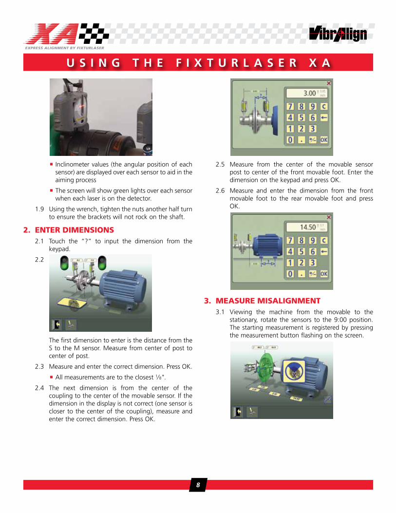
5.4 Do not retighten hold down bolts yet.
6. cORRecting hORizOntAl misAlignment6.1 The horizontal corrections are done with live
readings. Press icon in bottom right-hand corner.
6.2 Values are live in the direction the sensors are pointing. Ensure the sensors are at 3:00 or 9:00.
6.3 Positive values: the machine is away from you; adjust it toward you in the direction of the arrow. Negative values: the machine is toward you; adjust it away from you. Start with the largest number first.
6.4 Adjust the movable machine until the angle and offset are within tolerances.
6.5 Tighten feet using sequence established in the pre-alignment steps. The Verti-Zontal compound move is complete.
7. Re-meAsuRe7.1 To re-measure, press the re-measure button. Press
the re-measure button again on the confirmation pop-up.
7.2 Follow the steps from Section 3 above to complete the measurement process.
7.3 Verify the results are within tolerance.
u s i n g T h e f i X T u r l a s e r X a
10

8. DOcument8.1 After re-measuring, press the file save icon.
8.2 Tap in the white file name area.
8.3 Enter the name from the keyboard. Press OK
8.4 Press OK again to save file in My Measurements
C h a p T e r 2
11

pRActice gOAlsAt the conclusion of this practice, with a little help, you will be able to:
� Perform all prealignment steps
� Setup XA sensors correctly
� Select tolerances for 1800 rpm
� Enter dimensions correctly
� Measure misalignment
� Correct vertical and horizontal misalignment with Verti-Zontal compound move
� Remeasure
� Make corrections if necessary and remeasure
� Save results
� Unmount and stow sensors back in storage case
p r a C T i C e
Assisted Practice
12

pRActice gOAlsAt the conclusion of this practice, on your own, you will be able to:
� Perform all prealignment steps
� Setup XA sensors correctly
� Select tolerances for 1800 rpm
� Enter dimensions correctly
� Measure misalignment
� Correct vertical and horizontal misalignment with Verti-Zontal compound move
� Remeasure
� Make corrections if necessary and remeasure
� Save results
� Unmount and stow sensors back in storage case
p r a C T i C e
Student PracticeAligning to 1800 rpm Tolerances
13

pRActice gOAlsAt the conclusion of this practice you will be able to:
� Perform all prealignment steps
� Setup XA sensors correctly
� Select tolerances for 3600 rpm
� Enter dimensions correctly
� Measure misalignment
� Correct vertical and horizontal misalignment with Verti-Zontal compound move
� Remeasure
� Make corrections if necessary and remeasure
� Save results
p r a C T i C e
Student PracticeAligning to 3600 rpm Tolerances
14

chApteR thRee gOAlsAt the conclusion of this chapter, you will understand the:
� Difference between targets and tolerances
� Relationship of speed to tolerances
� ‘Zone of Good Alignment’
� Repeatability
C h a p T e r 3
What Are Tolerances?
15

tOleRAncesTolerances are the allowable deviations from the target values. So far our goal has been to make the movable shaft colinear with the stationary shaft. We have had a target of zero offset with zero angularity between the shafts. The allowable offset deviation from zero, or tolerance, for 1800 rpm is from positive four mils to negative four mils, or 0±4 mils. That allows an eight mil window around our target. The angularity portion is treated similarly—0±0.7 mils/in.
It is very unlikely that perfect alignment is achievable—or is really that important. The objective of shaft alignment is to minimize radial forces by minimizing the offset at the coupling where power is transmitted. We minimize axial forces by minimizing the slope relationship of the two shafts. The coupling tolerances we recommend are based on widely accepted angle and offset values. You can choose to be more or less permissive. The XA allows us to input up to three of our own tolerances if the values in the table do not fit our particular job.
You can see from the table below that as the speed increases, the tolerances become tighter. This is because as the speed increases, so do the forces generated by misalignment. It’s these forces that decrease the life of couplings, seals, bearings, etc.
Angular Misalignment Offset Misalignment
Mils per inch Mils.001/1" .001"
RPM Excellent Acceptable Excellent Acceptable
3600 0.3/1" 0.5/1" 1.0 2.0
1800 0.5/1" 0.7/1" 2.0 4.0
1200 0.7/1" 1.0/1" 3.0 6.0
900 1.0/1" 1.5/1" 4.0 8.0
zOne OF gOOD Alignment
The graph below shows a zone of acceptance for a 3600 rpm machine using angular and offset tolerances. When the movable shaft axis falls completely within the shaded ‘bowtie,’ acceptable alignment is achieved. There is a large range of foot values that are acceptable.
The plotted line represents a shaft with offset misalignment of 1.0 mil (0.001") at the coupling center. The slope is 0.1 mil/1". This is a very good alignment!
A few important things to remember about working within the tolerances:
� Keep the back foot value larger than the front foot
� Keep the sign of both values the same
W h a T a r e T O l e r a n C e s ?
16

C h a p T e r 3
RepeAtABilityTrying to troubleshoot readings that have you moving in one direction then another? Are you adding shims in one move and removing them the next? Are you wondering if you’ll ever get consistent, repeatable results?
As we have illustrated in earlier chapters, the quality of the alignment can only be judged by the results at the coupling center where the shaft centerlines of rotation intersect. Only the angularity and offset results are compared between sets of readings. We should expect our angularity measurement to vary no more than ±0.1 mils/inch. Our offset measurement should vary no more than ±1.0 mils. Foot values should not be used as an indicator of repeatability. The amount of variation that can occur in the foot values is directly dependent upon the distance between the movable feet.
If you have determined that the angularity and/or offset values are not consistent enough to meet your needs, there are generally two areas of measurement error: either the alignment data is not collected in a consistent fashion (loose bracket?) or the machine you are measuring is not behaving in a consistent fashion (softfoot?). Either way, we need to find the problem and fix it.
Let’s look at a few examples.
problems while taking data:
� Loose chain brackets
� Loose extension rod on chain/magnetic bracket
� Sensors mounted to something loose (hub loose on shaft? Mounted on coupling element cover instead of solid part of coupling?)
� Sensor brackets deflecting while turning (rubbing bearing housing, hitting a bolt, etc.)
� Background vibration (through piping, bases/foundations)
� Wrong dimensions entered
problems with machines being aligned:
� Softfoot
� Loose hold down bolts on movable
� Loose hold down bolts on stationary
� Looseness in coupling
� Shaft deflection while turning
� Coupling too rigid
� Temperature changes
� Looseness/rubs in bearings
� Inadequate base (thin, cracked grout, etc.)
� Cupped washers
� Bolts/tapped threads not true
� Crowned/cupped bases affecting horizontal/vertical moves
17

C h a p T e r 4
XA/UPAD Applicaton Settings
chApteR FOuR gOAlsAt the conclusion of this chapter you will be able to:
� The different program settings within the alignment tools
� Different operating modes for the XA-D and UPAD
� Charging and battery care for the XA-D and UPAD
18
X a / u p a d a p p l i C a T O n s e T T i n g s
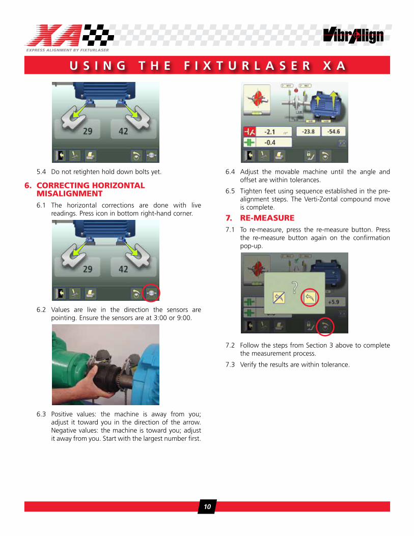
meAsuRement units AnD ResOlutiOn
Opens window for selection of measurement unit and resolution. Selecting the mm/inch sets the default units for the alignment. The buttons below select the resolution of the results shown on the screen. We recommend using the highest resolution (0.01mm or 0.1 mils) to allow for monitoring the results easier.
unit OF AngulARity
Opens window for activating or disabling coupling gap. With the coupling gap activated, the angularity is expressed as the total gap at the coupling diameter. The coupling diameter is entered from the results screen. With the coupling gap disabled, angularity is expressed as coupling gap per unit length of diameter (mils/in).
meAsuRement methOD
Opens selection window for measurement method. Available options are Tripoint, Express, and Clock. Further discussion on the measurement methods is found in the student practices.
sAmpling time
Opens window for selection of sampling time. The sampling time adjusts how long each measurement takes while collecting the data. In higher vibration areas, a longer sampling time may be entered to average more data. Three seconds is acceptable for most applications.
cOupling type selectOR
Allows user to select between short, flexible coupling element, or long, spacer type coupling.
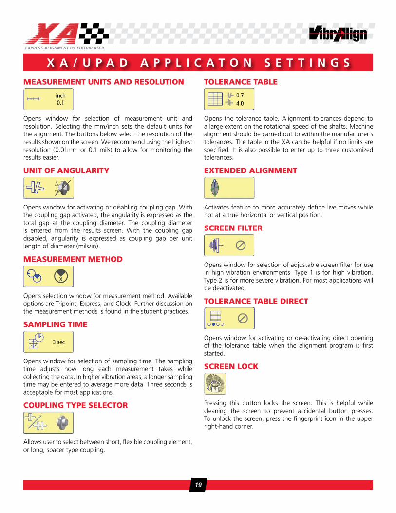
tOleRAnce tABle
Opens the tolerance table. Alignment tolerances depend to a large extent on the rotational speed of the shafts. Machine alignment should be carried out to within the manufacturer’s tolerances. The table in the XA can be helpful if no limits are specified. It is also possible to enter up to three customized tolerances.
eXtenDeD Alignment
Activates feature to more accurately define live moves while not at a true horizontal or vertical position.
scReen FilteR
Opens window for selection of adjustable screen filter for use in high vibration environments. Type 1 is for high vibration. Type 2 is for more severe vibration. For most applications will be deactivated.
tOleRAnce tABle DiRect
Opens window for activating or de-activating direct opening of the tolerance table when the alignment program is first started.
scReen lOck
Pressing this button locks the screen. This is helpful while cleaning the screen to prevent accidental button presses. To unlock the screen, press the fingerprint icon in the upper right-hand corner.
19

Resume FunctiOn
Pressing this button stores all system and alignment data to allow the unit to be put in Sleep mode. When turning the unit back on, press the resume button to pick up where you left off.
mAchine DeFineD DAtA � Opens windows for adding a new machine to the Machine Defined Data function.
� Entered data such as dimensions, thermal offsets, and tolerances will be saved for easy retrieval.
pOweR mAnAgement upAD
Operating modes
The UPAD has three operating modes: On, Sleep, and Transportation.
� The LED status light on the UPAD indicates the Operating mode: Flashing green indicates ON mode; flashing green with solid orange indicates on and charging; and, no light indicates Sleep mode.
� The single black button on the UPAD turns on the display unit from either Sleep or Transportation mode by a short press and release of the button.
� Note: The single black button is not used to turn off the UPAD; however, it can be used to enter Sleep mode by a short press and release.
� The UPAD is put into Transportation mode (OFF) by a switch on the back of the unit.
On mode
On mode, Normal Function = Status LED is flashing green, screen is illuminated, battery switch is on.
� When the UPAD is started up from Transportation mode (Off) the display screen will first show a start up image, the screen will then go black until the start screen is displayed. This is normal and will take 20 to 30 seconds. The status LED will be flashing green immediately.
On mode w/Screen Saver activated = Status LED is flashing green, screen is blank, battery switch is on.
� The Screen Saver is a power saving function which turns off the backlight. Touch the screen to reactivate backlight for normal function.
� The Screen Saver Function is factory set to turn off the backlight when the display screen has not been touched for 5 minutes. This setting cannot be changed; however, it can be deactivated in the Power Setting in Global Settings.
sleep mode
Sleep mode activated = Status LED is off, screen is blank, battery switch is on.
� Sleep mode is a power saving function which stores the current state of the UPAD in memory so when the display is turned back on, normal function will resume at the same place. If the UPAD is left in Sleep mode it will continue to consume a small amount of power.
� To exit Sleep mode and resume normal function, press and release the black button.
� Sleep mode is a user-defined function that activates when the display screen has not been touched after a predetermined amount of time. The Sleep mode (Auto-off) time can be set (up to 99 min.) or deactivated in Global Settings. The factory default setting is 15 minutes.
� Sleep mode can be entered by pressing the black button or red icon on the main menu.
transportation mode
Transportation mode completely disconnects the batteries of the UPAD and should be used when transporting the Fixturlaser UPAD by air or for long term storage.
� The UPAD is placed into Transport mode by first placing the unit into Sleep mode then sliding the battery switch on the underside to the disconnect position.
� To turn on the UPAD from Transport mode, first slide the battery switch on the underside to the connect position then press and release the black button. The UPAD will then
X a / u p a d a p p l i C a T O n s e T T i n g s
20

start up as described in On mode.
power supply
The UPAD display is powered by a high-capacity rechargeable Li-polymer battery or by the external USB charger.
� The operating time for fully charged batteries is approximately 10-15 hours with typical use. The battery level is indicated by the battery icon on the main menu.
� The status light on the UPAD is continuous orange when the external USB charger is plugged in and the battery is charging.
� The approximate charge time for fully drained batteries is 6 hours, longer if the UPAD is turned on while charging.
� In order for the battery charging to begin the UPAD must be turned ON; charging will not start otherwise. Once charging has begun, as indicated by the orange status light, the UPAD can then be put into Sleep mode to complete the charging cycle.
� To achieve a full charge the UPAD must be put into Sleep mode after the charge cycle has begun; otherwise, the battery will only charge to 80% of capacity.
� When the battery level is low, a low battery warning will pop up on the UPAD display screen.
� If the UPAD turns off due to a low battery level, the current state of the UPAD will be stored and can be resumed at the same place when turning the unit back on (after plugging
in the external USB charger) by selecting the resume button when prompted.
NOTE: If the battery has been completely drained for some time the UPAD needs to be charged for at least 15 minutes to receive an initial charge before the unit will start.
� The battery contains safety circuitry that is monitored by the UPAD and therefore should only be replaced by VibrAlign.
pOweR mAnAgement XA-D
Operating modes
The XA-D has three operating modes: On, Sleep, and Off.
The top right LED status light on the XA-D Display Unit indicates the operating mode: solid green indicates On mode, flashing green indicates Sleep mode, and no light indicates Off mode.
The single red button on the XA-D turns on the display unit from Off or Sleep mode by a short press and release of the button. DO NOT HOLD the RED BUTTON DOWN!
If the XA-D has unintentionally been turned Off or put into Sleep mode and needs to be turned on again, wait 10-15 seconds for the shut down process to finish before pushing the red button to turn it back on.
The single red button is not used to turn off the XA-D; however, it can be used to enter Sleep mode by a short press and release.
On mode
On mode, normal function = Display status LED is solid green, display screen is illuminated.
� When turning on the XA-D from Off mode, the display screen will take up to a minute to illuminate. The status LED will turn solid green immediately.
On mode, Screen Saver activated = Display status LED is solid green, display screen is blank.
� The Screen Saver is a power saving function which turns off the backlight. Touch the screen to reactivate backlight for normal function.
� The Screen Saver function is factory set to turn off the backlight when the display screen has not been touched for 5 minutes. This setting cannot be changed; however, it can be deactivated in the Power Setting in Global Tools.
sleep mode
Sleep Mode activated = Display status LED is flashing green,
C h a p T e r 4
21
display screen is blank.
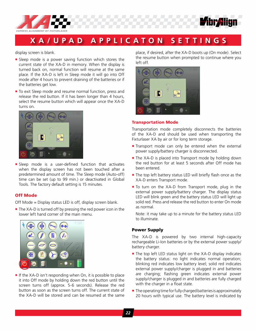
� Sleep mode is a power saving function which stores the current state of the XA-D in memory. When the display is turned back on, normal function will resume at the same place. If the XA-D is left in Sleep mode it will go into Off mode after 4 hours to prevent draining of the batteries or if the batteries get low.
� To exit Sleep mode and resume normal function, press and release the red button. If it has been longer than 4 hours, select the resume button which will appear once the XA-D turns on.
� Sleep mode is a user-defined function that activates when the display screen has not been touched after a predetermined amount of time. The Sleep mode (Auto-off) time can be set (up to 99 min.) or deactivated in Global Tools. The factory default setting is 15 minutes.
Off mode
Off Mode = Display status LED is off, display screen blank.
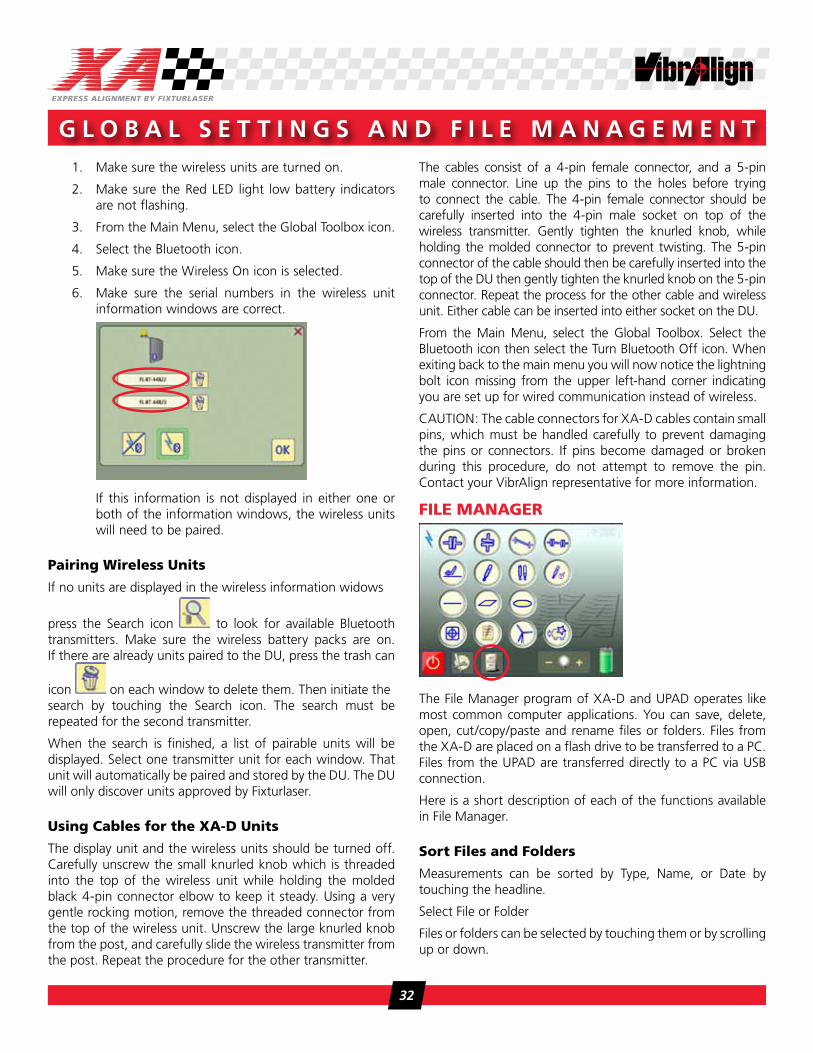
� The XA-D is turned off by pressing the red power icon in the lower left hand corner of the main menu.
� If the XA-D isn’t responding when On, it is possible to place it into Off mode by holding down the red button until the screen turns off (approx. 5-6 seconds). Release the red button as soon as the screen turns off. The current state of the XA-D will be stored and can be resumed at the same
place, if desired, after the XA-D boots up (On mode). Select the resume button when prompted to continue where you left off.
transportation mode
Transportation mode completely disconnects the batteries of the XA-D and should be used when transporting the Fixturlaser XA by air or for long term storage.
� Transport mode can only be entered when the external power supply/battery charger is disconnected.
� The XA-D is placed into Transport mode by holding down the red button for at least 5 seconds after Off mode has been entered.
� The top left battery status LED will briefly flash once as the XA-D enters Transport mode.
� To turn on the XA-D from Transport mode, plug in the external power supply/battery charger. The display status LED will blink green and the battery status LED will light up solid red. Press and release the red button to enter On mode as normal.
Note: it may take up to a minute for the battery status LED to illuminate.
power supply
The XA-D is powered by two internal high-capacity rechargeable Li-Ion batteries or by the external power supply/battery charger.
� The top left LED status light on the XA-D display indicates the battery status: no light indicates normal operation; blinking red indicates low battery level; solid red indicates external power supply/charger is plugged in and batteries are charging; flashing green indicates external power supply/charger is plugged in and batteries are fully charged with the charger in a float state.
� The operating time for fully charged batteries is approximately 20 hours with typical use. The battery level is indicated by
X a / u p a d a p p l i C a T O n s e T T i n g s
22

the battery icon on the main menu.
� The charge time for fully drained batteries is approximately seven hours—longer if the XA-D is turned on while charging.
� If the XA-D turns off due to a low battery level, the current state of the XA-D will be stored and can be resumed at the same place when turning the unit back on. After plugging in the external power supply/charger, select the resume button when prompted.
� When the battery level is low a low battery warning will pop up on the XA-D display screen in addition to the battery status LED flashing red.
� The batteries contain safety circuitry that is monitored by the XA-D and therefore should only be replaced by VibrAlign.
C h a p T e r 4
23

Using the XA in Tripoint Mode
C h a p T e r 5
chApteR FiVe gOAlsAt the conclusion of this chapter, you will understand the:
� Determine when to use Tripoint
� Select the Tripoint method
� Understand differences between Tripoint and Express measurement methods
24

As with the Express measurement method, Tripoint offers onscreen guidance to ensure accurate data is being collected. The three readings can be taken in any location as long as the sensors are in the green region of the measuring circle (not in the red area). The main difference between the two methods is you are required to push the measurement icon to take a reading at each of the three locations. When Tripoint is selected, you are in control of when the readings are taken.
Some situations where it might be beneficial to use Tripoint versus Express would be in areas of high background vibration or when aligning equipment that may be difficult to position. High background vibration—transferred through piping or the foundation—may interfere with the Express method of automatically registering the data. If the sensors are not steady, the second and third measurements will not be registered. Large equipment that may be difficult to position may require additional time to position the shafts. In either case, selecting Tripoint as your measurement method gives you complete control of when the readings are taken. Once the sensors are positioned, touching the measurement icon will collect the data regardless of external factors.
The steps below will guide you through an alignment using the Tripoint method. Additional details on sensor setup and entering dimensions can be found in Chapter 2.
1. set up the XA1.1. Turn on the XA to allow to boot up.
1.2. Mount the ‘S’ sensor on the stationary shaft.
1.3. Turn on ‘S’ sensor by pressing the power button on the Bluetooth module.
1.4. Mount the ‘M’ sensor on the movable shaft in the same plane as the stationary sensor.
1.5. Turn on ‘M’ sensor by pressing the power button on the Bluetooth module
1.6. From the main menu, touch the horizontal alignment icon.
1.7. You will be prompted to select the speed of the
equipment that you are aligning. Press OK to return to the alignment screen.
The lasers on the sensors will turn on and the graphic on screen will show the orientation of the sensors.
1.8. Aim the lasers
1.9. Using the wrench, tighten the nuts another half turn to ensure the brackets will not rock on the shaft.
1.10. Touch the Tools icon.
1.11. Touch the Measurement Method icon.
u s i n g T h e X a i n T r i p O i n T M O d e
25

u s i n g T h e X a i n T r i p O i n T M O d e
1.12. Touch the Tripoint icon
1.13. Touch OK to return to the Tools menu
1.14. Touch the exit door icon to return to the alignment.
2. enteR DimensiOns2.1. Touch the “?” to input the dimension from the
keypad.
2.2.
The first dimension to enter is the distance from the S to the M sensor. Measure from center of post to center of post..
2.3. Measure and enter the correct dimension. Press OK.
2.4. The next dimension is from the center of the coupling to the center of the movable sensor. If the dimension in the display is not correct (one sensor is closer to the center of the coupling), measure and enter the correct dimension. Press OK.
2.5. Measure from the center of the movable sensor post to center of the front movable foot. Enter the dimension on the keypad and press OK.
2.6. Measure and enter the dimension from the front movable foot to the rear movable foot and press OK.
3. meAsuRe misAlignment3.1. Viewing the machine from the movable to the
stationary, rotate the sensors to the 9:00 position. The starting measurement is registered by pressing the measurement button flashing on the screen.
3.2. The sensors are then rotated outside of the red shaded portion of the circle to the 12:00 position.
3.3. The second measurement is registered by touching the measurement button.
3.4. Again, the sensors are rotated outside of the red shaded portion of the circle for the third and final reading at 3:00. Touch the measurement button to acquire the reading.
26

C h a p T e r 5
4. Alignment Results � Both the vertical and horizontal alignment results are displayed.
� Only the angle and offset values determine the alignment condition.
� Displayed foot values are for making necessary corrections.
� If all values are acceptable, a green check mark will appear above the coupling icon. Skip to Section 8-Document.
� An orange circle or red exclamation point will be displayed if any value is unacceptable. Proceed with next step.
5. the VeRti-zOntAl cOmpOunD mOVe: cORRecting VeRticAl misAlignment5.1. Press shim icon in bottom right-hand corner.
5.2. Loosen all bolts holding down the movable element.
5.3. Follow instructions on screen for removing or inserting shims.
5.4. Do not retighten hold down bolts yet.
6. cORRecting hORizOntAl misAlignment6.1. The horizontal corrections are done with live
readings. Press icon in bottom right-hand corner.
6.2. Values are live in the direction the sensors are pointing. Ensure the sensors are at 3:00 or 9:00.
6.3. Positive values: the machine is away from you; adjust it toward you in the direction of the arrow. Negative values: the machine is toward you; adjust it away from you. Start with the largest number first.
27

6.4. Adjust the movable machine until the angle and offset are within tolerances.
6.5 Tighten feet using sequence established in the pre-alignment steps.
7. Re-meAsuRe7.1. To re-measure, press the re-measure button. Press
the re-measure button again on the confirmation pop-up.
7.2. Follow the steps from Section 3 above to complete the measurement process.
7.3. Verify the results are within tolerance.
8. DOcument8.1. After re-measuring, press the file save icon.
8.2. Tap in the white file name area.
8.3. Enter the name from the keyboard. Press OK
8.4. Press OK again to save file in My Measurements
C h a p T e r 5
28

chApteR siX gOAlsAt the conclusion of this chapter you will be able to:
Global Settings and File Management
� Understand the function of the various global settings
� Reset the display unit to factory defaults and establish the Bluetooth connections
� Access the file manager to transfer files to your PC
C h a p T e r 6
29

glOBAl settings
The global settings menu includes settings that are common for all applications. For most of the settings the current selection is shown in the icon. The program version number is also shown on this screen.
Date and time
Opens window for date and time settings.
Auto-start
Opens window for selecting default program to automatically start when turning on unit.
measurement unit
Changes between mm and inches
power setting
{small battery} Auto-off as selected. Screen saver set for 5 minutes. Backlight low.
{middle battery} Auto-off as selected. Screen saver set for 5 minutes. Backlight as selected.
{large battery} Auto-off inactive. Screen saver inactive. Backlight as selected.
Auto-off
Opens windows for auto-off, or sleep, time setting. Touch box to manually enter Auto-off time.
wireless settings
Opens window for wireless settings. Bluetooth connectivity to the sensors can be checked and modified as necessary for the XA-D and the UPAD. For the XA-D, you can switch between wired and wireless connections to the sensors—the UPAD only allows for wireless connections. The battery levels of the Bluetooth units on the sensors can also be checked. See below for additional information on modifying and pairing the sensors to their display unit.
Factory settings
Warning: If you select this icon, you will un-pair the Bluetooth transmitters, and inactivate the Bluetooth communication.
The factory settings are:
� Tolerance table: 1200 rpm/1.0 mils/1" 6.0 mils
� Tolerance table direct: Off
� Measurement unit: mm
� Measurement method: Express Mode
� Resolution shown: 0.01 mm or 0.1 mils
� Screen filter: disabled
� Power saving: Medium
� Auto-off: 15 min.
� Wireless communication: Off and Bluetooth unpaired
� Volume: Maximum
� Backlight: Medium
� Sampling time: 3 sec.
� Unit of Angularity: coupling gap off
� Auto-start: Off
g l O b a l s e T T i n g s a n d f i l e M a n a g e M e n T
30

C h a p T e r 6Volume
Adjusts the volume
Backlight
Adjusts the backlight.
Battery indicator
Shows the battery level.
exit
Exits the global settings.
wiRelessThe XA-D and UPAD utilize standard Bluetooth II technology to transmit data from the wireless units on the sensor to the display unit (DU) without the need for cables. In order for the wireless units to communicate with the DU, the wireless units need to be paired to the DU. This is done at VibrAlign when a system is ordered. If the units become unpaired, or if you experience trouble receiving a signal from your wireless units, please see the section below on Pairing Wireless Units. The process is the same for both the XA-D and the UPAD.
For the fastest connection, turn on the wireless units’ battery packs by pressing the blue power button on each of the battery packs before turning on the DU. It can take up to one minute for the wireless units to connect once the DU is on. When connected, the green LED on the wireless unit will become steady green. When using the wireless option, the batteries in the Bluetooth transmitter power the sensors. Normal operating time will be over 8 hours continuous measurement. If the red LED on the wireless unit(s) is flashing, replace the batteries with (3) AA batteries. If the red LED is flashing on one wireless battery pack unit, it is recommended to replace batteries in both wireless transmitters.
Battery/red LED
Power Button
Wireless/green LED
The Wireless Setting is accessed from the Global Settings.
Wireless on – communication is done via wireless units (cables disabled). Information on which units are paired to the DU is displayed. The DU will only communicate with units that are paired and displayed in the windows.
Wireless off – communication is done by cable. (This option is only available on the XA-D.)
If the DU does not appear to be communicating with the wireless units, perform the following steps:
31
1. Make sure the wireless units are turned on.
2. Make sure the Red LED light low battery indicators are not flashing.
3. From the Main Menu, select the Global Toolbox icon.
4. Select the Bluetooth icon.
5. Make sure the Wireless On icon is selected.
6. Make sure the serial numbers in the wireless unit information windows are correct.
If this information is not displayed in either one or both of the information windows, the wireless units will need to be paired.
pairing wireless units
If no units are displayed in the wireless information widows
press the Search icon to look for available Bluetooth transmitters. Make sure the wireless battery packs are on. If there are already units paired to the DU, press the trash can
icon on each window to delete them. Then initiate thesearch by touching the Search icon. The search must be repeated for the second transmitter.
When the search is finished, a list of pairable units will be displayed. Select one transmitter unit for each window. That unit will automatically be paired and stored by the DU. The DU will only discover units approved by Fixturlaser.
using cables for the XA-D units
The display unit and the wireless units should be turned off. Carefully unscrew the small knurled knob which is threaded into the top of the wireless unit while holding the molded black 4-pin connector elbow to keep it steady. Using a very gentle rocking motion, remove the threaded connector from the top of the wireless unit. Unscrew the large knurled knob from the post, and carefully slide the wireless transmitter from the post. Repeat the procedure for the other transmitter.
The cables consist of a 4-pin female connector, and a 5-pin male connector. Line up the pins to the holes before trying to connect the cable. The 4-pin female connector should be carefully inserted into the 4-pin male socket on top of the wireless transmitter. Gently tighten the knurled knob, while holding the molded connector to prevent twisting. The 5-pin connector of the cable should then be carefully inserted into the top of the DU then gently tighten the knurled knob on the 5-pin connector. Repeat the process for the other cable and wireless unit. Either cable can be inserted into either socket on the DU.
From the Main Menu, select the Global Toolbox. Select the Bluetooth icon then select the Turn Bluetooth Off icon. When exiting back to the main menu you will now notice the lightning bolt icon missing from the upper left-hand corner indicating you are set up for wired communication instead of wireless.
CAUTION: The cable connectors for XA-D cables contain small pins, which must be handled carefully to prevent damaging the pins or connectors. If pins become damaged or broken during this procedure, do not attempt to remove the pin. Contact your VibrAlign representative for more information.
File mAnAgeR
The File Manager program of XA-D and UPAD operates like most common computer applications. You can save, delete, open, cut/copy/paste and rename files or folders. Files from the XA-D are placed on a flash drive to be transferred to a PC. Files from the UPAD are transferred directly to a PC via USB connection.
Here is a short description of each of the functions available in File Manager.
sort Files and Folders
Measurements can be sorted by Type, Name, or Date by touching the headline.
Select File or Folder
Files or folders can be selected by touching them or by scrolling up or down.
g l O b a l s e T T i n g s a n d f i l e M a n a g e M e n T
32

C h a p T e r 6Folder up
Go up one level in the file structure.
scroll
Scroll up/down by page.
new Folder
Creates a new folder. Multiple folders can be created allowing the user to save and sort items by plant, facility, area, etc.
change name of File or Folder
Opens keypad for changing name of selected file or folder.
Open File or Folder
Opens selected file or folder. When opening a previously saved file (horizontal alignment, vertical alignment, soft foot, offset, machine train, etc.) you are allowed to open that file in the original program. All data except the position of the sensors
will be loaded into a new job. This means that previous jobs may be used as templates for future jobs.
select multiple Files
By activating this icon, multiple files can be selected. Much like using the control key while selecting files on your PC.
cut
Cuts selected items. Cutting moves the item to a different location.
copy
Copies selected items. Copying leaves the original file or folder intact while placing an additional copy in the desired location.
paste
Paste items that have been cut or copied.
Delete
Deletes marked items. Files deleted from memory are moved to the Trash folder in the File Manager (much like deleted files moved to the Recycle Bin on your PC). To permanently delete
33

files from memory, they must be deleted from the Trash folder. Once a file is deleted from the Trash folder it cannot be recovered.
exit
Exits the Memory Manager.
Note: When there are a lot of files in the memory, the application may be slower. Follow instructions above to permanently delete files from the system.
transferring Files to a pc
XA-D
Files can be transferred to a PC using a USB memory stick.
1. Insert the memory stick in the middle USB port on the bottom of the display unit.
� Once inserted, ‘USB’ will be an option in the main window of the File Manager program.
2. Navigate to the desired file and select it (touch it to highlight it green)
3. Touch the cut or copy icon at the bottom of the screen
� Remember, copying leaves the original behind, cutting will remove it from the XA-D and place it on the USB stick
4. Touch the Folder Up icon to navigate back to the main level of the File Manager
5. Touch ‘USB’ to select it, then open the USB stick
� You must open the USB stick. The file location at the top of the screen should read XA\USB. The contents of the USB, if any, will be displayed.
6. Touch the paste icon.
� The list of files will be updated to include the newly added file
7. Remove memory stick from XA-D and insert into your computer.
8. Copy file from memory stick to your computer.
You will notice that on the memory stick are two files for each alignment job: one picture file (*.jpg) and one text file (*.txt). The picture is the same picture seen on the XA-D while saving the file. The text file contains all the measurement data.
upAD
Files can be transferred to a PC directly using the supplied USB cable.
1. Turn on the display unit and stay in the main menu
2. Attach the UPAD to the PC with the USB cable
� The UPAD will automatically be detected and appear as a mass storage device on your PC
� The UPAD must be turned on and at the main menu
3. Transfer the files to your PC using regular Windows functions (copy/paste, drag/drop)
You will notice that there are two files for each alignment job: one picture file (*.jpg) and one text file (*.txt). The picture is the same picture seen on the UPAD while saving the file. The text file contains all the measurement data.
C h a p T e r 6
34

Student PracticeChecking for Softfoot Using the XA
chApteR seVen gOAlsAt the conclusion of this chapter you will be able to:
� Use the SoftCheck™ function to measure and correct softfoot
C h a p T e r 7
35

The SoftCheck™ program can be accessed from the main menu or from within the tools in the horizontal shaft alignment program. Regardless of how you get there it’s a great tool to use with your final softfoot check at the beginning of an alignment or for troubleshooting during an alignment. You will need both sensors set up on the stationary and movable shafts and dimensions entered as in previous exercises. See Chapter 2 for more information on setting up the sensors.
1. select the pROgRAm By tOuching the sOFtcheck™ icOn On the scReen.
� If starting the program from the main menu, the dimensions will need to be entered. They will be carried over to the alignment job when complete.
� If starting the program from an alignment in progress, the dimensions will be brought over from the alignment.
2. ROtAte the sensORs tO 12:00. � A warning will be displayed if the sensors are not at the 12:00 position.
Before measuring softfoot, remember:
� Check that all foot bolts are firmly tightened.
� Check that all jack bolts are backed off.
3. tOuch the white BOX By Any OF the FOOt icOns3.1. Wait for the foot value to display ‘0’
3.2. Loosen the foot fully
3.3. Tighten the foot firmly
3.4. Press OK
4. RepeAt step 3 At eAch FOOt until All Feet hAVe Been checkeD. � The value displayed is the approximate amount of softfoot at each foot
5. cORRect sOFt FOOt As neeDeD. � Check each foot again.
� Re-measure icon resets soft foot values.
C h e C k i n g f O r s O f T f O O T
36

C h a p T e r 7
6. RepeAt sOFtcheck™ pROcess, cORRecting eAch FOOt As necessARy until All Feet ARe within tOleRAnce � Touching the measure button at each foot will remeasure at that foot
� Touch the remeasure button at the bottom of the display to reset all values
� Touch the save icon to save the results to the file cabinet
7. tOuch the hORizOntAl shAFt Alignment icOn tO gO tO the shAFt Alignment.
37

Student PracticeUsing Thermal Targets
chApteR eight gOAlsAt the conclusion of this chapter you will be able to:
� Understand how operating conditions affect alignment
� Compensate for dynamic movement using Target Values
� Practice aligning to Target Values
C h a p T e r 8
38

tARget VAluesMost machines experience dynamic movement while operating. The movable and stationary components may grow due to heat generated within the equipment, pipe strain may affect movement, motor torque may affect its centerline, etc. In some applications it is necessary to deliberately misalign the equipment when it is cold so it will move into proper alignment after reaching operating load and temperature. Target values are the values at which the machine should be positioned when not running in order to obtain correct alignment while the machine is running.
We can input target values in either of two ways: feet values or coupling values (angle and offset). The Target Values program is started from the Main Menu or from the Tools Menu in the alignment program by touching the Target Values icon.
enteRing Feet tARget VAlues1.1. Touch the foot icon.
1.2. Touch the smaller boxes to enter the foot dimensions.
1.3. Touch the larger boxes under the feet to enter target values for the stationary and/or movable feet.
� Remember, the values at the feet are entered in mils.
� If the machine grows vertically (a positive amount), the machine should be set lower (a negative amount). That is, if the movable front feet are expected to grow +8 mils, enter -8 mils in the box as the target value. Setting the feet 8 mils low ensures a proper alignment at operating load and temperature.
1.4. Touch the alignment icon to go the alignment job.
� You also have the option to save the target information as a file that can be used as a template for future alignments.
1.5. Proceed with the alignment as usual, following the results to get your alignment values within tolerance.
2. enteRing cOupling tARget VAlues2.1. Touch the coupling icon.
u s i n g T h e r M a l Ta r g e T s
39

u s i n g T h e r M a l T a r g e T s
2.2. Touch the input boxes to enter the angularity (mils/in) and offset (mils) target values.
� Make sure you have the correct sign on the values by looking at the coupling icons. Positive angularity values mean the coupling gap is larger at the bottom. Positive offset values mean the movable machine will be left higher than the stationary machine.
2.3. Touch the alignment icon to go the alignment job.
� You also have the option to save the target information as a file that can be used as a template for future alignments.
40

chApteR nine gOAlsAt the conclusion of this chapter you will be able to:
Student PracticeSolving Base-bound/Bolt-bound Problems
� Understand the difference between bolt-bound and base-bound
� Solve bolt-bound/base-bound problems by looking at alternate moves with Feet Lock™
� Practice aligning from bolt-bound/base-bound situations
C h a p T e r 9
41

sOlVing BAse-BOunD/BOlt-BOunD pROBlems with Feet lOck™Sometimes the result displayed for the movable machine is not possible to accomplish. If the movable machine is setting too high and you have to remove more shims than are present, the machine is said to be base-bound. This is a vertical problem. If the machine is constrained horizontally (usually a hold down bolt hits the edge of hole in the foot) the machine is said to be bolt-bound. Either condition requires investigating alternate moves involving the stationary machine. The Feet Lock™ program allows the user to easily quantify the move necessary on the stationary machine. Several solutions can be examined very quickly to determine which move is most appropriate.
The Feet Lock™ program is only available while viewing live data. From the results screen, touch the shim icon, then the horizontal move icon to view the live results. Remember, the data is live in the direction the sensors are pointed. If the machine is base-bound, the sensors should be in a vertical position (12:00 or 6:00). If the machine is bolt-bound, the sensors should be in a horizontal position (3:00 or 9:00).
1) Touch the Feet Lock™ icon to enter the program.
2) Enter the remaining two dimensions to locate the stationary feet.
3) Select the two feet that are to be locked.
4) Live values are displayed for the unlocked feet.
5) Touch the relock key to select different feet to be locked. Choose different combinations to ensure the best solution is selected.
6) Make the necessary corrections.
7) Touch the Remove Feet Lock™ key to return to the regular shaft alignment program.
8) Re-measure and document.
s O lv i n g b a s e - b O u n d / b O lT- b O u n d p r O b l e M s
42

chApteR ten gOAlsAt the conclusion of this chapter you will be able to:
� Determine when to use Clock mode
� Select the Clock mode
� Understand differences between Express, Tripoint and Clock measurement methods
Student PracticeUsing the XA in Clock Mode
C h a p T e r 1 0
43

The Clock method of collecting alignment data replicates the dial indicator method of taking readings at the cardinal clock positions: 9:00 and 3:00 for the horizontal misalignment; 12:00 and 6:00 for the vertical misalignment. On the XA systems, the Clock method of collecting alignment data allows great flexibility when faced with uncoupled alignments or with equipment in tight spaces where sensor placement and rotation might be a challenge.
The steps below will guide you through an alignment using the Clock method. Additional details on sensor setup and entering dimensions can be found in Chapter 2.
1. set up the XA1.1. Turn on the XA to allow to boot up.
1.2. Mount the ‘S’ sensor on the stationary shaft.
1.3. Turn on ‘S’ sensor by pressing the power button on the Bluetooth module.
1.4. Mount the ‘M’ sensor on the movable shaft in the same plane as the stationary sensor.
1.5. Turn on ‘M’ sensor by pressing the power button on the Bluetooth module
1.6. From the main menu, touch the horizontal alignment icon.
1.7. You will be prompted to select the speed of the equipment that you are aligning. Press OK to return to the alignment screen
1.8. Aim the lasers
1.9. Using the wrench, tighten the nuts another half turn to ensure the brackets will not rock on the shaft.
1.10. Touch the Tools icon.
1.11. Touch the Measurement Method icon.
1.12. Touch the Clock Method icon
1.13. Touch OK to return to the Tools menu
1.14. Touch the Exit door icon to return to the alignment.
u s i n g T h e X a i n C l O C k M O d e
44

C h a p T e r 1 0
2. enteR DimensiOns2.1. Touch the “?” to input the dimension from the
keypad.
2.2.
The first dimension to enter is the distance from the S to the M sensor. Measure from center of post to center of post.
2.3. Measure and enter the correct dimension. Press OK.
2.4. The next dimension is from the center of the coupling to the center of the movable sensor. If the dimension in the display is not correct (one sensor is closer to the center of the coupling), measure and enter the correct dimension. Press OK.
2.5. Measure from the center of the movable sensor post to center of the front movable foot. Enter the dimension on the keypad and press OK.
2.6. Measure and enter the dimension from the front movable foot to the rear movable foot and press OK.
3. meAsuRe misAlignment3.1. Viewing the machine from the movable to the
stationary, rotate the sensors to the 9:00 position. The starting measurement is registered by pressing the measurement button flashing on the screen.
3.2. The sensors are then rotated to the 3:00 position.
3.3. The second measurement is registered by touching the measurement button.
3.4. The sensors are then rotated to the 12:00 position.
3.5. The third and final measurement is registered by pressing the measurement button.
45

4. Alignment Results � Both the vertical and horizontal alignment results are displayed.
� Only the angle and offset values determine the alignment condition.
� Displayed foot values are for making necessary corrections.
� If all values are acceptable, a green check mark will appear above the coupling icon. Skip to Section 8-Document.
� An orange circle or red exclamation point will be displayed if any value is unacceptable. Proceed with next step.
5. the VeRti-zOntAl cOmpOunD mOVe: cORRecting VeRticAl misAlignment5.1. Press shim icon in bottom right-hand corner.
5.2. Loosen all bolts holding down the movable element.
5.3. Follow instructions on screen for removing or inserting shims.
5.4. Do not retighten hold down bolts yet.
6. cORRecting hORizOntAl misAlignment6.1. The horizontal corrections are done with live
readings. Press icon in bottom right-hand corner.
6.2. Values are live in the direction the sensors are pointing. Rotate the sensors back to 3:00.
6.3. Positive values: the machine is away from you; adjust it toward you in the direction of the arrow. Negative values: the machine is toward you; adjust it away from you. Start with the largest number first.
u s i n g T h e X a i n C l O C k M O d e
46

C h a p T e r 1 0
6.4. Adjust the movable machine until the angle and offset are within tolerances.
6.5 Tighten feet using sequence established in the pre-alignment steps.
7. Re-meAsuRe7.1. To re-measure, press the re-measure button. Press
the re-measure button again on the confirmation pop-up.
7.2. Follow the steps from Section 3 above to complete the measurement process.
7.3. Verify the results are within tolerance.
8. DOcument8.1. After re-measuring, press the file save icon.
8.2. Tap in the white file name area.
8.3. Enter the name from the keyboard. Press OK
8.4. Press OK again to save file in My Measurements
47

DemOnstRAtiOn gOAlsAt the conclusion of this demonstration you will be able to:
Vertical Alignment
d e M O n s T r a T i O n
� Understand what a vertical alignment is
� Know how to setup correctly to perform a vertical alignment
� Interpret results from alignment data
48


The Need for Speed
T r a i n i n g M a n u a l
©2012 Vibralign, Inc.
a p p e n d i C e s

T a b l e O f C O n T e n T s
Appendix A Hot Check .................................................................................................................................................53
Appendix B Machine Defined Data ...............................................................................................................................56
Appendix C Spacer Shafts .............................................................................................................................................59
Appendix D Extended Alignment ..................................................................................................................................62
Appendix E Machine Train ............................................................................................................................................64
52

Hot Check
a p p e n d i X a
53

Equipment that goes through large temperature differences between startup and normal operation should have accurate thermal offset values calculated to allow for proper alignment. The Hot Check program of the XA system provides a quick and easy way to compute thermal targets. Alignment data taken when the machine is at operating temperature is compared to readings taken when the machine is at ambient temperature. The resulting Hot Check file provides alignment targets to be used for subsequent alignments on that piece of machinery. No special tooling is needed.
Typically, the thermal offset targets used to set the movable piece of equipment is an educated guess based on OEM recommendations or calculating where you think the equipment will settle once it has reached operating temperature. The assumption is that the equipment will grow vertically as it reaches operating temperature. This is usually not the case. The dynamic forces of rigid flanged connections, different metals expanding at different rates and uneven temperature distributions will cause the equipment to move both vertically and horizontally.
Alignment data taken from the machine while it is at (or very close to) operating temperature compared to alignment data taken when the machine is at ambient temperature will provide a more accurate representation of how the machine actually moves.
Here’s how it works: the alignment condition is measured as soon as the pump is shut down and safe to work on. The goal is to quickly measure the alignment condition as close to operating temperature as possible. That alignment data is saved. Let’s call it ‘Pump Hot’. The machine is allowed to cool to ambient conditions and another measurement is taken and saved. Let’s call it ‘Pump Cold’. We now have two sets of data to compare: one at ambient conditions, where alignments should be made; and, one at normal conditions, where the pump and motor finally settle in during operation.
With these two sets of data, we can use the Hot Check program to compare the data and build the targets needed to allow for the proper thermal offsets—both horizontal and vertical.
Follow the steps below to build the target information with the Hot Check program:
1. stARt hOt check pROgRAm
2. tOuch cOlD cOnDitiOn icOn At BOttOm OF scReen
a. Select cold measurement condition from File Manager
b. Open file
Alignment results for the cold file are displayed
a p p e n d i X a
54

3. tOuch hOt cOnDitiOn icOn At BOttOm OF scReena. Select hot measurement condition from File Manager
Alignment results for the hot file are displayed
4. tOuch tARget VAlues icOn At BOttOm OF scReenThe result screen shows the target values for a cold alignment
5. sAVe the tARget VAlues FOR FutuRe ReFeRence By tOuching the sAVe icOn
6. tOuching the cOupling icOn will tAke yOu intO the Alignment pROgRAm with the tARget VAlues
enteReD intO the pROgRAm FOR yOu.
One limitation to this method is how quickly the machine cools down from the time it is shut down to the time the ‘hot’ measurement can be completed. It is recommended that both the movable and stationary pieces of equipment (motor/pump, motor/blower, etc.) be protected from heat loss (welding blankets, insulation batts, process fluid left in pump bowl if possible, etc.) just before shut down to limit the heat loss during lock-out and setting up the alignment equipment. Being prepared to move quickly will yield great results. Also, since both readings are taken while the machine is not running, any dynamic effects of load on the piping, ducting, foundation, etc. are not taken into account.
h O T C h e C k
55

Machine Defined Data
a p p e n d i X b
56

Machine Defined Data allows the user to set up templates for machines that always have the same alignment parameters such as sensor mounting locations, alignment tolerances and offset targets. Once a template has been created and saved, the user can retrieve the stored information from the Machine Defined Data program. The next time the machine is aligned, the XA automatically fills in all parameters. This greatly speeds up the alignment process.
sAVing A DeFineD mAchine1.1 To start, enter the horizontal shaft alignment
program from the XA main screen.
1.2 Enter the correct alignment tolerances and dimensions for the machines to be aligned. If applicable, enter thermal targets as is shown in Chapter 8 of the XA training manual.
1.3 After all machine parameters have been entered, access the tools screen and press the “Save” Machine Defined Data icon.
1.4 The save screen will appear. Press the white box under ‘Machine Name’ to type in the name of the machine to be stored.
1.5 Press the “OK” icon and the machine is now stored for future retrieval.
RecAlling A sAVeD mAchine2.1 To retrieve the stored template next time the
machine is aligned, press the Machine Defined Data program icon on the XA main screen.
M a C h i n e d e f i n e d d a T a
57

2.2 The list of stored machine templates will pop up. Highlight the appropriate machine to be retrieved by pressing the blue arrow by the name and then press “OK”.
2.3 The XA will open the stored machine with all the saved parameters loaded. As indicated by the red thermometer the example below also has Thermal Targets.
2.4 When accessing the tools screen of a retrieved machine the tolerance table is “grayed” out as the alignment tolerances were predefined when the machine was originally stored and cannot be changed.
3.0 For XA alignment systems with the spacer shaft function the Machine Defined Data program also stores coupling type, either close coupled or spacer shaft (jackshaft).
'
M a C h i n e d e f i n e d d a T a
58

a p p e n d i X C
Spacer Shafts
59
s p a C e r s h a f T s
When the distance between a driver and a driven machine is sufficiently long, a spacer shaft or shaft insert is used. The most common examples of spacer shafts are cooling towers and line shafts. Spacer shafts are also used to get separation between two machines, such as a turbine-driven air compressor.
As you can see, instead of one interface between the driver and driven, there are actually two—the connection between the driver and the spacer, and the connection between the spacer and the driven. This means that spacer shafts have two planes of power transmission. With two planes of transmission, these planes can be defined by two sets of angle and offset, or, more simply, by two angles.
It’s important to keep in mind that if the spacer shaft is long, the correction values at the feet will often seem very large. Just remember, we are aligning shafts, not feet. The correction values at the feet are simply the amount the shaft needs to move to achieve alignment.
1. FROm the XA scReen, enteR the hORizOntAl Alignment pROgRAm.
1.1. Enter the machine RPM
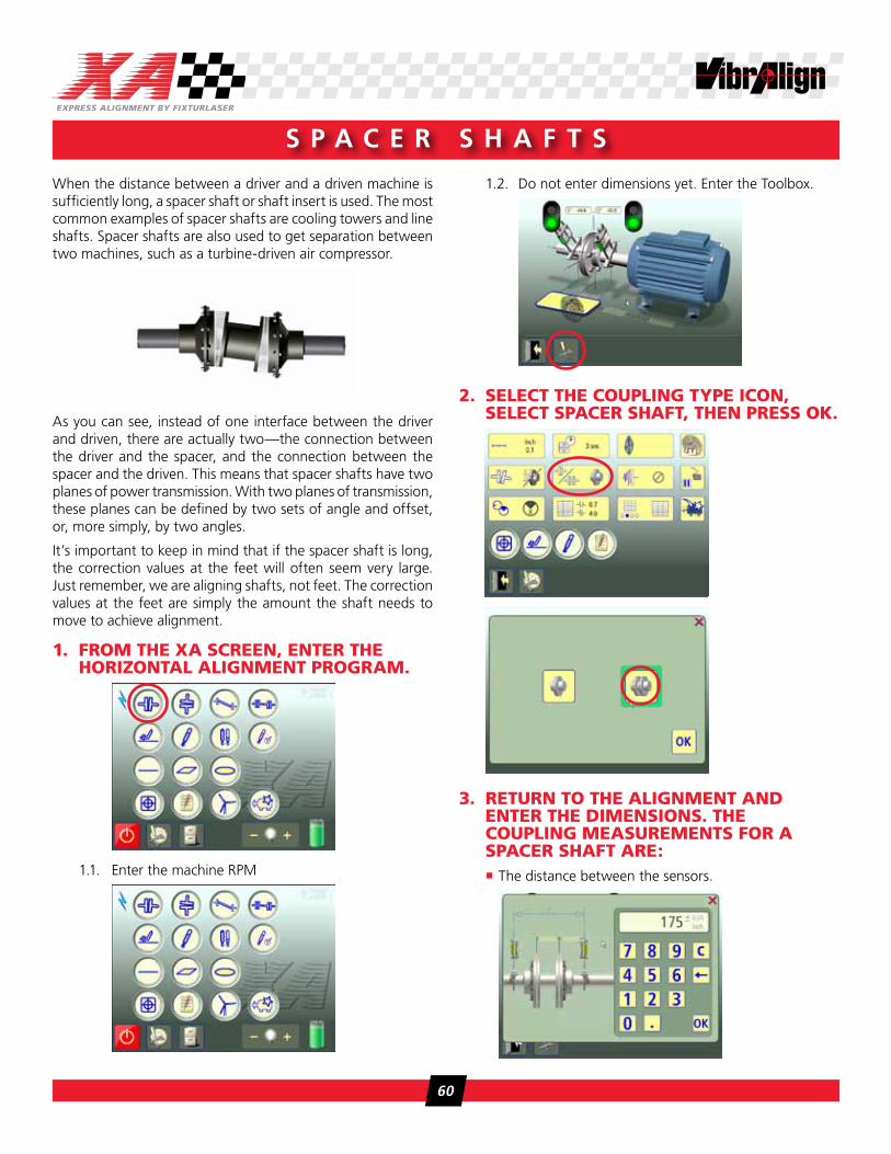
1.2. Do not enter dimensions yet. Enter the Toolbox.
2. select the cOupling type icOn, select spAceR shAFt, then pRess Ok.
3. RetuRn tO the Alignment AnD enteR the DimensiOns. the cOupling meAsuRements FOR A spAceR shAFt ARe:
� The distance between the sensors.
60

� The distance between the centers of the two coupling elements.
� The distance between the center of the coupling element closest to the movable machine and the movable machine sensor.
� Enter the remaining distances.
Take the alignment data as described in previous chapters. Once you obtain the results. You will notice a difference in the
display—results are displayed as angle/angle at the couplings. Tolerances are based on only the angle of the selected tolerance set. The movable side coupling icons correspond to the coupling that is closest to the movable machine. The stationary side coupling icons correspond to the coupling closest to the stationary machine.
The correction values at the feet of the movable machine are displayed as usual. You can use a compound move as before and correct as you would for a standard alignment.
s p a C e r s h a f T
61

a p p e n d i X d
Extended Alignment
62
e X T e n d e d a l i g n M e n T
Sometimes, physical obstructions on a machine prevent you from positioning the sensors at either the nine/three o’clock position for a horizontal move or the twelve/six o’clock position for a vertical move. Extended Alignment is an optional application that allows the user to make “live” adjustments without the sensors being level or plumb.
To use the Extended Alignment function:
1. gO tO the shAFt Alignment ApplicAtiOn tOOlBOX.
2. tOuch the eXtenDeD Alignment icOn.
3. tOuch eXtenDeD Alignment On.
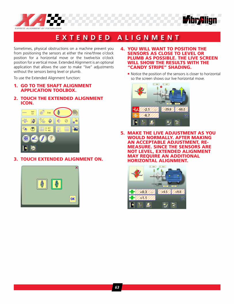
4. yOu will wAnt tO pOsitiOn the sensORs As clOse tO leVel OR plumB As pOssiBle. the liVe scReen will shOw the Results with the “cAnDy stRipe” shADing.
� Notice the position of the sensors is closer to horizontal so the screen shows our live horizontal move.
5. mAke the liVe ADjustment As yOu wOulD nORmAlly. AFteR mAking An AcceptABle ADjustment, Re-meAsuRe. since the sensORs ARe nOt leVel, eXtenDeD Alignment mAy RequiRe An ADDitiOnAl hORizOntAl Alignment.
63

a p p e n d i X e
Machine Train
64

A machine train is a set-up of more than two rotating machines that are connected to each other. A typical machine train is a motor which drives a gearbox driving a third piece of equipment. Line shafts, compressors, washers, roll drives, pumps, fans, etc. can be set up in trains of three or more.
When aligning a train of machine elements, adjusting one machine will directly affect the alignment of the other machines. Before making any adjustment in a machine train it is important to know the relative position of each machine in the train. When this is known, it is easy to get an overview of the machine train to see which adjustments are needed to align all the machines.
The amount of adjustment needed depends on which machine in the machine train is selected as the stationary machine. In many cases there are also restrictions to the amount of adjustment due to base- or bolt-bound conditions that may influence the choice of the stationary machine.
The machine train program in both the XA-D and UPAD display unit (DU) is specially designed to quickly provide an overview of the position of each machine and to determine which machine should be chosen as stationary in order to optimize the adjustment work. Functions in the program make it possible to align machines to target positions and to calculate the minimum amount of adjustment to align the entire machine train.
Once the stationary machine has been chosen, the alignment of the machine train elements is performed using the horizontal alignment program.
mounting
Mounting of the sensors is done in a similar manner to regular horizontal shaft alignments. It is important to note, though, that the sensors for the stationary and movable machine be placed on the same side of the coupling every time. Try to always be on the same side of the machine train when mounting the sensors to avoid making mistakes.
pre-Alignment setup
To minimize the time for measurements onsite, it is recommended to configure the machine and save it in memory. Distances between machine feet, location of coupling centers, machine IDs and target values can be collected ahead of time, pre-programmed and saved in the display unit for use in the field. Once on site, you simply open up the configuration from the Memory Manager and continue entering the measurements for the sensor placement around the couplings.
When collecting information on the machine elements, be sure to check to amount of adjustment possible for every machine. Estimate the amount of shims available to remove, check to see how much adjustment can be made horizontally around the bolts and check if there are any other physical restrictions such as conduit, piping, etc. This will help us determine which machine to lock as the stationary when the entire train is aligned.
1. setting up the mAchine tRAin1.1. From the Main Menu, touch the Machine Train icon.
M a C h i n e T r a i n
65

1.2. The screen shows machine trains of three, four or five elements. Select the one that corresponds to your job.
� We will proceed as if three elements were selected. The program works the same way with larger trains.
1.3. The elements are pre-named 1, 2 & 3, etc. We’ll call them motor, gearbox, pump.
1.4. Enter the appropriate machine dimensions in the dimension boxes.
� Notice that once all the dimensions have been entered, the horizontal alignment program icon appears above each coupling
� Target (thermal) values may also be entered at this time
1.5. Save the template to the DU’s memory.
1.6. If the preceding steps were done in advance,
once in the field, recall the saved machine train configuration. (See Chapter 9 on file management). Else, continue with the next step.
2. meAsuRing misAlignment cOnDitiOns
In the program, a shaft alignment measurement is first performed at each coupling. The results are then summarized for the machine train.
From the recalled template or from step 1.4 above,
2.1. Touch the first coupling icon
2.2. Enter the dimensions to locate the sensors as in previous alignments
� M sensor to S sensor
� M sensor to coupling center
2.3. Complete the alignment steps. Refer to Chapter 2 for more information.
2.4. At the results screen, touch OK.
2.5. Complete the process for the remaining couplings
� Once a coupling has been measured, the shaft alignment icon will be replaced with the remeasure icon
M a C h i n e T r a i n
66

M a C h i n e T r a i n
2.6. When all the couplings have been measured, the results screen for the entire train will be displayed.
3. eVAluAting the ResultsNow is the time to decide how to proceed with the alignment. A best fit, minimum move calculation can be performed and the XA will pick the reference machine. Or, foot values can be displayed for each machine and compared with the information you gathered during the pre-alignment setup. Either way, a reference machine has to be picked and the other machines will be moved relative to that “locked” machine.
� Results can be saved by touching the save icon
� Coupling values and foot values can be toggled to help evaluate the best move
� Touching the remeasure icon will allow you to collect another set of measurements
� The Minimum Moves icon can be touched to allow the XA to set a reference. The calculation is based on locking the machine that produces the smallest horizontal and vertical moves.
� Individual machines can be set as the stationary by touching the lock icon above the machine and the results can be re-evaluated. For example, locking the pump versus locking the motor may produce a more workable solution.
4. peRFORming the mAchine tRAin AlignmentFor this example we will pick the gearbox as the stationary reference for the alignments. Now that we have evaluated the entire situation we will perform two separate alignments. The pump will be aligned to the gearbox and then the motor will be aligned to the gearbox.
4.1. Exit the Machine Train program
4.2. From the main menu, select the horizontal alignment program
4.3. To align the pump to the gearbox, setup the M sensor on the pump. The pump will be the movable element. Setup the S sensor on the gearbox. The gearbox will be the stationary element.
4.4. Complete the alignment and save the results. Refer to Chapter 2 for details on horizontal alignments.
4.5. Return to the main menu.
4.6. Remove the sensors from the pump and gearbox shafts.
4.7. Enter the horizontal alignment program to align the motor to the gearbox
4.8. To align the motor to the gearbox, setup the M sensor on the motor. The motor will be the movable element. Setup the S sensor on the gearbox. The gearbox will be the stationary element.
4.9. Complete the alignment and save the results.
67