Embed Size (px)
Citation preview

1
TRAINING MANUAL
ON SCOUTING OF SITES
FOR PICO AND MICRO
HYDRO POWER SCHEMES
AKSM/ PA / GTZ- AMES / DIPREME Manica
ZZ~May 2009
Practical Action
GTZ-AMES Energizing
Development

2
TABLE OF CONTENT
Introduction
1. Site Identification on Maps
2. Layout of Pico / Micro Hydro Schemes and Environmental Considerations
3. Preliminary Site Visit
4. Village Meeting for Project Introductions to the Community
5. Demand Survey Format
6. Measuring Water Flow and Formats
6.1. Using Electronic Flow Meter
6.2. Using Bucket and Stop Watch Method
6.3. Using Float Method
7. Measuring Head
7.1. Using Spirit Level, Straight Edge and Line Method
7.2. Using Clinometer and Tape Measure Method
7.3. Using an Altimeter or GPS with Altimeter
7.4. Using Engineer’s Automatic Level
8. Formula for Calculations of Power
9. Transmission Power Lines and Electrical Installations
10. Financial Analysis and Viability Considerations
11. Appendix:
11.1. Survey Specific Reports
11.2. List of Participants
11.3. Training Content and Schedule
3
STEP BY STEP TRAINING
1. Site Identification on Maps
Basic knowledge of map reading is essential in
order to interpret the physical features
properly.
Based on cartographical maps identify sites
that have rivers or streams that flow over steep
slopes. Steep slopes are where the contour
ridges are very close.
Choose sites that are accessible in order to
reduce travel costs. The locations should also
save as demonstration sites for marketing
purposes to future customers.
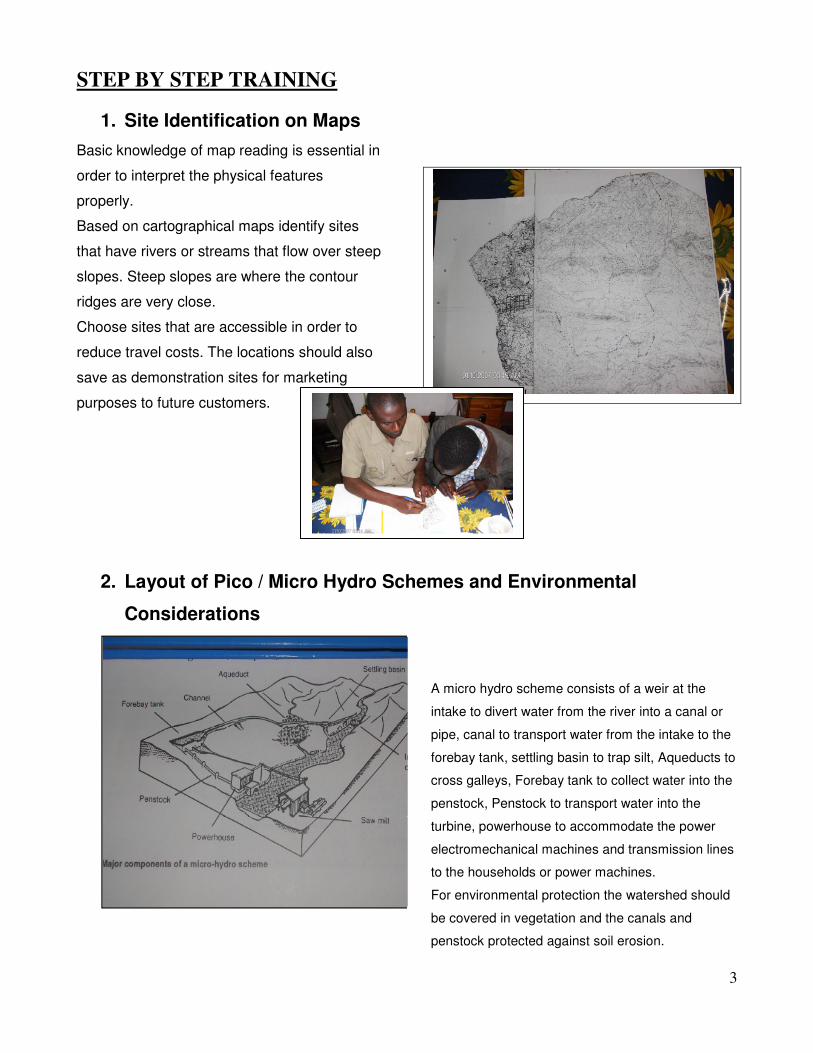
2. Layout of Pico / Micro Hydro Schemes and Environmental
Considerations
A micro hydro scheme consists of a weir at the
intake to divert water from the river into a canal or
pipe, canal to transport water from the intake to the
forebay tank, settling basin to trap silt, Aqueducts to
cross galleys, Forebay tank to collect water into the
penstock, Penstock to transport water into the
turbine, powerhouse to accommodate the power
electromechanical machines and transmission lines
to the households or power machines.
For environmental protection the watershed should
be covered in vegetation and the canals and
penstock protected against soil erosion.

4
3. Preliminary Site Visit
1. Visit the site of the intake and check on feasibility of constructing a weir.
2. Walk along the canal if it exists or along the site for the canal, assess position of forebay tank
and the penstock.
3. If a turbine already exists, assess the components and get the historical background of the
system.
4. Village Meeting for Project Introduction
Before carrying out surveys in the village there should be a meeting with the community to clarify
intentions and collect relevant information.
• Prepare meeting schedule and agenda together with partners to be involved e.g. from Department of
Energy
• Prepare information that is required e.g. project philosophy, implementation strategy, the capacity of
the MHP Systems to be considered, credit and payments procedures.
• Choose appropriate day for the meeting where people are not busy in the fields and inform them on
time. On the day of the meeting arrive on the venue on time in order not to frustrate the villagers
• During the meeting share topics accordingly. Involve the Department of Energy, the district
Infrastructure Department, environmental department.
• Check the local ability to manage the scheme and the willingness of the community to pay for
electricity
• During the meeting try to listen to the villagers as much as possible. Be more of a moderator than a
preacher. Answer questions clearly and if you do not have an answer note down the question and tell
the group you will go and research. After the research give feed back.
• Outline the conclusions of the meeting. Write minutes of the meeting and distribute the minutes to
stakeholders.

5. Demand Survey Formats
Determine whether there is a local demand for electricity or mechanical power machines like grinding mills. Use the
following format for calculation of demand in electricity.
MICRO HYDRO POWER DIMENSIONSNome de dono:
Demanda Numero de casas a beneficiar
Beneficiarios de sistema de recarga de battrias
Nome da familia GPS Data
Agregado
familiar South
TOTAL
TOTAL Watt
Demanda Total
Demand Survey Formats
whether there is a local demand for electricity or mechanical power machines like grinding mills. Use the
following format for calculation of demand in electricity.
MICRO HYDRO POWER DIMENSIONS Nome da zona:
Comunidade
Data:
Numero de casas a beneficiar Populacao
eneficiarios de sistema de recarga de battrias
Total
GPS Data Tipo Uso de energia
South East Height de
Casa
0,1,2,4 Ilumin ação Radio TV
5
whether there is a local demand for electricity or mechanical power machines like grinding mills. Use the
Data:
Populacao
TV Banca Outros

6
6. Measuring Water Flow and Formats
6.1 Electronic Flow meter (propeller)
The flow meter uses a propeller that is dipped
into the flowing water.
The instrument measures the velocity of the
flowing fluid in m/s that can then be calculated
into m3/s. It can also be programmed to
measure the flow in m3/s. The instrument also
measures temperature, pressure
Make sure that the batteries are charged
before taking the machine to the field.
6.2 Bucket and Stop Watch Method
This method is suitable for rivulets only and
water in canals.
Required equipment: 20 liter open bucket,
short piece of pipe say one meter of 100mm
diameter pvc pipe and a stop watch.
Water is dammed to flow through the pipe to
discharge into the bucket. Time taken to fill the
bucket (t) is measured and recorded in
seconds. Ten measurements are taken and
the average calculated.
The water flow (Q) is measured in liters per
second by dividing 20 liters by the time taken
to fill it up.
Q [l/s] = 20 / t
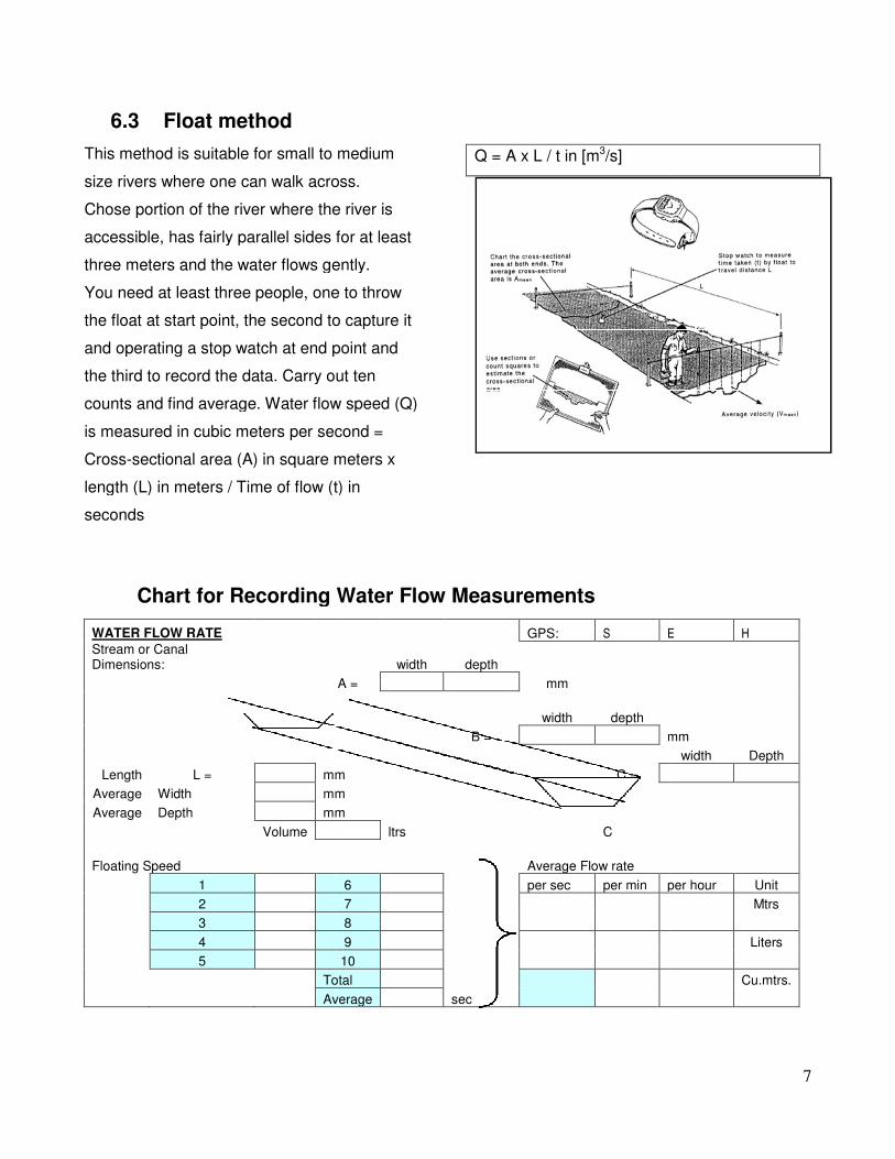
6.3 Float method
This method is suitable for small to medium
size rivers where one can walk across.
Chose portion of the river where the river is
accessible, has fairly parallel sides for at least
three meters and the water flows gently.
You need at least three people, one to throw
the float at start point, the second to capture it
and operating a stop watch at end point and
the third to record the data. Carry out ten
counts and find average. Water flow speed (Q)
is measured in cubic meters per second =
Cross-sectional area (A) in square meters x
length (L) in meters / Time of flow (t) in
seconds
Chart for Recording Water Flow Measurements
WATER FLOW RATE
Stream or Canal Dimensions:
Length L = mm
Average Width mm
Average Depth mm
Volume
Floating Speed
1
2
3
4
5
Total
Average
This method is suitable for small to medium
can walk across.
Chose portion of the river where the river is
accessible, has fairly parallel sides for at least
three meters and the water flows gently.
e to throw
the float at start point, the second to capture it
and operating a stop watch at end point and
the third to record the data. Carry out ten
counts and find average. Water flow speed (Q)
is measured in cubic meters per second =
a (A) in square meters x
length (L) in meters / Time of flow (t) in
Q = A x L / t in [m3/s]
or Recording Water Flow Measurements
GPS: S E
width depth
A = mm
width depth
B = mm
mm C =
mm
mm
ltrs C
Average Flow rate
6 per sec per min per hour
7
8
9
10
Total
Average sec
7
E H
mm
width Depth
per hour Unit
Mtrs
Liters
Cu.mtrs.

8
7. Measuring the Head
7.1 Spirit level / straight edge and line
Using a vertical ranging rod, a timber straight
edge with a spirit level (the straight edge is
calibrated or supported with a tape measure)
progressively measure vertical and horizontal
distances from the position of the powerhouse
to the position of the forebay tank and also
measure the distance on the slope.
Record the measurement on a chart and
calculate the head and the length of the
penstock.
Data Recording Chart
Horizontal (A) Vertical (B) Slope (C)
1
2
3
4
5
6
7
8
9
10
11
Total

9
7.2 Clinometer and Tape Measure
Also known as an Abbey level is a small version of a line level that is used to measure vertical angles.
This is used to measure the angle of the slope. Two points are marked using two strong pegs of equal
size (1,5m long). With a tape measure of 20 to 50m for measuring the distance between two points,
Ds. The vertical angle is measured by placing the Clinometer on top of the first peg placed at the
position of the turbine base and sighting the second peg. Record the measured angle. Move the first
peg to the third position along the route of the penstock and repeat the measurement.
Head (H) is calculated as H = Ds x sinαααα
Accuracy level about +/- 5%
7.3 Engineer’s Automatic Dumpy Level
The dumpy level is used in areas that are cleared without tree obstructions. The operator (qualified
operators only) measures the horizontal line on the staff (3 to 5m) that is held upright by the second
person.
7.4 Using Altimeter or GPS with Inbuilt Altimeter
Measuring with altimeter simply means taking the reading at the
positions of the powerhouse and the fore-bay tank and
calculating the difference. N.B. that the accuracy is affected by
atmospheric pressure and temperature.
10
8. Formula for Calculations of Power
Make preliminary estimation of the power to be generated by calculating using the measured head (H)
and water flow (Q) using the following formula:
P = 5xHxQ
P = Power in KW
H = Head in meters
Q = Water Flow in cu.mtrs/sec
The amount of power will determine whether the scheme is suitable for mechanical poert or for
electricity generation or for both.
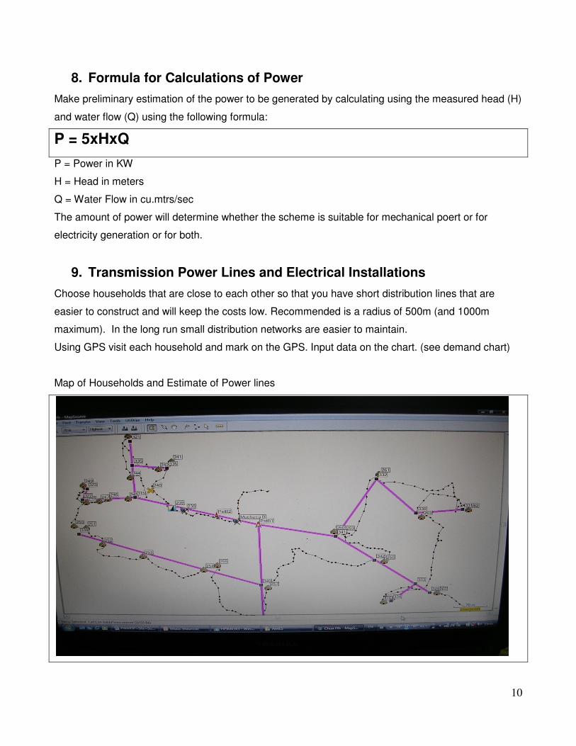
9. Transmission Power Lines and Electrical Installations
Choose households that are close to each other so that you have short distribution lines that are
easier to construct and will keep the costs low. Recommended is a radius of 500m (and 1000m
maximum). In the long run small distribution networks are easier to maintain.
Using GPS visit each household and mark on the GPS. Input data on the chart. (see demand chart)
Map of Households and Estimate of Power lines

11
10. Financial Analysis and Viability Considerations
Calculate the required capital by estimating the bills of materials required for the scheme
Establish the source of key components like turbines, alternators, electrical cables
Call for quotations from reputable suppliers (at least 3 quotations)
Seek quotations from contractors for the electrical installation as well as mechanical
installations.
Estimate of Running costs, the Income and Profit for the operator and loan repayment rates.
COST ANALYSIS CALCULATIONS FOR MICRO HYDRO POWER
ACTIVITY Amount
1 Feasibility and design Study
2 Civil Works
3 Intake
4 Canal
5 Fore-bay tank
6 Penstock + supports -
7 Power house and other civil corks
8 Turbine improvements
9 Alternator
10 Electronic Load Control
11 Main Electric Power lines incl. instr. box
12 Household Electric Installations
TOTAL Project Considerations
Loan for Households
Loan for Mill Operator
Subsidy offered by Project
Discounted Annual Payments for Operator
A= C x j(1 + j)^n
(1 + j)^n-1 Where
A= discounted annual repayment
C = original capital sum
n = loan period in years
j = interest rate
A = discounted annual Op. loan repayment
Op. Loan Repayment per month
Number of Households connected
Average loan repayment per Household per month
Considered collections for consumption
Mthly charge per h/hold f. Consumption
Number of households
Monthly revenue collected
Annual gross revenue collected
Maintenance Budget
Annual Maintenance budget @ 10%
Income for Mill operator
Annual net revenue collected
12
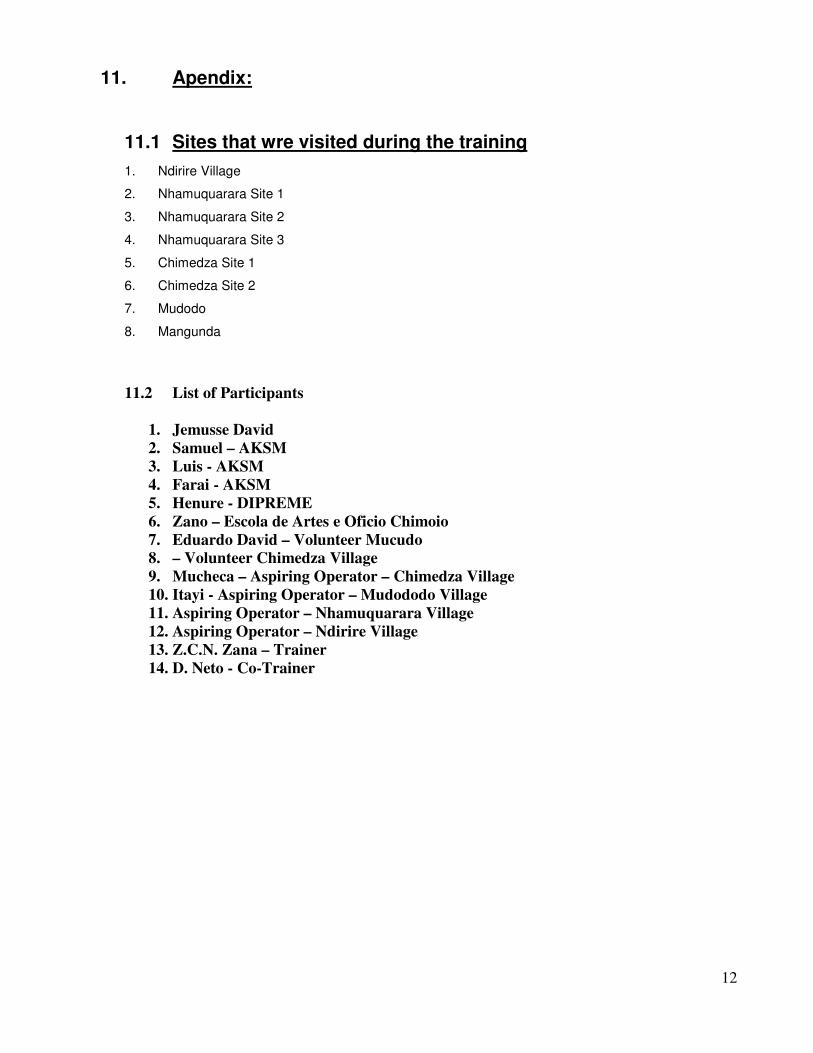
11. Apendix:
11.1 Sites that wre visited during the training
1. Ndirire Village
2. Nhamuquarara Site 1
3. Nhamuquarara Site 2
4. Nhamuquarara Site 3
5. Chimedza Site 1
6. Chimedza Site 2
7. Mudodo
8. Mangunda
11.2 List of Participants
1. Jemusse David 2. Samuel – AKSM 3. Luis - AKSM 4. Farai - AKSM 5. Henure - DIPREME 6. Zano – Escola de Artes e Oficio Chimoio 7. Eduardo David – Volunteer Mucudo 8. – Volunteer Chimedza Village 9. Mucheca – Aspiring Operator – Chimedza Village 10. Itayi - Aspiring Operator – Mudododo Village 11. Aspiring Operator – Nhamuquarara Village 12. Aspiring Operator – Ndirire Village 13. Z.C.N. Zana – Trainer 14. D. Neto - Co-Trainer

13
TREINAMENTO EM PESQUISA DE ESQUEMAS DE PICO E MICRO HYDRO CONTEÚDO E PLANO DE TREINANDO 1. Treinamento teórico (1 dia) 1.1 Identificação de local nas Mapas 1.2 Formatos de Pesquisa de demanda 1.3 Plano de Esquemas de Pico / Micro Hidro e Considerações Ambientais 1.4 Teoria de Medir Fluxo de Água e Formatos 1.5 Teoria de Medir a Desnível (head) 1.6 Formula para Cálculos de Potência 1.7 Rede de transmissão de tenção e Instalações Elétricas 1.8 Análise financeira e Considerações de Viabilidade 2. Campo prático que Treina (4 dias) 2.1 Identificação de local nas sítios 2.2 Reuniões local de Pesquisa de demanda 2.3 Medição de Fluxo de Água 2.4 Plano Esquema 2.5 Aspectos ambientais 2.6 Medição de Desnível 2.7 Cálculos técnicos de Potência 2.8 Rede de transmissão de tenção e Instalações Elétricas 3. Análise financeira e Considerações de Viabilidade (2 dias) 3.1 Estimativa de Capital 3.2 Estimativa de custos de Operação 3.3 Estimativa de Renda 4. Relatórios de pesquisa (2 a 3 dias dependem de número de locais) 4.1 local 1 4.2 local 2 4.3 local 3 4.4 local 4 4.5 etc