Embed Size (px)
Citation preview
Training manualIndraControl L40Revision 10 / 2004
MobileHydraulics
ServiceAutomationPneumatics
Linear MotionAssembly Technologies
Electric Drivesand Controls
IndustrialHydraulics
didactic from Rexroth. Systematic Success
Revision10 / 2004
IndralControl L40
Imprint
Issuer:Bosch Rexroth AGService Automationdidactic
Author: Heribert Wolf BRS / DID2
Zu diesem Buch: − Da dieses Buch nicht zum autodidaktischen Lernen erstelltwurde, ergeben sich Zusammenhänge erst durch dieErläuterungen im Seminar.
− Es sind auf jeden Fall die Informationen und Anweisungen zu den Produkten gehörenden Veröffentlichungen derBosch Rexroth AG zu beachten.
− Teilweise sind Abbildungen falsch. Diese werden im Seminarmit Korrekturen versehen und erklärt.
To this manual: − Because this manual was not designed for autodidaktic studies,the background story is understandable sometimesonly with the explanations during the seminar.
− In any way the informations and instructions of the publications assigned to the Products byBosch Rexroth AG must be regarded.
− Sometimes screens are not correct. They are explained and corrected during the seminar.
Technical EditorLayout: Volker Seipel
© 2004Bosch Rexroth AGGeschäftsbereich Service Automationdidactic
Alle Rechte bei Bosch Rexroth AG, All rights at Bosch Rexroth AGauch für den Fall von Schutzrechtsanmeldungen. also in the case of announcements for industrial property rightsJede Verfügungsbefugnis, wie Kopier- und Each authority for disposal, copiing rights and Weitegaberecht, bei uns. the rights for transmission are at our company.
Irrtum und technische Änderungen vorbehalten. There are errors expected and the subject may change without a notice.
Imprint Nachdruck, Vervielfältigung undÜbersetzung, auch auszugsweise,
Issuer: nur mit unserer vorherigen schrift-Bosch Rexroth AG lichen Zustimmung und mit Quellen-Service Automation angabe gestattet. Wir übernehmendidactic keine Haftung für die Übereinstim-
mung des Inhalts mit den jeweilsgeltenden gesetzlichen Vorschriften.
Reproduction, copying, or trans-lation of this publication, wholly orin part, only with our previous writtenpermission and with source credit.We assume no responsibility foragreement of the contents with locallaws and regulations.Bosch Rexroth AG is exempt fromliability, and reserves the right tomake changes at any time.
Author: Heribert Wolf BRS / DID2
Technical EditorLayout: Volker Seipel
1. Print run 2004
© 2004Bosch Rexroth AGBusiness division Service Automationdidactic
1didactic from Rexroth
xx/03 1070 087xxx-1xx
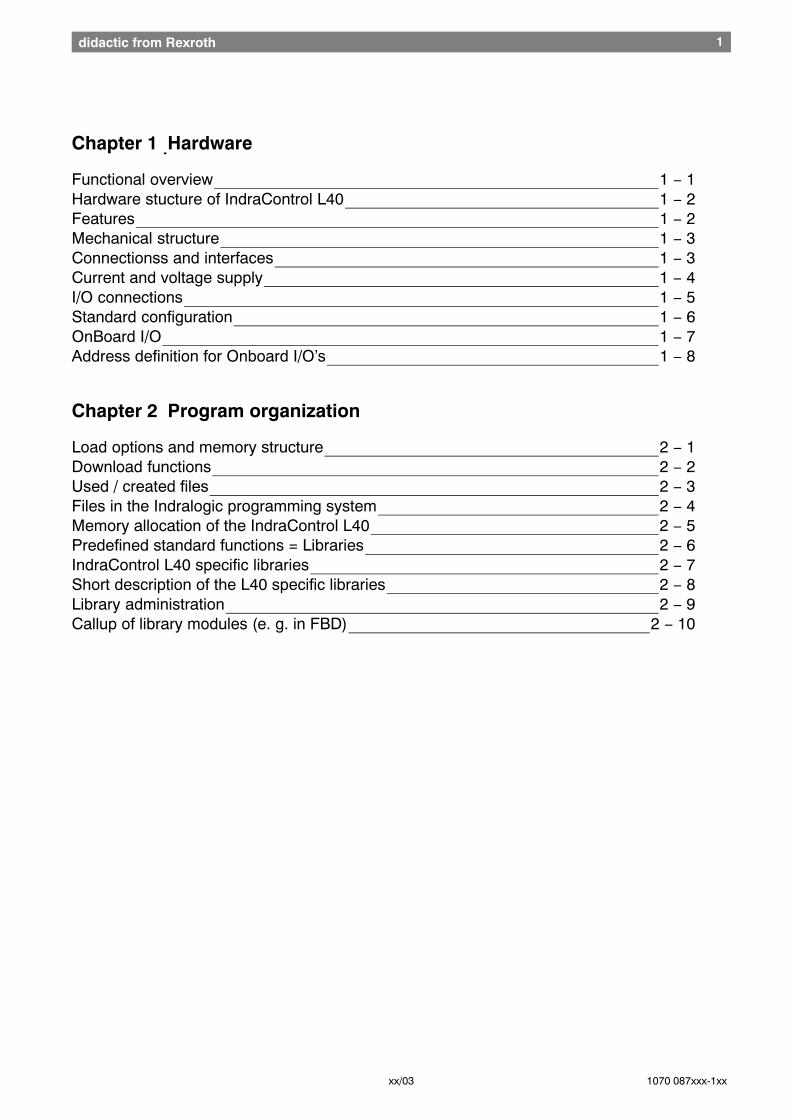
Chapter 1 Hardware
Functional overview 1 − 1 Hardware stucture of IndraControl L40 1 − 2 Features 1 − 2 Mechanical structure 1 − 3 Connectionss and interfaces 1 − 3 Current and voltage supply 1 − 4 I/O connections 1 − 5 Standard configuration 1 − 6 OnBoard I/O 1 − 7 Address definition for Onboard I/O’s 1 − 8
Chapter 2 Program organization
Load options and memory structure 2 − 1 Download functions 2 − 2 Used / created files 2 − 3 Files in the Indralogic programming system 2 − 4 Memory allocation of the IndraControl L40 2 − 5 Predefined standard functions = Libraries 2 − 6 IndraControl L40 specific libraries 2 − 7 Short description of the L40 specific libraries 2 − 8 Library administration 2 − 9 Callup of library modules (e. g. in FBD) 2 − 10
2didactic from Rexroth
xx/03 1070 087xxx-1xx
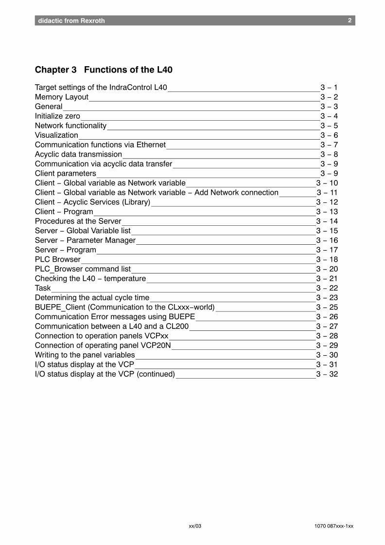
Chapter 3 Functions of the L40
Target settings of the IndraControl L40 3 − 1 Memory Layout 3 − 2 General 3 − 3 Initialize zero 3 − 4 Network functionality 3 − 5 Visualization 3 − 6 Communication functions via Ethernet 3 − 7 Acyclic data transmission 3 − 8 Communication via acyclic data transfer 3 − 9 Client parameters 3 − 9 Client − Global variable as Network variable 3 − 10 Client − Global variable as Network variable − Add Network connection 3 − 11 Client − Acyclic Services (Library) 3 − 12 Client − Program 3 − 13 Procedures at the Server 3 − 14 Server − Global Variable list 3 − 15 Server − Parameter Manager 3 − 16 Server − Program 3 − 17 PLC Browser 3 − 18 PLC_Browser command list 3 − 20 Checking the L40 − temperature 3 − 21 Task 3 − 22 Determining the actual cycle time 3 − 23 BUEPE_Client (Communication to the CLxxx−world) 3 − 25 Communication Error messages using BUEPE 3 − 26 Communication between a L40 and a CL200 3 − 27 Connection to operation panels VCPxx 3 − 28 Connection of operating panel VCP20N 3 − 29 Writing to the panel variables 3 − 30 I/O status display at the VCP 3 − 31 I/O status display at the VCP (continued) 3 − 32
Hardware L40 1didactic from Rexroth
Chapter 1L40 Hardware
Nachdruck, Vervielfältigung und Übersetzung, auch auszugsweise,nur mit unserer vorherigen schriftlichen Zustimmung und mit Quellenangabe
gestattet. Wir übernehmen keine Haftung für die Übereinstimmungdes Inhalts mit den jeweils geltenden gesetzlichen Vorschriften.
Reproduction, copying, or translation of this publication, wholly orin part, only with our previous written permission and with source credit.
We assume no responsibility for agreement of the contents with locallaws and regulations Bosch Rexroth AG is exempt from
liability, and reserves the right to make changes at any time.
Hardware 1 − 1didactic from Rexroth
Didactic 10/2004 Indracontrol L40
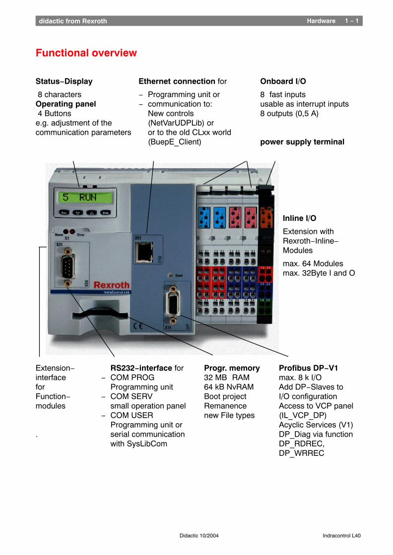
Functional overview
Status−Display Ethernet connection for Onboard I/O
8 characters − Programming unit or 8 fast inputsOperating panel − communication to: usable as interrupt inputs 4 Buttons New controls 8 outputs (0,5 A)e.g. adjustment of the (NetVarUDPLib) orcommunication parameters or to the old CLxx world
(BuepE_Client) power supply terminal
Inline I/O
Extension withRexroth−Inline−Modules
max. 64 Modulesmax. 32Byte I and O
Extension− RS232−interface for Progr. memory Profibus DP−V1interface − COM PROG 32 MB RAM max. 8 k I/Ofor Programming unit 64 kB NvRAM Add DP−Slaves toFunction− − COM SERV Boot project I/O configurationmodules small operation panel Remanence Access to VCP panel
− COM USER new File types (IL_VCP_DP)Programming unit or Acyclic Services (V1)
. serial communication DP_Diag via functionwith SysLibCom DP_RDREC,
DP_WRREC
Hardware 1 − 2didactic from Rexroth
Didactic 10/2004 Indracontrol L40
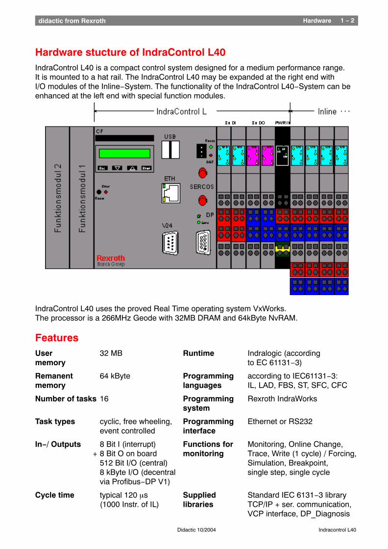
Hardware stucture of IndraControl L40IndraControl L40 is a compact control system designed for a medium performance range.It is mounted to a hat rail. The IndraControl L40 may be expanded at the right end withI/O modules of the Inline−System. The functionality of the IndraControl L40−System can beenhanced at the left end with special function modules.
IndraControl L40 uses the proved Real Time operating system VxWorks.The processor is a 266MHz Geode with 32MB DRAM and 64kByte NvRAM.
FeaturesUser 32 MB Runtime Indralogic (according memory to EC 61131−3)
Remanent 64 kByte Programming according to IEC61131−3:memory languages IL, LAD, FBS, ST, SFC, CFC
Number of tasks 16 Programming Rexroth IndraWorkssystem
Task types cyclic, free wheeling, Programming Ethernet or RS232event controlled interface
In−/ Outputs 8 Bit I (interrupt) Functions for Monitoring, Online Change, + 8 Bit O on board monitoring Trace, Write (1 cycle) / Forcing,
512 Bit I/O (central) Simulation, Breakpoint,8 kByte I/O (decentral single step, single cyclevia Profibus−DP V1)
Cycle time typical 120 µs Supplied Standard IEC 6131−3 library(1000 Instr. of IL) libraries TCP/IP + ser. communication,
VCP interface, DP_Diagnosis
Hardware 1 − 3didactic from Rexroth
Didactic 10/2004 Indracontrol L40
Mechanical structureThe IndraControl L40 is mounted to a standard hat rail according to DIN EN50022. (35mm x 7,5mm)
Note: Beside the mounting function, the hat rail also has the function of grounding and is additionally used for heat conduction.
This means, that the hat rail must always be connected to a grounding bus. Additional the heat is partial conducted via the hat rail. So it is used in conjunction with themetallic ground plate of the L40 as a cooling element.
The power supply voltages and the Onboard− in− and Outputs are wired via theInline− terminals. Sensors and actors at the Onboard− I/O’s are connected with a 2−wiretechnique (Sensors with 24V and signal, actors with signal and 0V).
The connection terminals for all wires are facing located at the front side of the housing.The bending radius should not exceed 120mm.
Because of its low protection category IP20, the IndraControl L40 must be mounted inside ofa control cabinet or a similar housing. The prefered mounting position is horizontal. Due to thermic reasons, a vertical mounting isnot recommended.
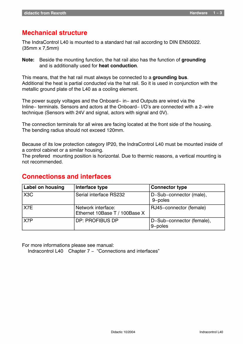
Connectionss and interfaces
Label on housing Interface type Connector type
X3C Serial interface RS232 D−Sub−connector (male), 9−poles
X7E Network interface:Ethernet 10Base T / 100Base X
RJ45−connector (female)
X7P DP: PROFIBUS DP D−Sub−connector (female),9−poles
For more informations please see manual:Indracontrol L40 Chapter 7 − “Connections and interfaces”
Hardware 1 − 4didactic from Rexroth
Didactic 10/2004 Indracontrol L40
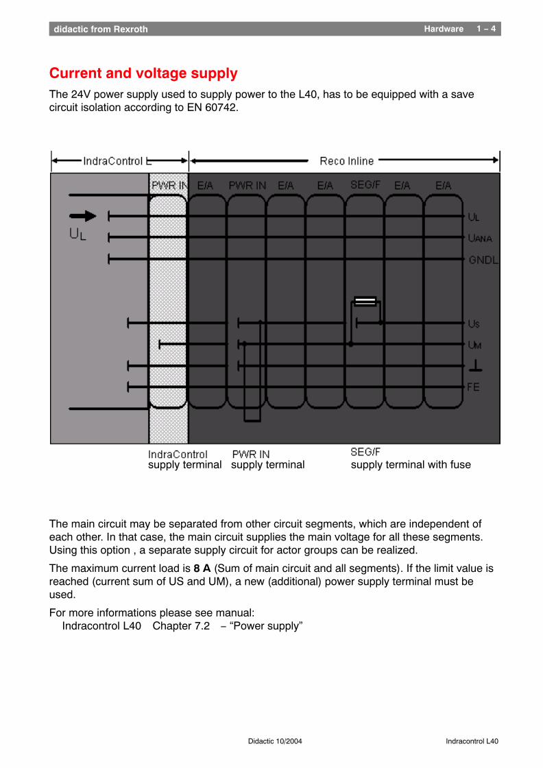
Current and voltage supplyThe 24V power supply used to supply power to the L40, has to be equipped with a savecircuit isolation according to EN 60742.
supply terminal supply terminal supply terminal with fuse
The main circuit may be separated from other circuit segments, which are independent ofeach other. In that case, the main circuit supplies the main voltage for all these segments. Using this option , a separate supply circuit for actor groups can be realized.
The maximum current load is 8 A (Sum of main circuit and all segments). If the limit value isreached (current sum of US and UM), a new (additional) power supply terminal must beused.
For more informations please see manual:Indracontrol L40 Chapter 7.2 − “Power supply”
E/A−Verarbeitung Hardware 1 − 5didactic from Rexroth
Didactic 10/2004 Indracontrol L40
I/O connections
I
N
T
E
R
B
U
S
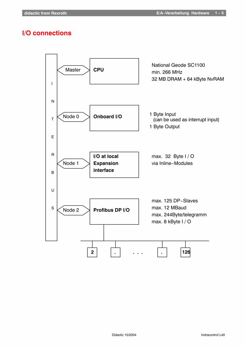
CPU
Onboard I/O
I/O at localExpansioninterface
Profibus DP I/O
1 Byte Input (can be used as interrupt input)1 Byte Output
max. 125 DP−Slavesmax. 12 MBaudmax. 244Byte/telegrammmax. 8 kByte I / O
max. 32 Byte I / Ovia Inline−Modules
Master
Node 1
Node 0
Node 2
. . .2 126..
National Geode SC1100min. 266 MHz32 MB DRAM + 64 kByte NvRAM
I/O configuration 1 − 6didactic from Rexroth
Didactic 10/2004 Indracontrol L40
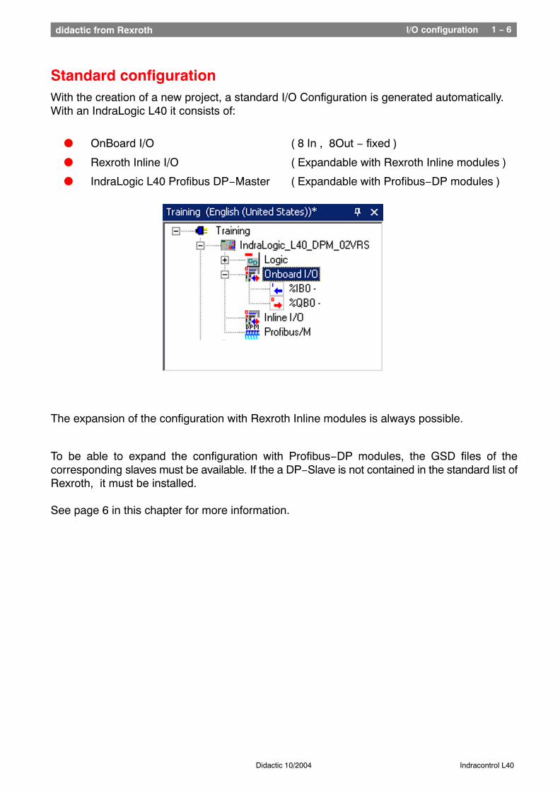
Standard configurationWith the creation of a new project, a standard I/O Configuration is generated automatically.With an IndraLogic L40 it consists of:
l OnBoard I/O ( 8 In , 8Out − fixed )
l Rexroth Inline I/O ( Expandable with Rexroth Inline modules )
l IndraLogic L40 Profibus DP−Master ( Expandable with Profibus−DP modules )
The expansion of the configuration with Rexroth Inline modules is always possible.
To be able to expand the configuration with Profibus−DP modules, the GSD files of thecorresponding slaves must be available. If the a DP−Slave is not contained in the standard list ofRexroth, it must be installed.
See page 6 in this chapter for more information.
I/O configuration 1 − 7didactic from Rexroth
Didactic 10/2004 Indracontrol L40
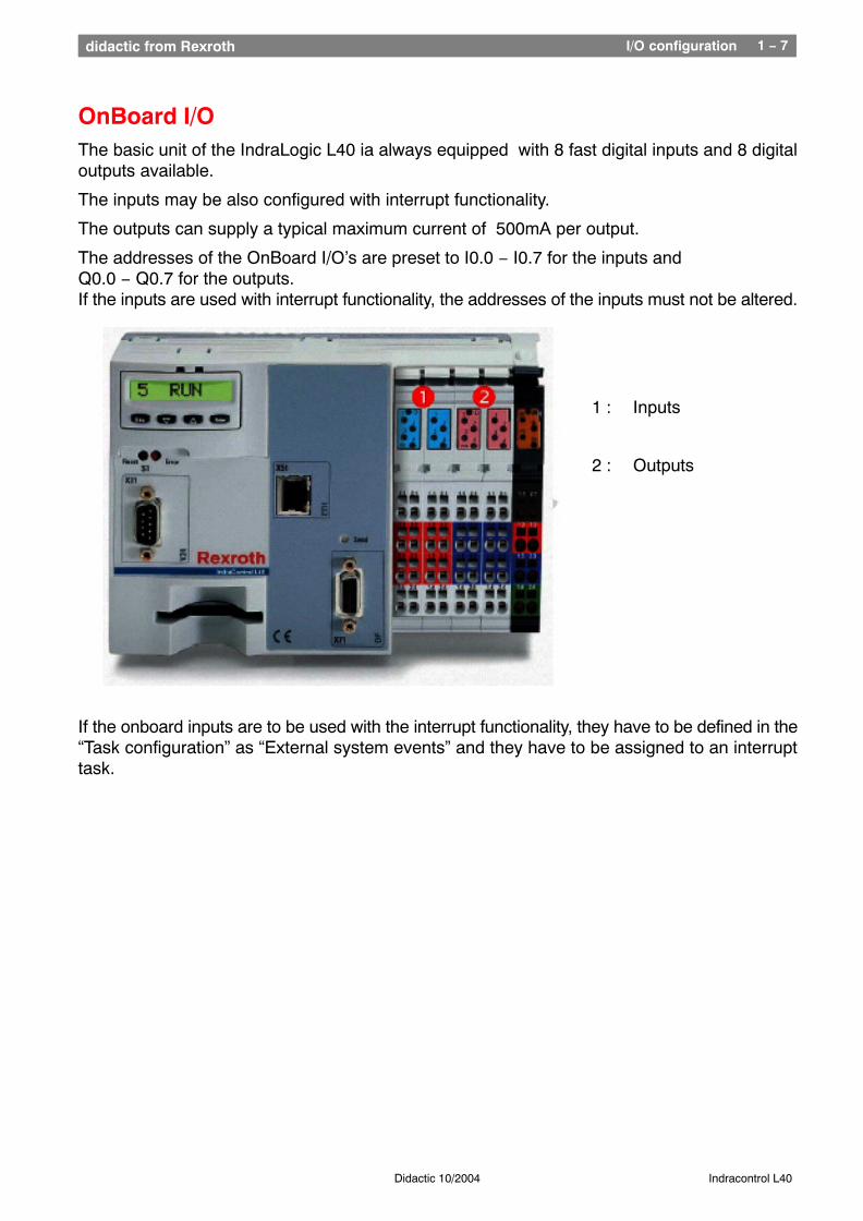
OnBoard I/OThe basic unit of the IndraLogic L40 ia always equipped with 8 fast digital inputs and 8 digitaloutputs available.
The inputs may be also configured with interrupt functionality.
The outputs can supply a typical maximum current of 500mA per output.
The addresses of the OnBoard I/O’s are preset to I0.0 − I0.7 for the inputs and Q0.0 − Q0.7 for the outputs. If the inputs are used with interrupt functionality, the addresses of the inputs must not be altered.
1 : Inputs
2 : Outputs
If the onboard inputs are to be used with the interrupt functionality, they have to be defined in the“Task configuration” as “External system events” and they have to be assigned to an interrupttask.
I/O configuration 1 − 8didactic from Rexroth
Didactic 10/2004 Indracontrol L40
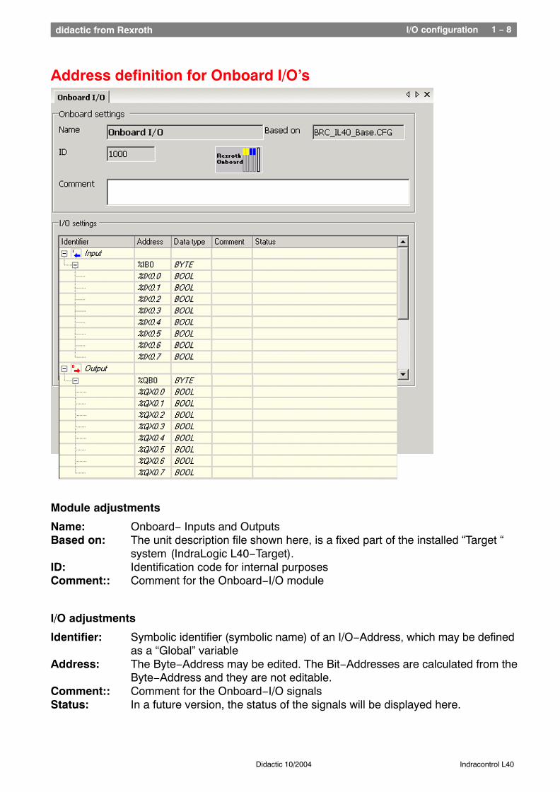
Address definition for Onboard I/O’s
Module adjustments
Name: Onboard− Inputs and OutputsBased on: The unit description file shown here, is a fixed part of the installed “Target “
system (IndraLogic L40−Target).ID: Identification code for internal purposesComment:: Comment for the Onboard−I/O module
I/O adjustments
Identifier: Symbolic identifier (symbolic name) of an I/O−Address, which may be defined as a “Global” variable
Address: The Byte−Address may be edited. The Bit−Addresses are calculated from theByte−Address and they are not editable.
Comment:: Comment for the Onboard−I/O signalsStatus: In a future version, the status of the signals will be displayed here.
Program organization 1didactic from Rexroth
Chapter 2Program
organization
Nachdruck, Vervielfältigung und Übersetzung, auch auszugsweise,nur mit unserer vorherigen schriftlichen Zustimmung und mit Quellenangabe
gestattet. Wir übernehmen keine Haftung für die Übereinstimmungdes Inhalts mit den jeweils geltenden gesetzlichen Vorschriften.
Reproduction, copying, or translation of this publication, wholly orin part, only with our previous written permission and with source credit.
We assume no responsibility for agreement of the contents with locallaws and regulations Bosch Rexroth AG is exempt from
liability, and reserves the right to make changes at any time.

Program organisation 2 − 1didactic from Rexroth
Didactic 10/2004 Indracontrol L40
Load options and memory structure
PC with Indralogic
newly loaded program
actually executedprogram
Boot project
Name :Default.prg
Sourcecode(compressedSourcecode)
Name :Source.DAT
IndralogicProject file
On
line
“Cre
ate
bo
ot
pro
ject
”
So
urc
e co
de
do
wn
load
Rel
oad
of
pro
gra
m a
fter
a n
ew s
tart
*.PRO
32MB RAM
32 MB FLASH−Card
64 kB NvRAM
Remanent Data
Login
Program organisation 2 − 2didactic from Rexroth
Didactic 10/2004 Indracontrol L40
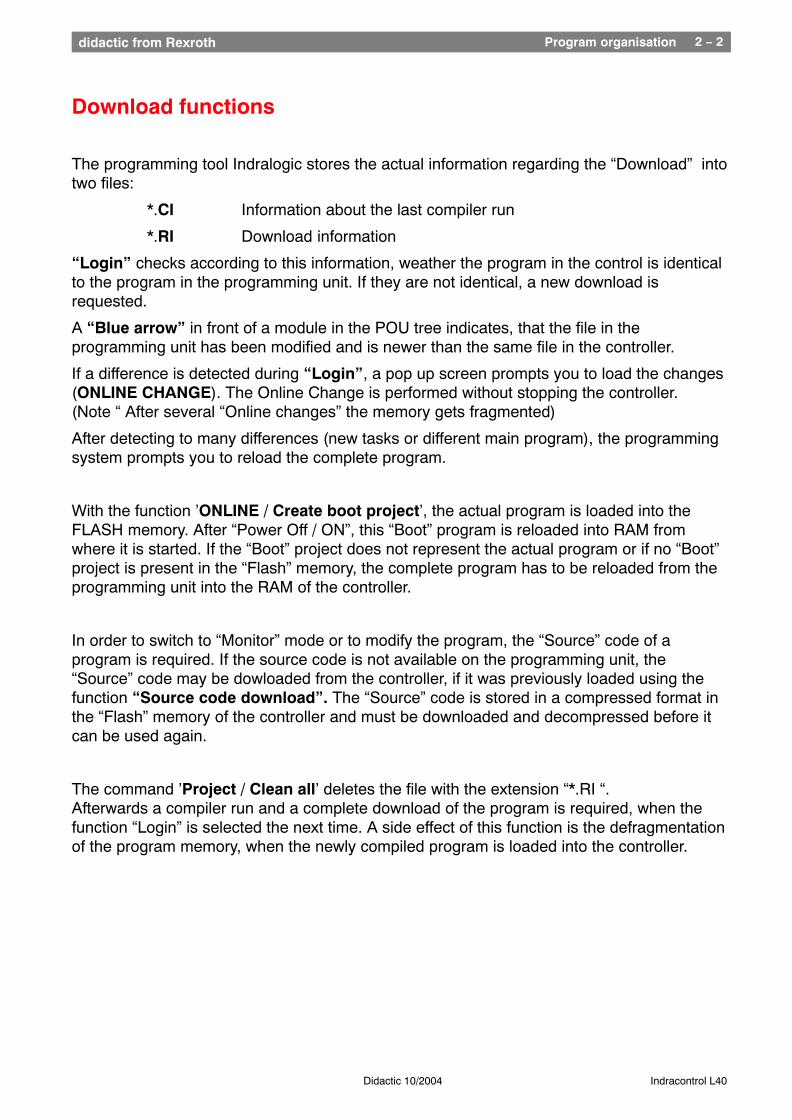
Download functions
The programming tool Indralogic stores the actual information regarding the “Download” intotwo files:
*.CI Information about the last compiler run
*.RI Download information
“Login” checks according to this information, weather the program in the control is identicalto the program in the programming unit. If they are not identical, a new download isrequested.
A “Blue arrow” in front of a module in the POU tree indicates, that the file in theprogramming unit has been modified and is newer than the same file in the controller.
If a difference is detected during “Login”, a pop up screen prompts you to load the changes(ONLINE CHANGE). The Online Change is performed without stopping the controller.(Note “ After several “Online changes” the memory gets fragmented)
After detecting to many differences (new tasks or different main program), the programmingsystem prompts you to reload the complete program.
With the function ’ONLINE / Create boot project’, the actual program is loaded into theFLASH memory. After “Power Off / ON”, this “Boot” program is reloaded into RAM fromwhere it is started. If the “Boot” project does not represent the actual program or if no “Boot”project is present in the “Flash” memory, the complete program has to be reloaded from theprogramming unit into the RAM of the controller.
In order to switch to “Monitor” mode or to modify the program, the “Source” code of aprogram is required. If the source code is not available on the programming unit, the“Source” code may be dowloaded from the controller, if it was previously loaded using thefunction “Source code download”. The “Source” code is stored in a compressed format inthe “Flash” memory of the controller and must be downloaded and decompressed before itcan be used again.
The command ’Project / Clean all’ deletes the file with the extension “*.RI “.Afterwards a compiler run and a complete download of the program is required, when thefunction “Login” is selected the next time. A side effect of this function is the defragmentationof the program memory, when the newly compiled program is loaded into the controller.
Program organisation 2 − 3didactic from Rexroth
Didactic 10/2004 Indracontrol L40
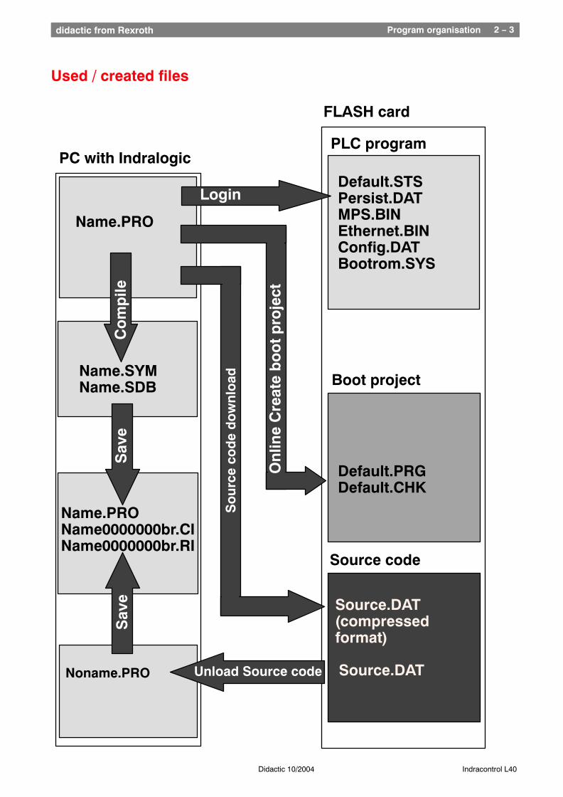
Used / created files
Name.SYMName.SDB
PC with Indralogic
FLASH card
Default.STSPersist.DATMPS.BINEthernet.BINConfig.DATBootrom.SYS
Default.PRGDefault.CHK
Source.DAT(compressedformat)
Login
Pro
gra
mm
neu
lad
en n
ach
Neu
star
t
Name.PRO
Co
mp
ile
Boot project
PLC program
On
line
Cre
ate
bo
ot
pro
ject
So
urc
e co
de
do
wn
load
Source code
Unload Source code Source.DATNoname.PRO
Sav
e
Name.PROName0000000br.CIName0000000br.RI
Sav
e
Program organisation 2 − 4didactic from Rexroth
Didactic 10/2004 Indracontrol L40
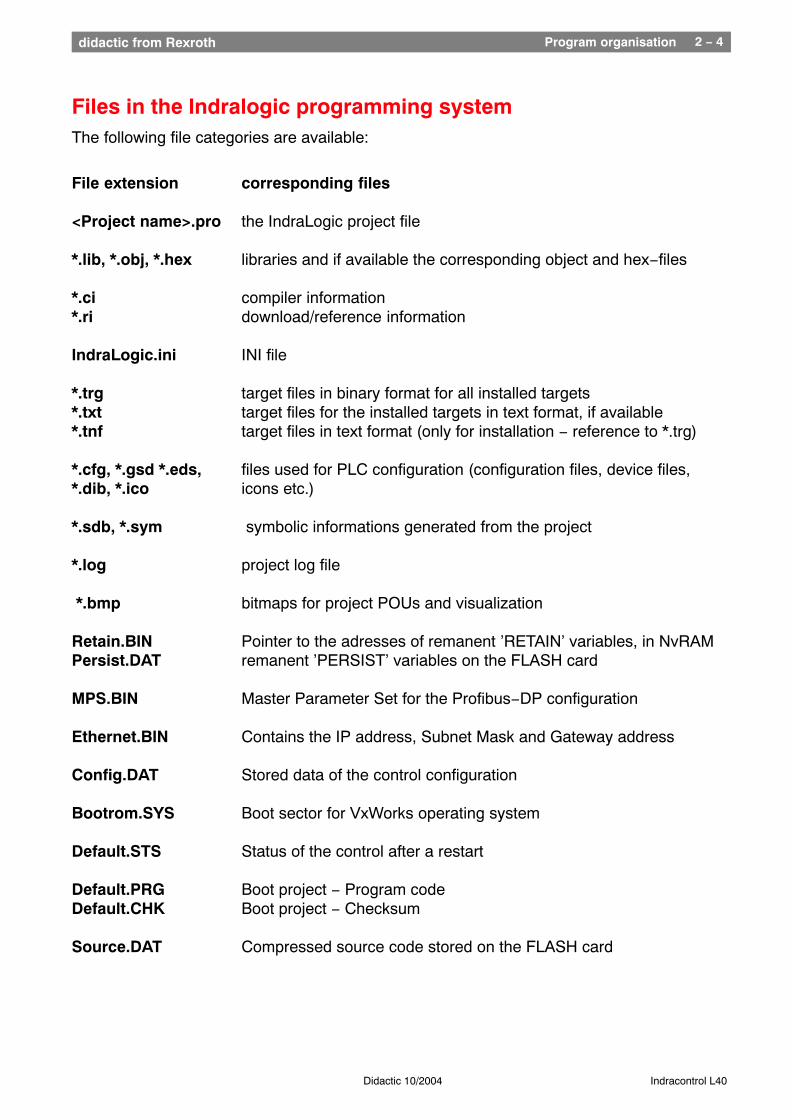
Files in the Indralogic programming systemThe following file categories are available:
File extension corresponding files
<Project name>.pro the IndraLogic project file *.lib, *.obj, *.hex libraries and if available the corresponding object and hex−files *.ci compiler information *.ri download/reference information IndraLogic.ini INI file
*.trg target files in binary format for all installed targets*.txt target files for the installed targets in text format, if available*.tnf target files in text format (only for installation − reference to *.trg)
*.cfg, *.gsd *.eds, files used for PLC configuration (configuration files, device files, *.dib, *.ico icons etc.) *.sdb, *.sym symbolic informations generated from the project
*.log project log file *.bmp bitmaps for project POUs and visualization
Retain.BIN Pointer to the adresses of remanent ’RETAIN’ variables, in NvRAM Persist.DAT remanent ’PERSIST’ variables on the FLASH card
MPS.BIN Master Parameter Set for the Profibus−DP configuration
Ethernet.BIN Contains the IP address, Subnet Mask and Gateway address
Config.DAT Stored data of the control configuration
Bootrom.SYS Boot sector for VxWorks operating system
Default.STS Status of the control after a restart
Default.PRG Boot project − Program codeDefault.CHK Boot project − Checksum
Source.DAT Compressed source code stored on the FLASH card
Program organisation 2 − 5didactic from Rexroth
Didactic 10/2004 Indracontrol L40
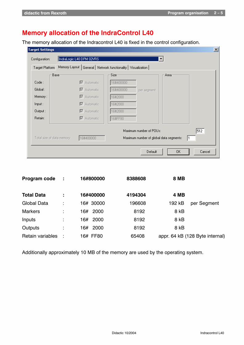
Memory allocation of the IndraControl L40The memory allocation of the Indracontrol L40 is fixed in the control configuration.
Program code : 16#800000 8388608 8 MB
Total Data : 16#400000 4194304 4 MB
Global Data : 16# 30000 196608 192 kB per Segment
Markers : 16# 2000 8192 8 kB
Inputs : 16# 2000 8192 8 kB
Outputs : 16# 2000 8192 8 kB
Retain variables : 16# FF80 65408 appr. 64 kB (128 Byte internal)
Additionally approximately 10 MB of the memory are used by the operating system.
Programm Organization 2 − 6didactic from Rexroth
Didactic 10/2004 Indracontrol L40
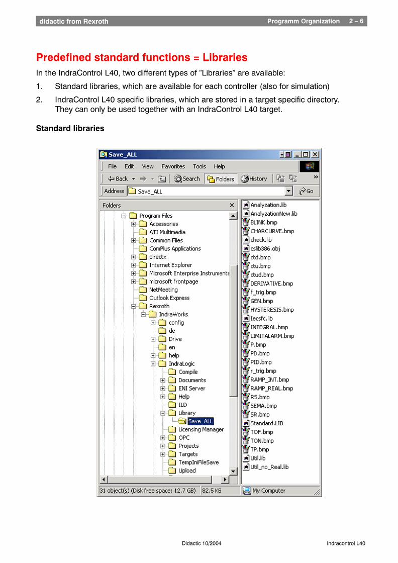
Predefined standard functions = LibrariesIn the IndraControl L40, two different types of ”Libraries” are available:
1. Standard libraries, which are available for each controller (also for simulation)
2. IndraControl L40 specific libraries, which are stored in a target specific directory. They can only be used together with an IndraControl L40 target.
Standard libraries
Programm Organization 2 − 7didactic from Rexroth
Didactic 10/2004 Indracontrol L40
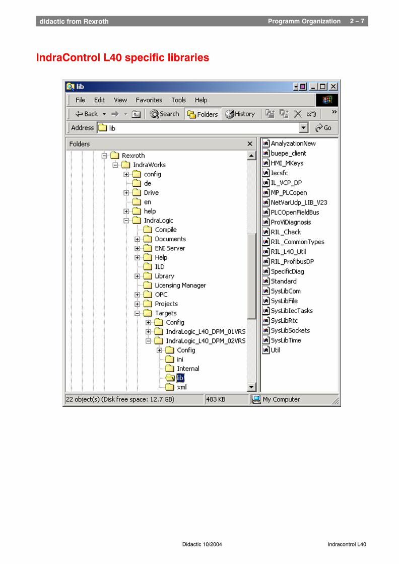
IndraControl L40 specific libraries
Programm Organization 2 − 8didactic from Rexroth
Didactic 10/2004 Indracontrol L40
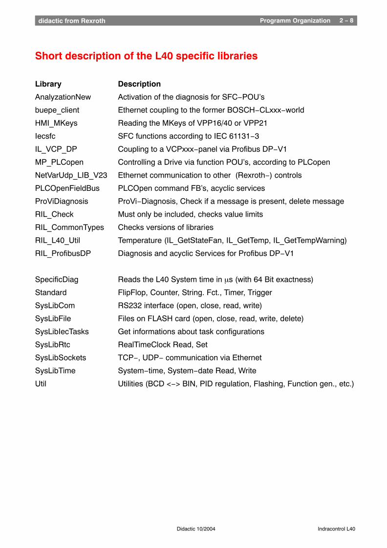
Short description of the L40 specific libraries
Library Description
AnalyzationNew Activation of the diagnosis for SFC−POU’s
buepe_client Ethernet coupling to the former BOSCH−CLxxx−world
HMI_MKeys Reading the MKeys of VPP16/40 or VPP21
Iecsfc SFC functions according to IEC 61131−3
IL_VCP_DP Coupling to a VCPxxx−panel via Profibus DP−V1
MP_PLCopen Controlling a Drive via function POU’s, according to PLCopen
NetVarUdp_LIB_V23 Ethernet communication to other (Rexroth−) controls
PLCOpenFieldBus PLCOpen command FB’s, acyclic services
ProViDiagnosis ProVi−Diagnosis, Check if a message is present, delete message
RIL_Check Must only be included, checks value limits
RIL_CommonTypes Checks versions of libraries
RIL_L40_Util Temperature (IL_GetStateFan, IL_GetTemp, IL_GetTempWarning)
RIL_ProfibusDP Diagnosis and acyclic Services for Profibus DP−V1
SpecificDiag Reads the L40 System time in µs (with 64 Bit exactness)
Standard FlipFlop, Counter, String. Fct., Timer, Trigger
SysLibCom RS232 interface (open, close, read, write)
SysLibFile Files on FLASH card (open, close, read, write, delete)
SysLibIecTasks Get informations about task configurations
SysLibRtc RealTimeClock Read, Set
SysLibSockets TCP−, UDP− communication via Ethernet
SysLibTime System−time, System−date Read, Write
Util Utilities (BCD <−> BIN, PID regulation, Flashing, Function gen., etc.)
Programm Organization 2 − 9didactic from Rexroth
Didactic 10/2004 Indracontrol L40
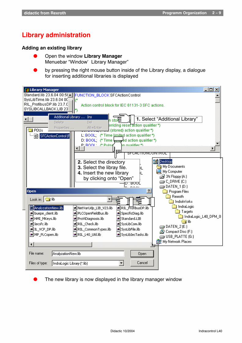
Library administration
Adding an existing library
l Open the window Library Manager Menuebar “Window’ Library Manager”
l by pressing the right mouse button inside of the Library display, a dialogue for inserting additional libraries is displayed
2. Select the directory3. Select the libray file.4. Insert the new library
by clicking onto “Open”
1. Select “Additional Library”
l The new library is now displayed in the library manager window
Programm Organization 2 − 10didactic from Rexroth
Didactic 10/2004 Indracontrol L40
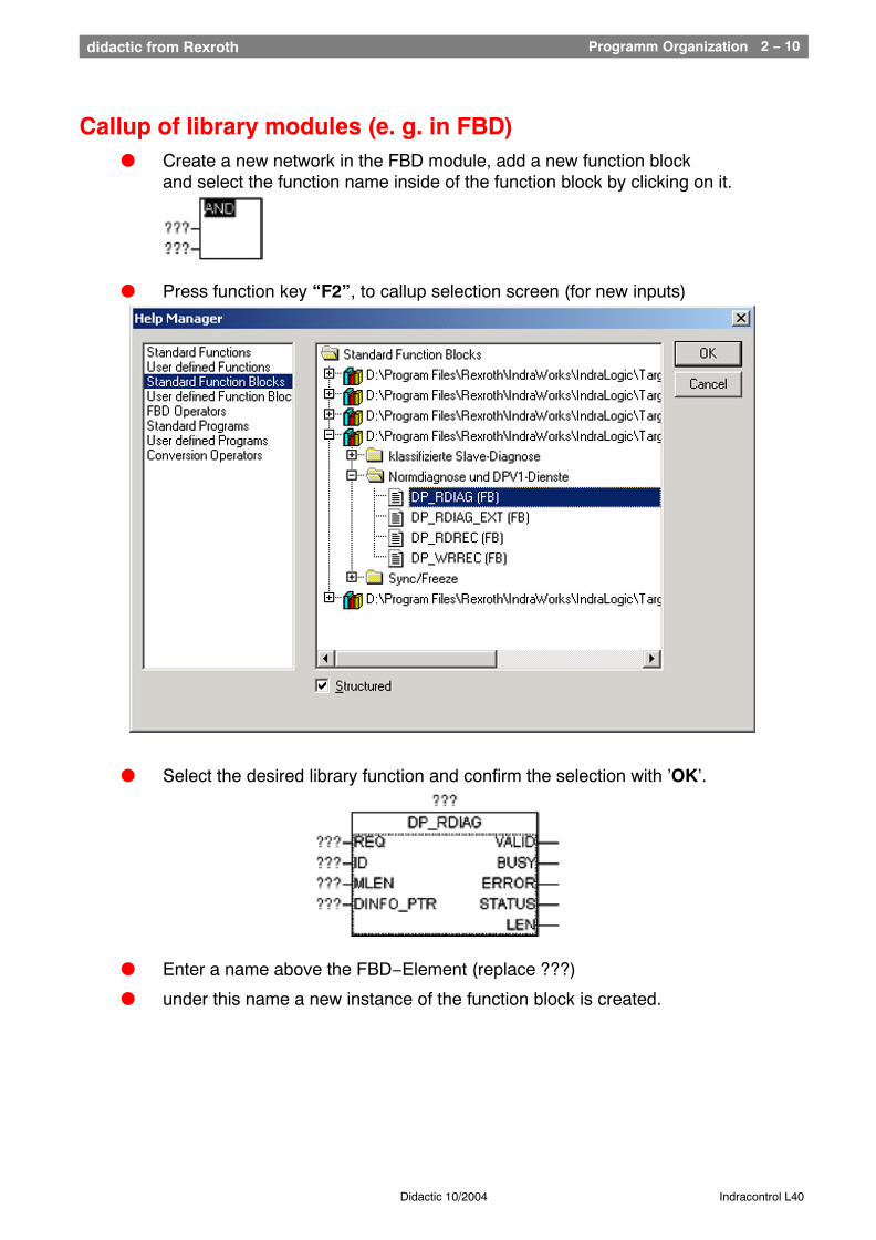
Callup of library modules (e. g. in FBD)l Create a new network in the FBD module, add a new function block
and select the function name inside of the function block by clicking on it.
l Press function key “F2”, to callup selection screen (for new inputs)
l Select the desired library function and confirm the selection with ’OK’.
l Enter a name above the FBD−Element (replace ???)
l under this name a new instance of the function block is created.
Programm Organization 2 − 11didactic from Rexroth
Didactic 10/2004 Indracontrol L40
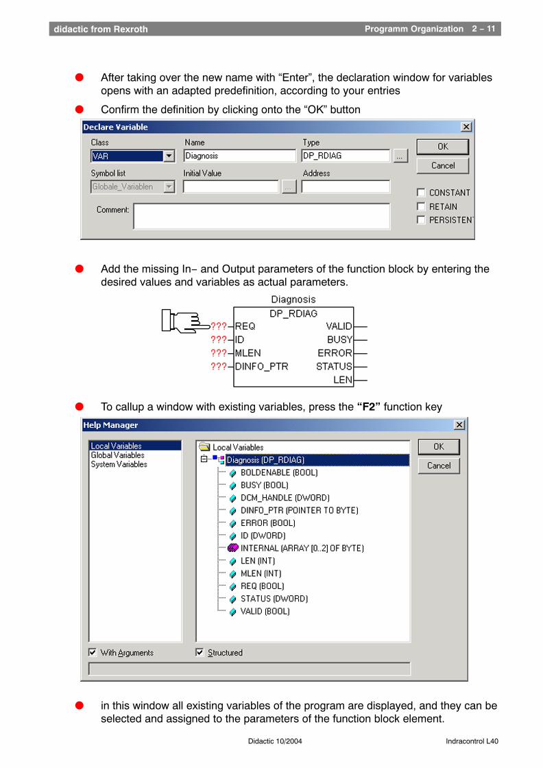
l After taking over the new name with “Enter”, the declaration window for variablesopens with an adapted predefinition, according to your entries
l Confirm the definition by clicking onto the “OK” button
l Add the missing In− and Output parameters of the function block by entering the desired values and variables as actual parameters.
l To callup a window with existing variables, press the “F2” function key
l in this window all existing variables of the program are displayed, and they can be selected and assigned to the parameters of the function block element.
Functions of the L40 1didactic from Rexroth
Chapter 3Functions of the L40
Nachdruck, Vervielfältigung und Übersetzung, auch auszugsweise,nur mit unserer vorherigen schriftlichen Zustimmung und mit Quellenangabe
gestattet. Wir übernehmen keine Haftung für die Übereinstimmungdes Inhalts mit den jeweils geltenden gesetzlichen Vorschriften.
Reproduction, copying, or translation of this publication, wholly orin part, only with our previous written permission and with source credit.
We assume no responsibility for agreement of the contents with locallaws and regulations Bosch Rexroth AG is exempt from
liability, and reserves the right to make changes at any time.
Functions of the L40 3 − 1didactic from Rexroth
Didactic 10/2004 Indracontrol L40
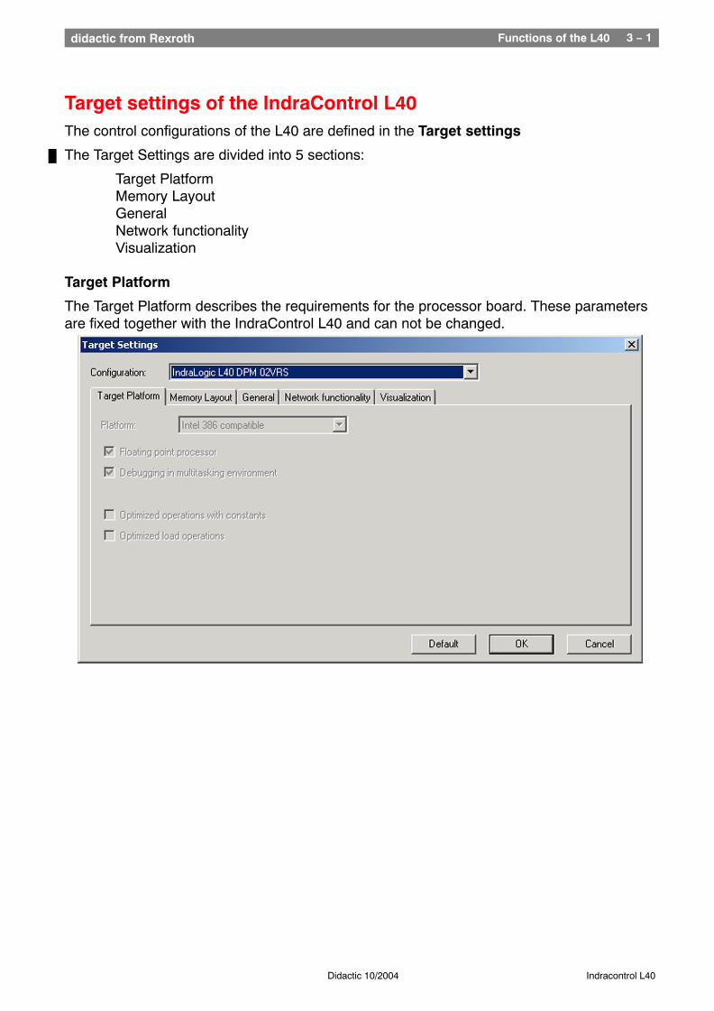
Target settings of the IndraControl L40The control configurations of the L40 are defined in the Target settings
The Target Settings are divided into 5 sections:
Target PlatformMemory LayoutGeneralNetwork functionalityVisualization
Target Platform
The Target Platform describes the requirements for the processor board. These parametersare fixed together with the IndraControl L40 and can not be changed.
Functions of the L40 3 − 2didactic from Rexroth
Didactic 10/2004 Indracontrol L40
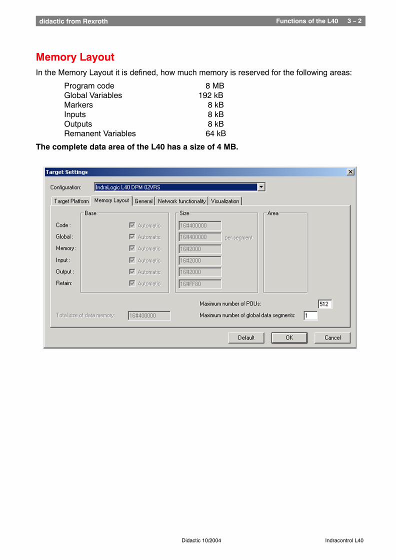
Memory LayoutIn the Memory Layout it is defined, how much memory is reserved for the following areas:
Program code 8 MBGlobal Variables 192 kBMarkers 8 kBInputs 8 kB
Outputs 8 kB Remanent Variables 64 kB
The complete data area of the L40 has a size of 4 MB.
Functions of the L40 3 − 3didactic from Rexroth
Didactic 10/2004 Indracontrol L40
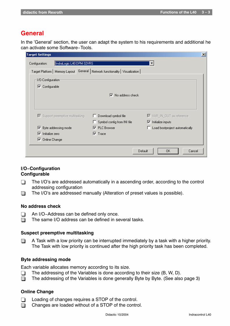
GeneralIn the ’General’ section, the user can adapt the system to his requirements and additional hecan activate some Software−Tools.
I/O−Configuration Configurable
− The I/O’s are addressed automatically in a ascending order, according to the control addressing configuration
= The I/O’s are addressed manually (Alteration of preset values is possible).
No address check
− An I/O−Address can be defined only once.= The same I/O address can be defined in several tasks.
Suspect preemptive multitasking
= A Task with a low priority can be interrupted immediately by a task with a higher priority.The Task with low priority is continued after the high priority task has been completed.
Byte addressing mode
Each variable allocates memory according to its size.− The addressing of the Variables is done according to their size (B, W, D).= The addressing of the Variables is done generally Byte by Byte. (See also page 3)
Online Change
− Loading of changes requires a STOP of the control. = Changes are loaded without of a STOP of the control.
Functions of the L40 3 − 4didactic from Rexroth
Didactic 10/2004 Indracontrol L40
Initialize zero− Variables are not changed − that means they are not initialized.= During start up, variables are set to their preset−value in the definition window or if no
value was predefined, to zero.
Download symbol file
Symbol files are used as address references for external OPC−Clients or for theCommunication requests of VCP− or VPP − Panels. They are generated, if the checkbox in’Project / Options / Symbol configuration’ is checked.
− The Symbol file is not loaded into the L40= The Symbol file is loaded into the L40
Symbol config from INI file
− The Symbol configuration is defined in ’Project’ / Options’ under the function’Configure symbol file’ .
= The Symbol configuration is read out of the INDRALOGIC.INI file. The button’Configure symbol file’ is not available with this selection.
PLC Browser
The PLC Browser is a tool, which can communicate with the L40 via command linecommands
− The PLC Browser is not available in the Resources.= The PLC Browser is available in the Resources.
Trace
The Trace function makes available a 8−channel Oscilloscope for digital and analoguevalues, which can be used to monitor “Global” − Variables.
− Trace is not available in the Resources.= Trace is available in the Resources.
VAR_IN_OUT as reference
= IN_OUT−Variables are represented by a pointer, that means, they can be used as an input and output parameter at the same time. This makes it possible to read informationfrom the calling POU and to write back values to the calling POU..
Initialize inputs
− The inputs are set to undefined values until the first bus cycle has been completed.= During the startup of the control, the inputs are preset to 0.
Load boot project automatically
− The boot project must be updated manually with the command ’Online / Create boot project’ in the L40.
= The Boot project is updated with each “LogIn” (Load / Online Change) in the L40 Flash−Memory
Functions of the L40 3 − 5didactic from Rexroth
Didactic 10/2004 Indracontrol L40
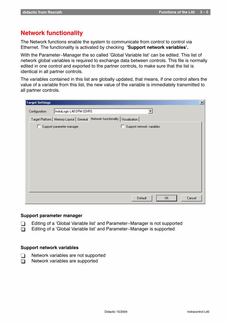
Network functionalityThe Network functions enable the system to communicate from control to control viaEthernet. The functionality is activated by checking ’Support network variables’.
With the Parameter−Manager the so called ’Global Variable list’ can be edited. This list ofnetwork global variables is required to exchange data between controls. This file is normallyedited in one control and exported to the partner controls, to make sure that the list isidentical in all partner controls.
The variables contained in this list are globally updated, that means, if one control alters thevalue of a variable from this list, the new value of the variable is immediately transmitted toall partner controls.
Support parameter manager
− Editing of a ’Global Variable list’ and Parameter−Manager is not supported= Editing of a ’Global Variable list’ and Parameter−Manager is supported
Support network variables
− Network variables are not supported= Network variables are supported
Functions of the L40 3 − 6didactic from Rexroth
Didactic 10/2004 Indracontrol L40
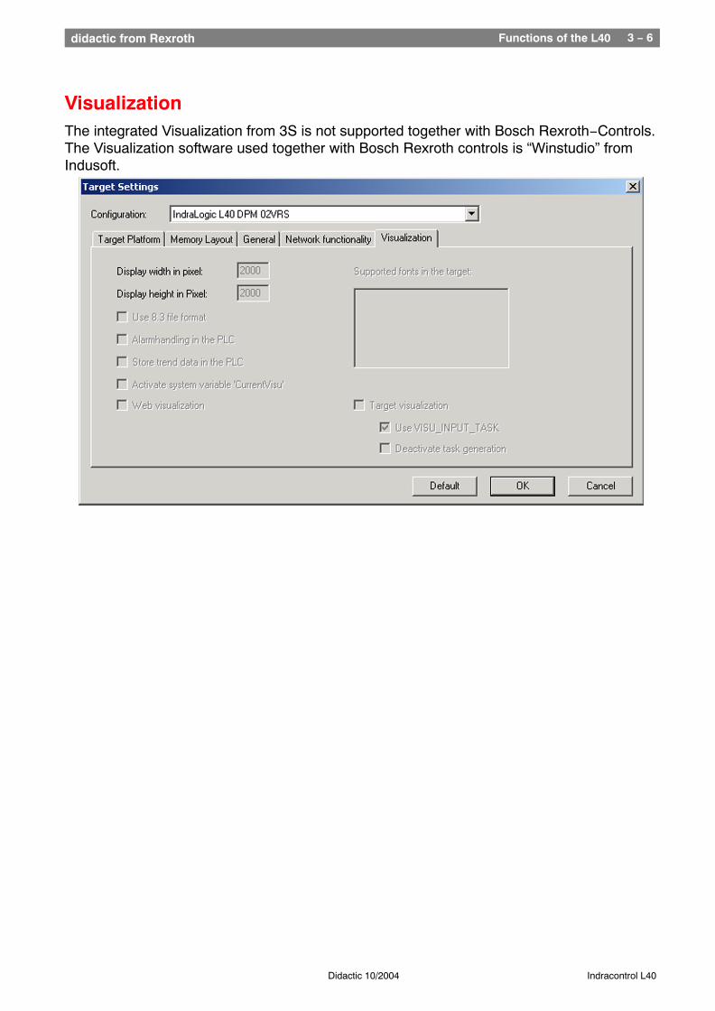
VisualizationThe integrated Visualization from 3S is not supported together with Bosch Rexroth−Controls.The Visualization software used together with Bosch Rexroth controls is “Winstudio” fromIndusoft.
Functions of the L40 3 − 7didactic from Rexroth
Didactic 10/2004 Indracontrol L40
Communication functions via EthernetThe Indralogic L40 control can communicate with two different control generations.
With the ’old BOSCH−Control’ generation and with the new Bosch Rexroth controlgeneration.
Bosch CLxxx Control generation
Connection is accomplished via Ethernet, using an interface module like the ’COM−E’ card. The library ’BUEPE_Client’ is provided to control communication in an L40 program.In this communication, the L40 is always the active partner (controls communication) and theCLxxx−control acts as a Server (supplies information).
Bosch Rexroth new Control generation
The new control generation like L40, VPP21 etc., communicates via Network functions.
The following communication types are available:
Acyclic data transfer with support of library functions (NetVarUDP_LIB_V23.lib)
This type of communication uses normal communication telegrams to exchange information.This communication type puts only a light load onto the network and the access to partnersoutside of the actual segment is possible.
Functions of the L40 3 − 8didactic from Rexroth
Didactic 10/2004 Indracontrol L40
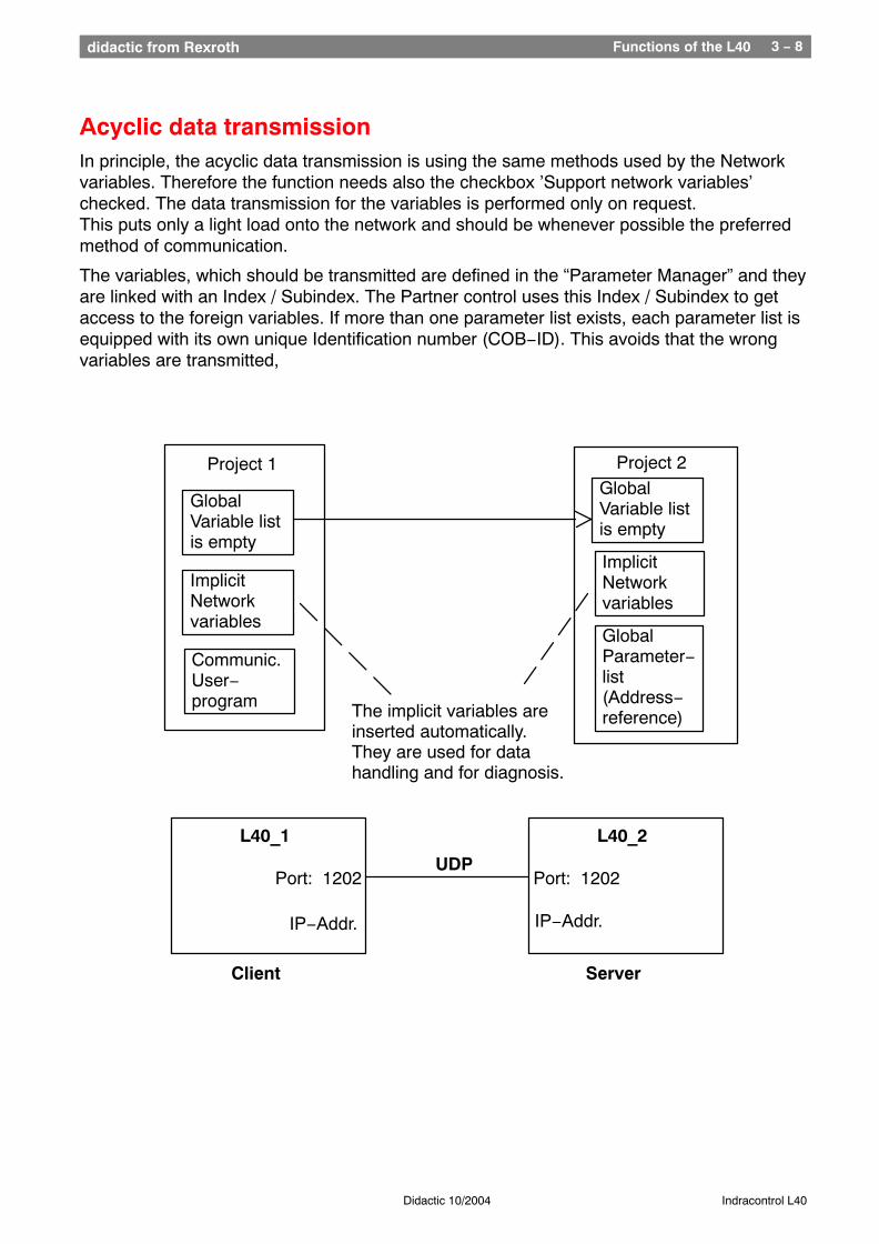
Acyclic data transmissionIn principle, the acyclic data transmission is using the same methods used by the Networkvariables. Therefore the function needs also the checkbox ’Support network variables’checked. The data transmission for the variables is performed only on request.This puts only a light load onto the network and should be whenever possible the preferredmethod of communication.
The variables, which should be transmitted are defined in the “Parameter Manager” and theyare linked with an Index / Subindex. The Partner control uses this Index / Subindex to getaccess to the foreign variables. If more than one parameter list exists, each parameter list isequipped with its own unique Identification number (COB−ID). This avoids that the wrongvariables are transmitted,
Project 1
GlobalVariable listis empty
ImplicitNetworkvariables
Project 2GlobalVariable listis empty
ImplicitNetworkvariables
L40_1
Port: 1202
IP−Addr.
L40_2
Port: 1202
IP−Addr.
UDP
Client Server
Communic.User−program
GlobalParameter−list (Address−reference)The implicit variables are
inserted automatically.They are used for datahandling and for diagnosis.
Functions of the L40 3 − 9didactic from Rexroth
Didactic 10/2004 Indracontrol L40
Communication via acyclic data transfer
Client parameters
Client − Target Settings
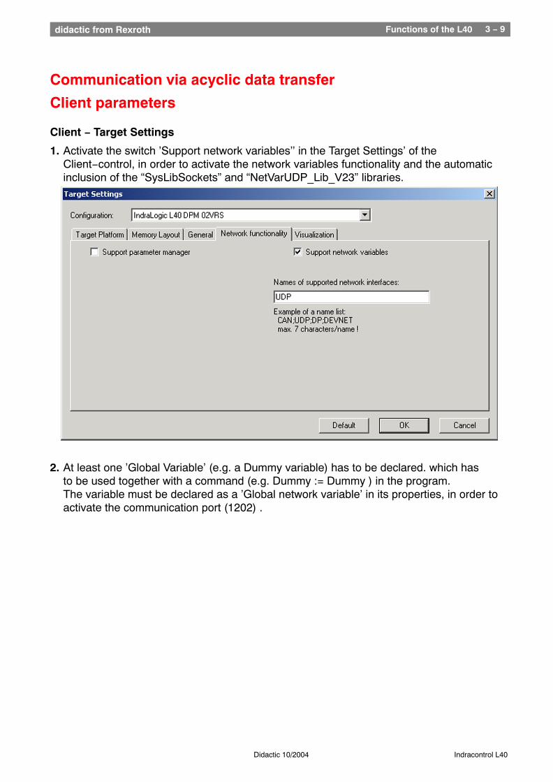
1. Activate the switch ’Support network variables’’ in the Target Settings’ of the Client−control, in order to activate the network variables functionality and the automatic inclusion of the “SysLibSockets” and “NetVarUDP_Lib_V23” libraries.
2. At least one ’Global Variable’ (e.g. a Dummy variable) has to be declared. which has to be used together with a command (e.g. Dummy := Dummy ) in the program.The variable must be declared as a ’Global network variable’ in its properties, in order to activate the communication port (1202) .
Functions of the L40 3 − 10didactic from Rexroth
Didactic 10/2004 Indracontrol L40
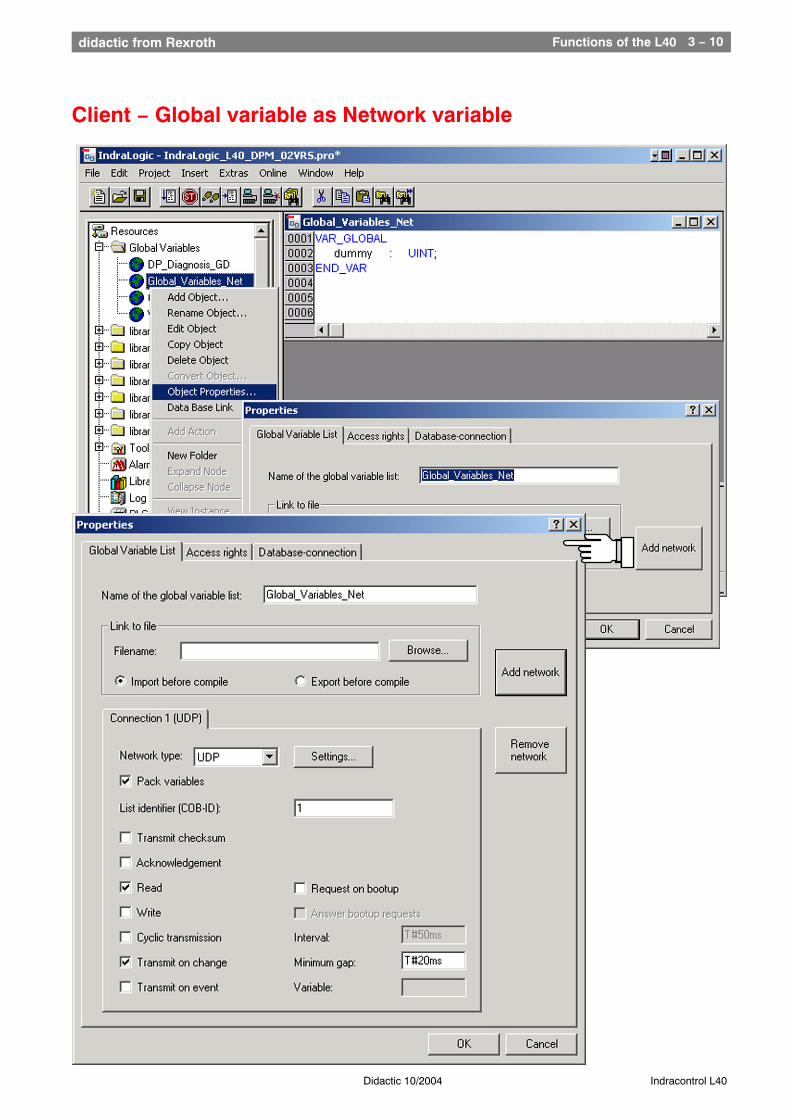
Client − Global variable as Network variable
Functions of the L40 3 − 11didactic from Rexroth
Didactic 10/2004 Indracontrol L40
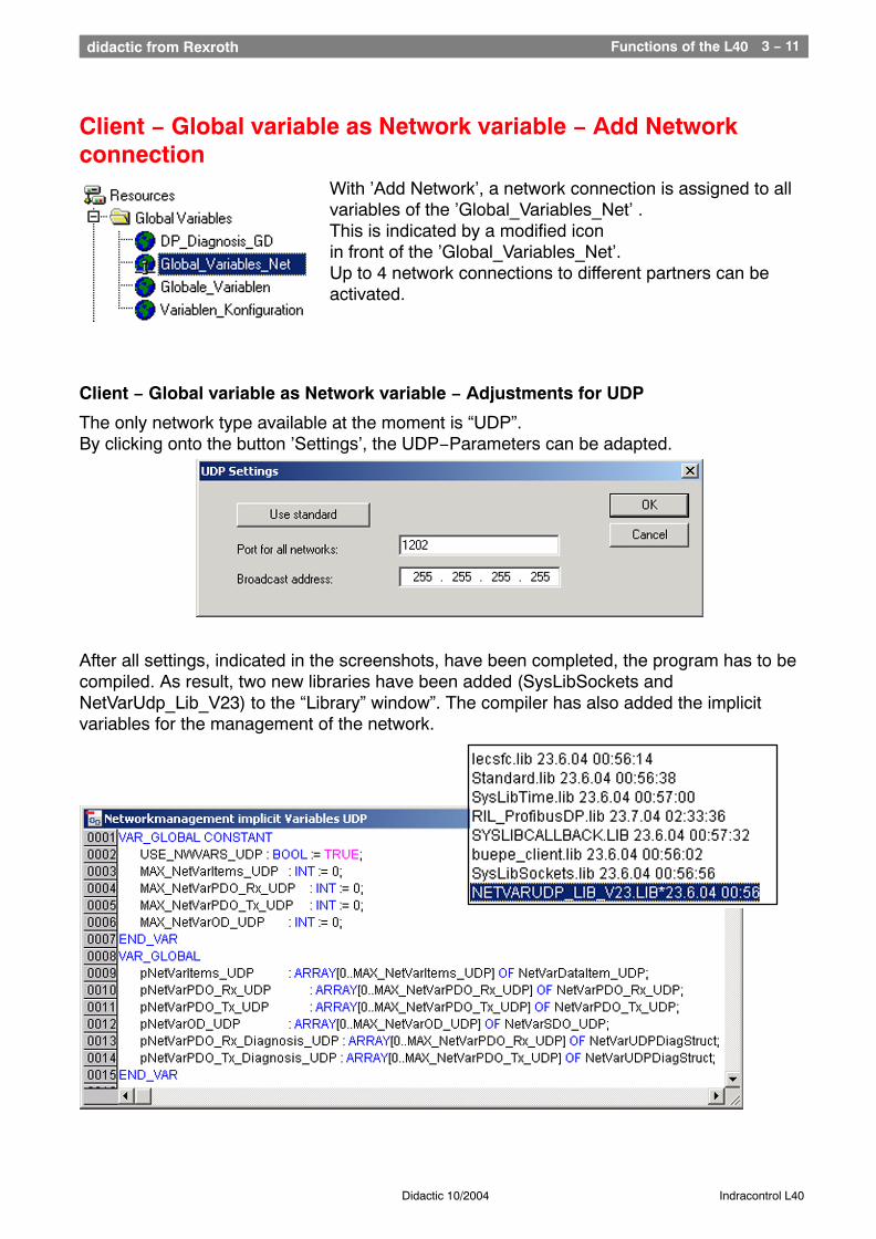
Client − Global variable as Network variable − Add Networkconnection
With ’Add Network’, a network connection is assigned to all variables of the ’Global_Variables_Net’ .This is indicated by a modified icon in front of the ’Global_Variables_Net’. Up to 4 network connections to different partners can beactivated.
Client − Global variable as Network variable − Adjustments for UDP
The only network type available at the moment is “UDP”.By clicking onto the button ’Settings’, the UDP−Parameters can be adapted.
After all settings, indicated in the screenshots, have been completed, the program has to becompiled. As result, two new libraries have been added (SysLibSockets andNetVarUdp_Lib_V23) to the “Library” window”. The compiler has also added the implicitvariables for the management of the network.
Functions of the L40 3 − 12didactic from Rexroth
Didactic 10/2004 Indracontrol L40
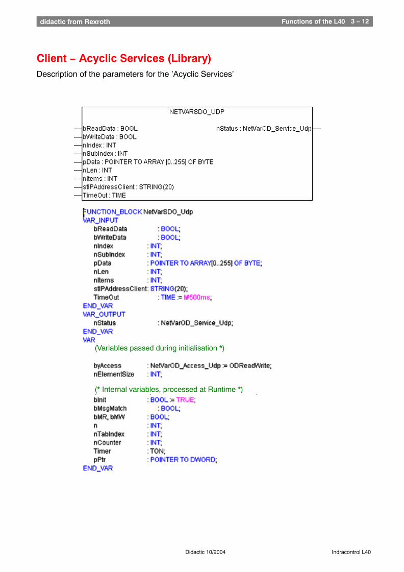
Client − Acyclic Services (Library)Description of the parameters for the ’Acyclic Services’
(Variables passed during initialisation *)
(* Internal variables, processed at Runtime *)
Functions of the L40 3 − 13didactic from Rexroth
Didactic 10/2004 Indracontrol L40
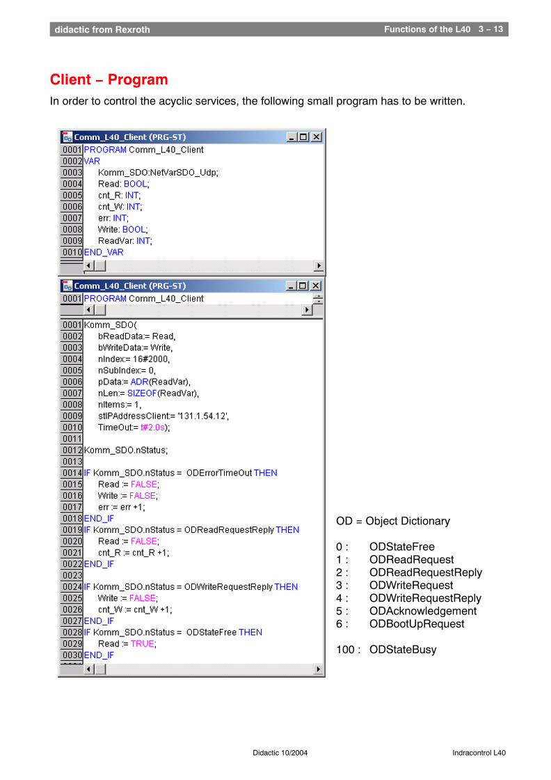
Client − ProgramIn order to control the acyclic services, the following small program has to be written.
OD = Object Dictionary
0 : ODStateFree1 : ODReadRequest2 : ODReadRequestReply3 : ODWriteRequest4 : ODWriteRequestReply5 : ODAcknowledgement6 : ODBootUpRequest
100 : ODStateBusy
Functions of the L40 3 − 14didactic from Rexroth
Didactic 10/2004 Indracontrol L40
Procedures at the Server
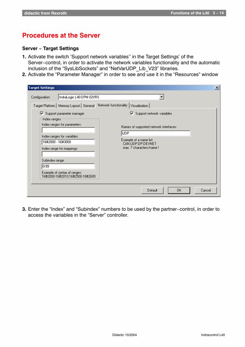
Server − Target Settings
1. Activate the switch ’Support network variables’’ in the Target Settings’ of the Server−control, in order to activate the network variables functionality and the automatic inclusion of the “SysLibSockets” and “NetVarUDP_Lib_V23” libraries.
2. Activate the “Parameter Manager” in order to see and use it in the “Resources” window
3. Enter the “Index” and “Subindex” numbers to be used by the partner−control, in order to access the variables in the “Server” controller.
Functions of the L40 3 − 15didactic from Rexroth
Didactic 10/2004 Indracontrol L40
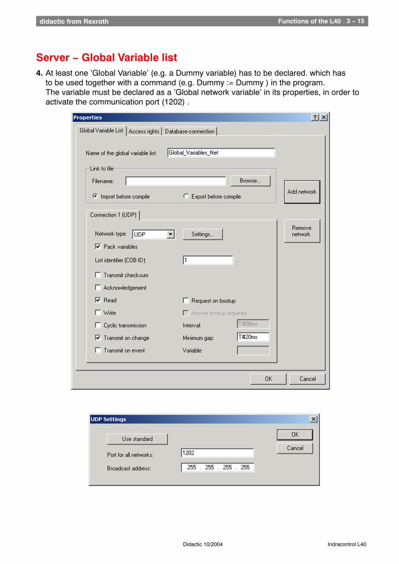
Server − Global Variable list4. At least one ’Global Variable’ (e.g. a Dummy variable) has to be declared. which has
to be used together with a command (e.g. Dummy := Dummy ) in the program.The variable must be declared as a ’Global network variable’ in its properties, in order to activate the communication port (1202) .
Functions of the L40 3 − 16didactic from Rexroth
Didactic 10/2004 Indracontrol L40
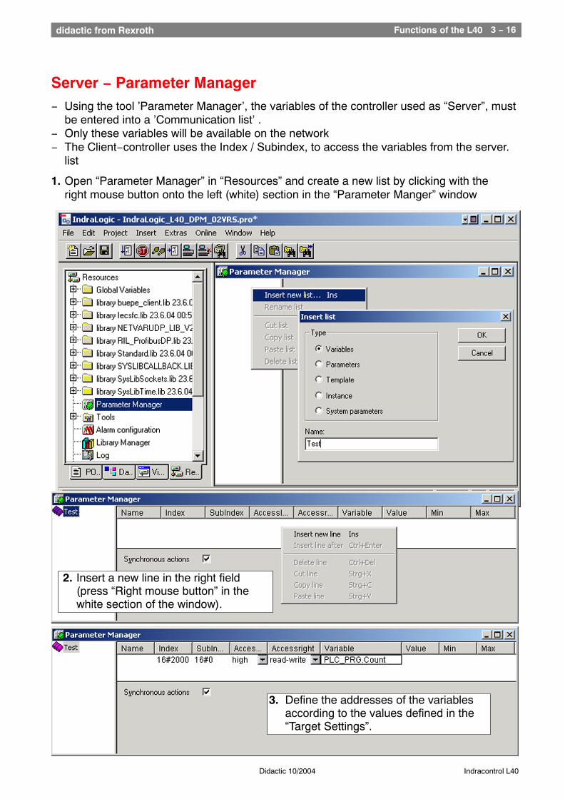
Server − Parameter Manager− Using the tool ’Parameter Manager’, the variables of the controller used as “Server”, must
be entered into a ’Communication list’ .− Only these variables will be available on the network− The Client−controller uses the Index / Subindex, to access the variables from the server.
list
1. Open “Parameter Manager” in “Resources” and create a new list by clicking with the right mouse button onto the left (white) section in the “Parameter Manger” window
3. Define the addresses of the variables according to the values defined in the“Target Settings”.
2. Insert a new line in the right field(press “Right mouse button” in the white section of the window).
Functions of the L40 3 − 17didactic from Rexroth
Didactic 10/2004 Indracontrol L40
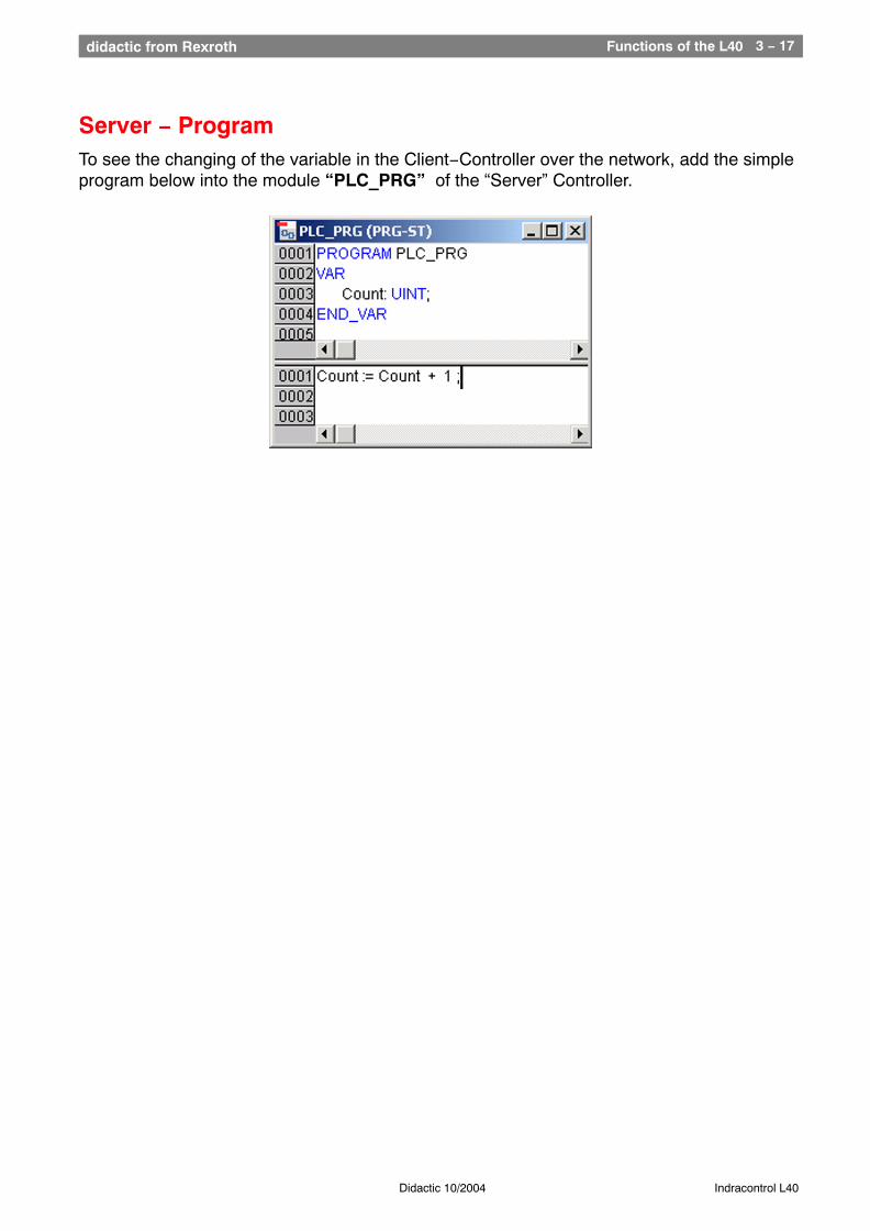
Server − ProgramTo see the changing of the variable in the Client−Controller over the network, add the simpleprogram below into the module “PLC_PRG” of the “Server” Controller.
Functions of the L40 3 − 18didactic from Rexroth
Didactic 10/2004 Indracontrol L40
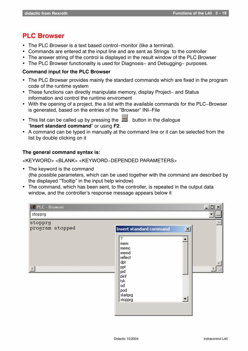
PLC Browser• The PLC Browser is a text based control−monitor (like a terminal).• Commands are entered at the input line and are sent as Strings to the controller• The answer string of the control is displayed in the result window of the PLC Browser• The PLC Browser functionality is used for Diagnosis− and Debugging− purposes.
Command input for the PLC Browser
• The PLC Browser provides mainly the standard commands which are fixed in the programcode of the runtime system
• These functions can directly manipulate memory, display Project− and Status information and control the runtime enviroment
• With the opening of a project, the a list with the available commands for the PLC−Browser is generated, based on the entries of the “Browser” INI−File
• This list can be called up by pressing the button in the dialogue“Insert standard command” or using F2.
• A command can be typed in manually at the command line or it can be selected from the list by double clicking on it
The general command syntax is:
<KEYWORD> <BLANK> <KEYWORD−DEPENDED PARAMETERS>
• The keyword is the command(the possible parameters, which can be used together with the command are described bythe displayed “Tooltip” in the input help window)
• The command, which has been sent, to the controller, is repeated in the output data window, and the controller’s response message appears below it
Functions of the L40 3 − 19didactic from Rexroth
Didactic 10/2004 Indracontrol L40
Usage of macros during the command input in the “PLC−Browser”
If a command associated with a macro is entered in the command line, the command isexpanded before it is sent to the controller. The response message in the result windowappears in a similarly expanded form.
The entry syntax is: <KEYWORD> <Macro>
<KEYWORD> is the command.
Macros are:
%P<NAME> If NAME is a POU−name, the expression is expanded to <POU−Index>,otherwise there is no change
%V<NAME> If NAME is a variable name, the expression is expanded to#<INDEX>:<OFFSET>, otherwise there is no change (this notation#<INDEX>:<OFFSET> is interpreted by the controller as a memoryaddress)
%T<NAME> If NAME is a variable name, the expression is expanded to<VARIABLETYPE>, otherwise there is no change.
%S<NAME> If NAME is a variable name, the expression is expanded to<SIZEOF(VAR)>, otherwise there is no change.
The “ % “ character is ignored if the “Escape” symbol “ \ “ (Backslash) is placed in front.The escape symbol as such is only transmitted if written in the form of “ \\. “
Example: Entry in command line: (memory dump of the variable .testit ?)mem %V.testit
Output in result window: mem #4:5203BAAA24 00 00 00 00 CD CD CD CD ....
Further PLC−Browser optionsIn the ’Extras’ menu or in the “PLC−Browser” toolbar, the following “Operations” areavailable, to handle the command entry or history list:
“History forward” and “History backward”, it is possible to scroll through the queryresults already carried out. The history recording continues until the project is closed.
With the “Cancel”, an initiated “Query” can be stopped
With “Save history list”, the query results carried out until now can be saved into an externaltext file. When selecting this function, the dialogue ’Save file as’ will be displayed.In the dialogue window, the file name with the extension “.bhl” (Browser History List) can beentered.
The command “Print last command” opens the standard print dialogue, and the current queryplus the output data in the message window can be printed.
Functions of the L40 3 − 20didactic from Rexroth
Didactic 10/2004 Indracontrol L40
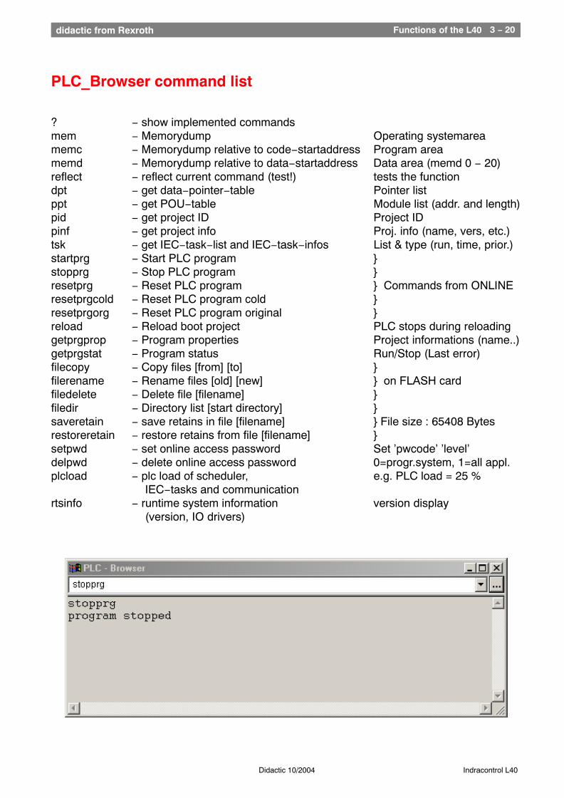
PLC_Browser command list
? − show implemented commandsmem − Memorydump Operating systemareamemc − Memorydump relative to code−startaddress Program areamemd − Memorydump relative to data−startaddress Data area (memd 0 − 20)reflect − reflect current command (test!) tests the functiondpt − get data−pointer−table Pointer listppt − get POU−table Module list (addr. and length)pid − get project ID Project IDpinf − get project info Proj. info (name, vers, etc.)tsk − get IEC−task−list and IEC−task−infos List & type (run, time, prior.)startprg − Start PLC program }stopprg − Stop PLC program }resetprg − Reset PLC program } Commands from ONLINEresetprgcold − Reset PLC program cold }resetprgorg − Reset PLC program original }reload − Reload boot project PLC stops during reloadinggetprgprop − Program properties Project informations (name..)getprgstat − Program status Run/Stop (Last error)filecopy − Copy files [from] [to] }filerename − Rename files [old] [new] } on FLASH cardfiledelete − Delete file [filename] }filedir − Directory list [start directory] }saveretain − save retains in file [filename] } File size : 65408 Bytesrestoreretain − restore retains from file [filename] }setpwd − set online access password Set ’pwcode’ ’level’delpwd − delete online access password 0=progr.system, 1=all appl.plcload − plc load of scheduler, e.g. PLC load = 25 %
IEC−tasks and communicationrtsinfo − runtime system information version display
(version, IO drivers)
Functions of the L40 3 − 21didactic from Rexroth
Didactic 10/2004 Indracontrol L40
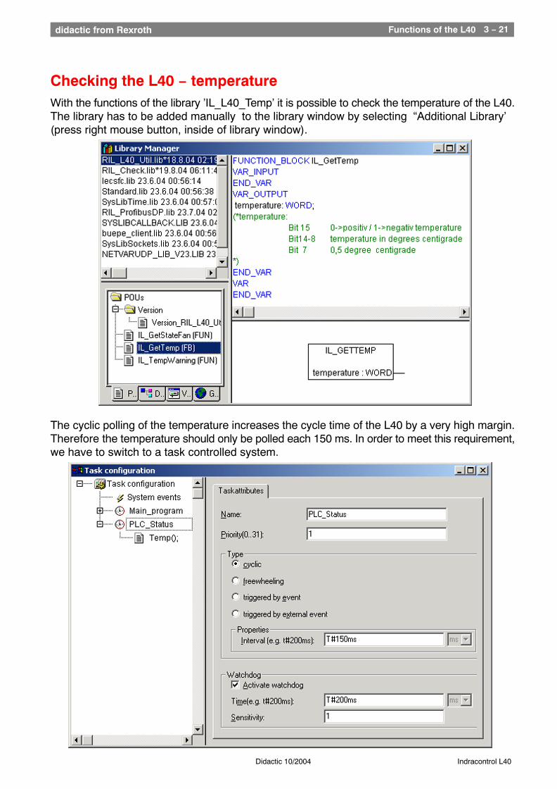
Checking the L40 − temperatureWith the functions of the library ’IL_L40_Temp’ it is possible to check the temperature of the L40.The library has to be added manually to the library window by selecting “Additional Library’(press right mouse button, inside of library window).
The cyclic polling of the temperature increases the cycle time of the L40 by a very high margin.Therefore the temperature should only be polled each 150 ms. In order to meet this requirement,we have to switch to a task controlled system.
Functions of the L40 3 − 22didactic from Rexroth
Didactic 10/2004 Indracontrol L40
Task
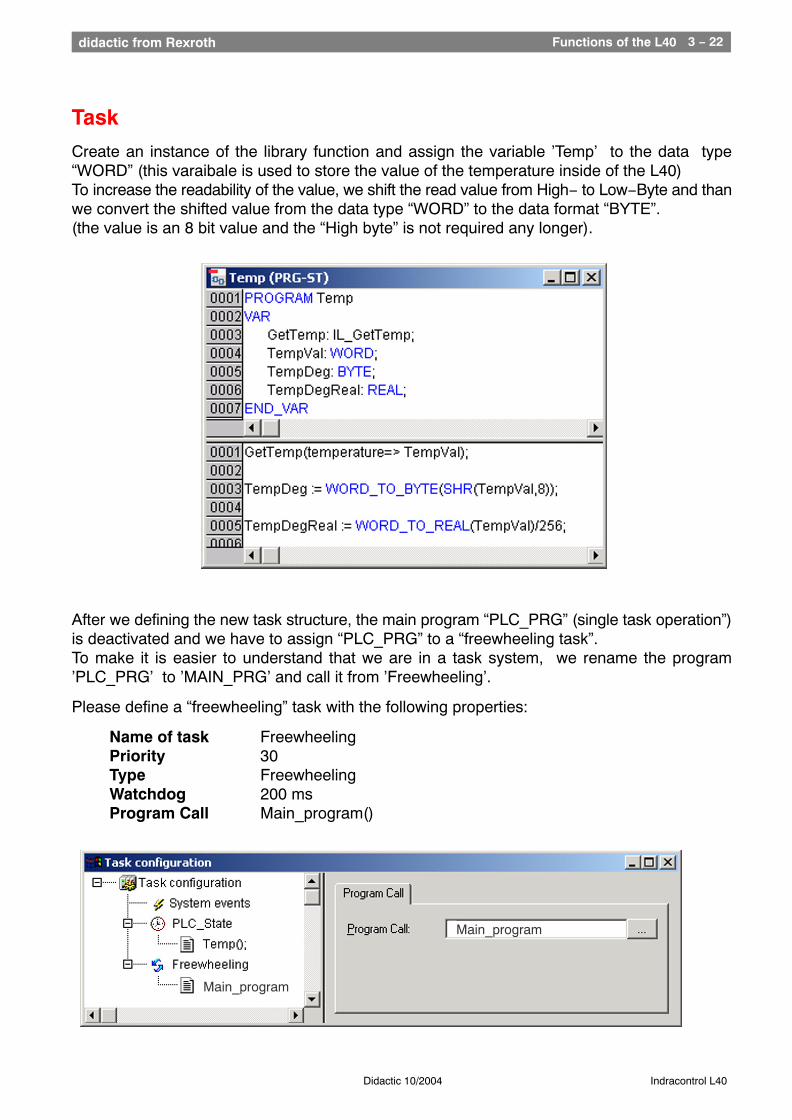
Create an instance of the library function and assign the variable ’Temp’ to the data type“WORD” (this varaibale is used to store the value of the temperature inside of the L40)To increase the readability of the value, we shift the read value from High− to Low−Byte and thanwe convert the shifted value from the data type “WORD” to the data format “BYTE”.(the value is an 8 bit value and the “High byte” is not required any longer).
After we defining the new task structure, the main program “PLC_PRG” (single task operation”)is deactivated and we have to assign “PLC_PRG” to a “freewheeling task”.To make it is easier to understand that we are in a task system, we rename the program’PLC_PRG’ to ’MAIN_PRG’ and call it from ’Freewheeling’.
Please define a “freewheeling” task with the following properties:
Name of task FreewheelingPriority 30Type FreewheelingWatchdog 200 msProgram Call Main_program()
Main_program
Main_program
Exercises 3 − 23didactic from Rexroth
Didactic 10/2004 Indracontrol L40
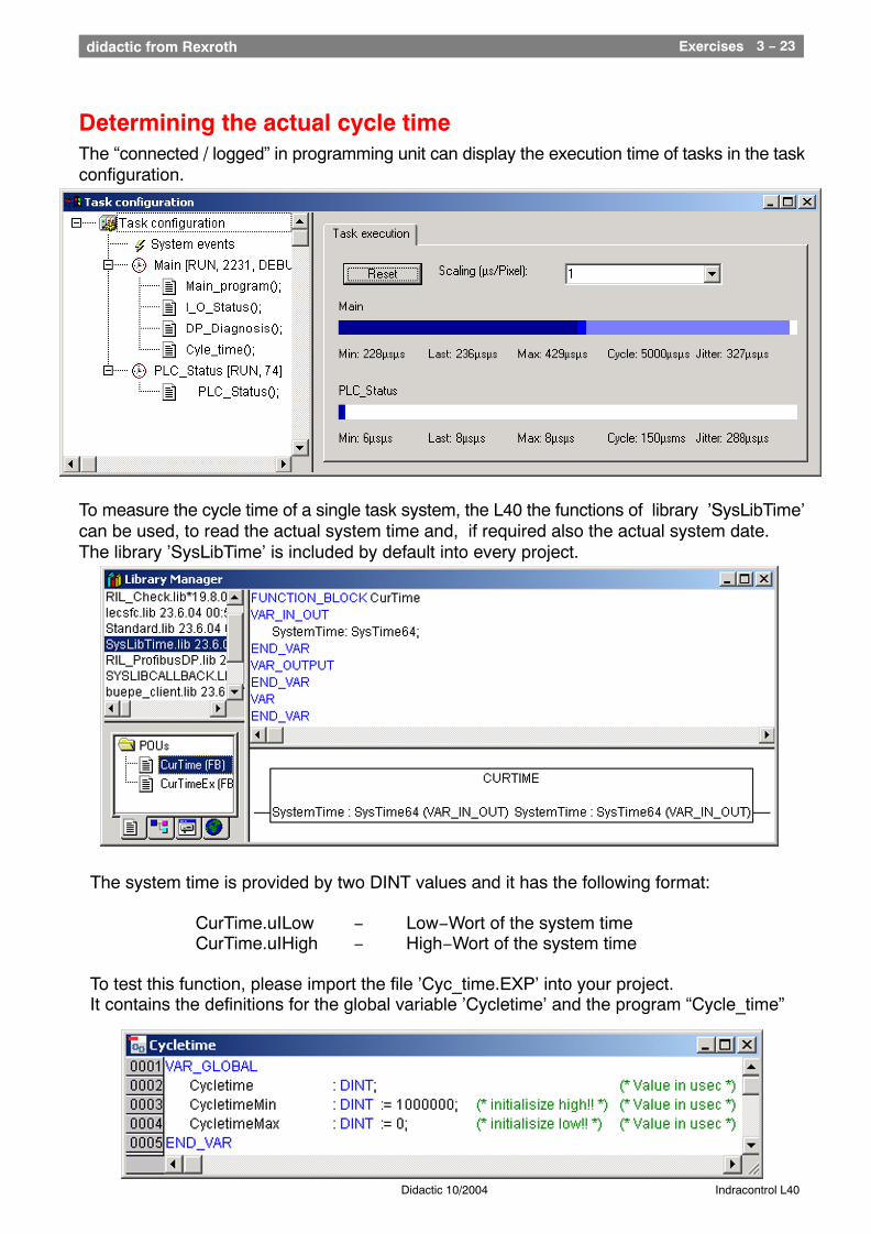
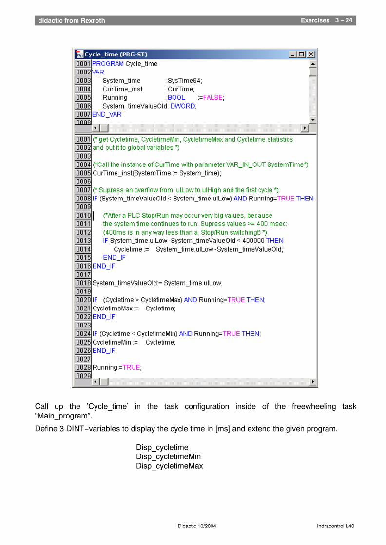
Determining the actual cycle timeThe “connected / logged” in programming unit can display the execution time of tasks in the taskconfiguration.
To measure the cycle time of a single task system, the L40 the functions of library ’SysLibTime’can be used, to read the actual system time and, if required also the actual system date.The library ’SysLibTime’ is included by default into every project.
The system time is provided by two DINT values and it has the following format:
CurTime.uILow − Low−Wort of the system timeCurTime.uIHigh − High−Wort of the system time
To test this function, please import the file ’Cyc_time.EXP’ into your project.It contains the definitions for the global variable ’Cycletime’ and the program “Cycle_time”
Exercises 3 − 24didactic from Rexroth
Didactic 10/2004 Indracontrol L40
Call up the ’Cycle_time’ in the task configuration inside of the freewheeling task“Main_program”.
Define 3 DINT−variables to display the cycle time in [ms] and extend the given program.
Disp_cycletimeDisp_cycletimeMinDisp_cycletimeMax
Functions of the L40 3 − 25didactic from Rexroth
Didactic 10/2004 Indracontrol L40
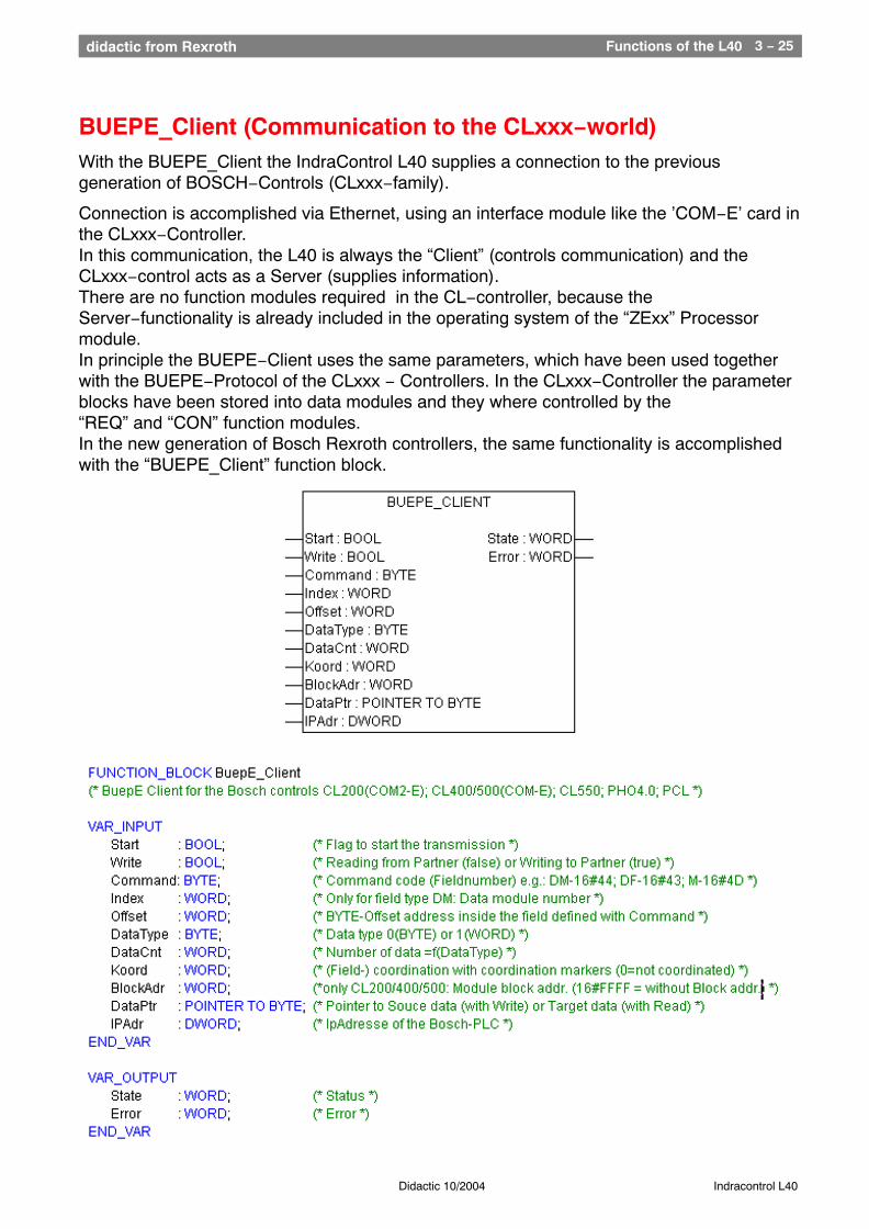
BUEPE_Client (Communication to the CLxxx−world)With the BUEPE_Client the IndraControl L40 supplies a connection to the previousgeneration of BOSCH−Controls (CLxxx−family).
Connection is accomplished via Ethernet, using an interface module like the ’COM−E’ card inthe CLxxx−Controller. In this communication, the L40 is always the “Client” (controls communication) and theCLxxx−control acts as a Server (supplies information).There are no function modules required in the CL−controller, because theServer−functionality is already included in the operating system of the “ZExx” Processormodule.In principle the BUEPE−Client uses the same parameters, which have been used togetherwith the BUEPE−Protocol of the CLxxx − Controllers. In the CLxxx−Controller the parameterblocks have been stored into data modules and they where controlled by the“REQ” and “CON” function modules.In the new generation of Bosch Rexroth controllers, the same functionality is accomplishedwith the “BUEPE_Client” function block.
Functions of the L40 3 − 26didactic from Rexroth
Didactic 10/2004 Indracontrol L40
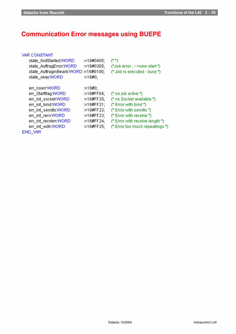
Communication Error messages using BUEPE
Functions of the L40 3 − 27didactic from Rexroth
Didactic 10/2004 Indracontrol L40
Communication between a L40 and a CL200
Program in the L40
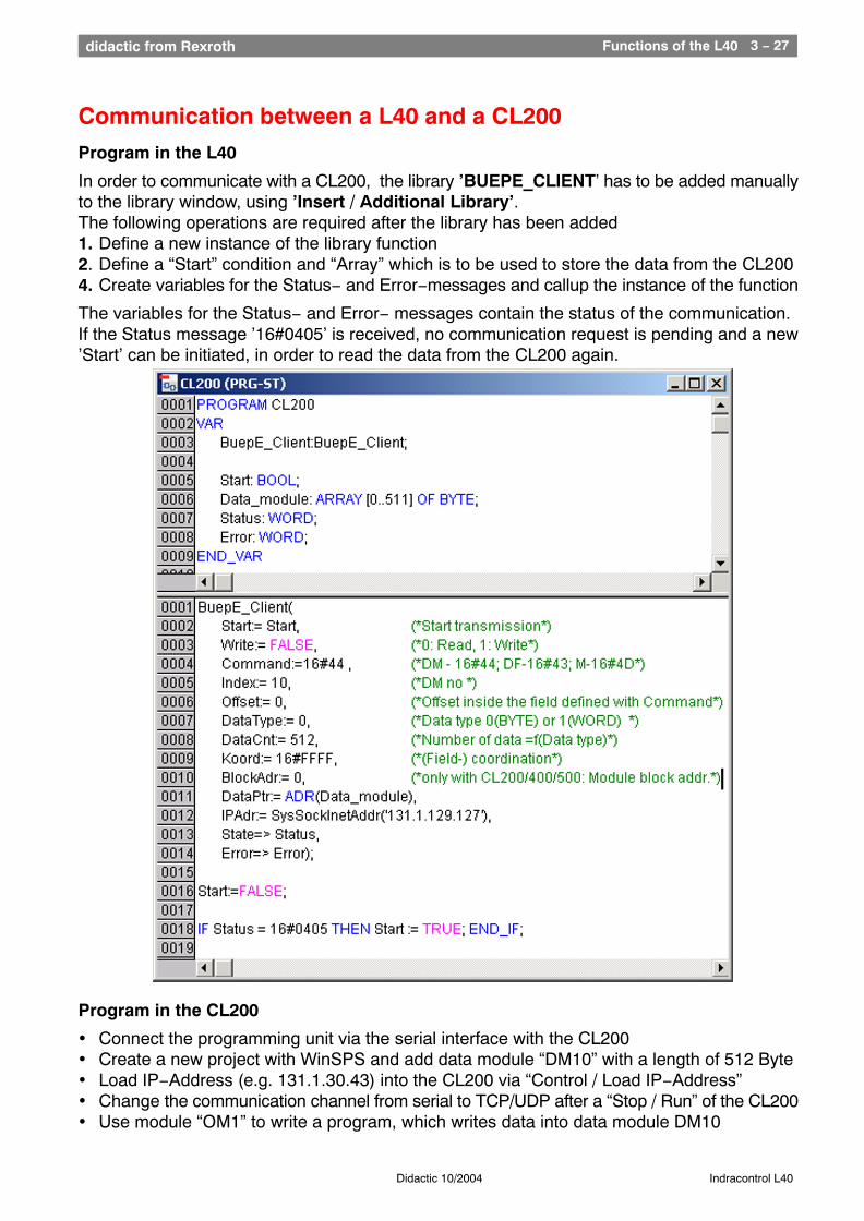
In order to communicate with a CL200, the library ’BUEPE_CLIENT’ has to be added manuallyto the library window, using ’Insert / Additional Library’. The following operations are required after the library has been added1. Define a new instance of the library function2. Define a “Start” condition and “Array” which is to be used to store the data from the CL2004. Create variables for the Status− and Error−messages and callup the instance of the function
The variables for the Status− and Error− messages contain the status of the communication.If the Status message ’16#0405’ is received, no communication request is pending and a new’Start’ can be initiated, in order to read the data from the CL200 again.
Program in the CL200
• Connect the programming unit via the serial interface with the CL200• Create a new project with WinSPS and add data module “DM10” with a length of 512 Byte• Load IP−Address (e.g. 131.1.30.43) into the CL200 via “Control / Load IP−Address” • Change the communication channel from serial to TCP/UDP after a “Stop / Run” of the CL200• Use module “OM1” to write a program, which writes data into data module DM10
Functions of the L40 3 − 28didactic from Rexroth
Didactic 10/2004 Indracontrol L40
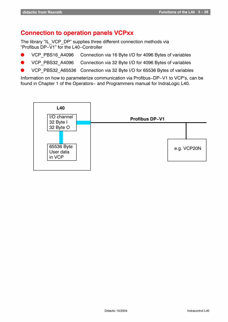
Connection to operation panels VCPxxThe library “IL_VCP_DP” supplies three different connection methods via“Profibus DP−V1” for the L40−Controller
l VCP_PBS16_A4096 Connection via 16 Byte I/O for 4096 Bytes of variables
l VCP_PBS32_A4096 Connection via 32 Byte I/O for 4096 Bytes of variables
l VCP_PBS32_A65536 Connection via 32 Byte I/O for 65536 Bytes of variables
Information on how to parameterize communication via Profibus−DP−V1 to VCP’s, can befound in Chapter 1 of the Operators− and Programmers manual for IndraLogic L40.
e.g. VCP20N
Profibus DP−V1
65536 ByteUser data in VCP
L40
I/O channel32 Byte I32 Byte O
Functions of the L40 3 − 29didactic from Rexroth
Didactic 10/2004 Indracontrol L40
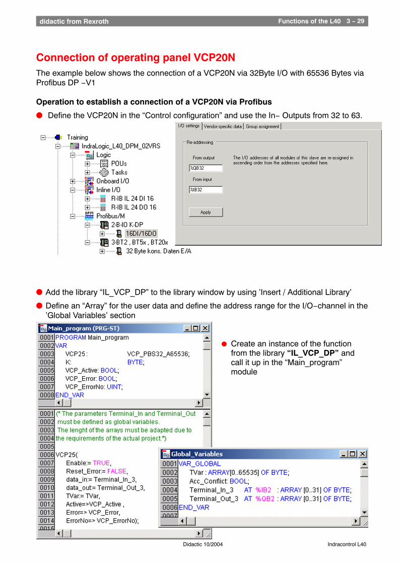
Connection of operating panel VCP20NThe example below shows the connection of a VCP20N via 32Byte I/O with 65536 Bytes viaProfibus DP −V1
Operation to establish a connection of a VCP20N via Profibus
l Define the VCP20N in the “Control configuration” and use the In− Outputs from 32 to 63.
l Add the library “IL_VCP_DP” to the library window by using ’Insert / Additional Library’
l Define an “Array” for the user data and define the address range for the I/O−channel in the’Global Variables’ section
l Create an instance of the functionfrom the library “IL_VCP_DP” andcall it up in the “Main_program”module
Functions of the L40 3 − 30didactic from Rexroth
Didactic 10/2004 Indracontrol L40
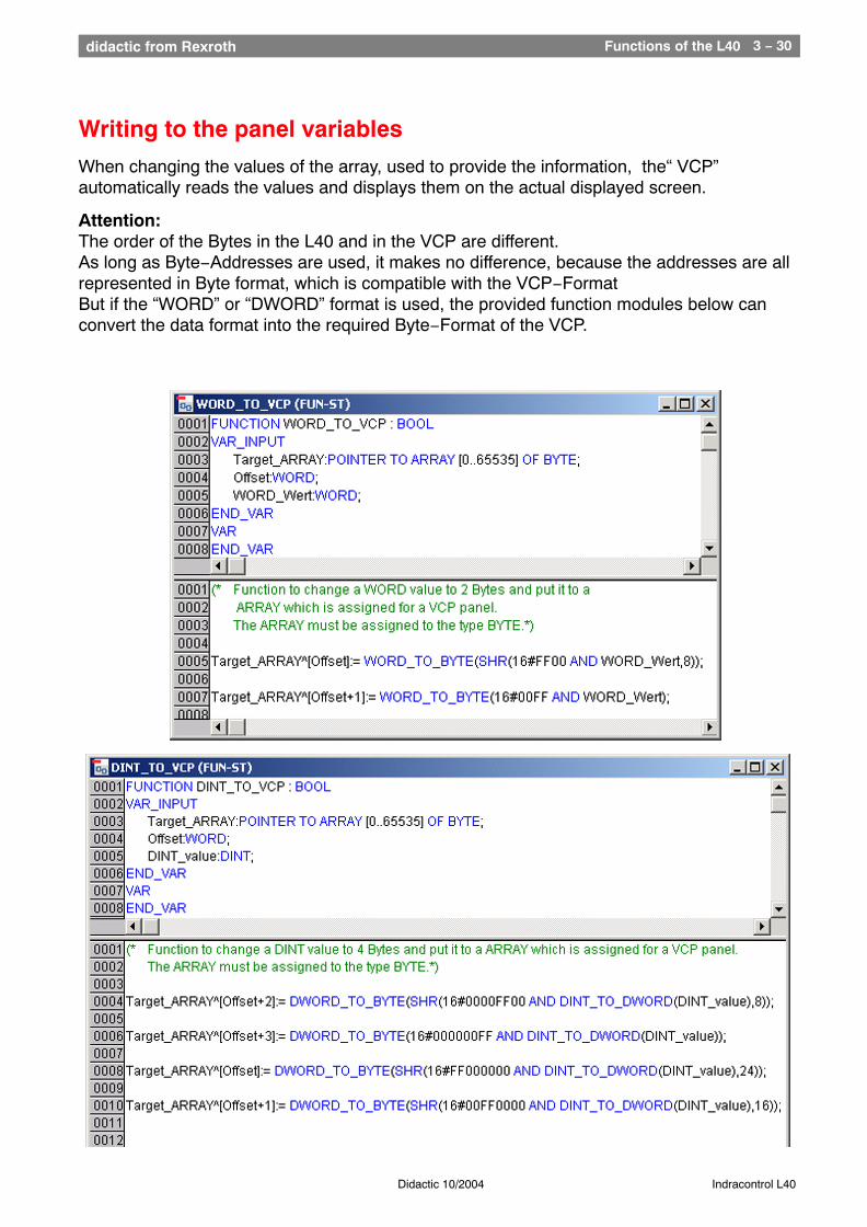
Writing to the panel variables
When changing the values of the array, used to provide the information, the“ VCP”automatically reads the values and displays them on the actual displayed screen.
Attention: The order of the Bytes in the L40 and in the VCP are different. As long as Byte−Addresses are used, it makes no difference, because the addresses are allrepresented in Byte format, which is compatible with the VCP−FormatBut if the “WORD” or “DWORD” format is used, the provided function modules below canconvert the data format into the required Byte−Format of the VCP.
Functions of the L40 3 − 31didactic from Rexroth
Didactic 10/2004 Indracontrol L40
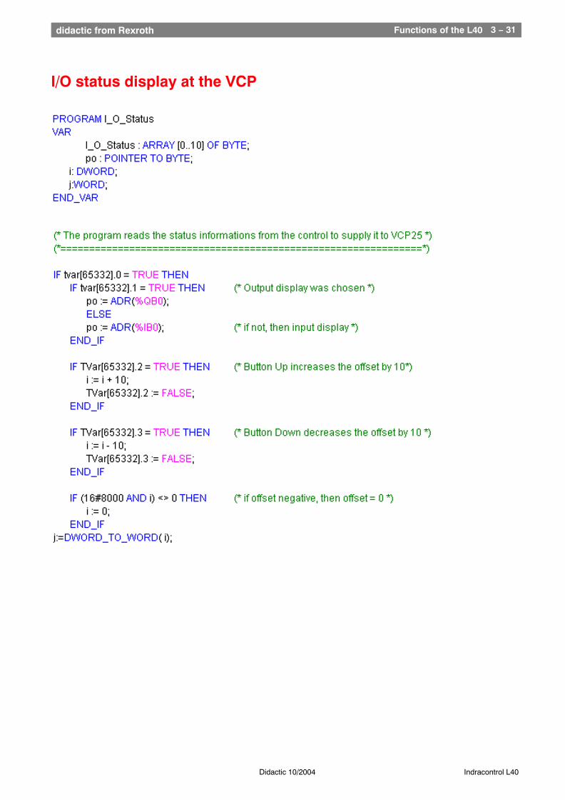
I/O status display at the VCP
Functions of the L40 3 − 32didactic from Rexroth
Didactic 10/2004 Indracontrol L40
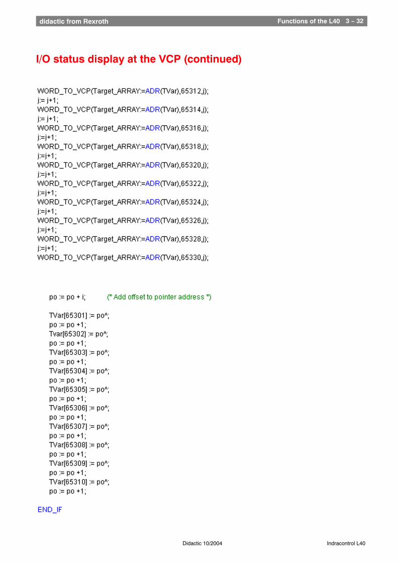
I/O status display at the VCP (continued)
Functions of the L40 3 − 33didactic from Rexroth
Didactic 10/2004 Indracontrol L40
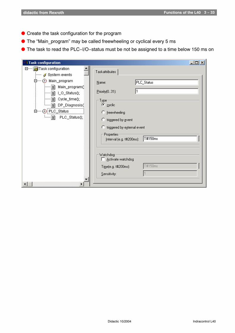
l Create the task configuration for the program
l The “Main_program” may be called freewheeling or cyclical every 5 ms
l The task to read the PLC−I/O−status must be not be assigned to a time below 150 ms on