Embed Size (px)
Citation preview

ND DEPT OF TRANSPORTATION SURVEYS & PHOTOGRAMMETRY DATE: DECEMBER, 2006 REVISED:
2/22/2007
TRAINING MANUAL
FOR
Online Positioning User Service (OPUS)
NOTE: This manual provides a written account of how certain activities are performed and is designed to guide and assist staff members in performing their functions. When appropriate, there may be deviations from these written procedures due to changes in personnel, policies, interpretation, law, experimentation with different systems, or simply evolution of the process itself. This manual may be changed at any time. Staff members are encouraged to review this manual periodically and suggest changes in the manual to keep the manual current and to minimize differences between the manual and actual practices.

Prepared by
NORTH DAKOTA DEPARTMENT OF TRANSPORTATION
BISMARCK, NORTH DAKOTA www.dot.nd.gov
DIRECTOR Francis G. Ziegler, P. E.
Design Division
Mark Gaydos, P.E.

ND DEPT OF TRANSPORTATION SURVEYS & PHOTOGRAMMETRY TRAINING SUBJECT: OPUS/CORS CONTROL
2/22/2007
INDEX
CONTENTS PAGE What is OPUS (NOAA) 1-2 Planning and Almanac 3-18 NDDOT OPUS Survey Style 19-24 Project Control (Chapter 19-1.1 to 19-1.3) 25-27 CORS Stations 28-38 Using OPUS – OPUS Guidelines 39-48 OPUS Discussion 49-52 Reviewing Solutions – with examples 52-54 Additional Notes 55

ND DEPT OF TRANSPORTATION SURVEYS & PHOTOGRAMMETRY TRAINING SUBJECT: OPUS/CORS CONTROL
2/22/2007 1 of 54
Online Positioning User Service
What is OPUS? The National Geodetic Survey operates the On-line Positioning User Service (OPUS) as a means to provide GPS users easier access to the National Spatial Reference System (NSRS).
OPUS allows users to submit their GPS data files to NGS, where the data will be processed to determine a position using NGS computers and software. Each data file that is submitted will be processed with respect to 3 CORS sites. The sites selected may not be the nearest to your site but are selected by distance, # of obs, site stability, etc. The position for your data will be reported back to you via email in both ITRF and NAD83 coordinates as well as UTM, USNG and State Plane Coordinates (SPC) northing and easting.
OPUS is completely automatic and requires only a minimal amount of information from the user:
1. The email address where you want the results sent 2. The data file that you want to process (which you may select using the browse
feature) 3. The antenna type used to collect this data file (selected from a list of calibrated
GPS antennas) 4. The height of the Antenna Reference Point (ARP) above the monument or mark
that you are positioning 5. As an option, you may also enter the state plane coordinate code if you want
SPC northing and easting. 6. As an option, you may select up to 3 base stations to be used in determining
your solution.
ND DEPT OF TRANSPORTATION SURVEYS & PHOTOGRAMMETRY TRAINING SUBJECT: OPUS/CORS CONTROL
2 of 54 2/22/2007
Once this information is complete, you then click the Upload button to send your data to NGS. Your results will be emailed to you, usually within a few minutes. You may upload multiple data files in a zip archive if you wish. However, be careful, the options that you choose will be applied to all of the data files in that archive (i.e. The same antenna type, ARP height will be used for all of the files in the zip file).
Please read through each of the OPUS Help Links. It is important that you understand how to correctly submit your data and how to interpret your results. An OPUS email button is provided for any inquiries or comments that you may have.
In spite of our efforts to test OPUS as thoroughly as practical, new problems will almost certainly occur. Please contact OPUS with any problems you believe you see and they will be addressed as quickly as possible.
OPUS is intended for use in the conterminous U.S. and most territories. It is NGS policy to not publish geodetic coordinates outside the U.S. without the agreement of the affected countries.
National Geodetic Survey - OPUS Team Last modified: January 7, 2004 http://www.ngs.noaa.gov/OPUS/What_is_OPUS.html

ND DEPT OF TRANSPORTATION SURVEYS & PHOTOGRAMMETRY TRAINING SUBJECT: OPUS/CORS CONTROL
2/22/2007 3 of 54
Planning and Almanac Planning is a helpful tool to schedule your OPUS sessions and give you estimated times that may not be beneficial to collect data. Satellite availability is much better than it used to be when signals were restricted to only a few hours a day, but planning is still a key part in monitoring your survey schedule. Planning answers the following questions:
• When are the DOP spikes for a specified location and time. • When are the best conditions for logging data. • How many satellites will there be for a specified location and time.
The only file that you will need for these outlined questions is the almanac file that you need to download. You can view and print your answers to these questions in either graphs or tables as will be outlined below. The planning tools are located in sub-menus and some tools are also located on the button bars.
The following sub-menus are available:
Planning Pull-down Menus
File Allows you to create and manipulate stations or multistations. Station data includes the position on earth, possible obstructions, general cutoff elevation angle and a maximum time span. For simultaneous observation of at least two stations you may create or manipulate a multistation network. You may also print the graphs or terminate Planning from here.
Almanac Allows you to choose and load almanac data from different receiver types, to inspect its values and to save or delete it.
Satellites Individual satellites may be enabled or disabled. Detailed information for all tracked satellites is available.

ND DEPT OF TRANSPORTATION SURVEYS & PHOTOGRAMMETRY TRAINING SUBJECT: OPUS/CORS CONTROL
4 of 54 2/22/2007
Graphs Lets you create one of the already available, preprogrammed graphs.
Lists Shows results in form of printable lists.
Options Lets you toggle the legend/agenda and lets you determine which satellite systems are available. These include GPS, GLONASS, IGSO and geostationary satellites.
Windows Offers the typical MS Windows options regarding window handling and allows you to toggle the toolbar.
Help Provides information on the current version and offers help.
A toolbar offers quick and intuitive access to most of Planning’s options.
Planning Toolbar
Allows you to select station location
Multistation analysis
Clear almanac for new
Open almanac files
Save almanac
Satellite selection

ND DEPT OF TRANSPORTATION SURVEYS & PHOTOGRAMMETRY TRAINING SUBJECT: OPUS/CORS CONTROL
2/22/2007 5 of 54
Satellite information
Elevation graph
Number of satellites graph
Satellite sky plot
Satellite visibility table
DOP graph
World projection map
Turns graph and table almanac information (Agenda) on and off
Turns table and graph legend on and off
Prints tables and graphs
Help

ND DEPT OF TRANSPORTATION SURVEYS & PHOTOGRAMMETRY TRAINING SUBJECT: OPUS/CORS CONTROL
6 of 54 2/22/2007
Review of the current Planning Almanac shall be done prior to running a logging session for OPUS. Logging sessions should not be run during spikes in PDOP. These times are only estimated and if a session is run during a spike make sure not to begin or end on a spike. If run during a spike you must then run longer than the required 4 hour session and at least 30 minutes after the end of a spike. Following are the instructions on how to update and view your almanac in TGO. Step 1: From the Trimble website download the updated SSF file.
http://www.trimble.com/gpsdataresources.shtml Step 2: Save this file under C:\Program Files\Common Files\Trimble\Planning. Step 3: Open TGO. From the Utilities pull down menu select Planning.

ND DEPT OF TRANSPORTATION SURVEYS & PHOTOGRAMMETRY TRAINING SUBJECT: OPUS/CORS CONTROL
2/22/2007 7 of 54
Step 4: From the Almanac pull down menu select Import then SSF…

ND DEPT OF TRANSPORTATION SURVEYS & PHOTOGRAMMETRY TRAINING SUBJECT: OPUS/CORS CONTROL
8 of 54 2/22/2007
Step 5: Select current.ssf file from C:\Program Files\Common Files\Trimble\Planning previously
saved from the Trimble website.
This ends the update process.

ND DEPT OF TRANSPORTATION SURVEYS & PHOTOGRAMMETRY TRAINING SUBJECT: OPUS/CORS CONTROL
2/22/2007 9 of 54
Edit Station
Following are the instruction on how to select or edit your station location. You may define new stations and determine their coordinates and cutoff elevation angle. You can determine sky visibility with obstructions. At the same time, you can define the time segment for the visibility analysis.
You may choose your station by using coordinates that you occupied previously, by city, and by selecting a location on the map. During this portion you will also be able to set up your time information, duration, and interval along with selecting your time zone.
Step 1: Select the File pull down menu then Station… or

ND DEPT OF TRANSPORTATION SURVEYS & PHOTOGRAMMETRY TRAINING SUBJECT: OPUS/CORS CONTROL
10 of 54 2/22/2007
Step 2: The following window will appear.
Select the City or Map buttons to choose your station location as shown on the following pages.

ND DEPT OF TRANSPORTATION SURVEYS & PHOTOGRAMMETRY TRAINING SUBJECT: OPUS/CORS CONTROL
2/22/2007 11 of 54
The City window will appear as follows and select the city you desire for your location.
Define Coordinates - Select City
The map window will appear as follows. Click Select to select the city and its horizontal coordinates, click Cancel to leave the dialog without any changes to the Station Editor.
Define Coordinates - World Map

ND DEPT OF TRANSPORTATION SURVEYS & PHOTOGRAMMETRY TRAINING SUBJECT: OPUS/CORS CONTROL
12 of 54 2/22/2007
When you activate a new city name, the corresponding coordinates will be displayed.
The Position block below the station name defines the station position in longitude, latitude and height. You may enter a cutoff elevation. Planning considers no satellites with an elevation below this angle. This value should be set at 13 degrees.
The box Time Information allows you to enter the start date and time. The button Today allows fast entry of today’s date. Define the duration of analysis (Duration) and choose the time interval for calculation (Interval). You may select the date format via the browser button. It is good practice, to have an interval of about 10 min to inspect a whole day.
The box Time Zone displays the currently selected time zone, the current offset to GMT (Greenwich Mean Time) in hours (Difference GME[), and, if any, the Daylight Saving Time (DST). If you want to change the time zone click the button Time Zone.
After completing all fields listed above select OK

ND DEPT OF TRANSPORTATION SURVEYS & PHOTOGRAMMETRY TRAINING SUBJECT: OPUS/CORS CONTROL
2/22/2007 13 of 54
Time Zone Selection
Step 3: Select the Satellites pull down menu then Selection… or

ND DEPT OF TRANSPORTATION SURVEYS & PHOTOGRAMMETRY TRAINING SUBJECT: OPUS/CORS CONTROL
14 of 54 2/22/2007
The following window will appear:
Select all the GPS satellites and turn off all Glonass and WASS satellites. Make sure to click apply for each tab. At this time NDDOT is not using Glonass. WAAS satellites should not be used during this process or for RTK. WAAS is primarily for navigation purposes only.

ND DEPT OF TRANSPORTATION SURVEYS & PHOTOGRAMMETRY TRAINING SUBJECT: OPUS/CORS CONTROL
2/22/2007 15 of 54
Graphics
Each graph may have a legend and an agenda.
The legend lists the objects used for calculation of the graph. You may enable/disable the display of the legend via the pull-down menu option Windows/Legend. The legend may be a satellite legend, assigning colors to each satellite. For the graphs of combined DOP values the legend assigns colors to the DOP types.
Satellite Legend and DOP Legend
The bottom of each graph display is occupied by a summary of the current station’s parameters, the agenda. You may enable/disable the display of the legend via the pull-down menu option Windows/Agenda.
Agenda

ND DEPT OF TRANSPORTATION SURVEYS & PHOTOGRAMMETRY TRAINING SUBJECT: OPUS/CORS CONTROL
16 of 54 2/22/2007
Number of Satellites
The graph Visibility is accessible via the menu function Graphs/Number of Satellites or the corresponding toolbar button.

ND DEPT OF TRANSPORTATION SURVEYS & PHOTOGRAMMETRY TRAINING SUBJECT: OPUS/CORS CONTROL
2/22/2007 17 of 54
Dilution of Precision
Via the menu option Graphs/DOP’s planning offers you several graphs to display several DOP values. The plots may display the DOPS types separately or in combination.

ND DEPT OF TRANSPORTATION SURVEYS & PHOTOGRAMMETRY TRAINING SUBJECT: OPUS/CORS CONTROL
18 of 54 2/22/2007
An important factor in assessing the accuracy of a GPS survey is the geometrical constellation of the satellites that are used during the processing measurement. The Dilution of Precision - or DOP - values are calculated and displayed as functions of time.
The DOP types available are: GDOP: geometrical DOP PDOP: position DOP VDOP: vertical DOP HDOP: horizontal DOP TDOP: temporal DOP
You may choose each of the DOP types separately. If you choose the option All Together or the respective toolbar button, all results will be shown in one single graph, printed one above the other.
Typically, the values follow the following rule:
GDOP > PDOP> (VDOP , HDOP) > TDOP
and, therefore, GDOP values are printed in the background, while TDOP values are shown in front.
An alternative option is to choose All together (Lines) ,which shows the DOP values as lines instead of colored areas. This is located in Graphs/DOP/All Together (lines).
If you choose the option Open 5 DOPs, the plots of the 5 single DOP types will be opened in descending order. You may arrange them on your desktop to compare the values.
NOTE: The presence of obstructions significantly reduces visibility and, therefore, increases the DOP values.
ND DEPT OF TRANSPORTATION SURVEYS & PHOTOGRAMMETRY TRAINING SUBJECT: OPUS/CORS CONTROL
2/22/2007 19 of 54
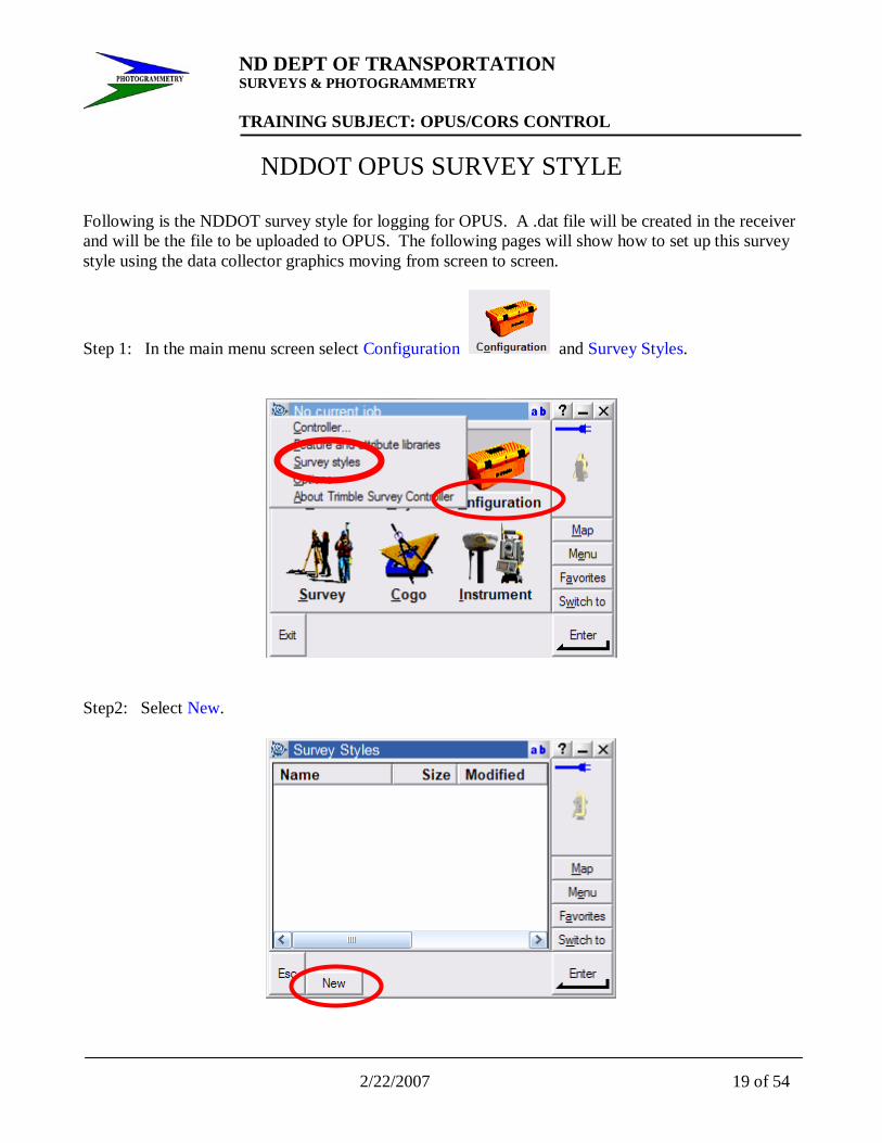
NDDOT OPUS SURVEY STYLE Following is the NDDOT survey style for logging for OPUS. A .dat file will be created in the receiver and will be the file to be uploaded to OPUS. The following pages will show how to set up this survey style using the data collector graphics moving from screen to screen.
Step 1: In the main menu screen select Configuration and Survey Styles.
Step2: Select New.

ND DEPT OF TRANSPORTATION SURVEYS & PHOTOGRAMMETRY TRAINING SUBJECT: OPUS/CORS CONTROL
20 of 54 2/22/2007
Step 3: Enter name, NDDOT OPUS and select GPS for the Style type then Accept.
Step 4: Select Base options and Edit. This is the only portion that needs to be set up for logging.

ND DEPT OF TRANSPORTATION SURVEYS & PHOTOGRAMMETRY TRAINING SUBJECT: OPUS/CORS CONTROL
2/22/2007 21 of 54
Step 5: Touch the Survey type pull down menu and select RTK & logging.
Step 6: Screen 1/3 shall be entered as shown with some selections being located in the pull down menus. Broadcast format: leave as default CMR+, do not select Output additional code RTCM, Station index: leave as default, Logging device shall be set to Receiver, Logging interval: 5.0 seconds, and Elevation mask shall be set to 13°00’00”.
Then touch the 1/3 button to move to next screen.
ND DEPT OF TRANSPORTATION SURVEYS & PHOTOGRAMMETRY TRAINING SUBJECT: OPUS/CORS CONTROL
22 of 54 2/22/2007
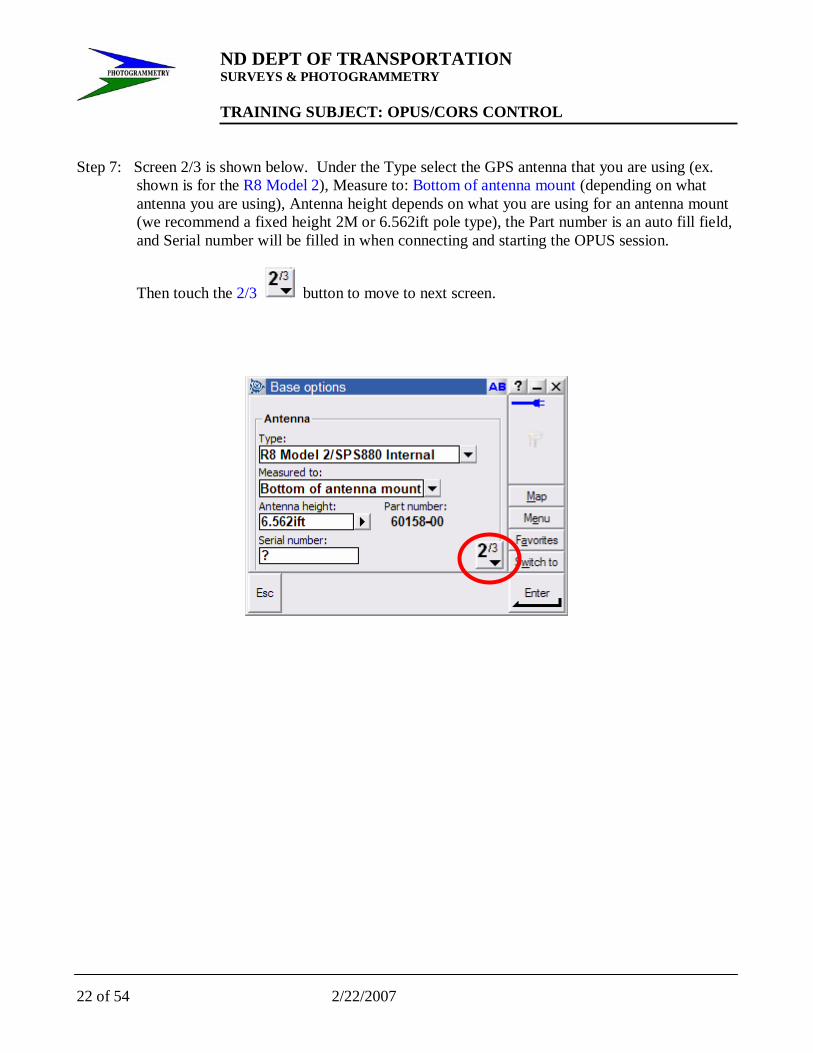
Step 7: Screen 2/3 is shown below. Under the Type select the GPS antenna that you are using (ex.
shown is for the R8 Model 2), Measure to: Bottom of antenna mount (depending on what antenna you are using), Antenna height depends on what you are using for an antenna mount (we recommend a fixed height 2M or 6.562ift pole type), the Part number is an auto fill field, and Serial number will be filled in when connecting and starting the OPUS session.
Then touch the 2/3 button to move to next screen.

ND DEPT OF TRANSPORTATION SURVEYS & PHOTOGRAMMETRY TRAINING SUBJECT: OPUS/CORS CONTROL
2/22/2007 23 of 54
Step 8: Leave screen 3/3 as its default, shown below. Select Enter.
Step 9: Next screen as shown, select Accept.
ND DEPT OF TRANSPORTATION SURVEYS & PHOTOGRAMMETRY TRAINING SUBJECT: OPUS/CORS CONTROL
24 of 54 2/22/2007
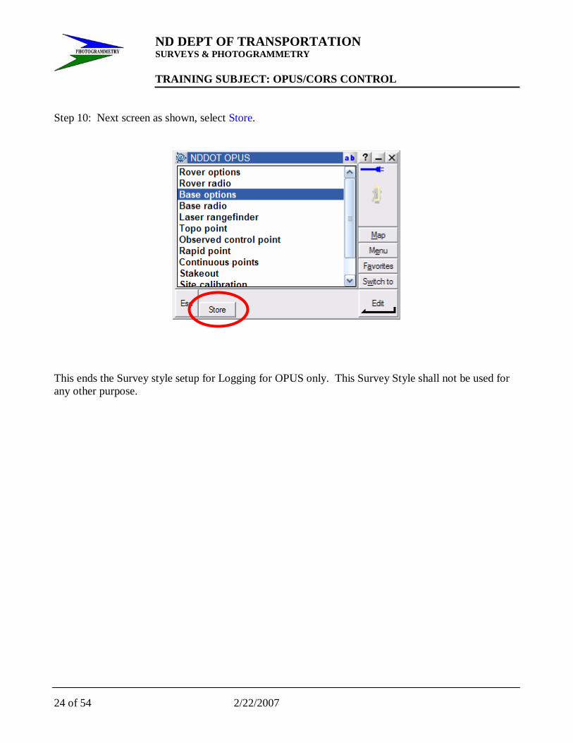
Step 10: Next screen as shown, select Store.
This ends the Survey style setup for Logging for OPUS only. This Survey Style shall not be used for any other purpose.
ND DEPT OF TRANSPORTATION SURVEYS & PHOTOGRAMMETRY TRAINING SUBJECT: OPUS/CORS CONTROL
2/22/2007 25 of 54
PROJECT CONTROL Project control shall be established using OPUS as set forth in Chapter 19-1.1 to 19-1.3 as follows:
19-1 SET PROJECT GROUND CONTROL 19-1.1 Project Control
The horizontal control shall be tied to the North Dakota coordinate system of 1983, north or south zone (be sure to use the correct zone), based on the North American Datum of 1983; (1996 Adjustment), NAD83 (CORS96) until the readjustment of the National Spatial Reference System (NSRS) is available. The readjustment is scheduled for completion February, 2007. The control will then be based on NAD 83 (NSRS).
The CONSULTANT shall set the PRIMARY CONTROL for the project by using a GPS survey to occupy pairs of monumented stations at both ends of the project and at intervals of every 2 to 3 miles throughout the project.
The Continuously Operating Reference Stations (CORS) will be used as the Master Control Network for all highway projects. The CORS stations used must surround (not all stations in a straight line or to one side) the project limits to prevent tilting of the coordinates and elevations. The CORS stations used as Master Control for the project will be picked from the following list:
BSMK Bismarck, ND MDR3 Medora, ND CLK1 Clark, SD PNR1 Pine River, MN WHN1 Whitney, NE BIL1 Billings, MN WDLM Wood Lake, MN
NOTE: other stations may be used if there are problems with the above stations.
The consultant shall use only geodetic grade Trimble GPS receivers (dual frequency, carrier-phase L1/L2) to collect all GPS data. A GPS receiver must occupy each PRIMARY CONTROL point for a MINIMUMof four (4) hours. This occupation time may be reduced in the future when NGS OPUS program is changed to provide the same accuracy level as the current four (4) hour accuracy (0.5 cm horizontally, 1.0 cm vertically).
The coordinates of the project control must be determined by using the NGS OPUS solutions.
The National Geodetic Survey operates the On-line Positioning User Service (OPUS) as a means to provide GPS users easer access to the National Spatial Reference System (NSRS). OPUS allows users to submit their GPS data files to NGS, where the data will
be processed to determine a position using NGS
computers and software. Each data file that is submitted will be processed with respect to three (3) CORS
sites.

ND DEPT OF TRANSPORTATION SURVEYS & PHOTOGRAMMETRY TRAINING SUBJECT: OPUS/CORS CONTROL
26 of 54 2/22/2007
It is important to have the correct antenna type and correct antenna height to the Antenna Reference Point. If this information is not correct, the elevations will be in error. The project control network point coordinates are acceptable when the OPUS solution statistics are as follows:
There are three ephemeris levels
1. Ultra-rapid (predicted) orbits (near real time) 2. Rapid orbits (one day delay) 3. Precise orbits (typical delay 10-14 days) highest accuracy.
Do not use the “ultra-rapid” ephemeris. Use only the “rapid” or “precise” ephemeris.
Initially the OPUS program picks the CORS stations for its solution. This solution should be checked to see if the CORS sites surround the project and if the solution is the best one. The data files should be submitted again with other sites chosen to see if the solution can be improved.
Review the OPUS printouts for each point observed. If any of the following conditions are NOT met, the point(s) must be observed again.
1. Use 95% or more of your observations. 2. Fixed at least 95% of the fixed ambiguities. 3. Overall RMS should seldom exceed 1.5cm (0.015m). Maximum 1.8cm (0.018m).
4. The peak-to-peak errors should seldom exceed 3cm (0.030m). Maximum 4cm (0.040m). This includes the Orthometric height value [Geoid03 NAVD88].
NOTE: the peak-to-peak error is the difference between the maximum and minimum value of each coordinate obtained from the three baseline solutions.
The CONSULTANT shall be responsible for using GPS and/or conventional total station survey techniques to establish both an intervisible network of Secondary control stations within project limits, and to tie in all photo control points, horizontally and vertically. The Secondary control survey and photo control points shall be positioned relative to the PRIMARY CONTROL.
NOTE: No GPS data (targets, alignment, topography, utilities, etc.) shall be collected using the “continuous Topo” option. PDOP shall be set no higher then 6 (we prefer 5). No project GPS calibration is to be used.
19-1.2 Vertical Control The vertical component of the survey shall be tied to the North American Vertical Datum of 1988 (NAVD 88).The OPUS solution will be used to determine the elevation component of each PRIMARY CONTROLpoint. No levels will be run from existing Bench Marks to determine PRIMARY CONTROL elevations.
19-1.3 Monumentation
PRIMARY CONTROL stations shall be monumented with 3/4"diameter and at least 18" long, iron pins. Secondary control stations and photo control points shall be monumented with a 5/8" diameter or larger and at least 18" long, iron pins. All PRIMARY CONTROL stations and Secondary control stations must be referenced to at least three nearby features with horizontal tie distances. These reference ties shall be documented on a sketch, in the project survey book, for each monument. Both the state plane and ground coordinate values (X, Y, & Z) should be noted along side of these sketches.
ND DEPT OF TRANSPORTATION SURVEYS & PHOTOGRAMMETRY TRAINING SUBJECT: OPUS/CORS CONTROL
2/22/2007 27 of 54
What Is CORS?
Continuously Operating Reference Stations
The National Geodetic Survey (NGS), an office of NOAA's National Ocean Service, coordinates two networks of continuously operating reference stations (CORS): the National CORS network and the Cooperative CORS network. Each CORS site provides Global Positioning System (GPS) carrier phase and code range measurements in support of 3-dimensional positioning activities throughout the United States and its territories (map).
Surveyors, GIS/LIS professionals, engineers, scientists, and others can apply CORS data to position points at which GPS data have been collected. The CORS system enables positioning accuracies that approach a few centimeters relative to the National Spatial Reference System, both horizontally and vertically.
The CORS system benefits from a multi-purpose cooperative endeavor involving many government, academic, commercial and private organizations. New sites are evaluated for inclusion according to established criteria. See our newest sites and their coordinates.
All national CORS data are available from NGS at their original sampling rate for 30 days. After that time, the data are decimated to a 30 second sampling rate. Cooperative CORS data are available from the participating organization that operates the respective site. Links to Web pages containing the Cooperative CORS data are provided from the NGS CORS Map and the Cooperative CORS Web page. Please note: Cooperative CORS members are only required to keep the latest 30 days of data.
National Geodetic Survey - CORS Team Modified August 31, 2006 http://www.ngs.noaa.gov/CORS/What_is_CORS.html

ND DEPT OF TRANSPORTATION SURVEYS & PHOTOGRAMMETRY TRAINING SUBJECT: OPUS/CORS CONTROL
28 of 54 2/22/2007

ND DEPT OF TRANSPORTATION SURVEYS & PHOTOGRAMMETRY TRAINING SUBJECT: OPUS/CORS CONTROL
2/22/2007 29 of 54
North Dakota
[D]

ND DEPT OF TRANSPORTATION SURVEYS & PHOTOGRAMMETRY TRAINING SUBJECT: OPUS/CORS CONTROL
30 of 54 2/22/2007
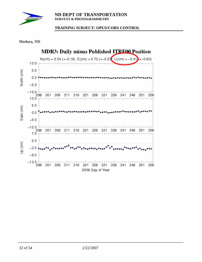
CORS stations should be checked before selecting which stations to be used for the OPUS solution. It is best to select the ones that have close to the same residuals in order to get a good solution. Following are examples of the “Time Series (60 day)” graphs located on the NGS website at http://www.ngs.noaa.gov/CORS/ . Select the stations on the national map. This will take you to a local map where you will again select the station by clicking on it to get to the station specific page. On the left hand side of this webpage you will find the link to the Time Series (60 day). Bismarck, ND

ND DEPT OF TRANSPORTATION SURVEYS & PHOTOGRAMMETRY TRAINING SUBJECT: OPUS/CORS CONTROL
2/22/2007 31 of 54
Minot, ND
ND DEPT OF TRANSPORTATION SURVEYS & PHOTOGRAMMETRY TRAINING SUBJECT: OPUS/CORS CONTROL
32 of 54 2/22/2007
Medora, ND

ND DEPT OF TRANSPORTATION SURVEYS & PHOTOGRAMMETRY TRAINING SUBJECT: OPUS/CORS CONTROL
2/22/2007 33 of 54
Clark, SD

ND DEPT OF TRANSPORTATION SURVEYS & PHOTOGRAMMETRY TRAINING SUBJECT: OPUS/CORS CONTROL
34 of 54 2/22/2007
Glendive, MT

ND DEPT OF TRANSPORTATION SURVEYS & PHOTOGRAMMETRY TRAINING SUBJECT: OPUS/CORS CONTROL
2/22/2007 35 of 54
Pine River, MN

ND DEPT OF TRANSPORTATION SURVEYS & PHOTOGRAMMETRY TRAINING SUBJECT: OPUS/CORS CONTROL
36 of 54 2/22/2007
Wood Lake, MN

ND DEPT OF TRANSPORTATION SURVEYS & PHOTOGRAMMETRY TRAINING SUBJECT: OPUS/CORS CONTROL
2/22/2007 37 of 54
Ekalaka, MT

ND DEPT OF TRANSPORTATION SURVEYS & PHOTOGRAMMETRY TRAINING SUBJECT: OPUS/CORS CONTROL
38 of 54 2/22/2007
Online Positioning User Service
Using OPUS
OPUS Guidelines
The following items describe in greater detail the guidelines for uploading data to OPUS.
1. EMAIL You may enter either the email address for the machine that you are using to submit your data file or another email address where you would like the results to be sent.
2. DATA FILE OPUS accepts data in either RINEX format or selected receiver formats. Your RINEX file may be UNIX compressed, gzipped or pkzipped. The file may also be Hatanaka compressed (yyd suffix). You may also submit multiple files in a zip archive, but your selected options will be applied to all of the files in the archive. NGS software will only process dual-frequency, carrier-phase data (L1 & L2). Single frequency data (L1 only) will not be processed. You may only submit data from a dual-frequency receiver. The data must have been collected for a minimum of 2 hours and from a stationary antenna. Your collection rate must be 1,2,3,5,10,15 or 30 seconds.
The receiver formats that OPUS will accept are those that can be processed by Teqc.
3. ANTENNA TYPE The vertical distance from the phase center of the GPS antenna to the Antenna Reference Point (ARP) is needed in order to connect the GPS measurements to the monument or point whose position you are trying to determine. NGS has measured these offsets as well as how these offsets change with

ND DEPT OF TRANSPORTATION SURVEYS & PHOTOGRAMMETRY TRAINING SUBJECT: OPUS/CORS CONTROL
2/22/2007 39 of 54
direction to the GPS satellites (see GPS Height Measurements). Most GPS antennas suitable for geodetic work have been calibrated by NGS and new antennas are calibrated when they become available (see GPS Antenna Calibration). The NGS software applies these calibration corrections for the particular antenna type that you are using in order to ensure the greatest possible height accuracy.
The "Select the antenna type" box will display all the antennas that have been calibrated by NGS and whose phase center offsets and phase variations are known. The antenna type names are very similar and should be clearly recognizable from the GPS antenna model number. The model or part number included in the antenna type may be found in almost every case stamped on the antenna. In every case, the model number has been preceded by a 3-character abbreviation for the manufacturer. In many cases the model numbers in this list have an additional designation appended to their name. These designations are: "GP" or "gp" for groundplane, "rd" for radome; and "CR" or "cr" for choke ring. The + or – symbols indicate if these features have been added (+) or removed (-) from the normal configuration of that antenna model. To avoid confusion, a "-" symbol that may have literally appeared in the model number stamped on the antenna may have been changed to a "." symbol in this list.
For pictures, diagrams and more information on GPS antennas and calibrations see the NGS web site for GPS Antenna Calibration.
3 Char ID Maufacturer AER Aeroantenna AOA Allan Osborne Associates ASH Ashtech JPL Jet Propulsion Lab JPS Javad LEI Leica MAC Macrometer MAG Magellan MPL Micro Pulse NAV NavCom NOV NovAtel SEN Sensor Systems SOK Sokkia SPP Spectra Precision TOP or TPS Topcon TRM Trimble NGS National Geodetic Survey

ND DEPT OF TRANSPORTATION SURVEYS & PHOTOGRAMMETRY TRAINING SUBJECT: OPUS/CORS CONTROL
40 of 54 2/22/2007
OPUS does not read the header of the RINEX for antenna or height information. With the exception of parentheses, periods, and hyphens, which may be omitted or replaced in order to have a more uniform naming convention, the model number stamped on your GPS antenna should very closely match a model number in this file. If you have trouble finding a match, look at GPS Antenna Calibration, which has photographs and engineering drawings of most of the calibrated antennas.
If you still do not find a match, you should select "NONE" (default). Selecting "NONE" causes OPUS to ignore the phase center variations (since the antenna is unknown). In this case your results will contain a warning that no antenna type was specified and that the computed position refers to the phase center of the antenna (if 0.0 is entered for the antenna height) rather than to the Antenna Reference Point. Missing or incorrect antenna calibrations primarily affect height measurments and have been seen to cause height errors as large as 10 cm.
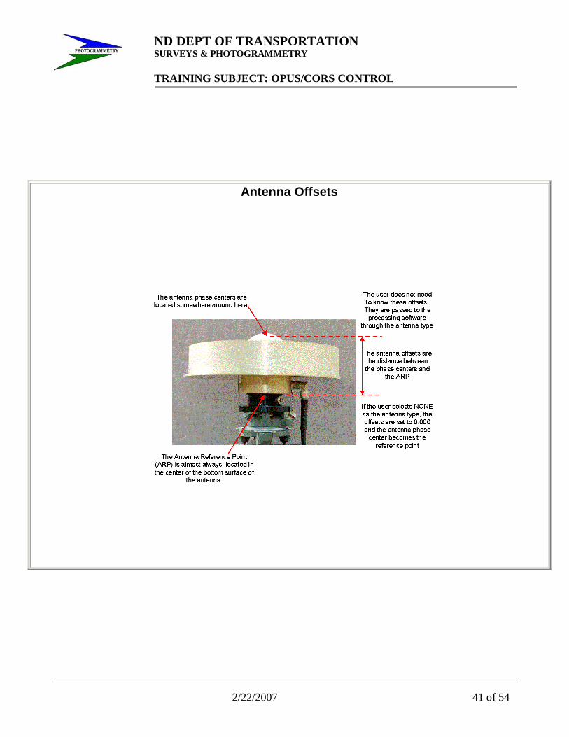
4. ANTENNA HEIGHT To complete the connection of the GPS height measurement to your monument or point, the Height of the Antenna Reference Point (ARP) in meters above your mark must be entered. OPUS does not read the information in the header of the RINEX file. The position that a user wants is most often that of a physical mark usually located directly beneath the antenna. The antenna phase center is not a physical point, but its location with respect to a physical feature on the antenna can be determined through a set of calibration measurements. The vector from this antenna reference point (ARP), which is usually the center of the bottom of the antenna, to the phase center is called the antenna offset. There are separate antenna offsets for the L1 and L2 carrier phase data.
In order to greatly simplify the correct use of antenna offsets, NGS has calibrated, and continues to calibrate, nearly all the GPS antennas likely to be used for geodetic measurements (see GPS Antenna Calibrations ). This eliminates the need for the user to ever know what these offsets are. All the antenna calibrations are available to the NGS software and are sorted by antenna type . The user only needs to identify the appropriate antenna type that was used to collect the data that is being submitted. Only the processing software ever needs to know the actual values of these offsets and calibrations.
Since the antenna offsets are obtained by selecting the correct antenna type, the height measurements are completed by entering the distance from the ARP to a mark or monument on the ground. The relationship between the antenna offsets and the antenna height is illustrated and discussed below.
5. SELECT OPTIONS OPUS offers a number of options allowing the user some flexibility in the way solutions are performed and results reported back. These are described in links on the options page.
ND DEPT OF TRANSPORTATION SURVEYS & PHOTOGRAMMETRY TRAINING SUBJECT: OPUS/CORS CONTROL
2/22/2007 41 of 54
Antenna Offsets

ND DEPT OF TRANSPORTATION SURVEYS & PHOTOGRAMMETRY TRAINING SUBJECT: OPUS/CORS CONTROL
42 of 54 2/22/2007

ND DEPT OF TRANSPORTATION SURVEYS & PHOTOGRAMMETRY TRAINING SUBJECT: OPUS/CORS CONTROL
2/22/2007 43 of 54
OPUS Output Page
A sample OPUS Output Page is shown below. An explanation of each of the items that appears in the output page follows the sample page.
NGS OPUS SOLUTION REPORT ========================
USER: [email protected] DATE: October 27, 2004
RINEX FILE: 7615289n.04o TIME: 18:49:54 UTC
SOFTWARE: page5 0407.16 master7.pl START: 2004/10/15 13:37:00
EPHEMERIS: igr12925.eph [rapid] STOP: 2004/10/15 18:10:00
NAV FILE: brdc2880.04n OBS USED: 8686 / 8804 : 99%
ANT NAME: ASH700829.3 SNOW # FIXED AMB: 41 / 42 : 98%
ARP HEIGHT: 1.295 OVERALL RMS: 0.020 (m)
REF FRAME: NAD83(CORS96)(EPOCH:2002.0000) ITRF00 (EPOCH:2004.7887)
X: -552474.327(m) 0.015(m) -552475.001(m) 0.015(m) Y: -4664767.953(m) 0.021(m) -4664766.631(m) 0.021(m) Z: 4300548.721(m) 0.024(m) 300548.654(m) 0.024(m)
LAT: 42 39 59.51026 0.007(m) 42 39 59.53576 0.008(m)
E LON: 263 14 44.18589 0.013(m) 263 14 44.14967 0.013(m) W LON: 96 45 15.81411 0.013(m) 96 45 15.85033 0.013(m)
EL HGT: 314.705(m) 0.041(m) 313.753(m) 0.033(m) ORTHO
HGT: 340.240(m) 0.041(m) [Geoid03 NAVD88]

ND DEPT OF TRANSPORTATION SURVEYS & PHOTOGRAMMETRY TRAINING SUBJECT: OPUS/CORS CONTROL
44 of 54 2/22/2007
UTM COORDINATES STATE PLANE COORDINATES
UTM (Zone 14) SPC (4002 SD S) Northing (Y) [meters] 4726229.423 43336.983 Easting (X) [meters] 684026.367 893325.488 Convergence [degrees] 1.52234197 2.46893915 Point Scale 1.00001666 1.00004366 Combined Factor 0.99996731 0.99999430 US NATIONAL GRID DESIGNATOR: 14TPN8402626229(NAD 83)
BASE STATIONS USED
PID DESIGNATION LATITUDE LONGITUDE DISTANCE(m)
AI1569 NLGN NELIGH CORS ARP N421224.250 W0974743.043 99724.2
DF7469 SDSF EROS DATA CENTER CORS ARP
N434401.727 W0963718.541 119065.7
AH5054 OMH1 OMAHA 1 CORS ARP N414641.765 W0955440.671 120751.8
NEAREST NGS PUBLISHED CONTROL POINT
NM0874 D 276 N423846. W0964505. 2286.4 This position was computed without any knowledge by the National Geodetic Survey regarding equipment or field operating procedures used.

ND DEPT OF TRANSPORTATION SURVEYS & PHOTOGRAMMETRY TRAINING SUBJECT: OPUS/CORS CONTROL
2/22/2007 45 of 54
OPUS Diagnostics Messages:
OPUS will write any error or warning messages to the top of the output page. In the event of an error, your data will be examined by data analysts to try to improve OPUS reliability. A solution will, hopefully, be sent in a few days.
USER: Your email address is listed here
RINEX FILE: The RINEX observation file name and an Opus sequence number which ties the Opus solution to your submission
DATE: The date this solution was run
TIME: The Universal Time (UTC) the solution was run
SOFTWARE: The version of PAGES used for this processing
EPHEMERIS: The ephemeris file selected to process the data
NAV FILE: The RINEX navigation file selected
ANT NAME: The antenna name selected
ARP HEIGHT: The height you entered in meters from the monument to the antenna reference point
START: The date & time your data started
STOP: The date & time your data ended
OBS USED: The number of usable observations / the number of total observations in your data
# FIXED AMB: The number of fixed ambiguities / the total number of ambiguities
OVERALL RMS: The formal statistical root mean square error of your solution in meters
REF FRAME: Under the NAD83 heading are coordinates referenced to NAD83.
X: The NAD83 Cartesian coordinates and peak-to-peak errors in meters

ND DEPT OF TRANSPORTATION SURVEYS & PHOTOGRAMMETRY TRAINING SUBJECT: OPUS/CORS CONTROL
46 of 54 2/22/2007
Y:
Z:
Explanation of peak-to-peak errors and accuracy of the result
LAT:
E LON:
W LON:
ELLIPSOID HGT:
The NAD83 geodetic coordinates (height is in meters) and peak-to-peak errors (in meters). The GRS80 ellipsoid is used in the calculations. Explanation of peak-to-peak errors and accuracy of the result
ORTHO HGT: The orthometric height (in meters) obtained by combining the ellipsoid height with the geoid height from the specified geoid and vertical datum.
NORTHING:
EASTING:
The Universal Transver Mercator (UTM) coordinates (in meters) are listed along with the corresponding zone. Also listed are the State Plane Coordinates (SPC) along with the zone number and State Code.
MERIDIAN CONVERGENCE:
POINT SCALE:
COMBINED FACTOR:
The Meridian Convergency (in degrees) and the Point Scale (unitless) corresponding to the projection are also given for the UTM and SPC projections. Multiplying the combined factor by the ground distance gives, approximately, the grid distance. Dividing the grid distance by the combined factor gives, approximately, the ground distance.
REF FRAME: The following coordinates are in the specified ITRF coordinates for the indicated epoch.
X:
Y:
Z:
The ITRF Cartesian coordinates and peak-to-peak errors in meters
LAT: The ITRF geodetic coordinates (height is in meters) and peak-to-peak errors
ND DEPT OF TRANSPORTATION SURVEYS & PHOTOGRAMMETRY TRAINING SUBJECT: OPUS/CORS CONTROL
2/22/2007 47 of 54
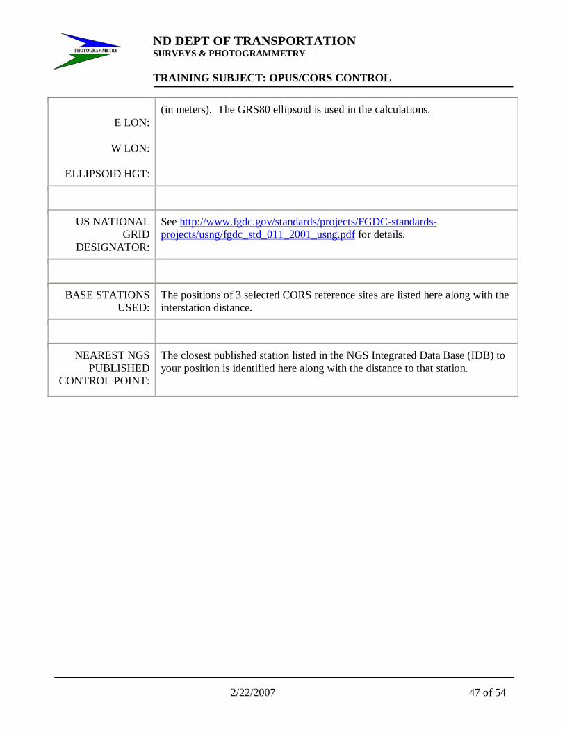
E LON:
W LON:
ELLIPSOID HGT:
(in meters). The GRS80 ellipsoid is used in the calculations.
US NATIONAL GRID
DESIGNATOR:
See http://www.fgdc.gov/standards/projects/FGDC-standards-projects/usng/fgdc_std_011_2001_usng.pdf for details.
BASE STATIONS USED:
The positions of 3 selected CORS reference sites are listed here along with the interstation distance.
NEAREST NGS PUBLISHED
CONTROL POINT:
The closest published station listed in the NGS Integrated Data Base (IDB) to your position is identified here along with the distance to that station.

ND DEPT OF TRANSPORTATION SURVEYS & PHOTOGRAMMETRY TRAINING SUBJECT: OPUS/CORS CONTROL
48 of 54 2/22/2007
Discussion
How are the solutions obtained ?
OPUS-derived ITRF positional coordinates are the average of 3 distinct single-baseline solutions computed by double-differenced, carrier-phase measurements from 3 different National CORS sites using program PAGES. The reference ITRF coordinates for the CORS have been obtained from the NGS Integrated Data Base (IDB)and have been updated to the midpoint of the time interval when the submitted data were observed. Hence, OPUS-derived ITRF coordinates correspond to the position of the point at this instant in time. Points in the coterminous United States move between 9 and 22 mm/yr horizontally, relative to ITRF.
OPUS-derived NAD 83 positional coordinates are also the average of 3 distinct single-baseline solutions. The procedure followed to compute final NAD 83 coordinates at epoch 2002.0 is as follows:
First, the 3 derived ITRF intersite vector components, given at the midpoint of the data time interval, are individually transformed to the NAD 83 reference frame. Secondly, the NAD 83 coordinates of the three reference CORS stations, retrieved from the NGS IDB, are also updated to the midpoint of the interval, applying the NAD 83 velocities available from the data sheet. Vector components and CORS NAD 83 coordinates are added to determine 3 different values of the coordinates of the unknown point on the NAD 83 frame at the midpoint epoch. These 3 quantities are averaged to determine a unique value for the coordinates of the point at this epoch. Finally, these coordinates are then transformed in time to the epoch date of January 1, 2002 by using the NAD 83 velocity for the point as predicted by the HTDP (Horizontal Time-Dependent Positioning) software.
Because NAD 83 positional coordinates in the coterminous United States are referenced to the North American tectonic plate, NAD 83 velocities are typically very small. NAD 83 velocities in excess of 5 mm/yr, however, are prevalent in States along the Pacific Coast. Note that the OPUS-derived NAD 83 positional coordinates are not obtained by a direct transformation of their corresponding ITRF coordinates
While 3 single-baseline solutions are computed, the solutions can not be considered as completely independent. Local biases at the user 's submitted station will not be averaged away by the combination. For example, local multipath error, or error in the height of the Antenna Reference Point (ARP) will not be evident in looking at the solution variation. On the other hand, use of 3 single-baselines does provide a gauge of error contributions from the various National CORS stations.

ND DEPT OF TRANSPORTATION SURVEYS & PHOTOGRAMMETRY TRAINING SUBJECT: OPUS/CORS CONTROL
2/22/2007 49 of 54
What is the accuracy of the result ?
Accuracy estimates for GPS reductions obtained by formal error propagation are notoriously optimistic. For this reason, OPUS does not rely only on the formal errors. Instead, the peak-to-peak error, or error range is provided for each coordinate component (XYZ and NEU). The peak-to-peak error is the difference between the maximum and the minimum value of a coordinate obtained from the 3 baseline solutions. A completely random population with a standard deviation of 1.0 cm, when sampled 3 times, will have a peak-to-peak error of 3.3 cm or less, 95% of the time. In other words, if you see a peak-to-peak variation in the ellipsoidal height of 3.3 cm or higher, there is a 5% chance that such a variation came from data that had a 1.0 cm (one sigma) precision. It is, of course, more likely that 3.3 cm or higher variation indicates a precision larger than 1.0 cm.
A key element, which bears repeating, is that accuracy estimates depend upon freedom from systematic error. For example, if there is an error in identification of the antenna type, the wrong antenna phase center variation model and wrong phase center-ARP offsets will be applied to the data. This could lead to errors of 10 cm or more that will not be displayed in the peak-to-peak error value.
The advantage of providing a peak-to-peak error measure obtained from 3 baselines solved from different National CORS is that the error range also reflects the errors in the reference coordinates of the CORS stations. The accuracies that can be obtained with modern GPS receivers and geodetic models are such that as your observational time spans get longer your results will improve so that the small errors in the reference coordinates can become a relatively more significant component of the total error. In fact, on the average, one should obtain larger peak-to-peak errors in the NAD 83 coordinates, when compared to the ITRF coordinates, from the same observational data. This is due to the procedures used to derive the CORS coordinates. To serve our users, the NAD 83 coordinates of the National CORS are updated less frequently than ITRF coordinates. However, this also results in the NAD 83 coordinates being somewhat less accurate.
Because of the automatic character of OPUS solutions, and the critical nature of elements such as antenna identification and ARP height measurement, NGS provides a disclaimer to all OPUS results, “This position was computed without any knowledge by the National Geodetic Survey regarding equipment characteristics or field operating procedures.”
How to get a more accurate result
The single best way to get a more accurate result is to submit a longer time span of data. While we currently accept a minimum of 2 hours of data, we use at least 4 hours of data. As an example, our height modernization surveys, which routinely achieve 1 cm, one sigma, ellipsoidal height accuracy, require three or more sessions, each at least 5.5 hours long, on two or more days, where two of the observation time spans are offset to sample different satellite geometries. While good results can be obtained with 2 hour solutions, we have found that longer time spans are consistently more reliable.
In addition, using a longer time span of data allows greater averaging of multipath error. Alternatively, if one is able to use a multipath-suppressing antenna and/or receiver, (e.g. choke-ring antennas, --- correlation receivers), then more accurate results should be obtained from a given amount of data.
ND DEPT OF TRANSPORTATION SURVEYS & PHOTOGRAMMETRY TRAINING SUBJECT: OPUS/CORS CONTROL
50 of 54 2/22/2007
However, even if a such improved antennas/receivers are used locally, longer data sets are still useful, since such antennas and receivers are not always used at the National CORS sites, themselves.
No improvement will be obtained by submitting GPS data taken every 5 seconds or, even, every 1 second. Since the time correlation of multipath error is typically on the order of 10 to 20 minutes and given the variety of data rates within the CORS network, the data rates used for OPUS solutions are fixed at 30 seconds.
If you submitted your solution very soon after taking your data, then it is possible that predicted orbits, rather than precise, post-fit orbits were used to obtain your solution. The priority for orbit selection is:
IGS precise orbits (typical delay 10-14 days) highest accuracy IGS rapid orbits (one day delay) IGS ultra-rapid (predicted) orbits (near real-time)
The orbit source will be indicated on your solution. There is essentially no difference in accuracy between OPUS solutions using the rapid or precise orbits due to the moderate lengths of the base lines. However, if the predicted orbit was used, you may wish to resubmit your solution at a later time when a more accurate orbit is available. In addition, not all CORS data are available at NGS within one hour, and sometimes, not available within one day. This means that more distant CORS stations may have been used for the OPUS solution. While baseline length is much less critical than measurement time span, this can sometimes also be a reason to resubmit your data .
It is possible that more accurate results can be obtained for a given set of data through manual processing through suitable software. Such processing can include manual cycle slip editing, deletion of outliers, incorporation of local meteorological measurements, and experimentation with allocation of tropospheric parameters, variable cut-off angle, and different constraints of the carrier phase ambiguities to integer values. However, manual processing alone is not a guarantee of accurate results. Accurate results, particularly for long lines, depend on the fidelity of the geodetic models incorporated in the GPS reduction software. OPUS has an extensive set of geodetic models in the PAGES software engine and the reliability of the automated processing (data editing, integer fixing, etc.) has been repeatedly demonstrated for NGS’s own processing.
At the highest level of accuracies, one is limited by the accuracy of the reference coordinates of the National CORS. The NAD 83 datum is generally less accurate than that of the ITRF. One could take the ITRF coordinate, and apply the Helmert transformation to generate an “NAD 83” coordinate (this can be done with HTDP). If one does this, one will actually obtain a coordinate that has good consistency with the National CORS, but will have less consistency with the NAD 83 coordinates in the NGS Integrated Data Base. NGS is currently engaged in a new GPS survey across the country to obtain 2 cm (2 sigma) ellipsoid heights for 2002. When this effort is completed, the nation will have a uniformly high level of accuracy in both the NAD 83 and the ITRF reference systems. More information is available at our web page on the New Reference System.

ND DEPT OF TRANSPORTATION SURVEYS & PHOTOGRAMMETRY TRAINING SUBJECT: OPUS/CORS CONTROL
2/22/2007 51 of 54
As a final note, please, triple check the antenna type and the height of the ARP submitted to each OPUS run. A chain is only as strong as its weakest link. Antenna type and the height of the ARP are critical links in the GPS data reduction chain.
What to look for in a quality solution
There are no absolute rules, but we can certainly provide some guidance on OPUS solutions.
Make sure the antenna type and the ARP height are correct.
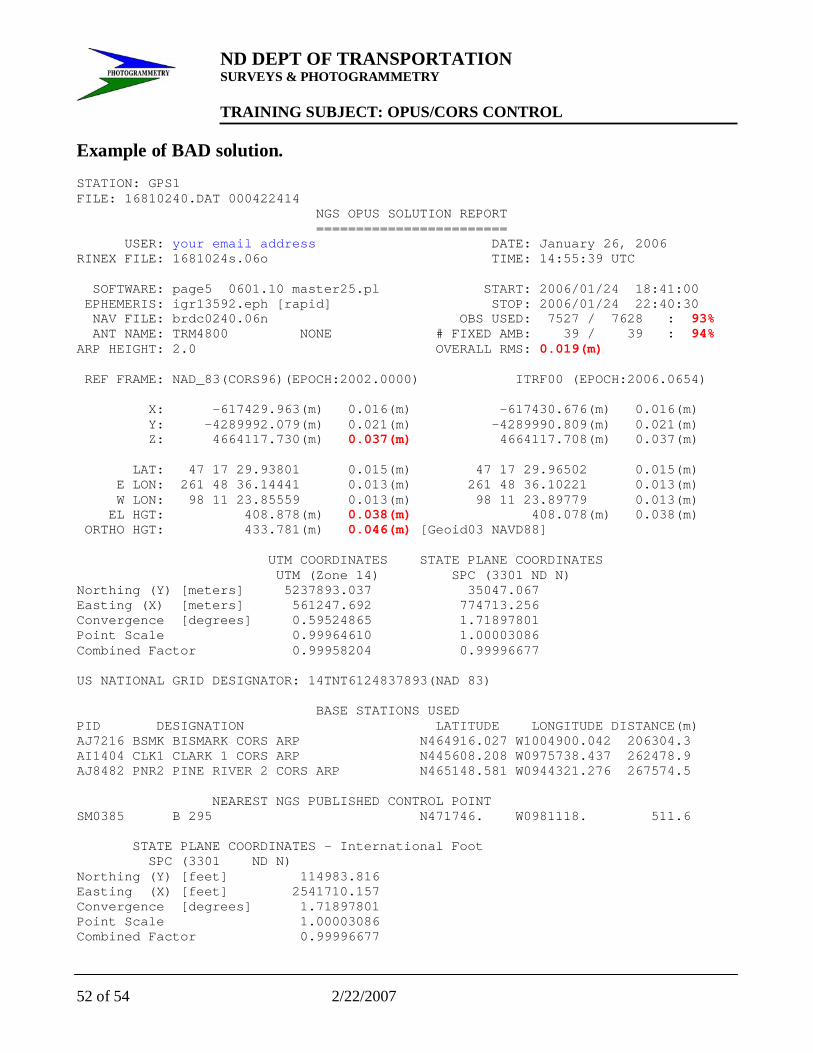
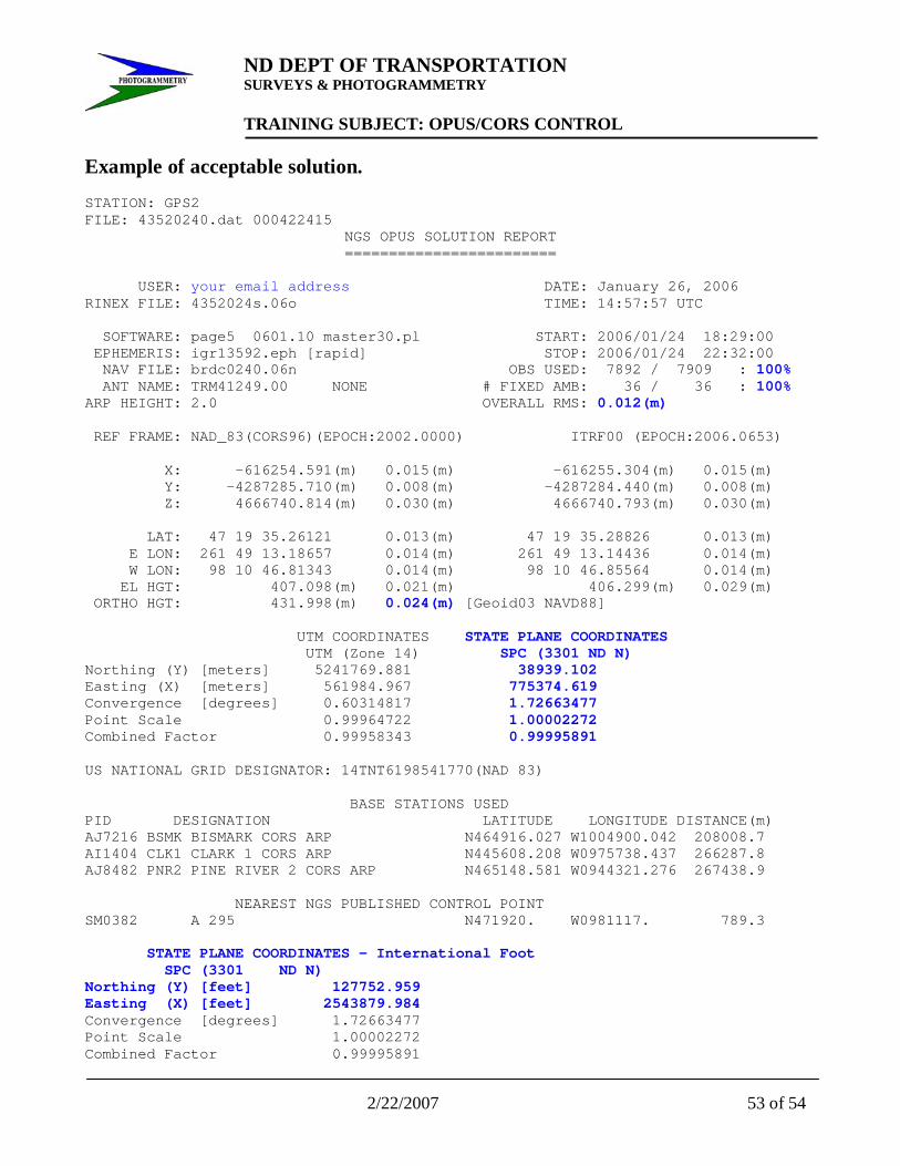
National Geodetic Survey - OPUS Team Last modified: May 17, 2004 http://www.ngs.noaa.gov/OPUS/Using_OPUS.html Reviewing Solutions The following pages give examples of poor and acceptable OPUS results. As per Chapter 19-1.1 these conditions must be met. Review the OPUS printouts for each point observed. If any of the following conditions are NOT met, the point(s) must be observed again. 1. Use 95% or more of your observations. 2. Fixed at least 95% of the fixed ambiguities. 3. Overall RMS should seldom exceed 1.5cm (0.015m). Maximum 1.8cm (0.018m). 4. The peak-to-peak errors should seldom exceed 3cm (0.030m). Maximum 4cm (0.040m). This includes the Orthometric height value [Geoid03 NAVD88]. NOTE: the peak-to-peak error is the difference between the maximum and minimum value of each coordinate obtained from the three baseline solutions.
ND DEPT OF TRANSPORTATION SURVEYS & PHOTOGRAMMETRY TRAINING SUBJECT: OPUS/CORS CONTROL
52 of 54 2/22/2007
Example of BAD solution. STATION: GPS1 FILE: 16810240.DAT 000422414 NGS OPUS SOLUTION REPORT ========================
USER: your email address DATE: January 26, 2006 RINEX FILE: 1681024s.06o TIME: 14:55:39 UTC SOFTWARE: page5 0601.10 master25.pl START: 2006/01/24 18:41:00 EPHEMERIS: igr13592.eph [rapid] STOP: 2006/01/24 22:40:30 NAV FILE: brdc0240.06n OBS USED: 7527 / 7628 : 93% ANT NAME: TRM4800 NONE # FIXED AMB: 39 / 39 : 94% ARP HEIGHT: 2.0 OVERALL RMS: 0.019(m) REF FRAME: NAD_83(CORS96)(EPOCH:2002.0000) ITRF00 (EPOCH:2006.0654) X: -617429.963(m) 0.016(m) -617430.676(m) 0.016(m) Y: -4289992.079(m) 0.021(m) -4289990.809(m) 0.021(m) Z: 4664117.730(m) 0.037(m) 4664117.708(m) 0.037(m) LAT: 47 17 29.93801 0.015(m) 47 17 29.96502 0.015(m) E LON: 261 48 36.14441 0.013(m) 261 48 36.10221 0.013(m) W LON: 98 11 23.85559 0.013(m) 98 11 23.89779 0.013(m) EL HGT: 408.878(m) 0.038(m) 408.078(m) 0.038(m) ORTHO HGT: 433.781(m) 0.046(m) [Geoid03 NAVD88] UTM COORDINATES STATE PLANE COORDINATES UTM (Zone 14) SPC (3301 ND N) Northing (Y) [meters] 5237893.037 35047.067 Easting (X) [meters] 561247.692 774713.256 Convergence [degrees] 0.59524865 1.71897801 Point Scale 0.99964610 1.00003086 Combined Factor 0.99958204 0.99996677 US NATIONAL GRID DESIGNATOR: 14TNT6124837893(NAD 83) BASE STATIONS USED PID DESIGNATION LATITUDE LONGITUDE DISTANCE(m) AJ7216 BSMK BISMARK CORS ARP N464916.027 W1004900.042 206304.3 AI1404 CLK1 CLARK 1 CORS ARP N445608.208 W0975738.437 262478.9 AJ8482 PNR2 PINE RIVER 2 CORS ARP N465148.581 W0944321.276 267574.5 NEAREST NGS PUBLISHED CONTROL POINT SM0385 B 295 N471746. W0981118. 511.6 STATE PLANE COORDINATES - International Foot SPC (3301 ND N) Northing (Y) [feet] 114983.816 Easting (X) [feet] 2541710.157 Convergence [degrees] 1.71897801 Point Scale 1.00003086 Combined Factor 0.99996677
ND DEPT OF TRANSPORTATION SURVEYS & PHOTOGRAMMETRY TRAINING SUBJECT: OPUS/CORS CONTROL
2/22/2007 53 of 54
Example of acceptable solution. STATION: GPS2 FILE: 43520240.dat 000422415
NGS OPUS SOLUTION REPORT ========================
USER: your email address DATE: January 26, 2006 RINEX FILE: 4352024s.06o TIME: 14:57:57 UTC SOFTWARE: page5 0601.10 master30.pl START: 2006/01/24 18:29:00 EPHEMERIS: igr13592.eph [rapid] STOP: 2006/01/24 22:32:00 NAV FILE: brdc0240.06n OBS USED: 7892 / 7909 : 100% ANT NAME: TRM41249.00 NONE # FIXED AMB: 36 / 36 : 100% ARP HEIGHT: 2.0 OVERALL RMS: 0.012(m) REF FRAME: NAD_83(CORS96)(EPOCH:2002.0000) ITRF00 (EPOCH:2006.0653) X: -616254.591(m) 0.015(m) -616255.304(m) 0.015(m) Y: -4287285.710(m) 0.008(m) -4287284.440(m) 0.008(m) Z: 4666740.814(m) 0.030(m) 4666740.793(m) 0.030(m) LAT: 47 19 35.26121 0.013(m) 47 19 35.28826 0.013(m) E LON: 261 49 13.18657 0.014(m) 261 49 13.14436 0.014(m) W LON: 98 10 46.81343 0.014(m) 98 10 46.85564 0.014(m) EL HGT: 407.098(m) 0.021(m) 406.299(m) 0.029(m) ORTHO HGT: 431.998(m) 0.024(m) [Geoid03 NAVD88] UTM COORDINATES STATE PLANE COORDINATES UTM (Zone 14) SPC (3301 ND N) Northing (Y) [meters] 5241769.881 38939.102 Easting (X) [meters] 561984.967 775374.619 Convergence [degrees] 0.60314817 1.72663477 Point Scale 0.99964722 1.00002272 Combined Factor 0.99958343 0.99995891 US NATIONAL GRID DESIGNATOR: 14TNT6198541770(NAD 83) BASE STATIONS USED PID DESIGNATION LATITUDE LONGITUDE DISTANCE(m) AJ7216 BSMK BISMARK CORS ARP N464916.027 W1004900.042 208008.7 AI1404 CLK1 CLARK 1 CORS ARP N445608.208 W0975738.437 266287.8 AJ8482 PNR2 PINE RIVER 2 CORS ARP N465148.581 W0944321.276 267438.9 NEAREST NGS PUBLISHED CONTROL POINT SM0382 A 295 N471920. W0981117. 789.3 STATE PLANE COORDINATES - International Foot SPC (3301 ND N) Northing (Y) [feet] 127752.959 Easting (X) [feet] 2543879.984 Convergence [degrees] 1.72663477 Point Scale 1.00002272 Combined Factor 0.99995891

ND DEPT OF TRANSPORTATION SURVEYS & PHOTOGRAMMETRY TRAINING SUBJECT: OPUS/CORS CONTROL
54 of 54 2/22/2007
Additional Notes:
![2 PHOTOGRAMMETRY HISTORY OF EARLY · PDF fileplate for roll film [Gruner, 1977]. F. Stolze discovered the principle of the ... Center for Photogrammetric Training History of Photogrammetry](https://img.pdfslide.us/doc/110x75/5abd99bd7f8b9aa3088bd4a0/2-photogrammetry-history-of-early-for-roll-film-gruner-1977-f-stolze-discovered.jpg)