Embed Size (px)
Citation preview
TRAINING GUIDE
FOR X-RAY SERVICE COMPANY (XSC)
PERSONNEL
PERFORMING EQUIPMENT PERFORMANCE EVALUATIONS (EPE)
For additional information or questions contact:
Texas Department of State Health Services Regulatory Services Division,
Environmental and Consumer Health Section, Inspection Unit-Radiation Group
512-834-6770
DEPARTMENT OF STATE HEALTH SERVICES
(DSHS) RADIATION CONTROL PROGRAM

2
TABLE OF CONTENTS
TITLE PAGE I Introduction .......................................................................... 3 II The Regulations ................................................................... 3 III The EPE Form ..................................................................... 4 IV Remote Inspections.............................................................. 5 V EPE Timeframes .................................................................. 5 VI Training Regulations ............................................................ 6 VII Equipment Tests Training .................................................... 6 VIII Training Format/Documentation........................................... 6 IX EPE Tests Required by Rule for Radiographic Units ............................................... 11 X X-ray Unit Identification on the EPE Form.......................... 11 XI Timer Accuracy .................................................................. 12 XII Exposure Reproducibility.................................................... 13 XIII KVP....................................................................................14 XIV Tube Stability ..................................................................... 15 XV Collimation ......................................................................... 15 XV A Points to Remember ................................................15 XV B Determining the Projected Field Size ....................... 15 XV C Allowable Diameter for Circular X-ray Fields............ 18 XV D Dental Intraoral Units ............................................... 19 XV E Dental Extraoral Units .............................................. 20 XV F Veterinary................................................................. 21 XV G General Radiographic.............................................. 21 XVI Source to Image Distance .................................................. 23 XVII Center Alignment................................................................ 23 XVIII Linearity.............................................................................. 24 XIX Entrance Exposure-Dental ................................................. 25

3
TRAINING GUIDE FOR X-RAY SERVICE COMPANY (XSC) PERSONNEL PERFORMING EQUIPMENT PERFORMANCE EVALUATIONS (EPE)
I. Introduction:
This guide has been developed to assist x-ray service companies (XSC) in training their personnel to assure the equipment and associated reports meet regulatory requirements. It should also:
• improve understanding of rules and regulations • promote uniform testing procedures • enhance the accuracy on Equipment Performance Evaluation (EPE) forms • improve technical service to the x-ray registrant • help avoid violations to both the registrant and the service company • provide guidance for training documentation of XSC personnel
II. The Regulations:
As a prerequisite to training, staff should be familiar with the Texas Regulations that apply both to the registrant and the service company.
• The format:
o 25 Texas Administrative Code (TAC) is the title o Table of Contents o Texas Register Format §289 is the chapter. o 25 TAC §289.226 (machine use), §289.227(general radiographic)
§289.232 (dental), and (§289.233 (veterinary) are the sections containing rules specific to the modality. The format is:
(a) subsection • (1) paragraph
o (A) subparagraph (i) clause
• (1) sub clause o (-a-) item
(-1-) sub item The rules may be located at: www.dshs.state.tx.us/radiation/rules
DEPARTMENT OF STATE HEALTH SERVICES RADIATION CONTROL PROGRAM
4
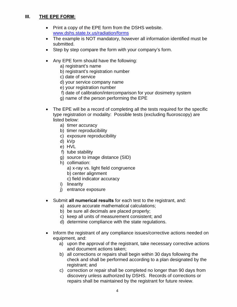
III. THE EPE FORM:
• Print a copy of the EPE form from the DSHS website. www.dshs.state.tx.us/radiation/forms
• The example is NOT mandatory, however all information identified must be submitted.
• Step by step compare the form with your company’s form. • Any EPE form should have the following:
a) registrant’s name b) registrant’s registration number c) date of service d) your service company name e) your registration number f) date of calibration/intercomparison for your dosimetry system g) name of the person performing the EPE
• The EPE will be a record of completing all the tests required for the specific type registration or modality: Possible tests (excluding fluoroscopy) are listed below:
a) timer accuracy b) timer reproducibility c) exposure reproducibility d) kVp e) HVL f) tube stability g) source to image distance (SID) h) collimation:
a) x-ray vs. light field congruence b) center alignment c) field indicator accuracy
i) linearity j) entrance exposure
• Submit all numerical results for each test to the registrant, and:
a) assure accurate mathematical calculations; b) be sure all decimals are placed properly; c) keep all units of measurement consistent; and d) determine compliance with the state regulations.
• Inform the registrant of any compliance issues/corrective actions needed on
equipment, and: a) upon the approval of the registrant, take necessary corrective actions
and document actions taken; b) all corrections or repairs shall begin within 30 days following the
check and shall be performed according to a plan designated by the registrant; and
c) correction or repair shall be completed no longer than 90 days from discovery unless authorized by DSHS. Records of corrections or repairs shall be maintained by the registrant for future review.

5
IV. REMOTE INSPECTIONS
The Agency has changed the procedures for inspecting dental, veterinary, podiatry and minimal threat radiation machines. The inspections will alternate between an on-site inspection performed at the facility by a State inspector and a remote inspection performed by the registrant. A Remote Inspection will:
a) cause less disruption during scheduled patient appointments; b) decrease visits from the State inspector; and c) give the registrant a more complete understanding of the regulations.
A Remote Inspection requires: a) a completed Remote Inspection Form (RIF); b) all corrective actions if applicable; c) a completed inventory list of all x-ray units;
d) an equipment performance evaluation for all x-ray units (except minimal threat units); and e) a FDA 2579 Report of Assembly if the unit has been installed less than 4 years.
The Remote Inspection process:
a) After the interval of the on-site inspection, a letter with instructions and the Remote Inspection Form (RIF) is mailed to the registrant; b) The registrant is required by rule to complete the RIF and return it to the Agency by the deadline date on the RIF. c) Failure to respond to the initial RIF will result in a second notice letter. d) Failure to respond to the second notice will initiate an on-site inspection. e) Failure to respond may also include Escalated Enforcement actions.
V. EPE TIMEFRAME
System Type EPE Interval Performed by: Dental 4 years
Registered XSC
Veterinary upon request only - usually at time of remote inspection or once every 10 years
Registered XSC
General Radiographic
2 years for general human use 4 years for podiatric use
LMP/XSC
CT Fluoroscopy
Once each year LMP
. NOTE: • EPEs for dental and veterinary facilities may be performed by any x-ray service
company that is registered with DSHS. • For all other medical facilities a Licensed Medical Physicist (LMP) must approve
the protocol for testing, determine the entrance exposure and sign the report.

6
VI. TRAINING REGULATIONS 25 TAC §289.226 (A) General requirements include:
(i) experience or education providing familiarity with the type(s) of
equipment to be serviced, to include radiation safety; (ii) knowledge of protective measures to reduce potentially hazardous conditions; and (iii) six months of supervised assembly and repair of the type(s) of equipment to be serviced.
(B) Specialized requirements include:
(i) one year of formal training (may be satisfied by factory school, military technical training school, or other courses in radiation machine assembly, installation or repair techniques) or an associate's degree in biomedical equipment repair;
(ii) a bachelor's degree in electrical engineering with specialized training in radiation producing devices; or
(iii) a combination of training and experience equal to clause (i) of this subparagraph.
(C) Exemptions. A registrant holding a current certificate of registration who has hired individuals to perform services before September 1, 1993, need not have those individuals comply with the education and training requirements. Persons hired after September 1, 1993, shall comply with the education and training requirements as stated in Training Regulations A & B.
VII. EQUIPMENT TESTING TRAINING
It must be assured that the trainee is able to perform the testing and calculations necessary to determine compliance with the regulations. The trainee must be proficient in the use of the mdh and/or other approved radiation survey instruments as supplied by the XCS. The basic components of the instruments and the units of measurements must be identified. Competency may be determined by having the trainee complete a series of exercises. After completion, records of the training and experience must be retained for inspection until disposal is authorized by the Agency. 25 TAC §289.226
VIII. TRAINING FORMAT/DOCUMENTATION
The following forms are provided as a guide to assist the service company in documenting staff training and initial qualifications. The forms include requirements of 25 TAC §289.226.

7
Employee Name: ________________________________________________ Initial Qualifying Date: A service company must hold a current certificate of registration. Individuals hired to perform services prior to September 1, 1993, need not comply with the education and training requirements. Select One:
Hired prior to September 1, 1993 Specify date if hired after September 1, 1993_____________/____________
Month Year GENERAL REQUIREMENTS: EXPERIENCE OR EDUCATION 25 TAC §289.226
A = Assembly R = Repair RS = Radiation Safety
DATE HRS EQUIPMENT A R RS TRAINER: NAME, TITLE, COMPANY
Employer signature: ________________________________________________ Employee signature: ________________________________________________ Completion of training date: __________________________________________
SERVICE COMPANY: ___________________________________________________
Certificate of Registration # ______________________________________________
STAFF TRAINING•EXPERIENCE OR EDUCATION• 25 TAC§289.226

8
Certificate of Registration ID # _____________________________
Employee Name: __________________________________________________ Initial Qualifying Date: A service company must hold a current certificate of registration. Individuals hired to perform services prior to September 1, 1993, need not comply with the education and training requirements. Select one:
Hired prior to September 1, 1993 Specify date if hired after September 1, 1993_____________/_____________
Month Year GENERAL REQUIREMENTS: PROTECTIVE MEASURES 25 TAC§289.226
Identify potentially hazardous x-ray conditions unique to your facility. Describe training given on protective measures.
DATE HRS CONDITION TRAINER:NAME, TITLE,
COMPANY
Employer signature: ________________________________________________ Employee signature: ________________________________________________ Completion of training date: ___________________________________________
SERVICE COMPANY: ___________________________________________________
Certificate of Registration # _____________________________________________
STAFF TRAINING•EXPERIENCE OR EDUCATION• 25 TAC§289.226
9
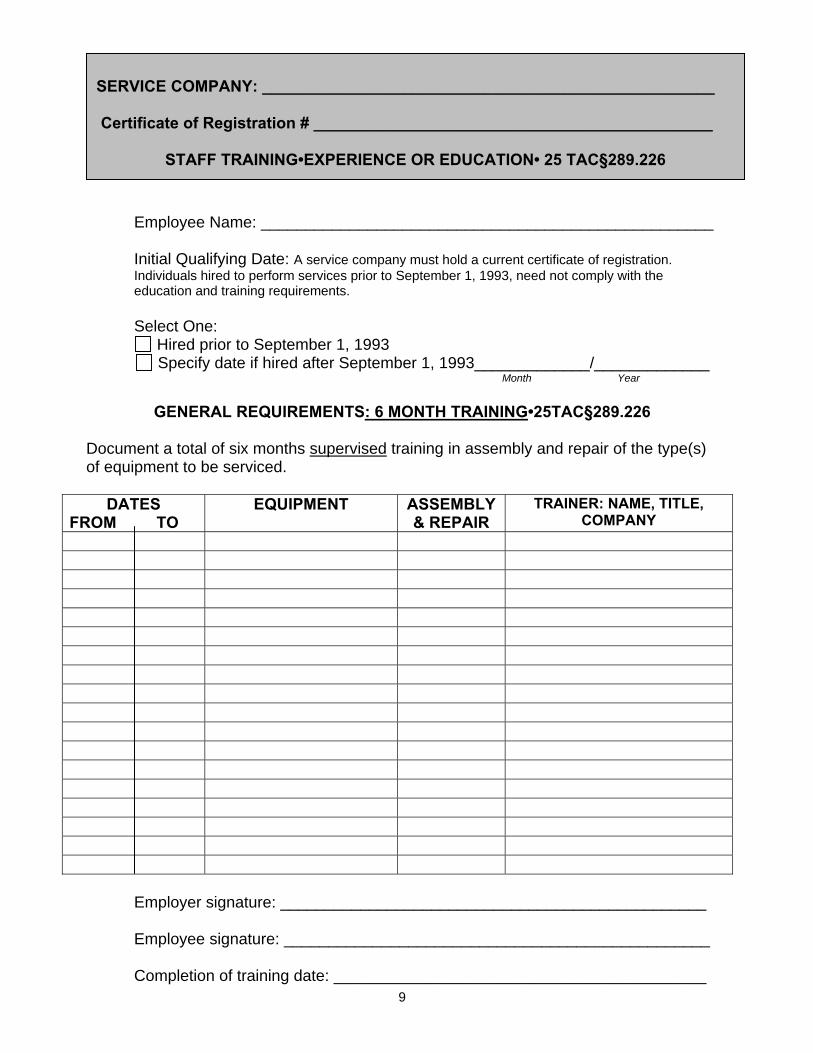
Employee Name: ___________________________________________________ Initial Qualifying Date: A service company must hold a current certificate of registration. Individuals hired to perform services prior to September 1, 1993, need not comply with the education and training requirements. Select One:
Hired prior to September 1, 1993 Specify date if hired after September 1, 1993_____________/_____________
Month Year
GENERAL REQUIREMENTS: 6 MONTH TRAINING•25TAC§289.226 Document a total of six months supervised training in assembly and repair of the type(s) of equipment to be serviced.
DATES FROM TO
EQUIPMENT ASSEMBLY & REPAIR
TRAINER: NAME, TITLE, COMPANY
Employer signature: ________________________________________________
Employee signature: ________________________________________________ Completion of training date: __________________________________________
SERVICE COMPANY: ___________________________________________________
Certificate of Registration # _____________________________________________
STAFF TRAINING•EXPERIENCE OR EDUCATION• 25 TAC§289.226

10
Employee Name: ___________________________________________________ Initial Qualifying Date: A service company must hold a current certificate of registration. Individuals hired to perform services prior to September 1, 1993, need not comply with the education and training requirements. Select one:
Hired prior to September 1, 1993 Specify date if hired after September 1, 1993_____________/_____________
Month Year
SPECIALIZED REQUIREMENTS: 25 TAC§289.226 All persons performing radiation machine assembly, installation or repair shall meet the general and one or more of the specialized requirements . ______________________________________has met the specialized requirements by: Check appropriate section and show documentation.
One year of formal training (may be satisfied by factory school, military technical training school, or other courses in radiation machine assembly, installation or repair techniques) or an associate's degree in biomedical equipment repair. 25 TAC§289.226
A bachelor's degree in electrical engineering with specialized training in radiation producing devices. 25 TAC §289.226
A combination of training and experience as noted above. 25 TAC §289.226 Employer signature: ________________________________________________ Employee signature: ________________________________________________
Date of signature: __________________________________________________
SERVICE COMPANY: ___________________________________________________
Certificate of Registration # ______________________________________________
STAFF TRAINING•EXPERIENCE OR EDUCATION• 25 TAC§289.226

11
IX. EPE TESTS REQUIRED BY RULE FOR RADIOGRAPHIC UNITS • The following is a list of required testing for radiographic units (except
fluoroscopic and CT systems). Formulas necessary for calculating the results and examples are supplied.
• All testing required will depend upon the regulations for the facility type and
modality used.
DENTAL VETERINARY GENERAL RADIOGRAPHY
Timer accuracy Exposure reproducibility kVp Tube stability Collimation a) intraoral - x-ray field size limitations 18 cm and above =7 cm < 18 cm = 6 cm b) PAN - x-ray field 0 inch misalignment horizontally – total of .5 inch vertically c) CEPH - x-ray field cannot exceed the image receptor by more than 2% of the SID SID-the means to limit >50 kVp = 18 cm 50 kVp = 10 cm Entrance exposure 60 kVp and above= 450 mR <60 kVp=600 mR
Timer accuracy kVp Collimation a) x-ray field must not exceed the image receptor by more than 2% of the SID b) center alignment SID – indicated and accurate within 2% Tube stability
Timer accuracy Exposure reproducibility kVp Tube stability Collimation a) field size indicator accuracy b) x-ray vs. light field congruence c) center alignment SID – indicated and accurate within 2% Linearity Entrance exposure (protocol and testing established and approved by a LMP)
X. X-RAY UNIT IDENTIFICATION ON THE EPE FORM MUST INCLUDE:
a) name of manufacturer; b) model and serial number taken from the CONTROL PANEL; c) location/room number where the x-ray unit is installed; and d) for portable/mobile systems identify the location where the x-ray unit is stored.
12
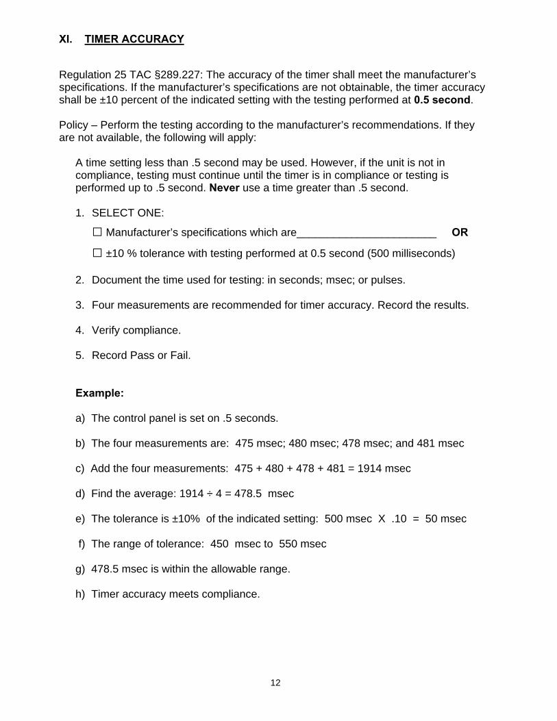
XI. TIMER ACCURACY
Regulation 25 TAC §289.227: The accuracy of the timer shall meet the manufacturer’s specifications. If the manufacturer’s specifications are not obtainable, the timer accuracy shall be ±10 percent of the indicated setting with the testing performed at 0.5 second. Policy – Perform the testing according to the manufacturer’s recommendations. If they are not available, the following will apply:
A time setting less than .5 second may be used. However, if the unit is not in compliance, testing must continue until the timer is in compliance or testing is performed up to .5 second. Never use a time greater than .5 second.
1. SELECT ONE:
□ Manufacturer’s specifications which are_______________________ OR
□ ±10 % tolerance with testing performed at 0.5 second (500 milliseconds)
2. Document the time used for testing: in seconds; msec; or pulses.
3. Four measurements are recommended for timer accuracy. Record the results. 4. Verify compliance.
5. Record Pass or Fail.
Example: a) The control panel is set on .5 seconds. b) The four measurements are: 475 msec; 480 msec; 478 msec; and 481 msec c) Add the four measurements: 475 + 480 + 478 + 481 = 1914 msec d) Find the average: 1914 ÷ 4 = 478.5 msec e) The tolerance is ±10% of the indicated setting: 500 msec X .10 = 50 msec f) The range of tolerance: 450 msec to 550 msec g) 478.5 msec is within the allowable range. h) Timer accuracy meets compliance.
13
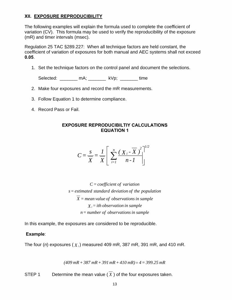
XII. EXPOSURE REPRODUCIBILITY
The following examples will explain the formula used to complete the coefficient of variation (CV). This formula may be used to verify the reproducibility of the exposure (mR) and timer intervals (msec). Regulation 25 TAC §289.227: When all technique factors are held constant, the coefficient of variation of exposures for both manual and AEC systems shall not exceed 0.05.
1. Set the technique factors on the control panel and document the selections. Selected: _______ mA; _______ kVp; _______ time
2. Make four exposures and record the mR measurements. 3. Follow Equation 1 to determine compliance.
4. Record Pass or Fail.
EXPOSURE REPRODUCIBILTIY CALCULATIONS EQUATION 1
samplein nsobservatio of number = n samplein nobservatio ith = X
samplein nsobservatio of value mean = X
population the of deviation standardestimated = svariation of tcoefficien = C
i
In this example, the exposures are considered to be reproducible. Example: The four (n) exposures ( X i ) measured 409 mR, 387 mR, 391 mR, and 410 mR.
STEP 1 Determine the mean value ( X ) of the four exposures taken.
⎥⎥⎦
⎤
⎢⎢⎣
⎡∑ 1-n
)X - X( X1 =
Xs = C i
2n
=1i
1/2
mR 399.25 = 4 mR) 410 + mR 391 + mR 387 + mR (409 ÷
14
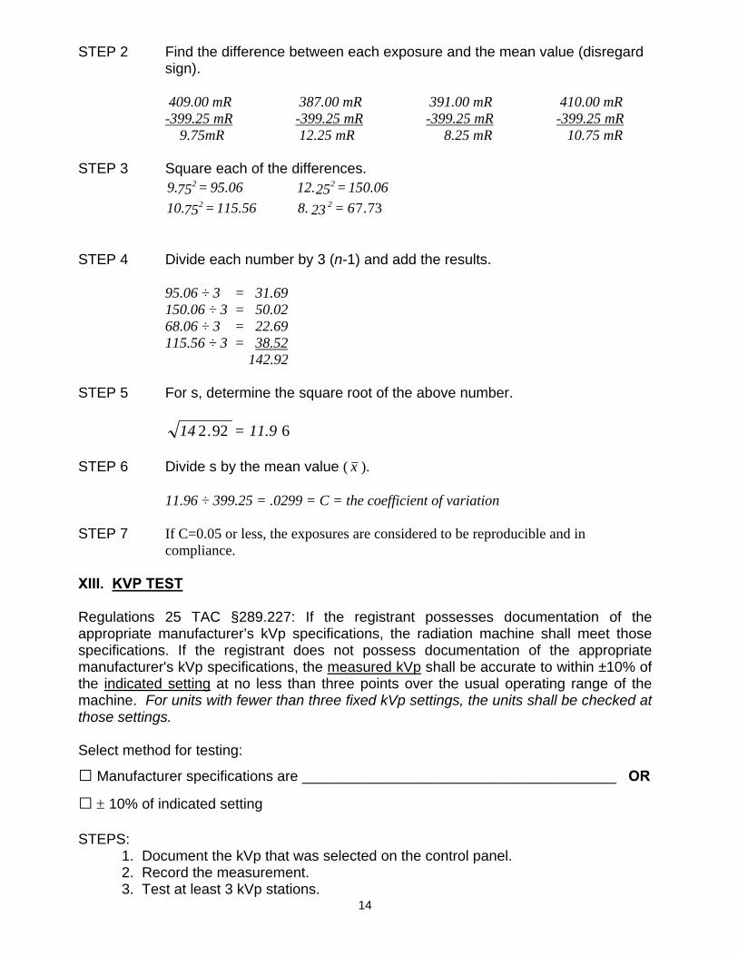
STEP 2 Find the difference between each exposure and the mean value (disregard sign).
409.00 mR 387.00 mR 391.00 mR 410.00 mR -399.25 mR -399.25 mR -399.25 mR -399.25 mR 9.75mR 12.25 mR 8.25 mR 10.75 mR
STEP 3 Square each of the differences.
95.06 = 759. 2 150.06 = 2512. 2 115.56 = 7510. 2 737.6 = 238. 2
STEP 4 Divide each number by 3 (n-1) and add the results.
95.06 ÷ 3 = 31.69 150.06 ÷ 3 = 50.02 68.06 ÷ 3 = 22.69 115.56 ÷ 3 = 38.52
142.92 STEP 5 For s, determine the square root of the above number.
6922 11.9 = .14 STEP 6 Divide s by the mean value ( x ).
11.96 ÷ 399.25 = .0299 = C = the coefficient of variation STEP 7 If C=0.05 or less, the exposures are considered to be reproducible and in
compliance. XIII. KVP TEST
Regulations 25 TAC §289.227: If the registrant possesses documentation of the appropriate manufacturer’s kVp specifications, the radiation machine shall meet those specifications. If the registrant does not possess documentation of the appropriate manufacturer's kVp specifications, the measured kVp shall be accurate to within ±10% of the indicated setting at no less than three points over the usual operating range of the machine. For units with fewer than three fixed kVp settings, the units shall be checked at those settings. Select method for testing:
□ Manufacturer specifications are _______________________________________ OR
□ ± 10% of indicated setting STEPS:
1. Document the kVp that was selected on the control panel. 2. Record the measurement. 3. Test at least 3 kVp stations.

15
4. If there are only 2 stations, test both. 5. Determine the percent of deviation.
6. Record Pass or Fail. EXAMPLE: [(Measured kVp – Indicated kVp) ÷ Indicated kVp) x 100] = % of Deviation
a) 70 kVp station is selected. b) 68 kVp is measured.
70 kVp - 68 kVp = 2
2 ÷ 70 = .03 .03 x 100 = 3% The unit is in compliance.
XIV. TUBE STABILITY
Regulation 25 TAC §289.227: The tube shall remain physically stable during exposures. In cases where tubes are designed to move during exposure, the registrant shall assure proper and free movement of the unit. STEPS:
1. Test the tube in all orientations. a) Check that locking devices are secure. b) Verify that the tube remains in position with no drifting.
2. If applicable, verify free movement where designed.
3. Record Pass or Fail.
XV. COLLIMATION
A. POINTS TO REMEMBER There are four areas to test when verifying collimation, however, the rules differ for the various modalities.
a. the source to image distance (SID) b. accuracy of the field size indicators c. alignment of the x-ray field and the light field size d. center alignment
XV. COLLIMATION B. DETERMINING THE PROJECTED FIELD SIZE WHEN ONLY ONE
SIZE CASSETTE IS AVAILABLE
a. A direct measurement may be used if a fluorescent screen is available.
16
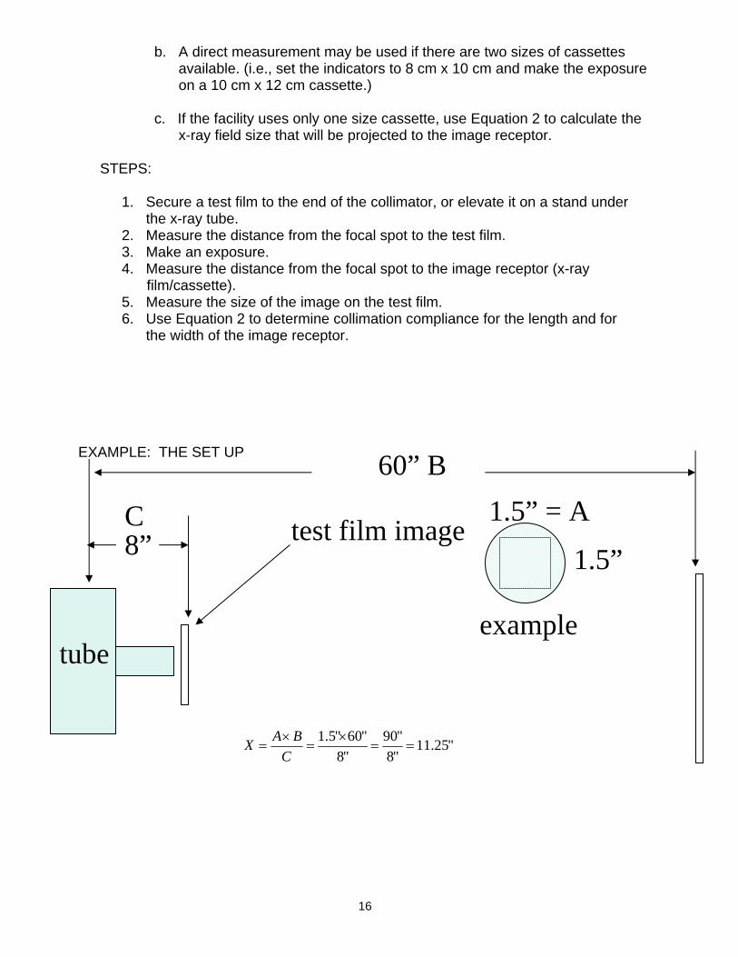
b. A direct measurement may be used if there are two sizes of cassettes available. (i.e., set the indicators to 8 cm x 10 cm and make the exposure on a 10 cm x 12 cm cassette.)
c. If the facility uses only one size cassette, use Equation 2 to calculate the x-ray field size that will be projected to the image receptor.
STEPS:
1. Secure a test film to the end of the collimator, or elevate it on a stand under the x-ray tube. 2. Measure the distance from the focal spot to the test film. 3. Make an exposure. 4. Measure the distance from the focal spot to the image receptor (x-ray
film/cassette). 5. Measure the size of the image on the test film. 6. Use Equation 2 to determine collimation compliance for the length and for
the width of the image receptor.
EXAMPLE: THE SET UP
8”
60” B
tube
test film image 1.5” = A
1.5” C
"25.11"8"90
"8"60"5.1
==×
=×
=C
BAX
example

17
COLLIMATION Equation 2
CALCULATIONS TO DETERMINE PROJECTED FIELD SIZE AT SID
Where:
EXAMPLE The indicated field size was 14 in. by 17 in. The SID was indicated to be 40 in., the test film location was measured to be 12 in. from the focal spot, and the field size measured on the test film was measured to be 3.5 in. by 4.3 in. Is the misalignment greater than 2%? STEP 1 Multiply each test film field size dimension by the SID.
STEP 2 Divide each number determined in step 1 by the distance from the focal
spot to the test film.
STEP 3 Find the difference between the selected field size and the measured field
size determined in step 2. This is the misalignment.
STEP 4 Calculate 2% of the SID (3% for automatic collimation and fluoro) to
determine the allowed misalignment.
40 inches x 0.02 = 0.8 inches
X = C
B x A
SIDthe at sizeField = Xfilm test the to spotfocal the from distance = C
SID= Bfilm test the on determined sizefield = A
172 = 40 x 4.3140 = 40 x 3.5
14.3 = 12
172
11.6 = 12
140
14.0 - 11.6 = 2.4 17.0 - 14.3 = 2.7
18
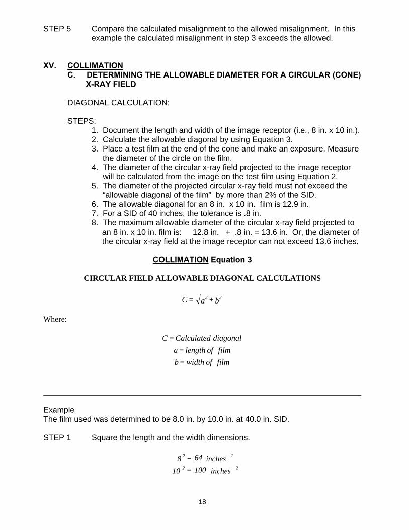
STEP 5 Compare the calculated misalignment to the allowed misalignment. In this example the calculated misalignment in step 3 exceeds the allowed.
XV. COLLIMATION
C. DETERMINING THE ALLOWABLE DIAMETER FOR A CIRCULAR (CONE) X-RAY FIELD
DIAGONAL CALCULATION:
STEPS: 1. Document the length and width of the image receptor (i.e., 8 in. x 10 in.). 2. Calculate the allowable diagonal by using Equation 3. 3. Place a test film at the end of the cone and make an exposure. Measure the diameter of the circle on the film. 4. The diameter of the circular x-ray field projected to the image receptor will be calculated from the image on the test film using Equation 2. 5. The diameter of the projected circular x-ray field must not exceed the
“allowable diagonal of the film” by more than 2% of the SID. 6. The allowable diagonal for an 8 in. x 10 in. film is 12.9 in. 7. For a SID of 40 inches, the tolerance is .8 in. 8. The maximum allowable diameter of the circular x-ray field projected to
an 8 in. x 10 in. film is: 12.8 in. + .8 in. = 13.6 in. Or, the diameter of the circular x-ray field at the image receptor can not exceed 13.6 inches.
COLLIMATION Equation 3
CIRCULAR FIELD ALLOWABLE DIAGONAL CALCULATIONS
Where:
Example The film used was determined to be 8.0 in. by 10.0 in. at 40.0 in. SID. STEP 1 Square the length and the width dimensions.
b + a = C 22
film of width= bfilm of length = a
diagonal Calculated = C
inches 100 = 10inches 64 = 8
22
22

19
STEP 2 Add the two numbers determined in step 1.
STEP 3 Find the square root of the number determined in step 2.
STEP 4 Determine 2% of the SID
STEP 5 To determine the allowable diagonal (diameter of the circular field) add the number determined in step 3 to the number determined in step 4.
STEP 6 Compare the allowable diagonal with the measured field size from the
collimation test. XV. COLLIMATION
D. DENTAL INTRAORAL UNITS
Regulations 25 TAC §289.232
• If the SSD is 18 cm or more, the x-ray field must be restricted to no more than 7 cm.
• If the SSD is less than 18 cm, the field must be limited to no more than 6 cm.
STEPS: 1. Do not measure the extension cone and record as the x-ray field size. The cone is not always the collimating device. It is used to assure the proper SID. 2. Make an exposure on a piece of film or a fluorescent screen that is placed at the end of the extension cone. 3. Measure the size of the x-ray field. 4. Determine compliance with the rule. 5. Record Pass or Fail.
inches 164 = inches 100 + inches 64 222
inches 12.8 = inches 164 2
inches 0.8 = 0.02 x inches 40
inches 13.6 = inches 0.8 + inches 12.8

20
XV. COLLIMATION E. DENTAL EXTRAORAL UNITS
CEPHALOMETRIC UNITS Regulations 25 TAC §289.232 • The x-ray field must not exceed the image receptor (x-ray film/cassette) by
more than 2% of the source to image distance (SID) for the length and width of a rectangular receptor.
• The x-ray field must not exceed 2% of the SID for the diagonal of the receptor when circular or polygon collimation is used. (Collimation Equation 3)
• Verify compliance by using a fluorescent screen or Collimation Equation 2.
PANORAMIC UNITS Regulations 25 TAC §289.232 • The x-ray field must be restricted to the image slit in the transverse axis. • The x-ray field may not exceed the slit in the vertical axis by more than a total
of .5 inch. STEPS: 1. Determine the x-ray field alignment within the image slit. 2. When the beam is contained within the slit it is acceptable to record
0 in. x 0 in. misalignment even if the beam is misaligned within the slit. 3. When the beam extends above and below the slit, measure the misalignments, add them both together, and determine compliance.
4. Remember: a) When documenting the x-ray field size, do not write the size of the x-ray film. Record the size of the x-ray beam within the slit.
b) Do not write the size of the image slit in the section on the EPE form where the misalignment of the x-ray field is to be recorded. 5. Record Pass or Fail.
DIGITAL UNITS: If the digital receptor does not have a physical image slit, consult the technical specifications section of the owner’s manual and find the dimension. Using a phosphor, or other means, insure the beam doesn’t exceed the slit beyond the limits. Always follow the alignment procedure in the installation manual.
EXAMPLE: .5 inch X-ray field Image Slit NO VIOLATION NO VIOLATION VIOLATION
21
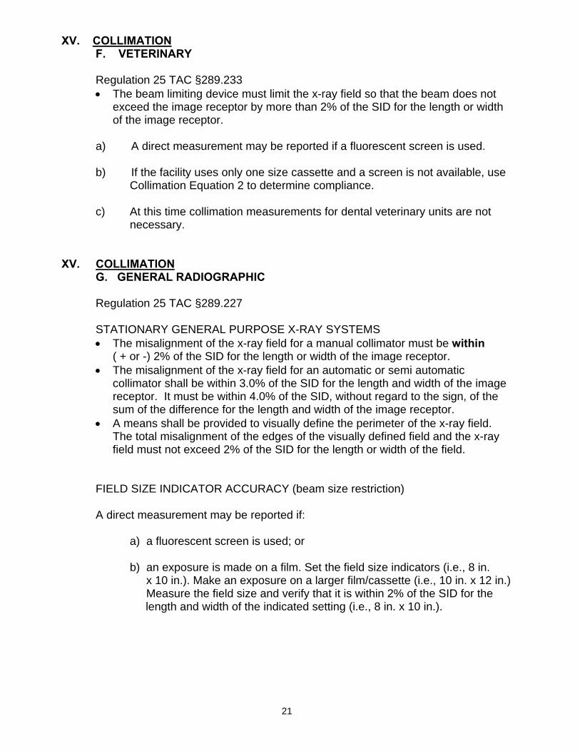
XV. COLLIMATION F. VETERINARY
Regulation 25 TAC §289.233 • The beam limiting device must limit the x-ray field so that the beam does not
exceed the image receptor by more than 2% of the SID for the length or width of the image receptor.
a) A direct measurement may be reported if a fluorescent screen is used.
b) If the facility uses only one size cassette and a screen is not available, use
Collimation Equation 2 to determine compliance.
c) At this time collimation measurements for dental veterinary units are not necessary.
XV. COLLIMATION
G. GENERAL RADIOGRAPHIC
Regulation 25 TAC §289.227
STATIONARY GENERAL PURPOSE X-RAY SYSTEMS • The misalignment of the x-ray field for a manual collimator must be within
( + or -) 2% of the SID for the length or width of the image receptor. • The misalignment of the x-ray field for an automatic or semi automatic
collimator shall be within 3.0% of the SID for the length and width of the image receptor. It must be within 4.0% of the SID, without regard to the sign, of the sum of the difference for the length and width of the image receptor.
• A means shall be provided to visually define the perimeter of the x-ray field. The total misalignment of the edges of the visually defined field and the x-ray field must not exceed 2% of the SID for the length or width of the field.
FIELD SIZE INDICATOR ACCURACY (beam size restriction)
A direct measurement may be reported if:
a) a fluorescent screen is used; or
b) an exposure is made on a film. Set the field size indicators (i.e., 8 in. x 10 in.). Make an exposure on a larger film/cassette (i.e., 10 in. x 12 in.) Measure the field size and verify that it is within 2% of the SID for the
length and width of the indicated setting (i.e., 8 in. x 10 in.).
22
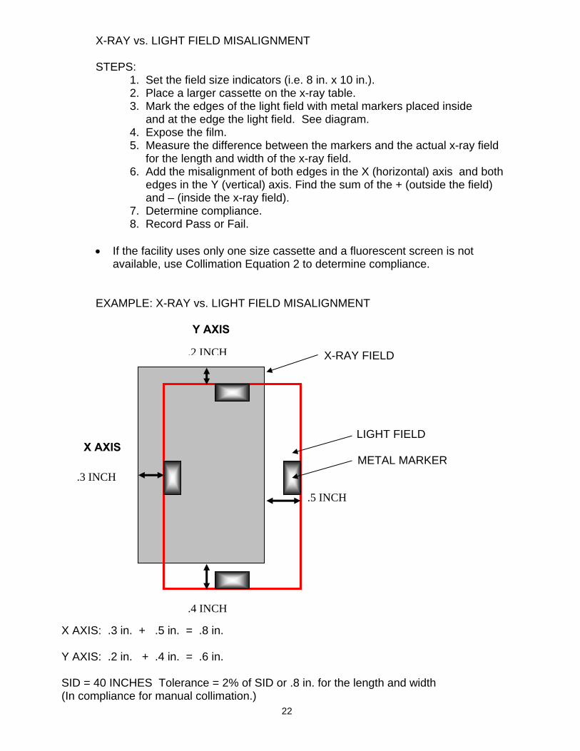
X-RAY vs. LIGHT FIELD MISALIGNMENT
STEPS: 1. Set the field size indicators (i.e. 8 in. x 10 in.). 2. Place a larger cassette on the x-ray table. 3. Mark the edges of the light field with metal markers placed inside and at the edge the light field. See diagram. 4. Expose the film. 5. Measure the difference between the markers and the actual x-ray field for the length and width of the x-ray field. 6. Add the misalignment of both edges in the X (horizontal) axis and both edges in the Y (vertical) axis. Find the sum of the + (outside the field) and – (inside the x-ray field). 7. Determine compliance.
8. Record Pass or Fail.
• If the facility uses only one size cassette and a fluorescent screen is not available, use Collimation Equation 2 to determine compliance.
EXAMPLE: X-RAY vs. LIGHT FIELD MISALIGNMENT Y AXIS X-RAY FIELD LIGHT FIELD X AXIS METAL MARKER X AXIS: .3 in. + .5 in. = .8 in. Y AXIS: .2 in. + .4 in. = .6 in. SID = 40 INCHES Tolerance = 2% of SID or .8 in. for the length and width (In compliance for manual collimation.)
.3 INCH
.4 INCH
.5 INCH
.2 INCH

23
XVI. SOURCE TO IMAGE DISTANCE (SID)
DENTAL SYSTEMS: Regulations 25 TAC §289.232 • For use with intraoral image receptors the SSD cannot be less than 18 cm when above 50 kVp is used. • For use with intraoral image receptors the SSD cannot be less than 10 cm if 50
kVp or below is used.
GENERAL RADIOGRAPHIC SYSTEMS (Human use): Regulations 25 TAC §289.227 • A numerical SID indicator must be present and accurate to within 2% of the
SID.
The following is applicable based on manufacturer’s design: a) PORTABLE X-RAY SYSTEMS: A numerical SID indicator must be present and accurate to within 2% of the SID.
b) SPECIAL PURPOSE SYSTEMS: The SID must be reported. (A special purpose system is one designed for only one body part radiographs). c) All portable or mobile radiographic systems must be provided with means to limit the source to skin distance to equal to or greater than 30 cm.
If the SID indicator is a tape measure, pointer, converging laser, etc. report the indicated SID used, verify the accuracy, and document both. Do not report NA; if there is no misalignment report 0.
VETERINARY SYSTEMS: Regulations 25 TAC §289.233: • A numerical SID indicator must be present and accurate to within 2% of the
SID.
VETERINARY PORTABLE SYSTEMS: Should comply with the human use requirements as applicable based on manufacturer’s design.
XVII. CENTER ALIGNMENT
DENTAL SYSTEMS: Center alignment is not reported.
GENERAL RADIOGRAPHIC SYSTEMS (human use): Regulations 25 TAC§289.227: • The center of the x-ray field, when perpendicular to the image receptor, must be centered to the image receptor to within 2% of the SID.
VETERINARY: Regulations 25 TAC §289.233: • A means must be provided to center the primary beam to the image receptor
within 2% of the SID.

24
The following is applicable based on manufacturer’s design:
a) PORTABLE X-RAY SYSTEMS: A means shall be provided to align the center of the x-ray field to the image receptor within 2% of the SID. b) SPECIAL PURPOSE X-RAY SYSTEMS: A means shall be provided to
align the center of the x-ray field to the center of the image receptor to within 2% of the SID.
XVIII. LINEARITY DENTAL and VETERINARY
• Linearity is not verified on EPEs for Veterinary or Dental systems.
GENERAL RADIOGRAPHIC SYSTEMS (human use): • The average ratios of exposure mR to the indicated mAs product obtained at
any two consecutive mA or mAs settings shall not differ by more than 0.10 times their sum, where X1 and X2 are the average mR/mAs values obtained at each of two consecutive tube current.
STEPS: 1. Use two consecutive mA or mAs stations for measurements.
2. Choose the same focal spot size; preferably the large focal spot. 3. The four exposures made for the reproducibility test measurements may be used to determine X1.
4. Make two additional exposures on the adjacent mA or mAs station. 5. Follow Equation 4 for calculations. 6. Record Pass or Fail.
LINEARITY CALCULATIONS
EQUATION 4
Where:
_______________________________________________________________________________
)X+ X.1( X - X 2121 ≤
testlinearity the for used mAs = mAsexposuresility reproducib for used mAs = mAs
exposureslinearity two the of average the = E
exposuresility reproducib four the of average the = EmAsE = X
mAsE = X
2
1
2avg
1avg
2
2avg2
1
1avg1
25
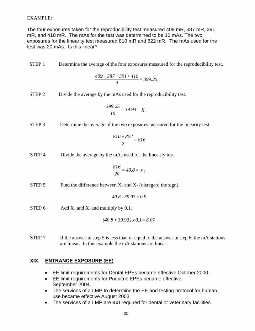
EXAMPLE: The four exposures taken for the reproducibility test measured 409 mR, 387 mR, 391 mR, and 410 mR. The mAs for the test was determined to be 10 mAs. The two exposures for the linearity test measured 810 mR and 822 mR. The mAs used for the test was 20 mAs. Is this linear? STEP 1 Determine the average of the four exposures measured for the reproducibility test.
STEP 2 Divide the average by the mAs used for the reproducibility test.
STEP 3 Determine the average of the two exposures measured for the linearity test.
STEP 4 Divide the average by the mAs used for the linearity test.
STEP 5 Find the difference between X1 and X2 (disregard the sign).
STEP 6 Add X1 and X2 and multiply by 0.1.
STEP 7 If the answer in step 5 is less than or equal to the answer in step 6, the mA stations are linear. In this example the mA stations are linear. XIX. ENTRANCE EXPOSURE (EE)
• EE limit requirements for Dental EPEs became effective October 2000. • EE limit requirements for Podiatric EPEs became effective
September 2004. • The services of a LMP to determine the EE and testing protocol for human
use became effective August 2003. • The services of a LMP are not required for dental or veterinary facilities.
399.25 = 4
410+391+387+409
X = 39.93 = 10
399.251
816 = 2
822 + 810
X = 40.8 = 20
8162
0.9 = 39.93 - 40.8
8.07 = 0.1 x )39.9 + (40.8 3

26
VETERINARY EE LIMITS: EE limits are NOT regulated. GENERAL RADIOGRAPHIC EE LIMITS – HUMAN USE:
• A LMP must establish the protocol for testing, calculate the EE, and sign the report.
• The following is a list of EE requirements:
Examination Patient Thickness(cm)
Exposure Limit (mR)
Chest-PA
Non-Grid 23 20 Grid 23 30 Abdomen KUB
23
450
Lumbo-Sacral Spine–AP
23
550
Thoracic Spine
23
325
Cervical Spine
13
120
Full Spine
23
300
Skull-Lateral
15
150
Foot-DP
8
50
DENTAL EE LIMITS: • EE is limited to a dose of 450 mR for dental intraoral bite wing examinations
at 60 kVp and above. • EE is limited to a dose of 600 mR for dental intraoral bite wing examinations
at less than 60 kVp.
REMINDERS: a) Only the dose for intraoral bitewing examinations are regulated. b) At this point it is not necessary to measure the dose received on
panoramic or cephalometric units. c) Set the control panel with the kVp, time, and mA that the facility uses for an intraoral bite wing examination on an average sized patient. d) Determine if the EE will be calculated or a direct measurement made. e) Follow the instructions listed. f) Determine compliance. g) Record Pass or Fail.
DENTAL ENTRANCE EXPOSURE (EE) CALCULATIONS
The entrance exposure is a measurement of the radiation dose in millirem, received at the patient’s cheek during the exposure.
• If the dosimetey system used has an ion chamber on a cable, a direct measurement may be made.
• If the dosimetey system has an ion chamber built into a housing, the EE must be calculated.
27
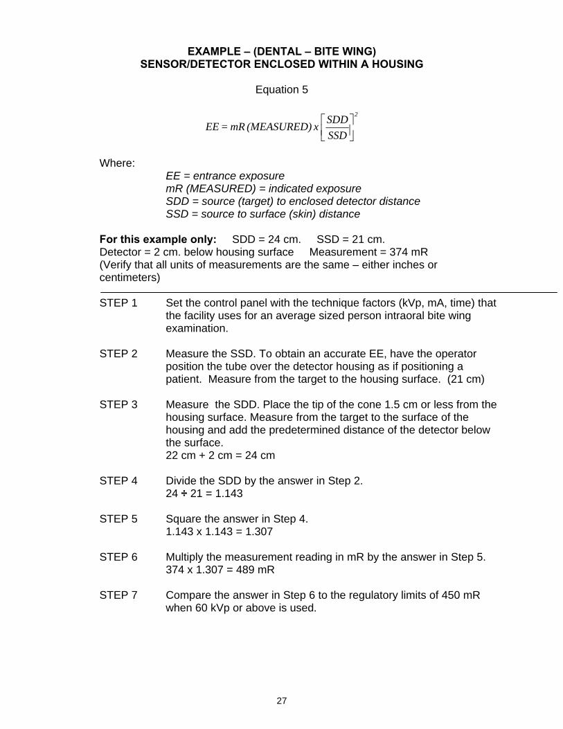
EXAMPLE – (DENTAL – BITE WING) SENSOR/DETECTOR ENCLOSED WITHIN A HOUSING
Equation 5
⎥⎦⎤
⎢⎣⎡
SSDSDD x (MEASURED) mR = EE
2
Where:
EE = entrance exposure mR (MEASURED) = indicated exposure SDD = source (target) to enclosed detector distance SSD = source to surface (skin) distance
For this example only: SDD = 24 cm. SSD = 21 cm. Detector = 2 cm. below housing surface Measurement = 374 mR (Verify that all units of measurements are the same – either inches or centimeters)
STEP 1 Set the control panel with the technique factors (kVp, mA, time) that
the facility uses for an average sized person intraoral bite wing examination.
STEP 2 Measure the SSD. To obtain an accurate EE, have the operator
position the tube over the detector housing as if positioning a patient. Measure from the target to the housing surface. (21 cm)
STEP 3 Measure the SDD. Place the tip of the cone 1.5 cm or less from the
housing surface. Measure from the target to the surface of the housing and add the predetermined distance of the detector below the surface. 22 cm + 2 cm = 24 cm
STEP 4 Divide the SDD by the answer in Step 2.
24 ÷ 21 = 1.143
STEP 5 Square the answer in Step 4. 1.143 x 1.143 = 1.307
STEP 6 Multiply the measurement reading in mR by the answer in Step 5. 374 x 1.307 = 489 mR
STEP 7 Compare the answer in Step 6 to the regulatory limits of 450 mR when 60 kVp or above is used.

28
NOTES:


![[XLS]LBSWnonClinical - Texas Department of State …dshs.texas.gov/socialwork/Excel/LBSWnonClinical.xls · Web viewCADENA, CUAUHTEMOC CALDERON, ARTURO CALDWELL, THRESA ANNETTE CALVILLO,](https://img.pdfslide.us/doc/110x75/5bc48cb809d3f274118c1b92/xlslbswnonclinical-texas-department-of-state-dshstexasgovsocialworkexcel.jpg)

![XSC Single Fiber series - XENYAsup.xenya.si/sup/info/xenya/wdm/[XWDM]_XSC_Series_Datasheet_D3.pdf · 2 XSC Single Fiber CWDM Series XSC1‐ 111202173900 exhibits watermark peak attenuation,](https://img.pdfslide.us/doc/110x75/5eb942b1648ed51caa7dd420/xsc-single-fiber-series-xwdmxscseriesdatasheetd3pdf-2-xsc-single-fiber.jpg)