Embed Size (px)
Citation preview

UNIVERSITY OF BENIN
Benin City, Nigeria
Training Course 2
BOREHOLE CONSTRUCTION AND MAINTENANCE
Module 1: Introduction and Current Challenges of Groundwater Management Module 2: Wells Module 3: Well Construction Procedures Module 4: Water Sampling and Analysis Module 5: Well Operation and Maintenance
MODULE 1: Introduction and Current Challenges of Groundwater Management
1.0 Introduction Boreholes are effective ways of tapping into the water bearing aquifer below the ground and
pumping the water to the surface. Boreholes for extracting water consist essentially of a
vertically drilled shaft, a strong lining (casing) to prevent collapse of the walls, which includes
a means of allowing clean water to enter the borehole space (screen), surface protection, and a
means of extracting water. The exploitation of ground water is a complicated process which
involves sinking a narrow shaft into the ground to reach the aquifer by using a drilling rig.
Failure is sometimes experienced when carrying out borehole drilling operations or when using
installed borehole systems. These failures are caused by several complications which may arise
from poor maintenance and rehabilitation of boreholes, lack of expertise poor choice of
technology, and poor supervision of the drilling project In order to prevent these complications,
the following measures must be taken: proper maintenance and rehabilitation of bore hole,
proper pump installation and maintenance, proper supervision of borehole projects, the use of
appropriate drilling technology and the standardization of borehole design and drilling process.
1.1 Current Challenges of Groundwater Management:
The demand for groundwater is likely to increase in the future, the main reason being increased
water use globally. Another reason may be the need to offset declining surface water availability
due to increasing temperature and decreasing precipitation and variability. The ever-increasing
demands along with natural stressors result into major challenges
for management of the vital natural resource in the country. Increasing population
is the major challenge where groundwater is the main source of safe water for drinking and
domestic purposes in rural and urban areas. Meeting the demand for increasing food production
is another major challenge for the world’s most densely populated country. Significant increase
in dry season rice production through groundwater irrigation has made the country self-
sufficient in rice, and production of all major crops has also increased. Demand for water is
also increasing due to faster rate of urbanization and industrializations; groundwater is the
major source of supply of municipal and industrial waters. The scenario of too much and too
little surface water compels to use more and more groundwater all over the country, and large
groundwater is fresh and free from pathogenic contaminants over most of the country, and
switching to this source for drinking saved millions of lives over the year.

Occurrences of natural arsenic and salinity are the two most severe water quality issues of the
current time. Millions of people are still drinking arsenic above national and international
standards, whereas people living in the coastal areas are exposed to high salinity. Also, pollution
of groundwater due to municipal, agricultural and industrial sources is becoming widespread.
People living in the slums in the big cities and adjacent to industrial towns suffer from safe
water scarcity. Groundwater abstraction is increasing every day without a proper management
and monitoring plan. Conventional water pumps are becoming inoperative in many areas due
to declining water levels and need to be replaced by alternative expensive pumping
technologies. Groundwater governance is almost nonexistence in the country due to mainly
lack of proper institutional arrangements. There are rules, regulations and policies to ensure
proper management, but enforcement is lacking
1.2.0 Well Siting. Testing and Sampling
1.2.1 Site Selection.
Locating test bores and wells (and eventually water wells), if based
on technical criteria rather than convenience alone, begins with a site selection process
before drilling or testing is planned. The goal should be pre-selection of the best possible
sites, and anticipation of both technical and other practical problems (e.g., neighbouring
wells). This decision-making process involves a combination of hydrogeological
advisors, regulatory personnel, well drilling contractors, engineers, and the property
owners involved. Tools include maps, aerial photographs, well logs and other relevant
file information from the area, and site inspection.
1.2.2 Well Site Selection Criteria The six potential well site selection criteria are as follows:
I. Groundwater production potential or yield
II. Groundwater quality, water quality;
III. Vulnerability to known or suspected contamination or natural risks such as
IV. Regulated distance from potential contaminant sources (e.g., septic tanks; oil
V. Potential for interference with other existing production wells, surface water flows, or
VI. Potential for interference with utilities
Potential drilling sites being analyzed as potential water well sites should have some
reasonable expectation of providing sufficient, potable water; meet regulatory
requirements; and not pose unacceptable health or safety risks to workers or future water
users. For public water supply wells, will the location allow for a defensible wellhead
protection area that does not include multiple potential pollution sources environmentally
important water uses (e.g., wetlands or springs) or areas;
1.2.3 Test Borehole and Well Drilling.
The purpose of drilling a test hole is to obtain information on ground water quality and
formation materials, and to help establish essential "ground truth" at a specified location,
including: formations;
(1) The depth and extent of the water-bearing formations, or zones within
(2) Thickness, nature, and areal extent of confining layers;
(3) Existence of specific features of note (oily or sand seams)

(4) Water quality and actual yield and drawdown information. Location of test holes should be based on the objectives of the drilling project, and should
be selected based on available geologic information. For example, a test hole drilled to
test a location for municipal water supply would be selected for maximum
uncontaminated production. Test holes to coder the location of a contaminant plume
would be located based on existing knowledge of the plume and other field information
such as geophysical survey results. For a borehole to characterize a water-bearing fracture
zone would be located based on maps, and aerial and geophysical surveys
1.2.4 Drilling Logs and Reports
Drilling logs and other records of the test hole are critically important for later
evaluation in planning production wells. They may be the only site-specific geologic
information available for a property or even the local area. Well drillers and geologists
must prepare and keep complete logs setting for critical hydrogeological information,
including: Descriptions of drilling methods;
(1) The reference point for all depth measurements;
(2) The depth at which each change of formation occurs;
(3) The depth at which the first water was encountered;
(4) The depth at which each stratum was encountered;
(5) The thickness of each stratum;
(6) The identification of the material of which each stratum is composed and its
(7) Depths of major fractures or other features (e.g., oily seams);
(8) The depth interval from which each water and formation sample was taken;
(9) The depth at which hole diameters (bit sizes) change.
(10) The depth to the static water level (SWL) and changes in SWL with
(1 1) Total depth of completed well;
(12) Any and all other pertinent information for a complete and accurate log, eg.,
temperature, pH, appearance (colour), or odour of any water samples taken;
(1 3) Depth or location of any lost drilling fluids, drilling materials or tools;
(1 4) The depth and material used for the surface seal, if applicable;
(1 5) The nominal hole diameter of the well bore above and below casing seal;
(16) The amount of cement (number of sacks) installed for the seal, if applicable;
(1 7) The depth and description of the well casing;

(1 8) The description (to include length, diameter, slot sizes, material, and
manufacturer) and location of well screens, or number, size and location of perforations;
(1 9) The sealing off of water-bearing strata, if any, and the exact location thereof.
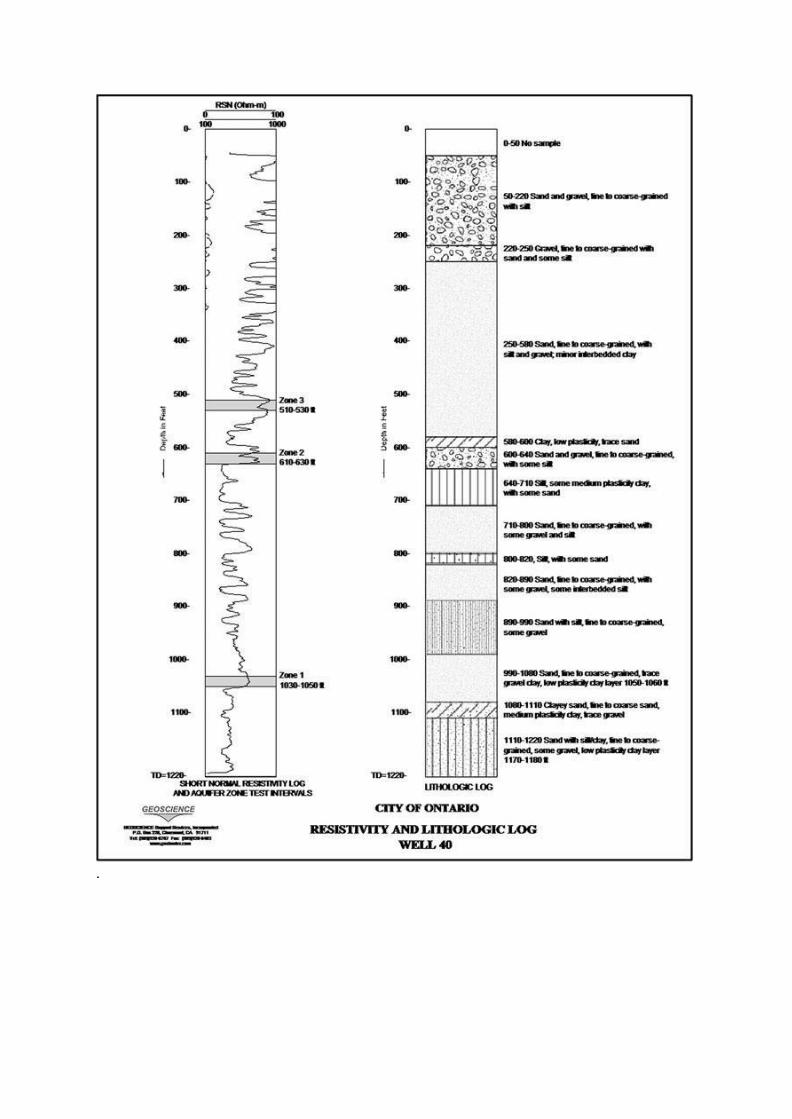
1.2.5 Sample Report of Geophysical Investigation For A Borehole
1. The geophysical survey was commissioned for the hydro geophysical characteristic of the
subsurface layers within the location of interest with a view to identifying location that could
be drilled for a productive borehole.
2. The Pre-drilling surveys aimed at delineating the several geologic units beneath the surface
of the area and determining the suitability of drilling productive borehole within and outside
the compound were carried out.
3. Two locations were surveyed based on the Constant Separation Traverse were selected for
detailed investigations of the hydrogeological characteristics of the subsurface layers using
the Schlumberger Array of Vertical Electrical Sounding (VES) study.
4. The area is characterized by the presence of clayey overburden and fresh basement rocks
occurring at varying depth
5. Based on the interpretation of the VES data, it is not advisable to drill a borehole within the
compound.

Figure 1. Dual spaced and 4p density logs in a cased monitoring well showing completion as
interpreted from the logs
The Geophysical Survey was aimed at the following:
a. Delineating the several geologic units beneath the surface of the area
b. Ascertaining their hydro-geologic significance of these units.
c. Determining the suitability of drilling a productive borehole at the points investigated
d. Making appropriate recommendation, if any, to ensure the success of the boreholes Inc.)
.
MODULE 2: TYPES OF WELLS
Wells are generally classified according to their type of construction as follows:
• Dug wells
• Bored wells
• Driven wells
• Jetted wells
• Drilled wells
2.1.1 Dug Wells
A dug well can furnish large quantities of water from shallow groundwater sources. Dug
wells are uncommon because of the cost to install them and the potential for contamination
of the shallow aquifers and the wells themselves. Small-diameter wells can be constructed
manually with pick and shovel; larger wells are constructed with machinery such
as a clamshell bucket if the soil conditions are suitable.
2.1.2 Bored Wells
Wells can be constructed quickly by boring where the geologic formation types are suitable.
The formation must be soft enough for an auger to penetrate yet firm enough so it
will not cave in before a liner can be installed. The most suitable formations for bored
wells are glacial till and alluvial valley deposits.
A bored well is constructed by driving an auger into the earth. Bored wells are limited
to approximately 3 ft (1 m) in diameter and depths of 25 to 60 ft (8 to 18 m) under suitable
conditions. As the auger penetrates, extensions are added to the drive shaft. A casing is
forced into the hole as material is removed until the water-bearing strata are reached.
Installing well screens or a perforated casing in the water-bearing sand and gravel layer
completes the well.
2.1.3 Driven Wells
Driven wells are simple to install; however, they are practical only when the water-bearing
formations are relatively close to the surface and no boulders or bedrock exist in the soil
or other formations between the surface and the aquifer. These wells consist of a pointed
well screen, called a drive point, and lengths of pipe attached to the point. The point has a
steel tip that enables it to be pounded through some gravel or hardpan (a hard layer of
cemented soil near the ground surface) to the water-bearing formation (Figure 2-10).
The diameter of the well pipe varies from as small as 1 in. (32 mm) up to 4 in. (107 mm).
The maximum depth that can be achieved is generally 30 to 40 ft (9 to 12 m).
2.1.4 Jetted Wells
A jetting pipe, which is equipped with a cutting knife on the bottom, is used to construct
jetted wells. Water is pumped down the pipe and out of the drill bit against the bottom of
the hole. The high-pressure water jet at the bottom of the pipe, in coordination with the
cutting knife, loosens and removes the soil beneath the pipe and allows it to advance
downward.
The casing is usually sunk as the drilling progresses until it passes through the waterbearing
formation. The well screen connected to a smaller-diameter pipe is then lowered
into the casing, and the outer casing is withdrawn to expose the screen to the formation.
These wells are generally suited to sandy formations and cannot be constructed by jetting
through clay or hardpan or where there are boulders in the formation
2.1.5 Drilled Wells
Drilled wells are the most commonly used well type for public water supplies because they
can be installed in almost any situation. They can be constructed to extreme depths with
small or large well diameters (up to 4 ft [1.5 m] or possibly larger). They are also the most
common type of well drilled for oil extraction.
A drilled well is constructed using a drilling rig and casing. The rig makes the hole,
and casing is placed in the hole to prevent the walls from collapsing. Screens are installed
when water-bearing formations are encountered at one or more levels. The more commonly
used methods of drilling water supply wells are the following:
• Cable tool method
• Rotary hydraulic method
• Reverse-circulation rotary method
• California method
• Rotary air method
• Down-the-hole hammer method

DRILLING METHODS
Rotary
Percussion
Combination of Rotary
& Percussion Cable tool
Direct Circulatio
n
Reverse Circulatio
n Rotary CUM Cable Tool
Rotary cum DTH
Duel Rotary
Cased Hole
Open Hole
Figure 3: Typical borehole drilling showing water flow
Fig. 4 Different types of drilling methods
2.2.1 Cable tool method
The percussion drilling method, commonly referred to as the cable tool method, has been
used extensively for wells of all sizes and depths but has waned in popularity because faster
and easier methods have been developed. There are many commercial varieties of cable tool

rigs. The operating principle for all varieties is the same. They use a bit at the end of a cable
that is repeatedly raised and dropped to fracture the soil material. The drilling tool has a
clublike chisel edge that breaks the formation into small fragments. The reciprocating
motion of the drilling tool mixes the loosened material into a sludge like substance.
In each run of the drill, a depth of 3–6 ft (1–2 m) of the hole is drilled. The drill is then
pulled from the hole, and a bailer is used to remove the sludge. The bailer consists of a
section
of casing 10 to 25 ft (3 to 8 m) long, slightly smaller in diameter than the drilled hole and
having a check valve in the bottom. A casing is forced into the hole as soon as it is
necessary to prevent a cave-in of the walls.
2.2.2 Rotary hydraulic method
In the rotary method of well drilling, the hole is made by spinning a cylinder-shaped bit
on the bottom of multiple sections of drill pipe. The speed of rotation can be varied to
achieve the best cutting effectiveness for different types of soil and rock.
Drilling fluid (typically a thin slurry of clay and water, also called drilling mud) is
pumped down to the bit (Figure 2-13). The fluid flows out through holes in the bit, picks
up loosened material, and carries it up the borehole to the surface. The circulating fluid
also helps to cool the bit and keep the hole open during drilling. The fluid that flows to the
surface overflows from the well and is routed by a ditch into a settling pit or tub, where the
cuttings settle out.
2.2.3 Reverse-circulation rotary method
The reverse-circulation rotary method of drilling differs from the regular rotary method in
that the drilling fluid is circulated in the opposite direction. The advantage is that because
water is generally used as the drilling fluid, the method can be used where drilling additives
are undesirable. This method is also particularly well suited for constructing gravelpacked
wells, because the drilling fluid mixture used in the regular rotary method tends to
plug the walls of the well
2.2.4 Rotary air method
The rotary air method is similar to the rotary hydraulic method except that the drilling fluid
is air rather than a mixture of water and clay. The method is suitable only for drilling in
consolidated--
rock. Most large drill rigs are equipped for both air and hydraulic drilling so that
the method may be changed as varying strata are encountered
2.2.5 Down-the-hole hammer method
A method frequently chosen to drill wells into rock uses a pneumatic hammer unit that is
attached to the end of the drill pipe. The hammer is operated by compressed air. The air
also cleans the cuttings away from the bit and carries them to the surface. For most types
of rock, this is the fastest drilling method available.
The drilling rig for this method must be furnished with a very large air compressor.
Most standard rigs use 750 to 1,050 ft3/min (0.35 to 0.49 m3/sec) of air at a pressure of
250 psi (1,700 kPa). Some rigs are also capable of operating at 350 psi (2,400 kPa), which
will advance the drill twice as fast as a standard rig
2.3.1 Problems in water well drilling The most common drilling problems are:
Loss of circulation.
Cave-in hole (collapse)
Bridging in wells.
Crookedness of wells/deflection of wells.
Pollution and corrosion in wells.
Mud cake formation.
Stacked tools.
In light of the above explanation, for examples how the cause-and-effect analyses were done
cited as follows:
• Problem: Loss of circulation. Practical Problem In Water Well Drilling And Pumping Test
analysis
• Causes: Natural or intrinsic fractures, induced or created fractures, highly permeable
formations, clogging of the opening of the drill bit are the main subsurface causes for
circulation loss problem.
• Effects: Partial or full interception of the drilling fluid which finally result in staking of the
bit and the pipe may occur. In addition to this, at times, collapse of the borehole wall in
unconsolidated formation may occur.
Solution: Re-establishing circulation can involve several techniques. One can add commercial
items such as chopped paper, straw, cottonseed, and nut hulls to the mud pit. Sometimes,
while the loss zone is grouted and re drilled, the grout is lost into the formation. In this
situation, you may have to set casing through the loss zone. Occasionally, reducing fluid
velocity while continuing to drill will plug the loss zone with drill cuttings. Re-establishing
circulation is usually a trial-and-error process. The longer well will drill without circulation
the more difficult it will to re-establish circulation.
MODULE 3: WELL CONSTRUCTION PROCEDURES
Wells can be constructed using several procedures. The principal factors affecting the
choice of construction method are how deep the well must be and whether the material
around the well is gravel, clay, or rock. After a well has been constructed, it is usually
necessary
to specially treat the well to obtain optimum productivity and water quality. The
last step in well construction is to run pumping tests to confirm the well‘s capacity
3.1.0 Well Components
Components common to most wells are:
• Well casings
• Gravel pack
• Well screens
• Grouting
3.1.1 Well Casing Selection and Installation
Casing is installed to prevent the collapse of the walls of the borehole, to exclude
pollutants from entering the water source at the well, and to provide a channel for
conveying the water to the surface (or in the reverse direction, for injection). Casing also
provides a housing for the pump mechanism. but not exclusively, PVC) and stainless
steel. Unfortunately, the terms "casing" and "pipe" can be confused. There is, however, a
distinguishing difference between pipe and casing. Steel "pipe" is manufactured in
cylindrical form at the producing mill, whereas "casing" is made cylindrical by a
fabricator from steel sheets or plates. Such steel casing is fabricated to resist external and
vertical forces, rather than the internal burst forces that line pipe is designed to resist.
Plastic casing products are extruded, much like seamless steel casing, but like steel
casing, engineered (and selected during planning) to resist the pressures exerted by the
surrounding materials, forces imposed on it during installation, and corrosion by soil and
water environments. access to the water source from the surface through unstable
formations, and through zones of actual or potential contamination. Casing should extend
above known levels of flooding, or be positively sealed against flooding flows. For wells
screened in sand and gravel, casing should extend to at least five feet below the lowest
estimated pumping level of a well to avoid excessive oxidation, clogging and corrosion at

the screen. In consolidated formations, casing should be sealed securely into firm
bedrock .An exception may be the case where water immediately on top of rock is the
target. In this case, the well design should be such that the casing is solidly installed and
sediment and unsanitary water excluded. forces are known or expected to occur, a self-
sealing slip joint may be installed in the casing to allow for vertical movement and
prevent collapse. Both carbon alloy steel and plastic well casing are now commonly used
successfully around the world. Plastic casing is increasingly used due to its light weight,
ease of installation, durability, and corrosion resistance. Concrete, fiberglass and asbestos
cement casing have also been used with varying degrees of success. Less common metal
casing materials such as stainless steel, cupro-nickel alloys, silicon bronze, aluminium,
and other nonferrous metals, can be used for casing in special situations where the natural
soil and water-quality conditions (primarily severe corrosion potential) dictate their
employment, and plastic cannot be used for some reason. Most common materials for
well casing are carbon steel, plastic (most commonly, Casing must be of the proper length
to accomplish its purpose of providing secure Care must be exercised when placing
casing. In areas where subsidence or shifting
3.1.2 Selecting Casing Diameter
The diameter of well casings installed depend on many factors:
(1) Maximum flow capacity over the life of the well: Many times, the design of
the well and casing size is determined by the need at the time the well is constructed
without sufficient regard for future expansion or need.
(2) Flow rate and total dynamic head requirements: The pump housing casing (in
the case of multiple casing-diameter sets) is determined by the bowl and motor diameters
of the pumping equipment to be installed.
(3) Geology and aquifer considerations: Multiple casings may be necessary in
some installations to case off unwanted zones. Smaller-diameter casings and screens may
at times be set in deep wells below the pump. Further casings must fit and be properly
sealed inside such conductor casings. If multiple casing sets are required, the casings
must accommodate the total minimal annular space between liners andor the borehole for
installation of grout seals or sealing devices.
change depending on the method of installation.
(4) Installation method: Casing diameters in multiple casing combinations may (5) Plumbness and alignment: Where borehole plumbness and alignment may be a
problem due to severe geologic drilling conditions, a larger casing diameter selection may
be prudent to allow for deviation.
(6) Water quality: Where clogging and corrosion may be expected (and they can
be commonly expected), too small a diameter casing may result in lodging of the pump
later.
(7) Other devices: These may include water level transducers, airlines or
3.2.0 Well Grouting
Filling the annular space with material equal to or better than the material
removed in drilling. (You don‘t run into slurries in the sub-surface.)
3.2.1 Purposes of Well Grout
Well grouting consists of filling an annular space between a casing and the
formation or outer casing with an impervious material. The reasons for grouting are:
(1) Protect ion of the aquifer, or aquifers (including the prevention of water
movement between aquifers) to maintain water quality and preserve the hydraulic
response of the producing zone(s), and
a subsurface zone.
(2) Protection of the well against the entry of unwanted water from the surface or
(3) Protection of the casing. This may be necessary to guard against attack by
corrosive waters, or where special assurance of structural integrity is desired. In this case,
a satisfactory grouting program must result in complete envelopment of the
distortion of casing. They are also important in limiting or eliminating water circulation
around casing pipe, which contributes to corrosion
3.2.2.Gravel pack
Gravel pack is used in formations composed of fine-grained soils having uniform grain
Size. A bed of gravel is installed around the screen, which in effect gives greater surface
area for the infiltration of water into the well, while effectively blocking the entrance of
sand.
The most common construction method is to install a large-diameter casing into the
water-bearing strata and then lower a small casing with a well screen into the hole. The
area around the screen is then filled with gravel as the outer casing is withdrawn
corresponding to the length of the screen. The gravel used must be clean, washed, and
composed of well-rounded particles that are four to five times larger than the median size of
the surrounding natural material. The size and gradation of the gravel are critical in
effectively blocking the entrance of fine sand.
3.3.0Well screens
3.3.1 Purpose, Types and Design of Screened Wells
Well screens are engineered intake structures that provide known slot openings to
permit the entry of water while excluding formation particles. Screens are not designed to
exclude the finest material. They are designed to hold out the coarser (more hydraulically
transmissive) particle sizes, while relying on these particles to assist in excluding finer
materials. This is done by developing the well in such a way that the natural and, in some
cases, artificially introduced, coarse-grained materials, retain finer-grained materials
while enabling the water to enter without excessive head loss. A certain percentage of
finer materials will be removed through the casing during development.
3.3.2 Screen Type, Aperture Size, and Material Selection
analysis of the particle sizes of the formation material and its water quality. Filter-packed
screens are selected to retain a filter pack selected to retain the formation
Screens designs should provide an open area at least equal to the open area (porosity) of
the surrounding formation, and provide design pumping volumes at an acceptable
entrance velocity for the service life of the well. Screens design also must consider the
mechanical loading that the screen will ‗experience under installed conditions (tensile,
collapse, shear forces) .
3.3.3 Screen Type Selection
Punched (with material removed) and slotted Pipe. An economical screen can be
manufactured from pipe that has been mechanically punched (with the material removed)
or slotted by saw or mill. The slots should have as uniform spacing and size as practical.
Slots or holes should taper outward (widen toward the interior). Due to corrosion
concerns with metal pipe, slotted or punched construction should be limited to
thermoplastic pipe material with sufficient strength to withstand the forces of installation
and pumping when formed into screen. However, slotted or punched screens should not
be relied upon for strength in deep or unstable settings. Slotted or punched screens
generally should be completed with artificial filter pack with slot sizes selected for the
filter pack.
in it where material has not been removed, but opens outward to form louvers. Louver
design screens may be selected where strength is a primary criterion for selection. The
openings need to be uniform and their total area such that the entrance velocity at the
design condition must not exceed 1.2m per second per manufacturer recommendations
3.4.0 Grouting
3.4.1 Purposes of Well Grout
Well grouting consists of filling an annular space between a casing and the formation or
outer casing with an impervious material. The reasons for grouting are:
(1) Protect ion of the aquifer, or aquifers (including the prevention of water movement
between aquifers) to maintain water quality and preserve the hydraulic
response of the producing zone(s), and a subsurface zone.
(2) Protection of the well against the entry of unwanted water from the surface or
(3) Protection of the casing. This may be necessary to guard against attack by corrosive
waters, or where special assurance of structural integrity is desired. In this case,
a satisfactory grouting program must result in complete envelopment of the distortion of
casing. They are also important in limiting or eliminating water circulation
around casing pipe, which contributes to corrosion
3.4.2 Grouting Requirements
In determining the specific grouting requirements of a well, consideration must be
given to existing surface and subsurface conditions, including the geology, hydrology and
location of sources of pollution. To protect against contamination or pollution by surface
waters or shallow subsurface waters (such as effluent from septic tanks) the annular space
must be sealed to whatever depth is necessary to protect the well, whether 10 feet or more
than 1000 feet. In general, all casings lowered into the drilled borehole are fully grouted.
Driven casings may be grouted, depending on subsurface and surface conditions.
Formations which yield polluted water or water of an undesirable quality
(untreatable to meet standards by practical means) must be adequately sealed off to
prevent pollution or contamination of the adjacent water-bearing zones. To accomplish
this, the annular space of the well should be grouted from at least 10 feet above to 10 feet
below the interval from which such polluted or mineralized water is being produced, if
feasible. Grouting and backfill have been demonstrated to significantly reduce the axial
stress on casings.
3.4.3 Location of Grout
The annular space to be grouted should be not less than a nominal 2 inches in
radius. The length of the grout seal (including any surface seals) should be whatever is
necessary to prevent the entrance of surface water or undesirable subsurface water into
the well. In any circumstance, the length of seal must not be less than the minimum
specified in the state or locally applicable construction code.
continuous seal from:
Except under specific local circumstances, the grout should be placed as a
(1) The bottom of the permanent casing or,
(2) Where a filter pack has been installed, from the top of the pack (following
development) or,
(3) Where a well screen only has been installed, from a point 1.5 m above the
screen to the land surface, unless:
(4) When a pit less adapter or Unit is to be installed, the grout should terminate
within one foot of the field connection of the adapter or unit. The entire space to be
grouted must be open and available to receive the grout at the time the grouting operation
is performed. If a section of larger pipe (conductor pipe) is installed to keep the entire
annular space to be grouted open (e.g., in unstable, caving formation materials), this
larger pipe must be removed from the zone where the seal is
required as the grout is installed.
3.5.0 Well Development
After a well is constructed, various techniques are used to develop it—that is, to allow the
well to produce the best-quality water at the highest rate from the aquifer. The development
method used is dependent on many factors and is usually selected by the well construction
contractor.
3.5.1 Methods commonly used include•
High-rate pumping
• Surging
• Increased-rate pumping and surging
• Use of explosive charges
• High-velocity jetting
• Chemical agents
• Hydraulic fracturing (―fracking‖)
3.5.2 High-rate pumping
When a well draws water from a rock aquifer where no screen is used, development usually
involves simply pumping the well at a rate higher than the normal production rate.
This is done to flush out the casing and surrounding aquifer of fine material.

3.5.3 Surging
Surging generally employs a plunger, or surge block, on a tool string, which is moved up
and down in the well casing. This creates flow reversals in the well face that dislodge the
fine material and allow it to fall to the bottom of the well. The fines can then be removed
with a bailer. Various types of surge blocks are used.
Surging is also achieved by use of compressed air. A seal is made at the top of the casing
so that applied air pressure drives the water back through the screen or exposed walls of the
well. A jet of compressed air is then used to raise fine material that has been freed up to the
surface for removal. When this system is used, care must be taken not to drive air into the
formation because it may collect in pockets that will reduce the rate of flow into the well.
3.5.4 Increased-rate pumping and surging
Increasing the pumping rate in combination with surging is effective in developing wells in
unconsolidated limestone. As much of the drilling fluid as possible is first removed from
the well and, as the water clears, gentle surging assists in development. Pumping rates are
gradually increased in steps to develop the well fully.
3.5.5 Use of explosive charges
Explosive charges may be used in well development to fracture massive rock formations and create fractures that allow water to flow. Heavy charges are set off in the well bore at
predetermined points to radiate fractures outward from the bore. Another technique is to
shoot dynamite in the most permeable portions of a formation to clear drilling mud or
other materials that are plugging the bore face. A third method is to set off very light
charges in a series of explosions to produce vibrations that agitate the materials surrounding
the bore. With any of these explosive methods, the loosened material must be removed
from the well, usually by bailing.
3.5.6 High-velocity jetting
Hydraulic jetting involves high-pressure pumping of clean water against the sides of the
well. When the force strikes the formation, it breaks down dense compacted materials and
mud left from rotary drilling. The jets are rotated at intervals of from 6 to 12 in. (150 to
305 mm) throughout the water-entry area of the well. The well is simultaneously pumped
out at a rate higher than the rate at which jet water is being introduced.
3.5.7 Chemical agents
It has been found that chemical additives frequently enhance the effectiveness of various
development methods. For instance, wetting agents used with hexametaphosphates are
particularly useful in increasing the effectiveness of jetting. Acids may also be used where
there are iron or carbonate deposits that must be dispersed.
3.5.8 Hydraulic fracturing
Hydraulic fracturing (fracking) is a process in which a fluid is forced into the well under

pressure great enough to open the separations between strata and along existing fractures.
Gelling agents and selected sands are added to the fluid to hold the fractures open after
pressure is removed. This process can be used only in rock aquifers, and the well casing
must be firmly sealed and anchored in place.
3.6.0Pumping Tests
3.6.1 What is a pumping test ?
A pumping test consists of pumping groundwater from a well, usually at a constant rate, and
measuring water levels in the pumped well and any nearby wells (observation wells) or
surface water bodies during and after pumping.
3.6.2 Purpose of a pumping test
Basically, pumping tests are conducted for a wide variety of reasons, including the following:
a) To determine the reliable long-term yield (or safe ‘yield) of a borehole.
b) To assess the hydraulic performance of a borehole, usually in terms of its yield-drawdown
characteristics. How much drawdown does it take to yield a certain amount of water?
c) To derive the hydraulic properties of the aquifer.
d) Pumping tests are the classic (and perhaps the only) way to derive in situ aquifer hydraulic
properties, such as transmissivity and the storage coefficient, or to reveal the presence of any
hydraulic boundaries.
e) To test the operation of the pumping and monitoring equipment,
f) To determine the effects of abstraction on neighbouring abstractions (sometimes referred to
as derogation).
g) To determine the environmental impact of the abstraction.
h) To provide information on water quality. Is the water quality suitable for the intended use?
i) To optimize operational pumping regimes.
j) To help determine the correct depth at which the permanent pump should be installed in the
borehole.
Are there likely to be any problems such as drawing in saline or polluted water after extended
periods of pumping?
The formal report for a pumping test should be submitted at the end of the work.
This report should contain the following:
• information on the well (i.e., the well construction report, type of well and a diagram
showing the well‘s location on the property, etc.);
• information on field procedures and personnel involved in the test,
• information on the hydrogeologic setting, including references to mapped aquifers.
• pumping test information including the date of the pumping test, all data on the pump type,
depth of pump setting, pumping rates, method of flow measurement, observations made
during the pumping test, duration of the test, available drawdown, specific capacity, method
of water level measurements and water levels/times recorded during the pumping test and
recovery period;
• analysis and assessment of the pumping test data including an assessment of the long-term
sustainable yield and potential impacts to neighbouring wells and/or streams.
3.6.3 Materials required for conducting pumping tests:
For conducting pumping tests and analysing the data, the following items may be required:
a) generator
b) submersible pump
c) discharge pipe, connections
d) flow measurement device(s)
e) tape measure(s), steel tape(s) and carpenter's chalk
f) pressure transducer(s), cables, data logger(s)
g) electric water-level sounder(s) and batteries
h) watches/stopwatches
i) barometric sensor/ thermometer
j) pH and conductivity meters
k) sample bottles
l) toolkit, , wires
m) data collection forms, log book, permanent-ink pens
n) computer, calculator
o) graph paper (semilog, log) and/or computer software
p) references, standard operating procedures
q) manufacturer's operating manuals for equipment
r) maps (site, geologic and topographic), cross section(s).
3.7.0 The main types pumping test
The main types that are applicable to the situations faced by engineers are as follows:
3.7.1 step test: Designed to establish the short-term relationship between yield and
drawdown for the borehole being tested. It consists of pumping the borehole in a series
of steps, each at a different discharge rate, usually with the rate increasing with each
step. The final step should approach the estimated maximum yield of the borehole.
3.7.2 Constant-rate test: Carried out by pumping at a constant rate for a much longer period of
time than the step test, and primarily designed to provide information on the hydraulic

characteristics of the aquifer. Information on the aquifer storage coefficient can be deduced
only if data are available from suitable observation boreholes.
3.7.3 Recovery test: Carried out by monitoring the recovery of water levels on cessation of
pumping at the end of a constant-rate test (and sometimes after a step test). It provides a
useful check on the aquifer characteristics derived from the other tests but is valid only if
a foot-valve is fitted to the rising main; otherwise water surges back into the borehole.
These tests can be carried out singly or in combination. A full test sequence usually starts
with a step test, the results of which help to determine the pumping rate for the constant-rate
test, with a recovery test completing the sequence. The test design can be adapted for use in
small, medium or large boreholes, the main differences being the pumping rates, the length of
test and the sophistication of the monitoring system
3.7.4 The measurements to be taken:
The measurements to be taken during a pumping test are of two kinds:
- Measurements of the water levels in the well and the piezometers.
- Measurements of the discharge rate of the well.
Ideally, a pumping test should not start before the natural changes in hydraulic head in the
aquifer are known
- both the long-term regional trends and the short-term local variations.
3.7.5 Pumping Test Report:
The formal report for a pumping test should be submitted at the end of the work.
This report should contain the following:
• information on the well (i.e., the well construction report, type of well and a diagram
showing the well‘s location on the property, etc.);
• information on field procedures and personnel involved in the test,
• information on the hydrogeologic setting, including references to mapped aquifers.
• pumping test information including the date of the pumping test, all data on the pump type,
depth of pump setting, pumping rates, method of flow measurement, observations made
during the pumping test, duration of the test, available drawdown, specific capacity, method
of water level measurements and water levels/times recorded during the pumping test and
recovery period;
• analysis and assessment of the pumping test data including an assessment of the long-term
sustainable yield and potential impacts to neighbouring wells and/or streams.

So, for some days prior to the test, the water levels in the well and the piezometers should be
measured, say twice a day.
3.7.6. Borehole Parameters and Hydraulics
The determination of the following parameters below indicates the viability of the aquifer and
their pumping.
T= transmissivity (ability of aquifer to permit groundwater)
𝑆𝑐= storage coefficient (storage capacity of the aquifer)
E = well efficiency 𝑆𝑝= specific capacity of borehole or well.
II Method of Analysis
Almost all the aquifers investigated in the study area behave as confined aquifer in which
water is present in weathered portions of the basement crystalline complex and the flows fit
the non-steady state conditions. The possible methods of analysis are
1. Theis recovery method
2. Jacob‘s approximate method
3. Brereton step drawdown pumping test method
4. Eden and hazel method Equation of drawdown
𝑆= 𝑄4𝜋𝑇. 𝑊(𝑢)
Brereton‘s method, based on equal time duration in the steps in pumping, is similar to Lewis
Clark‘s explanation for computing the total drawdown in step drawdown step tests.
𝑆𝑚=𝑎 𝑄𝑚𝑙𝑜𝑔𝑏𝑡+𝐷𝑚 +𝐶𝑄2...................... (i) Brereton‘s equation
𝑆𝑤𝑡=(𝑎+𝑏𝑙𝑜𝑔𝑡) 𝑄𝐿𝐶𝑄2 ........................... (ii) Lewis Clark‘s equation
Where 𝑊(𝑢)= well function with
𝑢= 𝑟2𝑠4𝑇𝑡
𝑎= Aquifer coefficient = 2.304𝜋𝑇
𝑏= Aquifer coefficient = 2.25𝑇𝑡𝑟𝑤2𝑆𝑐
𝑒= Well loss coefficient
𝑄𝑚= Pumping rate at the 𝑛𝑡step
𝑆𝑤𝑡= Drawdown at start time 𝑡
𝑆𝑚= Drawdown at the end of the 𝑛𝑡ℎ step
𝐷𝑚=(𝑄𝑚−1𝑙𝑜𝑔2+𝑄𝑚−2𝑙𝑜𝑔32+𝑄1𝑙𝑜𝑔𝑚𝑚−1)
The two equations are best suited for short duration step pumping say 90mins each
(Brereton1979) and show no immediate movement towards steady state or equilibrium. In
any case, they require more than three steps for their effective use. The recommended and
modified theis recovery method is suitable for the state‘s aquifer analysis. Transmissivity is
calculated as
𝑇=2.3𝑄𝑎𝑣4𝜋Δ𝑠 ........................... (iii)
The maximum storage coefficient of the aquifer is calculated from eden and hazel‘s
expression for the drawdown in a confined aquifer using the step method.
𝑠𝑡=2.3𝑄𝑎𝑣4𝜋𝑇. 𝑙𝑜𝑔102.25𝑇𝑡𝑟𝑤2𝑆𝑐 .................. (v)
3.9.7 Pump and Power
The pump and power unit should be capable of operating continuously at a constant discharge
for a period of at least a few days.
There are several factors to be considered when determining the type of pump to be used and
the depth at which it should be set, including:
a) well diameter
b) desired pumping rate
c) total dynamic head including the pumping water level, the above ground head (if
applicable) and all friction losses in the casing, pipes, fittings, etc.;
d) reliability of power source; and
e) horsepower requirements
A pumping test is a practical, reliable method of estimating well performance, well yield, the
zone of influence of the well and aquifer characteristics (i.e., the aquifer‘s ability to store and
transmit water, aquifer extent, presence of boundary conditions and possible hydraulic
connection to surface water).
3.8.0 Pumping Tests
3.8.1What is a pumping test ?
A pumping test consists of pumping groundwater from a well, usually at a constant rate, and
measuring water levels in the pumped well and any nearby wells (observation wells) or
surface water bodies during and after pumping.
3.8.2 Purpose of a pumping test
Basically, pumping tests are conducted for a wide variety of reasons, including the following:
k) To determine the reliable long-term yield (or ‗safe‘ yield) of a borehole.
l) To assess the hydraulic performance of a borehole, usually in terms of its yield-drawdown
characteristics. How much drawdown does it take to yield a certain amount of water?
m) To derive the hydraulic properties of the aquifer.
n) Pumping tests are the classic (and perhaps the only) way to derive in situ aquifer hydraulic
properties, such as transmissivity and the storage coefficient, or to reveal the presence of any
hydraulic boundaries.
o) To test the operation of the pumping and monitoring equipment,

p) To determine the effects of abstraction on neighbouring abstractions (sometimes referred to
as derogation).
q) To determine the environmental impact of the abstraction.
r) To provide information on water quality. Is the water quality suitable for the intended use?
s) To optimize operational pumping regimes.
t) To help determine the correct depth at which the permanent pump should be installed in the
borehole.
Are there likely to be any problems such as drawing in saline or polluted water after extended
periods of pumping?
The formal report for a pumping test should be submitted at the end of the work.
This report should contain the following:
• information on the well (i.e., the well construction report, type of well and a diagram
showing the well‘s location on the property, etc.);
• information on field procedures and personnel involved in the test,
• information on the hydrogeologic setting, including references to mapped aquifers.
• pumping test information including the date of the pumping test, all data on the pump type,
depth of pump setting, pumping rates, method of flow measurement, observations made
during the pumping test, duration of the test, available drawdown, specific capacity, method
of water level measurements and water levels/times recorded during the pumping test and
recovery period;
• analysis and assessment of the pumping test data including an assessment of the long-term
sustainable yield and potential impacts to neighbouring wells and/or streams.
3.8.3 Materials required for conducting pumping tests:
For conducting pumping tests and analysing the data, the following items may be required:
s) generator
t) submersible pump
u) discharge pipe, connections
v) flow measurement device(s)
w) tape measure(s), steel tape(s) and carpenter's chalk
x) pressure transducer(s), cables, data logger(s)
y) electric water-level sounder(s) and batteries
z) watches/stopwatches
aa) barometric sensor/ thermometer
bb) pH and conductivity meters
cc) sample bottles
dd) toolkit, , wires
ee) data collection forms, log book, permanent-ink pens
ff) computer, calculator
gg) graph paper (semilog, log) and/or computer software
hh) references, standard operating procedures
ii) manufacturer's operating manuals for equipment
jj) maps (site, geologic and topographic), cross section(s).
3.9. 0 The main types pumping test
The main types that are applicable to the situations faced by engineers are as follows:
3.9.1 step test: Designed to establish the short-term relationship between yield and
drawdown for the borehole being tested. It consists of pumping the borehole in a series of
steps, each at a different discharge rate, usually with the rate increasing with each step. The
final step should approach the estimated maximum yield of the borehole.
3.9.2 Constant-rate test: Carried out by pumping at a constant rate for a much longer period of
time than the step test, and primarily designed to provide information on the hydraulic

characteristics of the aquifer. Information on the aquifer storage coefficient can be deduced
only if data are available from suitable observation boreholes.
3.9.3 Recovery test: Carried out by monitoring the recovery of water levels on cessation of
pumping at the end of a constant-rate test (and sometimes after a step test). It provides a
useful check on the aquifer characteristics derived from the other tests but is valid only if a
foot-valve is fitted to the rising main; otherwise water surges back into the borehole.
These tests can be carried out singly or in combination. A full test sequence usually starts
with a step test, the results of which help to determine the pumping rate for the constant-rate
test, with a recovery test completing the sequence. The test design can be adapted for use in
small, medium or large boreholes, the main differences being the pumping rates, the length of
test and the sophistication of the monitoring system
3.9.4 The measurements to be taken:
The measurements to be taken during a pumping test are of two kinds:
- Measurements of the water levels in the well and the piezometers.
- Measurements of the discharge rate of the well.
Ideally, a pumping test should not start before the natural changes in hydraulic head in the
aquifer are known
- both the long-term regional trends and the short-term local variations.
3.9.5 Pumping Test Report:
The formal report for a pumping test should be submitted at the end of the work.
This report should contain the following:
• information on the well (i.e., the well construction report, type of well and a diagram
showing the well‘s location on the property, etc.);
• information on field procedures and personnel involved in the test,
• information on the hydrogeologic setting, including references to mapped aquifers.
• pumping test information including the date of the pumping test, all data on the pump type,
depth of pump setting, pumping rates, method of flow measurement, observations made
during the pumping test, duration of the test, available drawdown, specific capacity, method
of water level measurements and water levels/times recorded during the pumping test and
recovery period;
• analysis and assessment of the pumping test data including an assessment of the long-term
sustainable yield and potential impacts to neighbouring wells and/or streams.

So, for some days prior to the test, the water levels in the well and the piezometers should be
measured, say twice a day.
3.9.6. Borehole Parameters and Hydraulics
The determination of the following parameters below indicates the viability of the aquifer and
their pumping.
T= transmissivity (ability of aquifer to permit groundwater)
𝑆𝑐= storage coefficient (storage capacity of the aquifer)
E = well efficiency 𝑆𝑝= specific capacity of borehole or well.
II Method of Analysis
Almost all the aquifers investigated in the study area behave as confined aquifer in which
water is present in weathered portions of the basement crystalline complex and the flows fit
the non-steady state conditions. The possible methods of analysis are
5. Theis recovery method
6. Jacob‘s approximate method
7. Brereton step drawdown pumping test method
8. Eden and hazel method Equation of drawdown
𝑆= 𝑄4𝜋𝑇. 𝑊(𝑢)
Brereton‘s method, based on equal time duration in the steps in pumping, is similar to Lewis
Clark‘s explanation for computing the total drawdown in step drawdown step tests.
𝑆𝑚=𝑎 𝑄𝑚𝑙𝑜𝑔𝑏𝑡+𝐷𝑚 +𝐶𝑄2...................... (i) Brereton‘s equation
𝑆𝑤𝑡=(𝑎+𝑏𝑙𝑜𝑔𝑡) 𝑄𝐿𝐶𝑄2 ........................... (ii) Lewis Clark‘s equation
Where 𝑊(𝑢)= well function with
𝑢= 𝑟2𝑠4𝑇𝑡
𝑎= Aquifer coefficient = 2.304𝜋𝑇
𝑏= Aquifer coefficient = 2.25𝑇𝑡𝑟𝑤2𝑆𝑐
𝑒= Well loss coefficient
𝑄𝑚= Pumping rate at the 𝑛𝑡step
𝑆𝑤𝑡= Drawdown at start time 𝑡
𝑆𝑚= Drawdown at the end of the 𝑛𝑡ℎ step
𝐷𝑚=(𝑄𝑚−1𝑙𝑜𝑔2+𝑄𝑚−2𝑙𝑜𝑔32+𝑄1𝑙𝑜𝑔𝑚𝑚−1)
The two equations are best suited for short duration step pumping say 90mins each
(Brereton1979) and show no immediate movement towards steady state or equilibrium. In
any case, they require more than three steps for their effective use. The recommended and

modified theis recovery method is suitable for the state‘s aquifer analysis. Transmissivity is
calculated as
𝑇=2.3𝑄𝑎𝑣4𝜋Δ𝑠 ........................... (iii)
The maximum storage coefficient of the aquifer is calculated from eden and hazel‘s
expression for the drawdown in a confined aquifer using the step method.
𝑠𝑡=2.3𝑄𝑎𝑣4𝜋𝑇. 𝑙𝑜𝑔102.25𝑇𝑡𝑟𝑤2𝑆𝑐 .................. (v)
6.7.1 Pump and Power
The pump and power unit should be capable of operating continuously at a constant discharge
for a period of at least a few days.
There are several factors to be considered when determining the type of pump to be used and
the depth at which it should be set, including:
f) well diameter
g) desired pumping rate
h) total dynamic head including the pumping water level, the above ground head (if
applicable) and all friction losses in the casing, pipes, fittings, etc.;
i) reliability of power source; and
j) horsepower requirements
A pumping test is a practical, reliable method of estimating well performance, well yield, the
zone of influence of the well and aquifer characteristics (i.e., the aquifer‘s ability to store and
transmit water, aquifer extent, presence of boundary conditions and possible hydraulic
connection to surface water).

MODULE 4: Water Samples and Analysis
4.1.0 Background and Practice in Sampling and Analysis for Wells
Presence of disease-causing microorganisms and toxic chemicals are the main concern
for potable water supply. Damage to crops and industrial equipment from chemicals in he
water is the main concern for agricultural and industrial water supplies. While planning
and construction should minimize exposure to undesirable (and especially unnatural)
components, testing verifies absence of undesirable microorganisms and chemicals.
Thus, all wells should be sampled during and or immediately following construction and
development (this may be required by law, e.g., in public water supplies). Appropriate
field and laboratory analyses are then made based on intended uses.
4.1.1 Sampling Considerations for Chemical Analyses
The method used to collect samples for chemical analyses depends in part on the
drilling method, the intended purpose and yield of the well, and the information desired.
The simplest procedure consists of lowering a container into the well, allowing it to fill,
and raising it to the surface. The bailer is such a device. More sophisticated devices for
collecting samples at preselected depths have been developed. The so-called "thief"
sampler that is tripped closed by a weight sent down the line, and the ball type sampler,
are the most used of these devices. By collecting samples at selected depths, it is possible
to obtain a quality "profile" of the well or borehole. Sampling with a bailer is common to
the cable tool method of drilling, particularly where well yields are small, or where an
operating pump is not yet available. are available. For water well sampling, the most
common are those intended for production pumping, including submersible pumps, which
are capable of producing minimally affected samples with proper use. Usually, samples
are collected from the discharge during test pumping or after the production pump is
installed. In some instances, the interval to be sampled is segregated by sealing-off the
rest of the well, installing a screen in the interval and pumping, or setting a packer.
Pumping is begun at a low rate, then increased. Samples should be collected after the well
has been pumped (or bailed) long enough to remove standing water foreign material,
4.1.2 Sample Collection for Analyses
ground water quality in the aquifer to the extent possible. Ground water samples are
collected during well construction to decide the as-built design of and materials used in

the well, and to determine the potability and water treatment needs of the produced water.
Quite often determination of quality must be made during 'the initial stages of
construction to help decide whether or how to proceed with the work. Determinations
may also be made to find out if water of undesirable quality has been encountered so as to
exclude it, or to adjust or finalize the design of the well. These determinations are best
made during the drilling and sampling phases of the construction
4.1.3 MODULE 1: Common Water Quality Test Result
Table 2. General water quality indicators.
Indicator Acceptable Limit
pH value 6.5 to 8.5
Indication
An important overall measure of water quality, pH can alter corrosivity and solubility of contaminants. Low pH will cause pitting of pipes and fixtures or a metallic taste. This may indicate that metals are being dissolved. At high pH, the water will have a slippery feel or a soda taste.
Turbidity <5 NTU Clarity of sample can indicate contamination. Total Dissolved Solids (TDS)
500 mg/l
Dissolved minerals like iron or manganese. High TDS also can indicate hardness (scaly deposits) or cause staining, or a salty, bitter taste.
Table 3. Common nuisance contaminants and their effects. Contaminant Acceptable Limit Effects
Chlorides 250 mg/l salty or brackish taste; corrosive; blackens and pits stainless steel Copper (Cu) 1.3 mg/l blue-green stains on plumbing fixtures; bitter metallic taste
Iron (Fe) 0.3 mg/l metallic taste; discolored beverages; yellowish stains, stains laundry Manganese (Mn)
0.05 mg/l or 5 ppb black stains on fixtures and laundry; bitter taste
Sulfates (SO4) 250 mg/l greasy feel, laxative effect Iron Bacteria present orangeish to brownish slime in water
Table 3. Hardness classifications. Concentration of hardness minerals in grains per gallon (GPG)
Hardness Level
* level at which most people find hardness objectionable below 1.0 Soft 1.0 to 3.5 slightly hard 3.5 to 7.5 moderately hard 7.5 ti 10.5* Hard
10.5 and above very hard

The parameters in Table 4 are some commons ones that have known health effects. The table
lists acceptable limits, potential health effects, and possible uses and sources of the
contaminant.
Table 4: Standards, symptoms, and potential health effects of regulated contaminants. Contaminant Acceptable
Limit Sources/Uses Potential Health Effects at
High Concentrations * Recommended level in water at which remedial action should be taken. No mandatory standards have been set.
used as a herbicide; surface
3 ppb or. 003 or ground water Atrazine ppm contamination from
agricultural runoff or leaching
gasoline additive; usually
heart and liver damage
blood disorders like aplasticaremia; immune system depression; acute
Benzene 5 ppb or. 005 from accidental oil spills, exposure affects central nervous ppm industrial uses, or landfills
used in batteries; lead gasolines and pipe solder;
system causing dizziness, headaches; long term exposure increases cancer risks
nervous disorders and mental impairment, especially in fetuses and
Lead at tap 0.015 ppm or may be leached from brass infants; kidney damage; blood
Nitrates (NO3)
Total Coliform
15 ppb
10 mg/l (nitrate-N) 45 mg/l (nitrate)
<1 coliform/100 ml
faucets, lead caulking, lead pipes, and lead soldered joints soil by-product of agricultural fertilization; human and animal waste leaching to groundwater possible bacterial or viral contamination from human sewage or animal manure naturally occurring gas formed from uranium
disorders and hypertension; low birth weights
methemoglobinemaia (blue baby disease) in infants (birth to 6 months); low health threat to children and adults
diarrheal diseases, constant high level exposure can lead to cholera and hepatitis
breathing gas increases chances of
Radon 300 pCi/l* decay; can seep into well water from surrounding rocks and be released in the air as it leaves the faucet
lung cancer; may increase risk of stomach, colon and bladder cancers
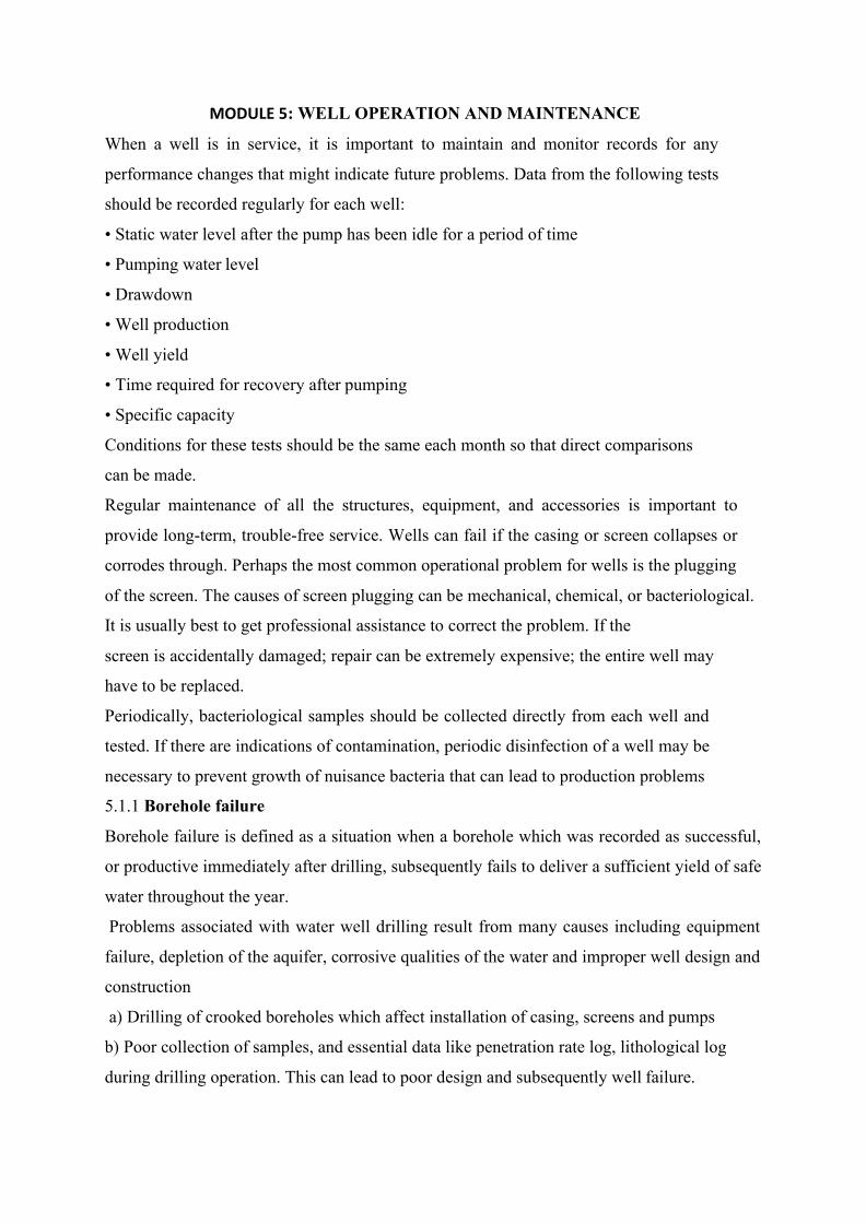
MODULE 5: WELL OPERATION AND MAINTENANCE
When a well is in service, it is important to maintain and monitor records for any
performance changes that might indicate future problems. Data from the following tests
should be recorded regularly for each well:
• Static water level after the pump has been idle for a period of time
• Pumping water level
• Drawdown
• Well production
• Well yield
• Time required for recovery after pumping
• Specific capacity
Conditions for these tests should be the same each month so that direct comparisons
can be made.
Regular maintenance of all the structures, equipment, and accessories is important to
provide long-term, trouble-free service. Wells can fail if the casing or screen collapses or
corrodes through. Perhaps the most common operational problem for wells is the plugging
of the screen. The causes of screen plugging can be mechanical, chemical, or bacteriological.
It is usually best to get professional assistance to correct the problem. If the
screen is accidentally damaged; repair can be extremely expensive; the entire well may
have to be replaced.
Periodically, bacteriological samples should be collected directly from each well and
tested. If there are indications of contamination, periodic disinfection of a well may be
necessary to prevent growth of nuisance bacteria that can lead to production problems
5.1.1 Borehole failure
Borehole failure is defined as a situation when a borehole which was recorded as successful,
or productive immediately after drilling, subsequently fails to deliver a sufficient yield of safe
water throughout the year.
Problems associated with water well drilling result from many causes including equipment
failure, depletion of the aquifer, corrosive qualities of the water and improper well design and
construction
a) Drilling of crooked boreholes which affect installation of casing, screens and pumps
b) Poor collection of samples, and essential data like penetration rate log, lithological log
during drilling operation. This can lead to poor design and subsequently well failure.

Tube well failures
Faulty Faulty Mechanical Corrosion Incrustation Interference Adverse design failure between wells aquifer
Over well
screen gravel pack
Lowering of water of water
Wrong Improper placement jointing
of well screen of pipe and well screen
Inadequate Shearing Lodging of development and foreign objects,
collapse including pump due to components
c) Use of drilling fluid in such proportion that will lead to sealing of the intake portion of the
well with mud cake or cause excessive mud invasion into the aquifer system
d) Use of substandard casings and screens in an attempt to save cost. This can result into
causing an incursion of soil or formational materials into the well
e) Use of inappropriate gravel packs materials like rock chippings
f) Lack of placement of sanitary seal or grout.
The design and construction details of the well should always be available with the well owner or the organization responsible for its maintenance. They will include the year of construction, method of drilling, well log, depth of bore, aquifer materials (grain-size distribution curve, if possible), location, diameter and type of strainer and casing pipe, gravel pack material (design curve showing the grading of gravel pack used), method of well development, pump specifications, initial discharge, drawdown and sand content.
Based on the data collected over the service period of the well, performance graphs are drawn showing the variation of well discharge against time (Fig. 8.1) and increase in sand pumping against time.
Fig. 5.1 Typical performance curves of sick wells for diagnosing the cause of failure

5.2.1 Indicators of water well problems There are four common symptoms associated with most water well problems:
Reduced well yield
Sediment in the water
Change in water quality
Dissolved gas in the water.
5.3.1 Causes of water well drilling problems Water well problems result from many causes including: -
I. Improper well design and construction,
II. Incomplete well development,
III. Borehole stability problems,
IV. Equipment failure,
V. Depletion of the aquifer,
VI. Corrosive qualities of the water (Incrustation build-up and Corrosion)
and
VII. Over pumping,
The first two causes relate to the expertise and performance of the drilling contractor.
Borehole stability problems, incrustation, corrosion and aquifer problems are related to
characteristics of the aquifer. Well users cause the last cause, over pumping.
Borehole maintenance should be taken more seriously and borehole owners should develop
the habit of carrying out regular maintenance on their borehole wells so as to ensure that they
reach their serviceability life. It is necessary that borehole drilling should be monitored by a
certified agency and that drilling license be issued to qualified water well drillers so as to
reduce the infiltration of inexperienced drillers into the water well drilling sector and to
reduce the drilling of sub-standard water wells. Owners of boreholes should consider
rehabilitating boreholes instead of abandoning them. Rehabilitation of wells can save money
and prevent the sub surface layers from losing stability as a result of excessive well drilling
5.3.2 Trouble-Shooting
A careful study of the performance graphs of a well can identify the cause for its failure. The inferences are drawn on the basis of the following considerations:
(i) Corrosion A sudden drop in the graph of well capacity versus time is an indication of failure of the tube well due to corrosion (Fig. 5.2).

(Fig. 5.2). Tube well due to corrosion
The other indication is increase in sand pumping,
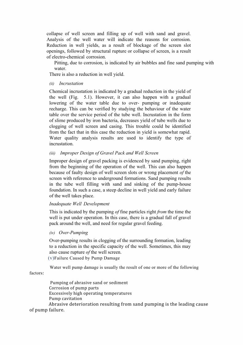
collapse of well screen and filling up of well with sand and gravel. Analysis of the well water will indicate the reasons for corrosion. Reduction in well yields, as a result of blockage of the screen slot openings, followed by structural rupture or collapse of screen, is a result of electro-chemical corrosion.
Pitting, due to corrosion, is indicated by air bubbles and fine sand pumping with water.
There is also a reduction in well yield.
(ii) Incrustation Chemical incrustation is indicated by a gradual reduction in the yield of the well (Fig. 5.1). However, it can also happen with a gradual lowering of the water table due to over- pumping or inadequate recharge. This can be verified by studying the behaviour of the water table over the service period of the tube well. Incrustation in the form of slime produced by iron bacteria, decreases yield of tube wells due to clogging of well screen and casing. This trouble could be identified from the fact that in this case the reduction in yield is somewhat rapid. Water quality analysis results are used to identify the type of incrustation.
(iii) Improper Design of Gravel Pack and Well Screen Improper design of gravel packing is evidenced by sand pumping, right from the beginning of the operation of the well. This can also happen because of faulty design of well screen slots or wrong placement of the screen with reference to underground formations. Sand pumping results in the tube well filling with sand and sinking of the pump-house foundation. In such a case, a steep decline in well yield and early failure of the well takes place. Inadequate Well Development This is indicated by the pumping of fine particles right from the time the well is put under operation. In this case, there is a gradual fall of gravel pack around the well, and need for regular gravel feeding.
(iv) Over-Pumping Over-pumping results in clogging of the surrounding formation, leading to a reduction in the specific capacity of the well. Sometimes, this may also cause rupture of the well screen.
(v)Failure Caused by Pump Damage
Water well pump damage is usually the result of one or more of the following factors:
Pumping of abrasive sand or sediment Corrosion of pump parts Excessively high operating temperatures Pump cavitation
Abrasive deterioration resulting from sand pumping is the leading cause of pump failure.

5.3.3 Water Well Maintenance Water wells require regular maintenance to ensure adequate water flow and continued drinking water safety. To ensure water quality, well water should be tested annually for total coliform bacteria and E. coli bacteria by a state accredited testing laboratory. Every three years, additional testing is recommended for pH and total dissolved solids as well as tests related to land uses occurring or expected to occur within sight of the well. Additionally, if there are obvious stains, tastes, or odors in water, seek testing that will help identify the source of these symptoms. Water wells should also be inspected annually for obvious signs of damage or contamination. Be sure the area within 30 metres around the well is clear of debris or items that might pollute the water supply. Get the well professionally inspected by a water well contractor every ten years. Keep all records related to the water well including: Water well completion report or log (if you have it) which should include information such as water well depth, date drilled, construction (including casing specifications, grouting and screen), and water well yield or flow rate in gallons per minute (gpm) Water quality test reports Past inspection reports Invoices from work done by water well contractors (including pump replacement) Water treatment equipment warranties, invoices and manuals To find some of this information you can check with the Pennsylvania Department of Conservation and Natural Resources (PA DCNR) Pennsylvania Groundwater Information System (PaGWIS) or contact a local well driller. 3.3.4 Well Performance As a water well ages, the rate at which water may be pumped (commonly referred to as the well yield, flow or performance) tends to decrease, especially in wells that were not properly developed when first drilled. A drop or complete loss of water production from a well can sometimes occur even in relatively new wells due to a lowered water level from persistent drought or over-pumping of the well which can dewater the water-bearing zones. More often, reduced well yield over time can be related to changes in the water well itself including: Incrustation from mineral deposits Bio-fouling by the growth of microorganisms Physical plugging of "aquifer" (the saturated layer of sand, gravel, or rock through which water is transmitted) by sediment
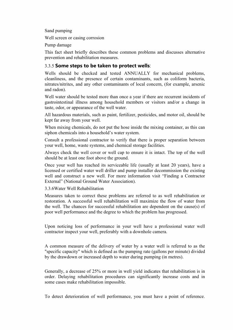
Sand pumping Well screen or casing corrosion Pump damage This fact sheet briefly describes these common problems and discusses alternative prevention and rehabilitation measures.
3.3.5 Some steps to be taken to protect wells: Wells should be checked and tested ANNUALLY for mechanical problems, cleanliness, and the presence of certain contaminants, such as coliform bacteria, nitrates/nitrites, and any other contaminants of local concern, (for example, arsenic and radon). Well water should be tested more than once a year if there are recurrent incidents of gastrointestinal illness among household members or visitors and/or a change in taste, odor, or appearance of the well water. All hazardous materials, such as paint, fertilizer, pesticides, and motor oil, should be kept far away from your well. When mixing chemicals, do not put the hose inside the mixing container, as this can siphon chemicals into a household’s water system. Consult a professional contractor to verify that there is proper separation between your well, home, waste systems, and chemical storage facilities. Always check the well cover or well cap to ensure it is intact. The top of the well should be at least one foot above the ground. Once your well has reached its serviceable life (usually at least 20 years), have a licensed or certified water well driller and pump installer decommission the existing well and construct a new well. For more information visit “Finding a Contractor External” (National Ground Water Association). 3.3.6Water Well Rehabilitation Measures taken to correct these problems are referred to as well rehabilitation or restoration. A successful well rehabilitation will maximize the flow of water from the well. The chances for successful rehabilitation are dependent on the cause(s) of poor well performance and the degree to which the problem has progressed. Upon noticing loss of performance in your well have a professional water well contractor inspect your well, preferably with a downhole camera. A common measure of the delivery of water by a water well is referred to as the "specific capacity" which is defined as the pumping rate (gallons per minute) divided by the drawdown or increased depth to water during pumping (in metres). Generally, a decrease of 25% or more in well yield indicates that rehabilitation is in order. Delaying rehabilitation procedures can significantly increase costs and in some cases make rehabilitation impossible. To detect deterioration of well performance, you must have a point of reference.

Often this reference is the original well construction and pump test data which are normally supplied to you by the well driller on a well completion report or well log when the well is installed. However, even if you do not have this information, significant changes in your well are also a warning sign. Major changes in any of the following well characteristics is an indication that your well or pump is in need of attention: Decreased pumping rate Decreased water level Decreased specific capacity Increased sand or sediment content in the water (cloudiness) Decreased total well depth The two most common methods to rehabilitate a water well are:
chemicals to dissolve the incrusting materials from the well physically cleaning the well Physical methods include using a brush attached to a drilling rig, high pressure jetting, hydrofracturing, and well surging.
Treatment of Pump Damage Usually, a pump will show some evidence that maintenance is in order. Most major causes of pump failure are related to mechanical problems such as bearings, stuffing boxes, impellers, and pump bowl assemblies. Maintenance, repair and replacement of the pump and motor parts should be in accordance with the manufacturer's recommendations. Correction of recurring sand pumping problems is in some cases cost prohibitive. Total well replacement may in the long run be more economical than rehabilitation of a severely deteriorated well. This is especially true of shallow wells. However, when drilling a new well is not feasible, it is sometimes possible to extract and replace a severely damaged well screen in the existing well. Installation of a smaller diameter screen (also known as a liner) inside the original well screen has also been used as a remedy. Various devices can also be installed to even out or reduce the flow of water entering the well and thus reduce the potential for sand pumping. REFERENCES
Michael, A. M., Khepar, S. D., Sondhi, S. K.(2008)Water Wells and Pumps, Tata
McGraw-Hill Publishing Company Limited NEW DELHI, 2nd Edition,Pp
312-
Ahmed N, Taylor, S W. Sheng , Z (2014 ) Hydraulics of Wells Design,

Construction,
Testing, and Maintenance of Water Well Systems Prepared by the Task
Committee on Hydraulics of Wells of the Groundwater Hydrology Technical
Committee of the Groundwater Council and Watershed Council of the
Environmental and Water Resources Institute of the American Society of Civil
Engineers
Oyebode, J. O., Oyegoke .S.O., Olowe K.O. Onoh P. Adebayo V.B. (2015 )
Borehole Drilling, Usage, Maintenance and Sustainability in Ado- Ekiti,
Nigeria , American Journal of Engineering Research (AJER) e-ISSN: 2320-
0847 p-ISSN : 2320-0936 Volume-4, Issue-9, pp-01-12
Swistock, B, Rizzo, D (2014) Water Well Maintenance and Rehabilitation