Embed Size (px)
Citation preview

Training aid7SR224 three-phase control relay
Type SDR 15.5 kV to 38 kV three-phase distribution recloser
Answers for infrastructure.
www.usa.siemens.com/reclosers
SDR recloser
A PH Fault
B PH Fault
C PH Fault
Ground Fault
SGF
Lockout
Aux Power OK
Recloser OK
Open
Close
Reclose ON
Hot Line Tag ON
Ground Fault Protn OFF
SGF Protn OFF
All Protn OFF
Inst Protn OFF
Trip & Reclose

2
Table of contents
Type 7SR224 protection and control relay front panel 03
Type 7SR224 protection and control relay operation exercises 04 – 06
Type 7SR224 protection and control relay navigation tree 06 – 07
Control mode tree 08 – 11
Settings mode tree 12 – 18
Settings change examples 19 – 25
Instrument mode tree 26 – 28
Viewing meter examples 29 – 31
Fault data mode tree 32
Viewing fault data example 33
Troubleshooting and notes 34 – 35

3
SDR recloser
A PH Fault
B PH Fault
C PH Fault
Ground Fault
SGF
Lockout
Aux Power OK
Recloser OK
Open
Close
Reclose ON
Hot Line Tag ON
Ground Fault Protn OFF
SGF Protn OFF
All Protn OFF
Inst Protn OFF
Trip & Reclose
1. MLFB number (model)
2. Ratings label
3. In = CT secondary current (In = 1A for type SDR recloser) frequency = 50/60 Hz (60 Hz for type SDR recloser)
4. Vn = voltage supplied to relay from voltage sensors (63.5 for type SDR recloser)
5. Vx = power supply voltage range (48 Vdc for type SDR recloser) and BI = voltage to activate a binary input (19 Vdc for type SDR recloser)
6. Programming port
1
2
7
8
9
10
6
11
12
13
14
2
3
4
5
Item Button and/or LED If associated LED is lit
F1/L9 Push-to-open recloser Recloser is OPEN
F2/L10 Push-to-close recloser Recloser is CLOSED
F3/L11Push-to-toggle reclose functionality
On/OffReclose functionality is
ON
F4/L12 Push-to-toggle hot line tag On/Off Hot line tag is ON
F5/L13Push-to-toggle ground fault
protection On/OffGround fault
protection is OFF
F6/L14Push-to-toggle sensitive earth fault
protection On/OffSEF protection is OFF
F7/L15 Push-to-toggle all protection On/Off All protection is OFF
F8/L16Push-to-toggle instantaneous
protection On/OffInstantaneous
protection is OFF
F9/L17 User defined User defined
F10/L18 User defined User defined
F11/L19 User defined User defined
F12/L20 Push-to-trip and reclose recloser ----
Item Button and/or LED If associated LED is lit
7 A PH fault Phase A target
8 B PH fault Phase B target
9 C PH fault Phase C target
10 Ground fault Ground fault target
11 SEF Sensitive earth fault (SEF) target
12 Lockout Recloser is locked out
13 Aux power OK AC input power to control cubicle OK
14 Recloser OKCapacitors charged and system ready
to close or open
Note: If buttons are labeled differently than shown above, factory settings have been reprogrammed.
F1/L9
F2/L10
F3/L11
F4/L12
F5/L13
F6/L14
F7/L15
F8/L16
F9/L17
F10/L19
F11/L20
F12/L21

4
Type 7SR224 protection and control relay operation exercises
Example 1: open recloser
Press LCD screen Press Recloser will open
Green LED at F1 will illuminate.
Open Open SDR pressed
ENTER to confirm
Example 2: close recloser
Press LCD screen Press Recloser will close
Red LED at F2 will illuminate.
Close Close SDR pressed
ENTER to confirm
Example 3: toggle reclosing operation on and off
Press LCD screen Press Recloser will not open or close
Green LED at F3 will toggle on and off.
LED:
On = reclosing enabled
Off = reclosing disabled.
Reclose ON
Reclose On/Off pressed
ENTER to confirm

5
Example 4: toggle hot line tag on and off
Press LCD screen Press Recloser will not open or close
Red LED at F4 will toggle on and off.
LED:
On = hot line tag enabled
Off = hot line tag disabled.
Hot Line Tag ON
Hot Line Tag On/Off pressed
ENTER to confirm
Example 5: toggle ground fault protection on and off
Press LCD screen Press Recloser will not open or close
Red LED at F5 will toggle on and off.
LED:
On = ground fault protection disabled
Off = ground fault protection enabled.
Ground Fault Protn OFF
GF Protn ON/OFF pressed
ENTER to confirm
Example 6: toggle SEF protection on and off
Press LCD screen Press Recloser will not open or close
Red LED at F6 will toggle on and off.
LED:
On = SEF protection disabled
Off = SEF protection enabled.
SGF Protn OFF
SGF Protn ON/OFF pressed
ENTER to confirm
Example 7: toggle all protection on and off
Press LCD screen Press Recloser will not open or close
Red LED at F7 will toggle on and off.
LED:
On = all protection disabled
Off = all protection enabled.
All Protn OFF
All Protn On/Off pressed
ENTER to confirm

6
Type 7SR224 protection and control relay navigation tree
For all arrows pointing , press
For all arrows pointing , press
To go back one level, press
For detailed settings mode tree, please refer to page 12.
The following pages will present the navigation tree of the relay settings tree using the navigation buttons.
Example 8: toggle instantaneous (fast) protection on and off
Press LCD screen Press Recloser will not open or close
Red LED at F8 will toggle on and off.
LED:
On = INST (fast) protection disabled
Off = INST (fast) protection enabled.
Inst Protn OFF
INST Protn ON/OFF pressed
ENTER to confirm
To scroll up , press
To select, press

7
Type 7SR224 protection and control relay navigation tree
Press
Recloser Name
ENTER to control
CONTROL MODE SETTINGS MODE INSTRUMENT MODE FAULT DATA
CB: OPEN/CLOSED/TRAVELING SYSTEM CONFIG FAVORITE METERS FAULT 1
AR: Out of Service CT/VT CONFIG CURRENT METERS FAULT 2
AR: Trip & Reclose FUNCTION CONFIG VOLTAGE METERS FAULT 3
AR: Trip & Lockout CURRENT PROT'N FREQUENCY METERS FAULT 4
Hotline Working IN/OUT VOLTAGE PROT'N POWER METERS FAULT 5
G/F Protection IN/OUT SUPERVISION ENERGY METERS FAULT 6
SGF Protection IN/OUT CONTROL & LOGIC DIRECTIONAL METERS FAULT 7
Inst Protection IN/OUT INPUT CONFIG THERMAL METERS FAULT 8
Loss of Volts IN/OUT1 OUTPUT CONFIG AUTORECLOSE METERS FAULT 9
Battery Test MAINTENANCE LOSS OF VOLTS METERS FAULT 10
Set Local DATA STORAGE MAINTENANCE METERS
Set L or R COMMUNICATIONS GENERAL ALARM METERS
Set Remote BATTERY CONDITION
Set Service CAPACITOR CONDITION
POWER QUALITY METERS
DEMAND METERS
BINARY INPUT METERS
BINARY OUTPUT METERS
VIRTUAL METERS
COMMUNICATION METERS
MISCELLANEOUS METERS
QUICK LOGIC METERS
Footnote:1 This function only available with LOV relay
option.

8
Control mode tree
Press
Recloser Name
enter to control
If the LCD screen does not read ENTER to CONTROL, press until it does. This will not cause the recloser to operate.
This is the first of four modes in the relay tree, which bring you to multiple screens that will allow you to control the recloser.
Press
CB: OPEN To open/close the recloser, the LCD screen will read "CB: OPEN," "CB: CLOSED" or "CB: TRAVELING" indicating the recloser position. Traveling indicates lack of proper position indication. Refer to Troubleshooting table on page 34.
Press CB: OPEN Close|Open to select
Press
Select "Open" or "Close"
CB: OPEN Confirm Open
ENTER to confirm
Press
Recloser will open/close.
Press
AR: Out of Service To toggle auto-reclose on/off, the LCD screen will read "AR: In Service," or "AR: Out of Service" indicating auto-reclose functionality being in or out of service.
Press AR: In Service In|Out
to select
Press
Select "In" or "Out"
AR: In Service Confirm Out
ENTER to confirm
Press
Auto-reclose functionality will toggle between in and out of service.
Control mode tree continues on page 9.
Press
CONTROL MODE

9
AR: Trip & Reclose To trip and close the recloser. This screen will allow the user to trip the recloser, then the recloser will automatically reclose.
Press AR: Trip & Reclose Confirm Action
ENTER to confirm
Press
Press
G|F Protection: IN To toggle ground fault prot'n On/Off, the LCD screen will read "G/F Protection: IN," or "GF: Protection: OUT" indicating ground fault protection is in/out of service.
Press G/F Protection: IN In|Out
to select
Press
Press
SGF Protection: In To toggle sensitive ground fault protection On/Off, the LCD screen will read "SGF Protection: IN," or "SGF Protection: OUT," indicating sensitive ground fault protection is in/out of service.
Press SGF Protection: IN In|Out
to select
Press
Select "In" or "Out"
SGF Protection: IN Confirm Out
ENTER to confirm
Press
Sensitive ground fault protection will toggle between in and out of service.
Control mode tree continues on page 10.
Press
Recloser will trip, then reclose.
AR: Trip & Lockout Confirm Action
ENTER to confirm
Press
Recloser will trip and lockout.
AR: Trip & Lockout To trip and lockout the recloser. This screen will allow the user to trip and lockout the recloser.
Press
Press
Hotline Working: IN In|Out
to select
PressHotline Working: IN To toggle hot line tag On/Off. This screen will read "Hotline Working: IN" or "Hotline Working: OUT" indicating hot line tag being in/out of service.
Press
Press
Select "In" or "Out"
G/F Protection: IN Confirm OUT
ENTER to confirm
Press
Ground fault protection will toggle between in and out of service.
Select "In" or "Out"
Hotline Working Confirm Out
ENTER to confirm
Press
Hot line tag functionality will toggle between in and out of service.

10
Inst Protection: IN To toggle Inst (fast) Protection On/Off, the LCD screen will read "Inst Protection: IN," or "Inst Protection: OUT" indicating Inst (fast) protection is in or out of service.
Press Inst Protection: IN In|Out
to select
Press
Select "In" or "Out"
Inst Protection: IN Confirm Out
ENTER to confirm
Press
Inst (fast) Protection will toggle between in and out of service.
Press
Loss of Volts: IN To toggle between Loss of Volts On/Off, the LCD screen will read "Loss of Volts: In," or "Loss of Volts: Out" indicating loss of voltage detection is in or out of service.
Note: This function is only available with LOV relay option.
Press Loss of Volts: IN IN|OUT
to select
Press
Select "In" or "Out"
Loss of Volts: IN Confirm Out
ENTER to confirm
Press
Loss of volts will toggle between in and out of service.
Battery Test To manually initiate a battery test. This LCD screen will allow the user to manually initiate a battery test.
Press Battery Test Confirm Start
ENTER to confirm
Press
Battery Test Active
ENTER to control
Control will proceed through a battery test. (A capacitor test will immediately follow upon completion of the battery test.)
Press
Control mode tree continues on page 11.
Press
Set Local To set operational mode to local, the LCD screen will read "Set Local: mode" (where mode is local, L or R, remote or out of service.)
Press Set Local: mode Confirm Local Mode
ENTER to confirm
Press
Press
Relay will be in local mode.
Set L or R: mode Confirm L or R Mode
ENTER to confirm
Press
Relay will be in L or R mode.
Set L or R To set operational mode to L or R, the LCD screen will read "Set L or R: mode" (where mode is local, L or R, remote or out of service.)
Press
Press

11
Set Remote To set operational mode to Remote, the LCD screen will read "Set Remote: mode" (where mode is local, L or R, remote or out of service.)
Press Set Remote: mode Confirm Remote Mode
ENTER to confirm
Press
Press
Recloser will be in remote mode.
Set Service: mode Confirm Service Mode
ENTER to confirm
Press
Relay will be in out-of-service mode.
Set Service To set operational mode to Out of Service, the LCD screen will read "Set Service: mode" (where mode is local, L or R, remote or out of service.)
Press
Press
Note: The Out of Service mode will inhibit all local and remote control of relay. To regain local control, refer to Changing the Operating Mode from the settings tree on page 23.

12
Press
FUNCTION CONFIG This menu allows the user to enable or disable functions and features available in the relay.
Press
CURRENT PROT'N This menu allows the user to change current protection settings. For examples of how to changes these settings, please refer to page 22.
Press
This menu allows the user to change voltage protection settings.
Press
Settings mode tree
Press
Recloser Name
enter to control
CONTROL MODE This is the second of four modes in the relay tree, which bring you to multiple screens that will allow you to control the recloser.
Press SETTINGS MODE
Press
SYSTEM CONFIG This menu contains system settings, including language, frequency, date, passwords, etc.
Press
CT/VT CONFIG This menu allows the user to change current transformers and voltage transformers settings.
VOLTAGE PROT'N
Settings mode tree continues on page 13.
13
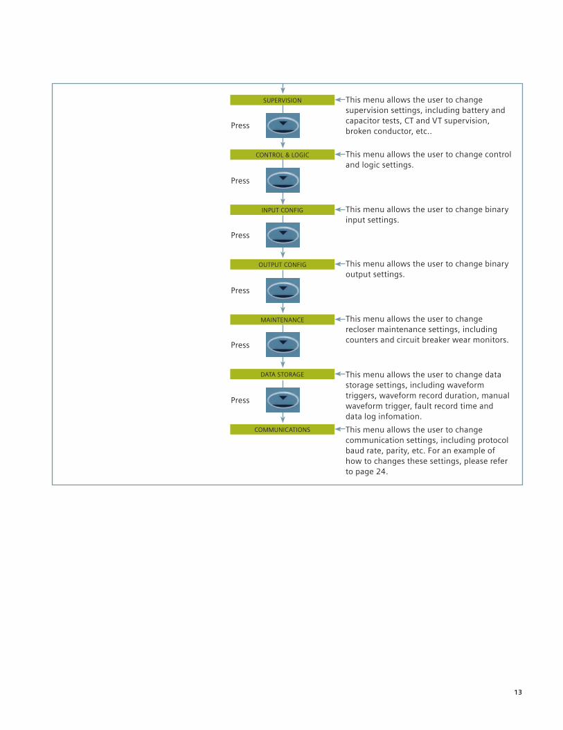
SUPERVISION This menu allows the user to change supervision settings, including battery and capacitor tests, CT and VT supervision, broken conductor, etc..
Press
This menu allows the user to change control and logic settings.
Press
INPUT CONFIG This menu allows the user to change binary input settings.
Press
OUTPUT CONFIG This menu allows the user to change binary output settings.
Press
MAINTENANCE This menu allows the user to change recloser maintenance settings, including counters and circuit breaker wear monitors.
Press
DATA STORAGE This menu allows the user to change data storage settings, including waveform triggers, waveform record duration, manual waveform trigger, fault record time and data log infomation.
Press
COMMUNICATIONS This menu allows the user to change communication settings, including protocol baud rate, parity, etc. For an example of how to changes these settings, please refer to page 24.
CONTROL & LOGIC

14
SETTINGS MODE
SYSTEM CONFIG Language Setting Phase VT Ratio Prim
Active Group Phase VT Ratio Sec
System Frequency Vx Nom Voltage
View/Edit Group Vx Voltage Trim Magnitude
Setting Dependencies Vx Voltage Trim Angle
Favorite Meters Timer Vx VT Ratio Prim
Backlight Timer Vx VT Ratio Sec
Date Phase Current Input
Time Phase CT Ratio
Curr Set Display Ground Current Input
G/F Curr Set Display
Export Power/Lag Var
CT/VT CONFIG
Settings mode detailed tree structure
Ground CT Ratio
I1, I2, I3 Connections
V1, V2, V3 Connections
Phase Rotation
Phase Overcurrent
Voltage Cont O/C
Cold Load
Measured G/F
Sensitive G/F
Restricted G/F
Function Config
Select Grp Mode
Clock Sync from BI
Operating Mode
Setting Password
Control Password
Trip Alert
General Alarm Alert
Relay Identifier
Circuit Identifier
Phase Nom Voltage
NPS Overcurrent
Under Current
Thermal
Phase U/O Voltage
Phase Voltage Trim Magnitude
Phase Voltage Trim Angle
Phase Voltage Config Vx U/O Voltage
Settings mode detailed tree continues on page 15.

15
CURRENT PROT'N
NPS Overvoltage
Neutral Overvoltage
U/O Frequency
CB Fail
VT Supervision
CT Supervision
Broken Conductor
Trip Cct Supervision
Inrush Detector
CB Counters
I^2t CB Wear
Battery Test
67
Capacitor Test
LOV Automation1
27Sag & 59Swell
PHASE OVERCURRENT
VOLTAGE CONT O/C
COLD LOAD
MEASURED G/F
SENSITIVE G/F
Settings mode detailed tree continues on page 16.
51-1 thru 51-4
50-1 thru 50-4
51V
51 C-1
67-G
51G-1 thru 51G-4
50G-1 thru 50G-4
67SGF
51SGF-1 thru 51SGF-4
RESTRICTED G/F 64-H
Footnote:1 This function only available
with LOV relay option.
16
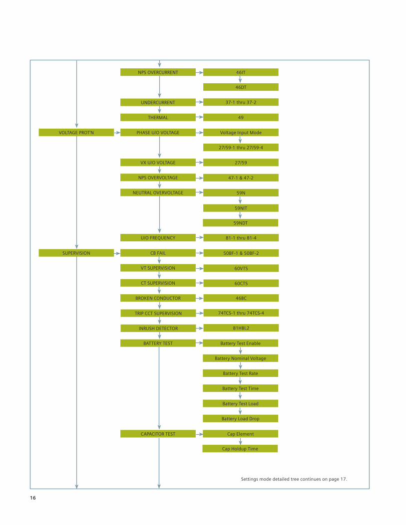
VOLTAGE PROT'N
NPS OVERCURRENT
UNDERCURRENT
THERMAL
PHASE U/O VOLTAGE
VX U/O VOLTAGE
NPS OVERVOLTAGE
NEUTRAL OVERVOLTAGE
U/O FREQUENCY
46BC
CB FAIL
VT SUPERVISION
CT SUPERVISION
BROKEN CONDUCTOR
BATTERY TEST
CAPACITOR TEST
Settings mode detailed tree continues on page 17.
74TCS-1 thru 74TCS-4
81HBL2
Battery Test Enable
Battery Nominal Voltage
Battery Test Rate
Battery Test Time
Battery Test Load
Battery Load Drop
Cap Element
Cap Holdup Time
46IT
46DT
37-1 thru 37-2
49
Voltage Input Mode
27/59-1 thru 27/59-4
27/59
47-1 & 47-2
59N
59NIT
59NDT
81-1 thru 81-4
SUPERVISION 50BF-1 & 50BF-2
60VTS
60CTS
TRIP CCT SUPERVISION
INRUSH DETECTOR

17
CONTROL & LOGIC
POWER QUALITY
AUTORECLOSE PROT'N
AUTORECLOSE CONFIG
GENERAL ALARMS
QUICK LOGIC
INPUT MATRIX
FUNCTION KEY CONFIG
Settings mode detailed tree continues on page 18.
BINARY OUTPUT CONFIG
LED CONFIG
PICKUP CONFIG
CB COUNTERS CB Counters Enable
I^2T Counter Enable
Voltage Input Mode
27SAG
59Swell
79
79
Line Check Trip
Close CB Delay
Close CB Pulse
Reclaim Timer
Blocked Close Delay
Open CB Delay
Open CB Pulse
INPUT CONFIG
CB Controls Latched
Quick Logic Enable
E1 thru E16
FUNCTION KEY MATRIX
BINARY INPUT CONFIG
MANUAL CLOSE
CIRCUIT BREAKER
OUTPUT CONFIG
MAINTENANCE
I^2T CB WEAR
OUTPUT MATRIX

18
DEMAND/DATA LOG
EVENT STORAGE
ENERGY STORAGE
COM2-USB Protocol
COM1-RS485 Mode
COM2-USB Mode
DNP3 Unsolicited Events
DNP3 Destination Address
COMMUNICATIONS
COM1-RS485 Baud Rate
COM1-RS485 Parity
Station Address
COM1-RS485 Protocol
WAVEFORM STORAGE
FAULT STORAGE
DATA STORAGE
DNP3 Application Timeout
19
Settings change examples
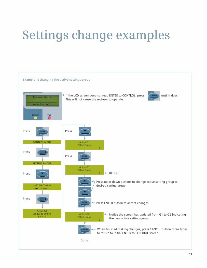
Press
Recloser Name
enter to control
If the LCD screen does not read ENTER to CONTROL, press until it does. This will not cause the recloser to operate.
CONTROL MODE
Press
SETTINGS MODE
SYSTEM CONFIG to view
Active G1 Language Setting
English
Press
Active G1 Active Group
1
Blinking
Done
Example 1: changing the active settings group
Press
Press
Press
Active G1 Active Group
1
Press up or down buttons to change active setting group to desired setting group.
Notice the screen has updated from G1 to G2 indicating the new active setting group.
Active G2 Active Group
2
When finished making changes, press CANCEL button three times to return to initial ENTER to CONTROL screen.
Press ENTER button to accept changes.

20
Press
Recloser Name
enter to control
If the LCD screen does not read ENTER to CONTROL, press until it does. This will not cause the recloser to operate.
CONTROL MODE
Press
SETTINGS MODE
SYSTEM CONFIG to view
Active G1 Language Setting
English
Press
Active G1 View/Edit Group
1
Blinking
Done
Example 2: changing the settings group that you are viewing/editing
Press
Press until the following appears
Press
Active G1 View/Edit Group
1
Notice the screen has updated from G1 to G2 indicating the new active setting group.
Active G1 View/Edit Group
2
Press up or down buttons to change active setting group to desired setting group.
When finished making changes, press CANCEL button three times to return to initial ENTER to CONTROL screen.
Press ENTER button to accept changes.

21
Press
Recloser Name
enter to control
If the LCD screen does not read ENTER to CONTROL, press until it does. This will not cause the recloser to operate.
CONTROL MODE
Press
SETTINGS MODE
SYSTEM CONFIG To view
Active G1 Language Setting
English
Press
Active G1 Settings Password
Not Active
Blinking
Done
Example 3: changing a password
Press
Press until the following appears
Press
Active G1 New Password
_
Press up or down buttons to enter a four-digit alphanumeric password.
Active G1 Confirm Password
_
Press once more to change the control password.
Press TEST/RESET button to move on digit to the right.
Press ENTER button to accept changes.
Repeat previous step.
Active G1 Setting Password
Code = 1682678776
The relay will present a code. Retain this code in case of a lost password. Refer to the instruction manual for the Siemens type 7SR224 recloser control relay (standard control and protection relay option) http://www.usa.siemens.com/reclosers
When finished making changes, press CANCEL button three times to return to initial ENTER to CONTROL screen.
You will now be prompted to enter the password once
before you can make a setting change. Follow the
same process to change the password at the control
level.
Note: To deactivate the password feature, change the password to "NONE."

22
Press
Recloser Name
enter to control
If the LCD screen does not read ENTER to CONTROL, press until it does. This will not cause the recloser to operate.
CONTROL MODE
Press
SETTINGS MODE
CURRENT PROTN to view
CURRENT PROTN PHASE OVERCURRENT
to view
Press until the following appears
Active G1 View G1 67 Char Angle
45 deg
Blinking
Done
Example 4: changing the pickup level of phase overcurrent element 51-1
Press
Press
Press until the following appears
Active G1 View G1 51-1 Setting
_x In
Press up or down buttons to change desired pickup level to desired current level.
Active G1 View G1 51-1 Setting
_x In
Press ENTER button to accept changes.
When finished making changes, press CANCEL button four times to return to initial ENTER to CONTROL screen.
Note: "Active G1 View G1" means that the active group settings group is group 1. If this is not the group you wish to edit, follow the instructions in Example 2 on page 19 to change the settings group.
Press
Active G1 View G1 51-1 Setting
_x In
Note: "_xIn" refers to the value times the nominal current that equals the trip setting. In = 800 A for type SDR reclosers.

23
Press
Recloser Name
enter to control
If the LCD screen does not read ENTER to CONTROL, press until it does. This will not cause the recloser to operate.
CONTROL MODE
Press
SETTINGS MODE
SYSTEM CONFIG to view
Active G1 Language Setting
English
Press
Active G1 Operating Mode Out Of Service
Blinking
Done
Example 5: changing the operating mode from the settings tree
Press
Press until the following appears
Press
Active G1 Operating Mode Out Of Service
Notice the screen has updated from Out Of Service to Local or Remote, Remote or Local mode.
Active G1 Operating Mode Local or Remote
Press up or down buttons to change operating mode to desired mode.
When finished making changes, press CANCEL button three times to return to initial ENTER to CONTROL screen.
Press ENTER button to accept changes.

24
Active G1 Station Address
0
Press
Recloser Name
enter to control
If the LCD screen does not read ENTER to CONTROL, press until it does. This will not cause the recloser to operate.
CONTROL MODE
Press
SETTINGS MODE
COMMUNICATIONS to view
Press until the following appears
Active G1 COM1-RS485 Baud Rate
19200
Blinking
Done
Example 6: changing the baud rate on COM1
Press
Press until the following appears
Active G1 COM1-RS485 Baud Rate
19200
Press up or down buttons to change baud rate as desired.
Active G1 View G1 51-1 Setting
800.00A
Press ENTER button to accept changes.
When finished making changes, press CANCEL button four times to return to initial ENTER to CONTROL screen.

25
Press
Recloser Name
enter to control
If the LCD screen does not read ENTER to CONTROL, press until it does. This will not cause the recloser to operate.
CONTROL MODE
Press until the following appears
Battery Test
Battery Test Confirm Start
Battery Test Active
Press
Done
Example 7: manually initiating the battery test
Press
Note: Result will be displayed at end of test.

26
Press
Recloser Name
enter to control
CONTROL MODE
This menu will allow the user to view the favorite meters.
Press SETTINGS MODE
Press
VOLTAGE METERS
Press
FREQUENCY METERS
Instrument mode tree continues on page 27.
Instrument mode tree
Press
Press
FAVORITE METERS
Press
CURRENT METERS
Press
Press
POWER METERS
Press
ENERGY METERS
This menu will allow the user to view the current meters.
This menu will allow the user to view the voltage meters.
This menu will allow the user to view the frequency meters.
This menu will allow the user to view the power meters.
This menu will allow the user to view the energy meters - active energy, reactive energy.
INSTRUMENT MODE

27
This menu will allow the user to view the thermal meters.
Press
LOSS OF VOLTS METERS
Press
MAINTENANCE METERS
Instrument mode tree continues on page 28.
Press
THERMAL METERS
Press
AUTORECLOSE METERS
Press
Press
GENERAL ALARM METERS
Press
BATTERY CONDITION
This menu will allow the user to view the auto-reclose meters.
This menu will allow the user to view the loss-of-volts meters if loss-of-volts function is used. This is only available with the LOV relay option.
This menu will allow the user to view the maintenance meters - counters.
This menu will allow the user to view the general alarm meters, which indicates which alarms are present.
This menu will allow the user to view the battery condition meters.
DIRECTIONAL METERSThis menu will allow the user to view the directional meters if directional current elements are used.
CAPACITOR CONDITION
Press
POWER QUALITY METERS
Press
DEMAND METERS
Press
This menu will allow the user to view the capacitor condition meters.
This menu will allow the user to view the power quality meters: SIARFI, SMARFI, Interrupts, etc.
This menu will allow the user to view the demand meters.

28
This menu will allow the user to view the binary output meters - _ indicates status is low, 1 indicates status is high.
Press
COMMUNICATION METERS
Press
MISCELLANEOUS METERS
Press
BINARY OUTPUT METERS
Press
VIRTUAL METERS
Press
QUICK LOGIC METERS
This menu will allow the user to view the virtual meters - _ indicates status is low, 1 indicates status is high.
This menu will allow the user to view the communications meters.
This menu will allow the user to view the miscellaneous meters: date, time, waveform records, fault records, event records and data log records.
This menu will allow the user to view the quick logic meters - _ indicates status is low, 1 indicates status is high.
BINARY INPUT METERSThis menu will allow the user to view the binary input meters - _ indicates status is low, 1 indicates status is high.

29
Viewing meter examples
Press
Recloser Name
enter to control
If the LCD screen does not read ENTER to CONTROL, press until it does. This will not cause the recloser to operate.
CONTROL MODE
Press until the following appears
INSTRUMENTS MODE
Current Meters to view
Primary Current 1a 0.00kA 1b 0.00kA 1c 0.00kA
Press until the following appears
Done
Example 1: viewing the current meters and adding them to favorite meters
Press
Press
Press
Blinking
Confirm Add to Favorites
YES
Displays primary current levels.
Press the down button to view other current meters:
Secondary current
Nominal current (for reclosers, In = 1A)
Primary ground current
Secondary ground current
Nomimal ground current (for reclosers, In = 1A)
I-sequence components
Second harmonic current
Last trip phase fault
Last trip earth fault.
Press ENTER to make the meter a favorite meter.
Any meter or meters in the instrument mode may be added to favorite meters. The favorite meters may be displayed on the LCD screen, in rotating order, after no buttons have been pressed for a selectable period of time. To turn on and set the timer, select Setting Mode System Config Favorite Meters Timer.

30
Recloser Name
enter to control
If the LCD screen does not read ENTER to CONTROL, press until it does. This will not cause the recloser to operate.
Example 2: viewing the voltage meters and adding them to favorite meters
Press
CONTROL MODE
Press until the following appears
INSTRUMENTS MODE
Voltage Meters to view
Primary Ph-Ph Voltage Vab 0.00kV Vbc 0.00kV Vca 0.00kV
Press until the following appears
Done
Press
Press
Press
Blinking
Confirm Add to Favorites
YES
Displays primary phase-to-phase voltage levels
Press the down button to view other voltage meters:
Secondary phase-phase voltage
Nominal phase-phase voltage (for reclosers, Vn = 63.5 V)
Primary phase-neutral voltage
Secondary phase-neutral voltage
Nomimal phase-neutral voltage (for reclosers, Vn = 63.5 V)
V-sequence components
Calculated ground voltage
CS/NVD voltage (VX)
Last trip voltage.
Press ENTER to make the meter a favorite meter.
Any meter or meters in the instrument mode may be added to favorite meters. The favorite meters may be displayed on the LCD screen, in rotating order, after no buttons have been pressed for a selectable period of time. To turn on and set the timer, select Setting Mode System Config Favorite Meters Timer.
31
Recloser Name
enter to control
If the LCD screen does not read ENTER to CONTROL, press until it does. This will not cause the recloser to operate.
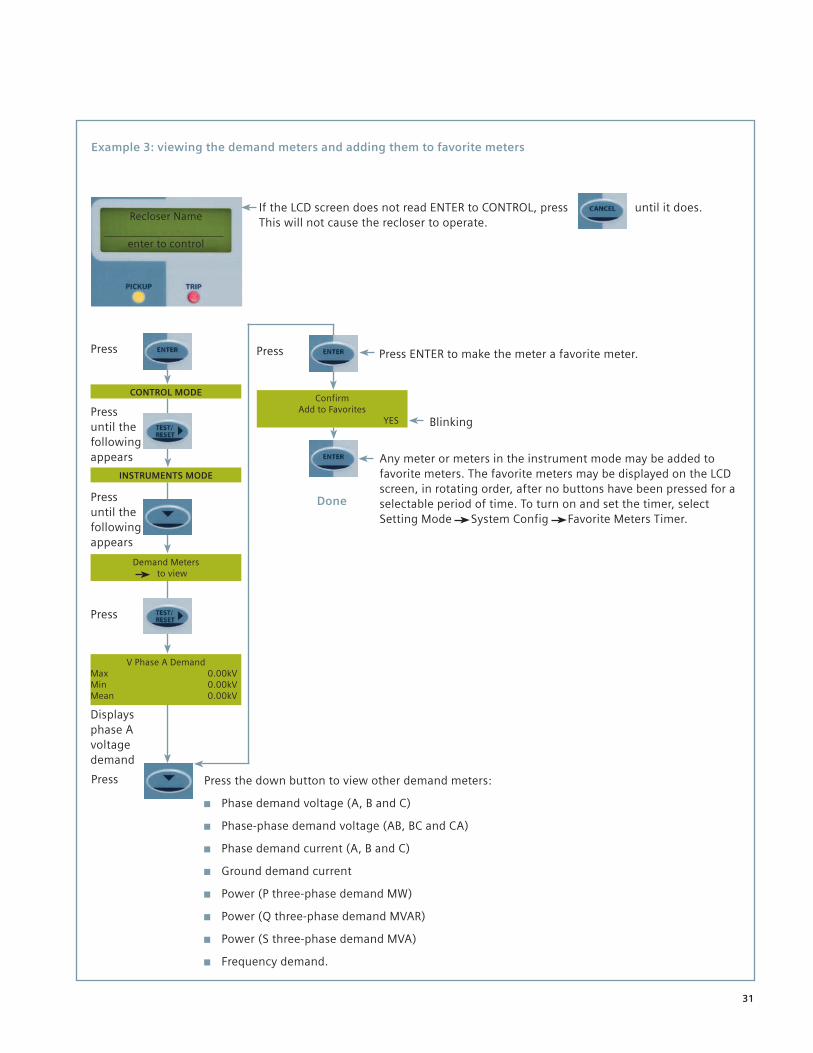
Example 3: viewing the demand meters and adding them to favorite meters
Press
CONTROL MODE
Press until the following appears
INSTRUMENTS MODE
Demand Meters to view
V Phase A Demand Max 0.00kV Min 0.00kV Mean 0.00kV
Press until the following appears
Done
Press
Press
Press
Blinking
Confirm Add to Favorites
YES
Displays phase A voltage demand
Press the down button to view other demand meters:
Phase demand voltage (A, B and C)
Phase-phase demand voltage (AB, BC and CA)
Phase demand current (A, B and C)
Ground demand current
Power (P three-phase demand MW)
Power (Q three-phase demand MVAR)
Power (S three-phase demand MVA)
Frequency demand.
Press ENTER to make the meter a favorite meter.
Any meter or meters in the instrument mode may be added to favorite meters. The favorite meters may be displayed on the LCD screen, in rotating order, after no buttons have been pressed for a selectable period of time. To turn on and set the timer, select Setting Mode System Config Favorite Meters Timer.
32
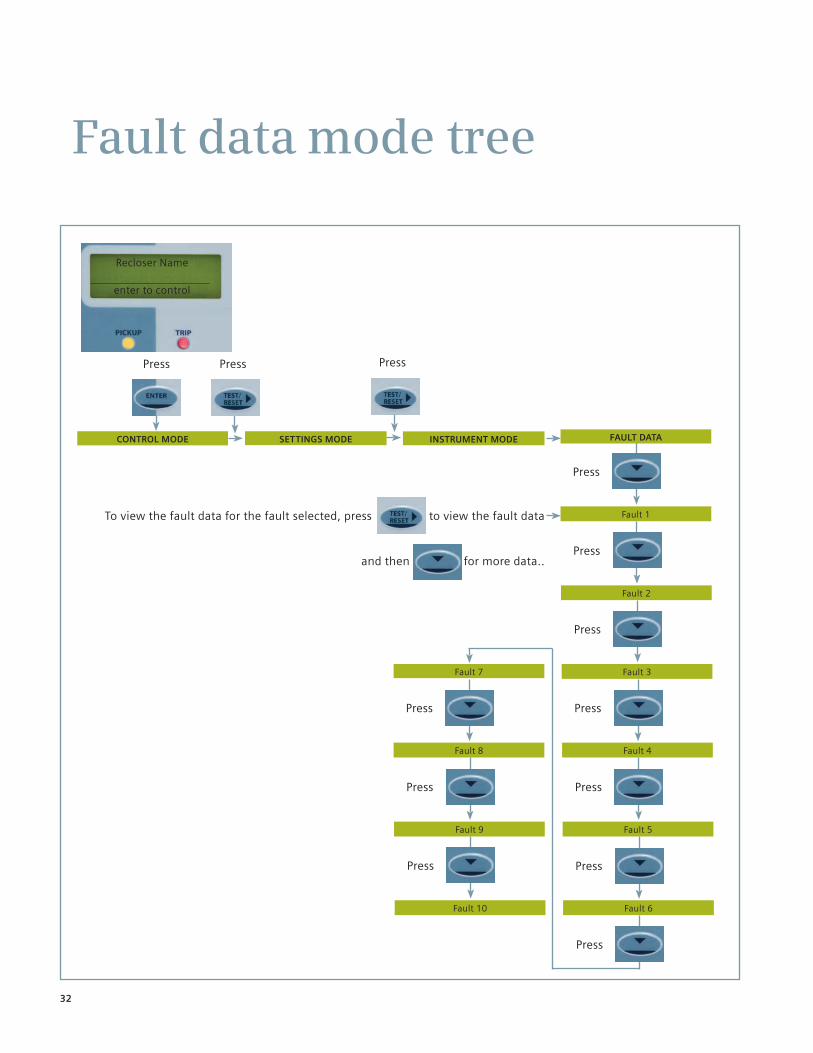
Fault 7
Press
Recloser Name
enter to control
CONTROL MODE
To view the fault data for the fault selected, press to view the fault data
and then for more data..
SETTINGS MODE
Press
Fault 3
Press
Fault 4
Fault data mode tree
Press
Fault 1
Press
Fault 2
Press
Press
Fault 5
Press
Fault 6
FAULT DATAINSTRUMENT MODE
Press Press
Press
Fault 10
Press
Fault 8
Press
Fault 9

33
Viewing fault data example
Press
Recloser Name
enter to control
If the LCD screen does not read ENTER to CONTROL, press until it does. This will not cause the recloser to operate.
CONTROL MODE
Press until the following appears
FAULT DATA MODE
Fault 1 03/04/09 to view
Fault 1 Page 1/6 03/04/09 14:57:28:00.300
Example 1: fault data record 1
Press
Press
Press
Done
Displays date and time of Fault 1.
Displays elements that picked up during Fault 1.
Fault 1 Page 2/6 G1 51G 46BC 50BF-1 50-1 51-2
Press
Displays Ia and Ib levels during Fault 1.
Fault 1 Page 3/6 Ia=0.304kA Ib=0.000kA
Press
Displays Ic
and In levels during Fault 1.
Fault 1 Page 4/6 Ic=0.304kA In=0.060kA
Displays Ig
and Va levels during Fault 1.
Fault 1 Page 5/6 Ig=0.060kA Va=0.000kV
Fault 1 Page 6/6 Vb=0.000kV Vc=0.000kV
Displays Vb and Vc levels during Fault 1.
34
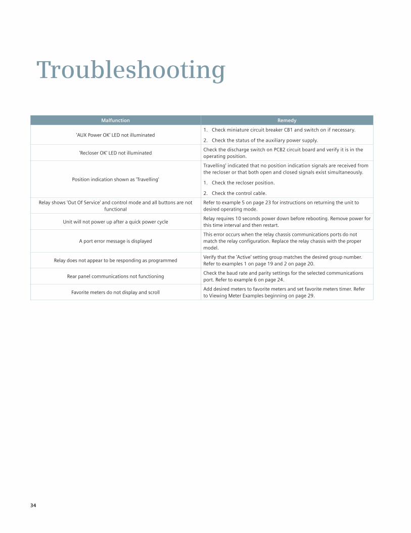
Troubleshooting
Malfunction Remedy
'AUX Power OK' LED not illuminated1. Check miniature circuit breaker CB1 and switch on if necessary.
2. Check the status of the auxiliary power supply.
'Recloser OK' LED not illuminatedCheck the discharge switch on PCB2 circuit board and verify it is in the operating position.
Position indication shown as 'Travelling'
Travelling' indicated that no position indication signals are received from the recloser or that both open and closed signals exist simultaneously.
1. Check the recloser position.
2. Check the control cable.
Relay shows 'Out Of Service' and control mode and all buttons are not functional
Refer to example 5 on page 23 for instructions on returning the unit to desired operating mode.
Unit will not power up after a quick power cycleRelay requires 10 seconds power down before rebooting. Remove power for this time interval and then restart.
A port error message is displayedThis error occurs when the relay chassis communications ports do not match the relay configuration. Replace the relay chassis with the proper model.
Relay does not appear to be responding as programmedVerify that the 'Active' setting group matches the desired group number. Refer to examples 1 on page 19 and 2 on page 20.
Rear panel communications not functioningCheck the baud rate and parity settings for the selected communications port. Refer to example 6 on page 24.
Favorite meters do not display and scrollAdd desired meters to favorite meters and set favorite meters timer. Refer to Viewing Meter Examples beginning on page 29.

35
Notes

The information provided in this document contains merely general descriptions or characteristics of performance which in case of actual use do not always apply as described or which may change as a result of further development of the products. An obligation to provide the respective characteristics shall only exist if expressly agreed in the terms of contract.
All product designations may be trademarks or product names of Siemens AG or supplier companies whose use by third parties for their own purposes could violate the rights of the owners.
Subject to change without prior notice. Order No.: E50001-F710-A410-X-4A00 All rights reserved. Printed in USA © 2012 Siemens Industry, Inc.
Siemens Industry, Inc. 7000 Siemens Road Wendell, NC 27591
For more information, contact: +1 (800) 347-6659
www.usa.siemens.com/reclosers