Embed Size (px)
Citation preview
7/30/2019 Trailers That Won't Steer You Wrong_tcm77-1306016
http://slidepdf.com/reader/full/trailers-that-wont-steer-you-wrongtcm77-1306016 1/4
As beam sections have becomemore structurally efficient,they also have become moreslender. Reducing their bulk
has reduced their weight, so much longerspans can be designed. In fact, 130- to 140-foot bulb-T beams and I-girders are beingused frequently. The length of bridgebeams now is limited mainly by the modeof transportation and allowable grossweight rather than by span restrictions. To transport these long girders over
roads and position them around the jobsite,producers often are turning to steerabletrailers. These trailers increase maneuver-ability, with some having a turning radiusas low as 20 degrees.
Steerable trailers offer many configurationsdepending on the size and the weight of theload. A typical configuration includes a low-boy or flatbed trailer attached to the tractor.
This trailer holds the front bunk, a detach-able piece of the steerable trailer system onwhich the front of the beam is mounted. Akingpin attaches the front bunk to a riser
which holds a fifth wheel. This connectionallows the front bunk to swivel and the endof the beam to rotate during a turn, just as atrailer rotates when a tractor-trailer makes aturn. The riser must distribute the weightover the trailer properly. The riser normallyis attached to the trailer by chaining andbolting it to the trailer bed. On the backend, the beam is supported by the steerabletrailer, which may have two, three, or asmany as five axles. For shorter loads thefront bunk can mount directly on the fifth
wheel of the tractor, eliminating the needfor the lowboy or flatbed and riser. Produc-ers commonly haul beams as long as 155feet using the first configuration, and as longas 125 feet with the bunk mounted directlyon the fifth wheel of the tractor. Mountingthe bunk directly on the tractor’s fifth wheelis beneficial since you are able to shortenthe overall length of the transporter.
Design considerations for shippingDuring shipping, a member may be sub-
jected to the most severe stress conditions
expected throughout its life. Long, slendersections even have collapsed whenshipped without the proper precautions. Abeam’s lateral stability is of more concernduring construction than in the finishedstructure when the beam is integrated intothe deck. But because many designers con-sider only the stability in the finished struc-ture, evaluating loads on the member dur-ing shipment and construction is left to theproducers and contractors.
Most lateral stability problems with longconcrete I-beams are caused by the beam’s
rolling sideways when lifted or transported.Extensive research into lateral stability wasreported by Robert Mast [Ref. 1 and 2]. Mastconcluded that when beams are transported,superelevation of the road and flexibility of the vehicle’s springs cause lateral deflectionof the beam. When lifted, long beams rolldue to tolerances in sweep and lifting loop
Loadingandhaulinglongbridgegirderswithsteerabletrailers
By Timothy S.Fisher
Trailers that won’tsteer you wrong
Figure 1. When lifting or supporting a beam from each end, it is able to roll anddeflect laterally.
7/30/2019 Trailers That Won't Steer You Wrong_tcm77-1306016
http://slidepdf.com/reader/full/trailers-that-wont-steer-you-wrongtcm77-1306016 2/4
placement (See Figure 1). Thesetolerances cause the center of gravity of the beam to be slightlyto one side of the roll axis—animaginary line connecting the lift-ing points.
Some producers and trans-porters assume that a beamshould be supported at each end
during transporting, as it will bein the finished structure. Howev-er, locating the lifting loops andthe support points on the truckand trailer even a small distancein from the ends of the beamserves to counteract rolling andcan dramatically improve the lat-eral bending stability.
Another benefit of moving thesupport points in from the endsof the beam when trailering is thereduction in overall length. Mastoffers equations to calculate thefactor of safety against failurewhen lifting and transporting. Upto a point, this factor of safety in-creases as the supports move far-ther from the ends.
When loading the beam ontothe trailers, you should place thesupport points on the trailer be-low the lifting loops. However,some deviation in location of support points is permissible. Asa rule of thumb, one transporteruses one to two times the depthof the member to determine howfar from the beam ends to locatethe support points.
When supporting the beams infrom the ends, evaluate the mem-
ber to confirm that the top fiberstresses of the cantilevered endsremain in compression. Fortunate-ly, long concrete girders normallyhave top compression and can tol-erate short cantilevers. To preventcracking, tensile stresses in the topflange can be counteracted bymild steel reinforcement or pre-stressing steel.
Imper and Laszlo (Ref. 3) rec-ommend temporarily post-tension-ing the top flange during handling
and shipment, if it is found thatthe top flange will be in tension.
To do so, run strands throughgreased plastic tubes in the topflange and anchor them with steelplates at each end. Once the beamis put in place, release the stressin the strands with hydraulic jacksor burn the strand through a small
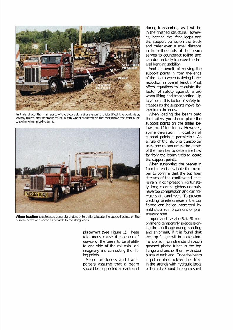
When loading prestressed concrete girders onto trailers, locate the support points on thebunk beneath or as close as possible to the lifting loops.
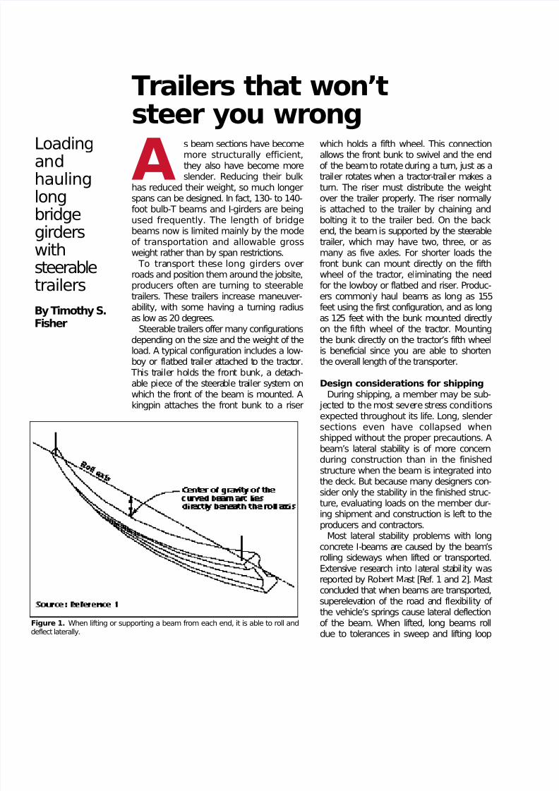
In this photo, the main parts of the steerable trailer system are identified; the bunk, riser,lowboy trailer, and steerable trailer. A fifth wheel mounted on the riser allows the front bunkto swivel when making turns.
7/30/2019 Trailers That Won't Steer You Wrong_tcm77-1306016
http://slidepdf.com/reader/full/trailers-that-wont-steer-you-wrongtcm77-1306016 3/4
hole provided near one end. Once re-laxed, the strand can be removedmanually from either end. Conven-tional reinforcing steel can also beplaced at each end to resist the ten-sion caused by the overhang.
Mast and also many producers whohave evaluated their beams foundthat sections of ordinary proportionshave sufficient strength to resist thebending and tilting caused by mosttransporting equipment (as depictedin Figure 1). When a failure oc-curred, it was most likely precededby something else such as breakingchains or pins, or the vehicle’s rollingover.
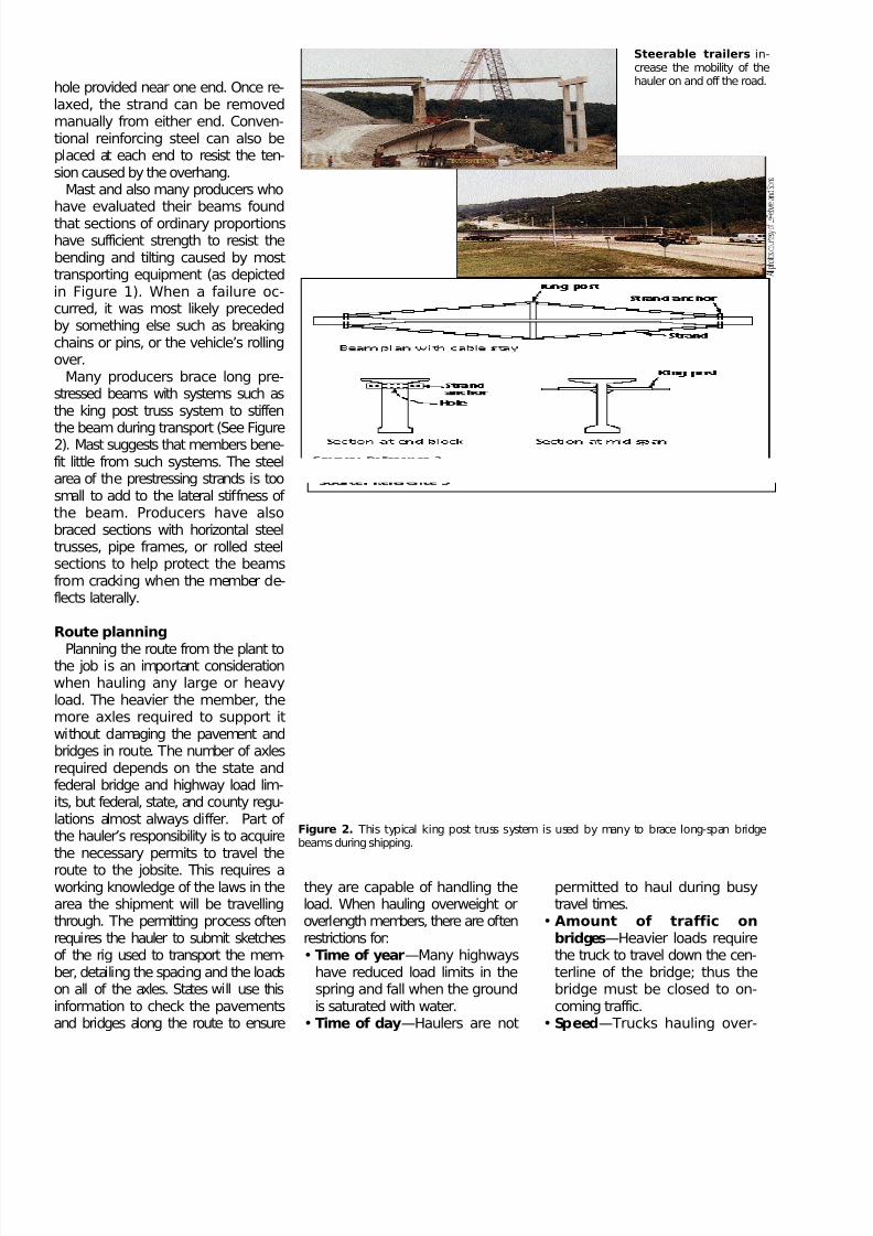
Many producers brace long pre-stressed beams with systems such asthe king post truss system to stiffen
the beam during transport (See Figure2). Mast suggests that members bene-fit little from such systems. The steelarea of the prestressing strands is toosmall to add to the lateral stiffness of the beam. Producers have alsobraced sections with horizontal steeltrusses, pipe frames, or rolled steelsections to help protect the beamsfrom cracking when the member de-flects laterally.
Route planning
Planning the route from the plant tothe job is an important considerationwhen hauling any large or heavyload. The heavier the member, themore axles required to support itwithout damaging the pavement andbridges in route. The number of axlesrequired depends on the state andfederal bridge and highway load lim-its, but federal, state, and county regu-lations almost always differ. Part of the hauler’s responsibility is to acquirethe necessary permits to travel the
route to the jobsite. This requires aworking knowledge of the laws in thearea the shipment will be travellingthrough. The permitting process oftenrequires the hauler to submit sketchesof the rig used to transport the mem-ber, detailing the spacing and the loadson all of the axles. States will use thisinformation to check the pavementsand bridges along the route to ensure
Steerable trailers i n-crease the mobility of thehauler on and off the road.
Figure 2. This typical king post truss system is used by many to brace long-span bridgebeams during shipping.
they are capable of handling theload. When hauling overweight oroverlength members, there are oftenrestrictions for:• Time of year—Many highways
have reduced load limits in thespring and fall when the groundis saturated with water.
• Time of day—Haulers are not
permitted to haul during busytravel times.
• Amount of traffic onb r i d ges—Heavier loads requirethe truck to travel down the cen-terline of the bridge; thus thebridge must be closed to on-coming traffic.
• Sp e e d—Trucks hauling over-
7/30/2019 Trailers That Won't Steer You Wrong_tcm77-1306016
http://slidepdf.com/reader/full/trailers-that-wont-steer-you-wrongtcm77-1306016 4/4
PUBLICATION #J960298
Copyright ©1996, The Aberdeen GroupAll rights reserved
weight loads must travel at aslower speed, especially overb r i d ges.
Operating trailersMany drivers say that operating
the trailer becomes second-natureafter some experience. The steer-able trailer normally houses itsown hydraulic power source sepa-rate from that of the tractor.Heavy-duty hydraulic cylindersmounted ahead of the swivel pointturn the axle assembly. The drivercontrols the trailer from the tractorcab.
One steering system is controlledby a two-button control box.Pressing one button extends thehydraulic cylinder to swivel thetrailer; the other button turns the
trailer in the opposite direction. Tostraighten out the trailer after com-pleting a turn, the driver depressesthe opposite button until the traileris running true. Drivers can tellwhen the trailer is not running par-allel with the tractor because thetrailer will pull to one side. Aquick tap of the control button willreturn the trailer to runningstraight.
Once unloaded, the steerable
trailer unit can be loaded on theflatbed or attached to the tractor if aflatbed is not being used for thehaul back to the yard. With atten-tion to details, steerable trailers canbe used to safely transport longconcrete members from the pointof production to their final restingspot.2
For more information on steer-able trailers, circle 101 on thereader service card.
References1. Mast, R. F., “Lateral Stability of Long Prestressed Concrete Beams -Part 1,”PCI J ournal, V. 34, No. 1,
January-February, 1989, pp. 34-5 3 .
2. Mast, R. F., “Lateral Stability of Long Prestressed Concrete Beams -Part 2,”PCI J ournal, V. 38, No. 1,
January-February, 1993, pp. 70-8 8 .
3. Imper, Richard R., and GeorgeLaszlo, “Handling and Shipping of Long Span Bridge Beams,” P C I
J ournal, V. 32, No. 6, November-December 1987, pp. 86-101.


![CARGOPRO TRAILERS [BRAND CATALOG] · PDF filecargopro contents [contents] 02 sprint utility trailers 3 standard utility trailers 4 landscape utility trailers 5 hd deckover utility](https://img.pdfslide.us/doc/110x75/5a785d9c7f8b9a77438bd82f/cargopro-trailers-brand-catalog-cargopro-contents-contents-02-sprint.jpg)