Embed Size (px)
Citation preview

for Small Properties
Mel BaughmanTerry Serres
Copyright © 2006Item #08425
9 >781888 440324
ISBN 1-888440-32-5
TrailDesign
TrailGuideCoverWebOnly.ps - 10/5/2006 8:12 AM

rail Design for Small Properties provides simple, inexpensive solutions
for designing, building, and maintaining sustainable trials—trails for
hiking, horseback riding, bicycling, cross-country skiing, snowmobiling,
off-highway motorcycles (OHMs), and all-terrain vehicles (ATVs).
If designed with sustainability in mind, a recreational trail can provide
years of enjoyment. Sustainable trails require minimal maintenance
because their design and materials hold up to intensive recreational use
and severe weather conditions.
What kind of tread material is best for your trail? Do you need a bridge to
cross open water or will stepping stones do? What tools do you need? We
answer these questions and more, providing the information you need to
make the right choices for your trail.
Acknowledgments
Authors: Mel Baughman is Associate Dean and ExtensionForester in the College of Food, Agricultural and Natural Resource Sciences at the University of Minnesota.
Terry Serres is a graduate student in Natural Resources Science and Management at the University of Minnesota.
Editor/Design: Julie RolesIllustration: John Molstad
Table of Contents
Determine Trail Uses 1
Select the Corridor 1
Establish Design Standards 4
Mark Trail Location 8
Clear the Trail 8
Construct the Tread 8
Install Structures 11
Sign the Trail 24
Install Facilities 26
Appendix A:
Tools for Trail Building 27
T
TrailGuide.ps - 9/19/2006 8:16 AM

Determine Trail UsesThe first step in trail design is to determine how the trail willbe used, how much it will be used, and what quality of userexperience you want to offer.
Multi-use or single-use? Multi-use trails work if: � There are many primary users but only a few secondary users.� The trail is used in different seasons by different users. � The trail is designed and maintained to accommodate all
users, or the trail is divided into parallel treads.� Clear rules are posted about how to behave (pass, regulate
speed, etc.) when encountering other types of trail users.
Consider a single-use trail if:� Different types of users have different levels of tolerance
for noise, effort in using the trail, speed of travel, or influence on the tread.
� You want to offer a high quality trail experience for onetype of user.
How much use? How much will the trail be used at any one time, day, seasonor year? As trail use increases:
� Increase tread and clearing width. � Create a more durable tread.
What quality of experience? Design your trail to fit the user experience that you want tooffer. Consider:
� Physical ability of trail users. For example, reduce trailgrade if you want to accommodate people with a range of physical abilities.
� Exposure to personal risk (e.g., injury, getting lost) the trail offers.
� Duration of the experience. Is it 30 minutes or 3 hours?� Purpose for the trail. If the trail simply leads to a destina-
tion, choose the shortest and easiest route. If the trail itselfis the destination, choose the most interesting route.
Trail Design for Small Properties � 1
Perhaps the most enjoyable step in trail design is exploringthe corridor to determine where to place the trail. A trail cor-ridor is a wide swath through the landscape that encompassesthe trail. Analyze the entire area, refining the trail location asyou gather more information.
Use Photos and MapsAerial photographs help you identify land uses on your prop-erty and neighboring properties (e.g., cropland, pasture, forest, river, lake), roads, trails, buildings, and utility rights-of-way (fig. 1). Look for photos in a scale of at least 4˝ to 1mile, but preferably 8˝ to 1 mile. Photos are often availablefrom the state department of natural resources, especially thestate forestry agency; U.S. Department of Agriculture, FarmService Agency; U.S. Geological Survey; and Web sites.
Topographic maps (1:24,000 scale) are helpful in hilly andmountainous terrain, especially if your trail covers a large
geographic area (fig. 2). They show elevation changes, forestand open areas, rivers, lakes, wetlands, buildings, roads,trails, cemeteries, and other features. Topographic maps maybe available from the U.S. Geological Survey, commercial CDsand DVDs, map dealers, and recreational outfitters.
Soil maps and accompanying data tables describe thesuitability of soil types for roads, structures, farming, forestry,etc. (fig. 3). Soil maps may be available from your local soiland water conservation district, USDA Natural ResourcesConservation Service, county Extension office, or Web sites.
When evaluating large sites, other maps or geographic infor-mation systems may provide information on water resources,rights-of-way, utilities, land uses, roads, land ownership, vege-tation cover types, wildlife habitat, flood zones, etc. Possiblesources include state or national natural resources agencies,local planning and zoning authority, and universities.
Select the Corridor
TrailGuide.ps - 9/19/2006 8:16 AM

Scout the Trail CorridorScout the corridor in the trail’s primary season of use. Toclearly see landscape details, scout when deciduous trees havelost their leaves. If possible, scout in all seasons to revealattractive features and hazards that may affect location, construction, or maintenance. Look for:
� Spring: high water, ephemeral ponds, flowers� Summer: dense foliage, normal water level� Fall: foliage color� Winter: icicles, snow scenes, frozen water
Note existing trails and roads, control points, obstacles,points of interest, and anchor points (fig. 4). Take notes andmark locations on a map or record GIS coordinates.
� Existing trails and pathways. Existing trails and roadsmay be good links to new trails. Also look for natural path-ways that require little clearing or construction (e.g., aridge top, hillside bench, or river bank terrace).
� Control points. Control points are physical or legal con-straints on a trail’s location. Ownership or managementunit boundaries, a steep slope forcing a trail through a nar-row section of hillside, a cliff that forces a trail around oneend, a wetland forcing the trail along a narrow upland ridge,or a stream that can be crossed easily in only a few placesare examples of control points.
� Obstacles. Obstacles can include a steep slope, rocky soil,boulder field, rock slide, sand dune, cliff, rock ledge, erod-ing bank, steep-sided gully, gorge subject to flash floods,water body, wetland, habitat for rare species, historic andcultural sites, fence, highway, sources of objectionablesound, and objectionable views. Obstacles may requireexpensive crossing structures.
� Points of interest. Run your trail past significant pointsof interest, e.g., unusual landforms (sink hole, esker, sanddune, hill, valley, gorge); different forest types or ages; for-est opening; grassland; farm land, especially if it attractsfeeding wildlife; scenic vista; boulders; rock outcrop; wet-land; ephemeral pond; lake; river; creek; waterfall; historicsite (may also be an obstacle); archeological site (may alsobe an obstacle); and wildlife habitats (den trees, rock piles,dense thickets, layers of forest vegetation, water sources,sand banks, cliffs, caves, crevices). Attract wildlife to thetrail corridor with nesting boxes, breeding sites, food plots,feeding stations, roost poles, watering devices, and otherconstructed habitats.
� Anchor points. At frequent intervals, take the trail pastsubtle anchor points (e.g., large or unusual tree, rock,patch of shrubs) that add interest and draw attention tolandscape features.
2
Figure 2. A topographic map shows elevation. The more closelyspaced the lines, the steeper the slope.
Figure 3. Match numbers on a soil map to written descriptions ofsoil capability and limitations.
Figure 1. An aerial photograph helps identify land uses.
TrailGuide.ps - 9/19/2006 8:16 AM

Additional Points to Consider � Avoid placing your trail in areas with threatened or endan-
gered flora, fauna, geology, and natural plant communities.Ask your state’s department of natural resources whetherthese resources exist or are likely to be found on or nearthe trail location.
� Protect cultural resources such as historic structures (build-ings, dams, bridges, fire towers, etc.), archaeological sites(above and below ground), cemeteries (including unplattedhistoric cemeteries, burial mounds, and other ancient buri-als), and traditional-use areas where natural resources aregathered for food, medicine, or ceremonial uses. Culturalresources can be damaged by soil disturbance, soil com-paction, rutting, change in public access, and change invegetation and other features. Whenever a governmentpermit, license, or funding is needed for a project, a
cultural resources management review may be required. To learn about locations of cultural sites, contact a statearchaeologist.
� Discuss your trail project with neighbors to learn about theimpact on their properties and potential linkages to othertrail systems.
� Consider your budget for land and right-of-way acquisi-tion, construction, and maintenance. This will put a realitycheck on your design plans.
To Learn More � Contact your soil and water conservation district to learn
about rules affecting trails over streams and wetlands.� Contact the governing road authority to learn about rules
for trails that cross or follow roads.
Trail Design for Small Properties � 3
Point of interest:stand of large trees
Anchor point:boulders
Point of interest:old building
Anchor point:snag and den tree
Anchor point:brush pile
Point of interest:food plot
Obstacle: gully
Point of interest:overlook
Anchor point: shrubs
Point of interest:rock outcrop
Anchor points:trees
Control point: property line fence
Control point: river crossing
Existingdirt road
Figure 4. Consider existing roads and trails, control points, obstacles, points of interest, and anchor points in trail layout.
TrailGuide.ps - 9/19/2006 8:16 AM

After exploring the trail corridor, but before flagging the exacttrail location, set your design standards. Base the standardson the trail uses; the quality of experience you want to offer,including the level of risk; and your construction resources,including budget and expertise. Use the Recommended TrailDesign Standards on pages 6 and 7 as a starting point.Modify them to fit your needs.
Consider these aspects of the trail design: trail configuration,trail length, tread surface, tread width, clearing width, clear-ing height, grade, turning radius, sight distance, water cross-ings, and special requirements.
Trail configuration is the overall shape of the trail.
� Linear trails are appropriate for long distance travel (sev-eral miles) or where the land ownership (right-of-way) istoo narrow to permit development of a loop trail.
� Spur trails are short linear trails that take users to points of interest or connect different loop trails.
� Loop trails permit the user to begin and end at the samelocation without repeating any part of the trail.
� Stacked loop trails (a series of interconnected loops) permit users options for different distances, routes, ordestinations.
Trail length is the distance that users could travel in one day.
Tread surface refers to the type of surface material (e.g., soil,gravel, rock) and its condition (e.g., smooth, rolling, rough).High-use trails require more durable materials and smoothersurfaces than light-use trails.
Tread width is the width of the useable trail surface. In gen-eral, the tread width that is suitable for light-use or one-waytravel should be doubled for heavy-use or two-way travel.
Clearing width is the total width to which rocks, trees, treelimbs, and other obstacles should be removed. As a generalrule, clear at least 2´ on each side of the tread. Where a trailpasses through dense vegetation, vary the clearing width toavoid an unnatural tunnel effect. In general maintain clearingwidth from the ground up to the clearing height, except youmay leave vegetation, rocks, and other objects less than 2´ tallnear the tread edge. Center the tread within the clearing width,except on hillside trails where clearance may be less on thedownhill side.
Clearing height is the height above the tread surface towhich overhanging rocks, tree limbs, and other obstructionsmust be removed. As a general rule, clear 2´ above the user’shead. Keep in mind that leaves will bend deciduous treebranches 1–2´ lower in summer than in winter and snow willbend evergreen tree branches and raise the tread surface.
4
Treadwidth
Clearingwidth
Clearingheight
<2’
Figure 6. Tread width, clearing width, and clearing height.
Stacked loops
Loop
Linear trail
Spur
Figure 5. Trail configuration is the overall shape of a trail.
Establish Design Standards
TrailGuide.ps - 9/19/2006 8:16 AM

Grade is the slope angle (expressed in degrees or percent)along the trail’s centerline.
% grade = (degrees of angle) x (tangent)
It is easy for trail users to travel long distances on low grades.High grades require more work and should extend for shorterdistances. Measure grade with a commercial or homemadeclinometer (fig. 7).
Turning radius is the radius of an arc drawn through the cen-terline of the tread where the trail curves. As travel speedincreases, lengthen the turning radius, bank the trail higher onthe outside edge, widen the trail, or clear a runout zone (fig. 8).
Sight distance is the distance that a user can see down thetrail from any point on the trail. Adhere to the recommendedminimum sight distance, but vary sight distances to addinterest. Lengthen sight distance to allow faster travel andreduce sight distance to slow travel.
Water crossings refer to the type of structures recom-mended for crossing bodies of water. A ford, stepping stones,culvert, boardwalk, or bridge may be appropriate. Yourchoices will be affected by the type of user, type of experienceyou want to offer, type of water body, length of crossing, legal status of the water body, your ingenuity, and your budget.
Trail Design for Small Properties � 5
Make a clinometer with a protractor, short string, and small weight.
To measure grade:1. Sight along the protractorÕs flat edge and read the degree
aligned with the string.
2. Determine the slope angle:
90˚ – (angle read on protractor) = slope angle in degrees
Example: 90˚ – 80˚ = 10˚ slope
To convert degrees of slope to percent slope:1. Look up the tangent of the slope angle in degrees on a scientific
calculator or in a tangent table in a book.
2. Determine the percent of slope:
Tangent (of slope angle in degrees) x 100% = % slope
Example: Tangent (10˚) x 100% = 0.176 x 100% = 17.6 or18% slope
Figure 7. How to use a clinometer.
15’
Trail down
Long
Short
Trail down
Runout
Trail down
6’
6’
Increase turning radius Bank outside edge
Widen trail Clear runout
H
Stringand weight
Read anglein degrees
Line of sight
Line of sightSight the targetat eye level
H
Protractor
Making and Using a Clinometer
Figure 8. Design options for safer turns, especially on steep slopes.
TrailGuide.ps - 9/19/2006 8:16 AM

6
Table 1. Recommended design standards for various types of recreational trails.
Recommended Trail Design Standards
Trail Use Configuration Length Tread Surface Tread Width Clearing WidthClearingHeight
Hiking Loop or multiple loops forday hikes; variety inlandscape; frequent curvesand grade changes; spurtrails to points of interest
5–15 mi Mineral soil, embedded rocks,bedrock, asphalt, or concrete
2–3 ft light useor 1-way, 4–6 ftheavy use or2-way
4–6 ft light useor 1-way, 6–10 ftheavy use or 2-way
8 ft
Horse Loop or multiple loops withvariety of scenery andterrain, and open paradearea; 1-way traffic; avoidwater and road crossings;avoid wet areas and steepslopes where it is difficult tomaintain tread
5–25 mi Mineral soil; crushed,compacted gravel
2–4 ft light useor 1-way, 6–8 ftheavy use or2-way
8 ft light use or1-way, 12 ftheavy use or2-way
10 ftminimum,12 ftpreferred
Touring Bike
Loops and linear trails; 1-waytraffic
5–50 mi Limestone fines; othercrushed stone 3/8” or less; 2”asphalt over 3–4” base ofcompacted gravel
3–6 ft light useor 1-way, 8–10 ftheavy use or2-way
8 ft light use or1-way, 10–14 ftheavy use or2-way
8–10 ft
MountainBike
5–20 mi Mineral soil, bedrock 2–3 ft 6–8 ft
Cross-Country Ski
Loop or multiple loops(always); 1-way traffic best;2-way okay on access trail,but provide separate uphilland down-hill segments onslopes over 8%; north- andeast-facing slopes retainsnow longer
4–10 mi Remove rocks, logs, stumpsfrom tread; maintainvegetation to hold snow;groom when snow 6–12”deep
5–6 ft light useor 1-way, 8–10 ftheavy use or2-way
8 ft light use or1-way, 12–14 ftheavy use or2-way
8 ft aboveexpectedsnow depth
Snowmobile Cross steep contours at rightangles; avoid steep hillsideswith rollover risk; 1-waytraffic except on access trails;if 2-way, provide separateuphill and downhill segmentson slopes over 8%
5–50 mi Remove rocks, logs, stumpsfrom tread; maintainvegetation to hold snow;hard surfaces promotemelting but asphalt orconcrete okay where snowfallis sufficient; groom heavilyused trails
8–10 ft light useor 1-way,10–14 ft heavyuse or 2-way
8–12 ft light useor 1-way,14–16 ft heavyuse or 2-way
8 ft aboveexpectedsnow depth
All-TerrainVehicle (ATV)
Trail system with loops ofvarying difficulty, easy trailsprovide access to moredifficult trails; 2-way trails;occasional obstacles
5–20 mi. Mineral soil, bedrock, looserocks less than 6” diameter
5–7 ft light useor 1-way, 8–12 ftheavy use or2-way
6–10 ft 8 ft
Off-HighwayMotorcycle(OHM)
5–50 mi. Mineral soil, bedrock, rocksfirmly embedded in treadsurface
1.5–2 ft light useor 1-way, 3–6 ftheavy use or2-way
6–8 ft 8 ft
TrailGuide.ps - 9/19/2006 8:16 AM

Trail Design for Small Properties � 7
Grade Turn Radius Sight Distance Water Crossing Other Uses Unique Facilities
1–7% preferred, 10%maximum sustained,40% for shortdistances
Not critical, but 6 ftpreferred
Not critical,but 50 ftrecommended,especially atroad crossings
Stepping stones or ford if water lessthan 2 ft deep; culvert or bridge, 3–4ft wide for light use, 5–6 ft for heavyuse; at least one handrail if bridge ishigh-use, more than 12 ft long, ormore than 4 ft over water
Low-usehorseback riding,snowshoe, cross-country ski,snowmobile
Resting benches
1–10% preferred, 10%maximum sustained,20% for shortdistances
6 ft 50 ft minimum,100 ft preferredand at roadcrossings
Ford slow-moving water less than 3 ft deep—select site w/ stable sandor gravel base; soil-covered culvert isbetter than bridge; bridge only ifwater is deep and swift, must bewell-designed
Hiking; if nowinter riding:snowmobile,cross-country ski,snowshoe
Parking with trailerspace, tether line;campsites withtether lines orcorrals, water,manure dump
0–3% preferred,5–10% maximumsustained, 15% forshort distances
Radius in feet = (1.25 x velocity inmph) + 1.5
50 ft minimum,100 ft at roadand watercrossings and on2-way trails
Culvert, bridge, or boardwalk w/handrails; orient deck boards45–90º to direction of travel; width4–8 ft for light use or 1-way, 10 ftfor heavy use or 2-way
Hiking, off-season cross-country ski,snowshoe,snowmobile
Bike rack
4 ft minimum, 8 ftpreferred
(Varies by skill level):0–5% preferred, 10%maximum sustained,25–40% max. forshort distances andexperts; break steepclimbs with short,level resting places;make end of downhillslopes straight andlevel or gently rising
50 ft minimum, 100 ftpreferred; avoidcurves at foot ofdownhill slopes, orprovide warning 100ft before enteringcurve and runoutzone, widened trail,or wider turningradius
50 ft minimumon steepdownhill runs orwhen crossingroads, water-ways, or hazards
Straight, 0–5% grade onapproaches; culvert, bridge, orboardwalk w/ handrails; width 6–10 ft, bridge and boardwalk decks flush with tread surface,boards spaced 3/8”or less to holdsnow; frozen water crossings only on narrow, shallow (< 12"), early-freezing streams and wetlands
Snowshoe; off-season hiking,OHM, ATV,mountain bike,horse
Resting benches atregular intervals,shelter every 8–12miles
0–25% preferred, 25%maximum sustained,40% for < 50 yards
50 ft minimum,100 ft preferred(depends on speed)
50 ft minimum,100+ ftpreferred(depends onspeed)
Straight, 0–5% grade on approaches;culvert, bridge, or boardwalk; width8–10 ft, bridge and boardwalk decksflush with tread surface, boardsspaced 3/8” or less to hold snow;reflective markers on corner posts atbridge ends; frozen water crossingsonly on narrow, shallow (< 12”),early-freezing streams and wetlands
Off-season horseriding, hiking,mountain bike,OHM, ATV
Parking with trailerspace, open areanear entrance towarm up snow-mobiles; rest stopsor shelters after 15 miles
0–25% preferred, 25%maximum sustained,45% for < 100 yards
10 ft minimum,25 ft maximum
50 ft minimum,100 ft preferred
Culvert, bridge w/ handrails, orboardwalk w/ curbs; orient deckboards 45–90º to direction of travel;width 4–8 ft for light use or 1-way,10 ft for heavy use or 2-way
Mountain bike,snowmobile;OHM
0–30% preferred, 30%maximum sustained,50% for < 100 yards
4 ft minimum,10 ft maximum
50 ft minimum,100 ft preferred
Culvert, bridge w/ handrails, orboardwalk w/ curbs; orient deckboards 90º to direction of travel;width 4–6 ft for light use or 1-way,10 ft for heavy use or 2-way
Mountain bike,ATV, snowmobile
Parking with trailerspace, warm-uploop; rest stops or shelters after 15 miles
TrailGuide.ps - 9/19/2006 8:16 AM

Construct the TreadCreate a tread surface that is smooth and durable enough forintended users. Save effort by placing the trail on soils thatwithstand trail use.
Select Tread MaterialsConsider how tread materials will react to compaction, dis-placement, and erosion. (See Tread Materials, pages 9–10, forstrengths and weaknesses of different materials.)
• Compaction comes from the downward force from feet,hooves, wheels, etc. When a tread is fully compacted, itholds its shape and resists displacement and erosion.Compact the tread as much as possible during initial con-struction. Some materials have better compaction proper-ties than others. Tread materials that do not compact (e.g.,sand, organic soil, water-saturated soil) or that compacttoo much (e.g., peat) will not retain a desired shape.Excessive compaction tends to lower the tread and encour-ages water to collect in depressions.
• Displacement is sideways force that moves tread materialoff the trail, raising trail edges over time. Displacementalso lowers the tread, enabling water to collect in depressions.
• Water and wind erosion remove tread material, destroyingthe tread. The potential for erosion from running waterincreases as the slope and/or volume of water increases.
If possible, use materials for the tread from the immediatesurroundings. Natural materials are inexpensive and blendwell with the landscape.
Consider hardening the tread with rock, pavers, or othermaterials as a last resort when:
� Drainage is poor and mud is a problem.� Flowing water causes unacceptable erosion.� Tread material compacts or displaces too much to retain
the desired tread shape over the long term.� Tread must be narrow and clearly delineated to protect the
surrounding area.
Mark Trail LocationAs you mark the trail, keep your design standards in mind.
1. Mark the centerline of the trail using one of these materials:� Rolls of plastic flagging (tie 15˝ strips to branches).� Wire flags (stiff wire, 2´ or longer, with plastic flag).� Wooden stakes (12–18˝ or longer) topped with
brightly colored flagging or paint.
Space the markers approximately 20´ apart in dense vege-tation and up to 100 yards in open fields. Write cumulativedistances on markers every 100´ to make it easy to matchmarkers with trail maps and notes.
2. Map the route. Use a global positioning device or a com-pass and distance measurements to develop a trail map.Mark structures and special instructions on the map. Make special note of places that require deviations fromtrail standards. Photograph sites where trail structures areneeded to assist in planning materials and equipment or to show potential contractors what these sites look like.
3. Obtain permits for crossing streams, wetlands, railroads,highways, rights-of-way, etc.
Begin constructing the trail soon after flagging, before markers are moved or damaged.
8
Clear the TrailClear the trail in these stages:1. Remove small trees, shrubs, and limbs from large trees.2. Cut large trees.3. Remove stumps and boulders.4. Move soil to level the tread.
The extent of clearing needed depends on the clearing heightand width of the trail, the quality of the user experience (e.g.,a rough, challenging trail or a smooth, easy trail), and the pri-mary season of use (e.g., snow will cover some obstacles inwinter). (See Appendix A: Tools for Trail Building.)
TrailGuide.ps - 9/19/2006 8:16 AM

Trail Design for Small Properties � 9
Continued on page 10
BedrockIf a feature of the site, smooth bedrock makes a verydurable tread. It can be slippery for horses, especially onslopes. Avoid using bedrock where snow retention isdesirable. Sites with vegetation retain snow longer.
SoilMineral soil is composed primarily of sand (0.05 to2.0 mm—coarse texture), silt (0.002 to 0.05 mm—medium texture), and clay (0.002 mm—fine texture). Soilwith a high percentage of silt, moderate percentage ofsand, and small percentage of clay makes a very durabletread. Such a soil resists excessive compaction and erosionwhile allowing internal drainage.
Soil composed mainly of sand will not erode with water orbecome muddy but, because sand does not compact, it issubject to displacement and wind erosion. Soil with ahigh clay and silt content is subject to water erosion andmud. Soil composed mainly of clay retains water and canbe muddy and slippery when wet and, unless it is highlycompacted, it is also subject to water erosion.
Organic soil (humus) is composed of decomposing plantmaterials. Soil composed mainly of decomposed organicmaterial will compact and erode, and can become watersaturated and muddy. It is not desirable for trails andlikely will need artificial hardening (e.g., boardwalk)unless the trail receives light, low-impact use only whendry or frozen. Soil composed mainly of undecomposedorganic material, such as peat, compacts too much to besuitable as tread material.
VegetationTry to maintain natural vegetation (primarily grass) forhikers and horses, and for snow retention for skiing,snowmobiling, or snowshoeing. Vegetation survives beston a lightly used trail in full sunlight. Vegetation is diffi-cult to sustain in sandy soil (which is dry and nutrientpoor), on steep slopes (where there is more abrasion fromtrail users and erosion), and in deep shade.
Duff is undecomposed organic matter (e.g., leaves, twigs,moss, pieces of bark and wood) that litters a forest floor.Duff does not compact well and is easily displaced.
For shaping during construction, remove duff from thetread to expose the ground surface. However, a light dufflayer can help soak up moisture and break the erosiveforce of rainfall. If a natural surface is desired, you maychoose to allow duff to accumulate on a finished trail.
Wood ChipsUse wood chips to define the tread on newly constructedfoot trails, to suppress vegetation growth, and to raise thetread in muddy areas. Apply a 3–4˝ layer of large woodchips that do not contain leaves or small diameter twigs(which decay rapidly). Hauling and spreading wood chipsrequires extensive labor, and wood chips need to bereplaced every three years as they decay or are displaced.In most situations, wood chips should be a temporarytread material.
RockRocky material includes gravel (from sand to 3˝diameter), cobbles (3–10˝ ), stones (10–24˝ ), or boulders (greater than 24˝ ).
Rocks are useful on trails that receive heavy use, especiallyby horses or heavy motorized vehicles, or where a veryfirm, smooth tread is needed such as for touring bicyclesor wheelchairs. Rocky material resists excessive com-paction and displacement and provides a very strongtread. If protruding rocks are hazardous or too bumpy foryour quality standards, excavate rocks or chip off the pro-truding piece.
Crushed rocks compact and resist displacement betterthan rounded rocks (e.g., from beaches, river beds, andglacial till). Crushed rock made from hard rock is moredurable than from soft rock. A tread composed entirely ofrounded cobbles is prone to displacement, but whenembedded in clay, cobbles add durability to the tread. Ifused in a mixture of sizes including plenty of small parti-cles to fill voids, rocks interlock well. To achieve a smooth,firm surface, mix small gravel with rock dust from a com-mercial-scale rock crusher. For small jobs, haul a portablerock crusher to the work site. To produce a small quantityof gravel for chinking crevices, crush rocks with a sledge-hammer or the rounded end of a steel pry bar.
Tread Materials
TrailGuide.ps - 9/19/2006 8:16 AM
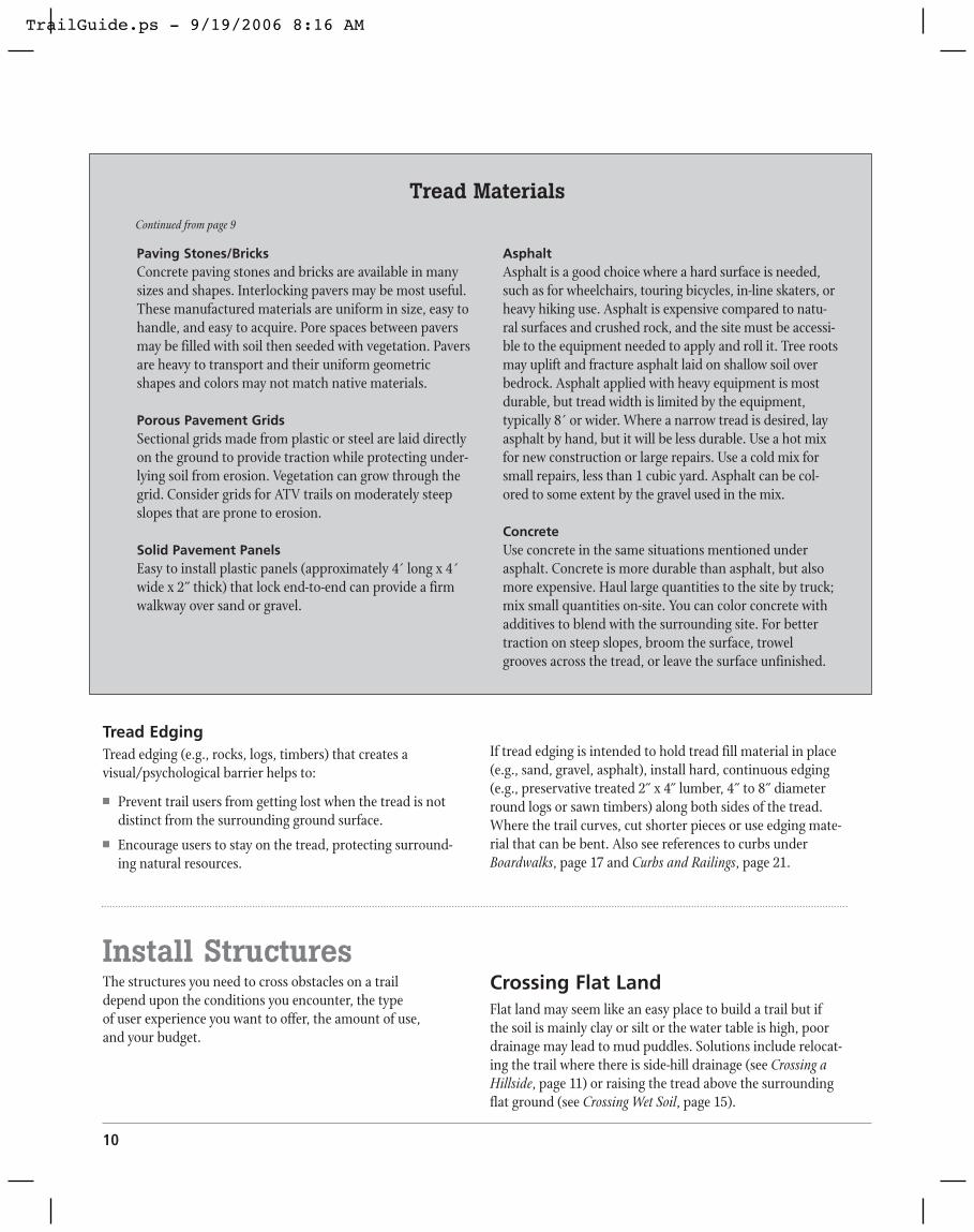
Tread EdgingTread edging (e.g., rocks, logs, timbers) that creates avisual/psychological barrier helps to:
� Prevent trail users from getting lost when the tread is notdistinct from the surrounding ground surface.
� Encourage users to stay on the tread, protecting surround-ing natural resources.
If tread edging is intended to hold tread fill material in place(e.g., sand, gravel, asphalt), install hard, continuous edging(e.g., preservative treated 2˝ x 4˝ lumber, 4˝ to 8˝ diameterround logs or sawn timbers) along both sides of the tread.Where the trail curves, cut shorter pieces or use edging mate-rial that can be bent. Also see references to curbs underBoardwalks, page 17 and Curbs and Railings, page 21.
10
Paving Stones/BricksConcrete paving stones and bricks are available in manysizes and shapes. Interlocking pavers may be most useful.These manufactured materials are uniform in size, easy tohandle, and easy to acquire. Pore spaces between paversmay be filled with soil then seeded with vegetation. Paversare heavy to transport and their uniform geometricshapes and colors may not match native materials.
Porous Pavement GridsSectional grids made from plastic or steel are laid directlyon the ground to provide traction while protecting under-lying soil from erosion. Vegetation can grow through thegrid. Consider grids for ATV trails on moderately steepslopes that are prone to erosion.
Solid Pavement PanelsEasy to install plastic panels (approximately 4´ long x 4´wide x 2˝ thick) that lock end-to-end can provide a firmwalkway over sand or gravel.
AsphaltAsphalt is a good choice where a hard surface is needed,such as for wheelchairs, touring bicycles, in-line skaters, orheavy hiking use. Asphalt is expensive compared to natu-ral surfaces and crushed rock, and the site must be accessi-ble to the equipment needed to apply and roll it. Tree rootsmay uplift and fracture asphalt laid on shallow soil overbedrock. Asphalt applied with heavy equipment is mostdurable, but tread width is limited by the equipment, typically 8´ or wider. Where a narrow tread is desired, layasphalt by hand, but it will be less durable. Use a hot mixfor new construction or large repairs. Use a cold mix forsmall repairs, less than 1 cubic yard. Asphalt can be col-ored to some extent by the gravel used in the mix.
ConcreteUse concrete in the same situations mentioned underasphalt. Concrete is more durable than asphalt, but alsomore expensive. Haul large quantities to the site by truck;mix small quantities on-site. You can color concrete withadditives to blend with the surrounding site. For bettertraction on steep slopes, broom the surface, trowelgrooves across the tread, or leave the surface unfinished.
Tread MaterialsContinued from page 9
Install StructuresThe structures you need to cross obstacles on a trail depend upon the conditions you encounter, the type of user experience you want to offer, the amount of use, and your budget.
Crossing Flat LandFlat land may seem like an easy place to build a trail but if the soil is mainly clay or silt or the water table is high, poordrainage may lead to mud puddles. Solutions include relocat-ing the trail where there is side-hill drainage (see Crossing aHillside, page 11) or raising the tread above the surroundingflat ground (see Crossing Wet Soil, page 15).
TrailGuide.ps - 9/19/2006 8:16 AM

Trail Design for Small Properties � 11
Crossing a HillsideA hillside trail must quickly drain surface water off the treadwhile maintaining its shape and a grade that is comfortablefor trail users. Options for crossing a hillside include full-bench and cut-and-fill trails, retaining walls, diverting wateracross the tread, and diverting water flowing down the tread.
Full-Bench and Cut-and-Fill TrailsA flat trail bed cut from a hillside provides a safe and comfort-able crossing for users. In a full-bench trail, the full width ofthe tread is cut from the hillside. A full-bench trail usually hasa well-compacted base because the underlying material hasbeen in place for thousands of years.
If part of the tread is built upon fill material that was cut fromthe hillside, it is a cut-and-fill trail. Fill material may be diffi-cult to compact, especially with hand tools. If fill material isnot well compacted, horses and vehicles may destroy thetread. If fill material must be used for part of the trail bed, use large rocks to form the trail bed and serve as edging, thencover them with tightly compacted soil.
Backslope is the area above a trail where material has been cutfrom a hillside in the process of leveling the tread. The back-slope grade necessary to prevent soil erosion depends on thematerial. A backslope of 1.5:1 (horizontal run: vertical rise) isadequate for stable materials whereas a backslope of 4:1 maybe needed on erodible materials.
Retaining WallsWhere a trail cuts across a slope and vegetation does not sta-bilize exposed soil above or below the tread, a retaining wallwill prevent soil erosion. A retaining wall below the tread maybe more durable than one along the backslope (perhapsbecause trail crews are more careful in building walls thatsupport the tread). Building a retaining wall to support thetread may negate the need for cutting into the backslope, thuspreserving natural vegetation that holds the soil. Tie wallsinto the embankment with a deadman (e.g., geotextile fabric,logs, or large rocks). Build walls without mortar or installdrain pipes to allow water to seep through the wall.
Trail tread
Cut
Fill
Backslope
Full-bench trail
Trail tread
Cut
Compactedfill
Backslope
Cut-and-fill trail
Figure 9. Full-bench and cut-and-fill trails provide safe travelacross steep slopes.
Secure with spikes.
Porousbackfill
Deadman
Wood retaining wall
Optional perforateddrain pipe
18” –24”
TOP VIEW
Deadman6” x 8” x 3’ timbers spaced 8’ apartalong wall
3–6” setbackper 12” rise
Trail tread
Stone retaining wall
12”
3–4’ wide fabric mat.Place every 8” of wall height in clay; every 12–24” in sand.
Continue faceat least 6” belowfinished grade.
24” min.
Trail treadPorous backfill
Stone rubble
Hard native stone
Top course shouldbe mortared.
3–6” setbackper 12” rise
Compact subgrade
Figure 10. On steep slopes, use walls to support the backslope or the tread.
TrailGuide.ps - 9/19/2006 8:16 AM

12
Outslopes and InslopesWhere a trail crosses a hillside with medium- to coarse-textured soil, outslope the tread to quickly drain off surfacewater. A 2–5% outslope is quite common and suitable formost trail users. In heavy rainfall areas, outslope up to 10%,provided trail users can safely negotiate this slope withoutslipping or rolling off the trail.
Some trail designers recommend no outslope on horse trails.Horses tend to walk on the outside edge of a tread and willcrumble the edge over time. A flat tread also is safer forhorses that may slip when the surface is wet. If you build aflat-cross-section trail, divert water from the tread usingrolling grade and waterbars (see below and page 13). On flat-cross-section trails that traverse steep slopes, you may wish tocreate an edge berm (raised shoulder), except at grade dips, toprotect the outside edge of the tread from erosion and to cre-ate a safer trail for users. Strengthen an edge berm with vege-tation or rocks.
Where a trail crosses a hillside that has fine-textured, erodiblesoil, inslope the tread to a ditch, then divert water in the ditchacross the trail and downhill through grade dips or culverts.
Divert Water Flowing Down the TreadWhere the tread has a relatively flat or concave cross-section,some water will run down the length of the trail. To preventsoil erosion, divert water off the tread with a rolling grade orwaterbars.
Rolling GradeA rolling grade divides the trail into narrow watersheds withundulating crests and dips like a gentle roller coaster. Waterdrains off at the dips. Ideally, no part of the tread is com-pletely level. Outslope the bottom of each dip and make theoutlet wide enough to drain off water without clogging.
Place tread dips at natural drainage ways and at other loca-tions as needed. Rolling grade is most appropriate when tra-versing hill slopes (fall lines) of 20–70%. On hill slopes less than 20%, water does not drain well at the dips.
Drainage dips can deposit sediment into waterways. Toreduce sedimentation, consider these alternatives: maintain alow tread grade on the approach to the drainage; design asmall tread watershed with a short slope toward the water-way; harden the tread; or maintain a nearly level tread andinstall a boardwalk, bridge, or culvert over the waterway.
Also use rolling grade to ascend/descend hillsides. In thosesituations, rolling grade is most effective when the treadgrade is less than 1/4 –1/3 of the hill slope. For example, if the
hill slope is 45%, the tread grade should not exceed15%, and 10% is preferred. As the trail climbs,
periodically reverse the grade downhill for afew steps to create a dip that allows water
to drain off.
Even when a trail is outsloped,insloped, or center-crowned, a rollinggrade is desirable. These cross-sec-tional shapes are difficult to sustainover long periods without substantialmaintenance.
Berm
Outslope
Inslope
Flat with berm
Figure 11. Outslope, inslope, and berm.
Outslope
Figure 12. A rolling grade uses undulating crests and dips todivert water off the tread.
TrailGuide.ps - 9/19/2006 8:16 AM

Trail Design for Small Properties � 13
Adjust the size of each tread watershed depending on thesefactors:
� When the watershed above the tread is large, increasingthe potential for runoff, make tread watersheds small.
� If the water infiltration rate of the upslope soil is slow,resulting in more potential runoff, make tread watershedssmall.
� If the potential for erosion is high, make tread watershedssmall. Hardening the tread, placing the trail beneath a treecanopy that will intercept precipitation and reduce splasherosion, or reducing tread width to minimize exposed soilwill also reduce risk of erosion.
� Where trail grade is steep, make tread watersheds small or reduce the trail grade by lengthening the trail or addingswitchbacks or turns. Tread erosion risk is relatively lowwhen tread grade is less than 5%, moderate when treadgrade is 5–10%, and higher when tread grade is greaterthan 10%.
� When hill grade is steep, make tread watersheds small.Tread dips drain best when there is a substantial differencebetween the tread grade and hill grade.
WaterbarsA waterbar is an obstruction placed across a trail tread todivert surface water off the tread. Waterbars may be neededon a sloping trail with a flat cross-section (no outslope) orwhere rolling grade is not adequate to divert water at treaddips. Because most waterbars create a significant bump in thetrail, they are not desirable on trails used for bicycling, skiing,or snowmobiling. A rubber waterbar can be used for bicycletrails. When waterbars are placed on horse trails, horses tendto compact the soil immediately above and below the waterbar leading to depressions that collect water and mud. Horsesalso can damage waterbars because of their weight andstrength. When used on horse trails, anchor waterbars well.
Place waterbars at a 30–45˚angle across a trail. Where heavyrunoff is expected, place stones at the outflow to dispersewater without causing soil erosion.
If a waterbar diverts water into a ditch, make sure the bardoes not protrude into the ditch where it might catch debrisand block the ditch.
Use judgment and experimentation in spacing waterbars.Closer spacing is needed where the trail grade is steep, the soilis erodible, or you want a high quality tread without theexpense of hardening materials.
Earthen waterbar
30–45º
Log waterbar
Drainage path
Pile soil to top of waterbar on downhill side. Hold log in place with stakes.
Rock waterbar
Rubber waterbar
Extend structure into cut bank 15” min.
Continuous rubberconveyor belting
Treatedtimber2”x 6”
2” min. fill
30d galvanized nails
41/2– 51/2”
21/2–31/2”
6”
Figure 13. Waterbars are another way to divert water off the tread.
TrailGuide.ps - 9/19/2006 8:16 AM

14
Climbing and DescendingSteep Slopes and Cliffs
SwitchbacksA switchback reduces trail grade by lengthening the trail in azigzag pattern. Design each trail segment to conform to thedesired grade as much as possible. Place a switchback wherethe trail reaches an impassable obstacle or begins to run toofar in the wrong direction. Avoid closely spaced switchbacksto discourage trail users from taking shortcuts, leading to ero-sion. To further reduce shortcuts, locate switchbacks at inter-esting focal points (e.g., conspicuous tree, boulder, or rockoutcrop) and place barriers (e.g., boulders, logs, thornybushes) in the cutoff zone. Build the switchback platformwith a 2–5% grade. On a very steep slope install a retainingwall to support the platform or install steps. If the main trailhas a substantially steeper grade than the platform, create atransition grade as the trail approaches the switchback plat-form. Divert surface water off the trail above the switchbackby means of inslope to a ditch. Design the switchback withthe correct turning radius for the intended users. Switchbacksmay not be practical for skiers and snowmobilers because ofthe long turning radius they require.
Fixed RopesOn a lightly used foot trail with a steep slope and soil thatbecomes slippery when wet, a rope can help hikers climb ordescend the hill. Tie a rope (1/2˝ or larger diameter) to a firmobject at the top of the slope and lay the rope along the treador tie it to trees along the trail as a handrail.
Climbing Causeways (Turnpike)When a slope has an uneven surface or is constructed oferodible materials, a climbing causeway builds up the tread inshort sections. A climbing causeway is useful on hiking andhorse trails, but hazardous for skiers, snowmobilers, bicy-clists, motorcyclists, and ATVs. Place 6–10˝ diameter logs orsawn timbers along each side of the tread to hold fill materialin place. Using the same material, place crossbars at 4´ orlonger intervals to prevent fill material from migrating down-hill. Fill the spaces between logs with soil or gravel, varyingthe fill depth to create long steps that provide the desiredgrade. A climbing causeway is most useful on grades of10–20%. For steeper grades, see the section on Steps, below.
StepsWhere trail grade exceeds 20%, steps help prevent erosionwhile aiding hikers and horses (fig. 16). Make step height(rise) 5–9˝ (7 1/2˝ is ideal) and step depth (run) at least 10 .̋You can vary step depth up to several feet to fit the hill slope.Make simple steps by anchoring logs, sawn timbers, or largestones across the tread and backfilling with soil. Make moredurable steps from 6˝- to 8˝-diameter logs or sawn timberspositioned into a 3-sided box fastened with steel rods andbackfilled with soil or gravel.
Figure 14. Switchbacks help the user traverse a steep slope at a comfortable pace.
Water runoffCut bankTrail down
Outslope
Inslope to ditch
2–5%outslope
6–10” dia. log or sawn timber
Side view
Steel rod or spike
Soil or gravel fill
4’
Figure 15. A climbing causeway allows you to gradually build thetread grade in short sections.
TrailGuide.ps - 9/19/2006 8:16 AM

Trail Design for Small Properties � 15
LaddersA wooden ladder can help hikers climb a steep slope or cliff.If you need a ladder longer than 16 ,́ butt two long pieces oflumber together and nail an overlapping reinforcement of 2˝ x 6˝ lumber across the joint. For longer ladders, build aplatform at intervals of about 32´ that allows users to get offthe ladder and rest before ascending/descending another lad-der. A platform at the top of a ladder permits users to safelyget on and off.
On a primitive trail, a flexible cable ladder that conforms tochanging land contours helps hikers climb a steep, activelyeroding slope.
Crossing Wet SoilPoorly drained soil on flat land may become muddy aftersnowmelt or rainfall or where groundwater seeps from a hill-side and flows across the trail. The solution is to raise the tread.
Corduroy Logs and Tree CookiesOn a primitive trail, corduroy logs, 6–10˝ in diameter, placedside-by-side across the trail will raise the tread and allow sur-face water to flow naturally between the logs. For added buoy-ancy in waterlogged soil, place log stringers along trail edgesbeneath the ends of corduroy logs. A corduroy tread isuneven and somewhat slippery but may be used for short dis-tances by hikers, ATVs, skiers, and snowmobilers.
Tree cookies are cross-sections of tree stems cut at least 4˝thick and 12˝ wide. On primitive trails, tree cookies may beused as steps for hikers, but they are extremely slippery whenwet and often tip downward in soft soil causing the hiker toslip or fall. Corduroy logs or firmly imbedded stepping stonesare safer!
Select naturally decay-resistant wood for corduroy logs andtree cookies, although they still may last only a few years.These are primitive, lowcost, temporary solu-tions to crossingmuddy areas.
Stone steps5– 9” rise
Log and sawn timber steps
Place 2’ stakes in recesses or in holes drilled through log.
4”x 6” wood steps
Fill slopeSoil or gravel
5/8” dia. steel bar or pipe x 3’ length min.
Box steps
Figure 16. Steps help prevent erosion and make it easier to navigate a slope.
2”x 4”
2”x 6”
10–14”
Wooden ladder
Loose rope for handrail
Actively eroding slope
Cable locks
3” round wood2– 3’ wide
Anchor totree, rock,
or deadman3/8” steel cable
10” – 14
”
Cable ladder
Figure 17. A ladder can be a good way to help hikersclimb a steep slope.
Corduroy logs
Stringer
12” min.
Tree cookies
4”
Figure 18. Corduroy logs and tree cookies are inexpensive ways toraise a tread in wet soil but they are slippery to cross.
TrailGuide.ps - 9/19/2006 8:16 AM

16
Drainage LensIf surface water continually seeps slowly across a section oftrail creating a perennial mudhole, construct a drainage lensthat enables water to seep beneath the tread. First excavateseveral inches of water-saturated soil in the trail bed, thenbackfill with a layer of large rocks. Add layers of progressivelysmaller rocks on top of the first layer, leaving large porespaces between rocks at lower levels. Top this rock fill withsoil or gravel to form the tread.
If saturated subsoil is extremely deep orunstable, first lay geotextile fabric on theground, then add rock layers. Place addi-tional geotextile fabric on top of the rocksand top with soil or gravel. Geotextile fabricseparates rock fill from the substrate, pre-venting soil from clogging pores betweenthe rocks yet allowing water to percolatethrough the fabric and the fill material.
Causeways (Turnpike)A causeway produces a raised tread that is suit-able for all trail users. Place curbs made fromlogs, cut timbers, or rocks along both sides of thetread and fill the space between curbs with soilor gravel. If fill material is expected to sink intothe substrate, first place geotextile fabric on theground surface, then install curbs and fill mate-rial. If surface water actively flows across the site,place a ditch on one or both sides to divert waterto culverts through the raised tread.
Center Crown with DitchesA center crown is constructed like a highway with a raisedtread and ditches on one or both sides. Use material from theditches to raise the center tread if it is the appropriate texture.On very wet soils, place geotextile fabric on the ground sur-face before adding fill.
Smaller rocks
Large rocks
Soil and gravel capWoven fabric (if needed)
Native soil
Intermittent water flow
Non-woven fabric (if needed)
Figure 19. A drainage lens allows water to seep beneath the tread.
Compacted fill
Geotextile fabric (if needed)Galvanized wire tie
Log retainers
Stakes
Side ditchGeotextile fabricGravel or rock
Ground line
Rock retainer option
Compacted soil or gravel cap
Fill from drainage cutsor other sourceGeotextile fabric
(if needed)
Figure 21. Center crown with ditches.
Figure 20. A causeway (turnpike) raises the tread above wet soil.
TrailGuide.ps - 9/19/2006 8:16 AM

BoardwalksA boardwalk enables trail users to cross over wetlands, fragile vegetation, or unstable soil.
On hiking trails, make the boardwalk deck (tread) from 2˝ x 6˝ lumber. Use thicker lumber on boardwalks intendedfor heavier users, such as ATVs or horses. Full-sized boardsare stiffer and last longer than typical 2˝ x 6˝ lumber thatreally is 11/2˝ x 51/2 .̋
Boardwalks are slippery when wet. To increase traction, ori-ent deck boards at a 90˚ angle to the direction of travel andconsider using rough-surfaced lumber (unplaned or splitrather than sawn) or cover boards with a roughening product.Leave gaps between planks to further increase traction,reduce the amount of lumber needed, and facilitate air move-ment that dries wood more quickly, lengthening its useful life.A 3/8–1/2˝ gap works well for most users. Closer spacing helpsretain snow for skiing and snowmobiling. Wider spacing maybe acceptable on primitive trails and for off-highway vehicles.Build the deck as level as possible for safety. Install steps onsloping ground, if compatible with trail uses.
Support the deck with stringers running beneath the deck.Orient stringers with the direction of travel. For weather protection, inset the stringer from the ends of deck boards. Space the stringers according to the stiffness of the materi-als—the stiffer the material the further the spacing (typically18–30˝). For example, wood-plastic composite lumber is notas stiff as sawn lumber, thus requiring closer stringer spacing.
Use one of the following to support stringers:
� Sleepers oriented 90˚ to the direction of travel and restingon the ground.
� Cribbing made from rocks or logs. � Vertical posts (e.g., wooden poles or helical screws) sunk
into the ground and spanned by ledgers. Sunken posts arethe most stable, but there may be situations where you donot want to dig into the ground (e.g., rocky ground ororganic soil).
On high-use boardwalks or those built more than 2´ aboveground, add a raised curb along each edge to help prevent users from stumbling off the boardwalk. Install a rail-ing on one or both sides of a boardwalk that is more than 4´above the ground, crosses open water, or is intended for useby persons with mobility impairments. See more informationabout curbs and railings in the section on Bridges, page 19.
For decay resistance, select preservative-treated lumber,wood-plastic composite lumber, or naturally decay-resistantwood for boardwalk components. Some tropical hardwoodshave a durable life of more than 50 years without chemicaltreatment, but are very expensive.
To cross deep water or connect trail users more closely withwater environments, use a floating boardwalk. Make floatsfrom thick styrofoam contained in wood or plastic, or frommore durable sealed plastic or steel airtanks. Commerciallyavailable floating docks offer easy installation.
Crossing Waterways and GulliesStepping stones, fords, culverts, or bridges help users crossopen water in springs, streams, and rivers.
Stepping Stones and FordsOn a primitive trail, hikers appreciate stepping stones that arefirmly imbedded in the stream bottom (fig. 24). They mightalso wade across a slow-moving stream (less than 2´ deep)
Trail Design for Small Properties � 17
Decking
Ledger
Boardwalk with piles and ledgers
Pile
Stringer
Decking
Stringer
Sleeper
Boardwalk with sleepers
Figure 22. Boardwalks allow users to cross over wet or sensitive landscapes.
TrailGuide.ps - 9/19/2006 8:16 AM

18
through a ford. Horses can ford a slow-moving stream (less than 3´ deep). Place a ford where the streambed has firm sandor gravel. On horse trails remove largerocks from the streambed to preventtripping. If a small dam is installed to stabilize water depth and bottomstructure, a government permit may be required.
CulvertsInstall a culvert to channel water across atrail, allowing trail users to cross a narrowstream. An open-top log or rock culvert is easy toclean when it becomes clogged, but creates a hazard forsome trail users. A pipe culvert covered with soil can be usedby all trail users. Pipe culverts may be steel (durable, butheavy) or plastic (less durable, but lightweight for transport-ing into areas with difficult access). To permit fish movementon streams, a culvert should slope no more than 1% and itsend must be flush with the stream bottom. Place rocks aroundthe culvert’s upstream end to armor the bank against erosion.Seek professional advice from a soil and water expert to gaugethe appropriate diameter culvert to install. If the culvert is too small, high water will wash it out or flood land upstreamfrom the culvert.
Hand-placedrocks
Stepping stones on upstream edge of tread
Downgrade 15% or less
Stream flow
Embed log dam into each bank; cut center notch.
Ford
Construct tread ofgravel or small rocks.
Trail
Rocks on downstream side armor bottom
Stream flow
Tread-retaining barrier—log or rocks; embed half the diameter into streambed.
Hand-placedrocks
Imbed steppingstones
Ford side view
Water line
Stepping stones
Figure 23. Hikers and horses can use stepping stones and fordsto cross small bodies of water.
Open-top rock culvert
Pipeculvert
Firmfoundation(streambed)
Do notallow rocksnext to pipe
Fill with soilTrail tread
Compact soil at base of pipe1/2 pipe diameter
or 6” minimumOpen-top log culvert
Ditch water flowDitch plug
Stones
Treated 2” x 4”braces
30º
Pipe culvert
Streamflow
Headwall of rock
Rocks or vegetationon downstream side to reduce erosion
Figure 24. A culvert is a good option for crossing a narrow stream.
TrailGuide.ps - 9/19/2006 8:16 AM

Trail Design for Small Properties � 19
BridgesBridges are expensive to build and require a high level ofexpertise. Use them where necessary for safety or to protectnatural resources. First consider other alternatives, such astrail re-alignment, culverts, causeways, or boardwalks. Thissection provides only general guidelines; seek engineeringassistance for any bridge that is long or high. Because of cost,make bridges as short as possible by installing them wheregaps are narrow. Select a location where the approach is rela-tively level and straight, and where you can build firm abut-ments at each end above the normal high water level.
Any construction in waters or wetlands that drain into or areconnected to a navigable stream requires a U.S. Army Corp ofEngineers 404 Permit. Bridges that span navigable watersmust have a 3´ minimum clearance above the ordinary highwater level. Temporary bridges must have a 3´minimumclearance between the lowest portion of the bridge and nor-mal summer stream flow.
AbutmentsAbutments support the ends of the bridge and provide inter-mediate support for long bridges. If the terrain is subject toflooding, raise end abutments to elevate the bridge aboveflood level. On a primitive, lightly used trail, a very smallbridge may be anchored with a cable on one end with theexpectation that it will break loose during a flood, but can beretrieved and repositioned. Construct abutments fromdurable materials since they are in contact with ground mois-ture, and may deteriorate more quickly than stringers, decks,and railings. A sill is a simple abutment made from a singlestructure, e.g., log, sawn timber, gabion, or concrete. Sillsrequire little excavation, but should be used only for smallbridges that can move with frost heaving. A crib is a box-likestructure made from logs or sawn timbers and filled withrocks. A retaining wall is an earth-retaining structure tied intothe banks with a deadman. A retaining wall may be madefrom logs, sawn timbers, gabion, or concrete. Piles are woodor steel posts that are pounded or screwed down to a firmfooting and cross-braced to prevent sway. To estimate thedepth required to obtain a firm footing, drive a small diame-ter steel rod into the substrate.
tream flow
Firmfoundation(streambed)
Trail tread
pact at e of
Log sillTimber crib filled with rocks
Wire gabion filled with rocks
Pilings
Figure 25. The best type of abutments for your bridge depends upon the size of the bridge and the surrounding conditions.
Retaining wall with deadman
TrailGuide.ps - 9/19/2006 8:16 AM

Girders and TrussesGirders and trusses rest on top of the abutments and supportthe deck (tread). On a simple bridge, they also may serve asthe deck.
On a deck girder/truss bridge, the deck is fastened directly totwo or more girders or trusses that span the gap. Girders maybe logs, timbers, glue-laminated timbers, or steel I-beams.Trusses usually are steel beams with steel cross-braces.
Suspension CablesA cable suspension bridge is supported by two steel cables, oneon each side of the deck, that span the gap. Suspender cablesor steel rods hang down from the two support cables to sup-port the deck below.
A stayed suspension bridge has multiple steel cables spreadfrom the top of a tower down to the deck to support it.
A suspension cable car has a cargo box suspended by rollersfrom a single steel cable that spans the gap. A continuousloop rope, passed through pulleys at both ends of the bridge,can be grasped by the users while sitting in the cable car topull the car across the gap.
20
Log girders
Timber girders
Steel I-beam girders
Steel trusses
Stayed suspension bridge
Figure 27. Suspension bridges can span wide bodies of water.
Figure 26. Girders and trusses support the bridge deck.
Cable car
Suspension cable Pulley wheel
Continuousrope
Tower
Cable car
Cable suspension bridge
TrailGuide.ps - 9/19/2006 8:16 AM
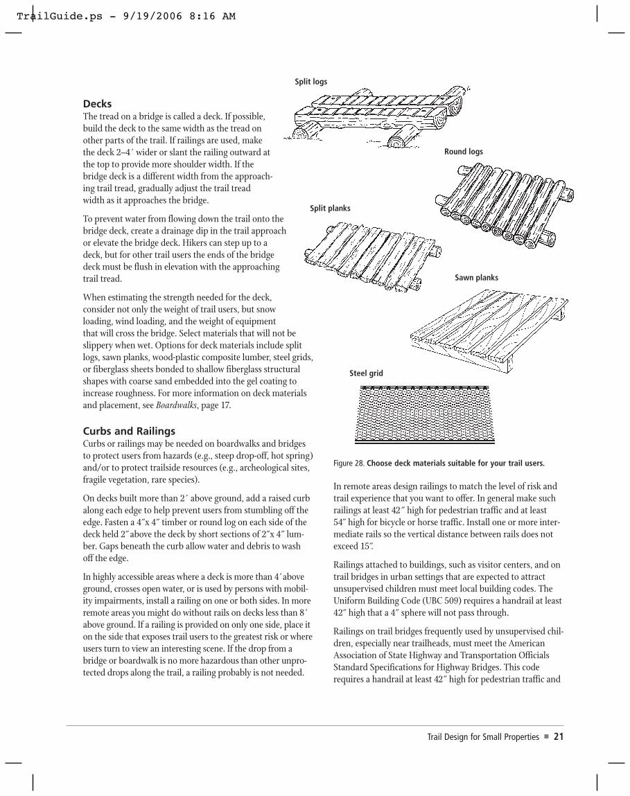
DecksThe tread on a bridge is called a deck. If possible,build the deck to the same width as the tread onother parts of the trail. If railings are used, makethe deck 2–4´ wider or slant the railing outward atthe top to provide more shoulder width. If thebridge deck is a different width from the approach-ing trail tread, gradually adjust the trail treadwidth as it approaches the bridge.
To prevent water from flowing down the trail onto thebridge deck, create a drainage dip in the trail approachor elevate the bridge deck. Hikers can step up to a deck, but for other trail users the ends of the bridgedeck must be flush in elevation with the approachingtrail tread.
When estimating the strength needed for the deck,consider not only the weight of trail users, but snowloading, wind loading, and the weight of equipmentthat will cross the bridge. Select materials that will not beslippery when wet. Options for deck materials include splitlogs, sawn planks, wood-plastic composite lumber, steel grids,or fiberglass sheets bonded to shallow fiberglass structuralshapes with coarse sand embedded into the gel coating toincrease roughness. For more information on deck materialsand placement, see Boardwalks, page 17.
Curbs and RailingsCurbs or railings may be needed on boardwalks and bridgesto protect users from hazards (e.g., steep drop-off, hot spring)and/or to protect trailside resources (e.g., archeological sites,fragile vegetation, rare species).
On decks built more than 2´ above ground, add a raised curbalong each edge to help prevent users from stumbling off theedge. Fasten a 4˝x 4˝ timber or round log on each side of thedeck held 2˝above the deck by short sections of 2˝x 4˝ lum-ber. Gaps beneath the curb allow water and debris to wash off the edge.
In highly accessible areas where a deck is more than 4´aboveground, crosses open water, or is used by persons with mobil-ity impairments, install a railing on one or both sides. In moreremote areas you might do without rails on decks less than 8´above ground. If a railing is provided on only one side, place iton the side that exposes trail users to the greatest risk or whereusers turn to view an interesting scene. If the drop from abridge or boardwalk is no more hazardous than other unpro-tected drops along the trail, a railing probably is not needed.
In remote areas design railings to match the level of risk andtrail experience that you want to offer. In general make suchrailings at least 42˝ high for pedestrian traffic and at least 54˝ high for bicycle or horse traffic. Install one or more inter-mediate rails so the vertical distance between rails does notexceed 15 .̋
Railings attached to buildings, such as visitor centers, and ontrail bridges in urban settings that are expected to attractunsupervised children must meet local building codes. TheUniform Building Code (UBC 509) requires a handrail at least42˝ high that a 4˝ sphere will not pass through.
Railings on trail bridges frequently used by unsupervised chil-dren, especially near trailheads, must meet the AmericanAssociation of State Highway and Transportation OfficialsStandard Specifications for Highway Bridges. This coderequires a handrail at least 42˝ high for pedestrian traffic and
Trail Design for Small Properties � 21
Split logs
Round logs
Split planks
Sawn planks
Steel grid
Figure 28. Choose deck materials suitable for your trail users.
TrailGuide.ps - 9/19/2006 8:16 AM

at least 54˝ high for bicycle or horse traffic. A 6˝ sphere mustnot pass through the railing in the bottom 27˝ and an 8˝sphere must not pass through the area higher than 27 .̋
On a wheelchair accessible trail where the grade is steeperthan 5%, place a rail 30–34˝ above the deck so that a personin a wheelchair can grasp it to pull their wheelchair along orrest without rolling downhill and place a second rail 42˝above the deck.
Bridges for off-highway vehicles and snowmobiles must havereflective hazard markers visible above the snow level at eachend of the bridge.
The strongest railings have vertical support posts that areanchored into the ground and fastened to the girders orstringers before extending up to the top railing. Somewhatless sturdy, but still strong, railings can be fastened to the girders or supported by outriggers.
Cut vertical support posts lower than the top railing toencourage use of the railing.
Materials for BridgesSelect bridge construction materials for durability, strength,esthetics, economics, and environmental acceptability.
� Select wood that is naturally decay resistant or is treatedwith environmentally safe chemicals. On portions of trailbridges or boardwalks that trail users touch frequently,such as railings, use wood treated with waterborne chemi-cals or light solvent oilborne chemicals. Wood without achemical preservative may last 2–12 years depending onits natural decay resistance, though some tropical woodsresist decay for over 50 years.
� Use steel that is painted or galvanized, unless it is a corrosion-resistant weathering steel. Do not use uncoatedweathering steel in coastal areas or in areas with high rainfall, high humidity, or persistent fog.
� Concrete should have an air entrainment of 4–6% and aminimum design compressive strength of 3,000 poundsper square inch. Concrete can be texturized, colored,stained, or painted to better match esthetic values.
� Fiberglass should have a waterproof, colored surface treatment to protect it from ultraviolet radiation.
� Use screws and bolts, not nails. Use non-corrosive fasten-ers that are hot-dipped galvanized, anodized plated, orstainless steel.
22
Deck
Curb
Girder
Railing fastened to posts in ground
4”x 4” curb
Railing supportedby outrigger
Raise curb with2”x 4” spacers
Screw
Notch log
2“x 4“or 4“x 4“
Railing fastened to girder
Girder
Strut
2“x 4“or 2“x 6“
Figure 29. Curbs and railings make bridge crossings safer.
TrailGuide.ps - 9/19/2006 8:16 AM
InspectionInspect bridges at least twice a year. A qualified bridge inspec-tor should evaluate bridges with long spans or complexdesigns.
Trails That Cross or Utilize RoadsCrossing RoadsAs a trail approaches a road crossing, add a tight turn, ridgesand dips in the tread, and/or narrow the clearing width toslow down users. On the final approach, the trail must be at a right (90˚) angle to the road, nearly level, and have a sightdistance adequate for trail users to see the oncoming road intime to stop. Expand the clearing width 11/2–2 times its nor-mal width or thin forest trees to provide good visibility fromthe trail toward the road.
Install warning signs if trail users include horseback riders,skiers, snowmobilers, bicyclists, motorcyclists, or othermotorized vehicle users that may not be able to stop sud-denly. Work with the road authority to determine what signsto use and where to place them. If both the trail and road arelightly used and good sight lines are present, install a Yield orStop sign on the trail at the road intersection. A Stop sign isnot required for non-wheeled and pedestrian-speed users. Iftraffic along the trail or road is moderately heavy, add a StopAhead sign on the trail. If traffic along both the trail and roadare heavy, add a Trail Crossing Ahead sign along the road towarn vehicle drivers.
If the trail may be entered from a public road, install a barrier(e.g., posts, a gate, boulders, mound of dirt) to prohibit unau-thorized entry. Install a sign visible from the road that indi-cates which trail uses are prohibited or permitted.
Ditch TrailsRegulations governing trails in public road ditches vary bystate. In Minnesota, for example, low-use trails are permittedbetween the ditch and the outside edge of state and countyroad rights-of-way. Off-highway vehicles and snowmobilesmay not use the inside slope, shoulder, and road surface ofstate and county roads. Since motorized traffic is expected totravel in the direction of travel, ditch trails are one-way in thedirection of traffic. Ditch trails are needed on both sides of ahighway to permit two-way traffic. However, a bi-directional,non-motorized trail can be provided on only one side of ahighway. Along designated ditch trails, utility poles, guywires, and other trailside obstacles must be marked with ahazard marker. For safety purposes, ditch trails that are within10–20´ of the road edge should be separated from the road bya different elevation, fence, or guard rail. Separation is more
critical where the road curves. All ditch trail design and con-struction is subject to approval by the local road authority.
Modifying Logging RoadsIf a logging skid trail or haul road will be used both for log-ging and recreational use, design it to accommodate loggingequipment. If the skid trail or road will not be used for 10years for logging purposes, then design it more like a recre-ational trail. When the time comes to use it for logging, maketemporary modifications, e.g., harden the tread, install tem-porary stream crossing devices for heavy equipment, expandthe clearing width, and install more durable culverts or otherdrainage devices.
Converting Railroad GradesBallast stones make a poor tread. The stones are uniform insize and provide fast water drainage but the surface is roughand the stones are subject to displacement. A thin layer ofballast stones makes a good base on which to place a morecompacted surface of soil or small gravel. If the railroad bed is too narrow, remove some fill to achieve a wider bed. If landownership permits it, divert the trail off the railroad bed fromtime to time to relieve boredom from long, straight sight-lines. Save bridges, but modify decks and railings to create a tread surface and width suitable for trail users.
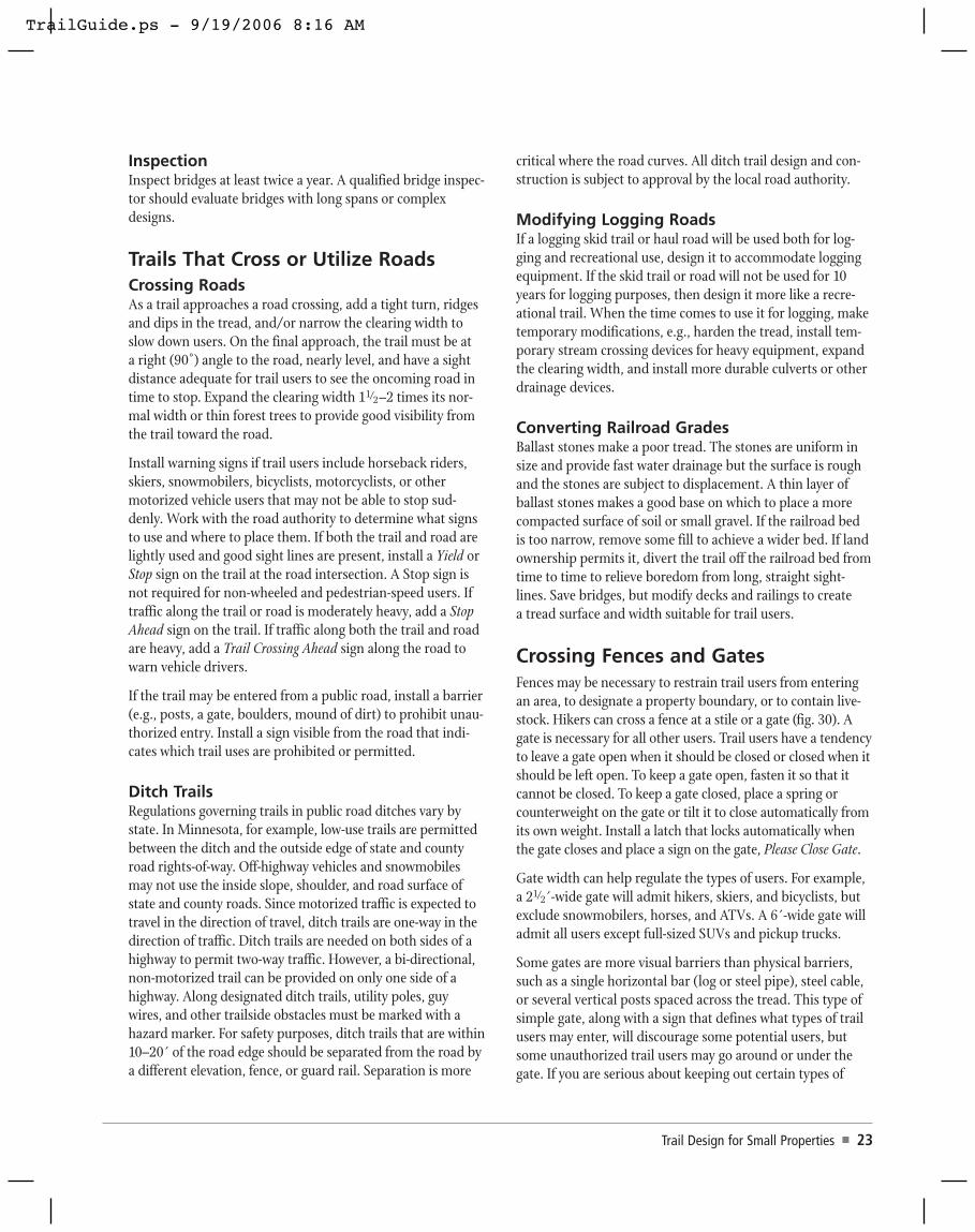
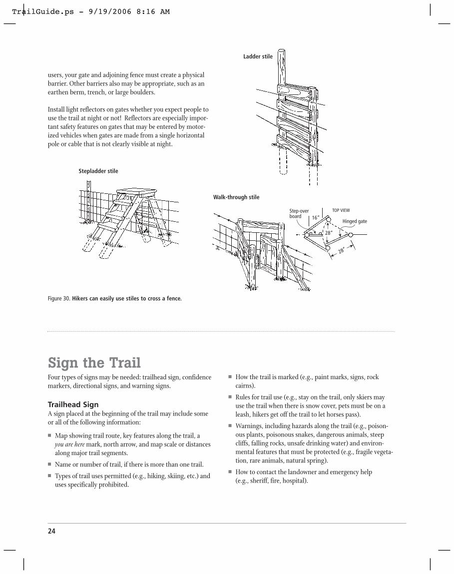
Crossing Fences and GatesFences may be necessary to restrain trail users from enteringan area, to designate a property boundary, or to contain live-stock. Hikers can cross a fence at a stile or a gate (fig. 30). Agate is necessary for all other users. Trail users have a tendencyto leave a gate open when it should be closed or closed when itshould be left open. To keep a gate open, fasten it so that itcannot be closed. To keep a gate closed, place a spring orcounterweight on the gate or tilt it to close automatically fromits own weight. Install a latch that locks automatically whenthe gate closes and place a sign on the gate, Please Close Gate.
Gate width can help regulate the types of users. For example,a 21/2´-wide gate will admit hikers, skiers, and bicyclists, butexclude snowmobilers, horses, and ATVs. A 6´-wide gate willadmit all users except full-sized SUVs and pickup trucks.
Some gates are more visual barriers than physical barriers,such as a single horizontal bar (log or steel pipe), steel cable,or several vertical posts spaced across the tread. This type ofsimple gate, along with a sign that defines what types of trailusers may enter, will discourage some potential users, butsome unauthorized trail users may go around or under thegate. If you are serious about keeping out certain types of
Trail Design for Small Properties � 23
TrailGuide.ps - 9/19/2006 8:16 AM
24
users, your gate and adjoining fence must create a physicalbarrier. Other barriers also may be appropriate, such as anearthen berm, trench, or large boulders.
Install light reflectors on gates whether you expect people touse the trail at night or not! Reflectors are especially impor-tant safety features on gates that may be entered by motor-ized vehicles when gates are made from a single horizontalpole or cable that is not clearly visible at night.
Sign the TrailFour types of signs may be needed: trailhead sign, confidencemarkers, directional signs, and warning signs.
Trailhead SignA sign placed at the beginning of the trail may include someor all of the following information:
� Map showing trail route, key features along the trail, a you are here mark, north arrow, and map scale or distancesalong major trail segments.
� Name or number of trail, if there is more than one trail.� Types of trail uses permitted (e.g., hiking, skiing, etc.) and
uses specifically prohibited.
� How the trail is marked (e.g., paint marks, signs, rockcairns).
� Rules for trail use (e.g., stay on the trail, only skiers mayuse the trail when there is snow cover, pets must be on aleash, hikers get off the trail to let horses pass).
� Warnings, including hazards along the trail (e.g., poison-ous plants, poisonous snakes, dangerous animals, steepcliffs, falling rocks, unsafe drinking water) and environ-mental features that must be protected (e.g., fragile vegeta-tion, rare animals, natural spring).
� How to contact the landowner and emergency help (e.g., sheriff, fire, hospital).
Stepladder stile
Ladder stile
Walk-through stile
TOP VIEWStep-overboard 16”
28”
28”
Hinged gate
Figure 30. Hikers can easily use stiles to cross a fence.
TrailGuide.ps - 9/19/2006 8:16 AM

Trail Design for Small Properties � 25
Post trailhead information on a large rectangular board, sized to include all relevant information. To protect signsfrom weather, build a small roof over the sign board and/orenclose signs in a shallow box with a window.
Lay out the trailhead sign in components that can be changedwithout remaking the entire sign. Print signs in fade-resistantink. (Photographs and some inks fade when exposed to sun-light.) Make letters at least 1˝ for headers and 1/4˝ for bodytext.
Figure 31. A trailhead sign provides essential informationabout the trail.
Confidence MarkersConfidence markers placed strategically along the trail reas-sure users that they are on the trail. Place them at least every1/4 mile in open country and much closer where the trail couldbe lost, e.g., at significant turns, where the trail crosses roadsor other trails, or where the tread is indistinct from the sur-rounding landscape.
� Paint marks on trees or rocks; use a template to create ageometric design, and change colors for different trails inthe same area.
� Use aluminum nails to fasten 4–6˝ steel, aluminum, orplastic diamonds to a tree, or preferably a post, so they arevisible in both directions along the trail.
� Inscribe a board or order pre-fabricated markers with anemblem, trail number, or name routed, painted, or burnedinto it.
� Pile rocks to form a cairn. Such markers are easilydestroyed by weather and vandals.
Painted mark
Metal or plastic marker
Emblem
Rock cairn
Lean rocks toward centerfor stability
Smaller rock pile indicatestravel direction at
sharp turn
Figure 32. Confidence markers help users stay on the trail.
TrailGuide.ps - 9/19/2006 8:16 AM

26
Directional SignsA sign with an arrow may be needed in aparking lot to direct trail users to the trail-head or at a sharp bend, fork, or trail cross-ing. At trail intersections, place a sign thatprovides information about where each trailleads and how far away the next significantfeature can be found. Rounded posts providethe most flexibility in positioning directionalsigns to point in the correct direction. Fastena crossbar beneath the soil to prevent vandalsfrom twisting the post.
Warning SignsThe trailhead sign should alert trail users about hazards along the trail or environmental resources thatrequire protection. Along moderately to heavily used trailsplace warning signs where trail users actually encounter haz-ardous situations or fragile environmental resources. A goodwarning sign will tell trail users what to do or not do, why,and what the consequences are. Be friendly, but persuasive.Consider using humor through your words or drawings.Drawings are as good as words if their meaning is clear.
The following are poor warning signs because they give noreason for the required action:
� “Stay Out!”� “Keep Off ”
Here are better warning signs:
� Be polite, give a reason: “Please stay on the trail. Protectthe fragile tundra!”
� More forceful: “Stay behind the fence, dangerous water,strong currents!”
It may help to give a warning and explain theconsequences:
� “$100 fine for walking on cryptobioticsoil!”
Trail users appreciate humor and still get themessage:
� “Please stay on the trail so you don’t dis-turb the rattlesnakes.” (The real purpose isto keep people from trampling the desertvegetation.)
� “Please stay on the trail so you don’t tram-ple the poison ivy.” (This may be the rea-son or it may be a way to keep trail usersfrom short-cutting a switchback.)
You also can provide a mixture of signs along a trail, somethat are polite and others that are more forceful:
� “Please stay on the trail to protect fragile wetland plants.”� “Walking on the trail is free. Walking on wetland vegeta-
tion costs $100.”
Install Facilities The most popular facilities and structures that support trailusers include: access road, parking lot, toilet, drinking water,picnic area, campground, bearproof food storage, trash con-tainer, and box of trail maps.
Undergroundbrace
DANGER
STEEPDROP-OFF
STAY ONTRAIL
POISON IVY...THREEREASONSTO
STAY ON TRAIL
Easy Moderate Difficult
Figure 33. Directional signs.
Figure 34. Warning signs help protect users and the environment.
TrailGuide.ps - 9/19/2006 8:16 AM

Removing Small Trees, Shrubs, and Limbs from Large Trees
Lopping Shears. Most lopping shearswith scissor or anvil heads cut stems upto 1˝ diameter; some models cut 3˝stems. Overall length is 26–35.̋ Longerhandles offer a greater reach and cutlarger stems more easily. Ratchet headsoffer powerful cutting with short handles.
Bow Saw. Bow saws vary in length.A 24–30˝ blade will cut 6˝ diameterwood. It cuts horizontal logs moreefficiently than standing trees. Somemodels fold for easy carrying.
Pruning Saw. A pruning saw’s curvedblade cuts on the pull stroke. Modelswith 6–10˝ blades and folding handlescan be carried in your pocket andcut limbs up to 3 .̋ Models 14–21˝long with fixed handles cut limbs upto 6 .̋
Pole Saw. A pole saw has a 14–17˝ curved blade attached to a4´ or longer handle. Use it to prune high limbs. An additionallimb hook is useful for pulling down cut limbs that get hung upin a tree. Some models have a scissor- or anvil-type pruninghead in addition to a saw.
Pole Pruner. A pole pruner with a scissoror anvil pruning head attached to a10–12´ long pole (often breaks down intwo pieces for easier carrying) cuts highlimbs up to 11/4˝ diameter. Use a polepruner to cut flexible limbs, but use a polesaw to cleanly cut limbs close to the maintree stem.
Cutting Large Trees
One-person Crosscut Saw. A one-person saw, from 3–4 1/2´in length, will fell trees or cutlogs from 6–16+˝ diameter.
Two-person Crosscut Saw.Use a two-person crosscutsaw to fell trees or cuts logsfrom 6–16+˝ diameter.
Chain Saw. A chain saw with a16–24˝ bar cuts most trees and logs.Carry extra bar oil, fuel, and chainfile. Wear a hardhat with face shield,ear muffs, long-sleeved shirt, gloves,tear resistant pants or chaps, andsturdy boots.
Pry Bar. Use a tempered steel pry bar approxi-mately 1˝ in diameter and 4–6´ long to movelogs and boulders. Or cut a tree about 4˝diameter and 10´ long for prying.
Plastic Wedge. When fellinga tree place plastic wedge(s)in the back cut to prevent thetree from leaning back andpinching the saw blade.
Removing Stumps and Boulders
Shovel. Select a shovel with a long handle, wideblade, and pointed but curved tip. Never use a wooden-handled shovel as a pry bar.
Pick Mattock. A pickmattock has a woodenhandle about 3´ long anda steel head with a 4˝wide strong hoe on oneside and a long spike onthe other side. Use it todig up stumps, rocks, andcompacted soil.
Cutter Mattock. A cutter mattock has a wooden handle about3´ long and a steel head with a 4˝ wide strong hoe on one sideand a long narrow (dull) ax on the other side. Use it to dig upstumps, rocks, and compacted soil and cut tree roots.
Trail Design for Small Properties � 27
Appendix A:
Tools for Trail Building
One-person crosscut saw
Two-person crosscut saw
Chain saw
Wedge
Pry bars
Lopping shears
Bow saw
Pruning saw
Foldingpruning saw
Pole pruner
Shovel
Pickmattock
Cuttermattock
TrailGuide.ps - 9/19/2006 8:16 AM

28
Pulaski. A Pulaski has awooden handle about 3´ longand a steel head with an axon one side and a lightweightmattock head (narrow hoe)on the other side. Use it todig up tree stumps and cutroots. A mattock is a more powerful tool for digging treestumps and rocks, but weighs much more than a Pulaski.
Ax. Look for a long handled ax to cut tree roots, split wood, orcut a felling notch into a large tree. When felling trees or cuttinglogs, use a saw for greater safety and efficiency. A single-bladedax with a hammer head on one side can be used to pound stakesand wedges, but a sledge hammer is safer. A double-bladed axallows you to change blades when one becomes dull.
Steel Wedge. Use a steel wedge with asledge hammer to split wood.
Rock Chisel. Split or break rocks using an8–12˝ long chisel with a broad chisel tip anda 3–5 lb. hammer.
Feather Wedges. Use a ham-mer to drive this set of three wedges into a widecrack to split a boulder. These wedges will notbecome stuck in a boulder as will a single steelwedge or rock chisel
Sledge Hammer. Use sledge hammers in variousweights to pound rock chisels, wood chisels, andfeather wedges.
Rock Sling. A rock sling isshaped like a litter. Two to fourpeople use it to carry heavyrocks. Its two poles may be steelpipe or wooden poles about 6́long. The sling, fashioned fromchain or strong rope, should sagclose to the ground when a rockis rolled into the center.
Rock Bag. Use this canvas bag with loophandles to carry rocks, soil, or duff.
Winch. A ratchet winch gives a 2:1mechanical advantage; a Griphoist®offers a 30:1 advantage to move bouldersand tree stumps.
Power Drill. A gasoline powered drill (jack hammer or rockdrill) with a chisel tip breaks up large boulders or bores holesinto rock for inserting explosives.
Explosives. Explosives may be necessary to uproot stumps orbreak large boulders. You need a license to purchase and useexplosives. A Boulder Buster™ is an alternative device thatrequires minimal certification and training, but breaks boul-ders larger than 6´ diameter. It is a firing mechanism attachedto a short pipe that fits into a rock crevice or hole, a steel platethat covers the hole, and an explosive charge about the sizeand shape of a shotgun shell.
Bulldozer. Use a small bulldozer with a roll bar and steel cageto clear rocks and trees and to excavate and level the tread. Touproot a large tree, cut off the stem leaving a 4´ high stump forthe bulldozer blade to push against. Use the blade to undercutroots on each side of a big stump before lifting it.
Mini-excavator. Size varies, butthe smallest mini-excavator hascaterpillar treads that spanonly 41/2 ,́ a cab for the opera-tor, and a mechanical arm witha bucket at the end. Use it toexcavate soil, rocks, and treestumps. On a steep slope it canexcavate soil to form a flat trailbed ahead of its treads.
Moving Soil, Duff, and Fill Material
Shovel. Select a shovel with a long handle, wide blade, andpointed but curved tip.
McLeod Fire Tool. A McLeodfire tool has a 6´ handle andsteel head with a 10˝wide hoeon one side and a heavy-dutyrake on the other side. Use it toclear small rocks, twigs, andbranches and to loosen soil tosmooth a tread.
Duff Blanket. Rake or shovel duff from the trail bed onto asheet of canvas or other heavy fabric, draw the four cornerstogether, then carry the lightweight duff away and dump it.
Bucket. Use 5-gallon plastic buckets with wire handles to haulfill material by hand.
McLeod fire tool
Rock bag
Mini-excavator
Rock slingSteel chain
Featherwedges
Rockchisel
Pulaski
TrailGuide.ps - 9/19/2006 8:16 AM

Trail Design for Small Properties � 29
Copyright © 2006, Regents of the University of Minnesota. All rights reserved.Send copyright permission inquiries to: Copyright Coordinator, University ofMinnesota Extension Service, 405 Coffey Hall, 1420 Eckles Avenue, St. Paul, MN55108-6068. E-mail to [email protected] or fax to: (612) 625-3967.
The information given in this publication is for educational purposes only.Reference to commercial products or trade names is made with theunderstanding that no discrimination is intended and no endorsement by theUniversity of Minnesota Extension Service is implied. Griphoist is a registeredtrademark and Boulder Buster is a trademark of their respective holders.
Need More Copies?Additional copies of this item can be ordered from the Extension Store athttp://shop.extension.umn.edu/; or place credit card orders at (800) 876-8636;or e-mail questions to: [email protected].
Alternative Formats AvailableIn accordance with the Americans with Disabilities Act, this material is availablein alternative formats upon request. Please contact your University of MinnesotaExtension Service office or the Distribution Center at (800) 876-8636.
Equal Opportunity EmployerThe University of Minnesota Extension Service is committed to the policy that allpersons shall have equal access to its programs, facilities, and employmentwithout regard to race, color, creed, religion, national origin, sex, age, maritalstatus, disability, public assistance status, veteran status, or sexual orientation.
Fill Boxes and Bags forHorses/Mules. In the back-country, mules and horses cancarry fill material in woodenboxes or heavy fabric bagsattached to each side of a load-ing frame saddle.
Wagon. Use a small wagon, especially one with a dump bed, tomove fill material and supplies. Pull it with an ATV or otherappropriate vehicle.
Safety Equipment
Hard Hat. Wear a hard hat when felling trees, cutting branchesover your head, or whenever there is a possibility of being hit byflying or falling debris. When operating a chainsaw, attach a faceshield to the hard hat.
Safety Goggles/Glasses. Wear safety goggles or glasses for alltrail clearing work, especially when working in a forest or brush-land or when cutting or chopping wood and breaking rocks.
Ear Muffs. Ear muffs for sound protection are essential whenoperating or working near noisy equipment.
Long-sleeved Shirt and Pants. They are nearly always appropri-ate to wear for protection from minor scrapes, cuts, punctures,irritating plants, biting insects, and thorns, or when operatingpower tools.
Tear-resistant Pants or Chaps. Wear these when operating achain saw or working in thorny brush.
Gloves. Wear gloves to protect your hands from blisters, cuts,and scratches, and when operating a chain saw.
Boots. Sturdy boots provide ankle support and protection fromsaw blades, thorns, sharp rocks, and other hazards.
Tool Storage and Maintenance
Storage. Make rectangular wooden boxes to haul long-handledshovels, pry bars, axes, Pulaskis, McLeod tools, etc. Carry smalltools in plastic buckets and boxes.
Maintenance. Clean tools to remove soil and rust. Use wirebrushes, steel wool, scrub brushes, and water as needed.Thoroughly dry tools, coat steel surfaces with oil to resist rust,sharpen cutting tools, and hang them for long-term storage.
Fill bag forpack animals
TrailGuide.ps - 9/19/2006 8:16 AM