Embed Size (px)
Citation preview
LOUISIANA DEPARTMENT OF TRANSPORTATION AND
DEVELOPMENT
TRAFFIC SIGNAL DESIGN MANUAL
PREPARED BY
UNDER PROJECT NO. 701-65-0278 NOVEMBER 1, 2002
NEEL-SCHAFFER, INC.
1
PURPOSE OF MANUAL
The purpose of this manual is to set forth standardized procedures to aid District Traffic Operations Engineers and Consultant Engineers in design of traffic signal installations and to apply the Department policies in doing so. It is also to serve as a guideline in the preparation of traffic signal plans and traffic signal inventory forms (TSI). This manual does not replace the Manual on Uniform Traffic Devices (MUTCD), but is intended as a supplement to it.
2
LOUISIANA DEPARTMENT OF TRANSPORTATION AND DEVELOPMENT TRAFFIC SIGNAL DESIGN MANUAL
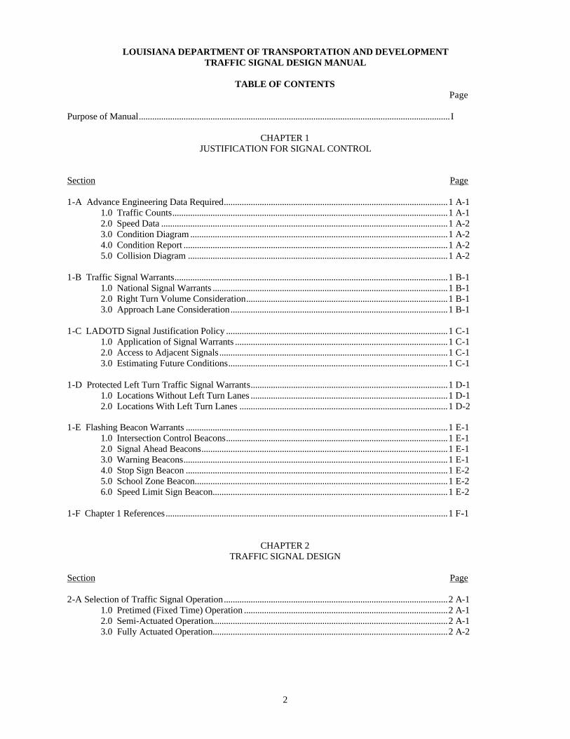
TABLE OF CONTENTS
Page
Purpose of Manual...........................................................................................................................................I
CHAPTER 1 JUSTIFICATION FOR SIGNAL CONTROL
Section Page 1-A Advance Engineering Data Required....................................................................................................1 A-1
1.0 Traffic Counts...........................................................................................................................1 A-1 2.0 Speed Data ................................................................................................................................1 A-2 3.0 Condition Diagram ...................................................................................................................1 A-2 4.0 Condition Report ......................................................................................................................1 A-2 5.0 Collision Diagram ....................................................................................................................1 A-2
1-B Traffic Signal Warrants..........................................................................................................................1 B-1
1.0 National Signal Warrants .........................................................................................................1 B-1 2.0 Right Turn Volume Consideration..........................................................................................1 B-1 3.0 Approach Lane Consideration.................................................................................................1 B-1
1-C LADOTD Signal Justification Policy ...................................................................................................1 C-1
1.0 Application of Signal Warrants ...............................................................................................1 C-1 2.0 Access to Adjacent Signals......................................................................................................1 C-1 3.0 Estimating Future Conditions..................................................................................................1 C-1
1-D Protected Left Turn Traffic Signal Warrants........................................................................................1 D-1
1.0 Locations Without Left Turn Lanes ........................................................................................1 D-1 2.0 Locations With Left Turn Lanes .............................................................................................1 D-2
1-E Flashing Beacon Warrants .....................................................................................................................1 E-1
1.0 Intersection Control Beacons...................................................................................................1 E-1 2.0 Signal Ahead Beacons..............................................................................................................1 E-1 3.0 Warning Beacons......................................................................................................................1 E-1 4.0 Stop Sign Beacon .....................................................................................................................1 E-2 5.0 School Zone Beacon.................................................................................................................1 E-2 6.0 Speed Limit Sign Beacon.........................................................................................................1 E-2
1-F Chapter 1 References..............................................................................................................................1 F-1
CHAPTER 2 TRAFFIC SIGNAL DESIGN
Section Page 2-A Selection of Traffic Signal Operation....................................................................................................2 A-1
1.0 Pretimed (Fixed Time) Operation ...........................................................................................2 A-1 2.0 Semi-Actuated Operation.........................................................................................................2 A-1 3.0 Fully Actuated Operation.........................................................................................................2 A-2
3
TABLE OF CONTENTS (CONTINUED)
Section Page 2-B Signal Phasing .........................................................................................................................................2 B-1
1.0 General ......................................................................................................................................2 B-1 2.0 Selection of Left Turn Phasing ................................................................................................2 B-1 3.0 LA DOTD Phase Assignments................................................................................................2 B-6
2-C Vehicle Detectors ....................................................................................................................................2 C-1
1.0 General ......................................................................................................................................2 C-1 2.0 Inductive Loop..........................................................................................................................2 C-1 3.0 Microloop..................................................................................................................................2 C-3 4.0 Microwave ................................................................................................................................2 C-3
2-D Signal Timing ..........................................................................................................................................2 D-1
1.0 Cycle Length.............................................................................................................................2 D-1 2.0 Pretimed (Fixed Time) Controller Timing..............................................................................2 D-3 3.0 Actuated Timing Parameters (For stop line detectors) ..........................................................2 D-7 4.0 Volume Density Timing Parameters (For advance detectors)...............................................2 D-9 5.0 Signal Timing Plans .................................................................................................................2 D-14
2-E Signal Interconnect/Coordination...........................................................................................................2 E-1
1.0 Warrant......................................................................................................................................2 E-1 2.0 Offset/Bandwidth Calculation Methods..................................................................................2 E-1 3.0 Methods of Coordination.........................................................................................................2 E-1 4.0 Installation.................................................................................................................................2 E-1
2-F Railroad Pre-emption...............................................................................................................................2 F-1
1.0 Warrant......................................................................................................................................2 F-1 2.0 Field Observation Method .......................................................................................................2 F-1 3.0 Queue Length Calculations......................................................................................................2 F-1 4.0 Grade Crossing Location .........................................................................................................2 F-3 5.0 Pre-emption Sequence..............................................................................................................2 F-3 6.0 Railroad Preemption Warning Timing....................................................................................2 F-3 7.0 Blank Out Signs........................................................................................................................2 F-7 8.0 Turn Arrows..............................................................................................................................2 F-7 9.0 Field Observation Procedure ...................................................................................................2 F-7
2-G Emergency Vehicle Pre-emption ...........................................................................................................2 G-1
1.0 Justification...............................................................................................................................2 G-1 2.0 System components for emergency vehicle preemption........................................................2 G-1 3.0 Detector Placement...................................................................................................................2 G-1
2-H Pedestrian Signal Phase ..........................................................................................................................2 H-1
1.0 Warrants ....................................................................................................................................2 H-1 2.0 Sequence ...................................................................................................................................2 H-1 3.0 Timing .......................................................................................................................................2 H-1 4.0 Pedestrian Push Buttons...........................................................................................................2 H-2
2-I Signs .........................................................................................................................................................2 I-1
1.0 Spanwire/Mast Arm Mounted .................................................................................................2 I-1 2.0 Ground Mounted Signs ............................................................................................................2 I-3 3.0 Sign Size ...................................................................................................................................2 I-4 4.0 Internally Illuminated Signs.....................................................................................................2 I-4 5.0 LA DOTD Sign Types .............................................................................................................2 I-5
4
TABLE OF CONTENTS (CONTINUED)
Section Page 2-J Signal Heads ............................................................................................................................................2 J-1
1.0 Lens Size ...................................................................................................................................2 J-1 2.0 Housing Color...........................................................................................................................2 J-1 3.0 Back Plates................................................................................................................................2 J-1 4.0 Number of Signal Faces ...........................................................................................................2 J-1 5.0 Positioning ................................................................................................................................2 J-1 6.0 Face Arrangement ....................................................................................................................2 J-2 7.0 Left Turn Signals......................................................................................................................2 J-3 8.0 Right Turn Signals....................................................................................................................2 J-3 9.0 Pedestrian Signal Indications...................................................................................................2 J-3 10.0Visibilities and Shielding .........................................................................................................2 J-4
2-K Traffic Signal Controllers/Cabinets .......................................................................................................2 K-1
1.0 Signal Controllers.....................................................................................................................2 K-1 2.0 Controller Cabinets...................................................................................................................2 K-1
2-L Power Supply...........................................................................................................................................2 L-1
1.0 Location ....................................................................................................................................2 L-1 2.0 Quantity.....................................................................................................................................2 L-1 3.0 Street Lights..............................................................................................................................2 L-1 4.0 Conduit......................................................................................................................................2 L-1
2-M Signal Supports.......................................................................................................................................2 M-1
1.0 Strain Poles ...............................................................................................................................2 M-1 2.0 Mast Arms.................................................................................................................................2 M-3
2-N Stop Lines ................................................................................................................................................2 N-1
1.0 Type Lines ................................................................................................................................2 N-1 2.0 Line Width ................................................................................................................................2 N-1 3.0 Color..........................................................................................................................................2 N-1 4.0 Orientation................................................................................................................................2 N-1 5.0 Placement ..................................................................................................................................2 N-1 6.0 Material .....................................................................................................................................2 N-1
2-O Cross Walks.............................................................................................................................................2 O-1
1.0 Type Lines ................................................................................................................................2 O-1 2.0 Line Width ................................................................................................................................2 O-1 3.0 Color..........................................................................................................................................2 O-1 4.0 Crosswalk Width ......................................................................................................................2 O-1 5.0 Location ....................................................................................................................................2 O-1 6.0 Orientation................................................................................................................................2 O-1 7.0 Material .....................................................................................................................................2 O-1
2-P Signal Wiring ...........................................................................................................................................2 P-1
1.0 Signal Device Requirement .....................................................................................................2 P-1 2.0 Mast Arm/Spanwire Cable.......................................................................................................2 P-1 3.0 Detector/Power/Interconnect Cable ........................................................................................2 P-1 4.0 Sizing Conduit ..........................................................................................................................2 P-1 5.0 Example Problem .....................................................................................................................2 P-1
5
TABLE OF CONTENTS (CONTINUED)
Section Page 2-Q Conduit.....................................................................................................................................................2 Q-1
1.0 Material Type............................................................................................................................2 Q-1 2.0 Depth Installed (Underground)................................................................................................2 Q-1 3.0 Sizing.........................................................................................................................................2 Q-1 4.0 Boring and Jacking...................................................................................................................2 Q-1
2-R Junction Boxes.........................................................................................................................................2 R-1
1.0 Purpose......................................................................................................................................2 R-1 2.0 Type/Size/Use...........................................................................................................................2 R-1 3.0 Spacing......................................................................................................................................2 R-1
2-S Street Lighting on Signal Supports.........................................................................................................2 S-1
1.0 Justification...............................................................................................................................2 S-1 2.0 Design .......................................................................................................................................2 S-1 3.0 Funding .....................................................................................................................................2 S-1 4.0 Maintenance..............................................................................................................................2 S-1 5.0 Mounting Height ......................................................................................................................2 S-1 6.0 Orientation................................................................................................................................2 S-1 7.0 Wiring Requirements ...............................................................................................................2 S-1
2-T Flashing Operations.................................................................................................................................2 T-1
1.0 Justification...............................................................................................................................2 T-1 2.0 Methods of Initiation................................................................................................................2 T-1 3.0 Signal Display...........................................................................................................................2 T-1
2-U Estimated Quantities ...............................................................................................................................2 U-1
1.0 LA DOTD Pay Items................................................................................................................2 U-1 2.0 Special Measurement Methods................................................................................................2 U-1 3.0 Plans with Multiple Signal Locations .....................................................................................2 U-1
2-V Typical Signal Installation Layouts .......................................................................................................2 V-1 2-W Signal Turn on Procedures.....................................................................................................................2 W-1
1.0 Advance Flash Period ..............................................................................................................2 W-1 2.0 Publicity ....................................................................................................................................2 W-1 3.0 Activation..................................................................................................................................2 W-1 4.0 Technical Help..........................................................................................................................2 W-1 5.0 Signing Revisions.....................................................................................................................2 W-1 6.0 Police Assistance ......................................................................................................................2 W-1 7.0 School Crossing........................................................................................................................2 W-1 8.0 Fine Tuning...............................................................................................................................2 W-1
2-X Chapter 2 References .............................................................................................................................2 X-1
6
TABLE OF CONTENTS (CONTINUED)
CHAPTER 3 SIGNAL PLANS
Section Page 3-A General....................................................................................................................................................3 A-1
1.0 Part of Road Construction Plans..............................................................................................3 A-1 2.0 “Stand Alone” Signal Plans .....................................................................................................3 A-1
3-B Plan Sheets Required..............................................................................................................................3 B-1
1.0 Title Sheet .................................................................................................................................3 B-1 2.0 Signal General Notes Sheet .....................................................................................................3 B-2 3.0 Summary of Quantities Sheet ..................................................................................................3 B-2 4.0 Intersection Layout Sheet ........................................................................................................3 B-2 5.0 Signal Timing/Operations Sheet..............................................................................................3 B-4 6.0 Railroad Preemption Sheet (If Applicable) ............................................................................3 B-6 7.0 Signal Interconnect Layout Sheet (If Applicable)..................................................................3 B-7
CHAPTER 4 TRAFFIC SIGNAL INVENTORY (TSI) FORMS
Section Page 4-A General....................................................................................................................................................4 A-1
1.0 When Required .........................................................................................................................4 A-1 2.0 Preparation Format...................................................................................................................4 A-1 3.0 Submittal Format......................................................................................................................4 A-1
4-B Standard Forms.......................................................................................................................................4 B-1
1.0 Primary Sequence/Timing Plan Form.....................................................................................4 B-1 2.0 Supplemental Phasing & Timing Form ..................................................................................4 B-1 3.0 Intersection Diagram Form......................................................................................................4 B-1 4.0 Phase Timing Parameters Forms.............................................................................................4 B-2 5.0 Emergency Preemption Forms ................................................................................................4 B-2 6.0 Railroad Preemption Forms.....................................................................................................4 B-2 7.0 Traffic Count/Detector Form...................................................................................................4 B-2 8.0 Modification and Inspection Record Form.............................................................................4 B-2
7
LOUISIANA DEPARTMENT OF TRANSPORTATION AND DEVELOPMENT TRAFFIC SIGNAL DESIGN MANUAL
LIST OF FIGURES
Chapter 1 Justification for Signal Control Figure Subject At the End of No. Chapter/Section 1 A-1 Machine Count Format Example ....................................................................................................................................1A 1 A-2 Manual Turning Movement Count Format Example ....................................................................................................1A 1 A-3 Condition Diagram Example...........................................................................................................................................1A 1 A-4 Intersection Condition Report Example .........................................................................................................................1A 1 A-5 Collision Diagram Example ............................................................................................................................................1A
Chapter 2
Traffic Signal Design 2 B-1 Left Turn Sight Distance..................................................................................................................................................2B 2 B-2 Leading Left Turn with Protected – Permitted Operation.............................................................................................2B 2 B-3 Lagging Left Turn with Protected – Permitted Operation.............................................................................................2B 2 B-4 Lead – Lag Left Turns with Protected – Permitted Operation ......................................................................................2B 2 B-5 Simultaneous Leading Left Turns with Protected – Permitted Operation....................................................................2B 2 B-6 Split Phase Left Turns......................................................................................................................................................2B 2 B-7 LA DOTD Phase Assignments, 4 – Way Intersections (N-S Main St.) .......................................................................2B 2 B-8 LA DOTD Phase Assignments, 4 – Way Intersections (E-W Main St.) ......................................................................2B 2 B-9 LA DOTD Phase Assignments, T – Intersections, (N-S Main St./ East Approach Minor St.)...............................................................................................................................................2B 2 B-10 LA DOTD Phase Assignments, T – Intersections, (N-S Main St./ West Approach Minor St.) .............................................................................................................................................2B 2 B-11 LA DOTD Phase Assignments, T – Intersections, (E-W Main St./ South Approach Minor St.) ............................................................................................................................................2B 2 B-12 LA DOTD Phase Assignments, T – Intersections, (E-W Main St./ North Approach Minor St.) ............................................................................................................................................2B 2 C-1 Loop Detector Size...........................................................................................................................................................2C 2 C-2 Loop Detector Placement/Pattern (Minor Approach) ....................................................................................................2C 2 C-3 Loop Detector Placement/Pattern (Major/Minor Approach, Left Turn Lane)...............................................................................................................................................................2C 2 C-4 Loop Detector Placement/Pattern (Major Approach) ....................................................................................................2C 2 C-5 Loop Detector Wiring ......................................................................................................................................................2C 2 C-6 Microloop Placement/Pattern..........................................................................................................................................2C 2 C-7 Microwave Detector Placement/Pattern (Passage/Presence) ........................................................................................2C 2 C-8 Microwave Detector Placement/Pattern (Presence).......................................................................................................2C
2 D-1 Critical Lane Volume Determination Example..............................................................................................................2D 2 D-2 Actuated Phase Intervals .................................................................................................................................................2D 2 D-3 Volume Density Intervals................................................................................................................................................2D 2 D-4 Vehicle/Pedestrian Timing Relationship........................................................................................................................2D 2 D-5 Multiple Timing Plan Example.......................................................................................................................................2D
8
LIST OF FIGURES (CONTINUED) Figure Subject At the End of No. Chapter/Section 2 F-1 Typical Railroad Preemption Sequence for 2 Phase Operation.....................................................................................2F 2 F-2 Illustration of Track Clearance Distance (TCD).............................................................................................................2F 2 F-3 Railroad Preemption Worksheet, Field Observation Method........................................................................................2F 2 G-1 Typical Emergency Vehicle Preemption Sequence for 2-Phase Operation.................................................................2G 2 H-1 Pedestrian Push Button Signs..........................................................................................................................................2H 2 I-1 Typical Sign/Signal Arrangements, One Lane Approach..............................................................................................2I 2 I-2 Typical Sign/Signal Arrangements, One Lane Approach with Separate Left Turn lane ..................................................................................................................................................2I 2 I-3 Typical Sign/Signal Arrangements, One Lane Approach, with Protected/Permitted Left Turn........................................................................................................................................2I 2 I-4 Typical Sign/Signal Arrangements, One Lane Approach, with Separate Left Turn Lane, Protected/Permitted Left Turn.............................................................................................2I 2 I-5 Typical Sign/Signal Arrangements, One Lane Approach, with Separate Left Turn Lane, Protected Only Left Turn.....................................................................................................2I 2 I-6 Typical Sign/Signal Arrangements, Two Lane Approach Protected/Permitted Left Turn........................................................................................................................................2I 2 I-7 Typical Sign/Signal Arrangements, Two Lane Approach with Separate Left Turn Lane, Protected/Permitted Left Turn.............................................................................................2I 2 I-8 Typical Sign/Signal Arrangements, Two Lane Approach with Separate Left Turn Lane, Protected Only Left Turn.....................................................................................................2I 2 I-9 Typical Sign/Signal Arrangements, Two Lane Approach with Separate Left and Right Turn Lanes, Protected/Permitted Left Turn ........................................................................2I 2 I-10 Typical Sign/Signal Arrangements, Two Lane Approach with Dual Left Turn Lanes, Protected Only Left Turn........................................................................................................2I 2 I-11 Typical Sign/Signal Arrangements, Three Lane Approach with Separate Left Turn Lane, Protected Only Left Turn ...................................................................................................2I 2 I-12 Typical Sign/Signal Arrangements, T – Intersection, One Lane Approach ..............................................................2I 2 I-13 Typical Sign/Signal Arrangements, T – Intersection, Two Lane Approach .............................................................2I 2 I-14 Typical Sign/Signal Arrangements, T – Intersection, Two Lane Approach, Dual Left Turn ...............................................................................................................................................................2I 2 I-15 Typical Sign/Signal Arrangements, T – Intersection, Two Lane Approach with Separate Left Turn Lane, Right Turn Overlap.............................................................................................................2I 2 I-16 “T – Treatment” Signing...............................................................................................................................................2I 2 J-1 Horizontal Location of Signal Faces ............................................................................................................................2J 2 J-2 Maximum Mounting Height of Signal Faces ..............................................................................................................2J 2 L-1 Power Supply Within 20 Ft. of Controller...................................................................................................................2L 2 L-2 Power Supply Beyond 20 Ft. of Controller .................................................................................................................2L 2 L-3 Power Supply for Locations with Street Lights...........................................................................................................2L 2 M-1 Typical Strain Pole (Spanwire) Installations, Box Span.............................................................................................2M 2 M-2 Typical Strain Pole (Spanwire) Installations, Z – Span (with Cubed Median) ....................................................................................................................................2M 2 M-3 Typical Strain Pole (Spanwire) Installations, Z – Span (with Offset Intersection) ..............................................................................................................................2M
9
LIST OF FIGURES (CONTINUED) Figure Subject At the End of No. Chapter/Section 2 M-4 Typical Strain Pole (Spanwire) Installations, U – Span (T – Intersection)...........................................................................................................................................2M 2 M-5 DOTD Signal Pole Height Determination...................................................................................................................2M 2 M-6 Typical Mast Arm Installations, Signal Arm...............................................................................................................2M 2 M-7 Typical Mast Arm Installations, Dual Arms, (with Curbed Medium)..................................................................................................................................................2M 2 M-8 Typical Mast Arm Installations, Dual Arms, (Offset Intersections).....................................................................................................................................................2M 2 M-9 Typical Mast Arm Installations, Dual Arms, (T - Intersections) .........................................................................................................................................................2M 2 M-10 Typical Mast Arm Height ............................................................................................................................................2M 2 N-1 Stop Line Placement (Determined by Cross St. Turning Vehicles)...........................................................................2N 2 N-2 Stop Line Placement (Without Crosswalks)................................................................................................................2N 2 N-3 Stop Line Placement (With Crosswalks) .....................................................................................................................2N 2 N-4 Stop Line Placement (Parallel to Cross St.).................................................................................................................2N 2 O-1 Typical Crosswalk Markings ........................................................................................................................................2O 2 P-1 Typical Spanwire Signal Wiring ..................................................................................................................................2P 2 P-2 Typical Mast Arm Signal Wiring.................................................................................................................................2P 2 P-3 Signal Wiring Example Problem..................................................................................................................................2P 2 S-1 Street Light Location Example.....................................................................................................................................2S 2 V-1 Signal Layout, 4-Way (2 Lane Main St.) 2 Phase, Pretimed......................................................................................2V 2 V-2 Signal Layout, 4-Way (2 Lane Main St.) 2 Phase, Semi-Actuated............................................................................2V 2 V-3 Signal Layout, 4-Way (2 Lane Main St.) 2 Phase, Fully Actuated ............................................................................2V 2 V-4 Signal Layout, 4-Way (2 Lane Main St.) 2 Phase, Fully Actuated With Pedestrian Phases .................................................................................................................................................2V 2 V-5 Signal Layout, 4-Way (2 Lane Main St.) 3 Phase, Fully Actuated with Pedestrian Phases, Leading Protected/Permitted Left Turn (Main St.) .............................................................2V 2 V-6 Signal Layout, 4-Way (2 Lane Main St. with Left Turn Bays) 3 Phase, Fully Actuated with Pedestrian Phases, Simultaneous Leading Protected/Permitted Left Turns (Main St.) ..................................................................................................................2V 2 V-7 Signal Layout, 4-Way (2 Lane Main St. with Left Turn Bays) 4 Phase, Fully Actuated with Pedestrian Phases, Simultaneous Leading Protected/Permitted Left Turns (Main St.), (Side Street Split) ..................................................................................2V 2 V-8 Signal Layout, 4-Way (2 Lane Main St. with Left Turn Bays) 4 Phase, Fully Actuated with Pedestrian Phases, Simultaneous Leading Protected/Permitted Left Turn (Main St.), (Both Streets)...........................................................................................2V 2 V-9 Signal Layout, 4-Way (2 Lane Main St. with Left Turn Bays) 4 Phase, Fully Actuated with Pedestrian Phases, Lead/Lag Protected Only Left Turn (Main St.) ............................................................................................................................2V 2 V-10 Signal Layout, 4-Way (4 Lane Main St.) 2 Phase, Fully Actuated With Pedestrian Phases .................................................................................................................................................2V 2 V-11 Signal Layout, 4-Way (4 Lane Main St.) 4 Phase, Fully Actuated With Pedestrian Phases, Lead/Lag Protected/Protected Left Turns (Main St.).........................................................2V 2 V-12 Signal Layout, 4-Way (4 Lane Main St. with Left Turn Bays) 4 Phase, Fully Actuated with Pedestrian Phases, Simultaneous Leading Protected/Permitted Left Turns (Both Streets)..............................................................................................2V
10
LIST OF FIGURES (CONTINUED) Figure Subject At the End of No. Chapter/Section 2 V-13 Signal Layout, 4-Way (4 Lane Main St. with Left Turn Bays) 6 Phase, Fully Actuated with Pedestrian Phases, Lead/Lag Protected Only Left Turns (Both Streets) .....................................................................................................................................2V 2 V-14 Signal Layout, 4-Way (4 Lane Main St. with Dual Left Turn Bays) 5 Phase, Fully Actuated with Pedestrian Phases, Protected Only Left Turns (Main St.).............................................................................................................................................................2V 2 V-15 Signal Layout, 4-Way (4 Lane Main St. with Left, Right Bays) 4 Phase, Fully Actuated with Pedestrian Phases, Simultaneous Leading Protected/Permitted Left Turns (Main St.), Right Turn Overlap (Main St.) .............................................................2V 2 V-16 Signal Layout, 4-Way (4 Lane Main St. with Left, Right Bays) 4 Phase, Fully Actuated, with Pedestrian Phases, Simultaneous Leading Protected Only Left Turns (Main St.), Right Turn Overlap (Main St.) .....................................................................2V 2 V-17 Signal Layout, “T” (2 Lane Main St.) 2 Phase, Pretimed...........................................................................................2V 2 V-18 Signal Layout, “T” (2 Lane Main St.) 2 Phase, Semi-Actuated .................................................................................2V 2 V-19 Signal Layout, “T” (2 Lane Main St.) 2 Phase, Fully Actuated .................................................................................2V
2 V-20 Signal Layout, “T” (2 Lane Main St.) 2 Phase, Fully Actuated With Pedestrian Phases .................................................................................................................................................2V 2 V-21 Signal Layout, “T” (2 Lane Main St.) 3 Phase, Fully Actuated With Pedestrian Phases, Leading Protected/Permitted Left Turn (Main St.) ............................................................2V 2 V-22 Signal Layout, “T” (2 Lane Main St. with Left Turn Bays) 3 Phase, Fully Actuated with Pedestrian Phases, Leading Protected/ Permitted Left Turn (Main St.), Right Turn Overlap (Side St.) .................................................................................2V 2 V-23 Signal Layout, “T” (2 Lane Main St. with Left Turn Bays) 3 Phase, Fully Actuated with Pedestrian Phases, Leading Protected Only Left Turn (Main St.), Right Turn Overlap (Side St.) ..................................................................................................2V 2 V-24 Signal Layout, “T” (4 Lane Main St.) 3 Phase, Fully Actuated with Pedestrian Phases, Leading Protected/Permitted Left Turn (Main St.), Dual Left Turn (Side St.) ..............................................................................................................................................2V 2 V-25 Signal Layout, “T” (4 Lane Main St. with Left Turn Bays) 3 Phase, Fully Actuated with Pedestrian Phases, Leading Protected/Permitted Left Turn (Main St.), Right Turn Overlap (Side St.) ..........................................................................................................2V 2 V-26 Signal Layout, “T” (4 Lane Main St. with Left Turn Bays) 3 Phase, Fully Actuated with Pedestrian Phases, Leading Protected Only Left Turn (Main St.), Right Turn Overlap ( Side St.) ..................................................................................................................2V 2 V-27 Signal Layout, “T” (4 Lane Main St. with Left, Right Bays) 3 Phase, Fully Actuated, Leading Protected/Permitted Left Turn (Main St.) Right Turn Overlap (Both St.) ......................................................................................................................................2V 2 V-28 Signal Layout, “T” (4 Lane Main St. with Left, Right Bays) 3 Phase, Fully Actuated, Leading Protected Only Left Turn (Main St.), Right Turn Overlap (Both St.) ................................................................................................................................................2V 2 V-29 Signal Layout, “T” (4 Lane Main St. with Dual Left Turn Bay) 3 Phase, Fully Actuated, Leading Protected Only Left Turn (Main St.), Right Turn Overlap (Side St.) .................................................................................................................................................2V
11
LIST OF FIGURES (CONTINUED) Chapter 3
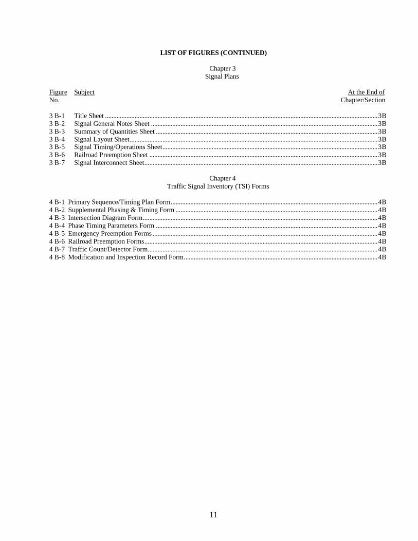
Signal Plans Figure Subject At the End of No. Chapter/Section 3 B-1 Title Sheet ......................................................................................................................................................................3B 3 B-2 Signal General Notes Sheet ..........................................................................................................................................3B 3 B-3 Summary of Quantities Sheet .......................................................................................................................................3B 3 B-4 Signal Layout Sheet.......................................................................................................................................................3B 3 B-5 Signal Timing/Operations Sheet...................................................................................................................................3B 3 B-6 Railroad Preemption Sheet ...........................................................................................................................................3B 3 B-7 Signal Interconnect Sheet..............................................................................................................................................3B
Chapter 4 Traffic Signal Inventory (TSI) Forms
4 B-1 Primary Sequence/Timing Plan Form..............................................................................................................................4B 4 B-2 Supplemental Phasing & Timing Form ...........................................................................................................................4B 4 B-3 Intersection Diagram Form...............................................................................................................................................4B 4 B-4 Phase Timing Parameters Form .......................................................................................................................................4B 4 B-5 Emergency Preemption Forms .........................................................................................................................................4B 4 B-6 Railroad Preemption Forms..............................................................................................................................................4B 4 B-7 Traffic Count/Detector Form............................................................................................................................................4B 4 B-8 Modification and Inspection Record Form......................................................................................................................4B
12
LOUISIANA DEPARTMENT OF TRANSPORTATION AND DEVELOPMENT TRAFFIC SIGNAL DESIGN MANUAL
LIST OF TABLES
Table Subject At the End of No. Chapter/Section
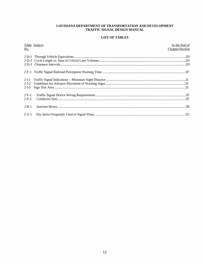
2 D-1 Through Vehicle Equivalents..........................................................................................................................................2D 2 D-2 Cycle Length vs. Sum of Critical Lane Volumes ..........................................................................................................2D 2 D-3 Clearance Intervals...........................................................................................................................................................2D 2 F-1 Traffic Signal Railroad Preemption Warning Time .......................................................................................................2F 2 I-1 Traffic Signal Indications – Minimum Sight Distance ..................................................................................................2I 2 I-2 Guidelines for Advance Placement of Warning Signs...................................................................................................2I 2 I-3 Sign Size Area ..................................................................................................................................................................2I 2 P-1 Traffic Signal Device Wiring Requirements ...............................................................................................................2P 2 P-2 Conductor Size...............................................................................................................................................................2P 2 R-1 Junction Boxes...............................................................................................................................................................2R 2 U-1 Pay Items Frequently Used in Signal Plans.................................................................................................................2U
CHAPTER 1
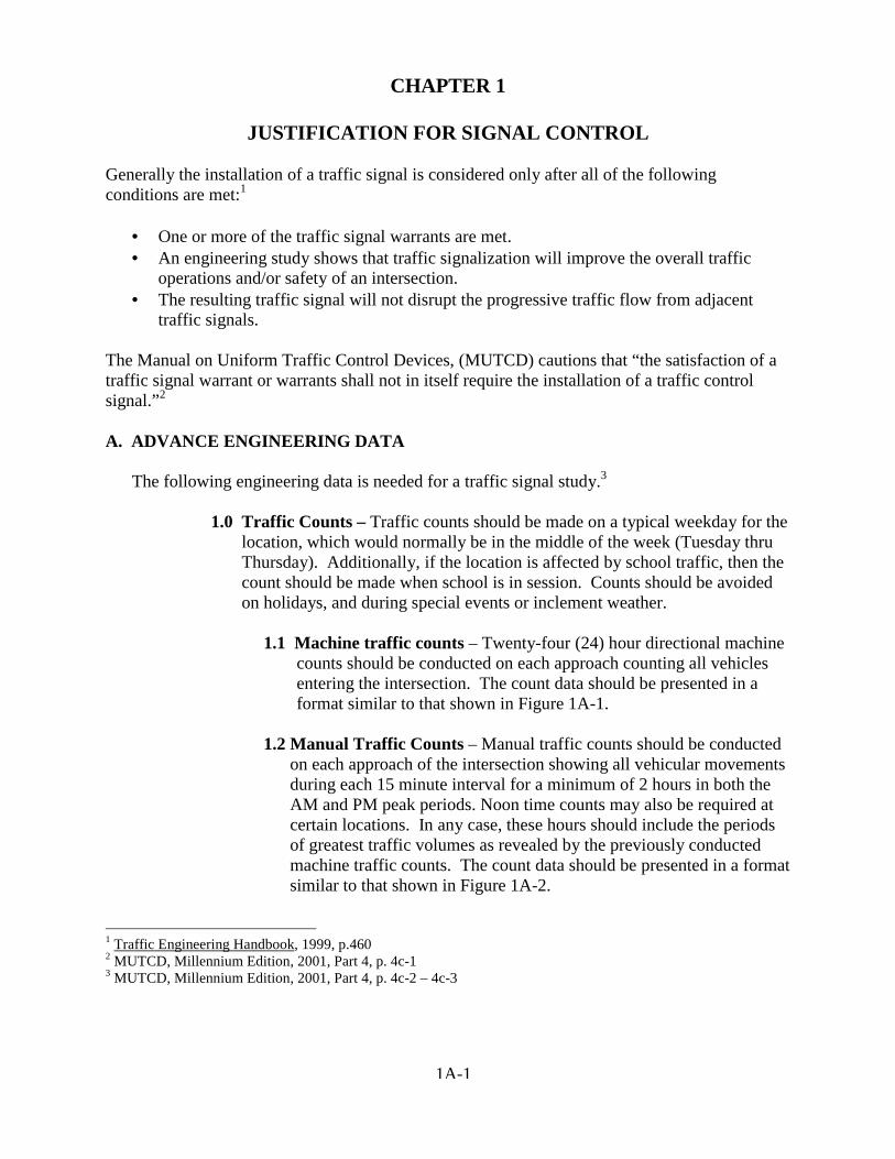
JUSTIFICATION FOR SIGNAL CONTROL Generally the installation of a traffic signal is considered only after all of the following conditions are met:1
• One or more of the traffic signal warrants are met. • An engineering study shows that traffic signalization will improve the overall traffic
operations and/or safety of an intersection. • The resulting traffic signal will not disrupt the progressive traffic flow from adjacent
traffic signals. The Manual on Uniform Traffic Control Devices, (MUTCD) cautions that “the satisfaction of a traffic signal warrant or warrants shall not in itself require the installation of a traffic control signal.”2 A. ADVANCE ENGINEERING DATA The following engineering data is needed for a traffic signal study.3
1.0 Traffic Counts – Traffic counts should be made on a typical weekday for the location, which would normally be in the middle of the week (Tuesday thru Thursday). Additionally, if the location is affected by school traffic, then the count should be made when school is in session. Counts should be avoided on holidays, and during special events or inclement weather.
1.1 Machine traffic counts – Twenty-four (24) hour directional machine
counts should be conducted on each approach counting all vehicles entering the intersection. The count data should be presented in a format similar to that shown in Figure 1A-1.
1.2 Manual Traffic Counts – Manual traffic counts should be conducted
on each approach of the intersection showing all vehicular movements during each 15 minute interval for a minimum of 2 hours in both the AM and PM peak periods. Noon time counts may also be required at certain locations. In any case, these hours should include the periods of greatest traffic volumes as revealed by the previously conducted machine traffic counts. The count data should be presented in a format similar to that shown in Figure 1A-2.
1 Traffic Engineering Handbook, 1999, p.460 2 MUTCD, Millennium Edition, 2001, Part 4, p. 4c-1 3 MUTCD, Millennium Edition, 2001, Part 4, p. 4c-2 – 4c-3
1A-1
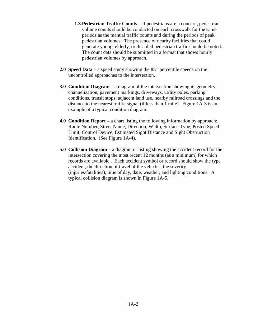
1.3 Pedestrian Traffic Counts – If pedestrians are a concern, pedestrian volume counts should be conducted on each crosswalk for the same periods as the manual traffic counts and during the periods of peak pedestrian volumes. The presence of nearby facilities that could generate young, elderly, or disabled pedestrian traffic should be noted. The count data should be submitted in a format that shows hourly pedestrian volumes by approach.
2.0 Speed Data – a speed study showing the 85th percentile speeds on the
uncontrolled approaches to the intersection.
3.0 Condition Diagram – a diagram of the intersection showing its geometry, channelization, pavement markings, driveways, utility poles, parking conditions, transit stops, adjacent land use, nearby railroad crossings and the distance to the nearest traffic signal (if less than 1 mile). Figure 1A-3 is an example of a typical condition diagram.
4.0 Condition Report – a chart listing the following information by approach:
Route Number, Street Name, Direction, Width, Surface Type, Posted Speed Limit, Control Device, Estimated Sight Distance and Sight Obstruction Identification. (See Figure 1A-4).
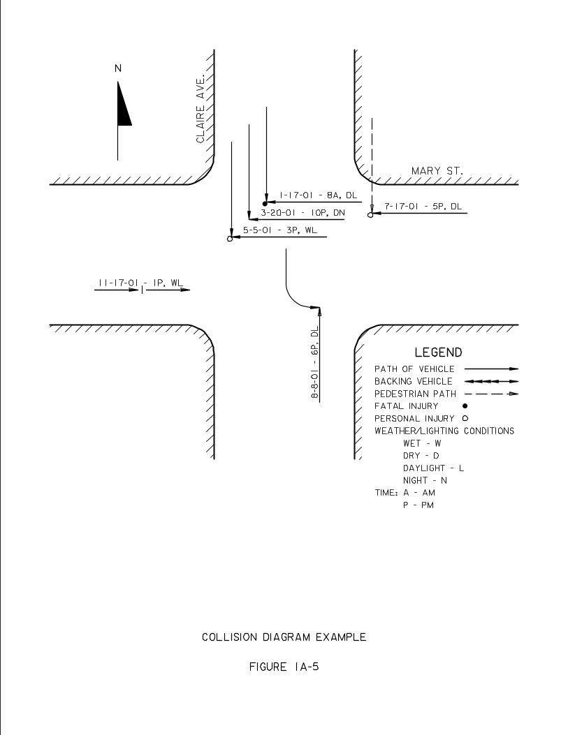
5.0 Collision Diagram – a diagram or listing showing the accident record for the
intersection covering the most recent 12 months (as a minimum) for which records are available . Each accident symbol or record should show the type accident, the direction of travel of the vehicles, the severity (injuries/fatalities), time of day, date, weather, and lighting conditions. A typical collision diagram is shown in Figure 1A-5.
1A-2
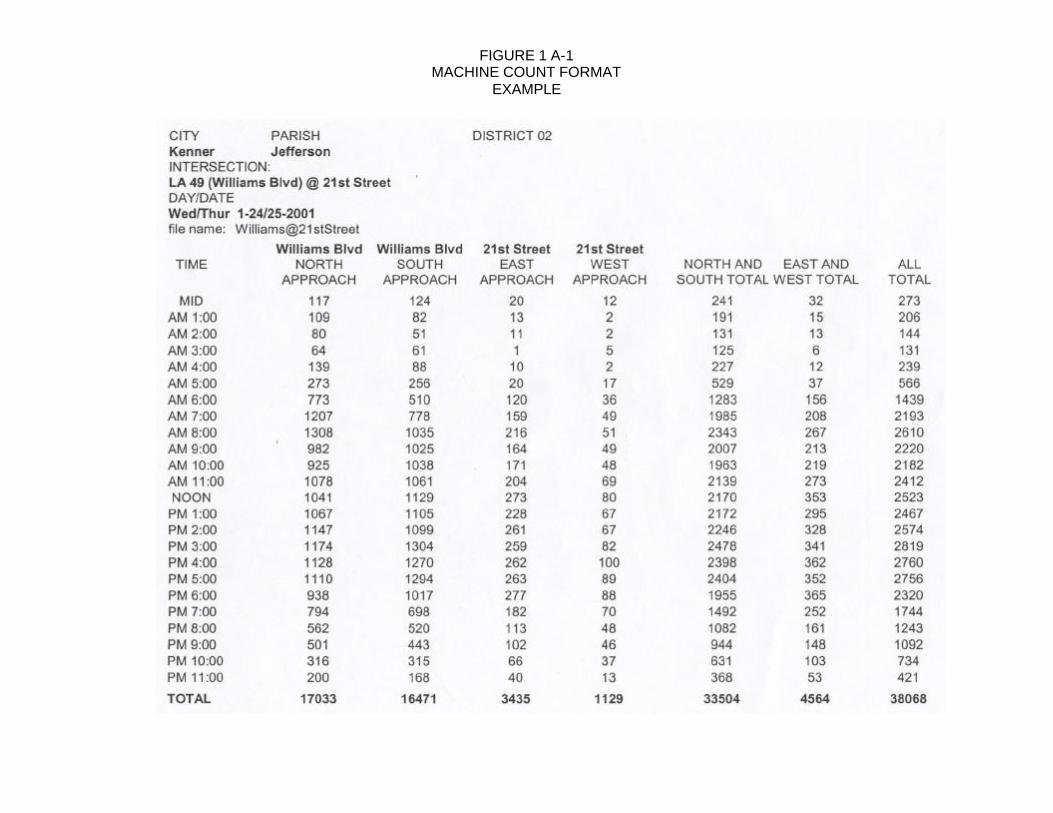
FIGURE 1 A-1 MACHINE COUNT FORMAT
EXAMPLE
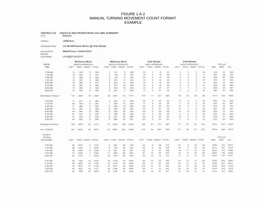
FIGURE 1 A-2 MANUAL TURNING MOVEMENT COUNT FORMAT
EXAMPLE
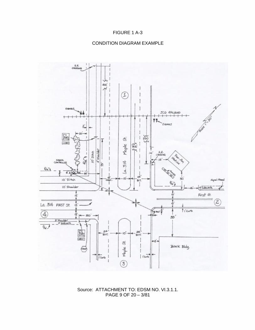
FIGURE 1 A-3
CONDITION DIAGRAM EXAMPLE
Source: ATTACHMENT TO: EDSM NO. VI.3.1.1. PAGE 9 OF 20 – 3/81
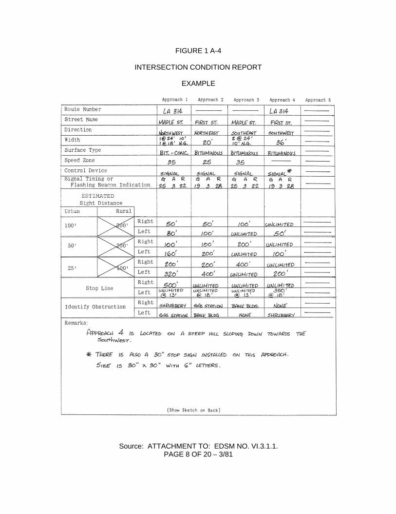
FIGURE 1 A-4
INTERSECTION CONDITION REPORT
EXAMPLE
Source: ATTACHMENT TO: EDSM NO. VI.3.1.1. PAGE 8 OF 20 – 3/81
B. TRAFFIC SIGNAL WARRANTS
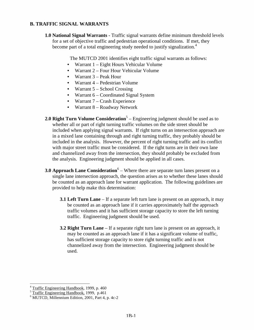
1.0 National Signal Warrants - Traffic signal warrants define minimum threshold levels for a set of objective traffic and pedestrian operational conditions. If met, they become part of a total engineering study needed to justify signalization.4
The MUTCD 2001 identifies eight traffic signal warrants as follows:
• Warrant 1 – Eight Hours Vehicular Volume • Warrant 2 – Four Hour Vehicular Volume • Warrant 3 – Peak Hour • Warrant 4 – Pedestrian Volume • Warrant 5 – School Crossing • Warrant 6 – Coordinated Signal System • Warrant 7 – Crash Experience • Warrant 8 – Roadway Network
2.0 Right Turn Volume Consideration5 – Engineering judgment should be used as to
whether all or part of right turning traffic volumes on the side street should be included when applying signal warrants. If right turns on an intersection approach are in a mixed lane containing through and right turning traffic, they probably should be included in the analysis. However, the percent of right turning traffic and its conflict with major street traffic must be considered. If the right turns are in their own lane and channelized away from the intersection, they should probably be excluded from the analysis. Engineering judgment should be applied in all cases.
3.0 Approach Lane Consideration6 – Where there are separate turn lanes present on a
single lane intersection approach, the question arises as to whether these lanes should be counted as an approach lane for warrant application. The following guidelines are provided to help make this determination:
3.1 Left Turn Lane – If a separate left turn lane is present on an approach, it may
be counted as an approach lane if it carries approximately half the approach traffic volumes and it has sufficient storage capacity to store the left turning traffic. Engineering judgment should be used.
3.2 Right Turn Lane – If a separate right turn lane is present on an approach, it
may be counted as an approach lane if it has a significant volume of traffic, has sufficient storage capacity to store right turning traffic and is not channelized away from the intersection. Engineering judgment should be used.
4 Traffic Engineering Handbook, 1999, p. 460 5 Traffic Engineering Handbook, 1999, p.461 6 MUTCD, Millennium Edition, 2001, Part 4, p. 4c-2
1B-1
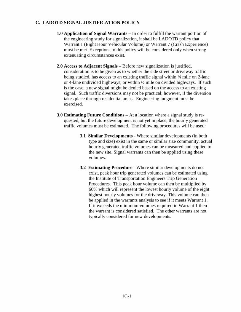
C. LADOTD SIGNAL JUSTIFICATION POLICY 1.0 Application of Signal Warrants – In order to fulfill the warrant portion of
the engineering study for signalization, it shall be LADOTD policy that Warrant 1 (Eight Hour Vehicular Volume) or Warrant 7 (Crash Experience) must be met. Exceptions to this policy will be considered only when strong extenuating circumstances exist.
2.0 Access to Adjacent Signals – Before new signalization is justified,
consideration is to be given as to whether the side street or driveway traffic being studied, has access to an existing traffic signal within ¼ mile on 2-lane or 4-lane undivided highways, or within ½ mile on divided highways. If such is the case, a new signal might be denied based on the access to an existing signal. Such traffic diversions may not be practical; however, if the diversion takes place through residential areas. Engineering judgment must be exercised.
3.0 Estimating Future Conditions – At a location where a signal study is re-
quested, but the future development is not yet in place, the hourly generated traffic volumes must be estimated. The following procedures will be used:
3.1 Similar Developments - Where similar developments (in both
type and size) exist in the same or similar size community, actual hourly generated traffic volumes can be measured and applied to the new site. Signal warrants can then be applied using these volumes.
3.2 Estimating Procedure - Where similar developments do not
exist, peak hour trip generated volumes can be estimated using the Institute of Transportation Engineers Trip Generation Procedures. This peak hour volume can then be multiplied by 60% which will represent the lowest hourly volume of the eight highest hourly volumes for the driveway. This volume can then be applied in the warrants analysis to see if it meets Warrant 1. If it exceeds the minimum volumes required in Warrant 1 then the warrant is considered satisfied. The other warrants are not typically considered for new developments.
1C-1
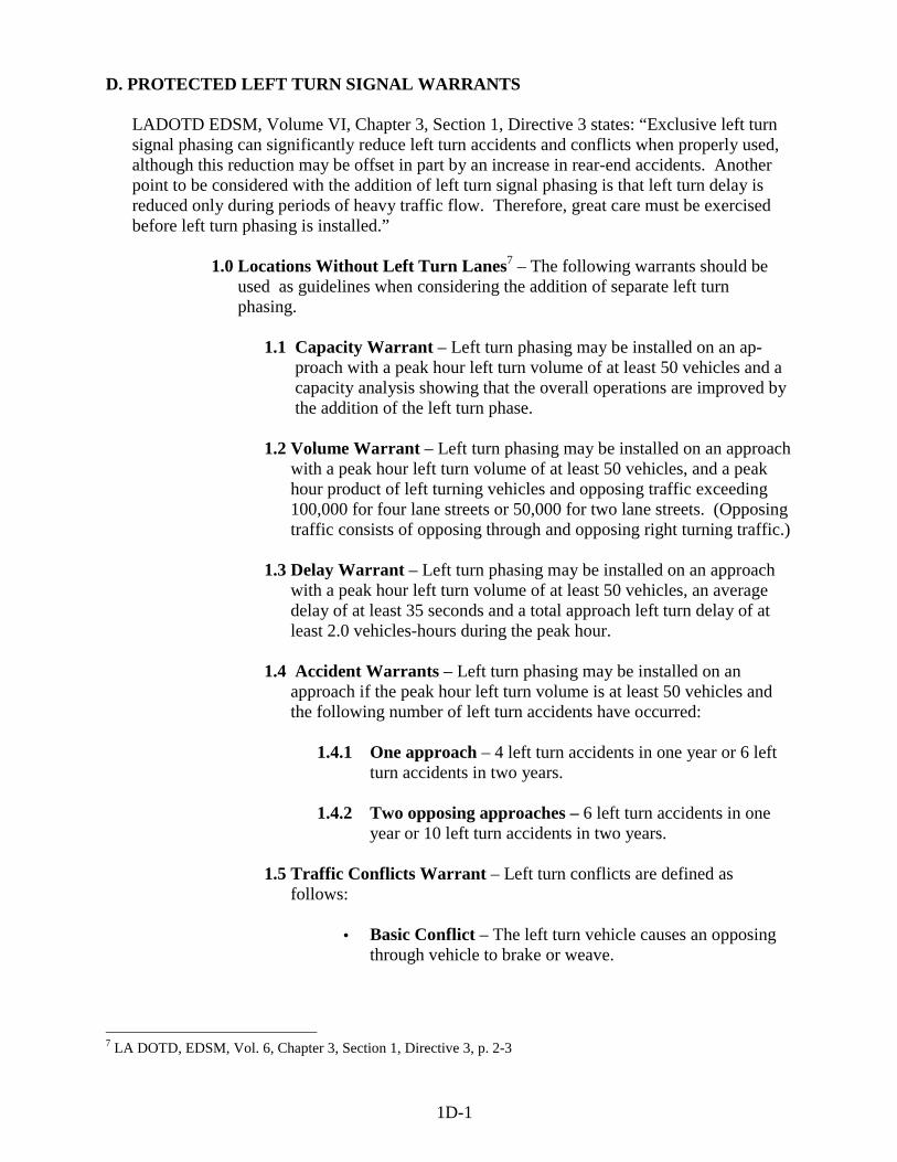
D. PROTECTED LEFT TURN SIGNAL WARRANTS LADOTD EDSM, Volume VI, Chapter 3, Section 1, Directive 3 states: “Exclusive left turn signal phasing can significantly reduce left turn accidents and conflicts when properly used, although this reduction may be offset in part by an increase in rear-end accidents. Another point to be considered with the addition of left turn signal phasing is that left turn delay is reduced only during periods of heavy traffic flow. Therefore, great care must be exercised before left turn phasing is installed.”
1.0 Locations Without Left Turn Lanes7 – The following warrants should be
used as guidelines when considering the addition of separate left turn phasing.
1.1 Capacity Warrant – Left turn phasing may be installed on an ap- proach with a peak hour left turn volume of at least 50 vehicles and a capacity analysis showing that the overall operations are improved by the addition of the left turn phase.
1.2 Volume Warrant – Left turn phasing may be installed on an approach
with a peak hour left turn volume of at least 50 vehicles, and a peak hour product of left turning vehicles and opposing traffic exceeding 100,000 for four lane streets or 50,000 for two lane streets. (Opposing traffic consists of opposing through and opposing right turning traffic.)
1.3 Delay Warrant – Left turn phasing may be installed on an approach
with a peak hour left turn volume of at least 50 vehicles, an average delay of at least 35 seconds and a total approach left turn delay of at least 2.0 vehicles-hours during the peak hour.
1.4 Accident Warrants – Left turn phasing may be installed on an
approach if the peak hour left turn volume is at least 50 vehicles and the following number of left turn accidents have occurred:
1.4.1 One approach – 4 left turn accidents in one year or 6 left
turn accidents in two years. 1.4.2 Two opposing approaches – 6 left turn accidents in one
year or 10 left turn accidents in two years.
1.5 Traffic Conflicts Warrant – Left turn conflicts are defined as follows:
• Basic Conflict – The left turn vehicle causes an opposing
through vehicle to brake or weave.
7 LA DOTD, EDSM, Vol. 6, Chapter 3, Section 1, Directive 3, p. 2-3
1D-1
• Secondary Conflict – The left turn vehicle causes a second through vehicle (following the first through vehicle) to also brake.
• Red Conflict – A left turn vehicle enters the intersection on
red to turn left. Left turn phasing may be installed on an approach with a peak hour left turn volume of at least 50 vehicles and when one of the following left turn conflict conditions occur during the peak hour:
1.5.1 Basic Conflict – Ten (10) or more basic conflicts occur for an approach.
1.5.2 Total Conflicts – A combination of fourteen (14) or more
basic, secondary, or red conflicts occur for an approach.
2.0 Locations With Left Turn Lanes8 – LADOTD EDSM, Volume VI, Chapter 3, Section 1, Directive 3 states: “Where separate left turn lanes are provided, a separate left turn phase should normally be included unless the addition of such a phase causes capacity problems. Each location shall be analyzed for capacity and a decision shall be made by the traffic engineer based on these results.”
8 LA DOTD, EDSM, Vol. 6, Chapter 3, Section 1, Directive 3, p. 2-3
1D-2
E. FLASHING BEACON WARRANTS
A flashing beacon is composed of one or more traffic signal sections operating in a flashing mode.
1.0 Intersection Control Beacons – Intersection control beacons consist of two signal faces per intersection approach, each with one signal section having a 12 inch lenses. Normally, flashing yellow signal indications will be displayed to the major street and flashing red signal indications to the minor street. At the intersection of two streets of equal importance, flashing red signal indications may be displayed to both streets. Intersection control beacons are intended to be used as a supplement to and not a replacement for other traffic control devices at the intersection. An intersection beacon may be installed when conditions do not justify the installation of a conventional traffic signal, and there is the occurrence of three (3) or more accidents at the intersection in a twelve (12) month period of the type susceptible to correction by emphasizing the need to stop or proceed with caution.9
2.0 Signal Ahead Beacons – Signal ahead beacons consist of one or more signal
sections, each having flashing yellow signal indications and are used in conjunction with the standard “Signal Ahead” Warning Sign (W3-3). They may be justified under either of the following conditions:
2.1 First Signal – On high speed (45 mph or greater) highways approaching the first signalized intersection of a community or town, and the intersection experiences three (3) or more accidents in a 12 month period of the type susceptible to correction by advance notice to stop.
2.2 Sight Distance – On high speed (45 mph or greater) approaches to a
traffic signal whose signal visibility is less than that called for in Part 4 of the Manual on Uniform Traffic Control Devices, MUTCD 2001, Table 4D-1 (See Table 2I-1 in this manual).
3.0 Warning Beacons – Warning beacons consist of one or more signal sections,
each having flashing yellow signal indications, and may be justified by either of the following:
3.1 Obstruction Identification – Warning beacons are
used to help identify obstructions in or immediately adjacent to the roadway where accident experience indicates that additional emphasis is needed to supplement existing signing and markings. Such obstructions could include guardrail at “T” intersections, bridge supports in or near the roadway, etc.
9 LA DOTD, EDSM, Vol. 6, Chapter 3, Section 1, Directive 2, p. 1
1E-1
3.2 Supplement To Advance Warning Signs – A flashing beacon may
be used to supplement advance warning signs for a variety of conditions where accident experience or field observation reveals that the warning signs by themselves are not effective. Such conditions could include sharp curves, obscured stop conditions, obscured railroad crossings, truck crossings, plant entrances, etc.
4.0 Stop Sign Beacon – Stop sign beacons consist of one or more signal sections
having flashing red 12” signal indications and are mounted above a Stop sign. Such beacons may be justified where:
4.1 Violations – A significant number of vehicles violate the stop
condition.
4.2 Accidents – There are three (3) or more accidents in a 12 month period of the type susceptible to correction by emphasizing the need to stop.
5.0 School Zone Beacon – A school zone flashing beacon consists of two signal
sections with a flashing circular yellow signal indication in each section and is used in conjunction with the standard School Zone Sign (S5-1). It may be installed and maintained by a school board or local government at an established school zone under a Traffic Control Device Permit. Typical installation details are shown in Figure 1E-1.
6.0 Speed Limit Sign Beacon – A speed limit sign beacon consists of one or
more signal sections with flashing circular yellow signal indication in each section. It may be installed with a fixed or variable Speed Limit sign (R2-1) where studies show a need to emphasis that a speed limit is in effect.
1E-2
CHAPTER 1 REFERENCES
1. Butzer, George L. and Pusey, Raymond S., Chapter 13, “Traffic Control Signals”,
ITE, Traffic Engineering Handbook, 5th Edition, Washington, D.C.’ 1999. 2. Louisiana Department of Transportation and Development (LA DOTD),
Engineering Directive and Standards Manual (EDSM) Vol. 6 Traffic Operations.
3. U.S. Department of Transportation, Federal Highway Administration (FHWA), Manual of Uniform Traffic Control Devices, (MUTCD), Millennium Edition, Washington D.C., 2001.
1 F-1
CHAPTER 2
TRAFFIC SIGNAL DESIGN
A traffic signal should be designed for both safe and efficient traffic operations. To accomplish this, the design should incorporate the fewest number of signal phases and the shortest cycle lengths that are adequate to move traffic without conflicts. As previously mentioned, this manual is to be used as a supplement to the Manual On Uniform Traffic Control Devices (MUTCD). The following design criteria sets forth LADOTD’s application of the signal design standards in the MUTCD. A. SELECTION OF TRAFFIC SIGNAL OPERATION The following guidelines are given to aid in the selection of the proper type of signal operations for a given set of conditions at an intersection.
1.0 Pretimed (Fixed Time) Operation –that mode of operation in which a signal operates in a non-actuated mode (no vehicle detectors) and in which both the timing and phasing do not vary from cycle to cycle. This type of operation may be justified under the following conditions1:
1.1 Uniform Traffic Demand -Where traffic variations and timing requirements are predictable or do not vary significantly.
1.2 Signal Coordination -Where signal coordination is highly desirable. 1.3 Signal Systems -At intersections where two coordinated signal
systems cross.
1.4 Maintenance - Where ease of maintenance is a concern (no vehicle detectors to maintain).
2.0 Semi-Actuated Operation – that mode of operation in which a signal
operates with at least one, but not all signal phases actuated. When this type of operation is chosen, it is usually the main street signal phase that is non-actuated. The timing on the actuated phases can vary or be entirely skipped from cycle to cycle as traffic demands. Semi- actuated operations may be justified under the following conditions:
2.1 Side Street Volumes - Locations where side street traffic volumes are sporadic2.
1 Traffic Control Devices Handbook, 1983, p. 4-24, 4-25 2 Traffic Control Devices Handbook, 1983, p. 4-26
2A-1
2.2 Limited Signal Need - Locations where a signal is needed for only brief periods of the day3.
2.3 24 Hour Signal Coordination - In signal systems that always operate
in a coordinated mode, where the main street through traffic phase operates without vehicle detection.
3.0 Fully Actuated Operation – that mode of operation in which a signal
operates with vehicle detectors for all signal phases. Since the signal operation is based on traffic demand, both the timing and phasing can vary from cycle to cycle. This type of operation may be justified under the following conditions:
3.1 Isolated Intersections - At isolated intersections where traffic fluctuations cannot be anticipated. This mode of operation provides maximum flexibility by allowing the signal to skip those phases without traffic present4.
3.2 Efficiency - Locations where traffic operations require maximum
efficiency to adequately accommodate existing traffic volumes at an acceptable level of service. This mode of operation allows the signal to tailor its timing to each individual signal phase according to its actual traffic demand on a cycle by cycle basis5.
3 Traffic Control Devices Handbook, 1983, p. 4-26 4 Traffic Engineering Handbook, 1999, p. 463 5 Traffic Engineering Handbook, 1999, p. 463
2A-2
B. SIGNAL PHASING
1.0 General As a general rule, the number of traffic signal phases should be held to a minimum. When more than three phases are added to the operation of a signal (particularly pretimed signals), the delay and cycle length usually increase as a result of the increase in start up delays and the increase in signal clearance intervals per signal cycle. When this occurs, the overall intersection efficiency decreases, but the use of fully actuated controllers tends to minimize these negative effects6. The number of signal phases used in a traffic signal design is basically a left turn protection issue, namely which left turn movements justify protection according to the conditions previously mentioned in Chapter 1, Section D of this manual7. In making these decisions the goal should be to delay the heavier through traffic movements as little as possible while accommodating left turn movements adequately and safely.
2.0 Selection of Left Turn Phasing
Once the determination is made to protect one or more left turn movements, the type of left turn signal phasing needs to be determined. The following guidelines can be used in making the determination.
2.1 Type of Left Turn Protection
There are two basic types of left turn protection; namely protected only left turns and protected/permitted left turns. The guidelines for choosing each option are defined below.
2.1.1 Protected Only Left Turns This type of left turn operation allows left turns to be made only on a left turn green arrow display. It should be considered when any of the following conditions exist:
• Limited left turn sight distance – the view of opposing through and opposing right turn traffic is restricted. (See Figure 2B-1)
• Excessive street width – left turning traffic must cross three or more lanes and the speed of the opposing traffic is 45 MPH or greater8.
6 Kell and Fullerton, ITE Manual of Traffic Signal Design, 1991, p. 29 7 Kell and Fullerton, ITE Manual of Traffic Signal Design, 1991, p. 29 8 Traffic Engineering Handbook, 1999, p. 477
2B-1
• Inadequate Geometry – At intersections where
there is inadequate room for opposing left turn movements on the same street to move simultaneously without conflicting or crossing. Either Lead/Lag or split phasing must be used.
• Left turn accidents – where the left turn signal
phase is justified by the left turn accident warrant described in Chapter 1, section D of this manual.
• Dual left turns – on approaches where two side by
side left turn lanes exist9.
2.1.2 Protected/Permitted Left Turns
This type of operation allows left turns to be made both on the left turn green arrow (when they are protected) and on the circular green signal indication (when they are permitted, but must yield to opposing traffic). It should be considered when any of the following conditions exist:
• Left Turn Volumes – where the left turn signal is
justified by the Volume warrant described in Chapter 1, Section D of this manual.
• Capacity – where intersection capacity is limited
and maximum efficiency of the traffic operations in needed.
• Left Turn Storage – where left turn lanes are not
present or left turn lanes are of inadequate length to store the actual left turn traffic volumes.
• Left Turn Accidents – where the left turn signal
phase is not justified by the left turn accident warrant described in Chapter 1, Section D of this manual.
2.2 Sequence of Left Turn Protection
Once the type of left turn protection is determined, it must then be decided where to sequence the left turn phase in the signal cycle. Additionally, if there is more than one left turn phase to be added, it must
9 Traffic Engineering Handbook, 1999, p. 477
2B-2
also be decided how they will sequence in relation to one another. The following guidelines are provided for making these decisions:
2.2.1 Leading Left Turn
This defines a left turn signal phase that proceeds the through green signal phase on a particular street (see Figure 2B-2). It should be used in the following circumstances:
• Lack of left turn lanes – a leading left turn signal phase increases the approach capacity on one and two lane approaches without left turn lanes. This assures that all traffic moves on the approach at the beginning of the green signal phase10.
• Signal Coordination – where a time-space diagram
indicates that a leading left turn signal phase will increase the arterial green band width and improve the signal progression.
• Minimizing Conflicts – to minimize conflicts
between left turn and opposing through vehicles by clearing the left turns through the intersection first11.
• Maximize Efficiency – left turning motorists tend
to react quicker to a leading left turn than to a lagging left turn12.
** Caution A “yellow trap” can occur when a fully actuated signal controller with a protected/permitted leading left turn, in the absence of side street traffic, cycles back and forth between through traffic and its leading left turn13. A “yellow trap” occurs when a driver waiting to turn left on the permitted mode sees all of his signal indications turn yellow and wrongly assumes that the opposing traffic is also receiving yellow indications (the opposing direction is about to receive a protected left turn in combination with its
10 Traffic Control Devices Handbook, 1983, p. 4-16, 4-17 11 Traffic Control Devices Handbook, 1983, p. 4-16, 4-17 12 Traffic Control Devices Handbook, 1983, p. 4-16, 4-17 13 Traffic Engineering Handbook, 1999, p. 479
2B-3
through movement). The driver now believes that his left turn can be completed on yellow when in fact the opposing through traffic still has a green indication. If the left turn is made under these conditions an accident could occur. In this case, the “yellow trap” can be eliminated by using protected only left turns, by servicing the side street prior to returning to the left turn phase, “or by phase omitting the protected only left turn phase when the opposing through green is displayed”14.
2.2.2 Lagging Left Turn This defines a left turn signal phase that comes at the end of the through green signal phase (see Figure 2B-3). It may be used in the following circumstances:
• Minimize Through Delay – where left turn lanes exist, it minimizes the use and length of the protected left turn phase by allowing left turns to be made during the preceding through green phase when adequate gaps occur in opposing traffic15.
• Signal Coordination – where a time-space diagram
indicates that a lagging left turn signal phase will increase the arterial green band width and improve signal progression.
** Caution
Caution should be exercised when using lagging left turns in a protected/permitted mode because of the possibility of a “yellow trap”. A “yellow trap” can occur when a fully actuated signal controller with a protected/permitted lagging left turn, in the absence of side street traffic, cycles back and forth between through traffic and it’s lagging left turn. The “Yellow Trap” can be avoided by using the protected only mode when using lag left turns.
2.2.3 Lead/Lag Left Turns This is the combination where both a leading and lagging left turn signal phase is provided on the same street. Figure 2B-4 shows this combination operating in a protected/per-
14 Traffic Engineering Handbook, 1999, p. 479, 1991 Institute of Transportation Engineers. Used by Permission. 15 Traffic Control Devices Handbook, 1983, p. 4-17
2B-4
mitted mode as previously described. It may be used in the following circumstances:
• Lack of left turn lanes – on one and two lane
approaches that lack left turn lanes.
• Signal coordination – where a time-space diagram indicates that a lead/lag left turn combination in the proper direction will increase the arterial green band width and improve signal progression.
• Unequal left turn volumes – To allow for the
separate timing of each left turn phase when using a pre-timed controller.
• Inadequate Intersection Geometry – At
intersections where there is inadequate room for opposing left turn movements on the same street to move simultaneously with out conflicting or crossing. Protected only left turns must be used.
** Caution
Caution should be exercised when combining lead/lag left turns with a protected/permitted mode, however, because of the possibility of a “yellow trap” as previously discussed in section 2.2.1. In the case of lead/lag left turns the “yellow trap” can be avoided by using protected only left turn phases.
2.2.4 Simultaneous Left Turns
This defines the situation where the two opposing left turn movements on the same street are programmed to occur simultaneously (see Figure 2B-5). These left turns can either lead or lag the through phase. It may be used in the following circumstances:
• Adequate intersection geometry – the intersection
geometry is adequate to allow the simultaneous movement of opposing left turns on the same street without their turning paths conflicting.
• Maximum efficiency needed – at isolated locations
where fully actuated equipment is used and left turn demands are both variable and unequal. This option
2B-5
allows for maximum left turn flexibility by terminating a left turn when its demand is satisfied and releasing the conflicting through movement.
• Equal left turn volumes – when using pretimed
equipment with opposing left turn volumes approximately equal.
2.2.5 Split Phase
This defines the situation when each approach on the same street is serviced separately with green signal indications (see Figure 2B-6). It may be used in the following circumstances:
• Lack of turn lanes – on an approach that lacks left turn lanes and whose left turn and through volumes are approximately equal. This assures that all traffic moves on an approach at the beginning of the green signal phase16.
• Inadequate intersection geometry – at
intersections where there is inadequate room for opposing left turn movements on the same street to move simultaneously without conflicting or crossing.
• Multiple left turn lanes – on opposing approaches
where two or more left turn lanes exist17.
3.0 LA DOTD Phase Assignments
To standardize the signal phase assignments on plans and Traffic Signal Inventory (TSI) forms the following signal phase assignments shall be used.
3.1 Four way Intersections (8 – Phase Controllers)
3.1.1 Main St. runs North – South (see Figure 2B-7)
Phase 1 South approach left turn traffic Phase 2 North approach through traffic Phase 3 West approach left turn traffic Phase 4 East approach through traffic Phase 5 North approach left turn traffic
16 Traffic Engineering Handbook, 1999, p. 480 17 Traffic Engineering Handbook, 1999, p. 480 2B-6
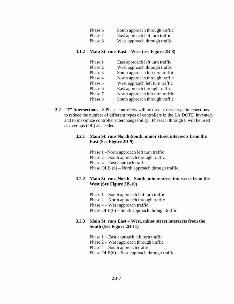
Phase 6 South approach through traffic Phase 7 East approach left turn traffic Phase 8 West approach through traffic
3.1.2 Main St. runs East – West (see Figure 2B-8)
Phase 1 East approach left turn traffic Phase 2 West approach through traffic Phase 3 South approach left turn traffic Phase 4 North approach through traffic Phase 5 West approach left turn traffic Phase 6 East approach through traffic Phase 7 North approach left turn traffic Phase 8 South approach through traffic
3.2 “T” Intersections - 8 Phase controllers will be used at these type intersections
to reduce the number of different types of controllers in the LA DOTD Inventory and to maximize controller interchangeability. Phases 5 through 8 will be used as overlaps (OL) as needed.
3.2.1 Main St. runs North-South, minor street intersects from the
East (See Figure 2B-9) Phase 1 –North approach left turn traffic Phase 2 – South approach through traffic Phase 4 – East approach traffic Phase OLB (6) – North approach through traffic
3.2.2 Main St. runs North – South, minor street intersects from the
West (See Figure 2B-10) Phase 1 – South approach left turn traffic Phase 2 – North approach through traffic Phase 4 – West approach traffic Phase OLB(6) – South approach through traffic
3.2.3 Main St. runs East – West, minor street intersects from the
South (See Figure 2B-11) Phase 1 – East approach left turn traffic Phase 2 – West approach through traffic Phase 4 – South approach traffic Phase OLB(6) – East approach through traffic
2B-7
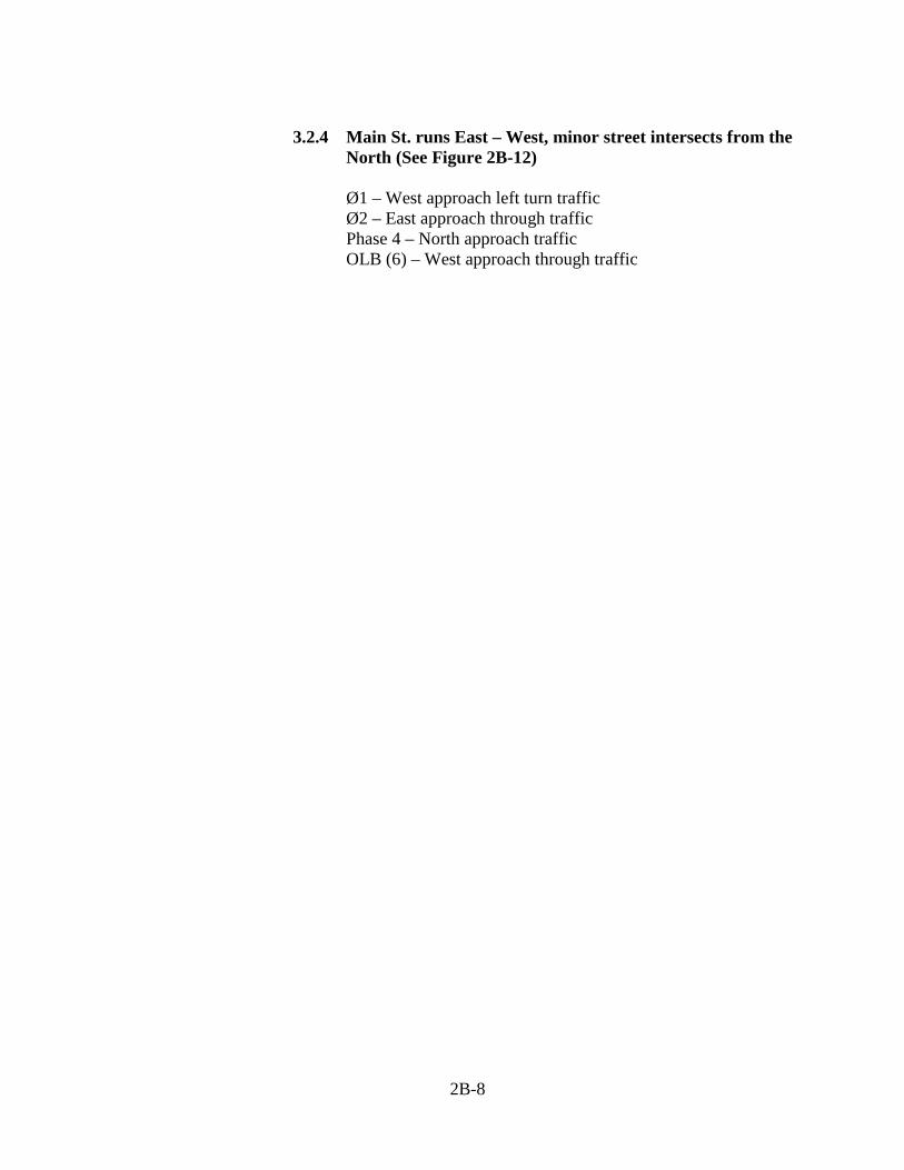
3.2.4 Main St. runs East – West, minor street intersects from the
North (See Figure 2B-12) Ø1 – West approach left turn traffic Ø2 – East approach through traffic Phase 4 – North approach traffic OLB (6) – West approach through traffic
2B-8
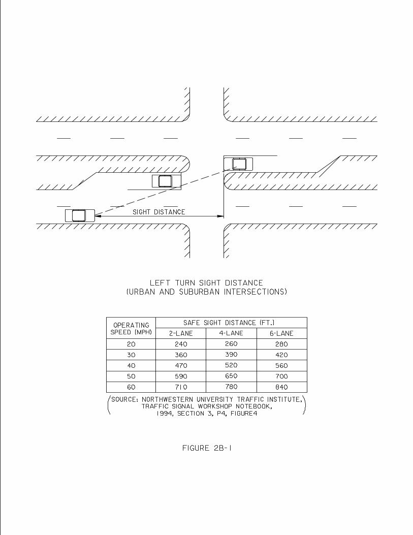
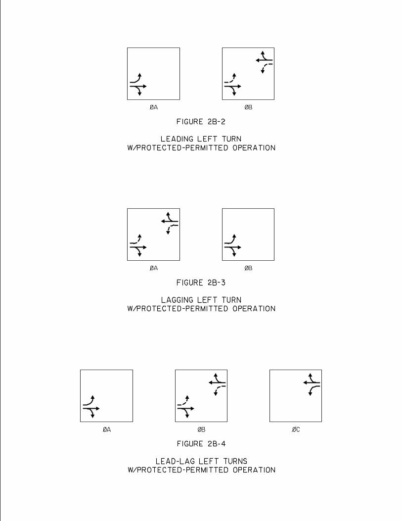
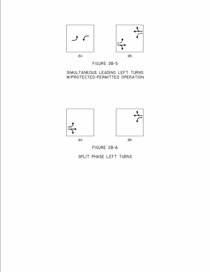
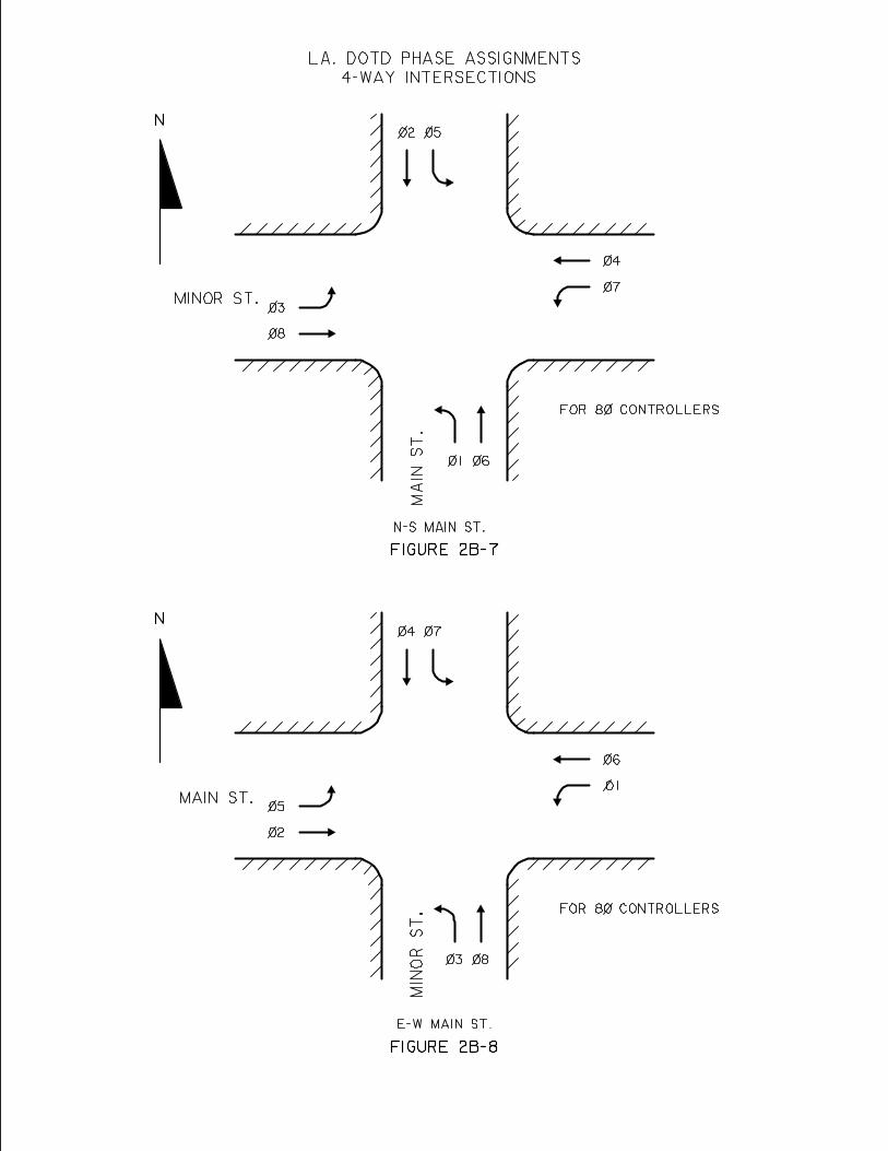
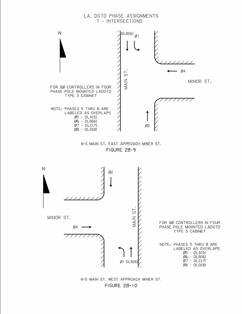
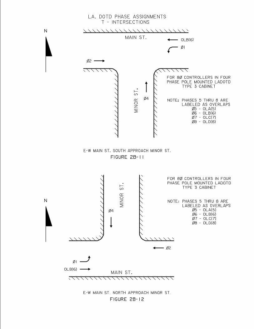
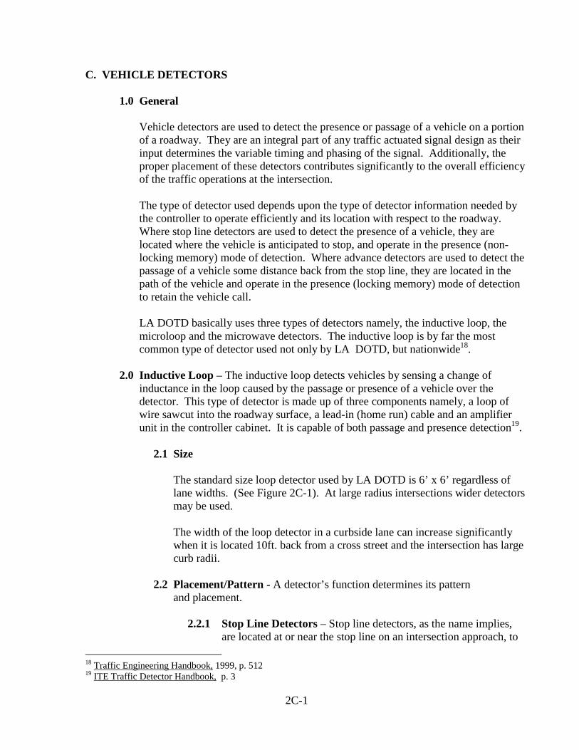
C. VEHICLE DETECTORS
1.0 General
Vehicle detectors are used to detect the presence or passage of a vehicle on a portion of a roadway. They are an integral part of any traffic actuated signal design as their input determines the variable timing and phasing of the signal. Additionally, the proper placement of these detectors contributes significantly to the overall efficiency of the traffic operations at the intersection. The type of detector used depends upon the type of detector information needed by the controller to operate efficiently and its location with respect to the roadway. Where stop line detectors are used to detect the presence of a vehicle, they are located where the vehicle is anticipated to stop, and operate in the presence (non-locking memory) mode of detection. Where advance detectors are used to detect the passage of a vehicle some distance back from the stop line, they are located in the path of the vehicle and operate in the presence (locking memory) mode of detection to retain the vehicle call. LA DOTD basically uses three types of detectors namely, the inductive loop, the microloop and the microwave detectors. The inductive loop is by far the most common type of detector used not only by LA DOTD, but nationwide18.
2.0 Inductive Loop – The inductive loop detects vehicles by sensing a change of
inductance in the loop caused by the passage or presence of a vehicle over the detector. This type of detector is made up of three components namely, a loop of wire sawcut into the roadway surface, a lead-in (home run) cable and an amplifier unit in the controller cabinet. It is capable of both passage and presence detection19.
2.1 Size The standard size loop detector used by LA DOTD is 6’ x 6’ regardless of lane widths. (See Figure 2C-1). At large radius intersections wider detectors may be used.
The width of the loop detector in a curbside lane can increase significantly when it is located 10ft. back from a cross street and the intersection has large curb radii.
2.2 Placement/Pattern - A detector’s function determines its pattern and placement.
2.2.1 Stop Line Detectors – Stop line detectors, as the name implies,
are located at or near the stop line on an intersection approach, to 18 Traffic Engineering Handbook, 1999, p. 512 19 ITE Traffic Detector Handbook, p. 3
2C-1
detect the presence of stopped vehicles and operate in the “presence (non-locking memory)” mode of detection. Accordingly, Stop Line detection is used in through lanes on minor approaches and in left turn lanes on both major and minor approaches (See Figures 2C-2 and 2C-3). When so used they can screen out right turns made on red, or left turns made on left turn permitted signal phases thus preventing false calls. Consideration should also be given to installing stop line detectors in left turn lanes on major approaches that are not protected with a left turn arrow. Such detectors can hold the green phase while the left turn vehicle waits for possible gaps in opposing traffic.
2.2.2 Advance Detectors – Advance detectors are used only with
volume density controllers and are located some distance in advance of the approach stop line. They are located in the through lanes of the major street. These detectors operate in a presence (locking memory) mode and detect the passage of a vehicle. Advance detectors can provide the controller with advance information on vehicles approaching the intersection and, in the case of a volume density controller, can count the number of vehicles on the approach that are waiting with a red signal indication. The location of these detectors is based on the safe stopping distance of approaching vehicles which varies according to the approach speed (See Figure 2C-4)20.
2.3 Detector Wiring – The wiring for each detector or detector pattern in a lane shall
consist of a continuous length of #16 AWG (containing 19 strands of #29 AWG copper wire) IMSA 51-7 wire run from the junction box, through the detector(s) (with three turns in each detector) and back to the junction box. When detectors in adjacent lanes operate the same signal phase, their wiring shall be spliced in series in the junction box. A 1-2 conductor (loop lead-in/#16 AWG) “home run” cable is then run for this signal phase from the junction box to the signal controller cabinet. (See Figure 2C-5).
2.4 Detector Card/Channel Assignments – The following detector card/channel phase assignments shall be used when using 4 – channel detector cards.
Phase Detector Card/Channel 1 1 1/1 2 2 1/2
3 3 1/3 4 4 1/4 5 5 2/1 20 Kell and Fullerton, ITE Manual of Traffic Signal Design, 1991, p. 89
2C-2
6 6 2/2 7 7 2/3 8 8 2/4 Other Function S-1 3/1 Other Function S-2 3/2 Other Function S-3 3/3 Other Function S-4 3/4 Other Function S-5 4/1 Other Function S-6 4/2 Other Function S-7 4/3 Other Function S-8 4/4
3.0 Microloop – A microloop is a transducer that converts changes in the vertical component of the earth’s magnetic field to changes in inductance. Vehicles passing over the detector focus the earth’s magnetic field which causes a change in inductance and thus they are detected. This type of detector is made up of a probe in or under the roadway surface, a lead in (home run) cable and or amplifier unit in controller cabinet21. It is most applicable when attached under bridge decks where saw cutting the roadway surface is discouraged. Since this detector can only detect the passage of a vehicle it is only used as an advance detector. Normally two detectors are needed per lane to assure the detection of motorcycles. As shown in Figure 2C-6, these two detectors are placed four (4’) apart and centered in the approach lane. Figure 2C-4 can be used to determine the probe’s placement back from the approach stop line.
4.0 Microwave – Microwave detectors operate on the same principle as radar detectors
in that they measure the frequency difference between the sent and received signal caused by the arrival or passage of a vehicle22. This type of detector is made up of a pole or mast arm mounted radar unit, a “home run” cable, a controller cabinet mounted RS – 232 connector and a 12 volt power supply. Depending upon type, location and orientation some microloops can detect in both the passage and presence of a vehicle. Accordingly, it can be used in basically the same way as the inductive loops. (See Figure 2C-7 & 2C-8) The microwave detector is also a quick and easy substitute for a defective inductive loop for a major traffic movement.
21 Traffic Engineering Handbook, 1999, p. 512 22 Traffic Engineering Handbook, 1999, p. 513
2C-3
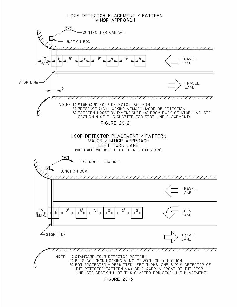
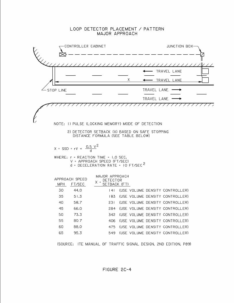
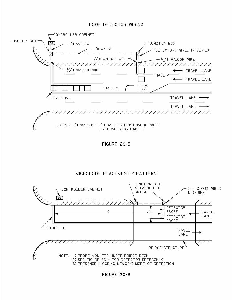
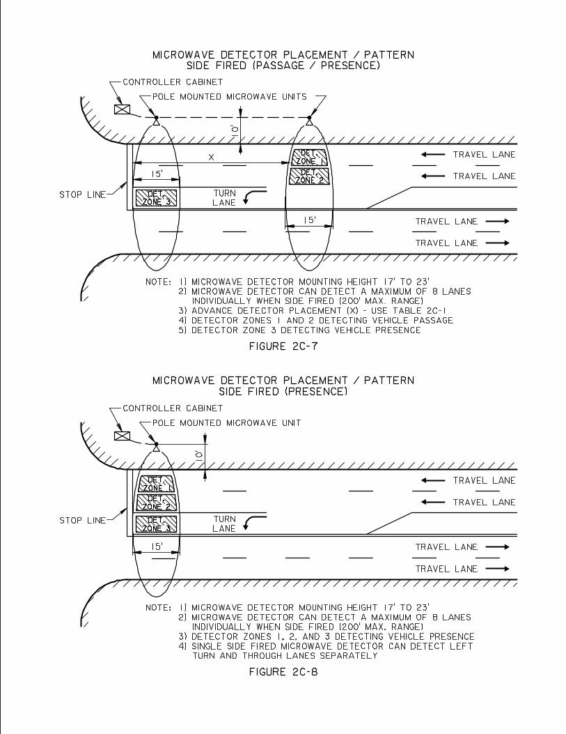
D. SIGNAL TIMING – Proper signal timing is essential to the efficient operation of a signalized intersection. The objective of signal timing is to determine the appropriate timing for each required signal phase so as to minimize the average delay to any single group of vehicles or pedestrians and to reduce the probability of conflicts that could cause accidents23. The timing of a traffic signal should be such that the level of service on the state highway is at least one level of service or higher than that for the minor street. Where both intersecting roadways are state highways, the signal timing should be such as to have the same level of service on both roadways. Regardless of how precise a theoretical method of signal timing might be, its effectiveness for actual traffic conditions must be observed in the field and appropriate timing adjustments made if necessary24.
1.0 Cycle length – Once the signal’s phasing has been decided upon using the guidelines in section B of this chapter, the cycle length of the signal must then be determined. A signal’s cycle length is defined as the total time in seconds required to complete a prescribed sequence of signal phases. In general, signal cycles should be as short as possible to adequately handle the traffic demand and should fall within the following ranges25:
2 Phase 40-80 Seconds 3 Phase 60-100 Seconds 4 Phase 80-120 Seconds
1.1 Cycle Length Determination – Cycle lengths should be calculated for the
AM Peak hour, the PM Peak hour and the off peak periods as a minimum. If the cycle lengths are significantly different from one another (10 seconds or more), then each period would operate on a different cycle length. There are several methods used to calculate cycle lengths, two of which are provided below.
1.1.1 Critical Lane Volume Method 26–The sum of the critical lane
volumes for each signal phase can be used to determine a minimum cycle length. The first step is assigning peak hour approach volumes to individual lanes as follows:
• Exclusive Turn Lanes – Where exclusive turn lanes are
available, all turns are assigned to the appropriate turn lane. The remaining approach through volumes are equally distributed to the approach through lanes.
• Shared Lanes without permissive left turns – For shared
and/or through lanes where permissive left turns are not
23 Northwestern University, Traffic Institute, Traffic Signal Workshop Notebook, 1994, Section 4, p. 2 24 Northwestern University, Traffic Institute, Traffic Signal Workshop Notebook, 1994, Section 4, p. 3 25 Northwestern University, Traffic Institute, Traffic Signal Workshop Notebook, 1994, Section 4, p. 3 26 Northwestern University, Traffic Institute, Traffic Signal Workshop Notebook, 1994, Section 6, p. 1-4
2D-1
present, the approach volume is equally distributed amongst the approach lanes.
• Shared lanes with permissive left turns
Where permissive left turns are present in shared lanes, the left turn volumes must be converted to through vehicle equivalents (TVE) using Table 2D-1. They are then added to the through and right turn volumes on the approach and equally distributed to the approach lanes. The total TVE left turn volume is then subtracted from the inside (left) shared lane volume to determine the actual number of through vehicles in that lane. This actual number of through vehicles is added to the actual left turn volume and assigned to the shared inside (left) lane. The actual remaining traffic is then distributed equally to the remaining approach lanes. The highest lane volume for this approach is critical lane volume for the approach. (See Figure 2D-1)
• Using the assumed signal phasing, the highest lane volume
moving in each phase is identified as the critical lane volume for that phase.
• The critical lane volume for all phases is totaled and Table
2D-2 is used to determine the minimum cycle length.
1.1.2 Signal Timing Software – WIN TEAPAC 2000, SIGNAL 2000 software provides a relatively quick and easy method of determining how well a range of cycle lengths will work for a given set of conditions at an intersection. The procedure used is as follows:
• Under “Edit” choose “Movement” and enter the following
information: Volumes Widths Lanes Required Clearances
2D-2
Minimum Greens
• Under “Edit” choose “Phasing” and enter the following information: Sequences
Permissives Overlaps Lead/Lag Range of cycles with increments Pedestrian Timing
• Under “Results” choose “Design” which will give the level
of service for a range of cycles and phases. Generally the lowest cycle length with the best level of service for the phasing desired is chosen.
1.2 Signal Systems
1.2.1 Existing System – Where a signal is to be added to an existing
signal system, it must operate on the same cycle length as the system or a multiple of it.
1.2.2 New System - If individual signals are being timed for a new
signal system, the intersection requiring the longest cycle lengths is the “critical intersection” and its cycle length will determine the cycle length for the system.
2.0 Pretimed (fixed time) Controller Timing – As previously defined a pretimed
controller is one in which the timing and phasing do not vary from cycle to cycle. Once a cycle length has been chosen, the basic timing parameters for a pretimed controller are the green interval and clearance interval for each phase. Additionally, if pedestrian crossings are a consideration, pedestrian timing will also have to be considered with or without pedestrian signal indications.
2.1 Green Interval Timing – With solid state equipment the green time for each
phase is set on maximum recall because of the lack of signal detection. This setting for each phase is based on the average needs for that particular movement as determined by traffic counts. Ideally it should be long enough to service all the vehicles and pedestrians accumulated during the red interval27. Two methods of calculating the maximum green time is as follows:
2.1.1. Manual calculation – The green interval timing can be calculated for each phase by equation 2D-1.
27 Traffic Engineering Handbook, 1999, p. 480
2D-3
Equation 2D-1
CLRxCVVG
T
A −
=
Where: G = Green interval for phase (sec.) AV = Critical lane volume for phase (veh/hr.) TV = Sum of critical lane volumes for all phases (veh/hr.)
C = Cycle Length CLR = Clearance interval for phase (sec.)
2.1.2 Signal Timing Software – WIN TEAPAC 2000, Signal 2000 software provides a relatively quick and easy method of determine optimium green phase setting while minimizing the approach and overall intersection delay. The procedure used is as follows:
• Under “Edit” choose “Movement” and enter the following
information Volumes Width Lanes
Group Types (normal, free flow, dual optional) Peak Hour Factors Arrival Types Actuations (enter “No” for all movements) Required Clearances • Under “Edit” choose “Phasing” and enter the following
information Sequences Permissives Overlaps Lead Lag Cycles (set max cycle and min cycle equal) Ped Time • Under “Results” execute “Design” and “Timing” which
will give you an optimum timing for the phasing and cycle length you have chosen. Additionally executing “Analyze” will give a capacity/delay analysis for the intersections to see if further timing adjustments are needed to adjust the individual approach and overall intersection delay.
2.1.3 Peak Hour Factor (PHF) – The peak hour factor, used in signal
timing software such as WIN TEAPAC 2000, SIGNAL 2000, is a measure of the consistency of the traffic demand for a peak hour.
2D-4
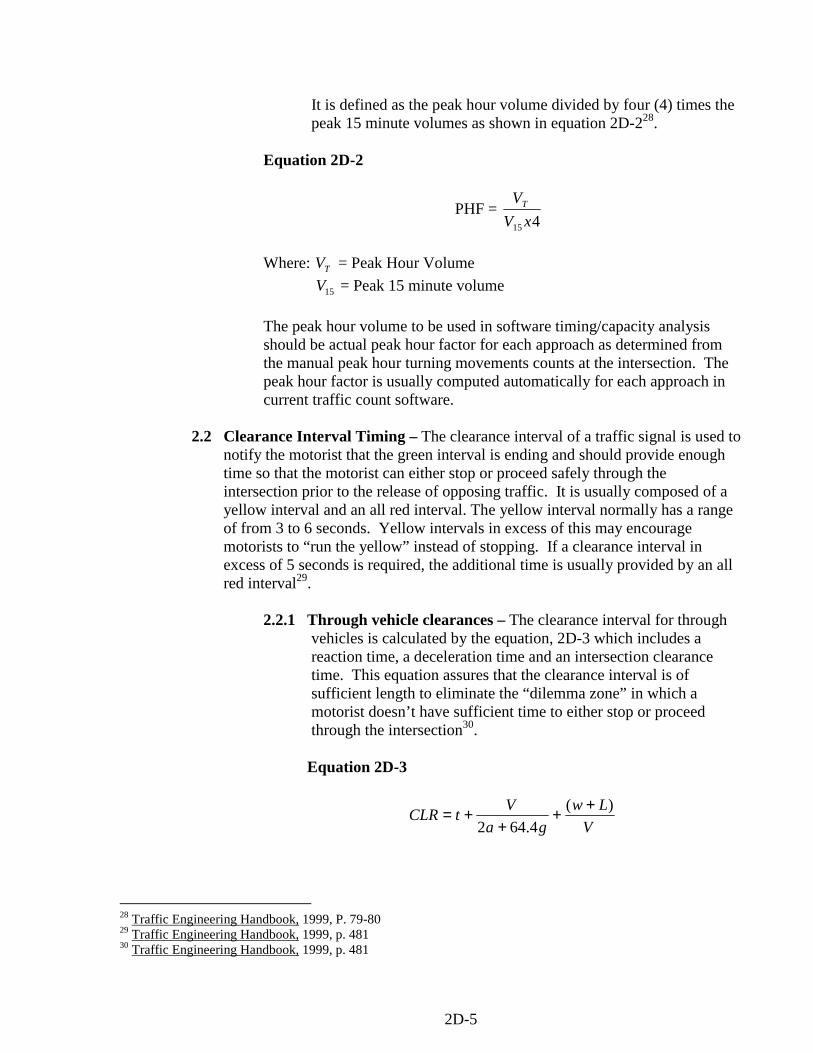
It is defined as the peak hour volume divided by four (4) times the peak 15 minute volumes as shown in equation 2D-228.
Equation 2D-2
PHF = 415 xV
VT
Where: TV = Peak Hour Volume 15V = Peak 15 minute volume
The peak hour volume to be used in software timing/capacity analysis should be actual peak hour factor for each approach as determined from the manual peak hour turning movements counts at the intersection. The peak hour factor is usually computed automatically for each approach in current traffic count software.
2.2 Clearance Interval Timing – The clearance interval of a traffic signal is used to
notify the motorist that the green interval is ending and should provide enough time so that the motorist can either stop or proceed safely through the intersection prior to the release of opposing traffic. It is usually composed of a yellow interval and an all red interval. The yellow interval normally has a range of from 3 to 6 seconds. Yellow intervals in excess of this may encourage motorists to “run the yellow” instead of stopping. If a clearance interval in excess of 5 seconds is required, the additional time is usually provided by an all red interval29.
2.2.1 Through vehicle clearances – The clearance interval for through
vehicles is calculated by the equation, 2D-3 which includes a reaction time, a deceleration time and an intersection clearance time. This equation assures that the clearance interval is of sufficient length to eliminate the “dilemma zone” in which a motorist doesn’t have sufficient time to either stop or proceed through the intersection30.
Equation 2D-3
VLw
gaVtCLR )(
4.642++
++=
28 Traffic Engineering Handbook, 1999, P. 79-80 29 Traffic Engineering Handbook, 1999, p. 481 30 Traffic Engineering Handbook, 1999, p. 481
2D-5
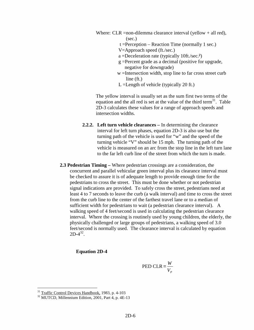
Where: CLR =non-dilemma clearance interval (yellow + all red), (sec.) t =Perception – Reaction Time (normally 1 sec.) V=Approach speed (ft./sec.) a =Deceleration rate (typically 10ft./sec.²) g =Percent grade as a decimal (positive for upgrade, negative for downgrade) w =Intersection width, stop line to far cross street curb line (ft.) L =Length of vehicle (typically 20 ft.)
The yellow interval is usually set as the sum first two terms of the equation and the all red is set at the value of the third term31. Table 2D-3 calculates these values for a range of approach speeds and intersection widths.
2.2.2. Left turn vehicle clearances – In determining the clearance
interval for left turn phases, equation 2D-3 is also use but the turning path of the vehicle is used for “w” and the speed of the turning vehicle “V” should be 15 mph. The turning path of the vehicle is measured on an arc from the stop line in the left turn lane to the far left curb line of the street from which the turn is made.
2.3 Pedestrian Timing – Where pedestrian crossings are a consideration, the
concurrent and parallel vehicular green interval plus its clearance interval must be checked to assure it is of adequate length to provide enough time for the pedestrians to cross the street. This must be done whether or not pedestrian signal indications are provided. To safely cross the street, pedestrians need at least 4 to 7 seconds to leave the curb (a walk interval) and time to cross the street from the curb line to the center of the farthest travel lane or to a median of sufficient width for pedestrians to wait (a pedestrian clearance interval). A walking speed of 4 feet/second is used in calculating the pedestrian clearance interval. Where the crossing is routinely used by young children, the elderly, the physically challenged or large groups of pedestrians, a walking speed of 3.0 feet/second is normally used. The clearance interval is calculated by equation 2D-432.
Equation 2D-4
PED CLRPV
W=
31 Traffic Control Devices Handbook, 1983, p. 4-103 32 MUTCD, Millennium Edition, 2001, Part 4, p. 4E-13
2D-6
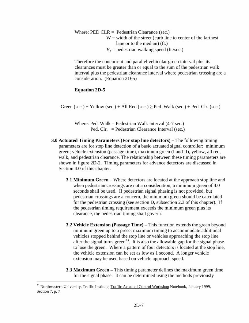
Where: PED CLR = Pedestrian Clearance (sec.) W = width of the street (curb line to center of the farthest lane or to the median) (ft.) PV = pedestrian walking speed (ft./sec.) Therefore the concurrent and parallel vehicular green interval plus its clearances must be greater than or equal to the sum of the pedestrian walk interval plus the pedestrian clearance interval where pedestrian crossing are a consideration. (Equation 2D-5) Equation 2D-5
Green (sec.) + Yellow (sec.) + All Red (sec.) > Ped. Walk (sec.) + Ped. Clr. (sec.) Where: Ped. Walk = Pedestrian Walk Interval (4-7 sec.) Ped. Clr. = Pedestrian Clearance Interval (sec.)
3.0 Actuated Timing Parameters (For stop line detectors) – The following timing
parameters are for stop line detection of a basic actuated signal controller: minimum green; vehicle extension (passage time), maximum green (I and II), yellow, all red, walk, and pedestrian clearance. The relationship between these timing parameters are shown in figure 2D-2. Timing parameters for advance detectors are discussed in Section 4.0 of this chapter.
3.1 Minimum Green – Where detectors are located at the approach stop line and
when pedestrian crossings are not a consideration, a minimum green of 4.0 seconds shall be used. If pedestrian signal phasing is not provided, but pedestrian crossings are a concern, the minimum green should be calculated for the pedestrian crossing (see section D, subsection 2.3 of this chapter). If the pedestrian timing requirement exceeds the minimum green plus its clearance, the pedestrian timing shall govern.
3.2 Vehicle Extension (Passage Time) – This function extends the green beyond
minimum green up to a preset maximum timing to accommodate additional vehicles stopped behind the stop line or vehicles approaching the stop line after the signal turns green33. It is also the allowable gap for the signal phase to lose the green. Where a pattern of four detectors is located at the stop line, the vehicle extension can be set as low as 1 second. A longer vehicle extension may be used based on vehicle approach speed.
3.3 Maximum Green – This timing parameter defines the maximum green time for the signal phase. It can be determined using the methods previously
33 Northwestern University, Traffic Institute, Traffic Actuated Control Workshop Notebook, January 1999, Section 7, p. 7
2D-7
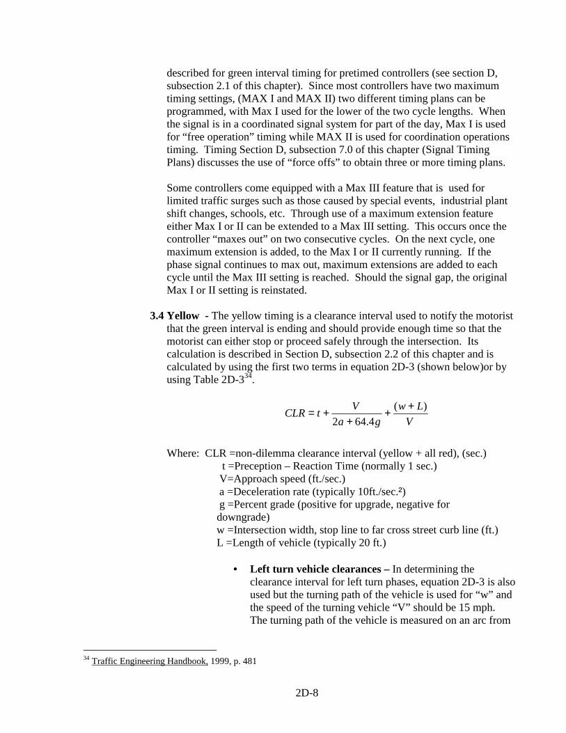
described for green interval timing for pretimed controllers (see section D, subsection 2.1 of this chapter). Since most controllers have two maximum timing settings, (MAX I and MAX II) two different timing plans can be programmed, with Max I used for the lower of the two cycle lengths. When the signal is in a coordinated signal system for part of the day, Max I is used for “free operation” timing while MAX II is used for coordination operations timing. Timing Section D, subsection 7.0 of this chapter (Signal Timing Plans) discusses the use of “force offs” to obtain three or more timing plans.
Some controllers come equipped with a Max III feature that is used for limited traffic surges such as those caused by special events, industrial plant shift changes, schools, etc. Through use of a maximum extension feature either Max I or II can be extended to a Max III setting. This occurs once the controller “maxes out” on two consecutive cycles. On the next cycle, one maximum extension is added, to the Max I or II currently running. If the phase signal continues to max out, maximum extensions are added to each cycle until the Max III setting is reached. Should the signal gap, the original Max I or II setting is reinstated.
3.4 Yellow - The yellow timing is a clearance interval used to notify the motorist
that the green interval is ending and should provide enough time so that the motorist can either stop or proceed safely through the intersection. Its calculation is described in Section D, subsection 2.2 of this chapter and is calculated by using the first two terms in equation 2D-3 (shown below)or by using Table 2D-334.
VLw
gaVtCLR )(
4.642++
++=
Where: CLR =non-dilemma clearance interval (yellow + all red), (sec.) t =Preception – Reaction Time (normally 1 sec.) V=Approach speed (ft./sec.) a =Deceleration rate (typically 10ft./sec.²) g =Percent grade (positive for upgrade, negative for downgrade) w =Intersection width, stop line to far cross street curb line (ft.) L =Length of vehicle (typically 20 ft.)
• Left turn vehicle clearances – In determining the clearance interval for left turn phases, equation 2D-3 is also used but the turning path of the vehicle is used for “w” and the speed of the turning vehicle “V” should be 15 mph. The turning path of the vehicle is measured on an arc from
34 Traffic Engineering Handbook, 1999, p. 481
2D-8
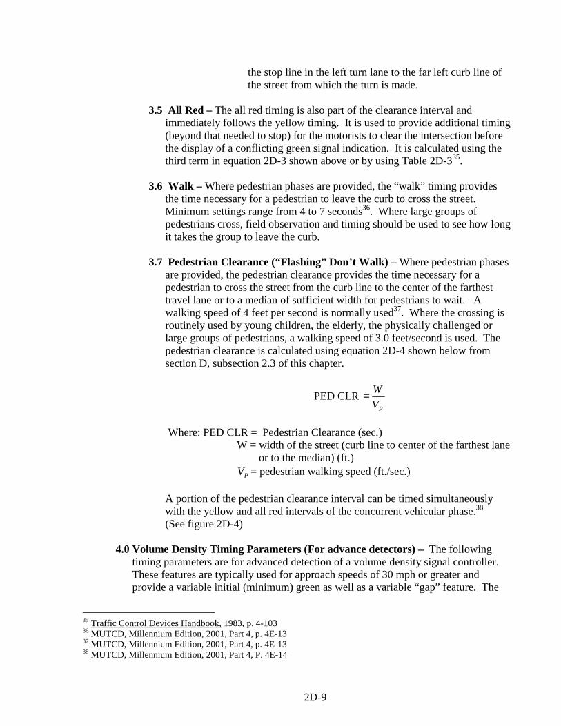
the stop line in the left turn lane to the far left curb line of the street from which the turn is made.
3.5 All Red – The all red timing is also part of the clearance interval and
immediately follows the yellow timing. It is used to provide additional timing (beyond that needed to stop) for the motorists to clear the intersection before the display of a conflicting green signal indication. It is calculated using the third term in equation 2D-3 shown above or by using Table 2D-335.
3.6 Walk – Where pedestrian phases are provided, the “walk” timing provides
the time necessary for a pedestrian to leave the curb to cross the street. Minimum settings range from 4 to 7 seconds36. Where large groups of pedestrians cross, field observation and timing should be used to see how long it takes the group to leave the curb.
3.7 Pedestrian Clearance (“Flashing” Don’t Walk) – Where pedestrian phases
are provided, the pedestrian clearance provides the time necessary for a pedestrian to cross the street from the curb line to the center of the farthest travel lane or to a median of sufficient width for pedestrians to wait. A walking speed of 4 feet per second is normally used37. Where the crossing is routinely used by young children, the elderly, the physically challenged or large groups of pedestrians, a walking speed of 3.0 feet/second is used. The pedestrian clearance is calculated using equation 2D-4 shown below from section D, subsection 2.3 of this chapter.
PED CLR PV
W=
Where: PED CLR = Pedestrian Clearance (sec.)
W = width of the street (curb line to center of the farthest lane or to the median) (ft.) PV = pedestrian walking speed (ft./sec.) A portion of the pedestrian clearance interval can be timed simultaneously with the yellow and all red intervals of the concurrent vehicular phase.38 (See figure 2D-4)
4.0 Volume Density Timing Parameters (For advance detectors) – The following timing parameters are for advanced detection of a volume density signal controller. These features are typically used for approach speeds of 30 mph or greater and provide a variable initial (minimum) green as well as a variable “gap” feature. The
35 Traffic Control Devices Handbook, 1983, p. 4-103 36 MUTCD, Millennium Edition, 2001, Part 4, p. 4E-13 37 MUTCD, Millennium Edition, 2001, Part 4, p. 4E-13 38 MUTCD, Millennium Edition, 2001, Part 4, P. 4E-14
2D-9

timing parameters are: minimum initial (minimum green), added initial, initial gap (passage time), time before reduction, time to reduce, minimum gap, maximum green (I and II), yellow, all red, walk, and pedestrian clearance. The timing relationship between these parameters are shown in figure 2D-3. The timing of each parameter is as follow:
4.1 Minimum Initial (minimum green) – This function provides the guaranteed
minimum green for the signal phase. Because of the added initial feature, the minimum initial does not have to be long enough to start up and clear the intersection all the vehicles waiting between the stop line and the detector.39 Instead it is usually set between 10-15 seconds so as not to violate motorists expectancy on a major high speed approach. If pedestrian signal phasing is not provided but pedestrian crossings are a concern, the minimum green should also be calculated for the pedestrian crossing (see section D, subsection 2.3 of this chapter). If the length of the required pedestrian phase exceeds the 10-15 second minimum initial, then its timing should be used for the minimum initial setting.
4.2 Maximum Initial40 – Some controllers come equipped with a maximum
initial setting. This is the maximum timing to which the variable initial interval can be extended. It is the timing necessary to clear a queue of vehicles that extends from the stop line to the detector. Assuming a start up delay of 4 seconds and a discharge rate of 2 seconds per vehicle, the maximum initial is calculated by the following equation.
Equation 2D-6 MI (sec.) = 4 + 2n Where : MI = Maximum Initial n = Distance for stop line to the detector divided by 20 ft/vehicle (Source = Northwestern University Traffic Institute, Traffic Actuated Contract Workshop Notebook, September 1994)
39 Northwestern University, Traffic Institute, Traffic Actuated Control Workshop Notebook, January 1999, Section 7, p. 11 40 Northwestern University, Traffic Institute, Traffic Actuated Control Workshop Notebook, January 1999, Section 7, p. 6, 11-12
2D-10
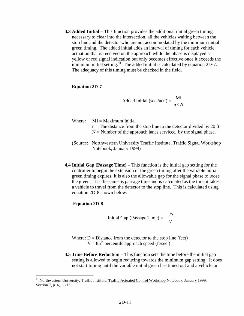
4.3 Added Initial – This function provides the additional initial green timing necessary to clear into the intersection, all the vehicles waiting between the stop line and the detector who are not accommodated by the minimum initial green timing. The added initial adds an interval of timing for each vehicle actuation that is received on the approach while the phase is displayed a yellow or red signal indication but only becomes effective once it exceeds the minimum initial setting.41 The added initial is calculated by equation 2D-7. The adequacy of this timing must be checked in the field.
Equation 2D-7
Added Initial (sec./act.) = Nn×
MI
Where: MI = Maximum Initial n = The distance from the stop line to the detector divided by 20 ft. N = Number of the approach lanes serviced by the signal phase. (Source: Northwestern University Traffic Institute, Traffic Signal Workshop Notebook, January 1999)
4.4 Initial Gap (Passage Time) – This function is the initial gap setting for the controller to begin the extension of the green timing after the variable initial green timing expires. It is also the allowable gap for the signal phase to loose the green. It is the same as passage time and is calculated as the time it takes a vehicle to travel from the detector to the stop line. This is calculated using equation 2D-8 shown below.
Equation 2D-8
Initial Gap (Passage Time) = VD
Where: D = Distance from the detector to the stop line (feet) V = 85th percentile approach speed (ft/sec.) 4.5 Time Before Reduction – This function sets the time before the initial gap
setting is allowed to begin reducing towards the minimum gap setting. It does not start timing until the variable initial green has timed out and a vehicle or
41 Northwestern University, Traffic Institute, Traffic Actuated Control Workshop Notebook, January 1999, Section 7, p. 6, 11-12
2D-11
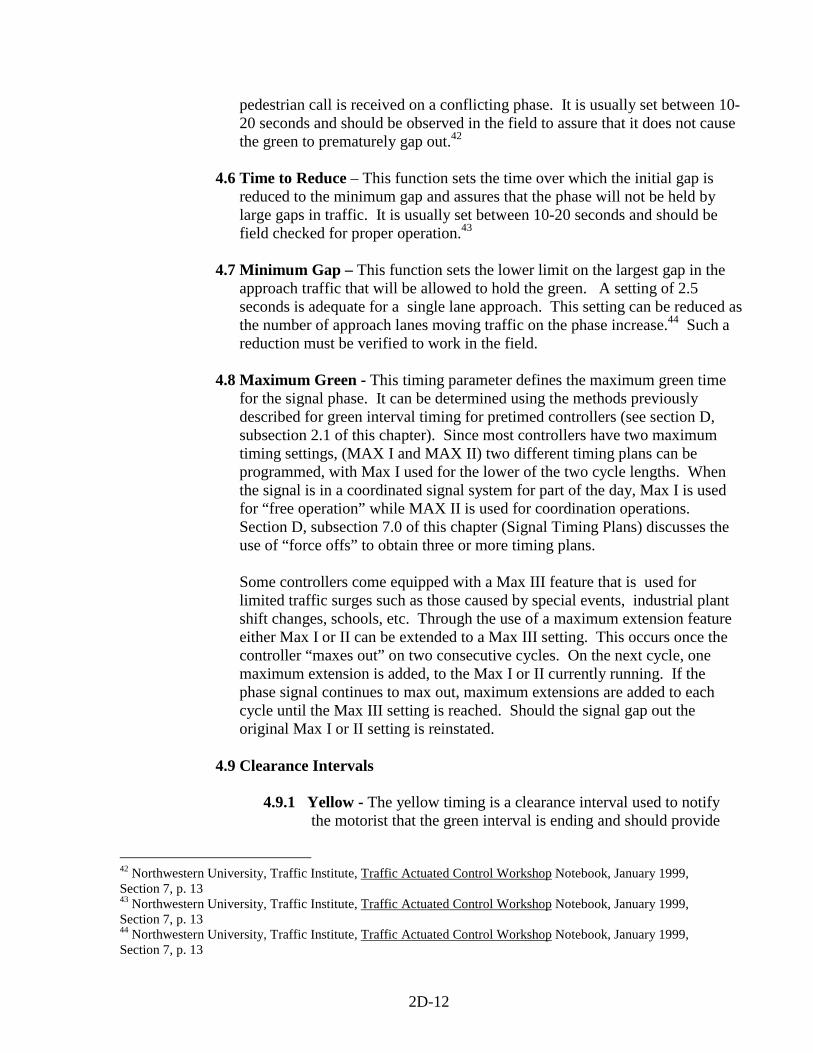
pedestrian call is received on a conflicting phase. It is usually set between 10-20 seconds and should be observed in the field to assure that it does not cause the green to prematurely gap out.42
4.6 Time to Reduce – This function sets the time over which the initial gap is
reduced to the minimum gap and assures that the phase will not be held by large gaps in traffic. It is usually set between 10-20 seconds and should be field checked for proper operation.43
4.7 Minimum Gap – This function sets the lower limit on the largest gap in the
approach traffic that will be allowed to hold the green. A setting of 2.5 seconds is adequate for a single lane approach. This setting can be reduced as the number of approach lanes moving traffic on the phase increase.44 Such a reduction must be verified to work in the field.
4.8 Maximum Green - This timing parameter defines the maximum green time
for the signal phase. It can be determined using the methods previously described for green interval timing for pretimed controllers (see section D, subsection 2.1 of this chapter). Since most controllers have two maximum timing settings, (MAX I and MAX II) two different timing plans can be programmed, with Max I used for the lower of the two cycle lengths. When the signal is in a coordinated signal system for part of the day, Max I is used for “free operation” while MAX II is used for coordination operations. Section D, subsection 7.0 of this chapter (Signal Timing Plans) discusses the use of “force offs” to obtain three or more timing plans.
Some controllers come equipped with a Max III feature that is used for limited traffic surges such as those caused by special events, industrial plant shift changes, schools, etc. Through the use of a maximum extension feature either Max I or II can be extended to a Max III setting. This occurs once the controller “maxes out” on two consecutive cycles. On the next cycle, one maximum extension is added, to the Max I or II currently running. If the phase signal continues to max out, maximum extensions are added to each cycle until the Max III setting is reached. Should the signal gap out the original Max I or II setting is reinstated.
4.9 Clearance Intervals
4.9.1 Yellow - The yellow timing is a clearance interval used to notify
the motorist that the green interval is ending and should provide
42 Northwestern University, Traffic Institute, Traffic Actuated Control Workshop Notebook, January 1999, Section 7, p. 13 43 Northwestern University, Traffic Institute, Traffic Actuated Control Workshop Notebook, January 1999, Section 7, p. 13 44 Northwestern University, Traffic Institute, Traffic Actuated Control Workshop Notebook, January 1999, Section 7, p. 13
2D-12
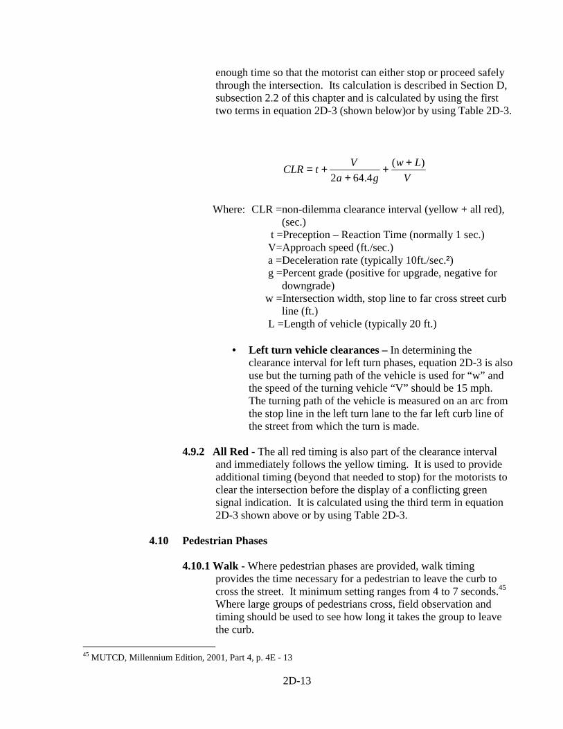
enough time so that the motorist can either stop or proceed safely through the intersection. Its calculation is described in Section D, subsection 2.2 of this chapter and is calculated by using the first two terms in equation 2D-3 (shown below)or by using Table 2D-3.
VLw
gaVtCLR )(
4.642++
++=
Where: CLR =non-dilemma clearance interval (yellow + all red), (sec.) t =Preception – Reaction Time (normally 1 sec.) V=Approach speed (ft./sec.) a =Deceleration rate (typically 10ft./sec.²) g =Percent grade (positive for upgrade, negative for downgrade) w =Intersection width, stop line to far cross street curb line (ft.)
L =Length of vehicle (typically 20 ft.)
• Left turn vehicle clearances – In determining the clearance interval for left turn phases, equation 2D-3 is also use but the turning path of the vehicle is used for “w” and the speed of the turning vehicle “V” should be 15 mph. The turning path of the vehicle is measured on an arc from the stop line in the left turn lane to the far left curb line of the street from which the turn is made.
4.9.2 All Red - The all red timing is also part of the clearance interval
and immediately follows the yellow timing. It is used to provide additional timing (beyond that needed to stop) for the motorists to clear the intersection before the display of a conflicting green signal indication. It is calculated using the third term in equation 2D-3 shown above or by using Table 2D-3.
4.10 Pedestrian Phases
4.10.1 Walk - Where pedestrian phases are provided, walk timing provides the time necessary for a pedestrian to leave the curb to cross the street. It minimum setting ranges from 4 to 7 seconds.45 Where large groups of pedestrians cross, field observation and timing should be used to see how long it takes the group to leave the curb.
45 MUTCD, Millennium Edition, 2001, Part 4, p. 4E - 13
2D-13
4.10.2 Pedestrian Clearance (“Flashing” Don’t Walk) - Where
pedestrian phases are provided, the pedestrian clearance provides the time necessary for a pedestrian to cross the street from the curb line to the center of the farthest travel lane or to a median of sufficient width for pedestrians to wait. A walking speed of 4 feet per second is assumed. It is calculated using equation 2D-4 shown below from section D, subsection 2.3 of this chapter.
PED CLR PV
W=
Where: PED CLR = Pedestrian Clearance (sec.)
W = width of the street (curb line to center of the farthest lane or to the median) (ft.)
PV = pedestrian walking speed (4ft./sec.) A portion of the pedestrian clearance interval can be timed simultaneously with the yellow and all red intervals of the concurrent vehicular phase. (See Figure 2D-4)
5.0 Signal Timing Plans - A signal timing plan is a unique combination of cycle length,
phasing, splits (green + clearance for each phase) and offsets (for system operation).46 Where overall intersection volumes vary significantly during the day, more than one cycle length will be needed. The procedure for determining cycle lengths has been previously discussed in Section D, Subsection 1.0 of this chapter. Where individual traffic movements vary significantly during the day, a change in phase split timing is needed. The procedure for determining the green timing required for the split has been previously discussed in Section D, Subsection 2.1 of this chapter. A change in either cycle length or phase splits will require multiple timing plans. Where only two timing plans are needed, MAX I and MAX II can be used.
5.1 Force Off - Where more than two timing plans are needed or signal coordination is required, MAX II using phase splits (green + clearance for each phase) and “force offs” are used. A “force off” is a function that forces the signal to leave a green phase prior to its maximum setting and starts the clearance for that phase. A different set of phase splits and “force offs” are required for each timing plan. When using the MAX II function for multiple timing plans, it is important that the MAX II timing for each phase be set at a value greater than that required for that phase in any of the timing plans. Figure 2D-5 shows an example of using the MAX II function along with phase splits and “force offs” to produce three different timing plans for a coordinated intersection.
46 Traffic Control Devices Handbook, 1983, p. 4 - 100
2D-14
5.2 Offset – Where adjacent signals are coordinated (interconnected), signal offset settings are needed. An offset is the time difference (in either seconds or percent of cycle) between the start or end of the green at one intersection and the start or end of green at another intersection, both measured from a system time base.47
47 Kell and Fullerton, ITE Manual of Traffic Signal Design, 1991, p. 163
2D-15
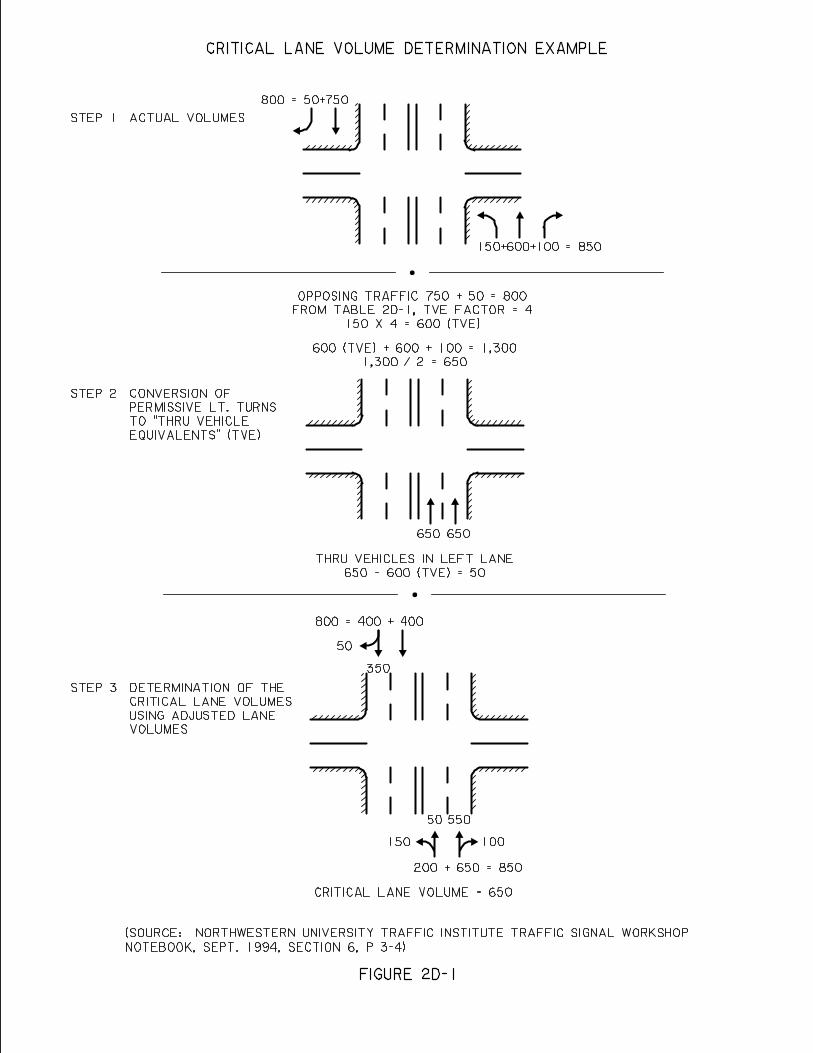
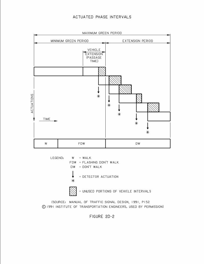
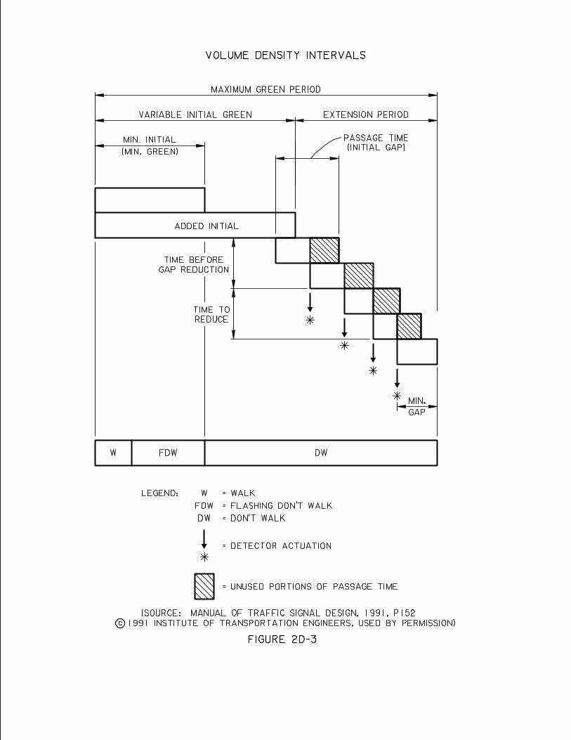
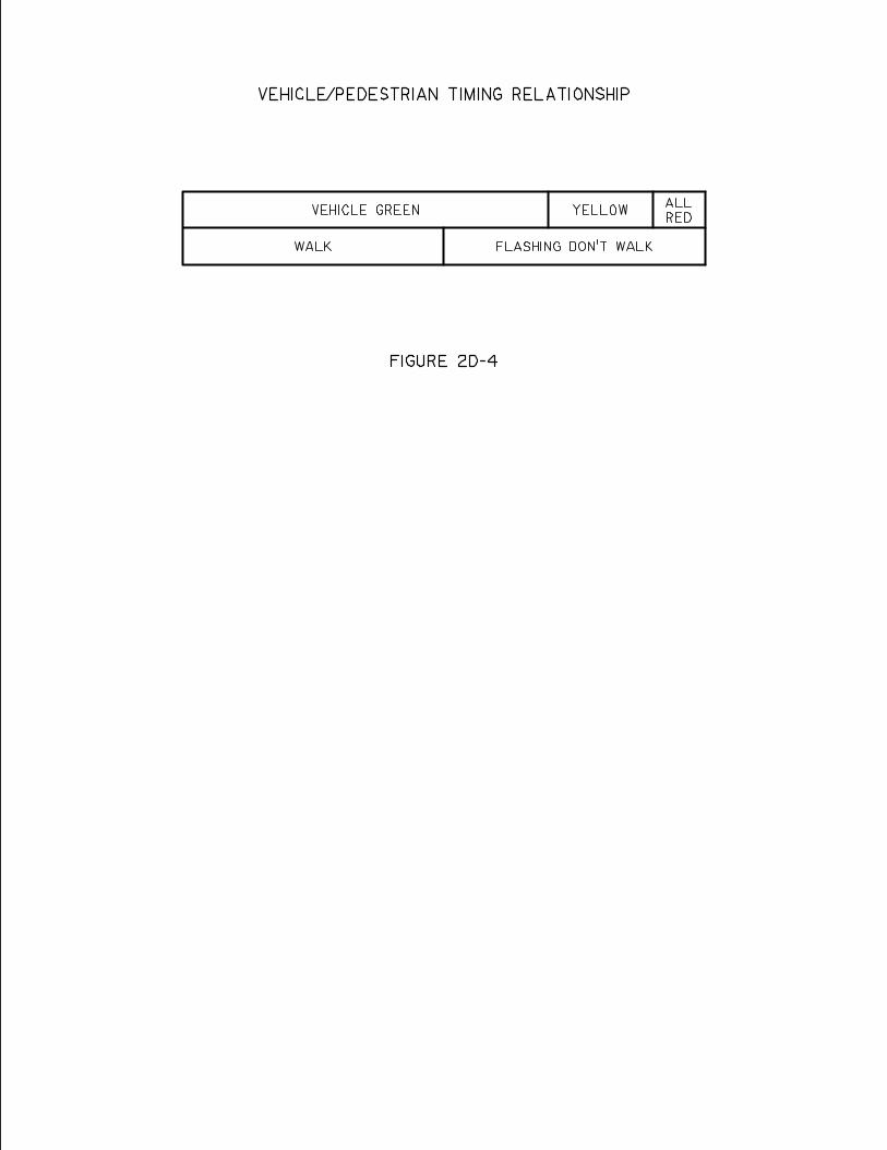
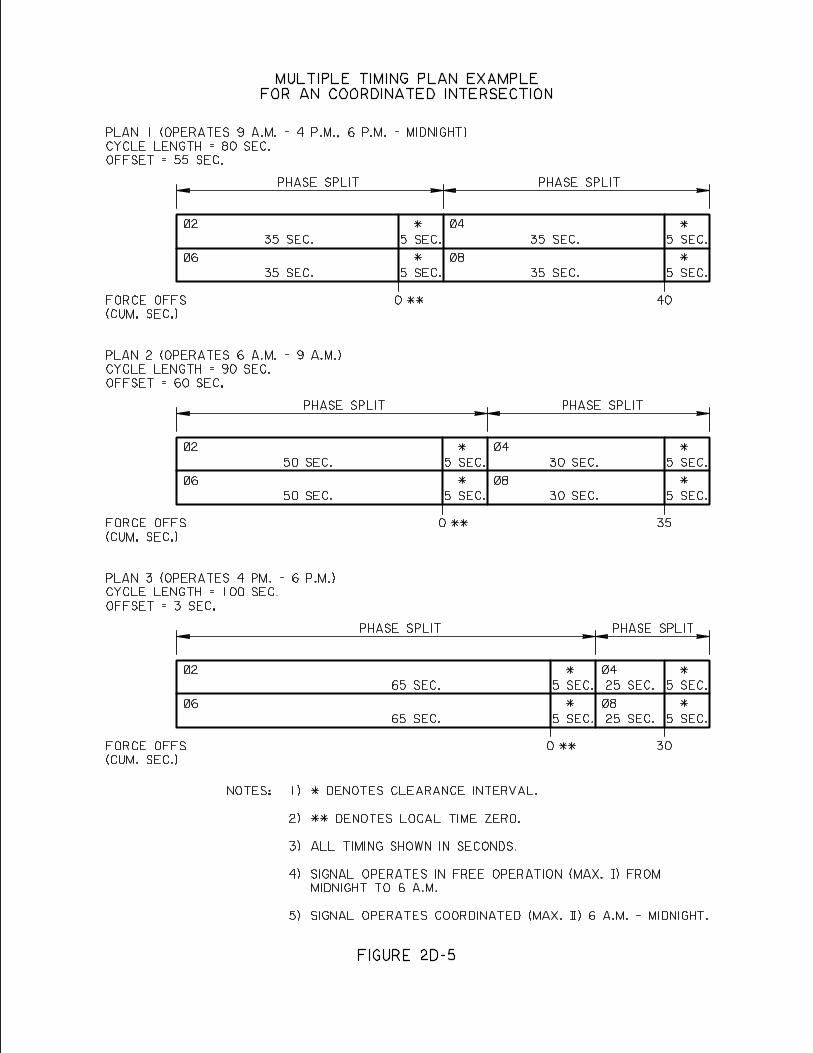
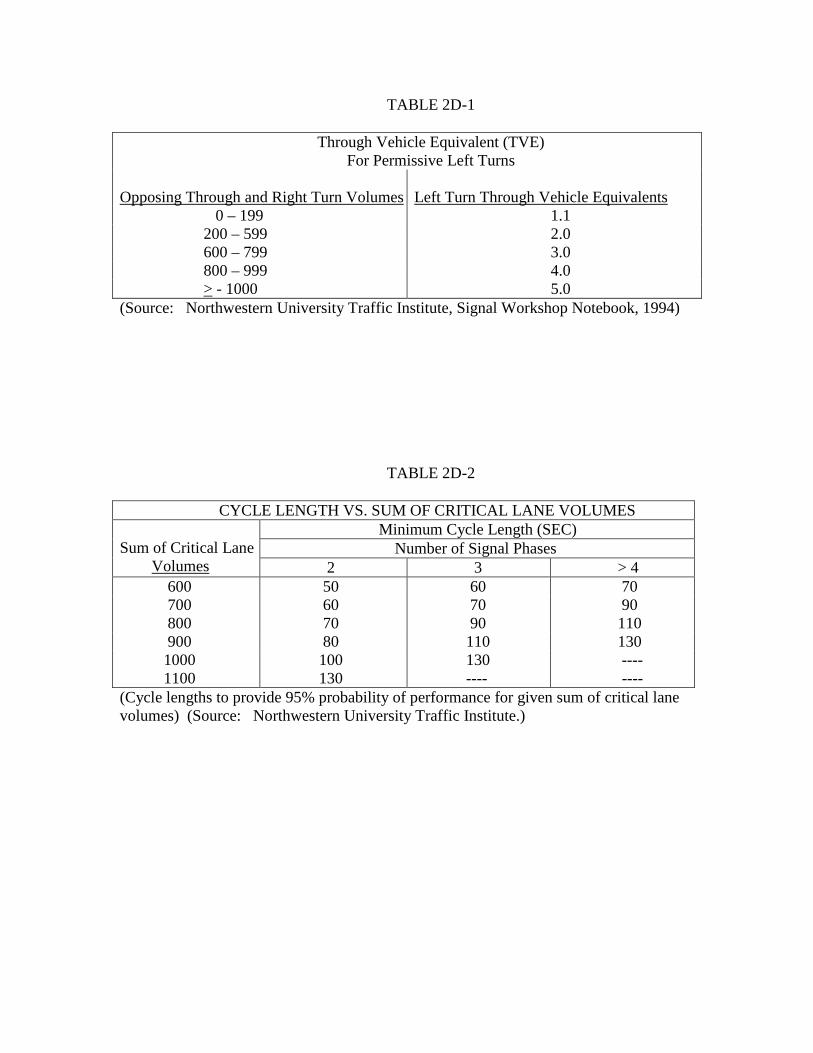
TABLE 2D-1
Through Vehicle Equivalent (TVE) For Permissive Left Turns
Opposing Through and Right Turn Volumes
Left Turn Through Vehicle Equivalents
0 – 199 1.1 200 – 599 2.0 600 – 799 3.0 800 – 999 4.0 > - 1000 5.0
(Source: Northwestern University Traffic Institute, Signal Workshop Notebook, 1994)
TABLE 2D-2
CYCLE LENGTH VS. SUM OF CRITICAL LANE VOLUMES Minimum Cycle Length (SEC) Number of Signal Phases
Sum of Critical Lane Volumes 2 3 > 4 600 50 60 70 700 60 70 90 800 70 90 110 900 80 110 130 1000 100 130 ---- 1100 130 ---- ---- (Cycle lengths to provide 95% probability of performance for given sum of critical lane volumes) (Source: Northwestern University Traffic Institute.)
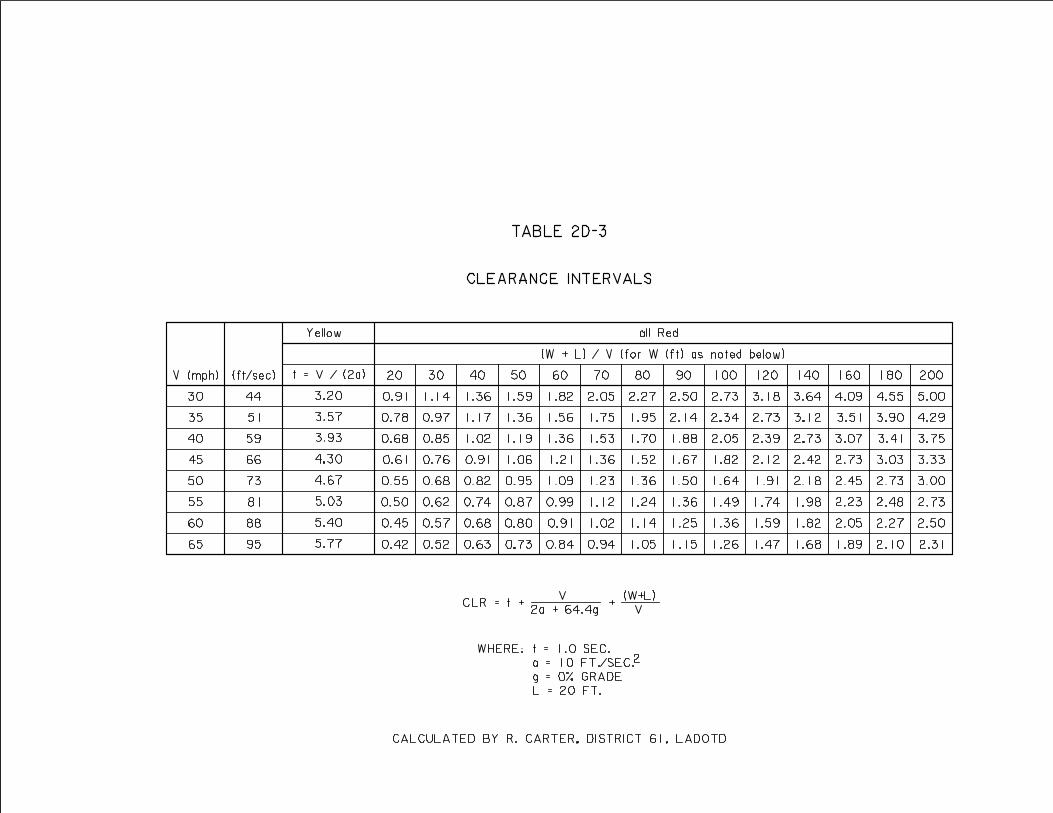
E. SIGNAL INTERCONNECT/COORDINATION – Signal Coordination occurs when a fixed timing relationship is established between two or more adjacent signals. The purpose of the coordination is to allow traffic on the coordinated street to get a green signal at all the coordinated intersections while traveling at a reasonable speed.
1.0 Warrant – Signals that are within 0.5 miles of one another should be coordinated.48
2.0 Offset/Bandwidth Calculation Methods – The following methods of calculating
signal offsets and bandwidths are preferred:
2.1 TSPP Draft – Traffic Signal Progression Program, Drafting software – a manual bandwidth optimization program.
2.2 PASSER II software – An automatic bandwidth optimization program
2.3 TEAPAC/NO STOP – An automatic bandwidth optimization program
3.0 Methods of Coordination
3.1 Hard Wire – A 7 conductor wire is run between controllers at adjacent intersections to be used for coordination purposes.
3.2 Data Communications Cable – A data communications cable, single/multi-
mode fiber optic cable (6/6) or a 6 conductor (twisted pair) cable is run between controllers at adjacent intersections to be used for coordination and communication purposes.
3.3 Time-Based (Wireless) – Coordination is accomplished internally in each
coordinated controller with timing referenced to a system time base. The internal clock in each controller must be set precisely (to the second) with the clocks in the adjacent coordinated controllers.
4.0 Installation – Generally underground rather than overhead installation is preferred.
The choice however may be determined by local preference or the location of existing interconnect lines.
4.1 Isolation – Interconnect cable is usually run in its own conduit and junction
boxes, separate from signal/detector cables. 4.2 Underground depth – 36 inches (minimum)
4.3 Conduit – 2 inch diameter PEC conduit
4.4 Junction boxes:
48 MUTCD, Millennium Edition, 2001, Part 4, p. 4D - 21
2E-1
4.4.1 Type:
LA DOTD Type “E” for 6 pair cable LA DOTD Type “G” for fiber optics cable
4.4.2 Spacing – 300 ft. (maximum) with 6 ft. of spare interconnect cable
in each junction box.
4.5 Risers – When transitioning from overhead to underground or vice versa on a utility pole, a 2 inch diameter riser must be specified for the interconnect cable.
2E-2
F. RAILROAD PRE-EMPTION – Railroad pre-emption of a traffic signal is the transfer from normal operation of the traffic signal to a special control mode that may include special signing, phasing, indications, and timing. Pre-emption is actuated upon the detection of a train and is designed to prohibit movement across the tracks, and if necessary to clear traffic off the railroad tracks prior to the arrival of the train at the crossing. Current solid state controllers come with built in preemption sequence features. 1.0 Warrant – The coordination of the operation of a traffic signal with a nearby railroad grade crossing equipped with flashing lights may be justified under the following conditions.49
1.1 Where the at grade crossing is located within 200 feet of the traffic signal, preemption should be used. At a minimum preemption shall include prohibiting movement across the tracks with blank out signs and/or special phasing. Observations shall be made to determine the length of queues and if necessary, the time required to clear the track. Such observations may be verified with calculations.
1.2 Where the at grade crossing is located more than 200 feet from the signal but
traffic from the signal is observed to back up across the railroad tracks, preemption should be used. Preemption shall include prohibiting movement across the tracks with blank out signs and/or special phasing, and timing to clear the track. Observations shall be made to determine the time required to clear the track. Such observations may be verified with calculations.
1.3 When traffic stopped for a train at the grade crossing frequently backs up into
a nearby signalized intersection, preemption may be considered.
2.0 Field Observation Method – Several computational methods are available for the estimation of queue lengths and queue clearance times for railroad preemption. The results of these calculations can vary significantly from each other and more importantly from observed values. Only observation of actual conditions can account for the numerous variables associated with roadway geometry, local driver behavior, traffic mix, etc. Accordingly, the queue lengths and queue clearance design values for preemptions shall be based on observed values. The Field Observation Procedure is given in Subsection 9.0 of this section. Computations should only be used to confirm observations of the actual track queue lengths and track clearance times which are measured directly in the field. Computations may also be necessary for future intersections or traffic conditions which do not presently exist.
3.0 Queue Length Calculations – Calculation of the traffic back up is determined with
approximately 95% certainty using Equation 2F-1 or 2F-2. The traffic back up in the through lanes as well as turn lanes should be checked.
49 Northwestern University Traffic Institute, Railroad Grade Crossing Workshop Notebook, January 1999, Section 9, p. 5-7
2F-1
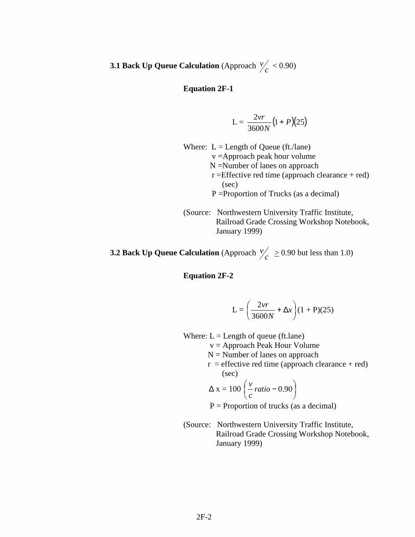
3.1 Back Up Queue Calculation (Approach c
v < 0.90)
Equation 2F-1
L = ( )( )2513600
2 PN
vr +
Where: L = Length of Queue (ft./lane) v =Approach peak hour volume N =Number of lanes on approach r =Effective red time (approach clearance + red) (sec)
P =Proportion of Trucks (as a decimal)
(Source: Northwestern University Traffic Institute, Railroad Grade Crossing Workshop Notebook, January 1999)
3.2 Back Up Queue Calculation (Approach cv > 0.90 but less than 1.0)
Equation 2F-2
L =
∆+ xN
vr3600
2 (1 + P)(25)
Where: L = Length of queue (ft.lane) v = Approach Peak Hour Volume N = Number of lanes on approach r = effective red time (approach clearance + red) (sec)
∆ x = 100
− 90.0ratiocv
P = Proportion of trucks (as a decimal) (Source: Northwestern University Traffic Institute, Railroad Grade Crossing Workshop Notebook, January 1999)
2F-2
4.0 Grade Crossing Location – Where the distance between the intersection stop line
and the rail nearest the intersection minus 6 feet (CSD = clear storage distance) (see Figure 2F-2) is greater than or equal to the longest legal truck combination allowed on Louisiana highways, the signal at the intersection in combination with the grade crossing gates and flashing lights are adequate to handle a railroad preemption sequence (see Figure 2F-1). The longest legal truck combination in Louisiana is computed to be 85 feet.
Where the clear storage distance (CSD) is less than 85 feet, the storage space warning signs, XX FEET BETWEEN TRACKS & HIGHWAY, (W10-11a) should be used in advance of the highway-rail crossing.
5.0 Pre-emption Sequence – The preemption sequencing of a two phase signal is shown
in Figure 2F-1. As shown the basic phases of the sequence are, a right-of-way change interval, a clear track interval and preemption hold phasing (while the train is occupying the crossing).
6.0 Railroad Preemption Warning Timing – The basic timing parameters for railroad
pre-emption warning time can be found in Table 2F-1. The actual warning time to be provided is the larger of either the “Traffic Signal Maximum Preemption Time” (right of way transfer + clear track intervals) or the “Railroad Warning Time”. The calculation of each parameter is as follows:
6.1 Traffic Signal Maximum Preemption Time
6.1.1 Right of Way Transfer Time – This is the time necessary for the signal to cycle to the clear track phase once a train has been detected. Its timing parameters are as follows: 50
• Adjustment Time (AT) – Possible delay in the railroad
detection equipment response. This timing is a function of the railroad equipment and should be omitted from the traffic signal design.
• Traffic Signal Equipment Delay – The time delay for the
signal equipment to respond to a train detection. Use a maximum value of 1.0 seconds depending upon the equipment manufacturer. For solid state controllers this value should be omitted.
• Min. Ped. Walk and Clearance – The MUTCD, allows
this timing to be omitted during transition into preemption.
50 Seyfried, Robert K., “Timing of Traffic Signal Preemption at Intersections near Highway-Railroad Grade Crossings,” paper, August 2001
2F-3
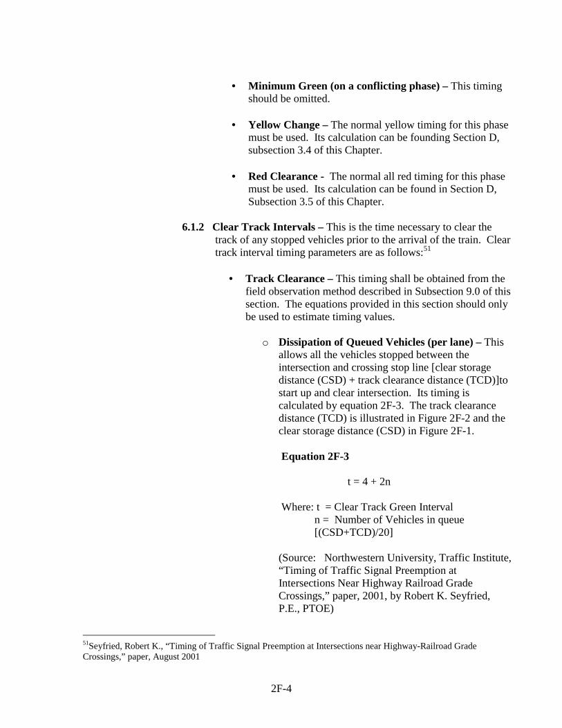
• Minimum Green (on a conflicting phase) – This timing
should be omitted.
• Yellow Change – The normal yellow timing for this phase must be used. Its calculation can be founding Section D, subsection 3.4 of this Chapter.
• Red Clearance - The normal all red timing for this phase
must be used. Its calculation can be found in Section D, Subsection 3.5 of this Chapter.
6.1.2 Clear Track Intervals – This is the time necessary to clear the
track of any stopped vehicles prior to the arrival of the train. Clear track interval timing parameters are as follows:51
• Track Clearance – This timing shall be obtained from the
field observation method described in Subsection 9.0 of this section. The equations provided in this section should only be used to estimate timing values.
o Dissipation of Queued Vehicles (per lane) – This
allows all the vehicles stopped between the intersection and crossing stop line [clear storage distance (CSD) + track clearance distance (TCD)]to start up and clear intersection. Its timing is calculated by equation 2F-3. The track clearance distance (TCD) is illustrated in Figure 2F-2 and the clear storage distance (CSD) in Figure 2F-1.
Equation 2F-3
t = 4 + 2n Where: t = Clear Track Green Interval
n = Number of Vehicles in queue [(CSD+TCD)/20]
(Source: Northwestern University, Traffic Institute, “Timing of Traffic Signal Preemption at Intersections Near Highway Railroad Grade Crossings,” paper, 2001, by Robert K. Seyfried, P.E., PTOE)
51Seyfried, Robert K., “Timing of Traffic Signal Preemption at Intersections near Highway-Railroad Grade Crossings,” paper, August 2001
2F-4
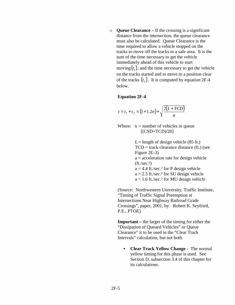
o Queue Clearance – If the crossing is a significant distance from the intersection, the queue clearance must also be calculated. Queue Clearance is the time required to allow a vehicle stopped on the tracks to move off the tracks to a safe area. It is the sum of the time necessary to get the vehicle immediately ahead of this vehicle to start moving ( )1t , and the time necessary to get the vehicle on the tracks started and to move to a position clear of the tracks ( )2t . It is computed by equation 2F-4 below.
Equation 2F-4
( ) ( )aTCDLnttt +++=+= 22.1121
Where: n = number of vehicles in queue [(CSD+TCD)/20]
L = length of design vehicle (85 ft.)
TCD = track clearance distance (ft.) (see Figure 2E-3) a = acceleration rate for design vehicle (ft./sec.²)
a = 4.4 ft./sec.² for P design vehicle a = 2.5 ft./sec.² for SU design vehicle a = 1.6 ft./sec.² for MU design vehicle
(Source: Northwestern University, Traffic Institute, “Timing of Traffic Signal Preemption at Intersections Near Highway Railroad Grade Crossings”, paper, 2001, by Robert K. Seyfried, P.E., PTOE)
Important – the larger of the timing for either the “Dissipation of Queued Vehicles” or Queue Clearance” it to be used in the “Clear Track Intervals” calculation, but not both.
• Clear Track Yellow Change - The normal
yellow timing for this phase is used. See Section D, subsection 3.4 of this chapter for its calculations.
2F-5
• Red Clearance – The normal all red timing for this phase is used. See Section D, subsection 3.5 of this chapter for its calculations.
• Separation Time – This is a safety factor to
provide additional time between the vehicle clearing the track and the arrival of the train. It typically ranges from 2 to 8 seconds. The recommended value is 2 seconds. It is important to provide when the long queues need to be cleared, train speeds are high, or there is a high percentage of trucks on the approach.
6.2 Railroad Warning Time – This is the warning time provided by the railroad
active warning system to the traffic signal controller prior to the arrival of the train. This value is a function of the railroad detection and warning equipment and shall be provided by the railroad. The method below may be used only to estimate this value. As previously mentioned, the larger of either this “Traffic Signal Maximum Preemption Time” or the “Railroad Warning Time” should be used as the actual warning time provided at a crossing. The Railroad Warning Time includes the following timing parameters:52
6.2.1 Adjustment Time (AT) – Possible delay in the railroad detection
equipment response (can be as much as 5 sec. - check with railroad).
6.2.2 Minimum Warning Time (MWT) - The MUTCD, specifies that
the flashing lights at the crossing shall operate a minimum of 20 seconds prior to the arrival of the train. The desirable range of MWT is 20 to 30 seconds.
The MUTCD also states that if the train speed of all trains using the crossing is less than 20 mph and flagging is performed by an employee on the ground, a shorter operating time can be used for the flashing lights.
6.2.3 Clearance Time (CT) – This function increases the 20 second
MWT by one second for each 10 feet or portion there of that the “Track Clearance Distance” (See Figure 2F-2) is over 35 feet. (See Equation 2F-5)
52 Seyfried, Robert K., “Timing of Traffic Signal Preemption at Intersections near Highway-Railroad Grade Crossings”, paper, August 2001
2F-6
Equation 2F-5
CT =
−10
.35 ftTCD (1 sec./ft.)
Where: CT = Clearance Time (sec) (rounded up to next whole positive second) TCD = Track Clearance Distance (ft.) (See Figure 2F-2)
6.2.4 Buffer Time (BT) - A discretionary time that provides an
additional safety factor prior to the arrival of the train. A timing of 4 to 8 seconds is generally used.
7.0 Blank Out Signs – This type sign displays a blank face unless internally illuminated
upon activation at a specific time. Such signs displaying the message/symbol “No Left Turn” or “No right Turn” are useful as part of the railroad preemption sequence at signalized intersections immediately adjacent to grade crossing. (See Figure 2F-1) At such locations, turn prohibition blank out signs would prevent traffic from turning into and occupying the limited storage area between the tracks and intersection and eventually blocking the intersection itself.
8.0 Turn Arrows – Turn phases with arrow indications which conflict with the railroad
preemption, shall be omitted until the train has cleared the railroad crossing.
9.0 Field Observation Procedure - The following queue/clearance field observation method provides a method to directly measure the saturation flow rates.53
The queue/clearance field observation procedure requires the survey of intersection geometry and the measurement of queue lengths and clearance times. The survey and measurements can be performed by a single technician; however, a two-person crew would reduce fatigue as well as possible error. The field notes and tasks identified in the following section should be adjusted according to the type of equipment used. Necessary equipment includes a measuring wheel (or tape), a stopwatch, and a Track Clearance Worksheet, Figure 2F-3.
Review existing traffic counts and select a time period during which the queue lengths are expected to reach the tracks. In order to obtain a statistically significant value, a minimum of 15 signal cycles with queues extending into the track dynamic envelope (See Figure 2F-3) are required. Queues should be checked for through lanes as well as turn lanes. For tracks that are fairly close to the intersection, queue measurements can be made at any time of day. For locations where the tracks are 200 feet or more from the tracks, queues may only extend back to the tracks during the AM, noon, or PM peaks. Notes should be made concerning the number of attempts made to observe queue lengths. If queues are expected, but do not occur
53 Highway Capacity Manual, 2000, Chapter 16, Appendix H
2F-7
after three separate attempts, track clearance will not be an issue in the preemption design at this location.
9.1 Field Measurement
9.1.1 Fill out the General Information data on the Track Clearance
Worksheet.
9.1.2 Measure and record the Geometric Input data for the site being studied.
9.1.3 Select an observation point where the track dynamic envelope and
the corresponding signal heads are clearly visible.
9.1.4 As the queue builds during the red phase, record the number and types of vehicles in the queue.
9.1.5 Note number (1st, 2nd, 3rd …) of the Nth vehicle which is stopped in
the track dynamic envelope. If no vehicle stops in the envelope, record the Nth vehicle at the end of the queue.
9.1.6 When the light turns green, start the timer. When the rear bumper
of the Nth vehicle clears the dynamic envelope, stop the timer. Record the time. If no vehicle stops on the tracks, the time should be left blank.
9.1.7 Not any unusual events that may have influenced the track
clearance time such as buses receiving or discharging passengers, stalled vehicles, unloading trucks, accidents, etc. These observations shall be discarded and not utilized in the queue length and track clearance results.
9.1.8 The design values for queue length shall be based on the maximum
observed value for a minimum of 15 cycles.
9.2 Results – If the queue is not observed to extend the tracks, then track clearance shall not be included in the preemption timing. If the queue is observed to extend to the tracks on one or more occurances, then track clearance shall be included in the preemption timing. The queue clearance value shall be the maximum observed value. If more than 5% of the queue consists of trucks (Single Unit and Tractor Trailer), then a longer separation time may be used.
2F-8
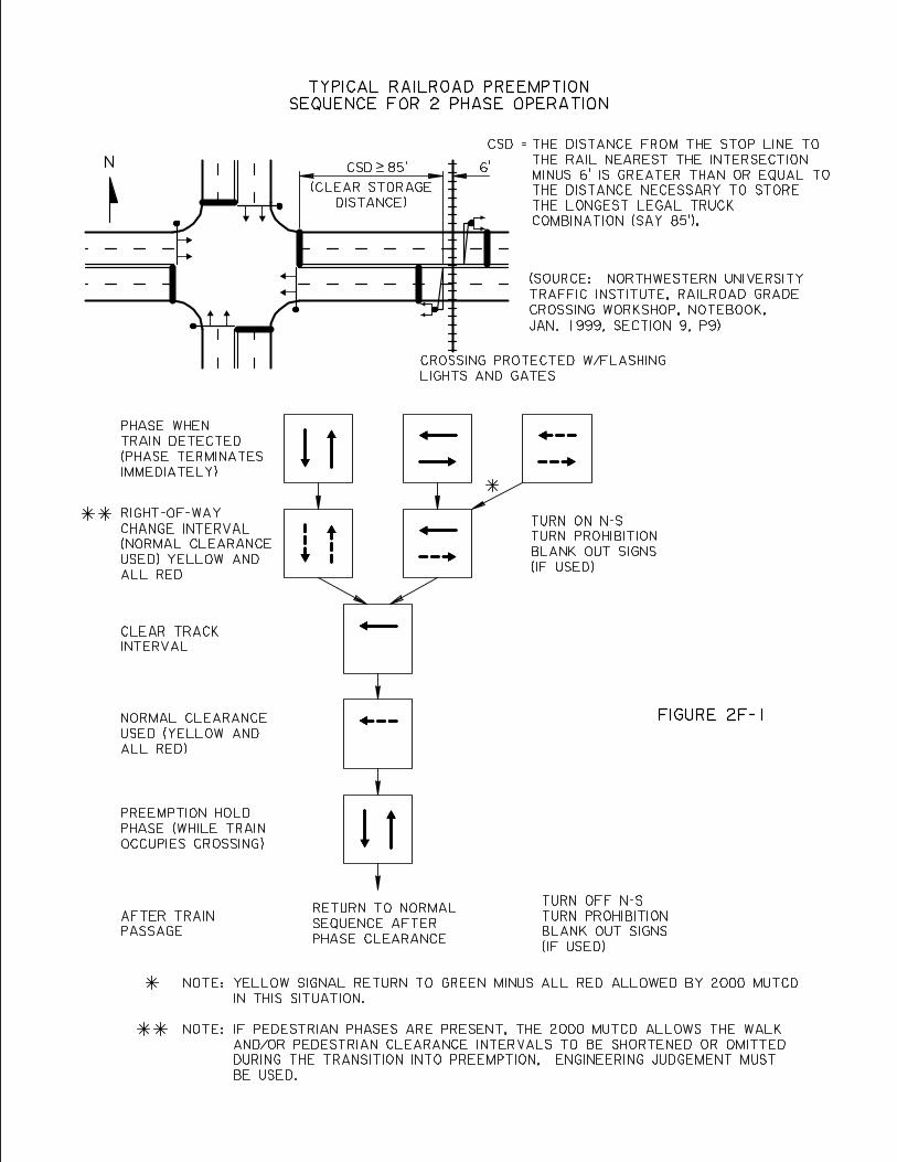
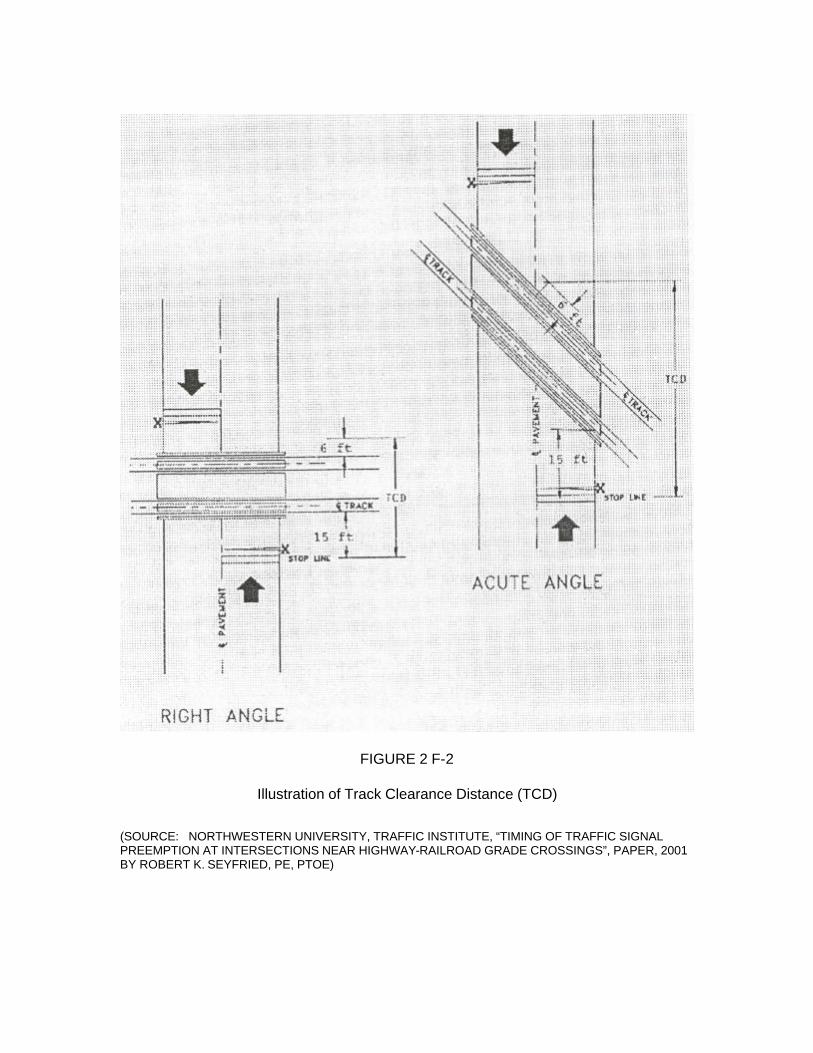
FIGURE 2 F-2
Illustration of Track Clearance Distance (TCD)
(SOURCE: NORTHWESTERN UNIVERSITY, TRAFFIC INSTITUTE, “TIMING OF TRAFFIC SIGNAL PREEMPTION AT INTERSECTIONS NEAR HIGHWAY-RAILROAD GRADE CROSSINGS”, PAPER, 2001 BY ROBERT K. SEYFRIED, PE, PTOE)
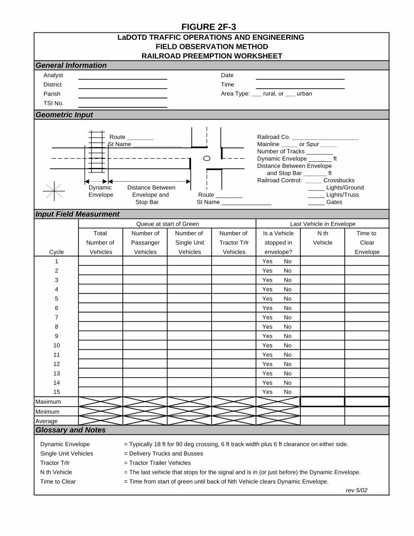
FIGURE 2F-3
General Information Analyst Date
District Time
Parish Area Type: ___ rural, or ___ urban
TSI No.
Geometric Input
Route ________ Railroad Co. ____________________St Name _______________ Mainline _____ or Spur _____
Number of Tracks ________Dynamic Envelope _______ ftDistance Between Envelope and Stop Bar _______ ftRailroad Control: _____ Crossbucks
Dynamic Distance Between _____ Lights/GroundEnvelope Envelope and Route ________ _____ Lights/Truss
Stop Bar St Name _______________ _____ Gates
Input Field MeasurmentLast Vehicle in Envelope
Total Number of Number of Number of Is a Vehicle N th Time to
Number of Passanger Single Unit Tractor Trlr stopped in Vehicle Clear
Cycle Vehicles Vehicles Vehicles Vehicles envelope? Envelope
1 Yes No
2 Yes No
3 Yes No
4 Yes No
5 Yes No
6 Yes No
7 Yes No
8 Yes No
9 Yes No
10 Yes No
11 Yes No
12 Yes No
13 Yes No
14 Yes No
15 Yes No
Maximum
Minimum
Average
Glossary and Notes
Dynamic Envelope = Typically 18 ft for 90 deg crossing, 6 ft track width plus 6 ft clearance on either side.
Single Unit Vehicles = Delivery Trucks and Busses
Tractor Trlr = Tractor Trailer Vehicles
N th Vehicle = The last vehicle that stops for the signal and is in (or just before) the Dynamic Envelope.
Time to Clear = Time from start of green until back of Nth Vehicle clears Dynamic Envelope.rev 5/02
LaDOTD TRAFFIC OPERATIONS AND ENGINEERING FIELD OBSERVATION METHOD
RAILROAD PREEMPTION WORKSHEET
Queue at start of Green
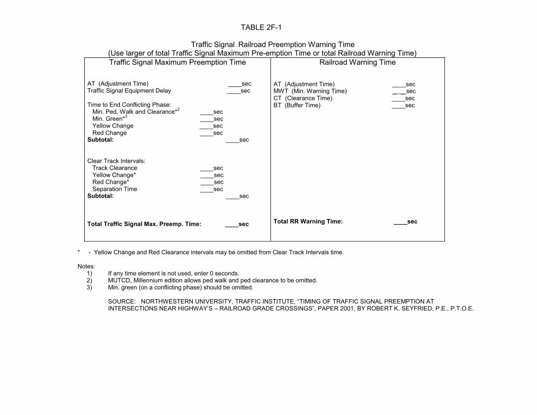
TABLE 2F-1
Traffic Signal - Railroad Preemption Warning Time (Use larger of total Traffic Signal Maximum Pre-emption Time or total Railroad Warning Time)Traffic Signal Maximum Preemption Time Railroad Warning Time
AT (Adjustment Time) ____sec Traffic Signal Equipment Delay ____sec Time to End Conflicting Phase: Min. Ped. Walk and Clearance*2 ____sec Min. Green*3 ____sec Yellow Change ____sec Red Change ____sec Subtotal: ____sec Clear Track Intervals: Track Clearance ____sec Yellow Change* ____sec Red Change* ____sec Separation Time ____sec Subtotal: ____sec Total Traffic Signal Max. Preemp. Time: ____sec
AT (Adjustment Time) ____sec MWT (Min. Warning Time) _ _ sec CT (Clearance Time) ____sec BT (Buffer Time) ____sec
Total RR Warning Time: ____sec
* - Yellow Change and Red Clearance intervals may be omitted from Clear Track Intervals time.
Notes:
1) If any time element is not used, enter 0 seconds. 2) MUTCD, Millennium edition allows ped walk and ped clearance to be omitted. 3) Min. green (on a conflicting phase) should be omitted.
SOURCE: NORTHWESTERN UNIVERSITY, TRAFFIC INSTITUTE, “TIMING OF TRAFFIC SIGNAL PREEMPTION AT INTERSECTIONS NEAR HIGHWAY’S – RAILROAD GRADE CROSSINGS”, PAPER 2001, BY ROBERT K. SEYFRIED, P.E., P.T.O.E.
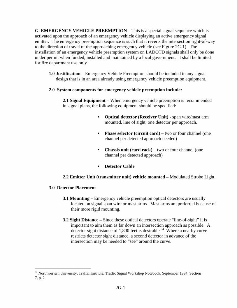
G. EMERGENCY VEHICLE PREEMPTION – This is a special signal sequence which is activated upon the approach of an emergency vehicle displaying an active emergency signal emitter. The emergency preemption sequence is such that it reverts the intersection right-of-way to the direction of travel of the approaching emergency vehicle (see Figure 2G-1). The installation of an emergency vehicle preemption system on LADOTD signals shall only be done under permit when funded, installed and maintained by a local government. It shall be limited for fire department use only. 1.0 Justification – Emergency Vehicle Preemption should be included in any signal design that is in an area already using emergency vehicle preemption equipment. 2.0 System components for emergency vehicle preemption include:
2.1 Signal Equipment – When emergency vehicle preemption is recommended in signal plans, the following equipment should be specified:
• Optical detector (Receiver Unit) - span wire/mast arm
mounted, line of sight, one detector per approach. • Phase selector (circuit card) – two or four channel (one
channel per detected approach needed)
• Chassis unit (card rack) – two or four channel (one channel per detected approach)
• Detector Cable
2.2 Emitter Unit (transmitter unit) vehicle mounted – Modulated Strobe Light.
3.0 Detector Placement
3.1 Mounting – Emergency vehicle preemption optical detectors are usually located on signal span wire or mast arms. Mast arms are preferred because of their more rigid mounting.
3.2 Sight Distance – Since these optical detectors operate “line-of-sight” it is
important to aim them as far down an intersection approach as possible. A detector sight distance of 1,800 feet is desirable.54 Where a nearby curve restricts detector sight distance, a second detector in advance of the intersection may be needed to “see” around the curve.
54 Northwestern University, Traffic Institute, Traffic Signal Workshop Notebook, September 1994, Section 7, p. 2
2G-1
3.3 Fire Station Locations
3.3.1 Signalized Entrances – Where traffic signals are located at
a fire station entrance, an optical detector can be aimed into the truck bays from across the street to activate the emergency preemption sequence.
3.3.2 Unsignalized Entrances – At such locations where traffic
from a nearby traffic signal frequently backs up in front of a fire station, an optical detector aimed into at the fire station’s truck bays can be used to activate the emergency preemption sequence at the intersection to move the traffic blocking the fire station.
2G-2
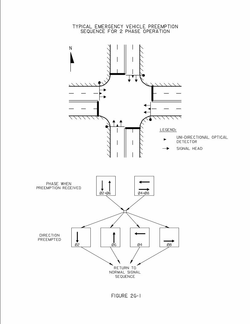

H. PEDESTRIAN SIGNAL PHASE - This is a special signal sequence actuated by pedestrian push buttons to allow pedestrians to safely cross a street. Based on engineering judgment, the pedestrian signal phase may or may not have pedestrian signal heads.
1.0 Warrants – A pedestrian signal phase with pedestrian signal heads shall be installed when any of the following occur:55
1.1 When Signal Warrant 4, “Pedestrian Volume” is fulfilled.
1.2 When Signal Warrant 5, “School Crossing” is fulfilled.
1.3 Where there is an established school crossing at the proposed signal location.
1.4 Where pedestrians are present and multiphase signal operations (lead-lag
left turns, split phasing, etc.) are used that could confuse the pedestrians.
2.0 Sequence 2.1 Concurrent Movement – The most commonly used sequence is to move
pedestrians concurrent with parallel vehicular traffic. Care must be taken however not to move pedestrians during the display of a conflicting left turn or right turn arrow for the parallel vehicular traffic.
2.2 Exclusive Movement – This sequence moves pedestrians on a phase totally
separate from any vehicular phase. When used, pedestrians cross all approaches simultaneously. This sequence should only be used where both pedestrian volumes and conflicting vehicular turning movement volumes are high.56
3.0 Timing
3.1 Walk – Where pedestrian phases are provided, walk timing provides the time necessary for a pedestrian to leave the curb to cross the street. Its minimum setting ranges from 4 to 7 seconds.57 Where large groups of pedestrian cross, field observation should be used to see how long it takes the group to leave the curb.
3.2 Pedestrian Clearance (“Flashing” Don’t Walk) - Where pedestrian phases
are provided, the pedestrian clearance provides the time necessary for a pedestrian to cross the street from the curb line to the center of the farthest travel lane or to a median of sufficient width for pedestrians to wait. A
55 MUTCD, Millennium Edition, 2001, Part 4, p. 4E - 2 56 Traffic Engineering Handbook, 1999, p. 470 57 MTUCD, Millennium Edition, 2001, Part 4, p. 4E - 13
2H-1
walking speed of 4 feet per second is assumed. It is calculated using equation 2D-3 shown below from Section D, subsection 2.3 of this chapter.
PED CLR = PV
W
Where: PED CLR = Pedestrian Clearance (sec.) W = width of the street (curb line to center of farthest lane or to the median)(ft.)
PV = pedestrian walking speed (4ft./sec.)
A portion of the pedestrian clearance interval can be timed simultaneously with the yellow and all red intervals of the concurrent vehicular phase.
3.3 Signals without Pedestrian Actuation – Where pedestrians are a consideration but pedestrian signals and push buttons are not provided, the minimum green for the concurrent parallel vehicular movement, must be at least equal to the sum of the calculated walk and pedestrian clearance for that crossing.
4.0 Pedestrian Push Buttons
4.1 Undivided Roadways – When pedestrian actuated phases are provided, pedestrians push buttons are to be provided on the appropriate corners with a push button for each crossing direction. Each push button is to be supplemented by sign R10-3a or R10-4a (See Figure 2H-1) as appropriate with an arrow pointing in the direction of the crossing. As defined in the MUTCD sign R10-3a is used where pedestrians are to cross using a green signal indication and sign R10-4a is used where pedestrians are to cross using a “Walk” signal indication.
4.2 Divided Roadways – On divided roadways both pedestrian push buttons and
signals are also to be installed in the median area if the median is of sufficient width to safely store pedestrians, and if the amount of pedestrian clearance time provided is only sufficient to reach the median area. The median push button is to be supplemental with sign R10-4a with a double headed arrow.58
4.3 Semi-Actuated Locations – At locations that have detectors only on the
minor street and pedestrians crossing the major street are a concern, pedestrian push buttons will be needed along with an adequate side street minimum green to assure a safe crossing of the major street.
58 MUTCD, Millennium Edition, 2001, Part 4, p. 4E - 9
2H-2
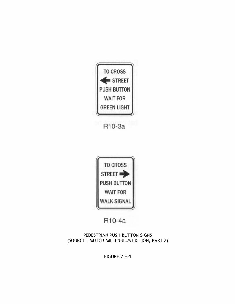
PEDESTRIAN PUSH BUTTON SIGNS (SOURCE: MUTCD MILLENNIUM EDITION, PART 2)
FIGURE 2 H-1
I. SIGNS – Traffic control signs at or in advance of signalized intersections shall be installed as follows:
1.0 Spanwire/Mast Arm Mounted – Typical spanwire and mast arm mounted sign
arrangements are shown for four way intersections in Figure 2I-1 through 2I-11 and for “T” intersections in Figures 2I-12 through 2I-15. These figures do not cover every situation, but only the more commonly occurring situations. Where overhead signs are installed they shall have a minimum of 17.5 feet vertical clearance over the roadway.
1.1 Left Turn Signal Signs (R10-10, R10-12)
1.1.1 “Left Turn Signal” Sign (R10-10) - This sign is normally installed with a protected only left turn, adjacent and to the left of the left turn signal head as shown in Figures 2I-5, 2I-8 and 2I-11. Additionally this sign is installed to the left of each left turn signal in a dual left turn situation as shown in Figure 2I-10.
1.1.2 “Left Turn Yield on Green” Signs (R10-12) – This sign is
normally installed with a protected – permitted left turn adjacent and to the left of the left turn signal head as shown in Figures 2I-3, 2I-4, 2I-6, 2I-7, and 2I-9.
1.2 Lane Control Signs (Signs R3-5 thru R3-6a) – Lane control signs should be
installed over the lanes to which they apply as follows:
1.2.1 Double Turn Lanes – Where double turning movements are specified from two lanes. (See Figures 2I-10 and 2I-15).
1.2.2 Shared Lanes - For two or more movements from a specific lane
where a movement, not normally allowed, is permitted (Sign R3-6a) (See Figure 2I-14).
1.2.3 T – Intersections – When the stem of the “T” at a “T” type
intersection is a multi-lane approach, all lane movement should be designated. (See Figure 2I-13 thru 2I-15)
1.3 Turn Prohibition Signs (Signs R3-1, R3-2, R3-4, R10-5, R10-11a)
1.3.1 No Right Turn (pictorial) Sign (R3-1) - Where needed, it should be installed to the right of the right most signal head on the approach. Typical applications are as follows:
• Diamond Interchanges - At signalized diamond
interchanges where the off ramp intersects from the right.
2I-1
• One Way Streets - At the signalized intersection of a one way side street where the one way operation is from right to left.
1.3.2 No Left Turn (pictorial) signs (R3-2) – Where needed, it should
be installed to the left of the left most signal head on the approach. Typical applications are as follows:
• Diamond Interchanges - At a signalized diamond
interchange where the off ramp intersects from the left. • One Way Streets - At the signalized intersection of a one
way side street where the direction of one way operation is from left to right.
1.3.3 No U Turn (pictorial) Sign (R3-4) – Where needed, this sign
should be ground mounted or bracket mounted to a signal pole in a median area. Where medians are not present, the sign may be installed overhead to the left of the left most signal head on the approach. Typical applications are as follows:
• Conflict - Where the U turn movement conflicts with an
overlapping side street right turn movement protected by a right turn arrow.
• Accidents - Where there is more than three accidents in a
twelve month period involving U Turning vehicles and side street right turning traffic.
• Limited Area - Where there is insufficient room to make a
U – Turn.
1.3.4 “Right On Green Arrow Only” Sign (R10-5R) – Where needed, it should be installed adjacent and to the right of the right turn signal head (see figure 2I-13). It is used where it is unsafe to turn right except when protected by the green arrow display.
1.3.5 “No Turn on Red” (R10-11a) - Where needed it is installed to the
right of the right most signal head. (See Figure 2I-1 thru 2I-7, 2I-10 thru 2I-15). Typical application are as follows:
• Sight Distance - Where sight distance to the left is
insufficient. • Service Roads - Where there is an adjacent parallel service
road to the right.
2I-2
• Pedestrian Phase - Where there is an exclusive pedestrian
signal phase.
• Accidents - Where there are 3 or more right turns on red accidents in a 12 month period.
• Dual Left Turn - When facing an opposing dual left turn.
1.4 Street Name Signs (D3) – Where used, street name signs should be placed on
diagonally opposite corners and be on the far right side with respect to motorists on the major street. They shall have white letters on a green background.59
• Strain poles/mast arm poles – Where used, street name signs are
typically bracket mounted to strain poles or mast arm poles. The letter size for these signs are 6” for upper case and 4 ¾” for lower case letters.
• Mast Arms – To optimize visibility, street name signs can be installed
overhead on mast arms when space is available. The letter size for these signs are 8” for upper case and 6 ¾” for lower case letters.
• Spanwire – Street name signs are not allowed on signal spanwires.
• Advance Street Name Sign (W16-8) – A supplemental street name
sign may be installed directly under a Signal Ahead Warning Sign (W3-3). If so mounted, the street name sign will have black letters on a yellow background.60
1.5 Blank Out Signs – These are internally illuminated signs that are blanked out
(show no message) when not illuminated. They are typically used when a turn prohibition is in effect only at certain times of the day. An application of blank out signs is where a signal has a railroad pre emption sequence and left and right turns towards the tracks are prohibited once an approaching train is detected. In this turn prohibition application they would be located to the right of the right most signal if the right turn is prohibited, and to the left of the left turn signal if the left turn is prohibited.
2.0 Ground Mounted Signs – Ground mounted signs to be used at or in advance of
signalized intersections are as follows:
59 MUTCD, Millennium Edition, 2001, Part 2, p. 2D - 31 60 MUTCD, Millennium Edition, 2001, Part 2, p. 2D - 31
2I-3
2.1 “T” – Treatment” – Where engineering judgment indicates that a signalized T – intersection needs additional warning as to the intersection geometry, the “T – Treatment” signing shown in Figure 2I-16 should be installed. Conditions possibly justifying such an installation include but are not limited to:
• Speed - High speed, rural intersections • Lighting - Poorly lit intersections
• Hazards - Intersections with hazards such as canals or bayous at the
top of the “T”.
2.2 Turn Lane Supplemental Signing – Where separate turn lanes exist that are in excess of 200 ft. in length and where turning movement traffic frequently fills these lanes to capacity, the R3-7 signs, “Left (Right) Lane Must Turn Left (Right)” should be installed at the beginning of the turn lane. These signs are intended to supplement the mandatory movement lane control overhead sign at the intersection.
2.3 Signal Ahead Sign (W3-3) – The installation of this sign is appropriate under
the following conditions:
• Signal Visibility – Where visibility of the traffic signal on any approach is less than the distances shown in Table 2I-1. An advance signal ahead sign (W3-3) shall be installed on the approach at a distance back from the intersection shown in Table 2I-2.
• Speed - On high speed rural approaches, approaching the first signal in an
urbanized area the W3-3 may be justified.
• In other situations where engineering judgment reveals the need for the Signal Ahead Sign.
2.4 Street Name Signs (D3) – Street name signs installed on their own post are
the responsibility of the local community or parish.
3.0 Sign Size – Traffic control signs use at LA DOTD signalized intersections shall be of the size specified in the MUTCD. The unit measurement for these signs as shown in signal plans shall be in square feet of sign face. Table 2I-3 gives the areas of the most common sign sizes.
4.0 Internally Illuminated Signs – Internally illuminated signs are generally not used at
LA DOTD signalized intersections. Where used they shall include only traffic control signs that are mast arm mounted.
2I-4
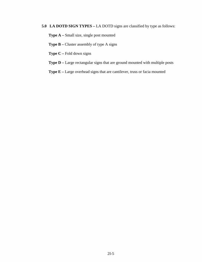
5.0 LA DOTD SIGN TYPES – LA DOTD signs are classified by type as follows:
Type A – Small size, single post mounted Type B – Cluster assembly of type A signs Type C – Fold down signs Type D – Large rectangular signs that are ground mounted with multiple posts Type E – Large overhead signs that are cantilever, truss or facia mounted
2I-5
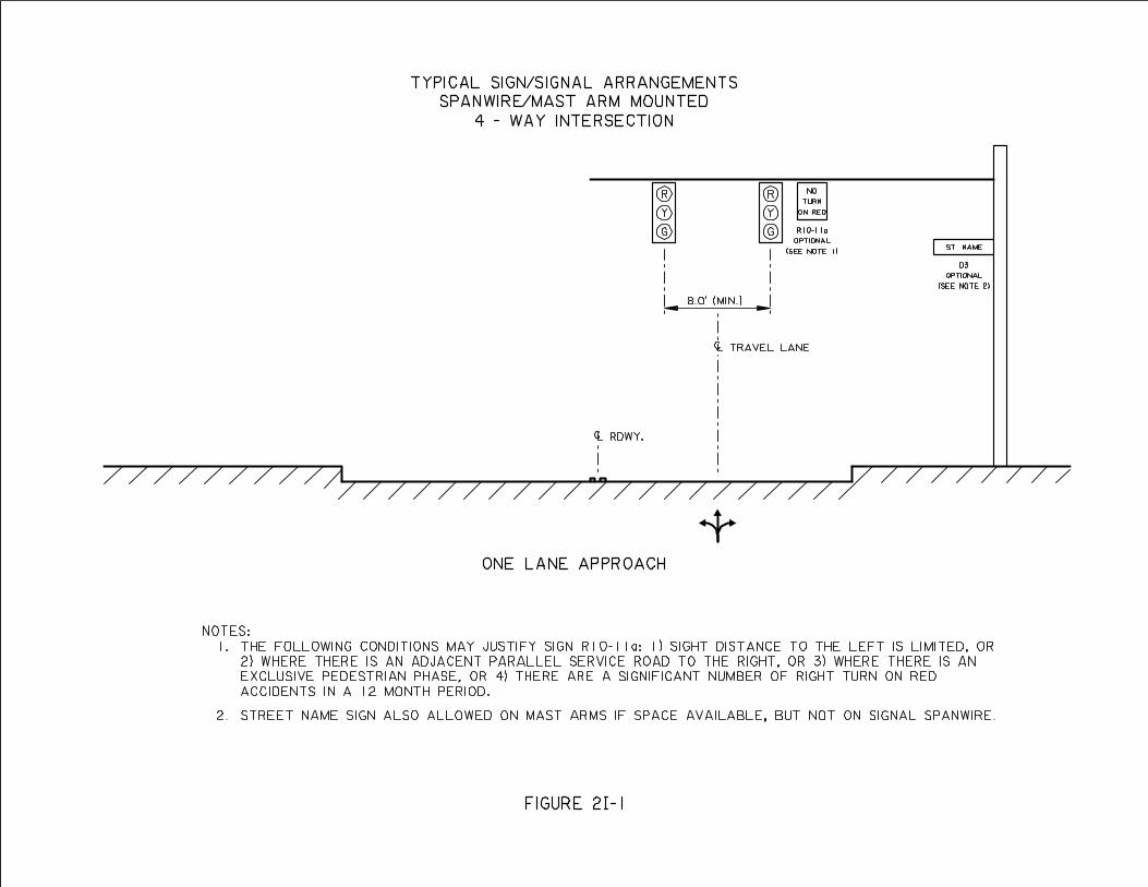
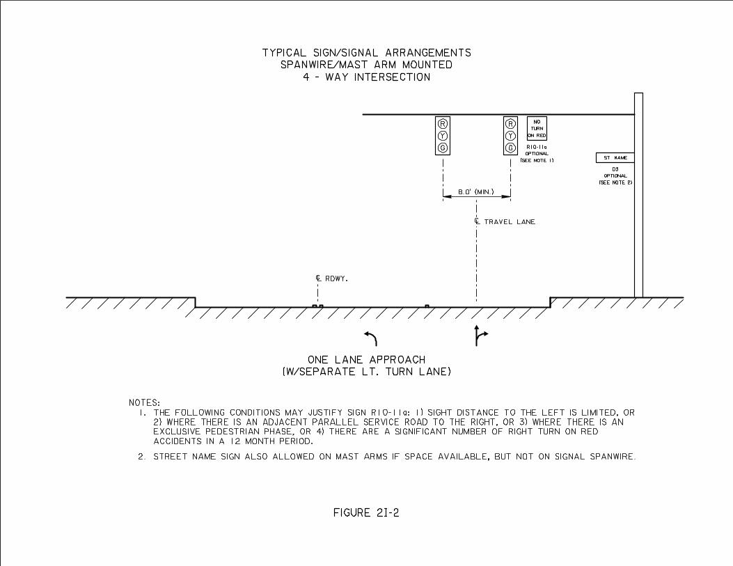
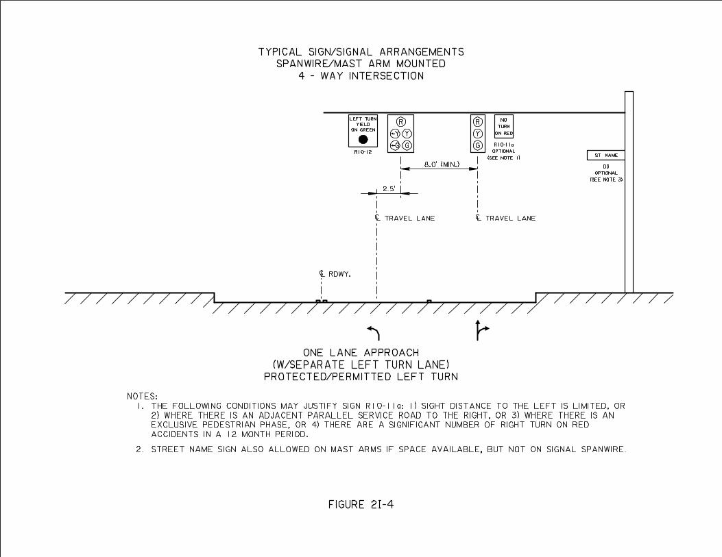
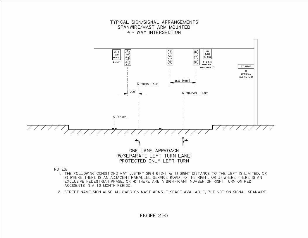
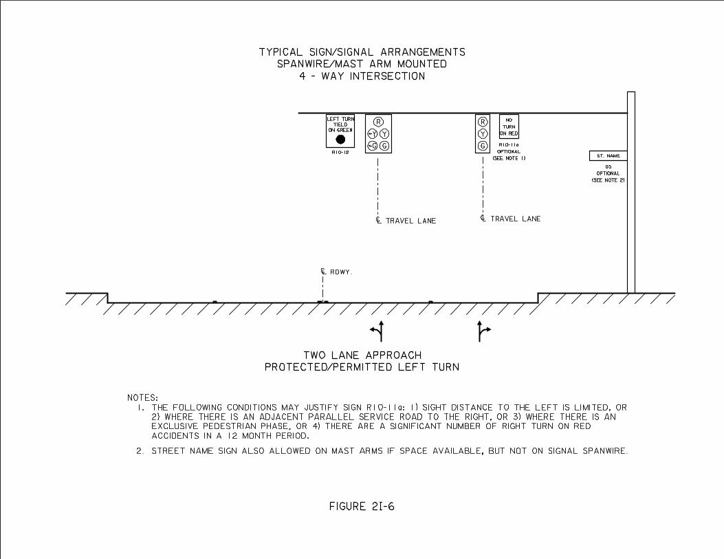
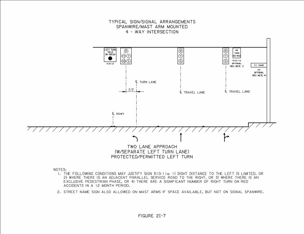
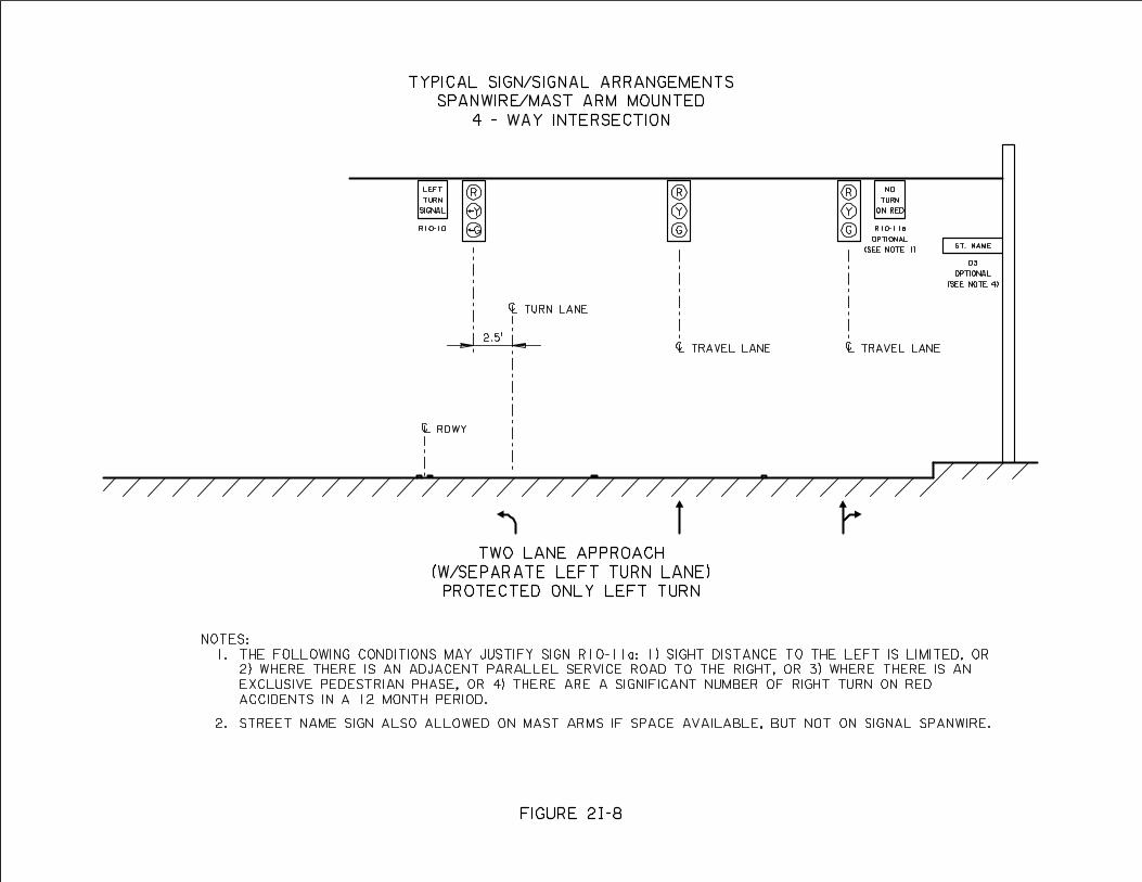
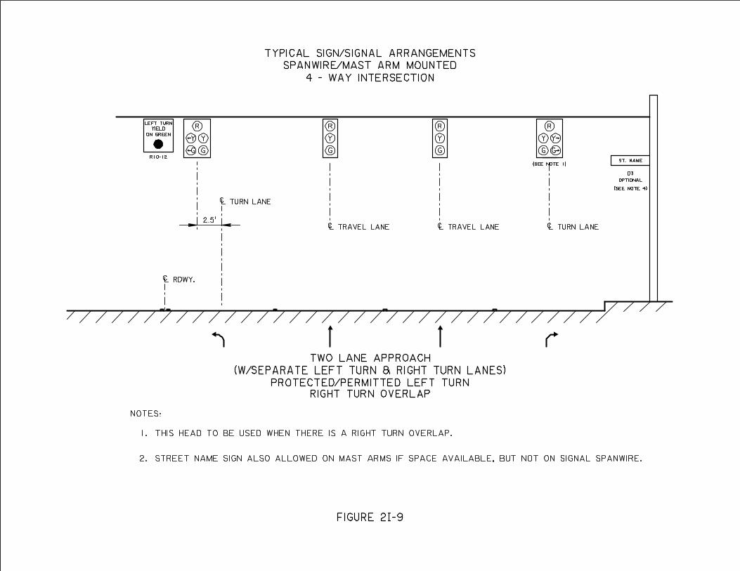
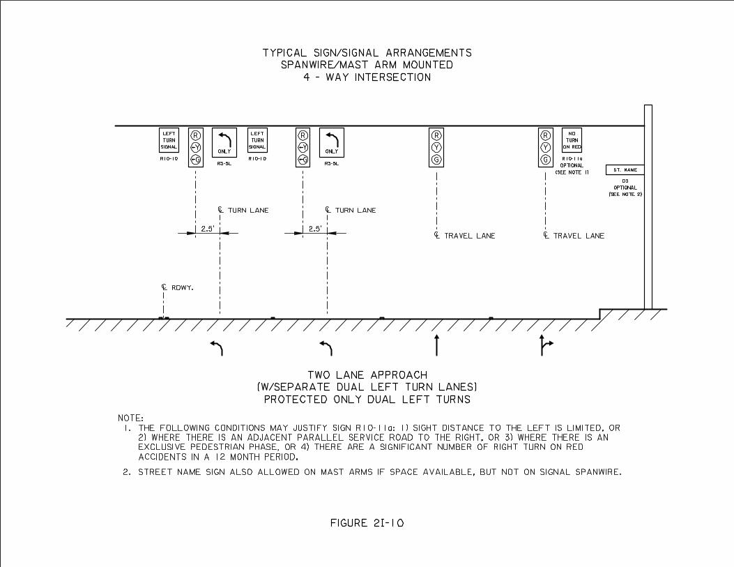
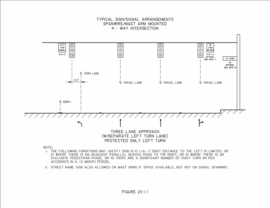
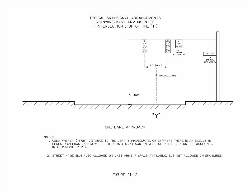
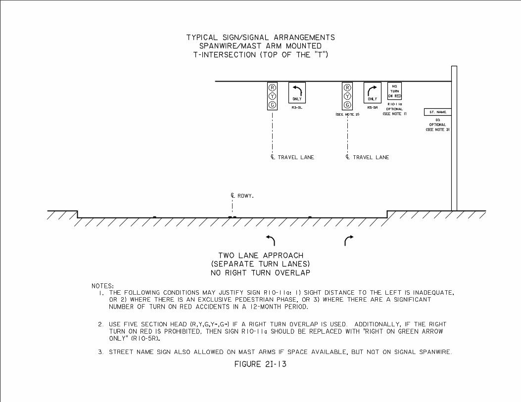
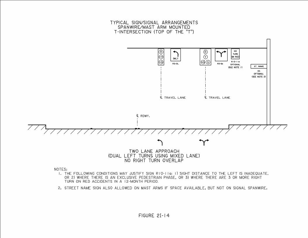
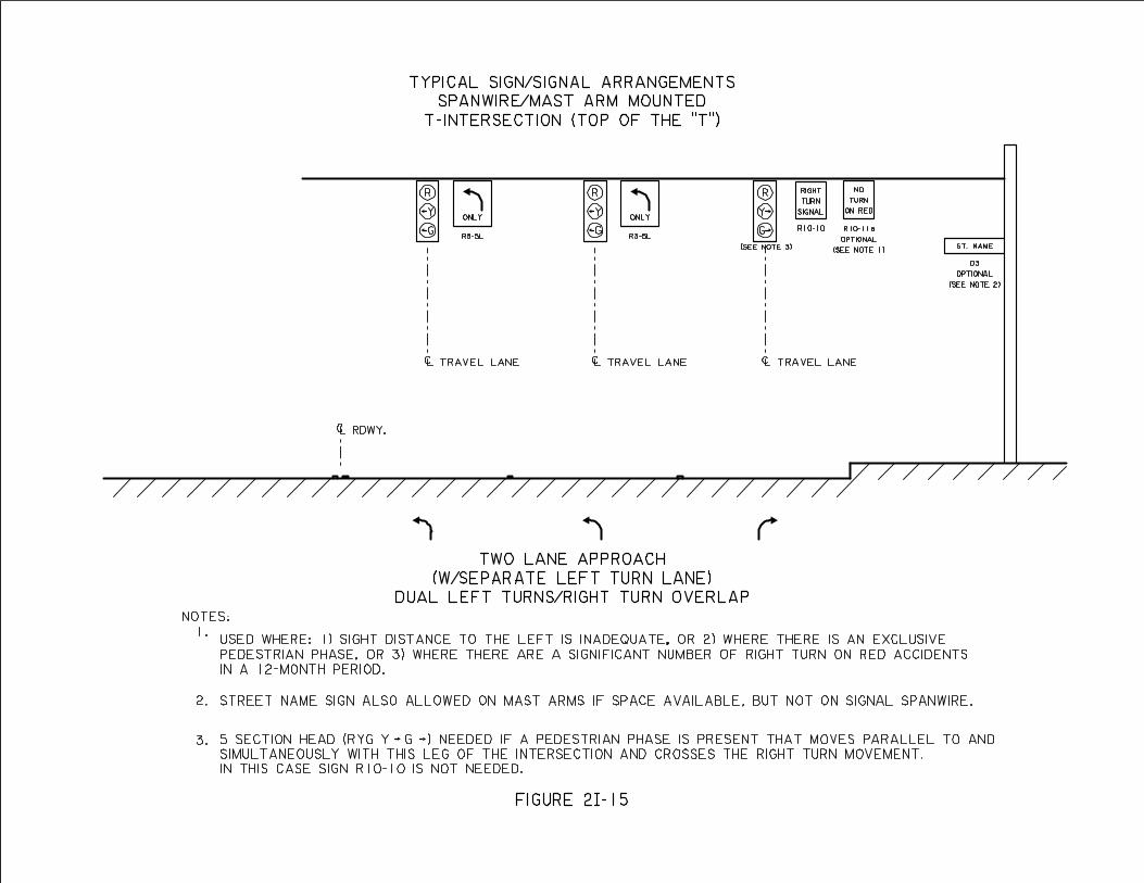
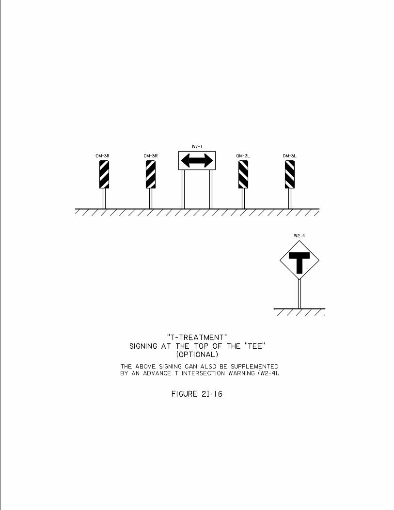
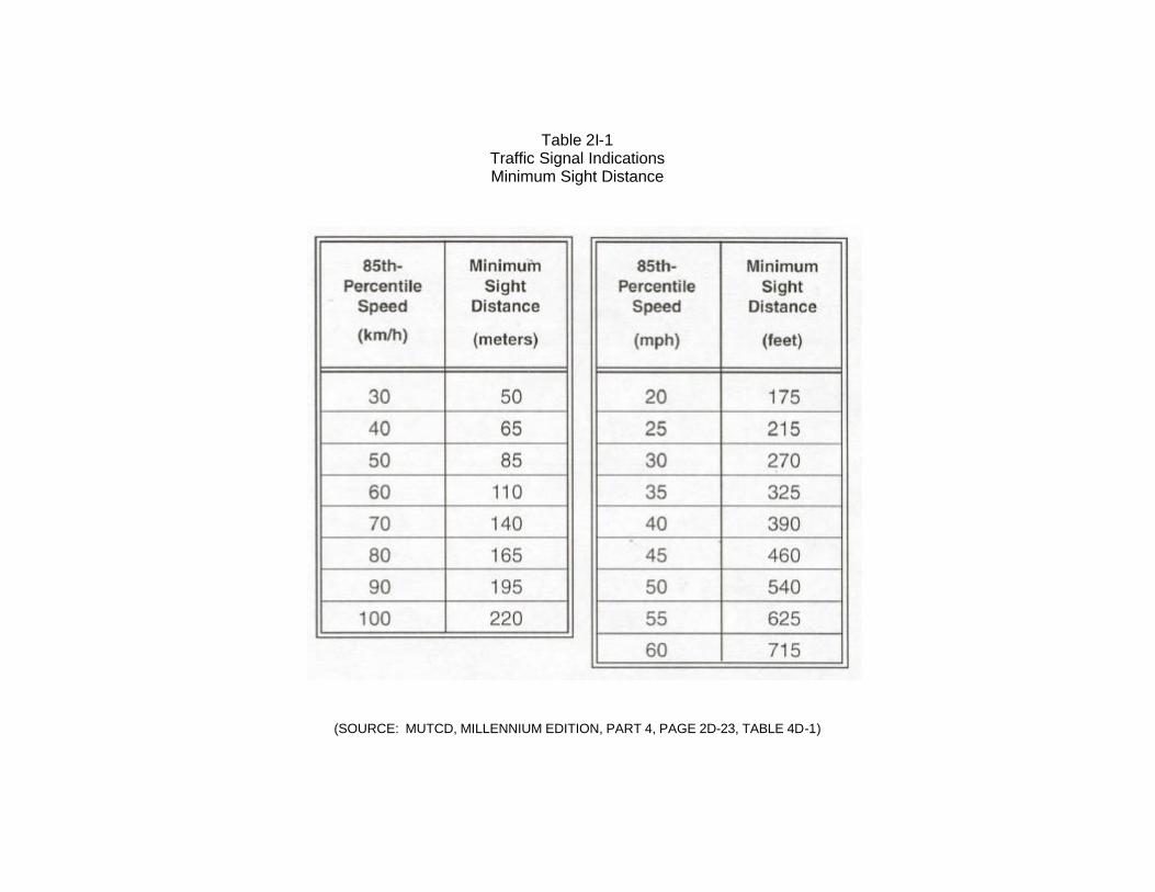
Table 2I-1 Traffic Signal Indications Minimum Sight Distance
(SOURCE: MUTCD, MILLENNIUM EDITION, PART 4, PAGE 2D-23, TABLE 4D-1)
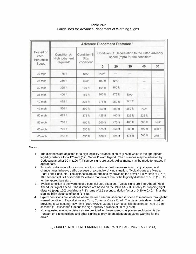
Table 2I-2 Guidelines for Advance Placement of Warning Signs
Notes:
1. The distances are adjusted for a sign legibility distance of 50 m (175 ft) which is the appropriate legibility distance for a 125 mm (5 in) Series D word legend. The distances may be adjusted by Deducting another 30 m (100 ft) if symbol signs are used. Adjustments may be made for grades if appropriate.
2. Typical conditions are locations where the road user must use extra time to adjust speed and change lanes in heavy traffic because of a complex driving situation. Typical signs are Merge, Right Lane Ends, etc. The distances are determined by providing the driver a PIEV time of 6.7 to 10.0 seconds plus 4.5 seconds for vehicle maneuvers minus the legibility distance of 50 m (175 ft) for the appropriate sign.
3. Typical condition is the warning of a potential stop situation. Typical signs are Stop Ahead, Yield Ahead, or Signal Ahead. The distances are based on the 1990 AASHTO Policy for stopping sight distance (page 120) providing a PIEV time of 2.5 seconds, friction factor of 0.30 to 0.40, minus the sign legibility distance of 50 m (175 ft).
4. Typical conditions are locations where the road user must decrease speed to maneuver through the warned condition. Typical signs are Turn, Curve, or Cross Road. The distance is determined by providing a 1.6 second PIEV time (1990 AASHTO, page 119), a vehicle deceleration rate of 3 m/ second2 (10 ft/second2 ), minus the sign legibility distance of 50 m (175 ft).
5. No suggested minimum distances are provided for these speeds, as placement location is de- Pendant on site conditions and other signing to provide an adequate advance warning for the driver.
(SOURCE: MUTCD, MILENNIUM EDITION, PART 2, PAGE 2C-7, TABLE 2C-4)
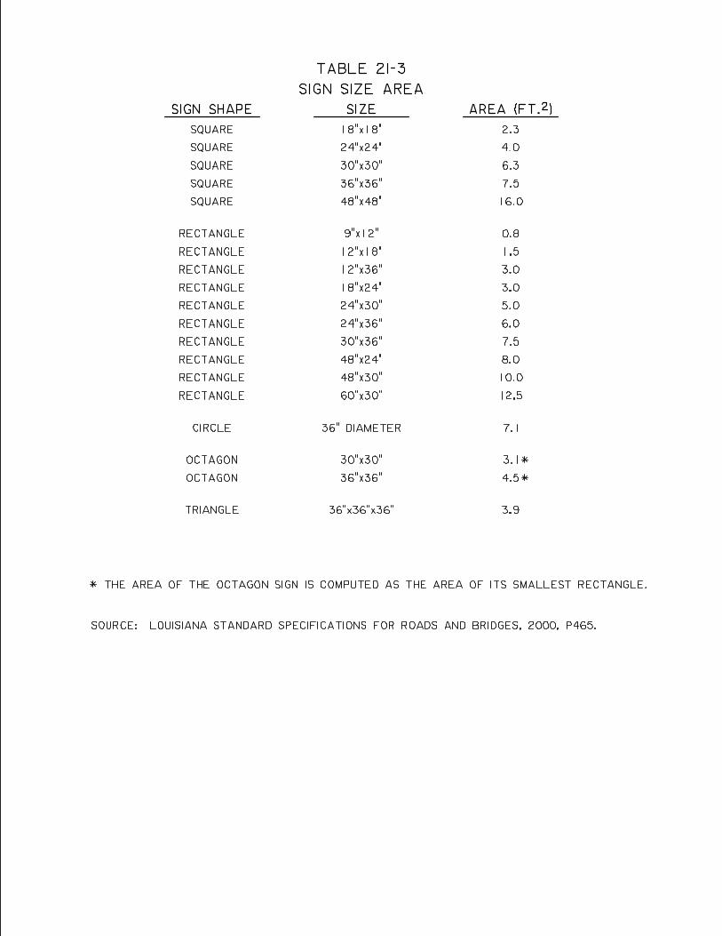
J. SIGNAL HEADS – Signal heads shall adhere to those standards set forth in the MUTCD. The LA DOTD application of those standards is as follows:
1.0 Lens Size – Twelve (12) inch diameter lenses are required on all LA DOTD signal heads regardless of their distance beyond the stop line.
2.0 Housing Color – Signal head housing shall be specified in LA DOTD EDSM
IV.7.1.8.
3.0 Back plates – Signal back plates increase the contrast between the signal indications and the signal background. Things in the signal background that could cause signal visibility problems are a rising or setting sun or intensive advertising signing. Back plates are not normally installed on LA DOTD signals unless it can be demonstrated that an actual signal visibility problem exists and the signals are mast arm mounted. Where used, back plates shall have a dull black finish.
4.0 Number of Signal Faces61
4.1 Major Movement – A minimum of two signal faces is to be provided for the
major movement on each approach, even if the major movement is a turning movement. This provides a safety factor should an indication burn out in one of the two faces.
4.2 Supplemental Face – If the signal faces provided as required is paragraph 4.1
above are more than 150 ft. beyond the stop line, a supplemental near side signal face is required.
4.3 Dual Left Turns – Where dual separate left turn lanes are provided, a
separate left turn face shall be provided for each lane (see typical explanation Figures 2I-10 and 2I-15).
5.0 Positioning
5.1 Relative to the Stop Line
5.1.1 Required Faces – At least one if not both of the signals faces required in paragraph 4.1 above shall be placed between 40-150 ft. from the stop line.
5.1.2 Supplemental Face – If both signal faces are more than 150 ft.
from the stop line, a supplemental near side signal face is required.
5.2 Horizontal Placement
61 MUTCD, Millennium Edition, 2001, Part 4, p. 4D – 23 to 4D - 27
2J-1
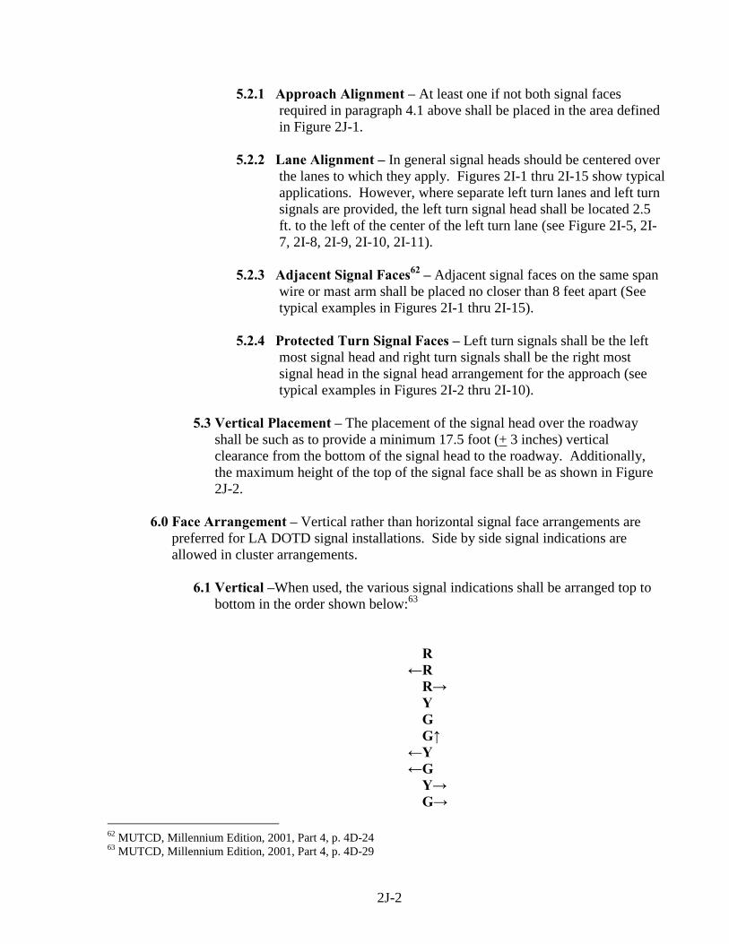
5.2.1 Approach Alignment – At least one if not both signal faces required in paragraph 4.1 above shall be placed in the area defined in Figure 2J-1.
5.2.2 Lane Alignment – In general signal heads should be centered over
the lanes to which they apply. Figures 2I-1 thru 2I-15 show typical applications. However, where separate left turn lanes and left turn signals are provided, the left turn signal head shall be located 2.5 ft. to the left of the center of the left turn lane (see Figure 2I-5, 2I-7, 2I-8, 2I-9, 2I-10, 2I-11).
5.2.3 Adjacent Signal Faces62 – Adjacent signal faces on the same span
wire or mast arm shall be placed no closer than 8 feet apart (See typical examples in Figures 2I-1 thru 2I-15).
5.2.4 Protected Turn Signal Faces – Left turn signals shall be the left
most signal head and right turn signals shall be the right most signal head in the signal head arrangement for the approach (see typical examples in Figures 2I-2 thru 2I-10).
5.3 Vertical Placement – The placement of the signal head over the roadway
shall be such as to provide a minimum 17.5 foot (+ 3 inches) vertical clearance from the bottom of the signal head to the roadway. Additionally, the maximum height of the top of the signal face shall be as shown in Figure 2J-2.
6.0 Face Arrangement – Vertical rather than horizontal signal face arrangements are
preferred for LA DOTD signal installations. Side by side signal indications are allowed in cluster arrangements.
6.1 Vertical –When used, the various signal indications shall be arranged top to
bottom in the order shown below:63 R ←R R→ Y G G↑ ←Y ←G Y→ G→
62 MUTCD, Millennium Edition, 2001, Part 4, p. 4D-24 63 MUTCD, Millennium Edition, 2001, Part 4, p. 4D-29
2J-2
6.2 Horizontal –When used, the various signal indications shall be arranged left
to right in the order shown below:64 R, ←R, R→, Y, ←←←←Y, ←←←←G, G, G↑, Y→→→→, G→→→→
7.0 Left Turn Signals
7.1 Three section heads (R, ←←←←Y, ←←←←G) – Three section left turn heads are used for a “protected only” left turn operation, and there exists a separate left turn lane. Three section left turn heads are also used where dual left turns exist and at the top of some “T” intersections. (See typical examples Figures 2I-5, 2I-8, 2I-10, 2I-11, 2I-14, 2I-15).
7.2 Four Section Heads (R, Y, ←←←←G, G) – Four section left turn heads are used
where the left turn is part of a split phase operation and also at the top of some “T” intersections.(See typical examples in Figure 2I-14).
7.3 Five Section Heads (R, Y, G, ←←←←Y, ←←←←G) – Five section left turn signal heads
are used both with and without a separate left turn lane, and where the left turn operation is “protected/permitted”. (See typical Figures 2I-3, 2I-4, 2I-6, 2I-7, 2I-9).
8.0 Right Turn Signals – Right turn signals are normally provided only where there is a
separate right turn lane accompanied by a right turn signal overlap with a compatible cross street left turn signal phase.
8.1 Three Section Heads (R, Y→→→→, G→→→→) - Three section right turn heads are at
the top of some “T” intersections (See Figure 2I-15). 8.2 Five Section Heads (R, Y, G, Y→→→→, G→→→→) –Five section right turn heads are
most commonly used at 4-way intersections (See Figure 2I-9). Where there are pedestrian movements protected by pedestrians signal indications a five section head may be used at some “T” intersections (See Figures 2I-13).
9.0 Pedestrian Signal Indications – LADOTD allows only the one section integrated
pedestrian head on new signal installations. The bottom of its housing shall be located 7-10 feet above the sidewalk.
9.1 Walking Person Symbol65
9.1.1 Meaning – Walk
64 MUTCD, Millennium Edition, 2001, Part 4, p. 4D-29 65 MUTCD, Millennium Edition, 2001, Part 4, p. 4E-1 to 4E-5
2J-3
9.1.2 Color – White 9.1.3 Size – LADOTD uses only the 9 inch high symbol.
9.1.4 Location – Integral with and to the right of the upraised hand symbol.
9.2 Upraised Hand Symbol66 9.2.1 Meaning
• Flashing – Pedestrian Clearance • Steady – Don’t Walk
9.2.2 Color - Portland Orange
9.2.3 Size – LADOTD uses only the 9 high inch symbol. 9.2.4 Location – Integral with and to the left of the walking person
symbol. 10.0 Visibilities and Shielding – As a minimum all signal indications should be
equipped with cut away (partial) visors to prevent the sun phantom effect (signal appearing to be on due to the sun reflecting on the signal indication lens).67 Additionally other installation problems may exist that would require the signal to be shielded further or to have its visibility limited. The most common problems and their possible solutions are as follows.
10.1 Left Turn Signals – Where left turn signals simultaneously display
different color indications than the adjacent through signals, either full tunnel visors with louvers or programmed visibility lenses can be used on the left turn signals.
10.2 Closely Spaced Signals – Where signals are closely spaced and
simultaneously display conflicting color indications to approaching motorists, programmed visibility lenses can be installed on the far signals.
10.3 Acute Angle Intersections – Where the intersection of two roadways is less
than 90 degrees causing conflicting signal indications on one street to be seen by motorists on the other street, either programmed visibility lenses or full tunnel visors with louvers can be used on the signals.
66 MUTCD, Millennium Edition, 2001, Part 4, p. 4E-1 to 4E-3 67 Traffic Control Devices Handbook, 1983, p. 4 - 62
2J-4
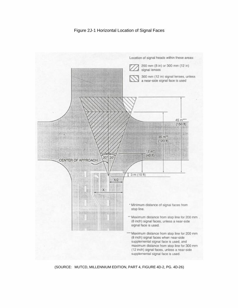
Figure 2J-1 Horizontal Location of Signal Faces
(SOURCE: MUTCD, MILLENNIUM EDITION, PART 4, FIGURE 4D-2, PG. 4D-26)
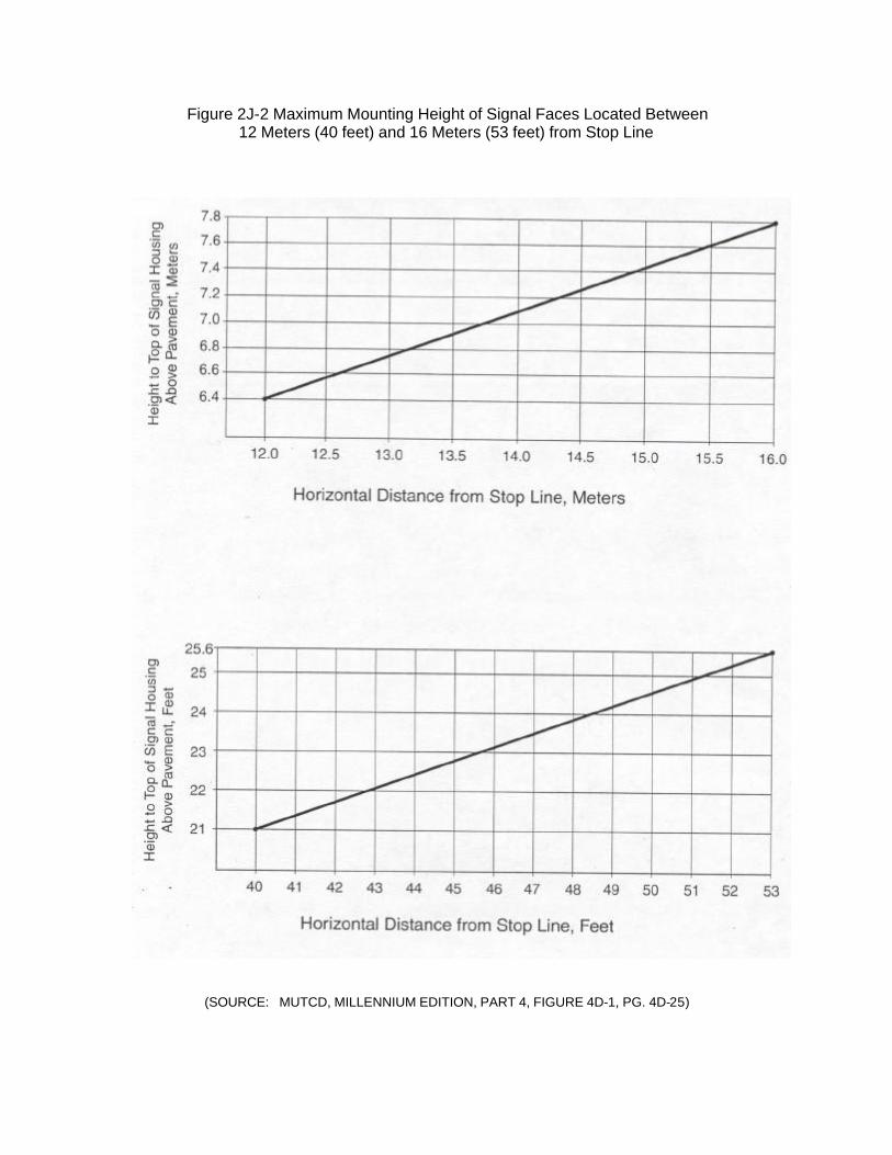
Figure 2J-2 Maximum Mounting Height of Signal Faces Located Between 12 Meters (40 feet) and 16 Meters (53 feet) from Stop Line
(SOURCE: MUTCD, MILLENNIUM EDITION, PART 4, FIGURE 4D-1, PG. 4D-25)
K. TRAFFIC SIGNAL CONTROLLERS/CABINETS
1.0 Signal Controllers – The standard controller to be used at all new signalized intersections shall be an 8-phase, NEMA controller that meets current LA DOTD standards and specifications. An 8-phase controller is to be specified even at “T” intersections to facilitate controller interchangeability and to simplify LA DOTD’s controller inventory.
2.0 Controller Cabinets
2.1 Types:
• LA DOTD Type 3 – Pole mounted cabinets
• LA DOTD Type 6 – Ground mounted cabinets. Any controller locations that are in a closed loop system shall have ground mounted cabinets.
2.2 Interconnect/Communications – Where installed in an existing system, the
type cabling shall match the existing system cabling.
2.2.1 Hard Wire – A 7 conductor cable can be run between adjacent controllers for the purpose of signal coordination through the transmission of electrical pulses.68 A hard wire relay panel is needed in the controller cabinet.
2.2.2 Data Communication Cable – A 6 pair twisted cable or fiber
optics cable can be run between adjacent controllers for the purpose of signal coordination and data transmission.69
2.2.3 Modems
• When a 6 pair twisted cable is used for signal coordination, a
modem is needed in each coordinated signal cabinet. In addition the master location in a closed loop system needs an additional dial up modem.
• When fiber optics cable is used for signal coordination, a fiber
optics interface modem is needed in each coordinated signal cabinet. In addition the master location in a closed loop system needs an additional dial up modem.
• Systems using a 7 conductor cable for signal coordination use a
hard wire relay panel instead of a modem.
68 Louisiana Standard Specifications for Roads and Bridges, 2000, Section 1020.03 69 Louisiana Standard Specifications for Roads and Bridges, 2000, Section 1020.03
2K-1
2.2.4 Telephone drops – Telephone drops are needed at all master locations in a closed loop coordinated system.
2.2.5 Master to TMC/District Office – Communications between these
two points can be as follows according to LADOTD preferences:
• Fiber Optics • Phone Drop
• Radio
2.3 Orientation – The controller cabinet shall be so oriented that the traffic
personnel will be facing the intersection while looking in the cabinet. 2.4 Service Pad – All controller installations shall be provided with a 3’ x 5’ x 4”
all weather service pad in front of the controller cabinet door to provide a standing surface for service personnel.
2.5 Location – Controller cabinets should be located as far as practical off the
edge of the roadway and in the same intersection quadrant as the power source.
2K-2
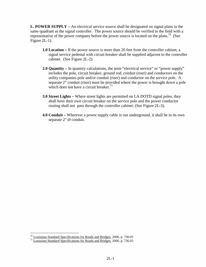
L. POWER SUPPLY – An electrical service source shall be designated on signal plans in the same quadrant as the signal controller. The power source should be verified in the field with a representative of the power company before the power source is located on the plans.70 (See Figure 2L-1).
1.0 Location – If the power source is more than 20 feet from the controller cabinet, a signal service pedestal with circuit breaker shall be supplied adjacent to the controller cabinet. (See Figure 2L-2).
2.0 Quantity – In quantity calculations, the term “electrical service” or “power supply”
includes the pole, circuit breaker, ground rod, conduit (riser) and conductors on the utility companies pole and/or conduit (riser) and conductor on the service pole. A separate 2” conduit (riser) must be provided where the power is brought down a pole which does not have a circuit breaker.71
3.0 Street Lights – Where street lights are permitted on LA DOTD signal poles, they
shall have their own circuit breaker on the service pole and the power conductor routing shall not pass through the controller cabinet. (See Figure 2L-3).
4.0 Conduit – Wherever a power supply cable is run underground, it shall be in its own
separate 2” Ø conduit.
70 Louisiana Standard Specifications for Roads and Bridges, 2000, p. 736.05 71 Louisiana Standard Specifications for Roads and Bridges, 2000, p. 736.05
2L-1
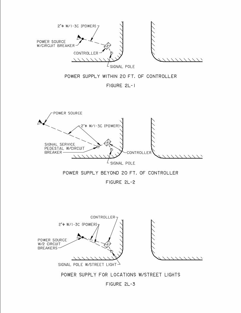
M. SIGNAL SUPPORTS – Signal supports which include both steel strain poles and mast arm poles shall be in accordance with LA DOTD specifications. Adjacent utility poles shall not be used for signal supports in new installations unless limited physical conditions preclude the installation of separate signal supports. Engineering judgment must be exercised in determining the proper signal support system for the intersection. The following guidelines are provided to aid in that determination.
1.0 Strain Poles – Strain poles may be applicable where a mast arm installation would require mast arms in excess of 50 ft. in length.
1.1 Maximum Span Length – The placement of the strain poles shall be such as
to limit the span wire length to a maximum of 150 ft. 1.2 Span Wire Arrangements – Span wire arrangements in general allow for
further pole setbacks from the roadway than do mast arms installations. In addition they eliminate the need for jacking and boring under the roadway by allowing signal and detector cables to be run overhead on the signal spanwire.72 The following are the most common span wire arrangements.
1.2.1 Box Span(See Figure 2M-1) – This signal arrangement places
strain poles on each of the four corners of the intersection. •••• Advantages:73
- Allows good alignment of signal heads and span wire mounted signs.
- Provides the required minimum 40 feet distance between the signal heads and stop line on all approaches.
- Provides lower span wire lengths, loading and sag than diagonal spans.
- Provides locations for pedestrian signals and pedestrian detectors when needed.
•••• Disadvantages:74
- Requires 4 poles - Could require supplemental signal heads if the signal heads
are beyond 150 feet beyond the approach stop line.
1.2.2 Z Spans (See Figures 2M-2, 2M-3) – Z span installation may be applicable on divided roadways where medians are at least 8 feet wide. Z spans are also applicable at offset intersections.
72 Traffic Engineering Handbook, 1999, p. 503 73 Traffic Engineering Handbook, 1999, p. 506 74 Traffic Engineering Handbook, 1999, p. 506
2M-1

• Advantages:75 - On divided roadways, shorter spanwires are required across
the street with the median. - On divided roadways, a closer placement of signal heads for
the street without the median is possible. - Provides good signal placement for offset intersections.
• Disadvantages:76 - On divided roadways, it places signal poles in median areas
where they are more likely to be struck by vehicles. - On divided roadways, additional signal poles may be
needed if pedestrian signals and detectors are required. - On divided roadways, pedestrians cannot see the parallel
signal indications once they get to the median area.
1.2.3 U-Span (See Figure 2M-4) – The arrangement has good application at T intersections.
• Advantages:
- Allows good alignment of signal heads and span wire mounted signs.
- Poles are available for pedestrian signal heads and detectors if needed.
- Good visibility of signal indicators for pedestrians. - Provides shorter span wire lengths and less loading and sag
than the diagonal spans.
• Disadvantages: - Four poles are required.
1.3 Pole Base – All LA DOTD steel strain poles shall have “shoe” type base.77 1.4 Pole Height Determination – The height of a strain pole is determined by
equation 2M-1 and Figure 2M-5 shows how the formula was derived. When providing a pole height on signal plans it is important to specify that the top of the pole foundation is to be at the same elevation as the roadway crown.
75 Traffic Engineering Handbook, 1999, p. 507 76 Traffic Engineering Handbook, 1999, p. 507 77 LA DOTD, Traffic Services and Installation Detail Standard Plans, sheet 217
2M-2
Equation 2M-1
PH = 23 + L20
Where: PH = Pole height (feet) L = Span wire length (feet) Where two spanwires attach to the same strain pole, the pole height will be determined by using the longer of the two spanwires. Pole heights shall be rounded up where necessary to be specified in even number feet (26, 28, 30, etc.).
1.5 Pole Location
1.5.1 General – Strain poles should be located as far as practical off the edge of the roadway while staying within the right-of-way and keeping the spanwire length under 150 feet. They should not be located on medians whose widths are less than 8 feet.
1.5.2 Signal Location – Strain poles should be located so that signals
hung on their spanwire are located between 40 to 150 feet from the approach stop line.
1.5.3 Minimum Clearances – On uncurbed roadways, it is desirable
that poles be located a minimum of 6 feet outside the roadway shoulder or 12 feet outside the edge of the travelway. On curbed roadways poles shall be located no closer than 2 feet to the front of curb.78 In any case, signal poles should be located as far as practical from the edge of travel lane without adversely affective signal visibility.79
1.6 Luminaires – Where street lights are permitted on LA DOTD strain poles
they are to be designed integral with the pole and mounted at a minimum height of 30 ft. above the roadway.
2.0 Mast Arms – Where used on LA DOTD signal installations, mast arms shall be in
accordance with current LA DOTD standard details.80
78 MUTCD, Millennium Edition, 2001, Part 2, p. 2A-12, 2A-22 79 MUTCD, Millennium Edition, 2001, Part 4, p. 4D-36 80 LA DOTD, Traffic Services and Installation Detail Standard Plans, sheet 217
2M-3
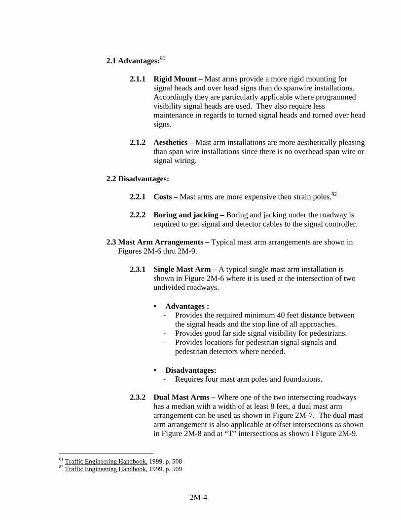
2.1 Advantages:81
2.1.1 Rigid Mount – Mast arms provide a more rigid mounting for signal heads and over head signs than do spanwire installations. Accordingly they are particularly applicable where programmed visibility signal heads are used. They also require less maintenance in regards to turned signal heads and turned over head signs.
2.1.2 Aesthetics – Mast arm installations are more aesthetically pleasing
than span wire installations since there is no overhead span wire or signal wiring.
2.2 Disadvantages:
2.2.1 Costs – Mast arms are more expensive then strain poles.82 2.2.2 Boring and jacking – Boring and jacking under the roadway is
required to get signal and detector cables to the signal controller.
2.3 Mast Arm Arrangements – Typical mast arm arrangements are shown in Figures 2M-6 thru 2M-9.
2.3.1 Single Mast Arm – A typical single mast arm installation is
shown in Figure 2M-6 where it is used at the intersection of two undivided roadways.
• Advantages :
- Provides the required minimum 40 feet distance between the signal heads and the stop line of all approaches.
- Provides good far side signal visibility for pedestrians. - Provides locations for pedestrian signal signals and
pedestrian detectors where needed.
• Disadvantages: - Requires four mast arm poles and foundations.
2.3.2 Dual Mast Arms – Where one of the two intersecting roadways
has a median with a width of at least 8 feet, a dual mast arm arrangement can be used as shown in Figure 2M-7. The dual mast arm arrangement is also applicable at offset intersections as shown in Figure 2M-8 and at “T” intersections as shown I Figure 2M-9.
81 Traffic Engineering Handbook, 1999, p. 508 82 Traffic Engineering Handbook, 1999, p. 509
2M-4
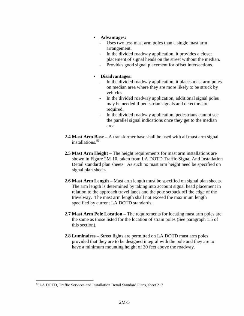
• Advantages:
- Uses two less mast arm poles than a single mast arm arrangement.
- In the divided roadway application, it provides a closer placement of signal heads on the street without the median.
- Provides good signal placement for offset intersections.
• Disadvantages: - In the divided roadway application, it places mast arm poles
on median area where they are more likely to be struck by vehicles.
- In the divided roadway application, additional signal poles may be needed if pedestrian signals and detectors are required.
- In the divided roadway application, pedestrians cannot see the parallel signal indications once they get to the median area.
2.4 Mast Arm Base – A transformer base shall be used with all mast arm signal
installations.83 2.5 Mast Arm Height – The height requirements for mast arm installations are
shown in Figure 2M-10, taken from LA DOTD Traffic Signal And Installation Detail standard plan sheets. As such no mast arm height need be specified on signal plan sheets.
2.6 Mast Arm Length – Mast arm length must be specified on signal plan sheets.
The arm length is determined by taking into account signal head placement in relation to the approach travel lanes and the pole setback off the edge of the travelway. The mast arm length shall not exceed the maximum length specified by current LA DOTD standards.
2.7 Mast Arm Pole Location – The requirements for locating mast arm poles are
the same as those listed for the location of strain poles (See paragraph 1.5 of this section).
2.8 Luminaires – Street lights are permitted on LA DOTD mast arm poles
provided that they are to be designed integral with the pole and they are to have a minimum mounting height of 30 feet above the roadway.
83 LA DOTD, Traffic Services and Installation Detail Standard Plans, sheet 217
2M-5
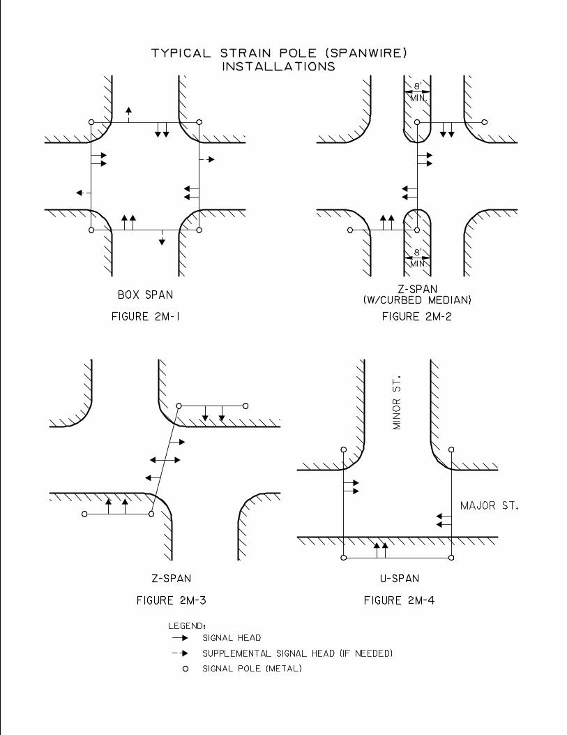
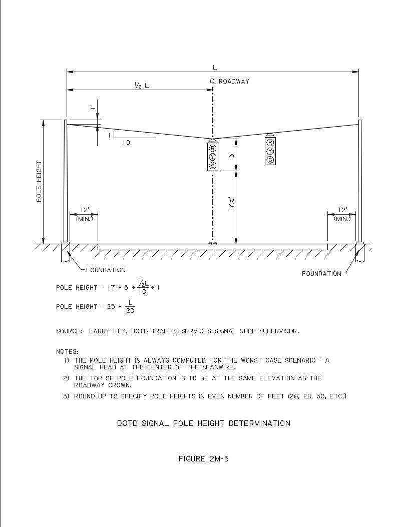
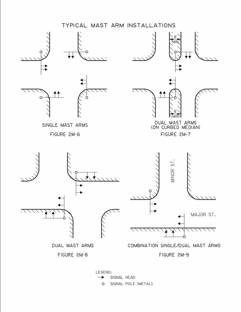
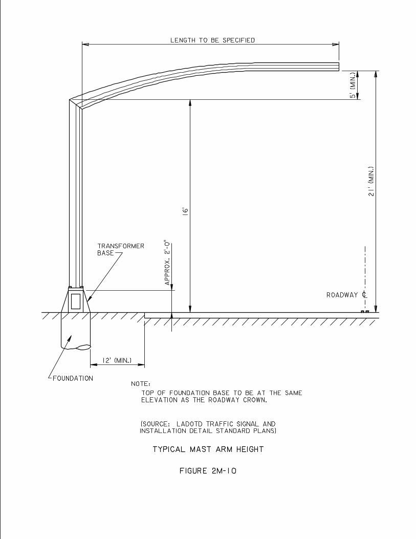
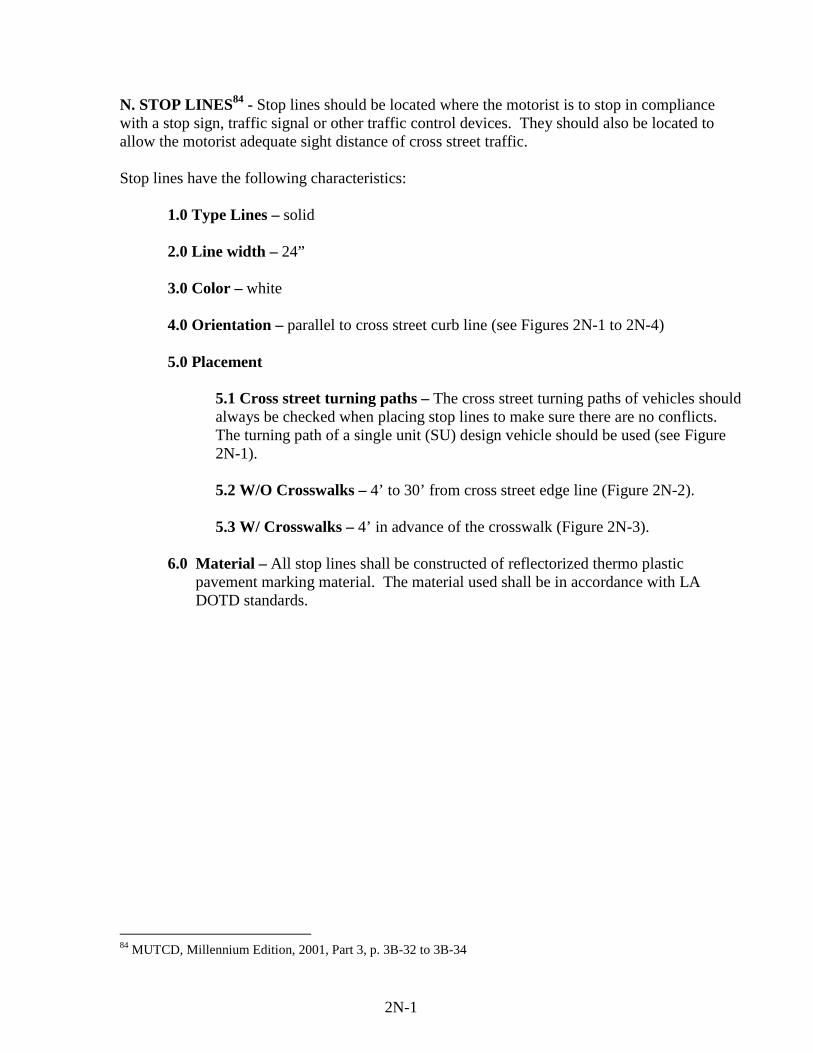
N. STOP LINES84 - Stop lines should be located where the motorist is to stop in compliance with a stop sign, traffic signal or other traffic control devices. They should also be located to allow the motorist adequate sight distance of cross street traffic. Stop lines have the following characteristics:
1.0 Type Lines – solid 2.0 Line width – 24”
3.0 Color – white
4.0 Orientation – parallel to cross street curb line (see Figures 2N-1 to 2N-4)
5.0 Placement
5.1 Cross street turning paths – The cross street turning paths of vehicles should always be checked when placing stop lines to make sure there are no conflicts. The turning path of a single unit (SU) design vehicle should be used (see Figure 2N-1). 5.2 W/O Crosswalks – 4’ to 30’ from cross street edge line (Figure 2N-2). 5.3 W/ Crosswalks – 4’ in advance of the crosswalk (Figure 2N-3).
6.0 Material – All stop lines shall be constructed of reflectorized thermo plastic
pavement marking material. The material used shall be in accordance with LA DOTD standards.
84 MUTCD, Millennium Edition, 2001, Part 3, p. 3B-32 to 3B-34
2N-1
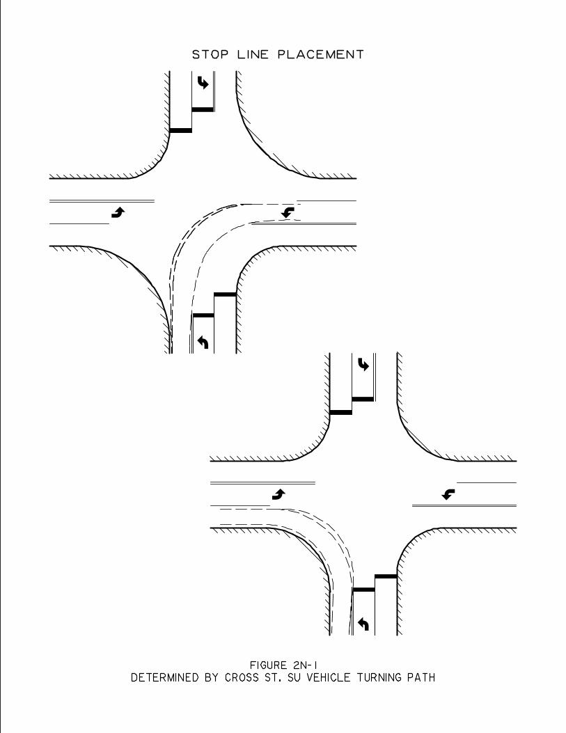
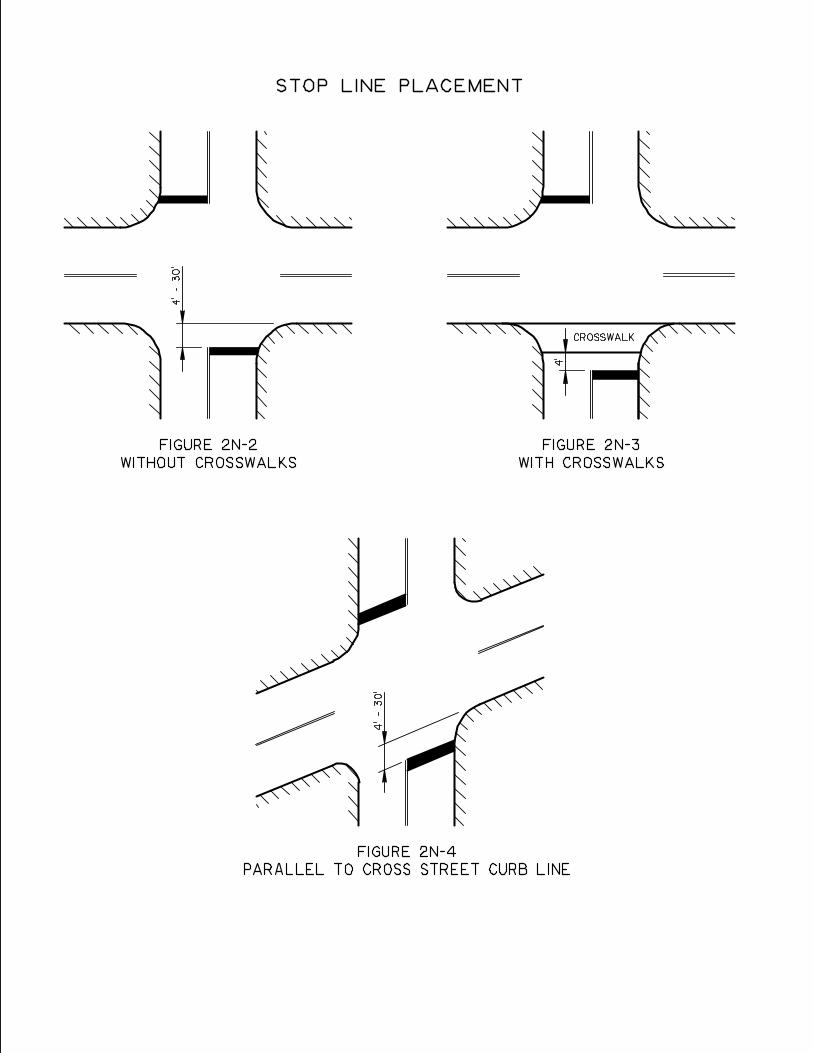
O. CROSS WALKS85
Crosswalks are used to define a location where pedestrians are to cross a roadway and to alert motorists as to the crossing location. They should be used only where there are significant conflicts between pedestrians and motorists. Crosswalks have the following characteristics: 1.0 Type lines – solid 2.0 Line width – 12”
3.0 Color – white
4.0 Crosswalk Width – 6 ft. (min.)
5.0 Location – Generally on line with sidewalk approaches. Engineering judgment must be
used.
6.0 Orientation – Normally, transverse lines are used. However, where additional crosswalk visibility is needed diagonal or longitudinal lines are used (see Figure 2O-1). In any case the crosswalk shall be oriented parallel to the cross street.
7.0 Materials – All crosswalks shall be constructed of reflectorized thermo plastic pavement
marking material. The material used shall be in accordance with LA DOTD Standards.
85 MUTCD, Millennium Edition, 2001, Part 3, p. 3B-34 to 3B- 36
2O-1
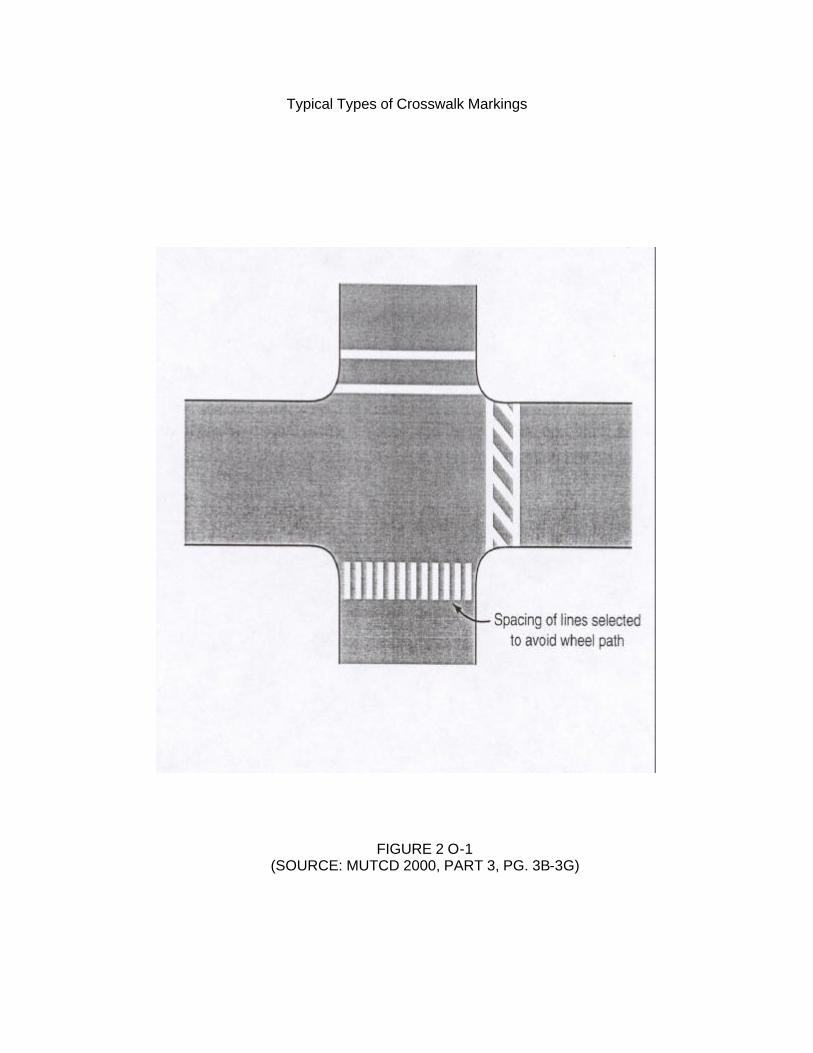
Typical Types of Crosswalk Markings
FIGURE 2 O-1 (SOURCE: MUTCD 2000, PART 3, PG. 3B-3G)
P. SIGNAL WIRING – After the signal head and signal detector arrangements/placements have been determined, the signal wiring required involves the following steps:
1.0 Signal Device Requirement - Determine the wiring requirement of each individual signal device by using Table 2P-1.
2.0 Mast Arm/Spanwire Runs - Determine the wiring required for the signal heads
depending on whether spanwire or mast arms are used. Figures 2P-1 and 2P-2 show typical wiring requirements for a wide variety of signal head arrangements on spanwires and mast arms respectively.
3.0 Detectors/Power/Interconnect Cable - Determine the wiring required for
detectors, power, and interconnect cables where applicable using Table 2P-1.
4.0 Sizing Conduit - Combine the wiring requirements in 2.0 and 3.0 above and size the conduit needed for each wiring run using Table 2P-2.
5.0 Example Problem - Figure 2P-3 is an example signal wiring problem
illustrating all of the above steps and showing a complete wiring diagram and accompanying wiring table.
2P-1

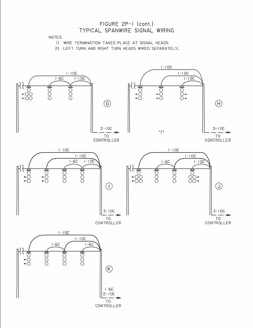
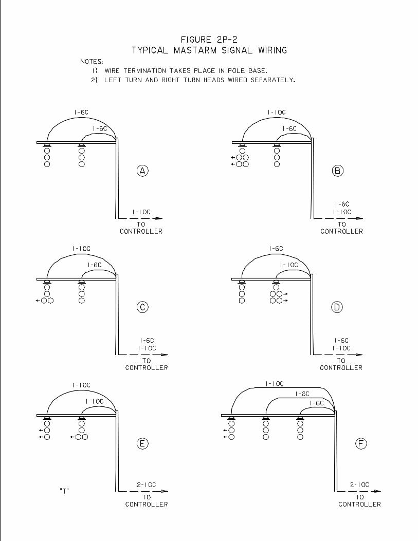
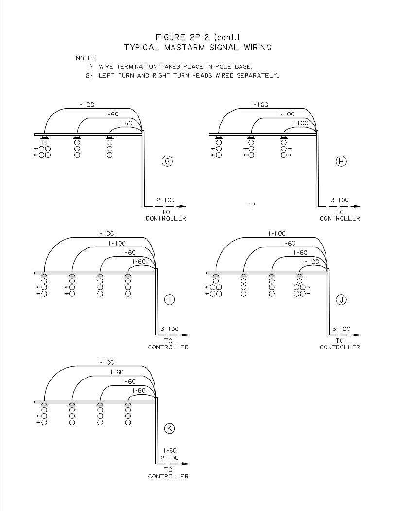
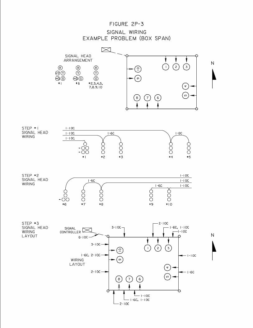
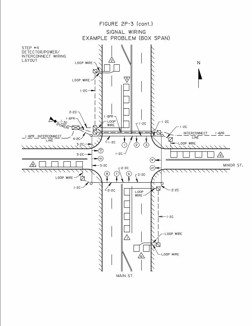
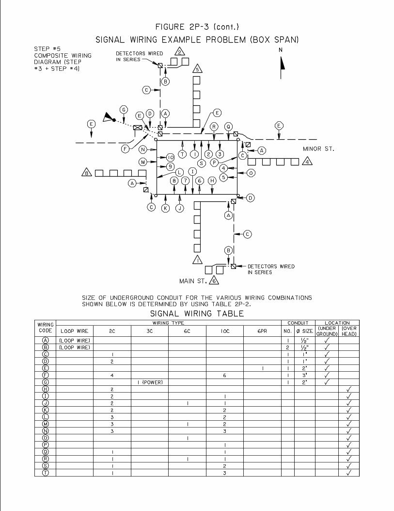
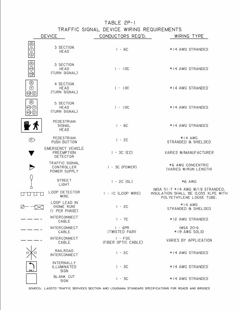
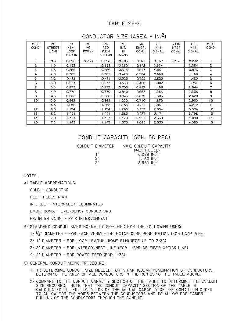
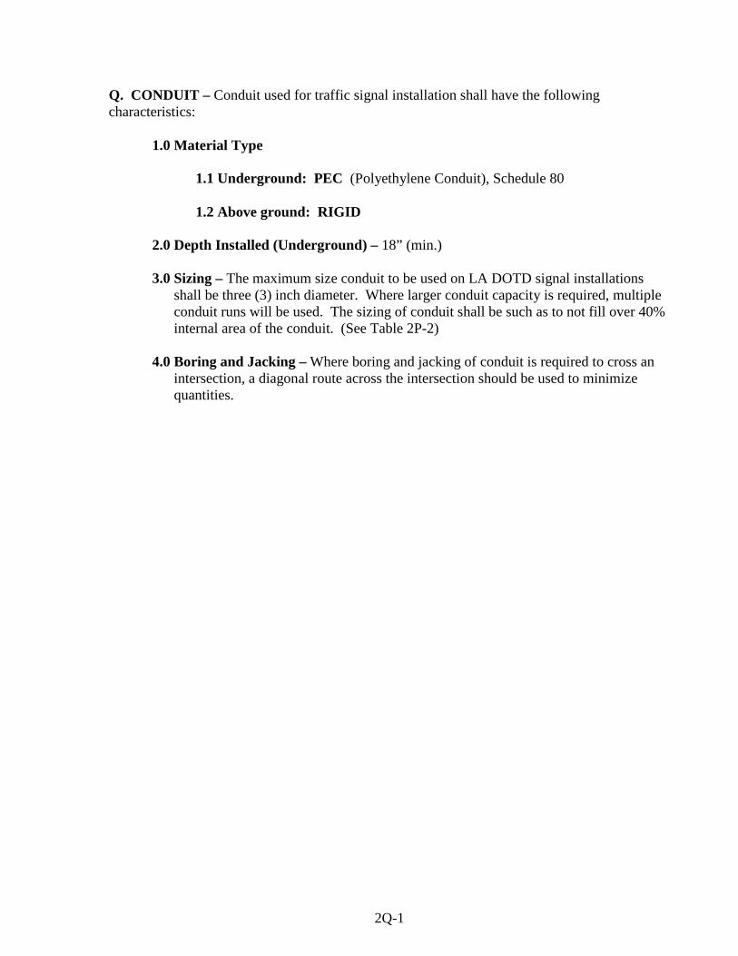
Q. CONDUIT – Conduit used for traffic signal installation shall have the following characteristics:
1.0 Material Type
1.1 Underground: PEC (Polyethylene Conduit), Schedule 80 1.2 Above ground: RIGID
2.0 Depth Installed (Underground) – 18” (min.) 3.0 Sizing – The maximum size conduit to be used on LA DOTD signal installations
shall be three (3) inch diameter. Where larger conduit capacity is required, multiple conduit runs will be used. The sizing of conduit shall be such as to not fill over 40% internal area of the conduit. (See Table 2P-2)
4.0 Boring and Jacking – Where boring and jacking of conduit is required to cross an
intersection, a diagonal route across the intersection should be used to minimize quantities.
2Q-1
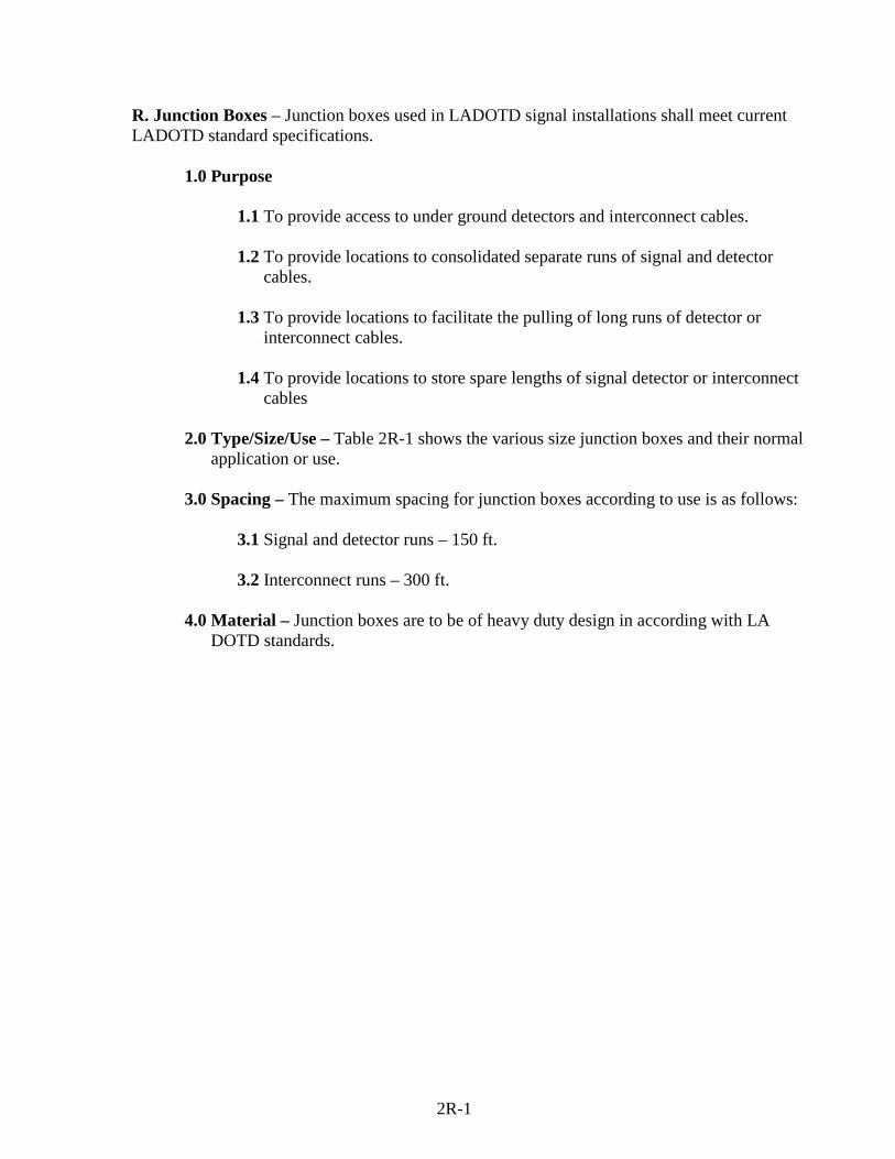
R. Junction Boxes – Junction boxes used in LADOTD signal installations shall meet current LADOTD standard specifications.
1.0 Purpose
1.1 To provide access to under ground detectors and interconnect cables. 1.2 To provide locations to consolidated separate runs of signal and detector
cables.
1.3 To provide locations to facilitate the pulling of long runs of detector or interconnect cables.
1.4 To provide locations to store spare lengths of signal detector or interconnect
cables
2.0 Type/Size/Use – Table 2R-1 shows the various size junction boxes and their normal application or use.
3.0 Spacing – The maximum spacing for junction boxes according to use is as follows:
3.1 Signal and detector runs – 150 ft. 3.2 Interconnect runs – 300 ft.
4.0 Material – Junction boxes are to be of heavy duty design in according with LA
DOTD standards.
2R-1
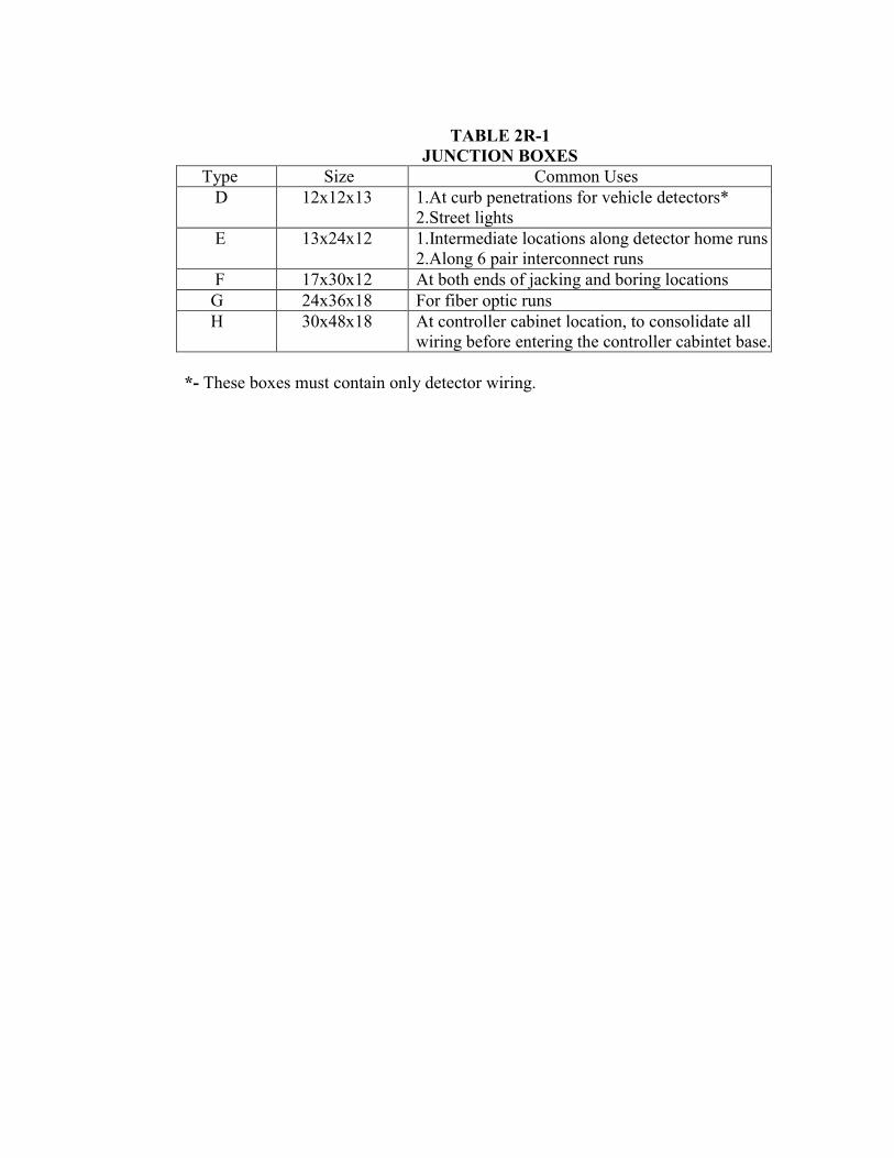
TABLE 2R-1
JUNCTION BOXES Type Size Common Uses D 12x12x13 1.At curb penetrations for vehicle detectors*
2.Street lights E 13x24x12 1.Intermediate locations along detector home runs
2.Along 6 pair interconnect runs F 17x30x12 At both ends of jacking and boring locations G 24x36x18 For fiber optic runs H 30x48x18 At controller cabinet location, to consolidate all
wiring before entering the controller cabintet base.
*- These boxes must contain only detector wiring.
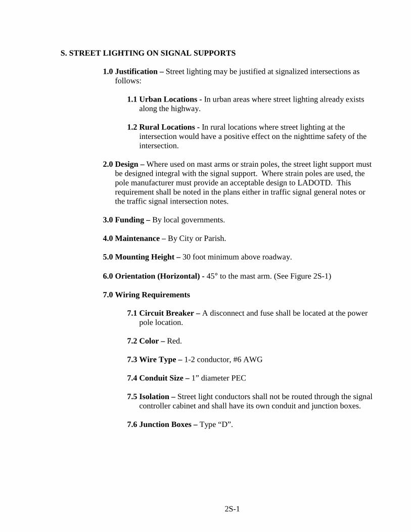
S. STREET LIGHTING ON SIGNAL SUPPORTS
1.0 Justification – Street lighting may be justified at signalized intersections as follows:
1.1 Urban Locations - In urban areas where street lighting already exists
along the highway. 1.2 Rural Locations - In rural locations where street lighting at the
intersection would have a positive effect on the nighttime safety of the intersection.
2.0 Design – Where used on mast arms or strain poles, the street light support must
be designed integral with the signal support. Where strain poles are used, the pole manufacturer must provide an acceptable design to LADOTD. This requirement shall be noted in the plans either in traffic signal general notes or the traffic signal intersection notes.
3.0 Funding – By local governments.
4.0 Maintenance – By City or Parish.
5.0 Mounting Height – 30 foot minimum above roadway.
6.0 Orientation (Horizontal) - 45° to the mast arm. (See Figure 2S-1)
7.0 Wiring Requirements
7.1 Circuit Breaker – A disconnect and fuse shall be located at the power
pole location. 7.2 Color – Red.
7.3 Wire Type – 1-2 conductor, #6 AWG
7.4 Conduit Size – 1” diameter PEC
7.5 Isolation – Street light conductors shall not be routed through the signal
controller cabinet and shall have its own conduit and junction boxes.
7.6 Junction Boxes – Type “D”.
2S-1
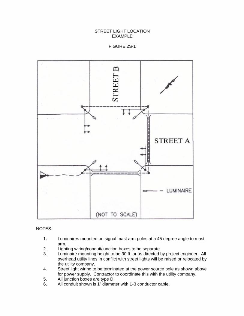
STREET LIGHT LOCATION EXAMPLE
FIGURE 2S-1
NOTES:
1. Luminaires mounted on signal mast arm poles at a 45 degree angle to mast arm.
2. Lighting wiring/conduit/junction boxes to be separate. 3. Luminaire mounting height to be 30 ft. or as directed by project engineer. All
overhead utility lines in conflict with street lights will be raised or relocated by the utility company.
4. Street light wiring to be terminated at the power source pole as shown above for power supply. Contractor to coordinate this with the utility company.
5. All junction boxes are type D. 6. All conduit shown is 1” diameter with 1-3 conductor cable.
T. FLASHING OPERATIONS – Flashing operations of a traffic signal shall comply with the MUTCD.
1.0 Justification – Flashing operations are normally justified at pretimed locations during these periods of the day when traffic volumes are too light to justify normal signal operations.
2.0 Methods of Initiation
2.1 Emergency – This type of flashing operation is usually initiated by
either a conflict monitor (malfunction management unit) or a manual switch.
2.2 Programmed – This type of flashing operation is programmed in the
controller to turn on and off at a particular time of day, usually when intersection traffic volumes are too light to justify normal signal operations. Isolated actuated traffic signals do not normally have a programmed flash mode operation.
3.0 Signal Display
3.1 All Red Flash – This type of flashing operation flashes red to all intersection approaches. It may be used under the following conditions:
3.1.1 Traffic Volumes – Traffic volumes on the two intersecting
streets are approximately equal. 3.1.2 Minor Street Delay – Minor street traffic would
experience excessive delays and/or hazard in trying to cross the major street with yellow flashing signal indications. Engineering judgment must be used to balance this benefit against the delay that will be experienced by the major street traffic.
3.1.3 Minor Street Sight Distance – Minor street traffic has
insufficient sight distance to safely cross the major street with yellow flashing signal indications.
3.2 Yellow-Red Flash – This type flashing operation is the most common
and flashes yellow to the major street and red to the minor street. Minor street sight distance as well as the difficulty the minor street traffic will have crossing the major street on flashing yellow must be considered.
2T-1
3.2.1 Protected Only Left Turn Signals (3 Section Heads) – These signal heads shall be flashed red regardless of what color indication the adjacent signal heads are flashing.
3.2.2 Protected/Permitted Left Turn Signals (5 Section
Heads) – These signals shall flash a circular indication of the same color as indications flashed in the adjacent signal head(s).
2T-2
U. ESTIMATED QUANTITIES
1.0 LA DOTD PAY ITEMS86 – Table 2U-1 is a listing of the item numbers for the frequently used pay items in preparing a set of signal plans. The table also shows the pay unit and decimal required for each item quantity.
2.0 SPECIAL MEASUREMENT METHODS
2.1 OVERHEAD WIRING AND SPANWIRE87 - The quantity of signal
and detector wiring when run in signal supports or overhead is not measured but is included either in the cost of the signal support or signal heads. Likewise signal spanwire is not measured but is included in the cost of the signal support.
2.2 SIGNAL SERVICE88 – Each signal service assembly includes the pole,
disconnect, ground rod and the wire and conduit on the service pole. These items are not measured separately.
2.3 LOOP DETECTORS89 – The measurement of loop detectors includes
the sawing of the roadway surface, the installed detector wire and the sealing of the saw cut.
3.0 PLANS WITH MULTIPLE SIGNAL LOCATIONS – Signal quantities
for plans with multiple signal locations shall be shown in one composite table with a separate column for the quantities of each location.
86 LA DOTD, Schedule of Pay Items (English version), April, 2001. 87 Louisiana Standard Specifications for Roads and Bridges, 2000 Edition, p. 502. 88 Louisiana Standard Specifications for Roads and Bridges, 2000 Edition, p. 502. 89 Louisiana Standard Specifications for Roads and Bridges, 2000 Edition, p. 503.
2U-1
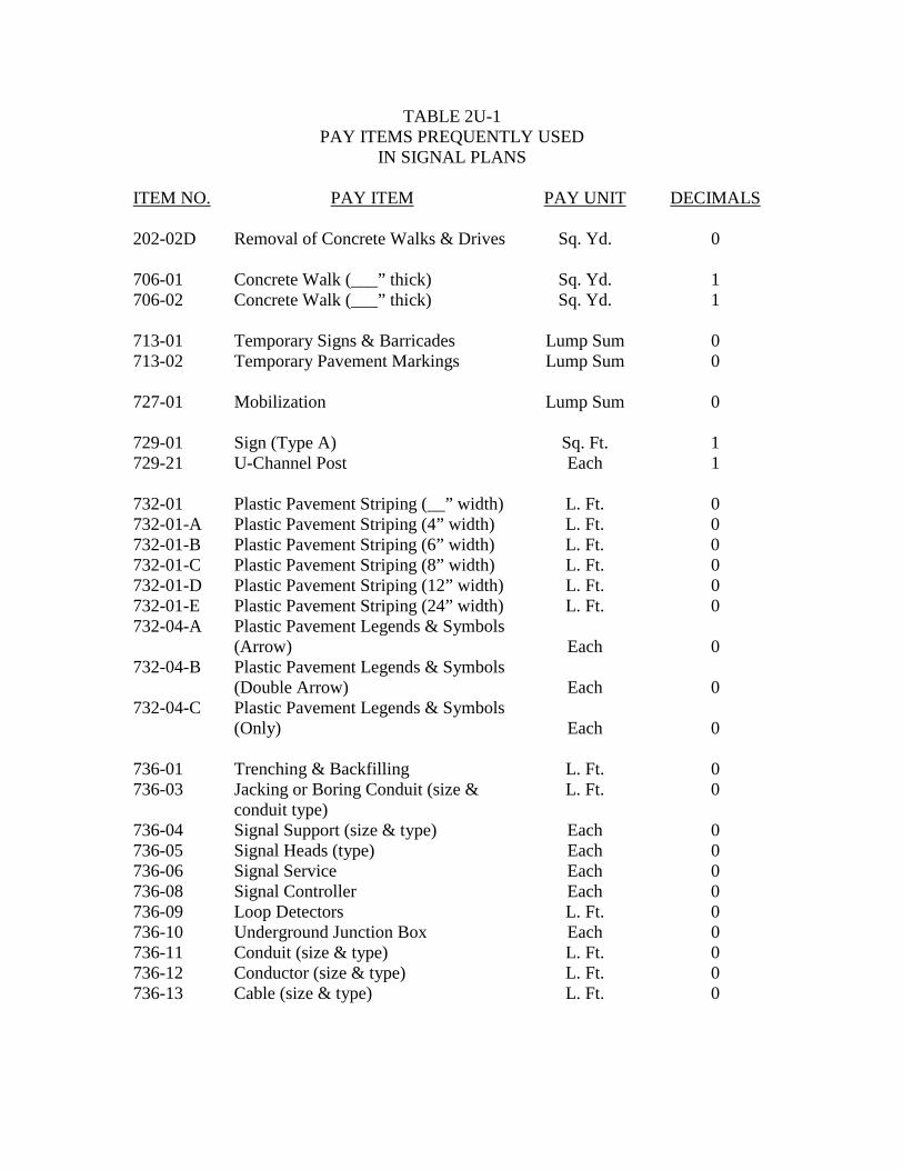
TABLE 2U-1 PAY ITEMS PREQUENTLY USED
IN SIGNAL PLANS ITEM NO. PAY ITEM PAY UNIT DECIMALS 202-02D Removal of Concrete Walks & Drives Sq. Yd. 0 706-01 Concrete Walk (___” thick) Sq. Yd. 1 706-02 Concrete Walk (___” thick) Sq. Yd. 1 713-01 Temporary Signs & Barricades Lump Sum 0 713-02 Temporary Pavement Markings Lump Sum 0 727-01 Mobilization Lump Sum 0 729-01 Sign (Type A) Sq. Ft. 1 729-21 U-Channel Post Each 1 732-01 Plastic Pavement Striping (__” width) L. Ft. 0 732-01-A Plastic Pavement Striping (4” width) L. Ft. 0 732-01-B Plastic Pavement Striping (6” width) L. Ft. 0 732-01-C Plastic Pavement Striping (8” width) L. Ft. 0 732-01-D Plastic Pavement Striping (12” width) L. Ft. 0 732-01-E Plastic Pavement Striping (24” width) L. Ft. 0 732-04-A Plastic Pavement Legends & Symbols
(Arrow)
Each 0
732-04-B Plastic Pavement Legends & Symbols (Double Arrow)
Each
0
732-04-C Plastic Pavement Legends & Symbols (Only)
Each
0
736-01 Trenching & Backfilling L. Ft. 0 736-03 Jacking or Boring Conduit (size &
conduit type) L. Ft. 0
736-04 Signal Support (size & type) Each 0 736-05 Signal Heads (type) Each 0 736-06 Signal Service Each 0 736-08 Signal Controller Each 0 736-09 Loop Detectors L. Ft. 0 736-10 Underground Junction Box Each 0 736-11 Conduit (size & type) L. Ft. 0 736-12 Conductor (size & type) L. Ft. 0 736-13 Cable (size & type) L. Ft. 0
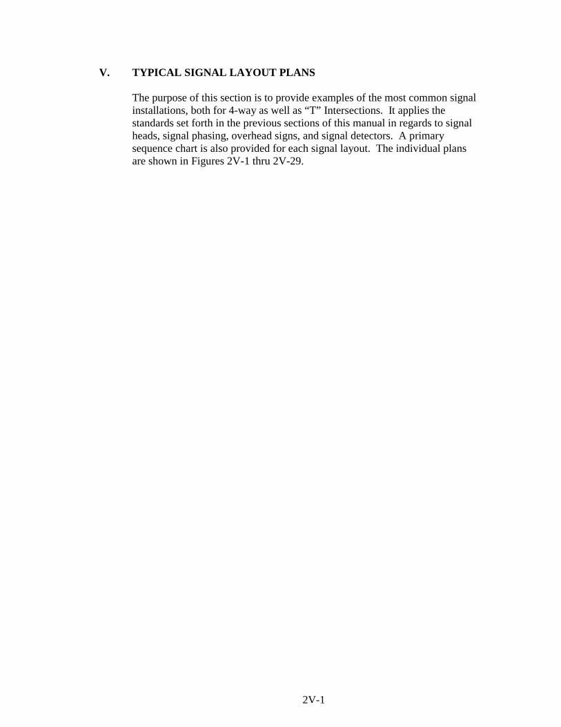
V. TYPICAL SIGNAL LAYOUT PLANS
The purpose of this section is to provide examples of the most common signal installations, both for 4-way as well as “T” Intersections. It applies the standards set forth in the previous sections of this manual in regards to signal heads, signal phasing, overhead signs, and signal detectors. A primary sequence chart is also provided for each signal layout. The individual plans are shown in Figures 2V-1 thru 2V-29.
2V-1
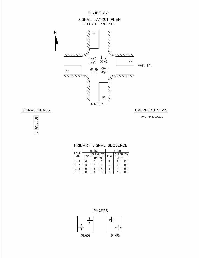
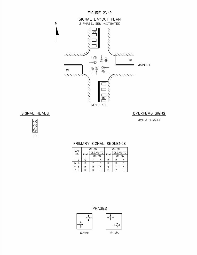

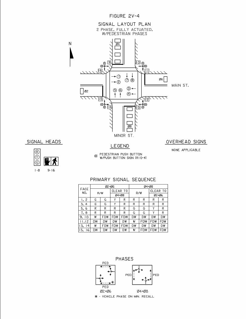
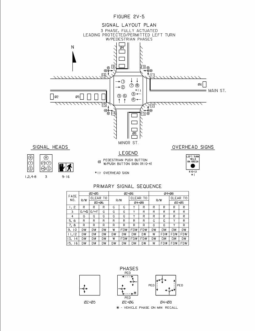
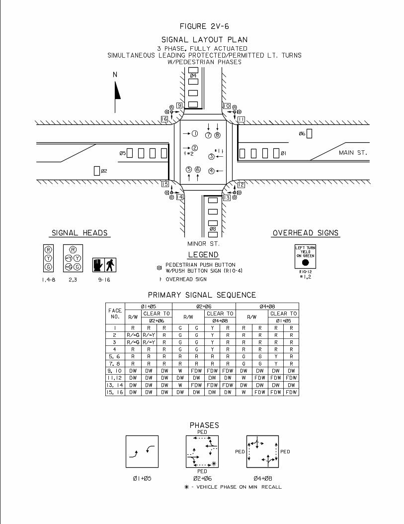
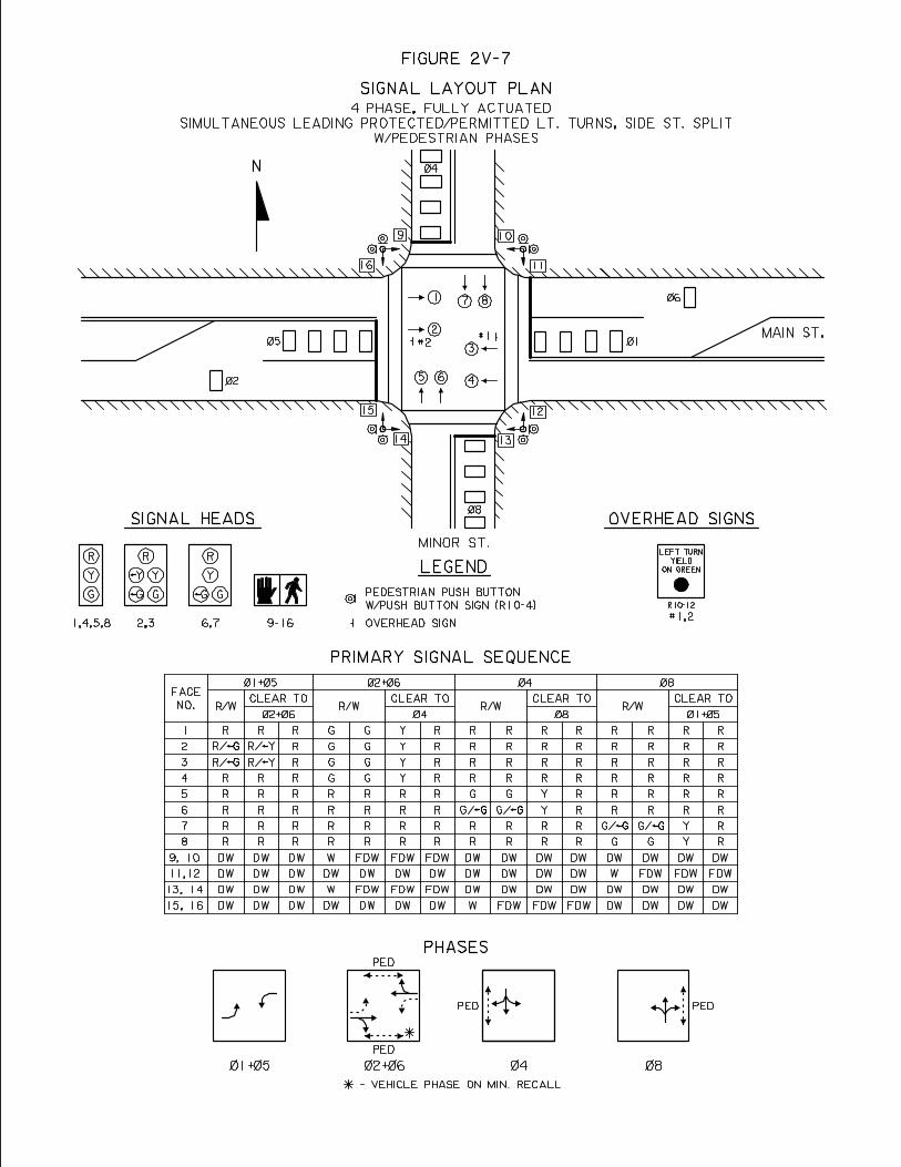
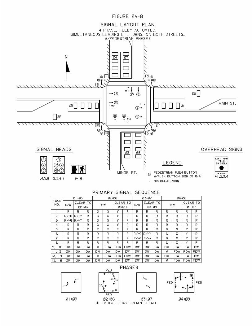
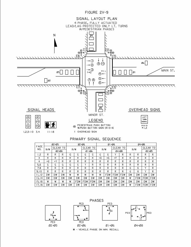
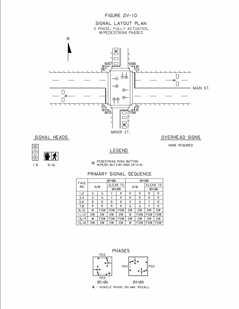
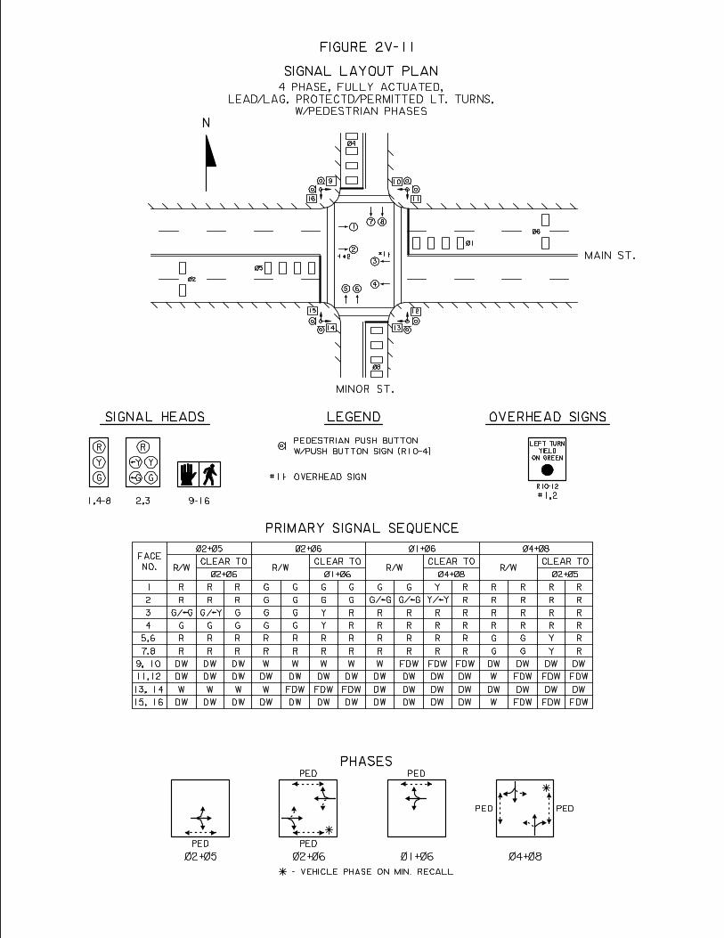

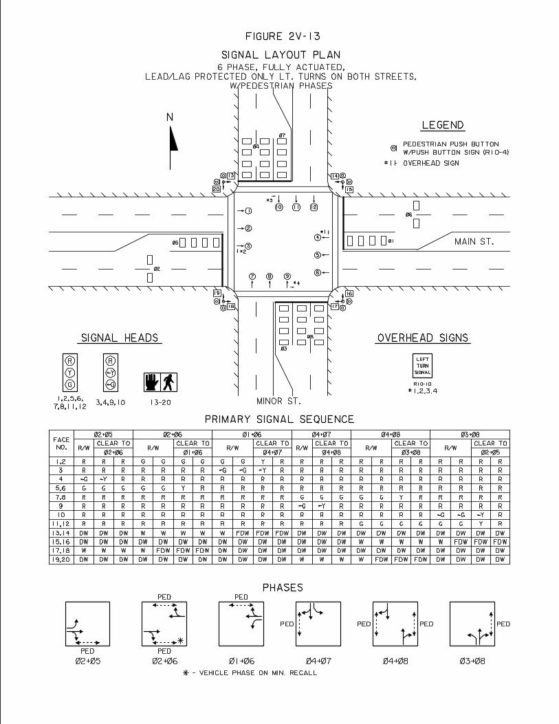
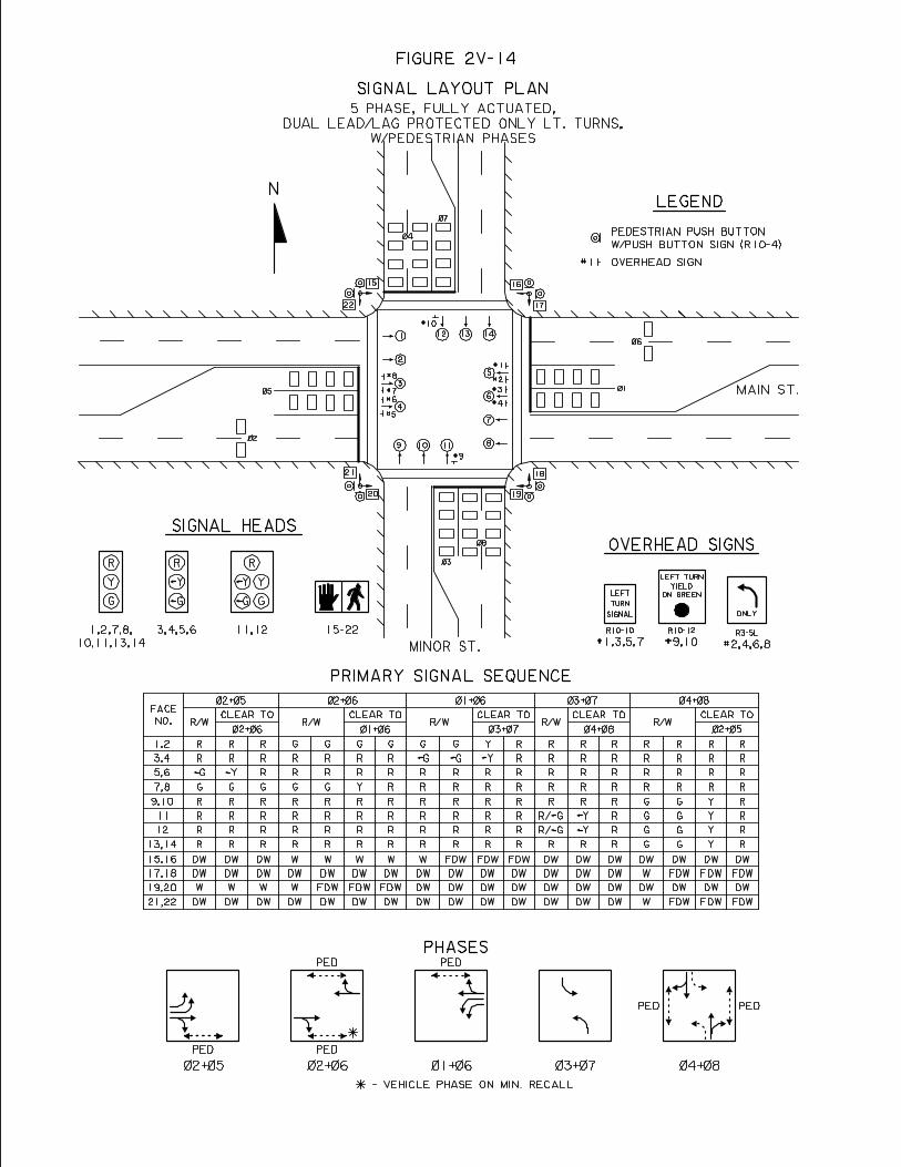
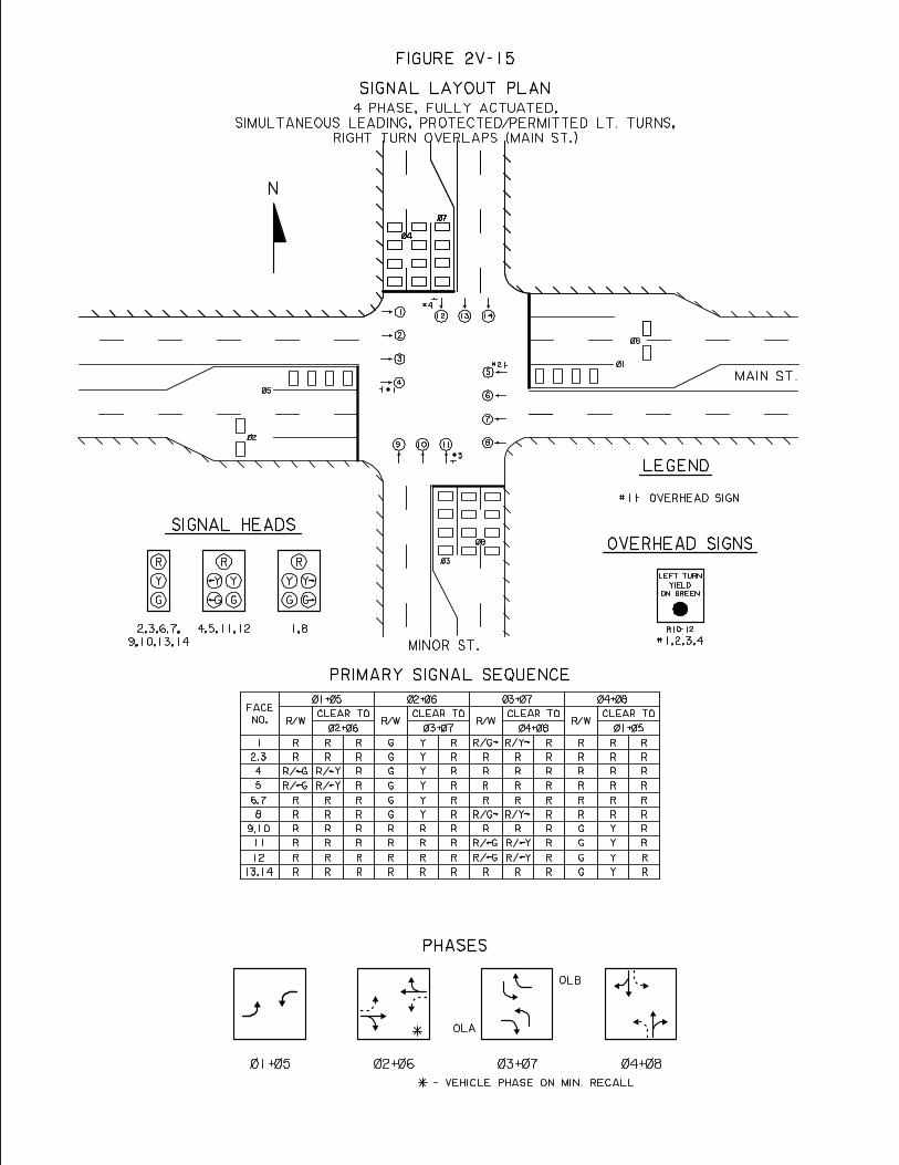
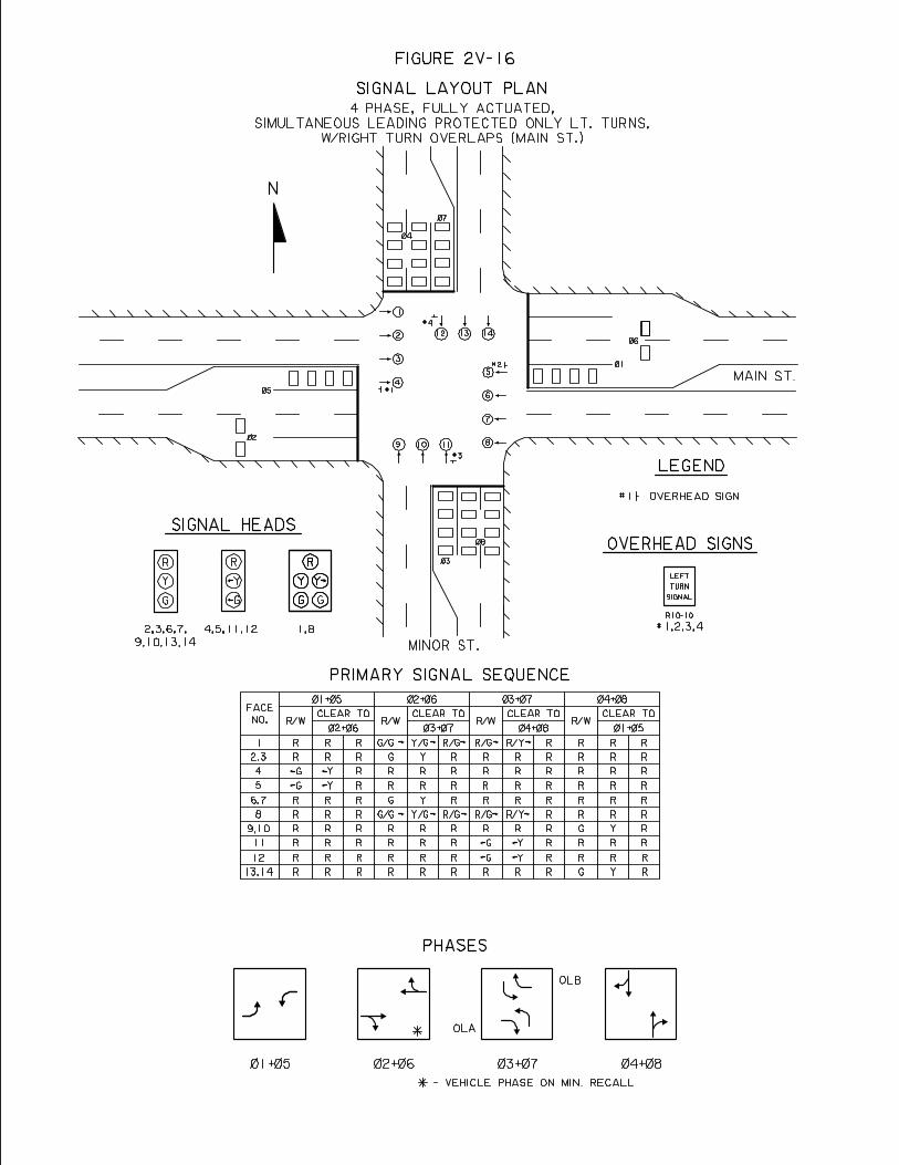
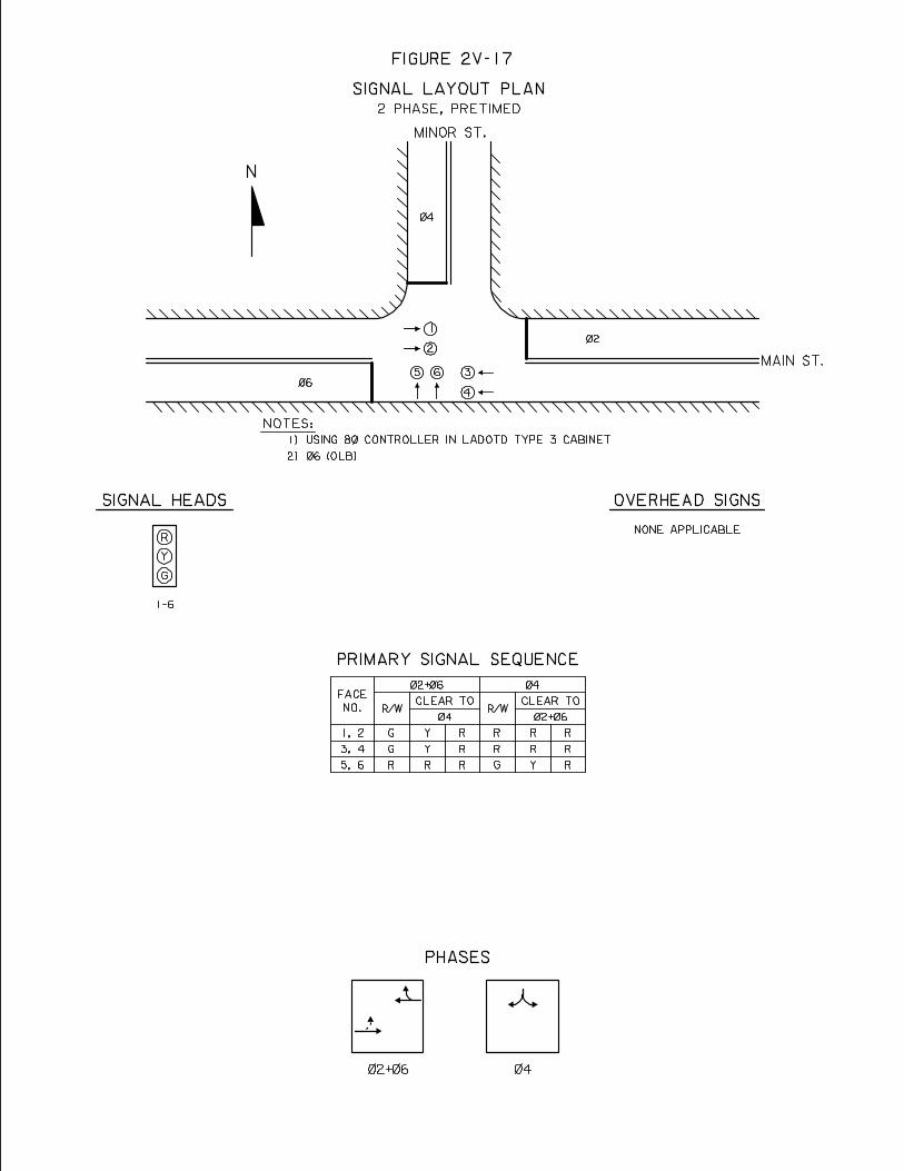
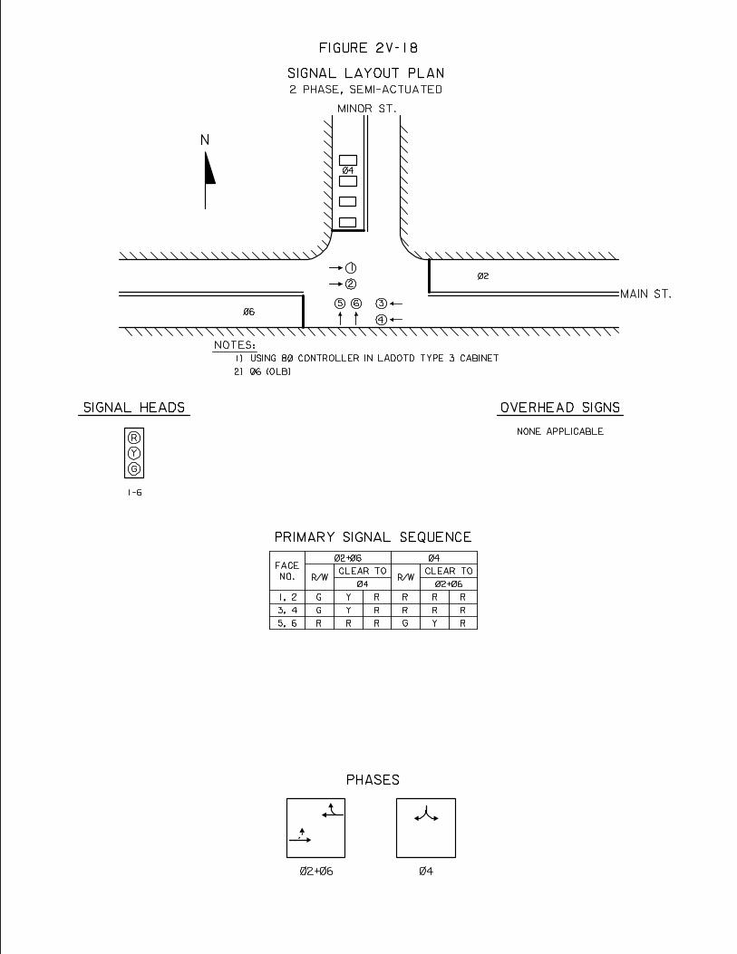
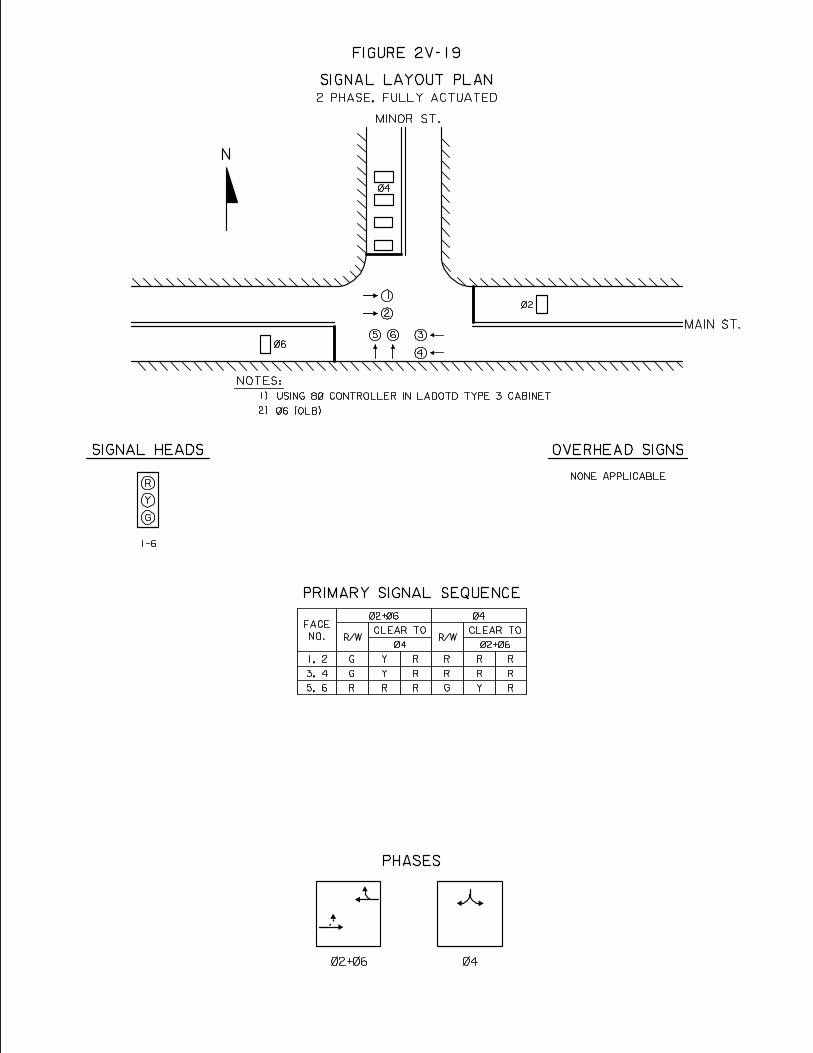
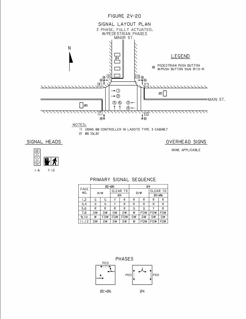
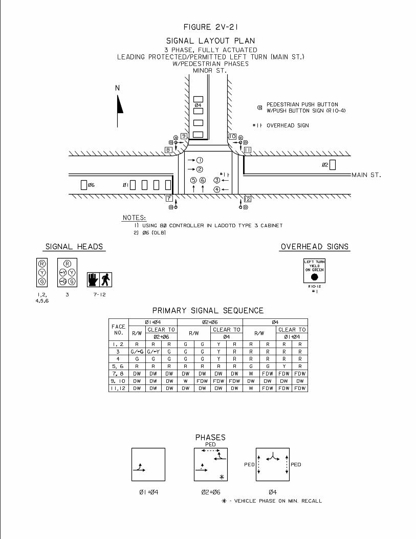
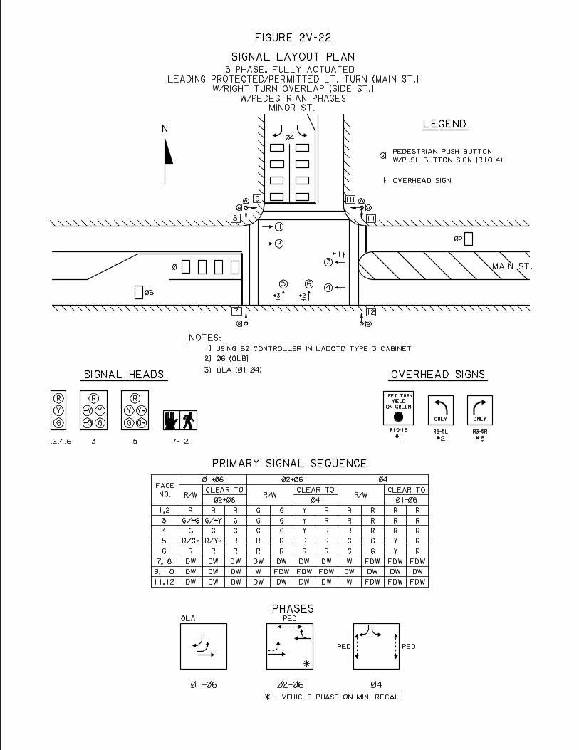

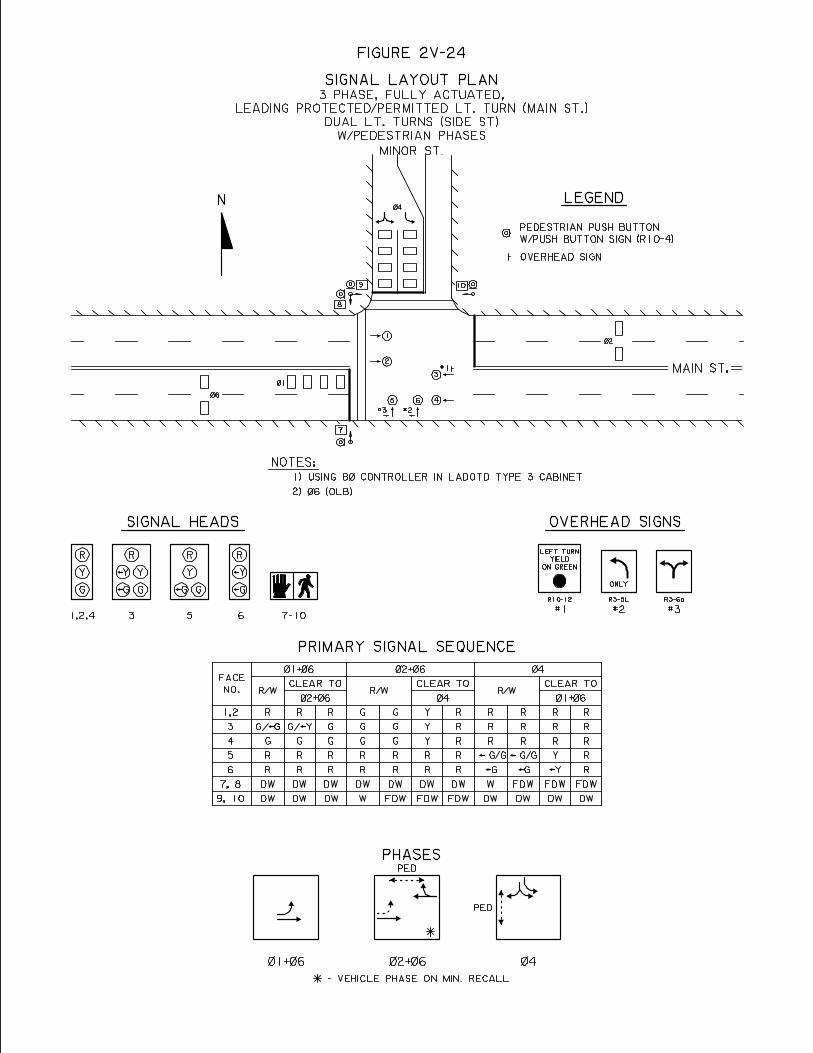
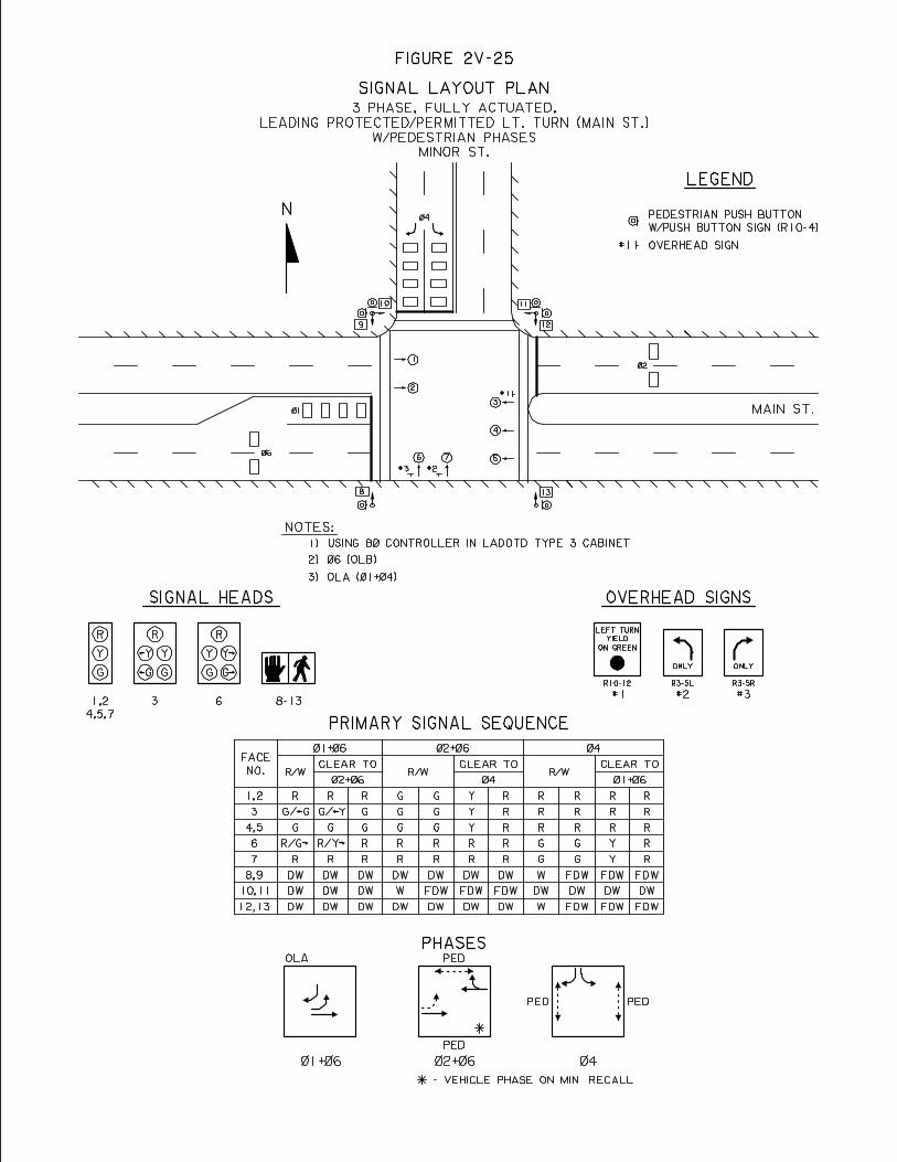
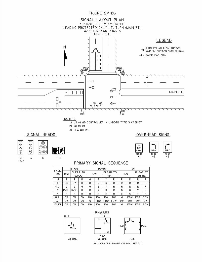
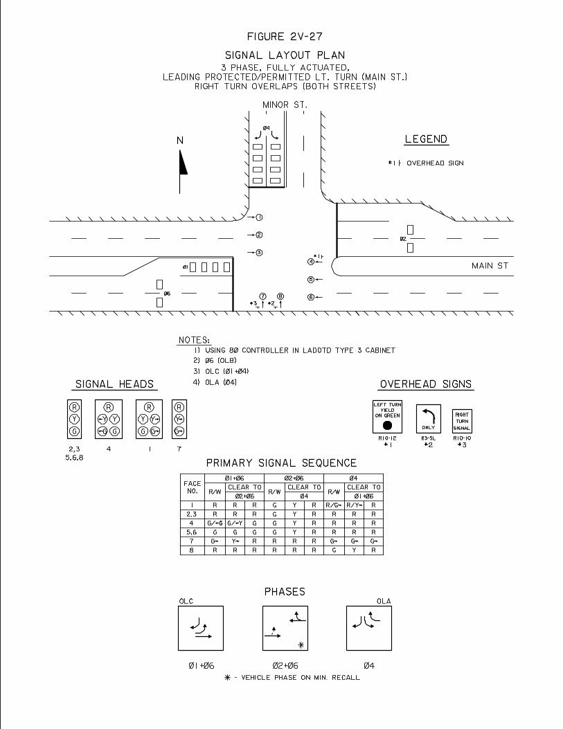
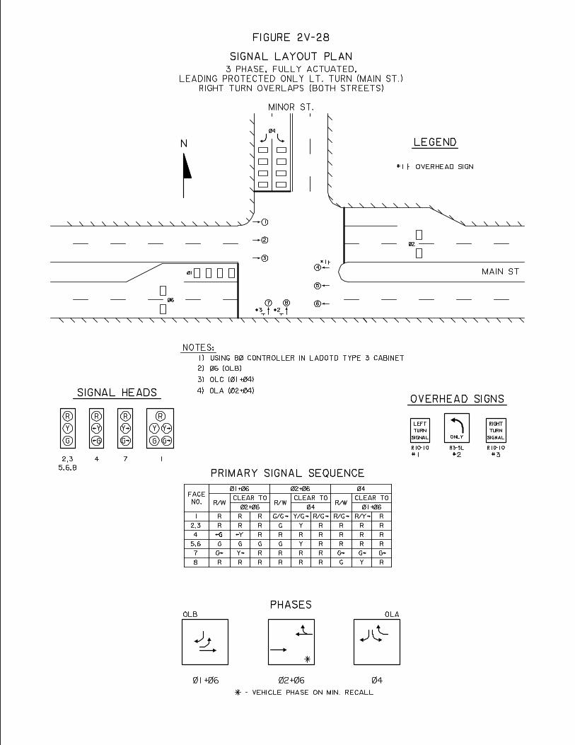
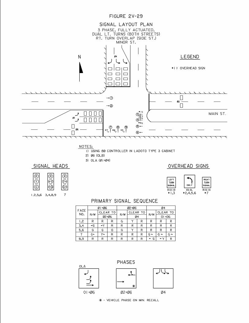
W. SIGNAL TURN ON PROCEDURES – The following steps are recommended for the activation of a new traffic signal.
1.0 Advance Flash Period – A new signal installation should be put on
flash operation for a period of two (2) weekdays prior to the activation of normal “stop and go” operation, so as to make motorists aware of its presence.
2.0 Publicity – The date and time of the activation of “stop and go”
operation should be advertised in both the local newspaper and on local radio stations both prior to and on the date of activation.
3.0 Activation – The actual activation of normal “stop and go” operation
should be made during an off peak traffic period.
4.0 Technical Help – Arrangements should be made to have a representative from the LA DOTD Traffic Services Section to be on site at the time that the signal is turned on normal “stop and go” operation. If a new brand of signal controller is being used, a manufacturer’s representative should also be present.
5.0 Signing Revisions – Once the signal is operational, any and all Stop
signs in conflict with the signal shall be removed. If necessary, Signal Ahead warning signs (W3-3) may be installed.
6.0 Police Assistance – Police assistance should be requested and be on
site at the time of signal activation to provide emergency traffic control in case of a malfunction and to help emphasis the new traffic control change to the motorists.
7.0 School Crossing – Should the intersection include a school crossing
with a crossing guard, the crossing guard should be familiarized with the new signal’s operation.
8.0 Fine Tuning – Shortly after the signal is turned on, the traffic
engineer should observe the signal’s operation during both peak and off peak periods to assure the adequacy of the signal’s timing parameters.
2W-1
CHAPTER 2 REFERENCES
Butzer, George L. and Pusey, Raymond S., Chapter 13, “Traffic Control Signals”, ITE, Traffic Engineering Handbook, 5th Edition, Washington, D.C.’ 1999. ITE, Traffic Detector Handbook, 2nd Edition, Institute of Transportation Engineers, Washington D.C.
Kell, James H., and Fullerton, Iris, ITE Manual of Traffic Signal Design, 2nd Edition, Prentice Hall, 1991.
Louisiana Department of Transportation and Development (LA DOTD), Louisiana Standard Specifications for Roads and Bridges, 2000 Edition.
Louisiana Department of Transportation and Development (LADOTD), Schedule Of Pay Items, 2000 Standard Specifications (English Version), April, 2001. Louisiana Department of Transportation and Development (LADOTD) Traffic Signal and Installation Detail Standard Plans. Northwestern University, Traffic Institute, Railroad Grade Crossing Workshop Notebook, Evanston, Illinois, January, 1999.
Northwestern University, Traffic Institute, Traffic Actuated Control Workshop Notebook, Evanston, Illinois, January, 1999.
Northwestern University, Traffic Institute, Traffic Signal Workshop Notebook, Evanston, Illinois, September, 1994.
Seyfried, Robert K., Northwestern University, Traffic Institute, “Timing of Traffic Signal Preemption at Intersections near Highway-Railroad Grade Crossings,” paper presented at Institute of Transportation, annual meeting, Chicago, Illinois, August 2001.
Transportation Research Board, National Research Council, Highway Capacity Manual, Washington, D.C., 2000 U.S. Department of Transportation, Federal Highway Administration (FHWA), Manual of Uniform Traffic Control Devices, (MUTCD), Millennium Edition, Washington D.C., 2001.
U.S. Department of Transportation Federal Highway Administration (FHWA), Traffic Control Devices Handbook, Washington D.C., U.S. Government Printing Office, 1983
2X-1
CHAPTER 3
SIGNAL PLANS A. GENERAL
The purpose of this chapter is to provide guidelines for the preparations of a set of signal design plans for LADOTD projects. Signal plans can be “stand alone” plans, that is plans containing only information on signal design and installation, or they can be a part of road construction plans. The plans sheet requirement for either case is as follows:
1.0 Part of Road Construction Plans – When signal plans are part of road plans and
cover only one signalized intersection, they shall include the following:
• General Notes Sheet • Summary of Quantities Sheet (If multiple signals are involved) • Signal Layout Sheet (For each signal) • Signal Timing/Operations Sheet (For each signal) • Railroad Preemption Sheet (If applicable, for each signal) • Signal Interconnect (If applicable)
2.0 “Stand Alone” Signal Plans – The signal plan sheet requirements for plans
containing only signal design and installation information is as follows:
• Title Sheet • General Notes Sheet • Summary of Quantities Sheet (If multiple signal are involved) • Signal Layout Sheet (For each signal) • Signal Timing/Operations Sheet (For each signal) • Railroad Preemption Sheet (If applicable, for each signal) • Signal Interconnect Sheet (If applicable)
3A-1
B. PLAN SHEETS REQUIRED The various signal plan sheets, their format and contents are described in this section. The basic format for all signal plan sheets contain the following information:
• Project Numbers – For the state, federal aid and city parish if applicable • Parish Name • Sheet Number • Schedule of Revisions • Professional Engineers Stamp
Additionally all plan signal sheets, with the exception of the Title Sheet, have a title block in their lower right hand corner containing the following information:
• “Traffic Signal Plans” notation • Project Title • Intersection or Corridor name (with Hwy. Route numbers) • Traffic Signal Inventory (TSI) number • Design Organization name • LA DOTD Title • Design Information (Initials of designer, detailer, checkers) • Scale • Date
Information specific to the various signal plan sheets is as listed below:
1.0 Title Sheet (Figure 3B-1) – As previously mentioned, a title sheet is required for “stand alone” signal plans. A typical example of a title sheet is seen in Figure 3B-1. It contains the following specific information:
• LADOTD Title • Type of Plans (Urban Systems Project, etc.)
• Project Title
• Location Map – w/project location and scale
• Index to sheets
• Survey information – if applicable.
• Edition of LA Standard Specifications applicable
3B-1
• Type of Construction
• Approval signatures
• Length of Project Table 2.0 Signal General Notes Sheet (Figure 3B-2) – This sheet contains, as the
name implies, notes of general nature that apply to all the signalized intersections in the plans. It generally includes items from the Louisiana Standard Specifications for Road and Bridges for which special emphasis is intended for the contractor. A typical signal general notes sheet containing the most frequently used notes is shown in Figure 3B-2.
3.0 Summary of Quantities Sheet (Figure 3B-3) – When a set of plans consists
of more than one signalized intersection design, a summary of quantities sheet is needed to summarize quantities both individually and for all the signalized intersections. Quantities are listed in LA DOTD item number order, with an item description, and in the units as specified by the LA DOTD Schedule of Pay Items. An example of such a sheet is seen in Figure 3B-3. If a set of plans has only one signalized intersection, its summary of quantities can be shown on the signal timing/operations plan sheet (See Figure 3B-5).
4.0 Signal Layout Sheet (Figure 3B-4) – A typical signal layout sheet is shown
in Figure 3B-4. This sheet shows the basic intersection geometry, the right-of-way, the location of underground utilities, channelization, pavement markings, driveways, ditches, utility poles and construction stationing (if available). The following information is also required on the sheet as shown in Figure 3B-4.
4.1 Signal Layout Diagram (on Figure 3B-4) – The signal layout
contains the following signal installation information.
• Signal controller cabinet – location • Electrical Service – location • Junction Boxes – number and location • Mast arm/Strain Poles – number, orientation, location • Signal heads – number, orientation, location • Spanwire signs – number, location, orientation • Signal detectors – number, pattern, phase assigned • Underground signal conduit – locations, type installation • Graphic Scale
4.2 Symbol Legend Chart (on Figure 3B-4) – This legend provides an
identification for each symbol shown on the diagram and is broken down into existing and proposed categories.
3B-2
4.3 Intersection Specific Notes (on Figure 3B-4) – This set of notes applies to the signal installation at this intersection only. It should not repeat notes covered in the signal General Notes Section. Items typically covered in these notes include but are not limited to:
• Signal Controller/Cabinet – Specifies installation and type • Electrical Service – Specifies installation • Junction Boxes – Specifies installation and type • Mast Arm/Strain Poles – Specifies type installation and size • Signal detectors – Specifies installation • References – Refers to the signal general notes and the signal
timing and operations sheets for additional information. • Speed Limits – Posted speed limits on all intersection
approaches
4.4 Signal Indications Diagram (on Figure 3B-4) – This diagram shows the signal indication arrangement for each head shown on the signal layout diagram. Typically it also specifies the signal indication lense size and signal head (housing) color.
4.5 Sign Layout Diagram (on Figure 3B-4) – This diagram shows the
sign type, MUTCD designation, legend, and size for each sign called for on the signal layout diagram. If a non-standard sign, such as a street name sign, is called for, its size, color and legend must be specified.
4.6 Free Operations Signal Phasing Diagram (on Figure 3B-4) – This
diagram shows all the variable sequences of which the signal is capable in its “free operations” mode. The diagram also shows the signal’s primary sequence (i.e., the sequence the signal would assume with maximum calls on all phases). Any signal phase placed on recall is also noted on this diagram.
4.7 Peak Hour Volumes Diagram (on Figure 3B-4) – This diagram
shows the peak hour traffic turning movement volumes at the intersection for the morning, noon, and afternoon peak hours on which the signal design was based. These volumes can reflect the current traffic using the intersection, or future traffic projections as in the case of new roadways, added intersection approaches, or new commercial developments. If projected volumes are shown it is to be noted as such on the diagram.
4.8 Information Sources (on Figure 3B-4) – The source of the survey,
base map, and traffic count information is to be listed on this sheet.
3B-3
5.0 Signal Timing/Operations Sheet (See Figure 3B-5) – A typical signal
timing/operations sheet contains specific information concerning the timing, phasing, and installation of the signal. The following information is required on this plan sheet.
5.1 Wiring Diagram (On Figure 3B-5) – This diagram shows the wiring
required to accommodate the signal heads, detectors, signal controllers and power source for the signal installation shown on the signal layout sheet. For clarity purposes, the combination of conductors required in each different section of the wiring diagram is designated with a letter code corresponding to a wiring combination shown in the signal wiring schedule.
5.2 Signal Wiring Schedule (On Figure 3B-5) – This chart describes the
various conductor combinations as designated by a letter code on the wiring diagram. It also specifies the conduit size needed for each particular combination of conductors run underground.
5.3 Legend (On Figure 3B-5) – This legend diagram identifies the
various symbols shown on the wiring diagram. It is an abbreviated version of the legend shown on the intersection layout plan sheet.
5.4 Signal Phasing Diagrams (On Figure 3B-5) –
• Free Operation Signal Phasing Diagram – This diagram
shows all the variable sequences of which a signal is capable in its “free operations” mode. The diagram also shows the signal’s primary sequence as well as any phases placed on recall. This diagram is repeated from the signal layout sheet to aid in reading the signal primary sequence chart.
• TOD Signal Phasing – A separate time of day (TOD) signal
phasing diagram is to be provided if timing plans are specified that use a phasing sequence different from that shown on the free operation phasing diagram.
5.5 Signal Indications Diagram (On Figure 3B-5) – This diagram
shows the signal indication arrangement for each head shown on the signal layout diagram. This diagram is repeated from the intersection layout sheet to aid in reading the signal primary sequence chart.
5.6 Signal Primary Sequence Chart (On Figure 3B-5) – This chart
shows the signal indication(s) displayed by each signal head for each separate interval during the signal’s primary sequence. This includes both right of way (R/W) and clearance intervals. Additionally, this
3B-4

chart shows the indication display for each head when the signal is put into its emergency flash mode.
5.7 Head Assignment Chart (On Figure 3B-5) – This chart shows the
phase assignment (including overlaps) for the signal indications on each signal head.
5.8 Signal Pole Table (On Figure 3B-5) – This table locates the signal
support as to intersection quadrant (also noted on the wiring diagram) and by stationing and offset (if available). It also specifies the signal pole height for strain pole installations and mast arm lengths for the single or double mast arm installations.
5.9 Phase Timing Parameters Table (On Figure 3B-5) – This table
contains all the timing parameters applicable for the type of signal specified in the plans. The timing is shown for each separate signal phase in addition to its recall status. The timing of these parameters is discussed in Chapter 2, Section D, Subsections 3.0 and 4.0 of this Manual. Typically there are notes under this table that specify when Max II timing is used, the “start up” phases when the signal is turned on, the “flash time” on the conflict monitor, and the “red revert” timing. The “flash time” on the conflict monitor is the length of time the signal will flash before going into “stop and go” operation when the controller is powered up (normally 7 seconds). When the signal rests in an all red mode and a phase is serviced, upon termination of the phase the “red revert” is the minimum amount of red time that must be displayed to that phase before it can be serviced again (normally 6 seconds).
5.10 Time of Day (TOD) Signal Phasing/Timing Plans (On Figure 3B-
5) – This diagram is provided if there is a need for timing plans beyond that which can be provided by the MAX I and MAX II timing functions of the signal controller, or the signal is coordinated with adjacent signals and must adhere to a prescribed cycle length. The time of operation, cycle length, offsets and force offs are shown for each plan. Additionally a TOD signal phasing diagram is provided for the timing plans if the phasing is different from that shown in the free operation signal phasing diagram. The timing for such plans is discussed in Chapter 2, Section D, Subsection 5.0 of this Manual. Notes at the bottom of this diagram indicate the use of MAX II for the timing plans, and the notations for clearance intervals and local time zero. Also, if the signal phasing changes in any of the timing plans it is so noted.
3B-5
5.11 Loop Installation Chart (On Figure 3B-5) – This chart provides
information concerning the number, size, location and pattern for the signal detectors for each signal phase. Also shown is the detector mode, its card and channel assignment and any special features such as programmed delay. Distances from the stop line are measured from the back of the stop line to the front of the detector pattern. Any detectors located in front of the stop line are shown with “negative” measurements.
5.12 Emergency Preemption Sequence Diagram (On Figure 3B-5) – If
emergency preemption is included in the signal design, an emergency preemption phasing diagram is needed to show all the phasing sequences possible when the signal is preempted. The phase in which normal signal operations is to resume after preemption is to be designated. Normally preemption is limited to state highways and not side streets. Exceptions to this would be if there were a fire or EMS station or hospital located on the side street.
5.13 Summary of Quantities Table (On Figure 3B-5) – As previously
mentioned, if a set of signal plans has only one signalized intersection, the summary of quantities table is included on the signal timing/operations sheet. If the plans contain multiple signalized intersections, a separate quantity sheet must be provided that shows the quantities for all intersections. Quantities are listed in LA DOTD item number order, with an item description and in the units as specified by the LA DOTD Schedule of Pay Items.
6.0 Railroad Preemption Sheet (Figure 3B-6) – If railroad preemption is
needed because of the nearness of the traffic signal to a railroad grade crossing, a railroad preemption plan sheet is required. The following information is required on this plan sheet.
6.1 Railroad Preemption Sequence Diagram (On Figure 3B-6) – This
diagram shows the preemption sequence that the signal would take to clear the track prior to the train’s arrival, regardless of the signal phase when the train is detected.
6.2 Railroad Preemption Signal Sequence Chart (On Figure 3B-6) –
This chart shows the signal indications displayed by each signal head for the “clear to railroad preemption” sequence, the “track clearance” sequence, the “preemption hold” sequence, and the “release to normal operations” sequence. This chart also shows the use of “blank out” signs, to prohibit turning movements across the track during the track clearance, and preemption hold sequences. The actual railroad
3B-6
preemption timing is discussed in Section F of Chapter 2 of this Manual and is usually provided by the Department.
7.0 Signal Interconnect Sheet (Figure 3B-7) – If multiple signal locations are
coordinated in their operation, a signal interconnect plan sheet is required. The following is required on this plan sheet:
7.1 Routing Diagram (On Figure 3B-7) – This diagram shows the
general interconnect line routing between all coordinated signal locations in the plans. This routing diagram also designates the size and the approximate locations of junction boxes to be used along this routing, and the location of the signal controller cabinets to be accessed.
7.2 Notes – The notes accompanying the routing diagram generally cover
the follwing
• Interconnect Line (Type) • Conduit (Size, Type, Min. Depth) • Junction Boxes (Type, Spacing) • Buried Cable Warning Sign (Size, Legend, Color, Location)
7.3 Legend – The legend defines the various symbols used on the routing
diagram.
3B-7
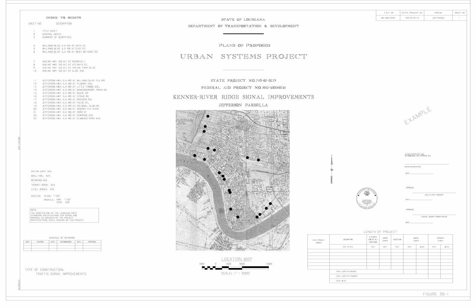
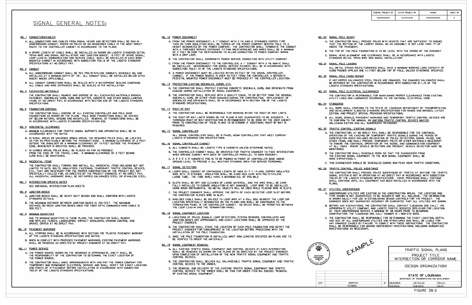
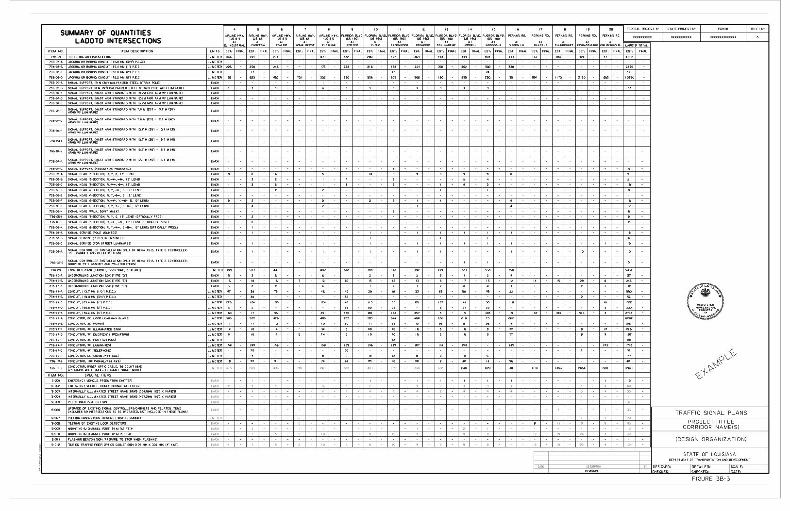
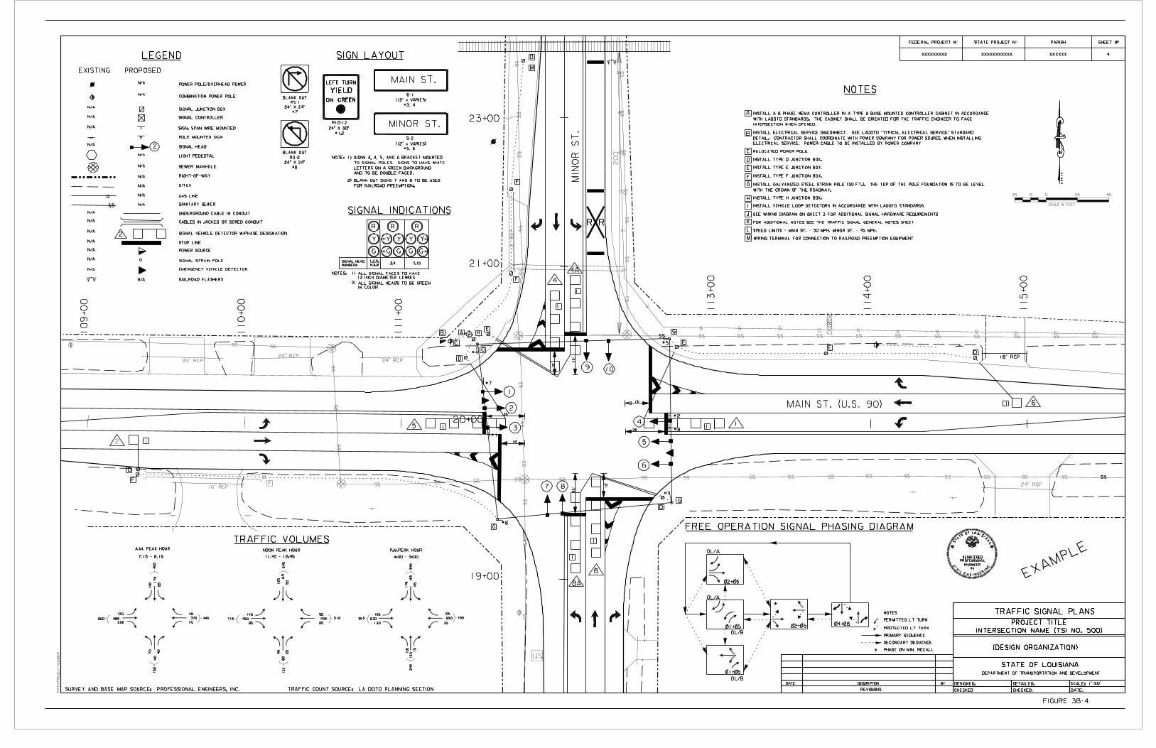
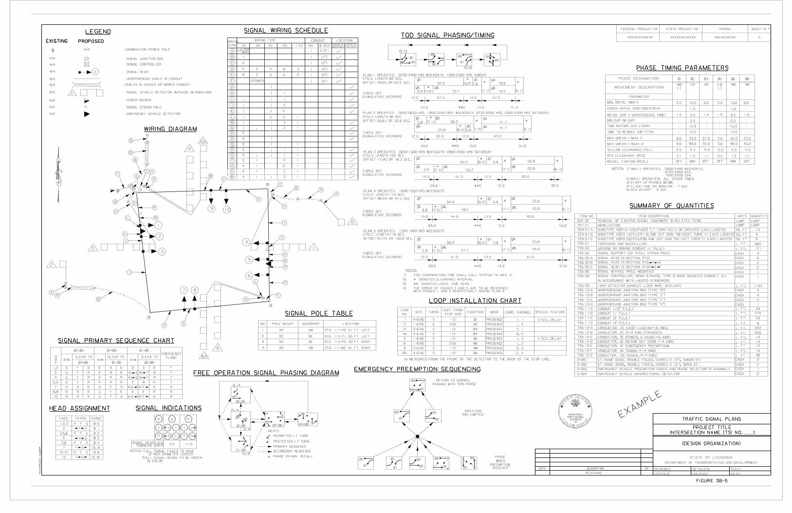

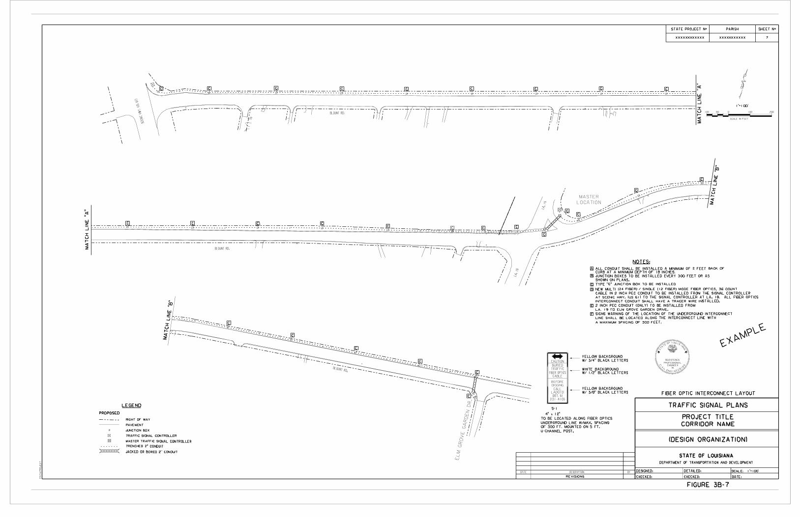
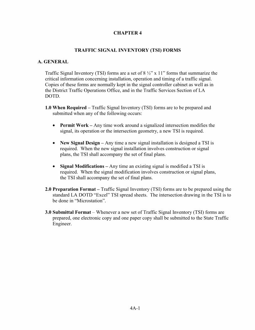
CHAPTER 4
TRAFFIC SIGNAL INVENTORY (TSI) FORMS A. GENERAL
Traffic Signal Inventory (TSI) forms are a set of 8 ½” x 11” forms that summarize the critical information concerning installation, operation and timing of a traffic signal. Copies of these forms are normally kept in the signal controller cabinet as well as in the District Traffic Operations Office, and in the Traffic Services Section of LA DOTD.
1.0 When Required – Traffic Signal Inventory (TSI) forms are to be prepared and
submitted when any of the following occurs:
• Permit Work – Any time work around a signalized intersection modifies the signal, its operation or the intersection geometry, a new TSI is required.
• New Signal Design – Any time a new signal installation is designed a TSI is
required. When the new signal installation involves construction or signal plans, the TSI shall accompany the set of final plans.
• Signal Modifications – Any time an existing signal is modified a TSI is
required. When the signal modification involves construction or signal plans, the TSI shall accompany the set of final plans.
2.0 Preparation Format – Traffic Signal Inventory (TSI) forms are to be prepared using the
standard LA DOTD “Excel” TSI spread sheets. The intersection drawing in the TSI is to be done in “Microstation”.
3.0 Submittal Format – Whenever a new set of Traffic Signal Inventory (TSI) forms are
prepared, one electronic copy and one paper copy shall be submitted to the State Traffic Engineer.
4A-1
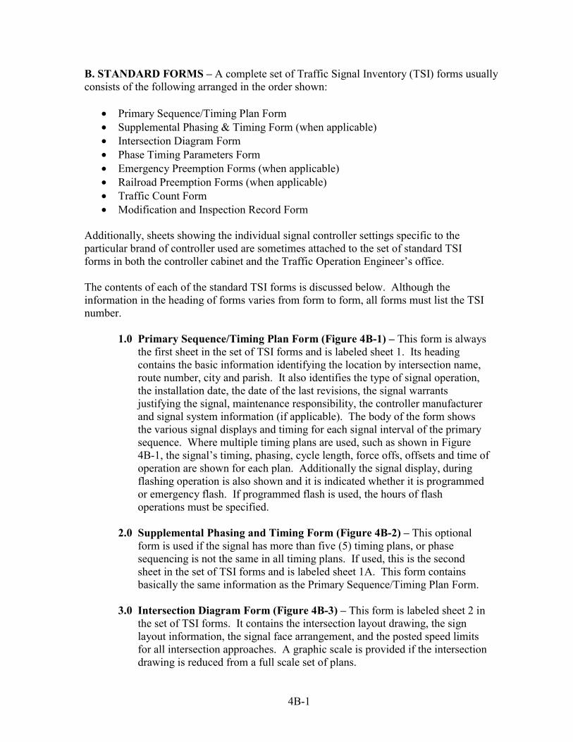
B. STANDARD FORMS – A complete set of Traffic Signal Inventory (TSI) forms usually consists of the following arranged in the order shown:
• Primary Sequence/Timing Plan Form • Supplemental Phasing & Timing Form (when applicable) • Intersection Diagram Form • Phase Timing Parameters Form • Emergency Preemption Forms (when applicable) • Railroad Preemption Forms (when applicable) • Traffic Count Form • Modification and Inspection Record Form
Additionally, sheets showing the individual signal controller settings specific to the particular brand of controller used are sometimes attached to the set of standard TSI forms in both the controller cabinet and the Traffic Operation Engineer’s office. The contents of each of the standard TSI forms is discussed below. Although the information in the heading of forms varies from form to form, all forms must list the TSI number.
1.0 Primary Sequence/Timing Plan Form (Figure 4B-1) – This form is always the first sheet in the set of TSI forms and is labeled sheet 1. Its heading contains the basic information identifying the location by intersection name, route number, city and parish. It also identifies the type of signal operation, the installation date, the date of the last revisions, the signal warrants justifying the signal, maintenance responsibility, the controller manufacturer and signal system information (if applicable). The body of the form shows the various signal displays and timing for each signal interval of the primary sequence. Where multiple timing plans are used, such as shown in Figure 4B-1, the signal’s timing, phasing, cycle length, force offs, offsets and time of operation are shown for each plan. Additionally the signal display, during flashing operation is also shown and it is indicated whether it is programmed or emergency flash. If programmed flash is used, the hours of flash operations must be specified.
2.0 Supplemental Phasing and Timing Form (Figure 4B-2) – This optional
form is used if the signal has more than five (5) timing plans, or phase sequencing is not the same in all timing plans. If used, this is the second sheet in the set of TSI forms and is labeled sheet 1A. This form contains basically the same information as the Primary Sequence/Timing Plan Form.
3.0 Intersection Diagram Form (Figure 4B-3) – This form is labeled sheet 2 in
the set of TSI forms. It contains the intersection layout drawing, the sign layout information, the signal face arrangement, and the posted speed limits for all intersection approaches. A graphic scale is provided if the intersection drawing is reduced from a full scale set of plans.
4B-1
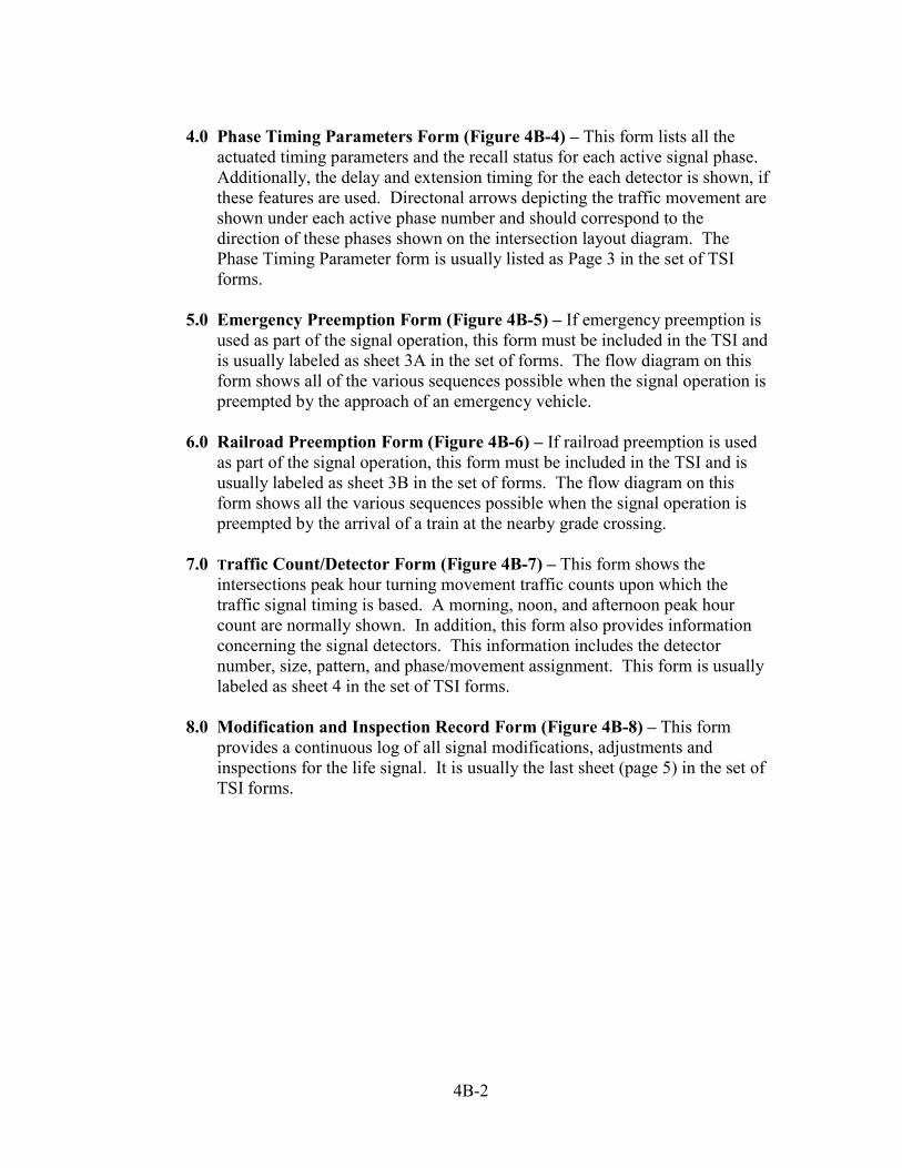
4.0 Phase Timing Parameters Form (Figure 4B-4) – This form lists all the
actuated timing parameters and the recall status for each active signal phase. Additionally, the delay and extension timing for the each detector is shown, if these features are used. Directonal arrows depicting the traffic movement are shown under each active phase number and should correspond to the direction of these phases shown on the intersection layout diagram. The Phase Timing Parameter form is usually listed as Page 3 in the set of TSI forms.
5.0 Emergency Preemption Form (Figure 4B-5) – If emergency preemption is
used as part of the signal operation, this form must be included in the TSI and is usually labeled as sheet 3A in the set of forms. The flow diagram on this form shows all of the various sequences possible when the signal operation is preempted by the approach of an emergency vehicle.
6.0 Railroad Preemption Form (Figure 4B-6) – If railroad preemption is used
as part of the signal operation, this form must be included in the TSI and is usually labeled as sheet 3B in the set of forms. The flow diagram on this form shows all the various sequences possible when the signal operation is preempted by the arrival of a train at the nearby grade crossing.
7.0 Traffic Count/Detector Form (Figure 4B-7) – This form shows the
intersections peak hour turning movement traffic counts upon which the traffic signal timing is based. A morning, noon, and afternoon peak hour count are normally shown. In addition, this form also provides information concerning the signal detectors. This information includes the detector number, size, pattern, and phase/movement assignment. This form is usually labeled as sheet 4 in the set of TSI forms.
8.0 Modification and Inspection Record Form (Figure 4B-8) – This form
provides a continuous log of all signal modifications, adjustments and inspections for the life signal. It is usually the last sheet (page 5) in the set of TSI forms.
4B-2
TRAFFIC SIGNAL INVENTORY TSI NO. LOUISIANA DEPARTMENT OF TRANSPORTATION AND DEVELOPMENT/ TRAFFIC SECTION District 07 SHEET: 1 OF
INTERSECTION:CITY: PARISH: INSTALLATION DATE:
TYPE SIGNAL: LAST REVISION DATE:
PHASES Φ2 + Φ5 Φ2 + Φ6 Φ1 + Φ6 Φ4 + Φ8 FLINTERVALS 1 2 3 4 5 6 7 8 9 10 11 12 13 14 15 16 17 18
1 G G G G Y R R Y
2 G G G G Y R R Y
3 G G G G/G Y/Y R R Y
4 G/G G/Y G G Y R R Y
5 G G G G Y R R Y
6 G G G G Y R R Y
7 R/G R/Y R G Y R R
8 R G Y R R
9 R G Y R R
10 R/G R/Y R G Y R R
111213141516
TIME SEC 5.9 5.0 2.3 19.7 5.0 1.2 7.8 5.0 2.1 19.9 5.0 1.1 Offset =FO SEC 53 0 14 41 secYP SEC
PLAN = 1 CYCLE LENGTH = 80 TIMES OF OPERATION = 2200-2400 Hrs., Weekdays, 1000-2000 Hrs. Sunday
TIME SEC 5.9 5.0 2.3 43.7 5.0 1.2 5.8 5.0 2.1 22.9 5.0 1.1 Offset =FO SEC 54 0 12 42 secYP SEC
PLAN = 3 CYCLE LENGTH = 105 TIMES OF OPERATION = 0630-1000 Hrs., Weekdays, 0900-2000 Hrs. SaturdayTIME SEC 6.9 5.0 2.3 36.7 5.0 1.2 6.8 5.0 2.1 32.9 5.0 1.1 Offset =
FO SEC 66 0 13 53 secYP SEC
PLAN = 4 CYCLE LENGTH = 110 TIMES OF OPERATION = 1000-1500 Hrs. WeekdsaysTIME SEC 5.9 5.0 2.3 43.7 5.0 1.2 7.8 5.0 2.1 25.9 5.0 1.1 Offset =FO SEC 59 0 14 47 sec
YP SEC
PLAN = 5 CYCLE LENGTH = 110 TIMES OF OPERATION = 1500-1900 Hrs. WeedaysTIME SEC Offset =FO SEC secYP SEC
PLAN = CYCLE LENGTH = TIMES OF OPERATION =
Φ2 + Φ5 Φ2 + Φ6 Φ1 + Φ6 Φ4 + Φ8OLA
OLBSIGNAL WARRANTS: 1,7 MAINTAINED BY: LA DOTD CONTROLLER MANUF: Matel SYSTEM #:MASTER/ SLAVE: Slave MASTER AT TSI #: 501 COORDINATED WITH TSI #'S: 501 SYSTEM #:
FIGURE 4B-1
63
18
97
101
Fully Actuated, TBC
Em
erge
ncy
Ho
urs
of
Fla
shin
g O
per
atio
n:
5005
Main St. (US 90) @ Minor St.Sulphur Calcasieu 8-5-02
SIG
NA
L F
AC
ES
PH
AS
ING
SE
QU
EN
CE
TRAFFIC SIGNAL INVENTORY TSI NO. LOUISIANA DEPARTMENT OF TRANSPORTATION AND DEVELOPMENT/ TRAFFIC SECTION SHEET: 1A OF
SUPPLEMENTAL PHASING & TIMING
PHASES Φ1 + Φ6 Φ2 + Φ6 Φ2 + Φ5 Φ4 + Φ8 FLINTERVALS 1 2 3 4 5 6 7 8 9 10 11 12 13 14 15 16 17 18
1 G G G G Y R R Y
2 G G G G Y R R Y
3 G/G G/Y G G Y R R Y
4 G G G G/G Y/Y R R Y
5 G G G G Y R R Y
6 G G G G Y R R Y
7 R/G R/Y R G Y R R
8 R G Y R R
9 R G Y R R
10 R/G R/Y R G Y R R
111213141516
TIME SEC 5.9 5.0 2.1 24.9 5.0 1.2 5.8 5.0 2.3 31.7 5.0 1.1 Offset =FO SEC 63 0 12 51 secYP SEC
PLAN = 2 CYCLE LENGTH = 95 TIMES OF OPERATION = 0500-0630,1900-2200,Weekdays,0730-0900,2000-2400 Sat.
TIME SEC Offset =FO SEC secYP SEC
PLAN = CYCLE LENGTH = TIMES OF OPERATION =
TIME SEC Offset =FO SEC secYP SEC
PLAN = CYCLE LENGTH = TIMES OF OPERATION =
TIME SEC Offset =FO SEC secYP SEC
PLAN = CYCLE LENGTH = TIMES OF OPERATION =
TIME SEC Offset =FO SEC secYP SEC
PLAN = CYCLE LENGTH = TIMES OF OPERATION =
Φ1 + Φ6 Φ2 + Φ6 Φ2 + Φ5 Φ4 + Φ8OLA
OLB
FIGURE 4B-2
34
5500
Em
erge
ncy
Ho
urs
of
Fla
shin
g O
per
atio
n:
SIG
NA
L F
AC
ES
PH
AS
ING
SE
QU
EN
CE
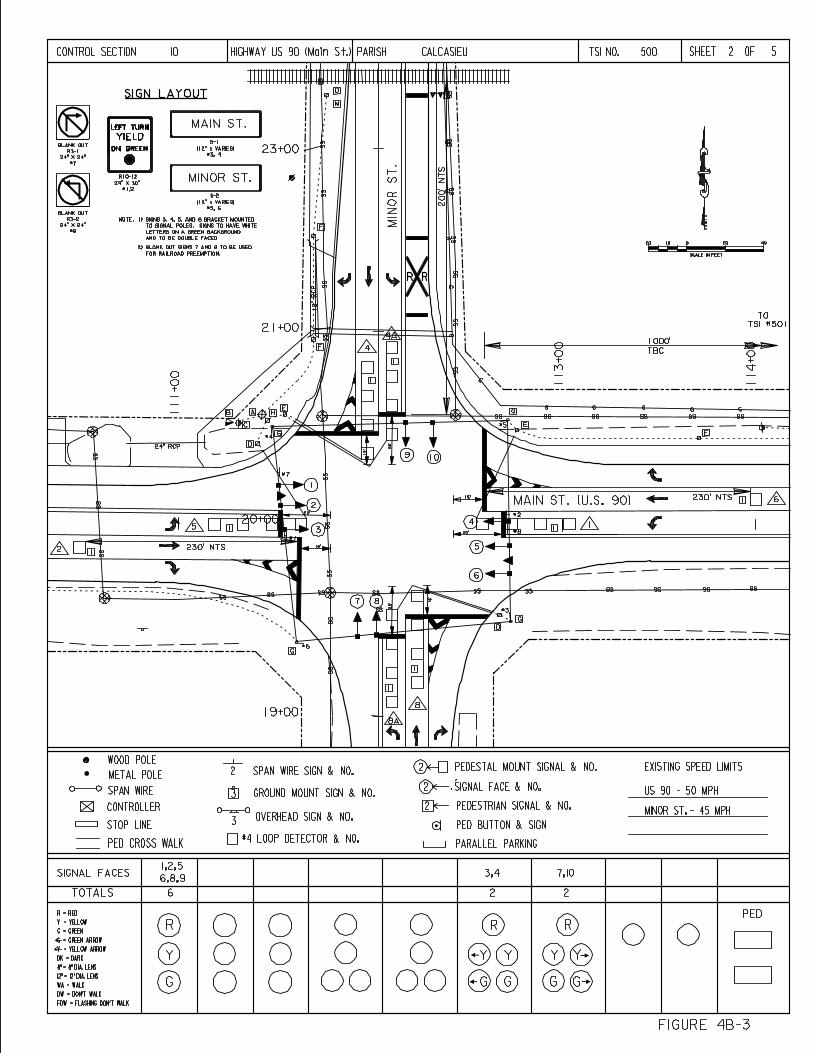
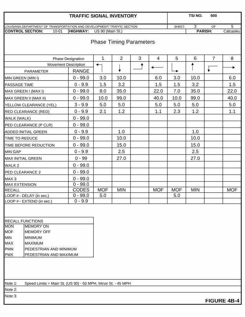
TRAFFIC SIGNAL INVENTORY TSI NO. 500
LOUISIANA DEPARTMENT OF TRANSPORTATION AND DEVELOPMENT/ TRAFFIC SECTION SHEET: 3 OF 5CONTROL SECTION: 10-01 HIGHWAY: Calcasieu
Phase Timing Parameters
Phase Designation 1 2 3 4 5 6 7 8Movement Description
PARAMETER RANGEMIN GREEN (MIN I) 0 - 99.0 3.0 10.0 6.0 3.0 10.0 6.0PASSAGE TIME 0 - 9.9 1.5 3.2 1.5 1.5 3.2 1.5MAX GREEN I (MAX I) 0 - 99.0 8.0 35.0 22.0 7.0 35.0 22.0MAX GREEN II (MAX II) 0 - 99.0 10.0 99.0 40.0 10.0 99.0 40.0YELLOW CLEARANCE (YEL) 3 - 9.9 5.0 5.0 5.0 5.0 5.0 5.0RED CLEARANCE (RED) 0 - 9.9 2.1 1.2 1.1 2.3 1.2 1.1WALK (WALK) 0 - 99.0PED CLEARANCE (P CLR) 0 - 99.0ADDED INITIAL GREEN 0 - 9.9 1.0 1.0TIME TO REDUCE 0 - 99.0 10.0 10.0TIME BEFORE REDUCTION 0 - 99.0 15.0 15.0MIN GAP 0 - 9.9 2.5 2.5MAX INITIAL GREEN 0 - 99 27.0 27.0WALK 2 0 - 99.0PED CLEARANCE 2 0 - 99.0MAX 3 0 - 99.0MAX EXTENSION 0 - 99.0RECALL CODES MOF MIN MOF MOF MIN MOFLOOP # - DELAY (in sec.) 0 - 99.0 5.0 5.0LOOP # - EXTEND (in sec.) 0 - 9.9
RECALL FUNCTIONSMON MEMORY ONMOF MEMORY OFF
MIN MINIMUMMAX MAXIMUM
PMN PEDESTRIAN AND MINIMUMPMX PEDESTRIAN AND MAXIMUM
Note 1: Speed Limits = Main St. (US 90) - 50 MPH, Minor St. - 45 MPH
Note 2:
Note 3:FIGURE 4B-4
PARISH:US 90 (Main St.)
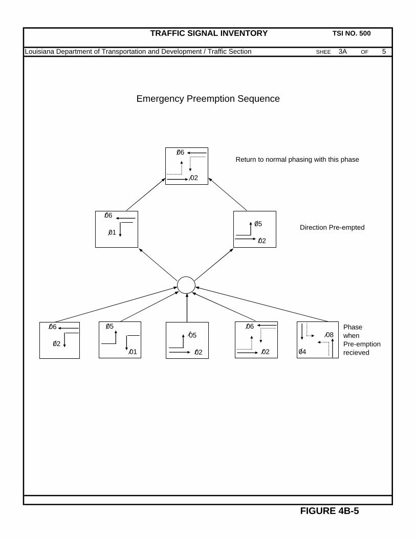
TRAFFIC SIGNAL INVENTORY TSI NO. 500
Louisiana Department of Transportation and Development / Traffic Section SHEET: 3A OF 5
Emergency Preemption Sequence
Return to normal phasing with this phase
Direction Pre-empted
FIGURE 4B-5
PhasewhenPre-emption recieved
06
02
06
01
05
02
06
02
05
01
05
02
06
02
08
04
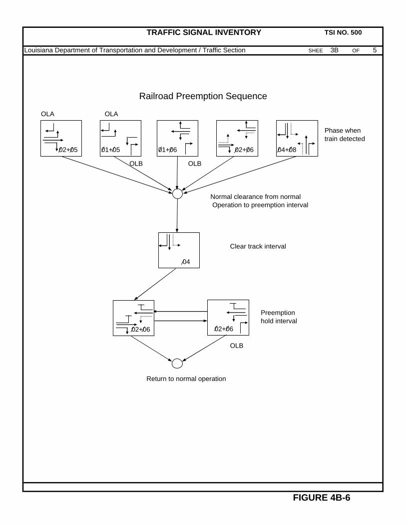
TRAFFIC SIGNAL INVENTORY TSI NO. 500
Louisiana Department of Transportation and Development / Traffic Section SHEET: 3B OF 5
Railroad Preemption Sequence
OLA OLA
Phase whentrain detected
OLB OLB
Normal clearance from normalOperation to preemption interval
Clear track interval
OLB
Return to normal operation
FIGURE 4B-6
Preemptionhold interval
02+05
04
02+06
02+06
01+05
01+06 02+06
04+08
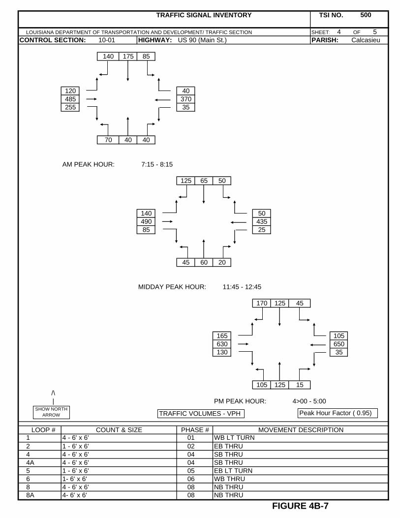
TRAFFIC SIGNAL INVENTORY TSI NO.
LOUISIANA DEPARTMENT OF TRANSPORTATION AND DEVELOPMENT/ TRAFFIC SECTION SHEET: 4 OF 5CONTROL SECTION: HIGHWAY: PARISH:
140 175 85
120 40485 370255 35
70 40 40
AM PEAK HOUR: 7:15 - 8:15
125 65 50
140 50490 43585 25
45 60 20
MIDDAY PEAK HOUR: 11:45 - 12:45
170 125 45
165 105630 650130 35
105 125 15 /\ | PM PEAK HOUR: 4>00 - 5:00
LOOP # COUNT & SIZE PHASE # MOVEMENT DESCRIPTION
FIGURE 4B-7
US 90 (Main St.)10-01
500
Calcasieu
1244A5688A
4 - 6' x 6'1 - 6' x 6'4 - 6' x 6'4 - 6' x 6'1 - 6' x 6'1- 6' x 6'4 - 6' x 6'4- 6' x 6'
01 02 04 04 05 06 08 08
WB LT TURNEB THRUSB THRUSB THRUEB LT TURNWB THRUNB THRUNB THRU
TRAFFIC VOLUMES - VPHSHOW NORTH
ARROW Peak Hour Factor ( 0.95) )
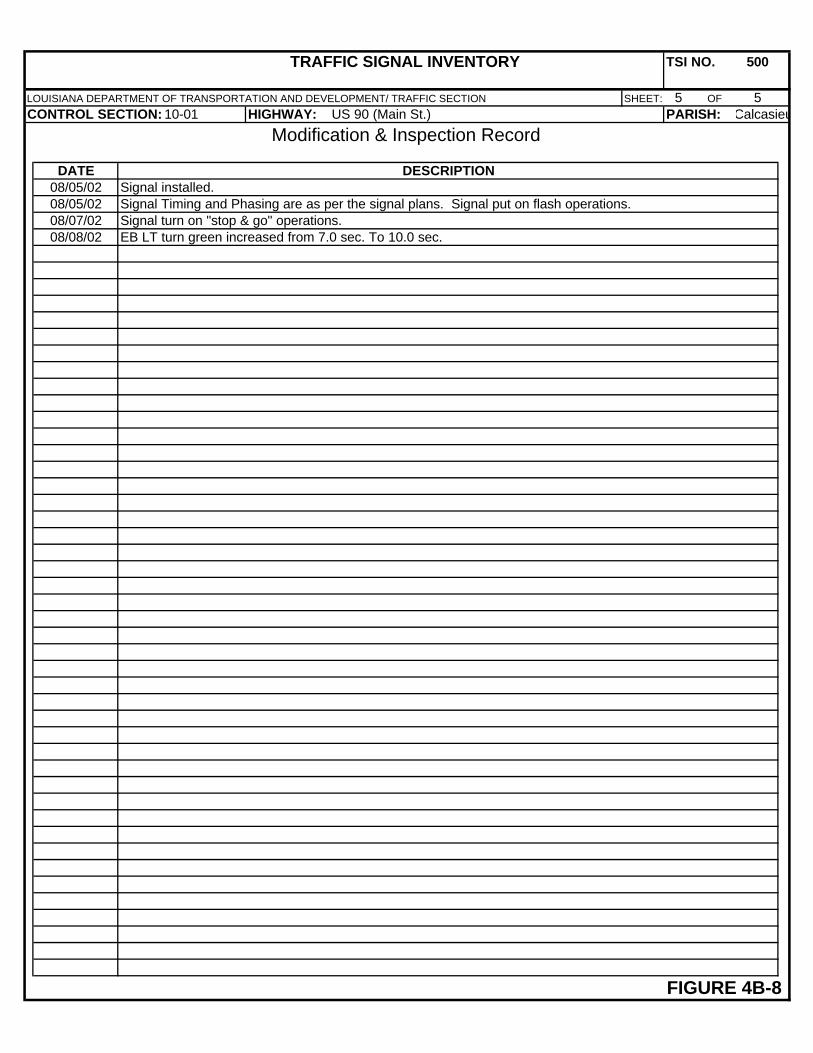
TRAFFIC SIGNAL INVENTORY TSI NO. 500
LOUISIANA DEPARTMENT OF TRANSPORTATION AND DEVELOPMENT/ TRAFFIC SECTION SHEET: 5 OF 5CONTROL SECTION: HIGHWAY: PARISH:
Modification & Inspection Record
DATE DESCRIPTION08/05/0208/05/0208/07/0208/08/02
FIGURE 4B-8
Signal turn on "stop & go" operations.EB LT turn green increased from 7.0 sec. To 10.0 sec.
US 90 (Main St.)10-01
Signal installed.Signal Timing and Phasing are as per the signal plans. Signal put on flash operations.
Calcasieu
BIBLIOGRAPHY
Butzer, George L. and Pusey, Raymond S., Chapter 13, “Traffic Control Signals”, ITE, Traffic Engineering Handbook, 5th Edition, Washington, D.C.’ 1999. ITE, Traffic Detector Handbook, 2nd Edition, Institute of Transportation Engineers, Washington D.C.
Kell, James H., and Fullerton, Iris, ITE Manual of Traffic Signal Design, 2nd Edition, Prentice Hall, 1991.
Louisiana Department of Transportation and Development (LA DOTD), Engineering Directive and Standards Manual (EDSM) Vol. 6 Traffic Operations.
Louisiana Department of Transportation and Development (LA DOTD), Louisiana Standard Specifications for Roads and Bridges, 2000 Edition.
Louisiana Department of Transportation and Development (LADOTD), Schedule Of Pay Items, 2000 Standard Specifications (English Version), April, 2001. Louisiana Department of Transportation and Development (LADOTD) Traffic Signal and Installation Detail Standard Plans.
Northwestern University, Traffic Institute, Railroad Grade Crossing Workshop Notebook, Evanston, Illinois, January, 1999.
Northwestern University, Traffic Institute, Traffic Actuated Control Workshop Notebook, Evanston, Illinois, January, 1999.
Northwestern University, Traffic Institute, Traffic Signal Workshop Notebook, Evanston, Illinois, September, 1994.
Seyfried, Robert K., Northwestern University, Traffic Institute, “Timing of Traffic Signal Preemption at Intersections near Highway-Railroad Grade Crossings,” paper presented at Institute of Transportation, annual meeting, Chicago, Illinois, August 2001.
Transportation Research Board, National Research Council, Highway Capacity Manual, Washington, D.C., 2000 U.S. Department of Transportation, Federal Highway Administration (FHWA), Manual of Uniform Traffic Control Devices, (MUTCD), Millennium Edition, Washington D.C., 2001.
U.S. Department of Transportation Federal Highway Administration (FHWA), Traffic Control Devices Handbook, Washington D.C., U.S. Government Printing Office, 1983.