Embed Size (px)
Citation preview
Cisco MRelease 1.1.3, Part Number 78-12899-01 Rev. B0, January 2002
C H A P T E R 7
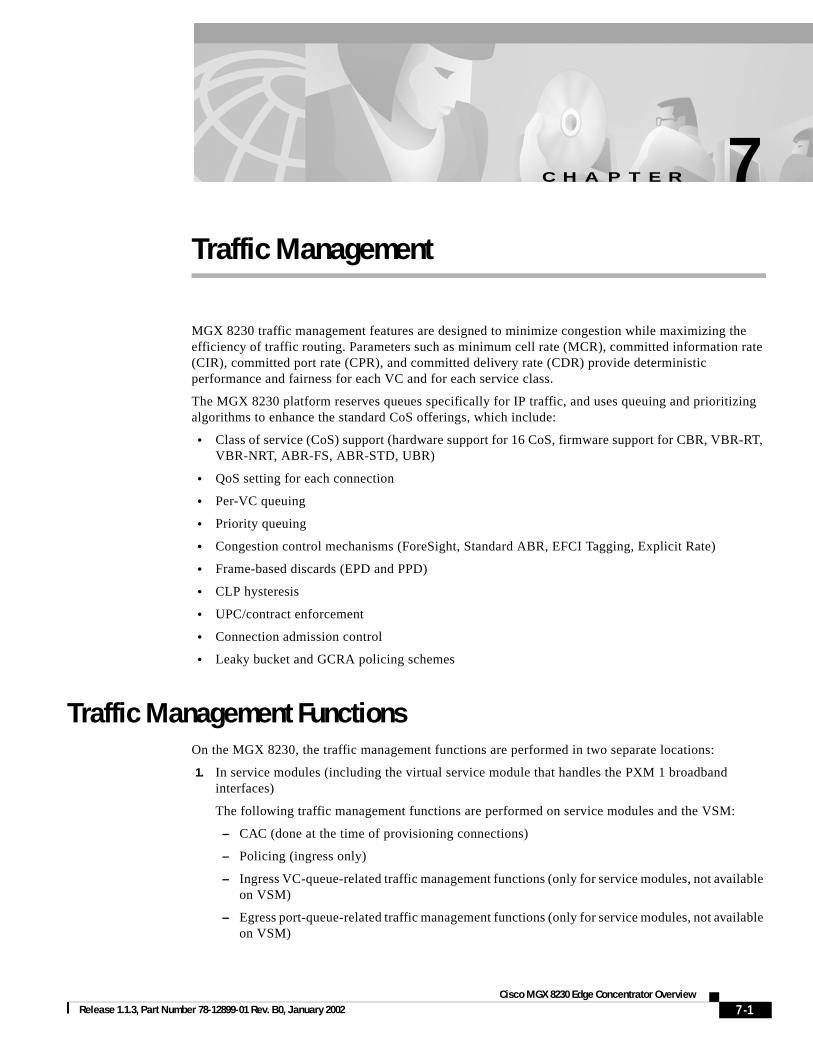
Traffic ManagementMGX 8230 traffic management features are designed to minimize congestion while maximizing the efficiency of traffic routing. Parameters such as minimum cell rate (MCR), committed information rate (CIR), committed port rate (CPR), and committed delivery rate (CDR) provide deterministic performance and fairness for each VC and for each service class.
The MGX 8230 platform reserves queues specifically for IP traffic, and uses queuing and prioritizing algorithms to enhance the standard CoS offerings, which include:
• Class of service (CoS) support (hardware support for 16 CoS, firmware support for CBR, VBR-RT, VBR-NRT, ABR-FS, ABR-STD, UBR)
• QoS setting for each connection
• Per-VC queuing
• Priority queuing
• Congestion control mechanisms (ForeSight, Standard ABR, EFCI Tagging, Explicit Rate)
• Frame-based discards (EPD and PPD)
• CLP hysteresis
• UPC/contract enforcement
• Connection admission control
• Leaky bucket and GCRA policing schemes
Traffic Management FunctionsOn the MGX 8230, the traffic management functions are performed in two separate locations:
1. In service modules (including the virtual service module that handles the PXM 1 broadband interfaces)
The following traffic management functions are performed on service modules and the VSM:
– CAC (done at the time of provisioning connections)
– Policing (ingress only)
– Ingress VC-queue-related traffic management functions (only for service modules, not available on VSM)
– Egress port-queue-related traffic management functions (only for service modules, not available on VSM)
7-1GX 8230 Edge Concentrator Overview
Chapter 7 Traffic ManagementTraffic Management Functions
2. Switch fabric's queue engine on PXM 1
The queue engine (QE) ASIC provides the traffic management functions related to VC queues, QoS queues, and interface queues. This is done for both directions of traffic. The PXM 1 card can have up to four physical lines. The user can split the line resources into multiple logical ports up to a maximum of 32. The switching fabric maps each of these logical ports defined on the PXM 1 lines to what is termed a virtual interface (VI). The switching fabric also maps each service module slot to a virtual interface.
Figure 7-1 reflects functional flow of data passing through the PXM 1 switch fabric and daughter card.
Figure 7-1 PXM Switch Fabric
Ingress traffic is defined as data flowing toward the switch fabric. Ingress data can come from either the service modules through the backplane or the PXM 1 uplink back card.
Egress traffic is defined as data flowing away from the switch fabric.
Ingress data from service modules arrives at the PXM 1 via the cell bus and hits the switch fabric, where the VC and Qbin queueing occurs. The destination of this traffic defines which VI queue it will be placed into. Ingress data from the PXM 1 will first be channeled through the uplink daughter card where policing will occur. The uplink ingress data will then pass through the switching fabric and the same VC, Qbin, and VI queuing will occur.
Figure 7-2 shows in detail the ingressl traffic flow. Figure 7-3 shows the Switch Module to Switch Fabrication arbitration. Figure 7-4 shows Egress Traffic Management.
4303
2
SMEgress port Qs
SMEgress port Qs
SMVCQs
Policing
SM to SM
SM to Uplink
PXM user portto any
broadband
PXM userport to SM
SM
Policing
RCMP(Policing)
VSM Port 1
CELLBUS
CELLBUS
VI QQB inVC Q
VCQs
Port 2VSM(no egress Qs)
7-2Cisco MGX 8230 Edge Concentrator Overview
Release 1.1.3, Part Number 78-12899-01 Rev. B0, January 2002
Chapter 7 Traffic ManagementTraffic Management Functions
Figure 7-2 Ingress Traffic Management
Figure 7-3 Service Module to Switch Fabric Arbitration
4303
3
Ports Policing
Round-robinQ servicing
VCQs
max
ForeSight
ABREPDPPD
CellBusQ
4303
4
FRSM
FRSM-HS
AUSM-8
PXM-Trk
PXM-UNI
RPM
CESM
CBC arbitration
VCQs
Anyto
any
Anyto
any
max
VIsQs
32
16
CoS Qs
16
CoS Qs
7-3Cisco MGX 8230 Edge Concentrator Overview
Release 1.1.3, Part Number 78-12899-01 Rev. B0, January 2002
Chapter 7 Traffic ManagementConfigurable Traffic Parameters
Figure 7-4 Egress Traffic Management
Configurable Traffic ParametersThere are four groups of traffic management parameters that are configured for each connection:
1. Policing Parameters are applied in service modules and the VSM (virtual service module). These are effective for the ingress traffic coming into the service modules/VSM. Following parameters are examples:
– AUSM/B
pcr
scr
ibs
mbs
ingrUpcFGCRAEnable
cdvt
scrPolicingEnable
– FRSM
cir
bc
be
4303
5
CoSQs
CellBusQ
CellBusQ
VIQs
SAR
max
max
CoSQs
7-4Cisco MGX 8230 Edge Concentrator Overview
Release 1.1.3, Part Number 78-12899-01 Rev. B0, January 2002
Chapter 7 Traffic ManagementConfigurable Traffic Parameters
ibs
– CESM
None used
– PXM 1-BBIF (Broadband Interface-VSM)
pcr
scr
cdvt
mbs
scrPolicingEnable
2. The second group of parameters controls the VC queue properties in the service modules. These parameters also apply to the ingress traffic only. Please note that this set of parameters does not apply to VSM since it does not have VC queuing capability. Examples of parameters include:
– AUSM/B
ingressQDepth
ingressClpHiThresh
ingressClpLoThresh
ingressEFCITHresh
Discard option
– FRSM
ingressQDepth
ingressQDEThresh
ingressQECNThresh
– CESM
None used
– PXM 1-BBIF (Broadband Interface-VSM)
None used
3. The third set of parameters controls the properties of VC queues and QoS queues in the PXM 1. These parameters are applicable to both directions of traffic. These parameters are not set on a per-connection basis. Rather, they are controlled/managed through customer-configurable service templates (not currently implemented). The concept of a service template allows customers to define a set of service classes by fine-tuning the VC queue and QoS queue parameters. These templates are configured once in the system. At the time of connection, provisioning each connection is associated with one of the classes through the “service type” MIB object. The queue parameters configured for that service type are then applied to that connection in the QE. Thus, a finite sets of queue parameter combinations are defined in the beginning. The user can choose one predefined set of parameter combinations for each connection to be provisioned.
Currently, the service templates are not implemented in the MGX 8230 platform. The VC queue parameters are currently defaulted as follows for all connections:
– VC Depth is set to 50 percent of maximum cell memory in QE
– ClpHiThreshold is set to 80 percent of VC Depth
– ClpLoThreshold is set to 60 percent of VC Depth
7-5Cisco MGX 8230 Edge Concentrator Overview
Release 1.1.3, Part Number 78-12899-01 Rev. B0, January 2002
Chapter 7 Traffic ManagementConnection Admission Control
– EfciThreshold is set to 30 percent of VC Depth
4. The fourth set of parameters selects the egress service queue type for the traffic leaving the system through service modules. This does not apply to Virtual Servide Module (VSM) because it does not have any egress service queues. Examples of these parameters include:
AUSM/B
– egressQDepth
– egressClpHiThresh
– egressClpLoThresh
– egressEFCIThresh
– egressQAlgorithm
FRSM
– egressQSelect
– egressQDEThresh
– egressQECNThresh
CESM
– Cdvt
– EgressQDepth
VSM
None used
Connection Admission ControlConnection Admission Control (CAC) is performed on-port in the ingress and egress directions. Port overbooking is optionally supported on both the FRSM and the AUSM/B. The CAC override function is configurable on a per-connection basis.
1. For AUSM/B, PXM 1, and FRSM, CAC admits a new connection if the following holds true:
• Σ (Ingress_ER x (%Ingress_Util)) <= Ingress port speed. One port
• Σ (Egress_ER x (%Egress_Util)) <= Egress port speed. One port
• Overbooking = 1/(%ingress_Util)
2. For CAC on FRSM-8T1E1
Ingress (when CAC override is off or CAC is enabled):
• sum of (CIR * chanIngrPercentUtil) of all channels on the port < = port speed
Egress:
• sum of (chanEgrSrvRate * chanEgrPercentUtil) of all channels on the port < = port speed
When CAC overide is ON or CAC is disabled, the load is still cumulated on the port for a channel, but it is always admitted if CIR/chanEgrSrvRate is less than port speed.
3. For CAC on AUSM/B-8T1E1
For the ingress rate, ingrUpcPCR01 is used for CBR/VBR and UBR, and foresightMIR is used for ABR. For the egress side, the rate used is ausmChanEgrSrvRate.
7-6Cisco MGX 8230 Edge Concentrator Overview
Release 1.1.3, Part Number 78-12899-01 Rev. B0, January 2002
Chapter 7 Traffic ManagementPolicing
CAC Algorithms:
• Ingress side
– if Σ(ingrRate * ingr pct util) > PORT_RATE, CAC fail.
– if Σ(ingrRate * ingr pct util > Rate available for that controller, CAC fail.
• Egress side
– If Σ(egrRate * egr pct util)> PORT_RATE, CAC fail.
– if Σ(egrRate * egr pct util)> Rate avail. for that ctrlr, CAC fail.
• For the rest of the cases, CAC passes.
– In case ausmChanOvrSubOvrRide is enabled, even though CAC fails, connection addition goes through.
PolicingThe edge concentrator complies with the UPC policing standards as defined by the ATM Forum UNI 3.1 Specifications. The following are the traffic descriptors configurable on a per-connection basis:
• PCR, SCR, MCR, BT, CDVT
• Policing algorithm can be enforced on the following cell types:
– User
– Resource management
– CLP0
– CLP1
– Any combination of the cell types (User, RM, CLP0, CLP1)
• Single and dual leaky bucket policing schemes
• Configurable actions for nonconforming cells
– Keep count
– Tag nonconforming cells
– Tag and discard low-priority cells
– Frame-based discards (early packet and partial packet discard)
– Tag and discard all non-conforming cells
– CLP hysteresis
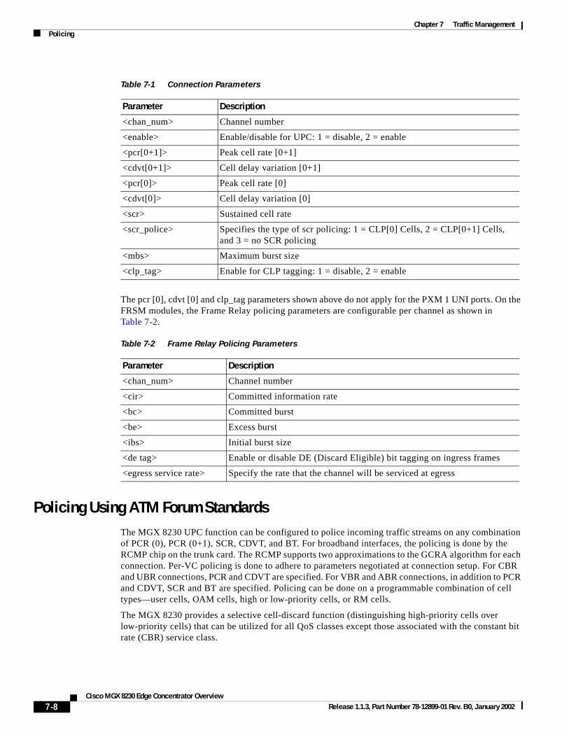
Configuring Traffic DescriptorsFor AUSM/B modules different bandwidth control parameters can be defined depending on the type of connection. For CBR and UBR connections, PCR and CDVT are specified. For VBR and ABR connections, and PCR and CDVT, SCR and BT are specified. Table 7-1shows the different parameters that can be defined during connection setup. It also indicates that UPC can be enabled/disabled on a per connection basis.
7-7Cisco MGX 8230 Edge Concentrator Overview
Release 1.1.3, Part Number 78-12899-01 Rev. B0, January 2002
Chapter 7 Traffic ManagementPolicing
The pcr [0], cdvt [0] and clp_tag parameters shown above do not apply for the PXM 1 UNI ports. On the FRSM modules, the Frame Relay policing parameters are configurable per channel as shown in Table 7-2.
Policing Using ATM Forum StandardsThe MGX 8230 UPC function can be configured to police incoming traffic streams on any combination of PCR (0), PCR (0+1), SCR, CDVT, and BT. For broadband interfaces, the policing is done by the RCMP chip on the trunk card. The RCMP supports two approximations to the GCRA algorithm for each connection. Per-VC policing is done to adhere to parameters negotiated at connection setup. For CBR and UBR connections, PCR and CDVT are specified. For VBR and ABR connections, in addition to PCR and CDVT, SCR and BT are specified. Policing can be done on a programmable combination of cell types—user cells, OAM cells, high or low-priority cells, or RM cells.
The MGX 8230 provides a selective cell-discard function (distinguishing high-priority cells over low-priority cells) that can be utilized for all QoS classes except those associated with the constant bit rate (CBR) service class.
Table 7-1 Connection Parameters
Parameter Description
<chan_num> Channel number
<enable> Enable/disable for UPC: 1 = disable, 2 = enable
<pcr[0+1]> Peak cell rate [0+1]
<cdvt[0+1]> Cell delay variation [0+1]
<pcr[0]> Peak cell rate [0]
<cdvt[0]> Cell delay variation [0]
<scr> Sustained cell rate
<scr_police> Specifies the type of scr policing: 1 = CLP[0] Cells, 2 = CLP[0+1] Cells, and 3 = no SCR policing
<mbs> Maximum burst size
<clp_tag> Enable for CLP tagging: 1 = disable, 2 = enable
Table 7-2 Frame Relay Policing Parameters
Parameter Description
<chan_num> Channel number
<cir> Committed information rate
<bc> Committed burst
<be> Excess burst
<ibs> Initial burst size
<de tag> Enable or disable DE (Discard Eligible) bit tagging on ingress frames
<egress service rate> Specify the rate that the channel will be serviced at egress
7-8Cisco MGX 8230 Edge Concentrator Overview
Release 1.1.3, Part Number 78-12899-01 Rev. B0, January 2002
Chapter 7 Traffic ManagementPolicing
During connection setup, the action taken on a non-conforming cell can be programmed on a per-VC basis.
• Keep count
• Tag change to low priority
• Tag and discard low-priority cells
• Discard all nonconforming cells
For CBR and UBR connections, only one policing instance (GCRA-1) is needed to check for PCR and CDVT conformance. For VBR and ABR connections, one policing instance (GCRA-1) is needed to check for PCR, CDVT conformance, and another instance (GCRA-2) for SCR, BT conformance. Frame discard features are supported in the queue engine.
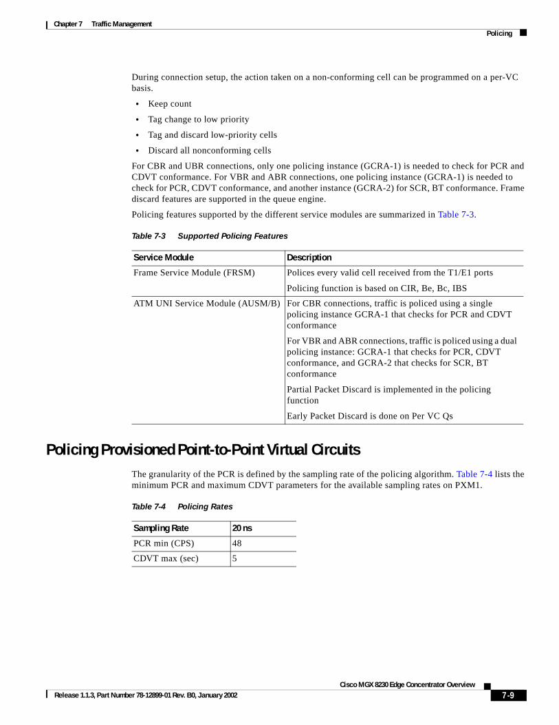
Policing features supported by the different service modules are summarized in Table 7-3.
Policing Provisioned Point-to-Point Virtual CircuitsThe granularity of the PCR is defined by the sampling rate of the policing algorithm. Table 7-4 lists the minimum PCR and maximum CDVT parameters for the available sampling rates on PXM1.
Table 7-3 Supported Policing Features
Service Module Description
Frame Service Module (FRSM) Polices every valid cell received from the T1/E1 ports
Policing function is based on CIR, Be, Bc, IBS
ATM UNI Service Module (AUSM/B) For CBR connections, traffic is policed using a single policing instance GCRA-1 that checks for PCR and CDVT conformance
For VBR and ABR connections, traffic is policed using a dual policing instance: GCRA-1 that checks for PCR, CDVT conformance, and GCRA-2 that checks for SCR, BT conformance
Partial Packet Discard is implemented in the policing function
Early Packet Discard is done on Per VC Qs
Table 7-4 Policing Rates
Sampling Rate 20 ns
PCR min (CPS) 48
CDVT max (sec) 5
7-9Cisco MGX 8230 Edge Concentrator Overview
Release 1.1.3, Part Number 78-12899-01 Rev. B0, January 2002
Chapter 7 Traffic ManagementService Module Policing Function
Service Module Policing FunctionThis section describes the policing functions for the various service modules.
Frame Service Module (FRSM)The policing function for the FRSM cards is based on a dual leaky bucket operation. The first bucket checks for compliance with the burst Bc, and the second bucket checks for compliance with the burst Be. The policing function in the FRSM measures the incoming traffic average rate over a period “T.” It then decides if the traffic should be
• forwarded
• tagged and forwarded
• discarded
• DE = 0 traffic conforming to CIR is forwarded
• DE = 0 traffic nonconforming to CIR but conforming to EIR is tagged and forwarded
• DE = 0 traffic nonconforming to CIR and EIR is discarded
• DE = 1 traffic conforming to EIR is forwarded
• DE = 1 traffic nonconforming to EIR is discarded
The policing mechanism differs slightly between the lower speed FRSM cards (FRSM-8T1/8E1/8-T1-C/8-E1-C/HS1/B) and the higher speed FRSM cards (FRSM-HS2/2CT3/2T3E3).
The overall dual leaky bucket algorithm is used for both types of cards, but there are a few differences regarding limits, the credit scheme, and the IBS function as described below.
• Increased limits—The maximum permissible burst size is increased from 65535 bytes to 2,097,151 bytes.
• Credit scheme—On the higher speed FRSMs, credit is given to a connection based on the actual time and the time elapsed since the arrival of the last frame. The bucket leaks by a certain amount, and this amount is the “credit” for the connection. The first bucket is of size Bc and leaks at the rate of CIR; the second bucket is of size Be and leaks at the rate of EIR. Every time a frame is received, the policing function determines the amount by which the bucket should leak. This is done by finding the difference between the current time and the time at which the last compliant frame was received. The credit for a connection is proportional to the time difference and the rate of the connection (either CIR or EIR depending on the bucket). A frame is compliant to that bucket if the contents of the bucket do not overflow. Finally, the policing function increases the contents of the bucket by the number of bytes in the received frame. The size of the first bucket is Bc, and the size of the second bucket is Be. The policing function timestamps the connection with the current time if the frame was compliant.
• On the lower speed FRSMs, credit is given to a connection every 10 ms.
• Initial burst size (IBS): On the higher speed FRSMs, the IBS function is not linked to policing. A connection must be silent for a period of time equal to QIR timeout to qualify for IBS. The frame is flagged for IBS and queued as normal through per-VC queuing. When it is scheduled to be sent out on the cell bus, the connection temporarily has its Instantaneous Rate (IR) and priority increased until it transmits IBS number of bytes. Then the IR and priority of the connection are reset to their original values.
For the lower speed FRSMs, if the amount of credit accumulated is less than the IBS value (which is user configurable), then the frame was marked for a separate IBS queue.
7-10Cisco MGX 8230 Edge Concentrator Overview
Release 1.1.3, Part Number 78-12899-01 Rev. B0, January 2002
Chapter 7 Traffic ManagementService Module Policing Function
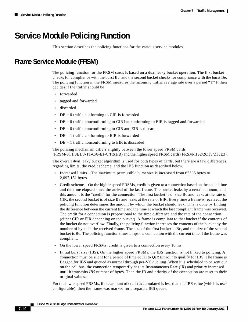
Figure 7-5 shows the ingress cell flow on the FRSMs.
Figure 7-5 Ingress Cell Flow
For FRSM modules, the F-GCRA feature is not available at the UPC policing point.
ATM Service Module (AUSM/B)The UPC in AUSM/B can be configured to run either a frame-based generic cell rate algorithm (FGCRA) or the GCRA defined in ATM UNI3.0. In case of FGCRA, at the arrival of the first cell of the frame, the bucket depth is compared with a limit parameter (for example: L1). If the first cell is noncompliant, then all the remaining cells in the frame will be treated as noncompliant. If the first cell is compliant, then remaining cells will be compliant if the depth of the bucket upon cell arrival is less than or equal to a limit parameter (for example: L2).
Once the cell has passed through UPC, it will be queued onto the ingress queue after the following checks:
1. Queue is full (the cell is then discarded)
2. CLP High Threshold is exceeded (the CLP set cells will therefore be discarded)
3. CLP hysteresis is set (once cells reach CLP threshold, they will be dropped until CLP low threshold is reached)
4. EPD/PPD discard is set (if the first cell of the frame exceeds EPD threshold, then all cells of that frame are discarded)
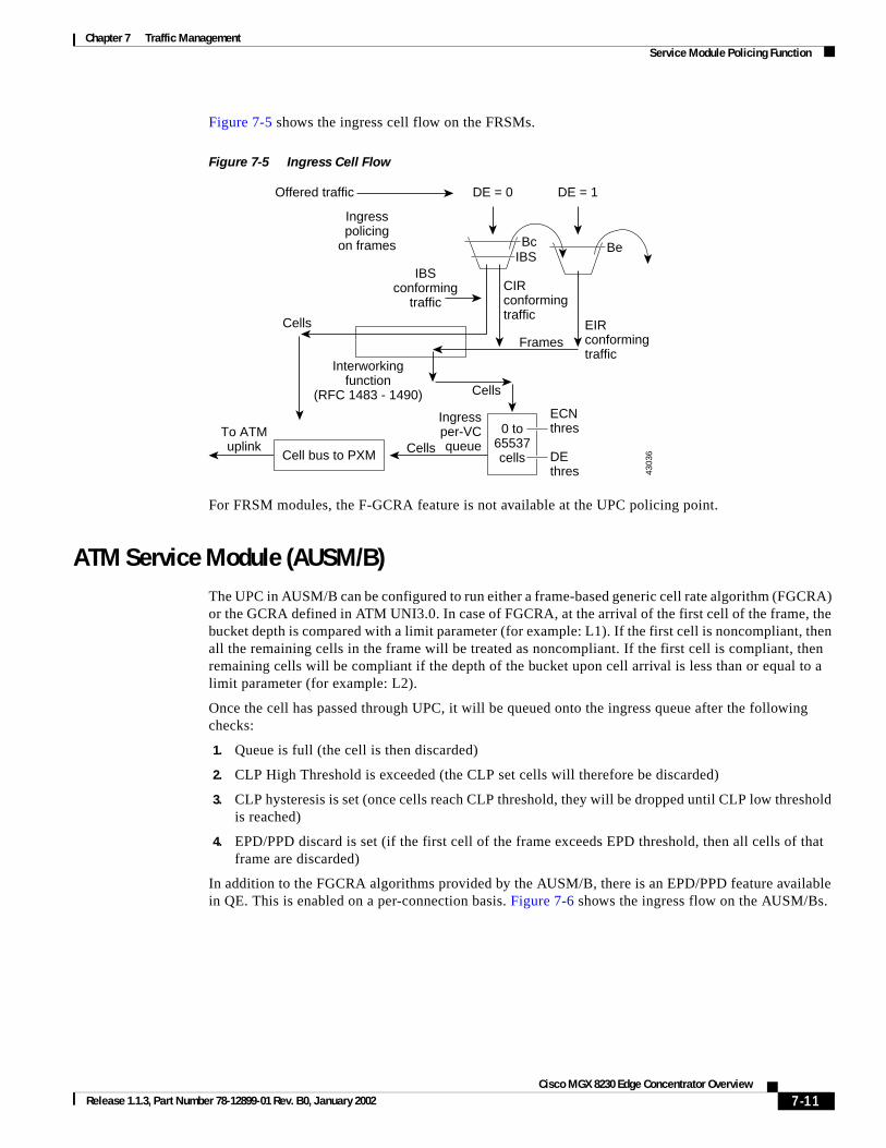
In addition to the FGCRA algorithms provided by the AUSM/B, there is an EPD/PPD feature available in QE. This is enabled on a per-connection basis. Figure 7-6 shows the ingress flow on the AUSM/Bs.
Be
4303
6
Offered traffic
Ingresspolicing
on frames
Cells
Cells
Ingressper-VCqueue
ECNthres
Interworkingfunction
(RFC 1483 - 1490)
IBSconforming
trafficCIRconformingtraffic
EIRconformingtraffic
Frames
Cells
DE = 0 DE = 1
Bc
Cell bus to PXM DEthres
0 to65537cells
To ATMuplink
IBS
7-11Cisco MGX 8230 Edge Concentrator Overview
Release 1.1.3, Part Number 78-12899-01 Rev. B0, January 2002
Chapter 7 Traffic ManagementService Module Policing Function
Figure 7-6 Ingress Flow on an AUSM/B
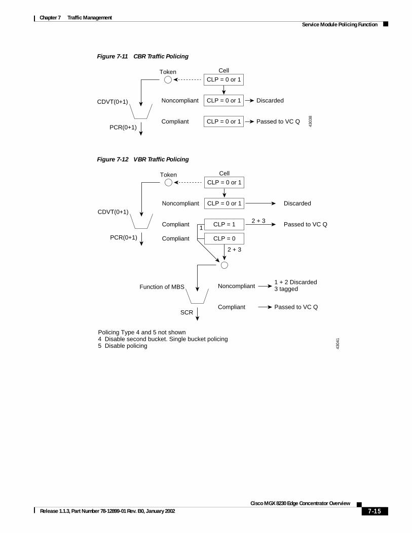
Figure 7-7 and Figure 7-8 show the policing for the different types of traffic.
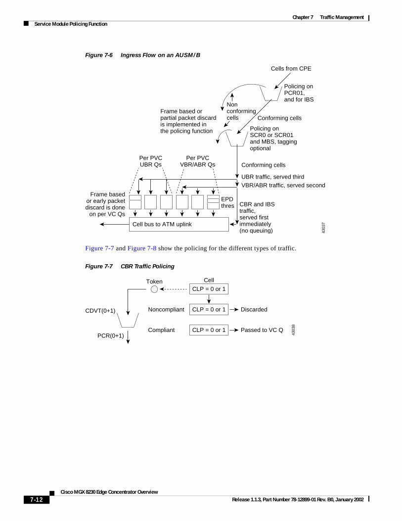
Figure 7-7 CBR Traffic Policing
4303
7
Frame basedor early packetdiscard is done
on per VC Qs
Per PVCUBR Qs
EPDthres CBR and IBS
traffic,served firstimmediately(no queuing)
UBR traffic, served third
Conforming cells
Conforming cells
Nonconformingcells
VBR/ABR traffic, served second
Per PVCVBR/ABR Qs
Cell bus to ATM uplink
Policing onSCR0 or SCR01and MBS, taggingoptional
Policing onPCR01,and for IBS
Cells from CPE
Frame based orpartial packet discardis implemented inthe policing function
4303
8CLP = 0 or 1
CLP = 0 or 1
CLP = 0 or 1
Noncompliant
Compliant
Discarded
Passed to VC Q
CellToken
CDVT(0+1)
PCR(0+1)
7-12Cisco MGX 8230 Edge Concentrator Overview
Release 1.1.3, Part Number 78-12899-01 Rev. B0, January 2002
Chapter 7 Traffic ManagementService Module Policing Function
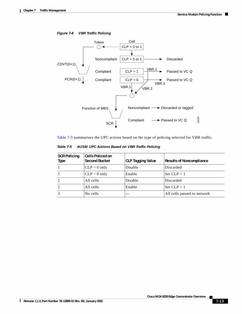
Figure 7-8 VBR Traffic Policing
Table 7-5 summarizes the UPC actions based on the type of policing selected for VBR traffic.
4303
9
CLP = 0 or 1
CLP = 0 or 1
CLP = 1
Noncompliant
Compliant
Discarded
Passed to VC Q
Noncompliant
Compliant
Discarded or tagged
Passed to VC Q
Cell
VBR.1
VBR.1
CLP = 0Compliant Passed to VC QVBR.3
VBR.2
Token
CDVT(0+1)
PCR(0+1)
Function of MBS
SCR
Table 7-5 AUSM UPC Actions Based on VBR Traffic Policing
SCR Policing Type
Cells Policed on Second Bucket CLP Tagging Value Results of Noncompliance
1 CLP = 0 only Disable Discarded
1 CLP = 0 only Enable Set CLP = 1
2 All cells Disable Discarded
2 All cells Enable Set CLP = 1
3 No cells — All cells passed to network
7-13Cisco MGX 8230 Edge Concentrator Overview
Release 1.1.3, Part Number 78-12899-01 Rev. B0, January 2002
Chapter 7 Traffic ManagementService Module Policing Function
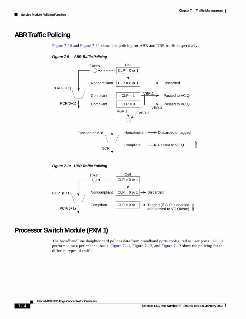
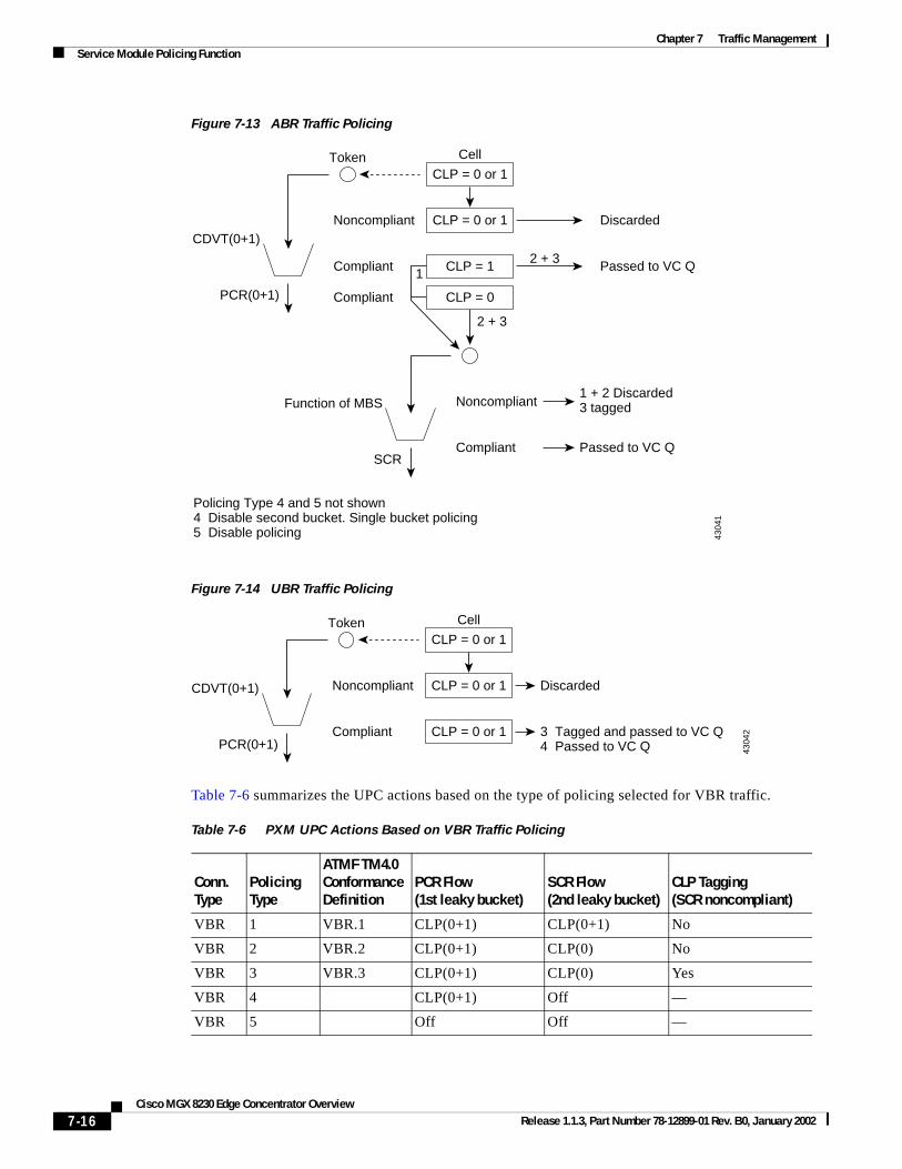
ABR Traffic PolicingFigure 7-10 and Figure 7-11 shows the policing for ABR and UBR traffic respectively.
Figure 7-9 ABR Traffic Policing
Figure 7-10 UBR Traffic Policing
Processor Switch Module (PXM 1)The broadband line daughter card polices data from broadband ports configured as user ports. UPC is performed on a per-channel basis. Figure 7-11, Figure 7-12, and Figure 7-13 show the policing for the different types of traffic.
4303
9
CLP = 0 or 1
CLP = 0 or 1
CLP = 1
Noncompliant
Compliant
Discarded
Passed to VC Q
Noncompliant
Compliant
Discarded or tagged
Passed to VC Q
Cell
VBR.1
VBR.1
CLP = 0Compliant Passed to VC QVBR.3
VBR.2
Token
CDVT(0+1)
PCR(0+1)
Function of MBS
SCR
4304
0
CLP = 0 or 1
CLP = 0 or 1
CLP = 0 or 1
Noncompliant
Compliant
Discarded
Tagged (if CLP is enabledand passed to VC Queue)
CellToken
CDVT(0+1)
PCR(0+1)
7-14Cisco MGX 8230 Edge Concentrator Overview
Release 1.1.3, Part Number 78-12899-01 Rev. B0, January 2002
Chapter 7 Traffic ManagementService Module Policing Function
Figure 7-11 CBR Traffic Policing
Figure 7-12 VBR Traffic Policing
4303
8
CLP = 0 or 1
CLP = 0 or 1
CLP = 0 or 1
Noncompliant
Compliant
Discarded
Passed to VC Q
CellToken
CDVT(0+1)
PCR(0+1)
4304
1
CLP = 0 or 1
CLP = 0 or 1
CLP = 1
Noncompliant
Compliant
Discarded
Passed to VC Q
Noncompliant
Compliant
1 + 2 Discarded3 tagged
Passed to VC Q
Cell
2 + 31
CLP = 0Compliant
2 + 3
Token
CDVT(0+1)
PCR(0+1)
Function of MBS
Policing Type 4 and 5 not shown4 Disable second bucket. Single bucket policing5 Disable policing
SCR
7-15Cisco MGX 8230 Edge Concentrator Overview
Release 1.1.3, Part Number 78-12899-01 Rev. B0, January 2002
Chapter 7 Traffic ManagementService Module Policing Function
Figure 7-13 ABR Traffic Policing
Figure 7-14 UBR Traffic Policing
Table 7-6 summarizes the UPC actions based on the type of policing selected for VBR traffic.
4304
1
CLP = 0 or 1
CLP = 0 or 1
CLP = 1
Noncompliant
Compliant
Discarded
Passed to VC Q
Noncompliant
Compliant
1 + 2 Discarded3 tagged
Passed to VC Q
Cell
2 + 31
CLP = 0Compliant
2 + 3
Token
CDVT(0+1)
PCR(0+1)
Function of MBS
Policing Type 4 and 5 not shown4 Disable second bucket. Single bucket policing5 Disable policing
SCR
4304
2
CLP = 0 or 1
CLP = 0 or 1
CLP = 0 or 1
Noncompliant
Compliant
Discarded
3 Tagged and passed to VC Q4 Passed to VC Q
CellToken
CDVT(0+1)
PCR(0+1)
Table 7-6 PXM UPC Actions Based on VBR Traffic Policing
Conn. Type
Policing Type
ATMF TM4.0 Conformance Definition
PCR Flow(1st leaky bucket)
SCR Flow(2nd leaky bucket)
CLP Tagging(SCR noncompliant)
VBR 1 VBR.1 CLP(0+1) CLP(0+1) No
VBR 2 VBR.2 CLP(0+1) CLP(0) No
VBR 3 VBR.3 CLP(0+1) CLP(0) Yes
VBR 4 CLP(0+1) Off —
VBR 5 Off Off —
7-16Cisco MGX 8230 Edge Concentrator Overview
Release 1.1.3, Part Number 78-12899-01 Rev. B0, January 2002
Chapter 7 Traffic ManagementService Module Policing Function
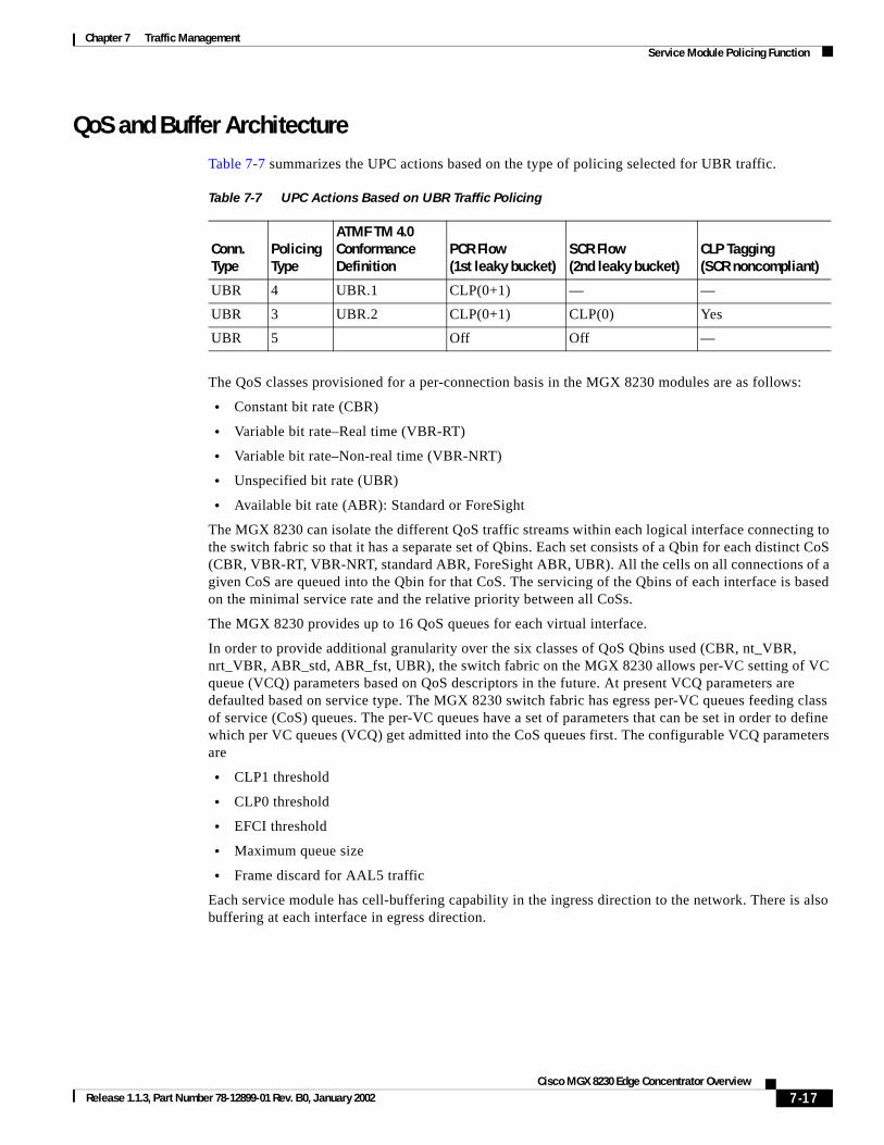
QoS and Buffer ArchitectureTable 7-7 summarizes the UPC actions based on the type of policing selected for UBR traffic.
The QoS classes provisioned for a per-connection basis in the MGX 8230 modules are as follows:
• Constant bit rate (CBR)
• Variable bit rate–Real time (VBR-RT)
• Variable bit rate–Non-real time (VBR-NRT)
• Unspecified bit rate (UBR)
• Available bit rate (ABR): Standard or ForeSight
The MGX 8230 can isolate the different QoS traffic streams within each logical interface connecting to the switch fabric so that it has a separate set of Qbins. Each set consists of a Qbin for each distinct CoS (CBR, VBR-RT, VBR-NRT, standard ABR, ForeSight ABR, UBR). All the cells on all connections of a given CoS are queued into the Qbin for that CoS. The servicing of the Qbins of each interface is based on the minimal service rate and the relative priority between all CoSs.
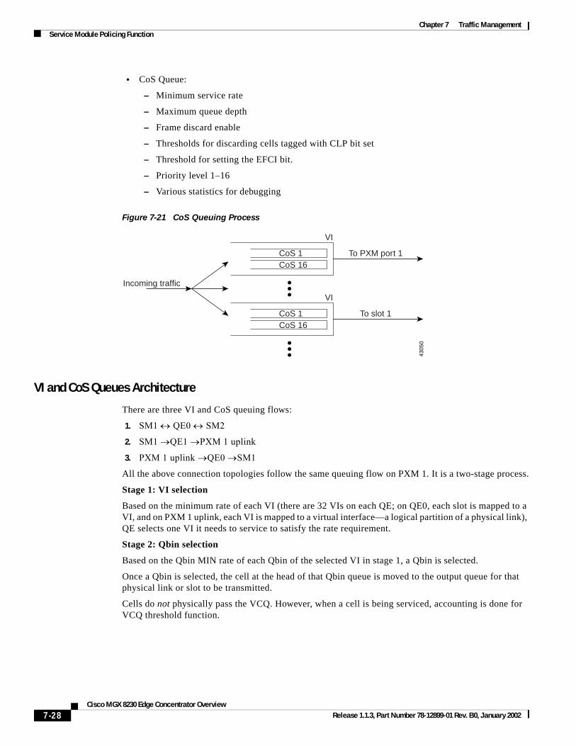
The MGX 8230 provides up to 16 QoS queues for each virtual interface.
In order to provide additional granularity over the six classes of QoS Qbins used (CBR, nt_VBR, nrt_VBR, ABR_std, ABR_fst, UBR), the switch fabric on the MGX 8230 allows per-VC setting of VC queue (VCQ) parameters based on QoS descriptors in the future. At present VCQ parameters are defaulted based on service type. The MGX 8230 switch fabric has egress per-VC queues feeding class of service (CoS) queues. The per-VC queues have a set of parameters that can be set in order to define which per VC queues (VCQ) get admitted into the CoS queues first. The configurable VCQ parameters are
• CLP1 threshold
• CLP0 threshold
• EFCI threshold
• Maximum queue size
• Frame discard for AAL5 traffic
Each service module has cell-buffering capability in the ingress direction to the network. There is also buffering at each interface in egress direction.
Table 7-7 UPC Actions Based on UBR Traffic Policing
Conn. Type
Policing Type
ATMF TM 4.0 Conformance Definition
PCR Flow(1st leaky bucket)
SCR Flow(2nd leaky bucket)
CLP Tagging(SCR noncompliant)
UBR 4 UBR.1 CLP(0+1) — —
UBR 3 UBR.2 CLP(0+1) CLP(0) Yes
UBR 5 Off Off —
7-17Cisco MGX 8230 Edge Concentrator Overview
Release 1.1.3, Part Number 78-12899-01 Rev. B0, January 2002
Chapter 7 Traffic ManagementService Module Policing Function
Frame Service Module (FRSM)For the FRSM cards the buffer size is as follows:
• Low-speed FRSMs
– For egress: Tx buffer size = 144 bytes
– For ingress: Rx buffer size = 144 bytes
• High-speed FRSMs
– For egress: Tx buffer size = 256 bytes
– For ingress: Rx buffer size = 256 bytes
Ingress Queuing
All conforming frames in a VC queue are serviced based on the VC’s configured CIR. The CIR measurement is done by monitoring committed burst, Bc, during a burst duration, Tc. If more than Bc bytes of traffic are received within the Tc interval, the arrival rate is considered to exceed CIR.
The per-VC queuing differs slightly for the high-speed FRSM cards and the lower speed FRSM cards.
High-speed FRSM Cards
This group includes the FRSM-HS2, FRSM-2CT3, and the FRSM-2T3E3. In the ingress direction, there are five different classes of service, CBR, rt-VBR, nrt-VBR, ABR, and UBR.
Lower Speed FRSM Cards
This group includes the FRSM-8T1/8E1/8T1-C/8E1-C/HS1/B cards. In the ingress direction, different classes of service are not supported for per-VC queuing.
7-18Cisco MGX 8230 Edge Concentrator Overview
Release 1.1.3, Part Number 78-12899-01 Rev. B0, January 2002
Chapter 7 Traffic ManagementService Module Policing Function
Figure 7-15 shows the per-VC queuing on the FRSM cards.
Figure 7-15 Per-VC Queuing on FRSM Cards
Egress Queuing
ATM-like CoS queues have been introduced on the high-speed FRSM cards (FRSM-HS2/2CT3/2T3E3). There are four data queues:
• High-priority queue
• VBR-RT queue
• VBR-NRT and ABR queue
• UBR queue
The lower speed FRSM cards (FRSM-8T1/8E1/8T1-C/8E1-C/HS1/B) have no ATM-like CoS egress queuing mechanism. These cards have two levels of priority for data traffic—a high-priority queue and a low-priority queue. Queue is determined based upon connection type. In case of two queues, high-priority and VBR-RT connections are assigned to a high-priority queue, and VBR-NRT, ABR, and UBR are assigned to a low-priority queue.
For every N times that the high-priority queue is serviced, the low-priority queue is serviced once. N is a user-configurable parameter. There is also a separate queue for LMI traffic.
For the high-speed FRSM cards (FRSM-HS2/2CT3/2TE3) in the egress direction, there is multiple-priority-level queuing per logical port. Four data egress queues and one LMI queue are maintained. There are four egress data queues:
• High-priority queue (for CBR traffic)
• RT-VBR queue
• One common queue for NRT-VBR and ABR traffic
• UBR queue
4304
3
Queue depth
DE threshold
ECN threshold
FRSMVirtual circuit queue
Cells tosystem bus
Frames to end-user equipment
Egr
ess
VC
que
ues
Inrg
ess
VC
que
ues
7-19Cisco MGX 8230 Edge Concentrator Overview
Release 1.1.3, Part Number 78-12899-01 Rev. B0, January 2002
Chapter 7 Traffic ManagementService Module Policing Function
The egress CoS mechanism implemented in the high-speed cards is based on an ATM OptiClass algorithm (algorithm 3). This is the first time that an ATM-like CoS has been introduced in a frame-service module. It is implemented in two stages:
• Stage One: A port is scheduled to be serviced. After a port is serviced, its next service time is determined by the length of the last frame transmitted. (This is done in hardware.)
• Stage Two: The credits or bandwidth increments are used to determine the queue to be serviced. (This is done in software.) The queue that meets or exceeds the threshold with its accumulated credits will be serviced first. If there are no queues that have exceeded the threshold, the queues are serviced in round-robin fashion.
In the second stage described above, the service algorithm uses a weighted-fair-queue mechanism to guarantee different classes of service. The weight is determined by the number of credits (or bandwidth increments) accumulated. The credits (or bandwidth increments) are automatically computed from the CIR/MIR of all connections mapped to a particular queue during channel provisioning. Every time a new connection is added or deleted, the credit/bandwidth increment must be recomputed. Port queue thresholds are also introduced in addition to per-channel level thresholds:
• peak port queue depth
• peak port queue ECN threshold
• peak port queue DE threshold (for DE = 1 frames)
Frames are dropped when either the channel threshold or the port queue threshold is exceeded. The credit/bandwidth increment on high-speed cards is important because it determines which queue will be serviced.
The formula to determine the credit for the connection is
Credit/Bandwidth Increment = (total CIR for connection type/Port speed) * Scaling Factor
where the Scaling Factor is 214 or 16384.
7-20Cisco MGX 8230 Edge Concentrator Overview
Release 1.1.3, Part Number 78-12899-01 Rev. B0, January 2002
Chapter 7 Traffic ManagementService Module Policing Function
Figure 7-16 shows the egress traffic flow for the lower speed FRSM service modules.
Figure 7-16 FRSM Egress Flow
In summary, the traffic flow on the FRSM cards is as follows.
Ingress Flow
Initial Processing
For the high-speed FRSM cards, the first 32 bytes are sent to the Ingress Service Engine (ISE) for processing. The frame header is read and the ISE first determines whether the frame is an LMI frame, an SVC frame, or neither type (a “data” frame).
• If the frame is an LMI frame, it is sent to the Ingress LMI queue
• If the frame is an SVC frame, it is sent to be segmented into cells and then queued
• If the frame is determined to be a data frame, then policing functions are performed
Policing
The dual leaky bucket algorithm is used to determine how frames are admitted to the network.
• If the queue size is greater than the DE threshold AND DE=1, then the frame is discarded
• If the queue depth is greater than the peak queue depth of the per-VC queue, then the frame is discarded
• If the queue depth of per-VC queue is greater than the ECN threshold, then the FECN bit is set
• If the queue length of the egress LCN queue is greater than the egress queue ECN threshold, then the BECN bit is set
4304
4
Cells
FRSM egress flow
Q.922 framesInterworking function
RFC 1490 - 1483
DLCI
54Q1
LCN
Logicalport 16
Hi
76Q2
LCN
Low LMI Q
34Q1
LCN
Logicalport 2
DE thresholdEgressport Q
Hi
ECN threshold
222Q2
LCN
Low LMI Q
FCS
7-21Cisco MGX 8230 Edge Concentrator Overview
Release 1.1.3, Part Number 78-12899-01 Rev. B0, January 2002
Chapter 7 Traffic ManagementService Module Policing Function
Interworking
The necessary interworking functions as based on FRF.5 (Network Interworking) or FRF.8 (Service Interworking) are performed.
IBS
This function is supported on a per-VC basis to favor connections that have been silent for a long time. For lower speed FRSM cards, this function is linked to policing. If the credit accumulated exceeds the IBS value, the frame is marked for IBS. On the high-speed FRSM cards, the ISE checks if a frame qualifies for IBS function. If the connection has been silent for more than the QIR Timeout amount of time, then an IBS number of bytes are transferred at a line rate with increased priority to transfer this data ahead of other connections. When IBS number of bytes are transmitted, the IR and priority of the connection are reset to their original values.
Per-VC queuing
Traffic arriving at the network on a connection has its own dynamically assigned buffer at the entrance to the edge concentrator based on the amount of traffic and on the service-level agreement (SLA).
Segmentation
The segmentation and reassembly engine (SAR) segments the frame into cells.
Egress Flow
Initial Processing
The cell arrives from the cell bus and is delivered to the SAR Engine. The SAR uses the cell header to find the LCN/PTI.
If the cell is an OAM cell (PTI>=4), it is then sent to the OAM-receive queue, destined for the OAM module on the control processor.
If the cell is a management cell (reserved LCNs of 0-15), then the cell is sent to the management-receive queue, destined for the SCM module on the control processor.
If the cell is neither type (a data cell), then the cell is sent to the data-receive queue.
Reassembly
The frame is reassembled from the cell.
Queuing
While queuing the frame, if DE = 1 and the queue depth of the logical port queue is > DE threshold, then the frame is discarded. At this point, FECN and BECN are updated for the outgoing frame by comparing the queue depth of the corresponding Ingress/Egress queue with the QECN threshold.
For the lower speed FRSM cards, there are two egress data queues: high and low priority. Traffic is queued up based on how the connection was configured. The high-priority queue is serviced N times for every one time that the low-priority queue is serviced.
For the high-speed FRSM cards:
• While servicing the egress queues, the LMI queue always has the highest priority. All other queues are serviced in a weighted fashion depending on the percentage of logical port bandwidth needed by all connections on a logical port.
• There are four egress data queues:
– High-priority queue
– RT-VBR queue
– One common queue for NRT-VBR and ABR
7-22Cisco MGX 8230 Edge Concentrator Overview
Release 1.1.3, Part Number 78-12899-01 Rev. B0, January 2002
Chapter 7 Traffic ManagementService Module Policing Function
– UBR queue
• Depending on the sum of CIR/MIR for all connections mapped to a certain queue, the queue will have a credit (or bandwidth) increment that will be updated every service time. Normalization prevents the total credits for a port from exceeding the total port bandwidth.
• Actual queuing process: Credits (or bandwidth increments) are added for each queue and the highest priority queue whose credit has reached or exceeded the credit threshold is serviced. If no queue is determined to be serviced, then a nonempty queue is serviced in a weighted round-robin manner.
ATM Service Module (AUSM/B)AUSM/B egress and ingress queuing processes are described as follows. For the AUSMT1/E1 cards the ingress/egress buffer size is 16Kcells.
Ingress Queuing
For each connection, a VC queue buffers the cells after they are policed and before they are sent to the cell bus. The purpose of the VC queue is to manage the traffic as it moves from the AUSM/B to the PXM 1 on the shelf. The VC queue has the additional function of shaping the ingress traffic on ABR channels.
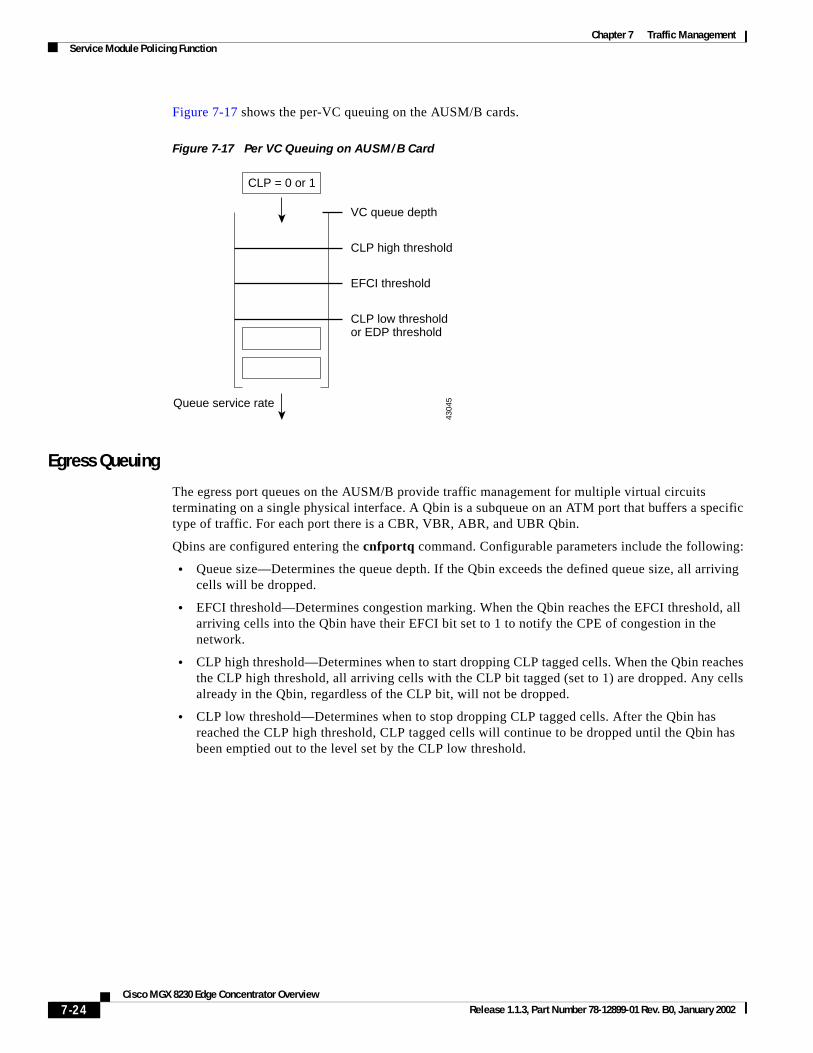
The VC queue has several thresholds associated with it to mark and respond to congestion. The EFCI threshold defines the point where the MGX concentrator will tag incoming cells with the EFCI bit. The CLP high and low thresholds determine when CLP tagged cells (CLP = 1) are discarded in the VC queue if CLP hysteresis is enabled for the connection (cnfchanq command). If frame-based traffic control is enabled, the EPD threshold determines when to start discarding an AAL5 frame. A connection can have only one method enabled; either CLP hysteresis or frame-based discard.
In summary, configurable VC queuing characteristics include the following:
• VC queue depth—The size of the VC queue, in cells up to 16000. When the VC queue reaches its configured depth, all arriving cells are discarded.
• CLP high threshold—Determines when to start dropping CLP tagged cells. When the VC queue reaches the CLP high threshold, all arriving cells with the CLP bit tagged (set to 1) are dropped. Any cells already in the queue, regardless of the CLP bit, are not dropped.
• CLP low threshold—Determines when to stop dropping CLP tagged cells. After the VC queue has reached the CLP high threshold, CLP tagged cells will continue to be dropped until the queue has emptied out to the level determined by the CLP low threshold.
• EPD threshold—Determines when to begin dropping AAL5 frames. If the VC queue is above the EPD threshold when the first cell from an AAL5 frame arrives, all cells from that frame are discarded.
• EFCI threshold—Determines congestion marking. When the VC queue reaches the EFCI threshold, all arriving cells into the VC queue have their EFCI bit set to 1 to notify the end-user equipment of congestion in the network.
7-23Cisco MGX 8230 Edge Concentrator Overview
Release 1.1.3, Part Number 78-12899-01 Rev. B0, January 2002
Chapter 7 Traffic ManagementService Module Policing Function
Figure 7-17 shows the per-VC queuing on the AUSM/B cards.
Figure 7-17 Per VC Queuing on AUSM/B Card
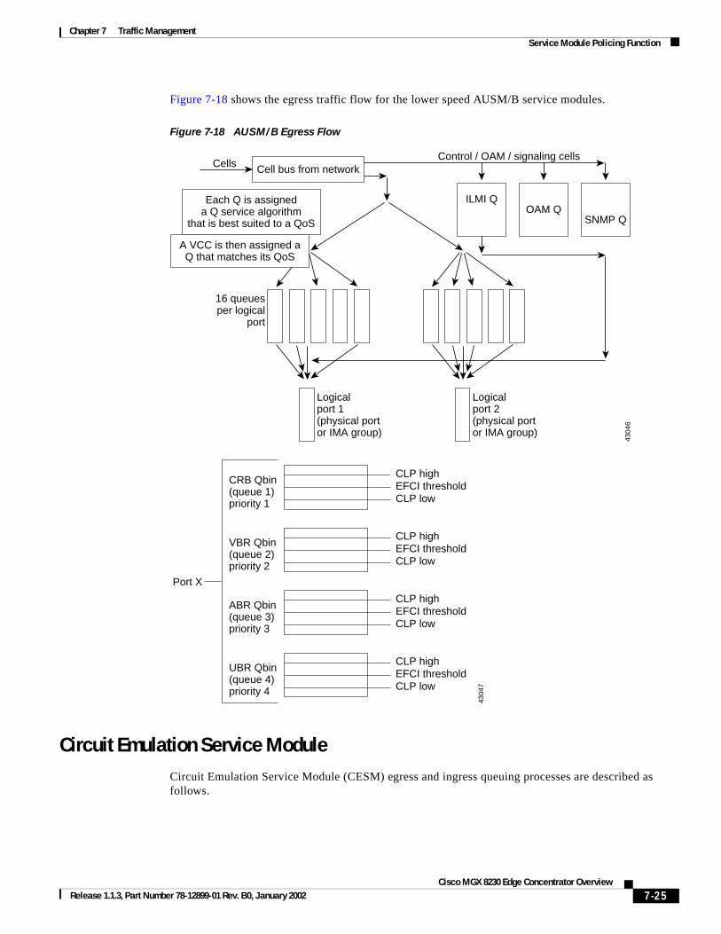
Egress Queuing
The egress port queues on the AUSM/B provide traffic management for multiple virtual circuits terminating on a single physical interface. A Qbin is a subqueue on an ATM port that buffers a specific type of traffic. For each port there is a CBR, VBR, ABR, and UBR Qbin.
Qbins are configured entering the cnfportq command. Configurable parameters include the following:
• Queue size—Determines the queue depth. If the Qbin exceeds the defined queue size, all arriving cells will be dropped.
• EFCI threshold—Determines congestion marking. When the Qbin reaches the EFCI threshold, all arriving cells into the Qbin have their EFCI bit set to 1 to notify the CPE of congestion in the network.
• CLP high threshold—Determines when to start dropping CLP tagged cells. When the Qbin reaches the CLP high threshold, all arriving cells with the CLP bit tagged (set to 1) are dropped. Any cells already in the Qbin, regardless of the CLP bit, will not be dropped.
• CLP low threshold—Determines when to stop dropping CLP tagged cells. After the Qbin has reached the CLP high threshold, CLP tagged cells will continue to be dropped until the Qbin has been emptied out to the level set by the CLP low threshold.
4304
5
CLP = 0 or 1
VC queue depth
CLP high threshold
EFCI threshold
CLP low thresholdor EDP threshold
Queue service rate
7-24Cisco MGX 8230 Edge Concentrator Overview
Release 1.1.3, Part Number 78-12899-01 Rev. B0, January 2002
Chapter 7 Traffic ManagementService Module Policing Function
Figure 7-18 shows the egress traffic flow for the lower speed AUSM/B service modules.
Figure 7-18 AUSM/B Egress Flow
Circuit Emulation Service ModuleCircuit Emulation Service Module (CESM) egress and ingress queuing processes are described as follows.
4304
6
Cell bus from network
Logicalport 2(physical portor IMA group)
Each Q is assigneda Q service algorithm
that is best suited to a QoS
A VCC is then assigned aQ that matches its QoS
Logicalport 1(physical portor IMA group)
16 queuesper logical
port
ILMI Q
SNMP QOAM Q
CellsControl / OAM / signaling cells
4304
7CRB Qbin(queue 1)priority 1
CLP high
Port X
EFCI thresholdCLP low
VBR Qbin(queue 2)priority 2
CLP highEFCI thresholdCLP low
ABR Qbin(queue 3)priority 3
CLP highEFCI thresholdCLP low
UBR Qbin(queue 4)priority 4
CLP highEFCI thresholdCLP low
7-25Cisco MGX 8230 Edge Concentrator Overview
Release 1.1.3, Part Number 78-12899-01 Rev. B0, January 2002
Chapter 7 Traffic ManagementService Module Policing Function
Egress Queuing
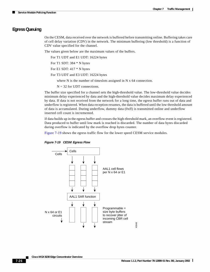
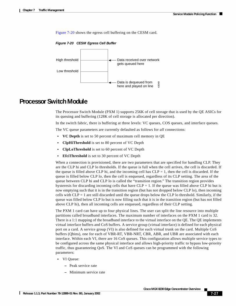
On the CESM, data received over the network is buffered before transmitting online. Buffering takes care of cell delay variation (CDV) in the network. The minimum buffering (low threshold) is a function of CDV value specified for the channel.
The values given below are the maximum values of the buffers.
For T1 UDT and E1 UDT: 16224 bytes
For T1 SDT: 384 * N bytes
For E1 SDT: 417 * N bytes
For T3 UDT and E3 UDT: 16224 bytes
where N is the number of timeslots assigned in N x 64 connection.
N = 32 for UDT connections.
The buffer size specified for a channel sets the high-threshold value. The low-threshold value decides minimum delay experienced by data and the high-threshold value decides maximum delay experienced by data. If data is not received from the network for a long time, the egress buffer runs out of data and underflow is registered. When data reception resumes, the data is buffered until the low threshold amount of data is accumulated. During underflow, dummy data (0xff) is transmitted online and underflow inserted cell count is incremented.
If data builds up in the egress buffer and crosses the high-threshold mark, an overflow event is registered. Data produced to buffer until low mark is reached is discarded. The number of data bytes discarded during overflow is indicated by the overflow drop bytes counter.
Figure 7-19 shows the egress traffic flow for the lower speed CESM service modules.
Figure 7-19 CESM Egress Flow
4304
8
Cells
AAL1 SAR function
Cells
N x 64 or E1circuits
Programmable =size byte buffersto recover jitter ofincoming CBR cellstream
AAL1 cell flowsper N x 64 or E1
7-26Cisco MGX 8230 Edge Concentrator Overview
Release 1.1.3, Part Number 78-12899-01 Rev. B0, January 2002
Chapter 7 Traffic ManagementService Module Policing Function
Figure 7-20 shows the egress cell buffering on the CESM card.
Figure 7-20 CESM Egress Cell Buffer
Processor Switch ModuleThe Processor Switch Module (PXM 1) supports 256K of cell storage that is used by the QE ASICs for its queuing and buffering (128K of cell storage is allocated per direction).
In the switch fabric, there is buffering at three levels: VC queues, COS queues, and interface queues.
The VC queue parameters are currently defaulted as follows for all connections:
• VC Depth is set to 50 percent of maximum cell memory in QE
• ClpHiThreshold is set to 80 percent of VC Depth
• ClpLoThreshold is set to 60 percent of VC Depth
• EfciThreshold is set to 30 percent of VC Depth
When a connection is provisioned, there are two parameters that are specified for handling CLP. They are the CLP hi and CLP lo thresholds. If the queue is full when the cell arrives, the cell is discarded. If the queue is filled above CLP hi, and the incoming cell has CLP = 1, then the cell is discarded. If the queue is filled below CLP lo, then the cell is enqueued, regardless of its CLP setting. The area of the queue between CLP hi and CLP lo is called the “transition region.” The transition region provides hysteresis for discarding incoming cells that have CLP = 1. If the queue was filled above CLP hi but is now emptying such that it is in the transition region (but has not dropped below CLP lo), then incoming cells with CLP = 1 are still discarded until the queue drops below the CLP lo threshold. Similarly, if the queue was filled below CLP lo but is now filling such that it is in the transition region (but has not filled above CLP hi), then all incoming cells are enqueued, regardless of their CLP setting.
The PXM 1 card can have up to four physical lines. The user can split the line resource into multiple partitions called broadband interfaces. The maximum number of interfaces on the PXM 1 card is 32. There is a 1:1 mapping of the broadband interface to the virtual interface on the QE. The QE implements virtual interface buffers and CoS buffers. A service group (virtual interface) is defined for each physical port on a card. A service group (VI) is also defined for each virtual trunk on the card. Multiple CoS buffers (Qbins), one for each of VBR-RT, VBR-NRT, CBR, ABR, and UBR are associated with each interface. Within each VI, there are 16 CoS queues. This configuration allows multiple service types to be configured across the same physical interface and allows high-priority traffic to bypass low-priority traffic, thus guaranteeing QoS. The VI and CoS queues can be programmed with the following parameters:
• VI Queue:
– Peak service rate
– Minimum service rate
4304
9
Data received over networkgets queued here
High threshold
Low threshold
Data is dequeued fromhere and played on line
7-27Cisco MGX 8230 Edge Concentrator Overview
Release 1.1.3, Part Number 78-12899-01 Rev. B0, January 2002
Chapter 7 Traffic ManagementService Module Policing Function
• CoS Queue:
– Minimum service rate
– Maximum queue depth
– Frame discard enable
– Thresholds for discarding cells tagged with CLP bit set
– Threshold for setting the EFCI bit.
– Priority level 1–16
– Various statistics for debugging
Figure 7-21 CoS Queuing Process
VI and CoS Queues Architecture
There are three VI and CoS queuing flows:
1. SM1 ↔ QE0 ↔ SM2
2. SM1 →QE1 →PXM 1 uplink
3. PXM 1 uplink →QE0 →SM1
All the above connection topologies follow the same queuing flow on PXM 1. It is a two-stage process.
Stage 1: VI selection
Based on the minimum rate of each VI (there are 32 VIs on each QE; on QE0, each slot is mapped to a VI, and on PXM 1 uplink, each VI is mapped to a virtual interface—a logical partition of a physical link), QE selects one VI it needs to service to satisfy the rate requirement.
Stage 2: Qbin selection
Based on the Qbin MIN rate of each Qbin of the selected VI in stage 1, a Qbin is selected.
Once a Qbin is selected, the cell at the head of that Qbin queue is moved to the output queue for that physical link or slot to be transmitted.
Cells do not physically pass the VCQ. However, when a cell is being serviced, accounting is done for VCQ threshold function.
Incoming traffic
To PXM port 1CoS 1CoS 16
VI
To slot 1CoS 1CoS 16
VI
4305
0
7-28Cisco MGX 8230 Edge Concentrator Overview
Release 1.1.3, Part Number 78-12899-01 Rev. B0, January 2002
Chapter 7 Traffic ManagementCongestion Control Mechanisms
On the PXM 1, each QE is used for both directions (ingress and egress). Note that ingress and egress are defined from the perspective of QE on PXM 1 whereas on BXMs they are defined from the perspective of the backplane. With this definition, each switch path (except those terminating on PXM 1) has an ingress segment and an egress segment.
• Ingress—from trunk port to QE, or cell bus to QE
• Egress—from QE to trunk port, or from QE to cell bus
Separate queues can be used to support IP QoS.
IP QoS mechanisms use the three precedence bits in the type of service (ToS) field of the IP header to indicate IP precedence. Precedence values are used within the network to implement different service classes. There can be as many service classes as there are unique values of this three-bit field. Two of these values are reserved for traffic control, leaving six unique values for assignment to service classes.
Effective coupling of IP and ATM QoS is particularly challenging because of the differing paradigms (connectionless vs. connection-oriented). However, providing a seamless QoS capability between IP and ATM is essential when ATM is used as the backbone transport infrastructure for an IP VPN. This scenario allows QoS for intranet-based IP applications to take advantage of ATM QoS capabilities. MPLS is the key to this seamless integration.
In a VPN-aware network, the label header includes a CoS field with three bits to indicate a packet service class in a label-switched network. This value may be copied from the IP header when the label is applied, or it may be explicitly set by a precedence policy on the service provider edge router. As in an IP network, the CoS value is used to denote service class for each packet. When MPLS is implemented in an IP network, IP QoS capabilities are used the same way as in a traditional IP-routed network. In this case, however, service class is indicated by the CoS field in the label header instead of the IP header.
When the core of the service provider network uses ATM label switches, additional QoS capabilities are possible; they include:
• Use of available bit rate (ABR) on labeled VCs
• Use of parallel VCs for different precedence levels
Cisco edge concentrators such as the MGX 8230 provide IP service classes in addition to the standard ATM classes. These IP classes use a class-based queuing (CBQ) mechanism to implement separate queuing for IP flows while still utilizing the OptiClass buffer management feature to manage system buffers. This scenario allows the edge concentrator to provide ATM and Frame Relay services in parallel with IP while optimally allocating buffer space for all services.
Alternatively, MPLS allows a separate label VC to be used for each precedence value to a given destination. A percentage of link bandwidth can be allocated to each class of traffic using WFQ among classes to ensure that each class receives its allocated share of the link bandwidth. With the Cisco OptiClass buffer management feature, any unused bandwidth is automatically available to other classes. It is necessary to provision the link share appropriately to provide higher QoS to the higher classes. For example, if ten percent of the offered load on a link is expected to belong to a “premium” class, then allocating 15 percent of the link to the class with WFQ will ensure low-loss, low-delay service to that class.
Congestion Control MechanismsThe AUSM/B modules perform ForeSight_ABR functions as the closed-loop end-to-end traffic management. These mechanisms allow maximizing the link utilization and avoiding the network congestion. The PXM1 supports EFCI tagging. Network uses the EFCI bit in the ATM cell header to
7-29Cisco MGX 8230 Edge Concentrator Overview
Release 1.1.3, Part Number 78-12899-01 Rev. B0, January 2002
Chapter 7 Traffic ManagementCongestion Control Mechanisms
indicate congestion. When congested, the concentrator sets an EFCI flag. The receiver must respond with “marked” RM cells and the sender will slow down upon receiving Congestion Indication (CI) in the Backward Resource Management cell (BRM).
The AUSM/B card conforms to ForeSight as a congestion-control mechanism. Based on the congestion status of the concentrator, the MGX 8230 can:
• Do nothing
• Set the CI bit in the RM cells
• Set the EFCI bit in the users cells
• Clear the EFCI bit on abatement
EFCI BitThe different service modules on the MGX 8230 react to a set EFCI bit. Depending on the configuration, each service module can take different actions upon receiving a cell with the EFCI bit set.
The EFCI bit is used in the AUSM/B as mentioned follows:
• For both the ingress and egress side, whenever the AUSM/B gets a cell, it is put it onto the corresponding queue. In case the qdepth exceeds EFCI threshold, the EFCI indication is set on the cell, else the EFCI bit is cleared. The incoming EFCI indication is overwritten with the new EFCI status.
• In case of ABR channel with ForeSight enabled, the rate-down message is sent on the network whenever there is
– EFCI set cells received from the network
– EFCI set cells transmitted onto the port side
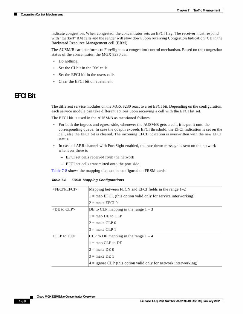
Table 7-8 shows the mapping that can be configured on FRSM cards.
Table 7-8 FRSM Mapping Configurations
<FECN/EFCI> Mapping between FECN and EFCI fields in the range 1–2
1 = map EFCI, (this option valid only for service interworking)
2 = make EFCI 0
<DE to CLP> DE to CLP mapping in the range 1 – 3
1 = map DE to CLP
2 = make CLP 0
3 = make CLP 1
<CLP to DE> CLP to DE mapping in the range 1 – 4
1 = map CLP to DE
2 = make DE 0
3 = make DE 1
4 = ignore CLP (this option valid only for network interworking)
7-30Cisco MGX 8230 Edge Concentrator Overview
Release 1.1.3, Part Number 78-12899-01 Rev. B0, January 2002
Chapter 7 Traffic ManagementCongestion Control Mechanisms
EPD/PPD ImplementationThe type of frame-discard mechanism is configurable per connection.
The QE uses an EPD feature as acceptance criteria for new AAL5 frames. This feature is also referred to as packet discard (PD) and frame-based traffic control (FBTC). Two EPD thresholds apply selective cell-discard principles to new frame acceptance criteria. EPD0 applies to all cells, while EPD1 applies only to cells with CLP=1. These are explained further as follows.
In addition to EPD, the QE implements a random early detection (RED) feature, in which full frames are randomly discarded with increasing probability as the CoS buffer’s time-averaged queue length approaches its EPD threshold. It has been shown that RED improves the performance of TCP connections.
Early Packet Discard
EPD uses the EPD0 and EPD1 thresholds for the VCs and classes of service as the acceptance criteria for new AAL5 frames. The start of frame (SOF) cell is determined to be the next cell to arrive following an AAL5 end-of-frame (EOF) cell.
EPD attempts to discard entire frames. However, it is possible that a cell is discarded after one or more cells of the frame have been accepted. In this case, the remainder of the frame is discarded, except that the EOF is evaluated independently (to avoid corrupting the next new frame). This is referred to as tail packet discard. In this case, if the EOF is discarded at the end of a tail discard, the next frame is also discarded, to avoid sending a corrupted frame.
The QE allows packet-discard features to be enabled on a per-connection basis. To implement these features, the QE maintains a packet-discard state for each connection that has packet discard enabled. The purpose of maintaining the states is to differentiate between a full-packet discard and tail-packet (partial) discard. There are four packet discard states:
• Start of frame—Next cell to arrive is a start of frame (SOF).
• Cells accepted—SOF was accepted.
• Partial (tail) discard—All cells are discarded until the EOF arrives. EPF is preferentially treated to avoid discard.
• Full discard—All cells are discarded until the EOF arrives (EOF is discarded).
Transitions between the states occur only upon arrival of user data cells for the corresponding connection. When an EOF cell arrives, the state machine goes to the SOF state. If an SOF cell arrives, and its corresponding cell count exceeds its VC EPD threshold (or the CoS EPD threshold is exceeded), then the cell is discarded. Note that there are separate EPD0 and EPD1 thresholds for the CLP(0+1) and CLP(1) SOF cells. That is, if any SOF cell arrives, and the cell count exceeds the EPD0 threshold, the SOF (and the following frame) is discarded. However, if the SOF cell has CLP=1, and the cell count exceeds the EPD1 threshold (which is usually programmed lower than the EPD0 threshold), then the SOF cell is also discarded in this case.
The Route Processor Module (RPM) through the Port Adapter PA-A3 can perform EDP. The shaper will drop whole packets.
7-31Cisco MGX 8230 Edge Concentrator Overview
Release 1.1.3, Part Number 78-12899-01 Rev. B0, January 2002
Chapter 7 Traffic ManagementCongestion Control Mechanisms
7-32Cisco MGX 8230 Edge Concentrator Overview
Release 1.1.3, Part Number 78-12899-01 Rev. B0, January 2002