Embed Size (px)
Citation preview

TRADITIONAL TELEPHONY

Public Switched Telephony Network
Telephone
PBX
PBX
COSwitch
COSwitch
Telephone
Telephone
InterofficeTrunk CO
Trunk
Tie Trunk
LocalLoop
PSTN
Enterprise
Enterprise

Traditional Business Phone System
COSwitch
PBX Key System
COSwitch
Analog or Digital Handsets
Digital Handsets
Local Loop
Local Loop
Tie Line
CustomerTelephone

What Is a PBX?
PBX
Terminal InterfacePower Supply & Fans
Terminal InterfaceControl Complex
Terminal InterfaceSwitching Network
Terminal InterfaceTerminal Interface
Line Card Trunk Card
LineTrunk
LocalExchange

What Is a Key System?
Key System
TerminationBlocks
ConnectorBlock
Trunks
Main Distribution Frame
Power Supply
Intercom Cards
Station Cards
Station Cards
CO Line Cards
LocalExchange
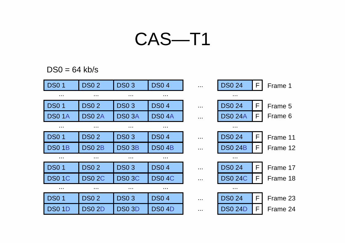
Comparing Key Systems to PBXs
Press a button to access outside line
Dial 9 or other access number to
access outside line
Method for Accessing
Outside Trunks
Small company or branch office (typically
50 or fewer users)
Large company site (typically more than
50 users)
Typical Installation
Not a switchSimilar to the CO
switchSwitch
Functionality
Analog or digitalPrimarily digitalTechnology
Key SystemPBX

Signaling Types
– There are three types of signaling used in a telephony network:
• Supervisory signaling communicates the state of a telephony device.
• Address signaling sends information about the digits dialed.
• Informational signaling communicates the current state of the call.
– Signaling can be sent either in-band or out-of-band.• In-band signaling sends the signaling in the same
communications channel as the voice.• Out-of-band signaling sends the signaling in a
separate communications channel from the voice.

Supervisory Signaling
On Hook
Off Hook
Ringing
Handset on Cradle and Switch Hook Open
TelephoneSwitch
TelephoneSwitch
TelephoneSwitch
Local Loop
Local Loop
Local LoopLocal Loop
Local Loop
Local Loop
DC CurrentDial Tone
RingbackTone DCCurrent
Off HookClosedCircuit
Off HookClosedCircuit
RingingVoltage
–48 DC Voltage (Battery)DC Open CircuitNo Current Flow

Address Signaling
– Tone telephone• DTMF dialing
– Rotary telephone• Pulse dialing

Informational Signaling Example
Frequency modulation 1 kHz
Frequency modulation 1 kHz
Confirmation tone
ContinuousContinuous200 to 400No such number
0.10.1(1400 + 2060 + 2450 + 2600)
Receiver off hook
0.20.3480 + 620Reorder (local)
0.30.2480 + 620Congestion (toll)
31440 + 480Ringback, PBX
42440 + 480Ringback, line
0.50.5480 + 620Busy
ContinuousContinuous350 + 440Dial
Off Time (Sec)On Time (Sec)Frequency (Hz)Tone
This information will vary based on the country.

Signaling System 7
• SS7 functions:– Informational signaling– Call setup– Call routing– Call billing– Toll-free number resolution– Used out-of-band signaling
CO Switch CO SwitchSS7

PSTN Call Setup
1. Customer phone goes off hook creating a closed circuit.
2. The customer’s CO switch detects that current is flowing and generates dial tone to the customer phone.
3. Either DTMF or pulse digits are dialed by the customer.
4. The CO switch collects the digits and performs an SS7 lookup to determine the destination CO switch.
5. Supervisory signaling indicates to the far-end analog or digital trunk that an inbound call has arrived.
6. The PBX determines which internal extension the call should go to and causes the target handset with that extension to ring.
7. Ringback is generated to the customer phone by their local CO switch.
8. The target handset goes off hook and a circuit is built end-to-end.
PSTNCustomerTelephone
Analog Circuit
Digital or Analog Trunk
PBX
TargetHandset
COSwitch
COSwitch

Numbering Plans
– A numbering plan is a numbering scheme with the following characteristics:
• Defines a set of rules to allocate numbers used in telecommunications
• Is based on international telecommunications standards
• Is established by numbering plan authorities, which regulate thedistribution of numbers and codes in their territory
– Many regional and national numbering plans exist:
• NANP
• U.K. National Numbering Scheme• ETNS
• Hong Kong
• Many countries have their own numbering plans

North American Numbering Plan
– NANP is the numbering plan for the United States and its territories, Canada, Bermuda, and many Caribbean nations.
– It is administered by the NANPA.– NANP numbers are 10-digit numbers.
X = <0-9>
Area CodeLocal Number:
NXX – CO CodeXXXX – Line Number
N = <2-9>
NXX-NXX-XXXX

E.164 Addressing
• E.164 is an international numbering plan for public telephony systems:– A valid number contains the following
components:• Country code • National destination code• Subscriber number
– Each number can be up to 15 digits long.
– The E.164 plan was developed by the ITU.

ANALOG TELEPHONY

Components of an Analog Telephone
– Receiver
– Transmitter– Two-wire/four-wire hybrid
– Dialer (DTMF or pulse)– Switch hook
– Ringer

FXS Interface
– Connects directly to analog phones or faxes– Provisions local service– Emulates the CO to the attached devices– Provides power, call progress tones, and dial tone
FXS
FXS
FXS

FXO Interface
– Connects directly to office equipment– Used to make and receive calls from the PSTN– Can be used to connect through the PSTN to another site– Answers inbound calls
FXO FXOPSTN

Loop-Start Signaling
COPhone
-48 VDC
Open Circuit
On Hook
COPhone
-48 VDC
Closed Circuit
Off Hook
COPhone
AC Applied
Closed Circuit
On-Hook Ringing
Ringer
X
Loop-start signaling is typically used in residential environments.

Ground-Start Signaling
CO or FXSFXO or PBX
Open Circuit
On hook
CO or FXSSeized
Open Circuit
FXO or PBX
Current Applied
Ring
Tip
Ring
Tip
Ground-start signaling is typically used in business environments

E&M Interface
– Connects two sites with a leased connection– Allows for the use of non-PSTN numbers– Used to create tie-lines– Commonly used to connect to external MOH
sources
E&M E&M
E&M MOHE&M
PBXTie-Line

DIGITAL TELEPHONY

Digitizing Analog Signals
1. Sample the analog signal regularly.
2. Quantize the sample.3. Encode the value into a binary expression.
4. Compress the samples to reduce bandwidth (optional).

Step 1—Sample the Signal
Each sample is 1/8000 of a second apart.
Time
Analog Waveform

Step 2—Quantize the Signal
Segment 0
Segment 0
Segment 1
Segment 2
Segment 2
Segment 1
Time
Voltage
Each sample is 1/8000 of a second apart
+
-mu-law
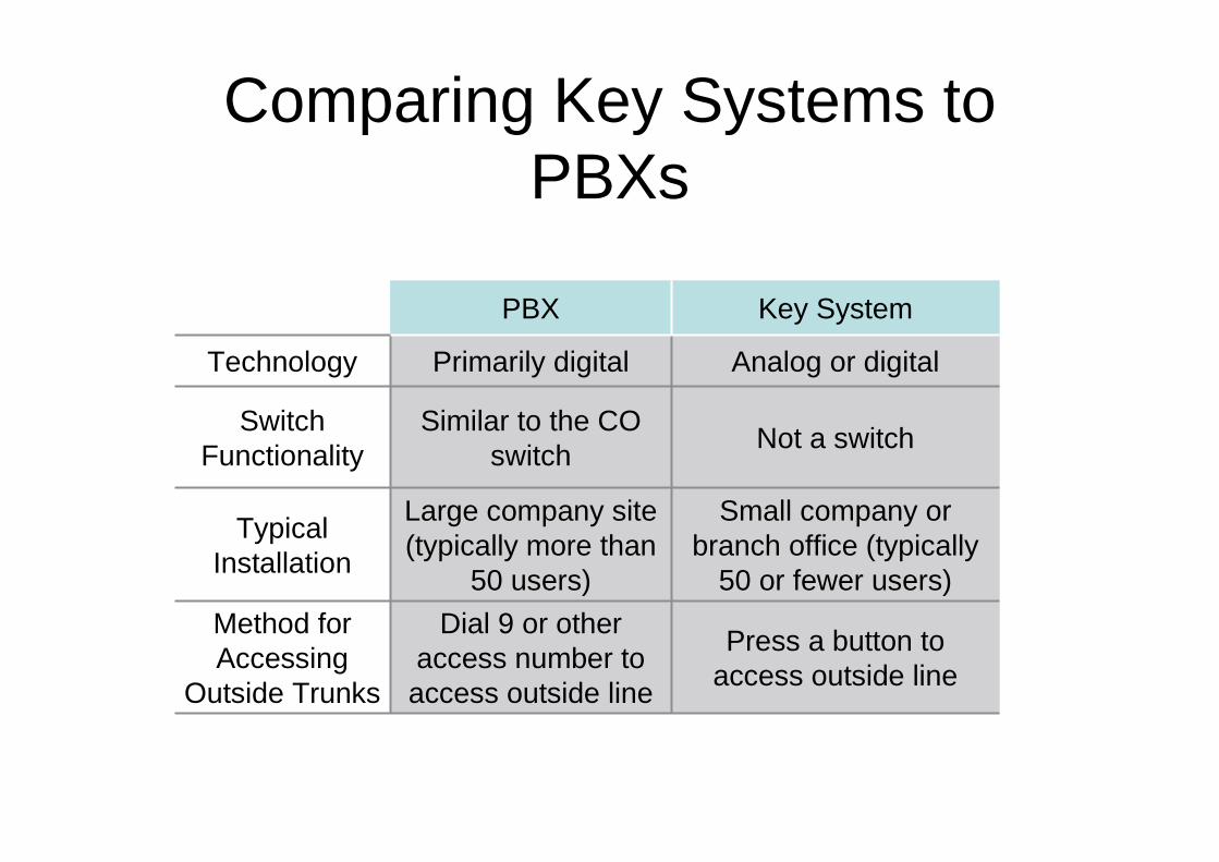
Step 3—Encode the Signal in Binary
1 0 0 1 1 1 0 0
Sign:� 1 = Positive� 0 = Negative
Segment Interval

Step 4—Compress the Samples (Optional)
– ADPCM
• Sends only the differential between the current and last sample• Uses G.726 variants
• Allows encoding PCM data rates of 16 kb/s, 24 kb/s, or 32 kb/s per call
• Has lower quality than G.729• Is not commonly used today
– CS-ACELP
• Is based on the human vocal system• Matches sounds to a codebook of possible sounds
• Uses G.729 variants
• Is the most common compression method used today• Has a data rate of 8 kb/s per call
• Provides high quality

Time-Division Multiplexing
1 1 1 1 1
2 2 2 2 2
3 3 3 3 3
4 4 4 4 4
... ... ... ... ...
24 24 24 24 24
T1 Conversations
1234 ...24 1234...
For E1, the conversations would be 1 through 30.

T1 Circuits
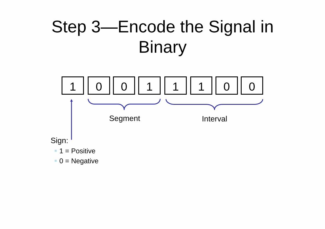
– Up to 24 channels for voice– Each channel is a DS0
– Each DS0 is 64 kb/s
– 8000 samples per second– One byte per sample
– One sample per channel, per frame
– SF groups together 12 frames – ESF groups together 24 frames
– Typically used in the United States, Canada and Japan (called J1)
T1PSTN

E1 Circuits
– Up to 30 channels for voice
– One channel for signaling
– One channel for framing– Each channel is a DS0
– Each DS0 is 64 kb/s
– 8000 samples per second in voice DS0s– One byte per sample
– One sample per channel, per frame
– 16 frames are grouped together to make a multiframe
E1PSTN

Channel Associated Signaling
2.048 Mb/s1.544 Mb/sSpeed
The rest of the worldUnited States, Canada, Japan
Where Predominately
Used
Out-of-band signaling in time slot 17
RBS in-bandSignaling Method
3024Number of
Voice Channels
CAS E1CAS T1
CAS—T1
DS0 1 DS0 2 DS0 3 DS0 4 ... DS0 24... ... ... ... ...
DS0 1 DS0 2 DS0 3 DS0 4 ...
...
DS0 24
DS0 1A DS0 2A DS0 3A DS0 4A DS0 24A... ... ... ... ...
DS0 1 DS0 2 DS0 3 DS0 4 ... DS0 24
DS0 1B DS0 2B DS0 3B DS0 4B ... DS0 24B... ... ... ... ...
DS0 1 DS0 2 DS0 3 DS0 4 ... DS0 24
DS0 1C DS0 2C DS0 3C DS0 4C ... DS0 24C... ... ... ... ...
F
F
F
F
F
F
F
DS0 1 DS0 2 DS0 3 DS0 4 ... DS0 24
DS0 1D DS0 2D DS0 3D DS0 4D ... DS0 24D
F
F
Frame 1
Frame 5
Frame 6
Frame 12
Frame 17
Frame 11
Frame 24
Frame 23
Frame 18
DS0 = 64 kb/s

CAS—E1
DS0 1 DS0 2 DS0 3 ... DS0 31
DS0 = 64kb/s
DS0 16 DS0 17 ... DS0 32DS0 18
Time slots 2–16 and 18–32 contain the voice conversations.
Time slot 1 contains framing information.
Time slot 17 contains the out-of-band signaling
information.
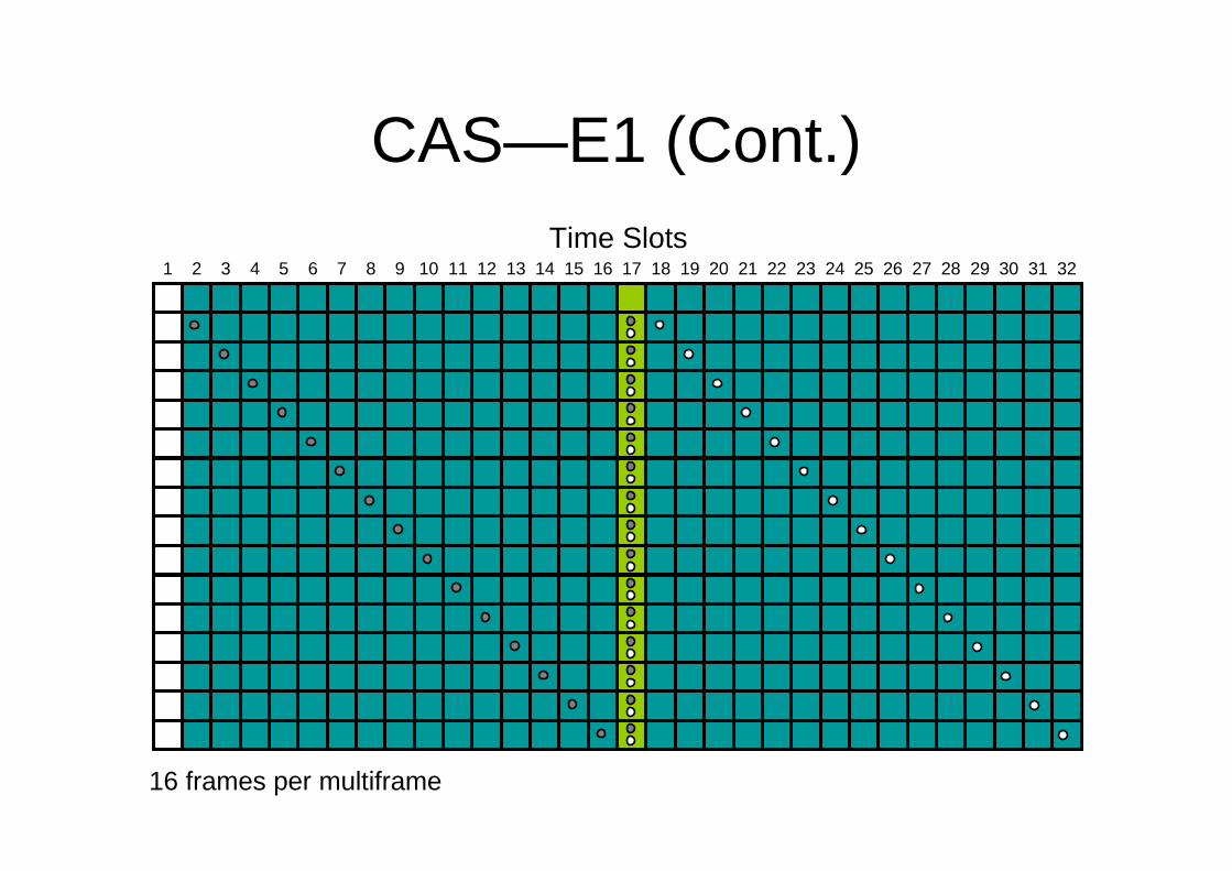
CAS—E1 (Cont.)
16 frames per multiframe
1 2 3 4 5 6 7 8 9 10 11 12 13 14 15 16 17 18 19 20 21 22 23 24 25 26 27 28 29 30 31 32
Time Slots
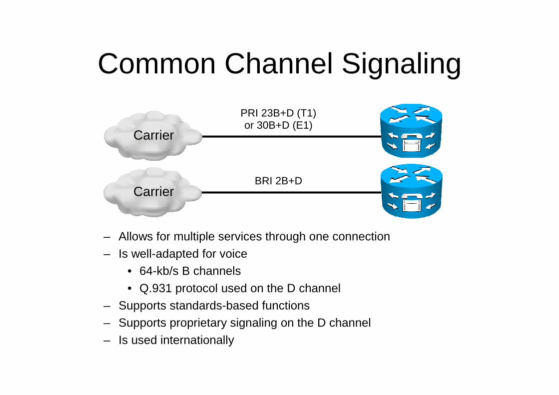
Common Channel Signaling
– Allows for multiple services through one connection
– Is well-adapted for voice• 64-kb/s B channels
• Q.931 protocol used on the D channel
– Supports standards-based functions– Supports proprietary signaling on the D channel
– Is used internationally
PRI 23B+D (T1)or 30B+D (E1)
BRI 2B+D
Carrier
Carrier

CCS—PRI T1
Time slots 1–23 are the B channels and contain voice, video, or data.
TS 1 TS 2 TS 3 TS 4 TS 5 TS 6 ... TS 23 TS 24 F
The B and D channels are all 64 kb/s Time slot 24 contains the
out-of-band signaling and is called the D channel.
A framing bit on the end of the frame.

CCS—PRI E1
Time slots 2–16 and 18–32 are the B channels and contain voice, video or data.
The B and D channels are all 64 kb/s
Time slot 17 contains the out-of-band signaling
information.
Time slot 1 contains framing information.
DS0 1 DS0 2 DS0 3 ... DS0 31DS0 16 DS0 17 ... DS0 32DS0 18

CCS—BRI
Framing bit
The 32 bits total for the two B channels contain the voice, video, or data.
The four total D bits contain the signaling information.
The two B channels are 64 kb/s;the D channel is 16 kb/s
F B 1 B 2 B 1 B 2D D D D

UNDERSTANDING PACKETIZATION

Digital Signal Processors
PSTN
PSTN
PSTN
IP
IP
IP
Analog or Digital
Analog or Digital
Analog or Digital
Speech IP Packets
IP Packets
IP Packets
IP Packets
DSPs
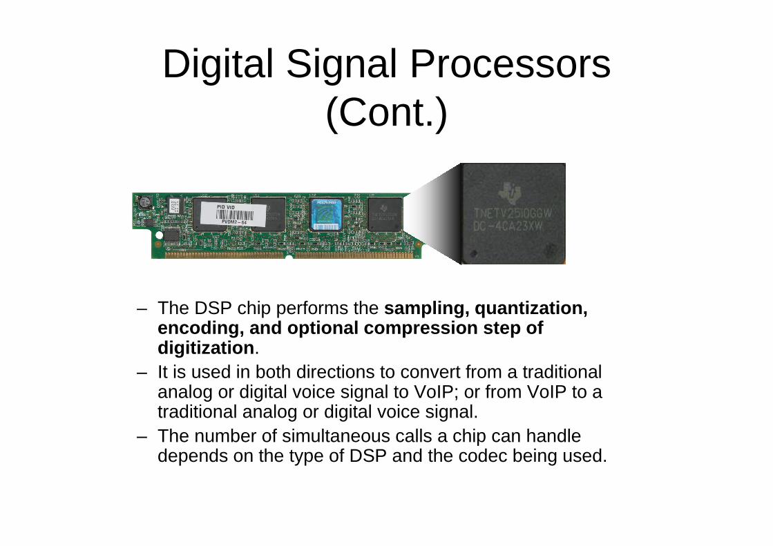
Digital Signal Processors (Cont.)
– The DSP chip performs the sampling, quantization, encoding, and optional compression step of digitization.
– It is used in both directions to convert from a traditional analog or digital voice signal to VoIP; or from VoIP to a traditional analog or digital voice signal.
– The number of simultaneous calls a chip can handle depends on the type of DSP and the codec being used.
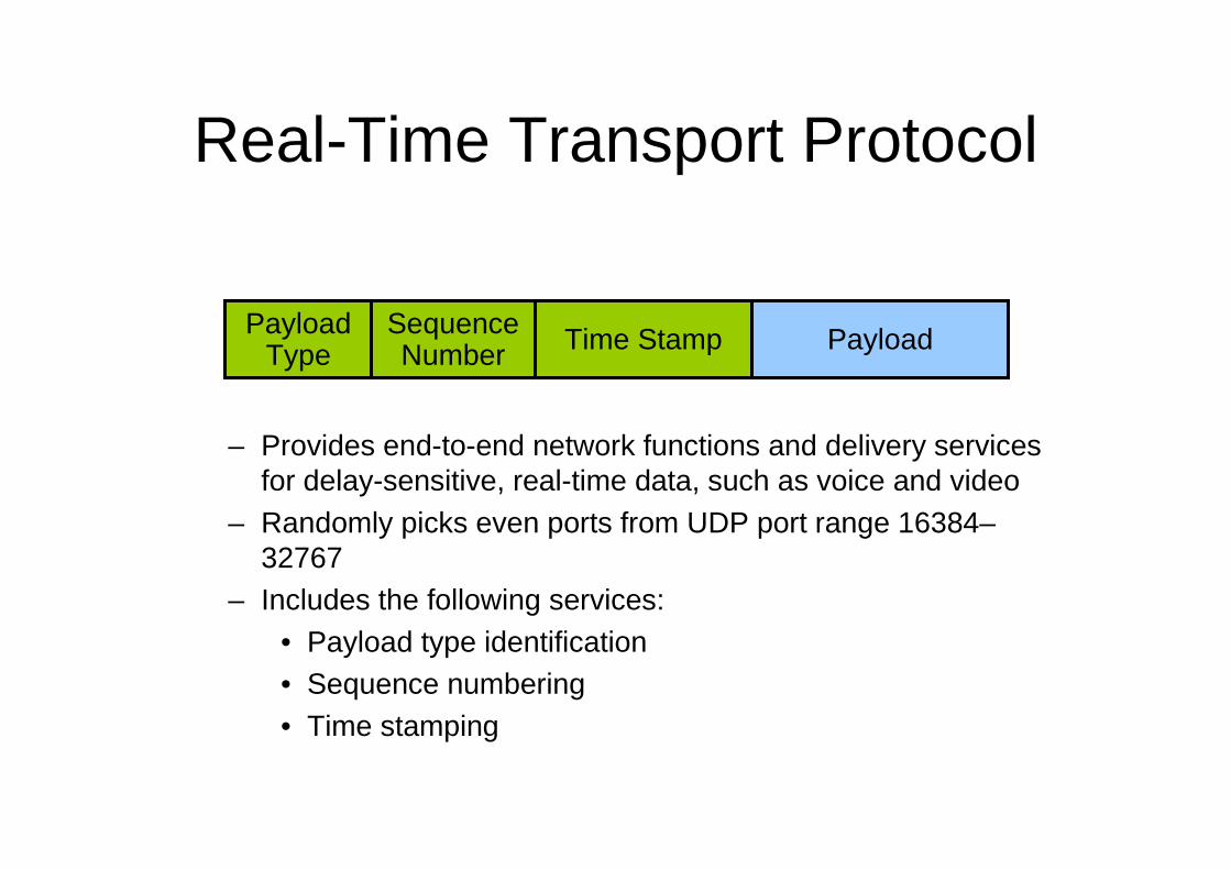
Real-Time Transport Protocol
– Provides end-to-end network functions and delivery services for delay-sensitive, real-time data, such as voice and video
– Randomly picks even ports from UDP port range 16384–32767
– Includes the following services:• Payload type identification• Sequence numbering• Time stamping
Payload Type
Sequence Number Time Stamp Payload

RTP Control Protocol
– Can be used to monitor the quality of the data distribution and provide control information
– Provides feedback on current network conditions– Allows hosts that are involved in an RTP session to exchange
information about monitoring and controlling the session:• Packet count• Packet delay• Octet count• Packet loss• Jitter (variation in delay)
– Provides a separate flow from RTP for UDP transport use– Is paired with its RTP stream and uses the same port as the
RTP stream plus 1 (odd-numbered port)
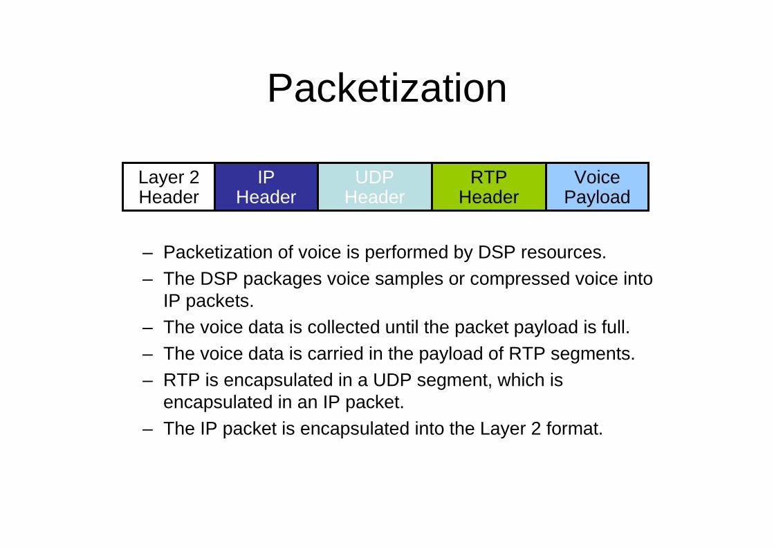
Packetization
– Packetization of voice is performed by DSP resources.– The DSP packages voice samples or compressed voice into
IP packets.– The voice data is collected until the packet payload is full.– The voice data is carried in the payload of RTP segments.– RTP is encapsulated in a UDP segment, which is
encapsulated in an IP packet.– The IP packet is encapsulated into the Layer 2 format.
Layer 2 Header
IP Header
UDP Header
Voice Payload
RTP Header

Packetization—G.711 Example
...
10010111 10010110 10010101 10010100 10010011 ... 10110001RTP Header
Sample 1
Sample 2
Sample 3
Sample 4
Sample 5
Sample 160
G.711 20 ms of samples (160 bytes)
10010111
10010110
10010101
10010100
10010011
10110001

Packetization—G.729 Example
...
20 Bytes of Voice PayloadRTP Header
Sample 1
Sample 2
Sample 3
Sample 4
Sample 160
G.729 20 ms of voice contained in packet
DSP Compression
10010111
10010110
10010101
10010100
10110001

Codecs
• Standardized ways to encode voice for transport across a data network:– PCM
• G.711 rate: 64 kb/s = (2 x 4 kHz) x 8 bits/sample– ADPCM
• G.726 rate: 32 kb/s = (2 x 4 kHz) x 4 bits/sample• G.726 rate: 24 kb/s = (2 x 4 kHz) x 3 bits/sample• G.726 rate: 16 kb/s = (2 x 4 kHz) x 2 bits/sample
– LD-CELP• G.728 rate: 16 kb/s
– CS-ACELP• G.729: rate 8kb/s• Annex A variant—less processor-intensive and allows more
voice channels encoded per DSP• Annex B variant—VAD and CNG
– iLBC• Rate: 13.3 kb/s
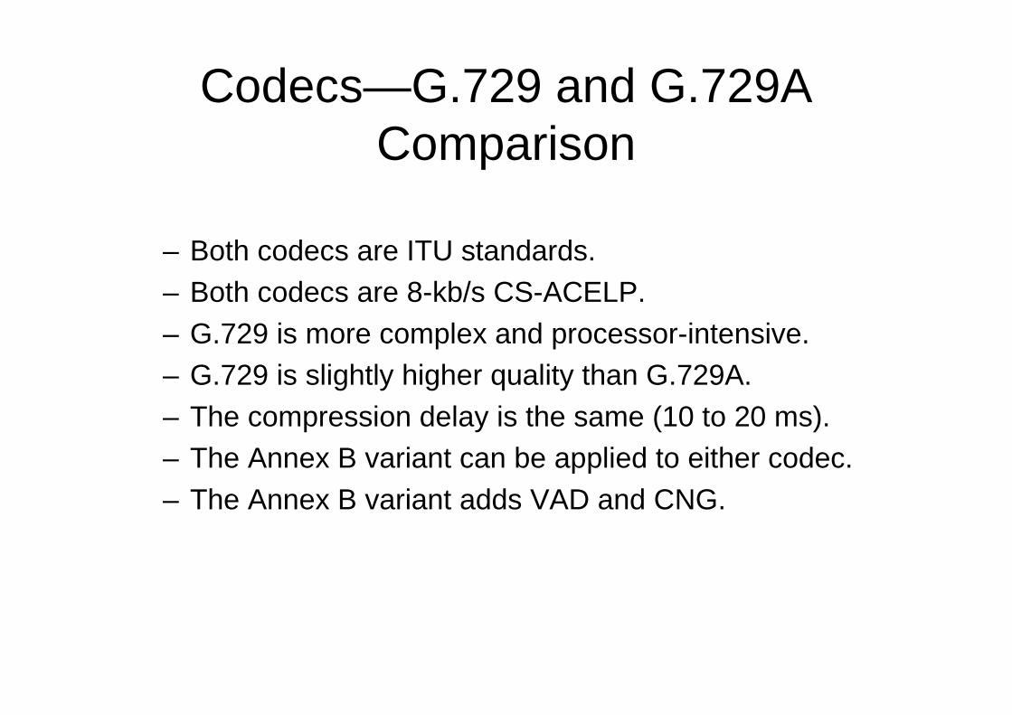
Codecs—G.729 and G.729A Comparison
– Both codecs are ITU standards.– Both codecs are 8-kb/s CS-ACELP.– G.729 is more complex and processor-intensive.– G.729 is slightly higher quality than G.729A.– The compression delay is the same (10 to 20 ms).– The Annex B variant can be applied to either codec.– The Annex B variant adds VAD and CNG.

Internet Low Bitrate Codec
– Was designed for packetized communications– Is royalty free
– Has better quality than G.729
– Has similar complexity as G.279
– Supports two fixed bit-rate frame lengths: • A bit rate of 13.3 kb/s with an encoding frame length of 30 ms
• A bit rate of 15.2 kb/s with an encoding frame length of 20 ms
– Is supported only on newer Cisco Unified IP Phones:• IP Phone 7975G – IP Phone 7942G
• IP Phone 7965G – IP Phone 7921G
• IP Phone 7962G – IP Phone 7911G
• IP Phone 7945G – IP Phone 7906G– Is supported on the VoIP dial peers of Cisco voice gateways using the
following protocols:
• H.323• SIP
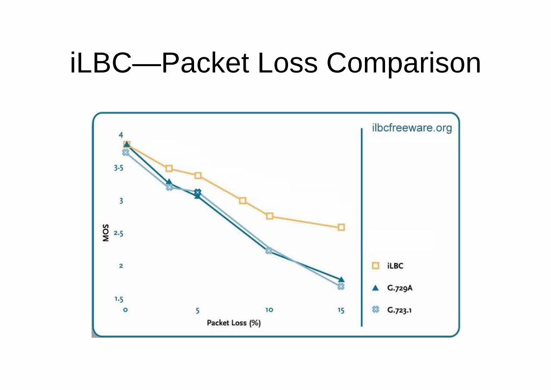
iLBC—Packet Loss Comparison

Codecs—Bandwidth Implications
*
* G.711, G.729, and iLBC are the most common codecs.
13.3kb/s
iLBC
16kb/s
G.728
8kb/s
G.729
6.3kb/s
G.723r63
16kb/s
G.726r16
5.3kb/s
24kb/s
32kb/s
64kb/s
Bandwidth not including overhead
G.723r53
G.726r24
G.726r32G.711Codec
* **

Codec—Overhead
– RTP/UDP/IP header overhead• 40 bytes of overhead• 2 or 4 bytes of overhead if using cRTP
– Data link overhead (Layer 2 header and trailer)
• Ethernet—18 bytes of overhead• MLP—6 bytes of overhead• FRF.12—6 bytes of overhead

Codec—Total Bandwidth Required
•30,400•11,200•26,400•20•8000•G.729•19,200•9600•17,200•40•8000•G.729
•46,400•19,200•34,400•20•15,200•iLBC•34,100•16,000•26,100•30•13,300•iLBC•86,400•67,200•82,400•160•64,000•G.711•78,933•66,133•76,267•240•64,000•G.711
•Ethernet•Frame Relay
with cRTP•Frame Relay
•SampleSize
•CodecSpeed
•Codec

The Effect of VAD
•17,160•26,400•20•8000•G.729•11,180•17,200•40•8000•G.729
•53,560•82,400•160•64,000•G.711•49,573•76,267•240•64,000•G.711
•Frame Relaywith VAD
•Frame Relay
•SampleSize
•CodecSpeed
•Codec
•16,965•26,100•30•13,300•iLBC•22,360•34,400•20•15,200•iLBC

Additional DSP Functions
– Hardware-based conferencing
– MTP– Transcoding between two different codecs– Echo cancellation

INTRODUCING SIGNALING PROTOCOL

VoIP Signaling Protocols
– Signaling generates and monitors the call control information between two endpoints to:
• Establish the connection• Monitor the connection• Release the connection
– The signaling protocol must pass supervisory, informational, and address signaling.
– Signaling protocols can be peer-to-peer or client/server-based.
• Peer-to-peer allows the endpoints to contain intelligence to place calls without assistance.
• Client/server puts the endpoint under the control of a centralized intelligence point.

VoIP Signaling Protocols Comparison
Peer-to-peerYes, Cisco Unified IP
Phones and third-party phones
YesBasicIETFSIP
Client/serverYes, Cisco Unified IP
Phones onlyYes, limitedProprietaryNoneSCCP
Client/serverYes, limitedYesGoodIETFMGCP
Peer-to-peerNoYesVery GoodITUH.323
ArchitectureUsed on Cisco
Unified IP PhonesUsed on
GatewaysVendor
NeutralityStandards
Body

Skinny Client Control Protocol
– Signaling protocol used between Cisco Unified Communications call control platforms and Cisco Unified IP Phones
– Cisco proprietary
– Lightweight protocol– Client/server protocol
– Used for voice only and video-enabled calls

SCCP—Examples
IP NetworkCisco Unified
Communications 500 Series
IP NetworkCisco Unified
Communications Manager Express
IP NetworkCisco Unified
Communications Manager

H.323
• H.323 is a suite of protocols for voice, video, and data with the following characteristics:– A mature protocol– Based on ISDN Q.931– Vendor neutral– Peer-to-peer architecture– Supported on Cisco voice gateways and all Cisco Unified
Communications call control platforms– Widely deployed– ITU standard– Encoded into binary messages

H.323—Examples
IP NetworkCisco Unified
Communications Manager
Cisco Voice Gateway
IP Network Cisco Unified Communications
500 Series
Cisco Voice Gateway
IP NetworkCisco Unified
Communications Manager Express
Cisco Voice Gateway
IP NetworkCisco Voice
GatewayCisco Voice
Gateway

Media Gateway Control Protocol
– Is an IETF standard– Has a client/server architecture
• Call agent is the Cisco Unified Communications Manager or Cisco Unified Communications Manager Business Edition.
• The voice gateway is under the control of the call agent.– Uses plaintext protocol– Is used on Cisco voice gateways under the control of Cisco
Unified Communications Manager or Cisco Unified Communications Manager Business Edition

MGCP—Examples
IP NetworkCisco Unified
Communications Manager
Cisco Voice Gateway
IP NetworkCisco Unified
CommunicationsManager Business
Edition
Cisco Voice Gateway
Session Initiation Protocol
– Is an emerging protocol that is still evolving– Provides basic functionality between different vendors– Can be used between Cisco Unified Communications call
control products and SIP endpoints and SIP trunks– Is supported on Cisco voice gateways and Cisco Unified IP
Phones that have SIP firmware– Is a peer-to-peer architecture
• UA initiates the call• Phones, gateways, and Cisco call control devices can be
UAs– Is an IETF standard– Uses ASCII text-based messages

SIP—Examples
SIP Trunk from CarrierCarrier
Cisco Unified Communications
Manager
IP NetworkCisco Unified
Communications Manager
IP Network
Cisco Unified Communications Manager Express
Cisco Voice Gateway
SIP Trunk from CarrierCarrier
Cisco Unified Communications
500 Series for Small Business

OVERVIEW OF PACKET ORIENTED NETWORKS

MOS
The Mean Opinion Score ValuesTaken in whole numbers, the numbers are quite easy tograde. • 5 - Perfect. Like face-to-face conversation or radio
reception. • 4 - Fair. Imperfections can be perceived, but sound still
clear. This is (supposedly) the range for cell phones. • 3 - Annoying. • 2 - Very annoying. Nearly impossible to communicate. • 1 - Impossible to communicate


FACTOR AFFECTING VOICE


MEDIA TRANSPORT PROTOCOLS


IMPLEMENTING VLANS
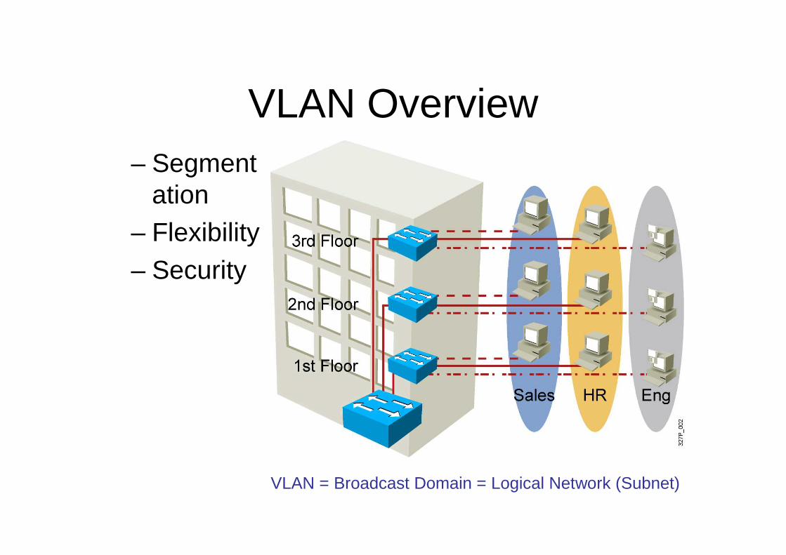
VLAN Overview– Segment
ation– Flexibility
– Security
VLAN = Broadcast Domain = Logical Network (Subnet)

Guidelines for Applying IP Address Space
� Allocate one IP subnet per VLAN.� Allocate IP address spaces in contiguous blocks.
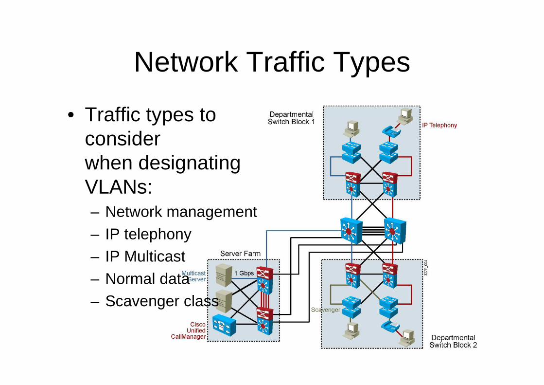
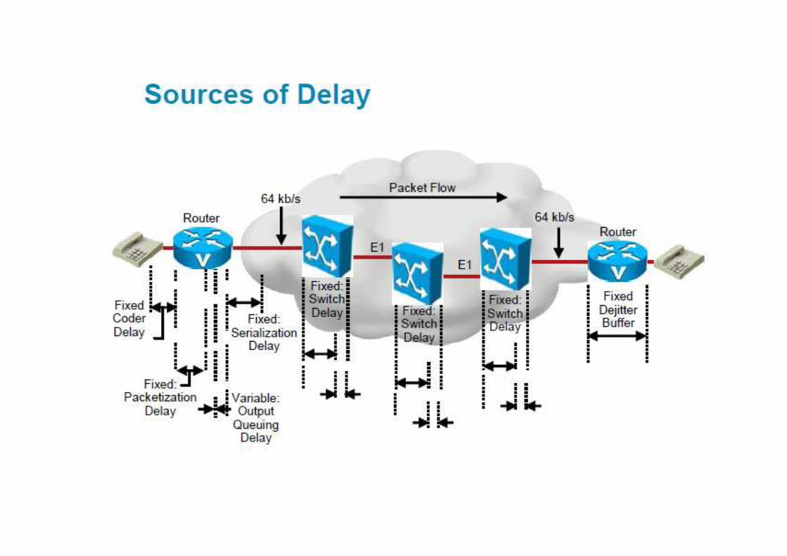
Network Traffic Types
• Traffic types to consider when designating VLANs:– Network management– IP telephony– IP Multicast– Normal data– Scavenger class
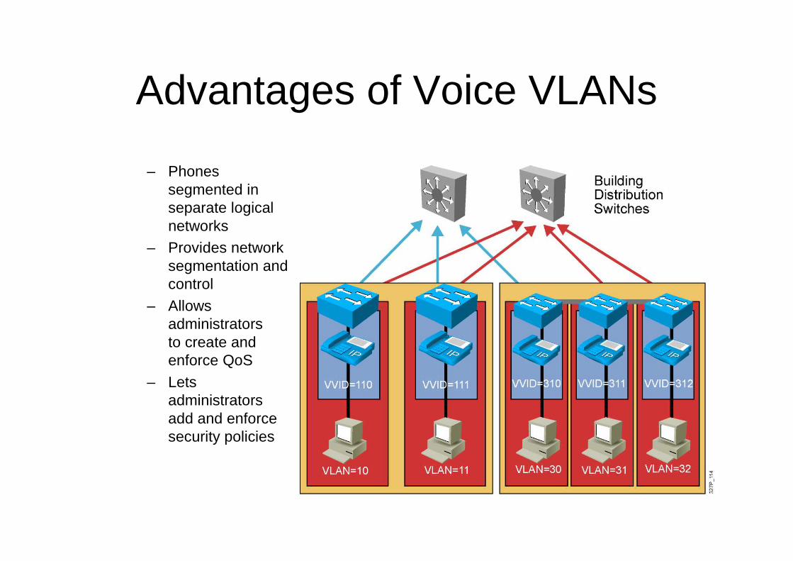
Advantages of Voice VLANs
– Phones segmented in separate logical networks
– Provides network segmentation and control
– Allows administrators to create and enforce QoS
– Lets administrators add and enforce security policies

VLAN Operation
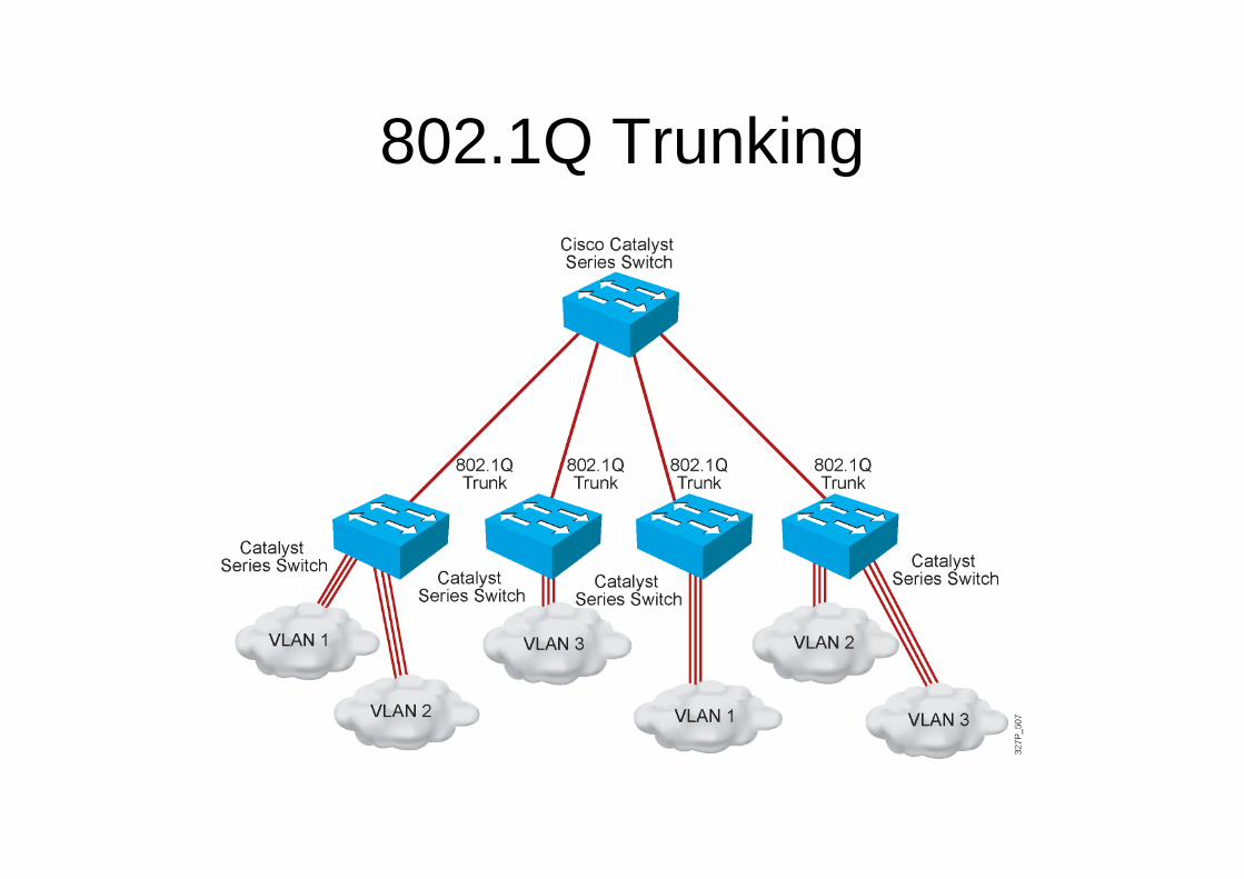
802.1Q Trunking

802.1Q Frame

Understanding Native VLANs

VTP Features

101
� Cannot create, change, or delete VLANs
� Sends and forwards advertisements
� Synchronizes
� Create VLANs
� Modify VLANs
� Delete VLANs
� Sends and forwards advertisements
� Synchronizes
� Create local VLANs only
� Modify local VLANs only
� Delete local VLANs only
� Forwards advertisements
� Does not synchronize
VTP Modes

SwitchX# configure terminalSwitchX(config)# vtp mode [ server | client | transparent ]SwitchX(config)# vtp domain domain-nameSwitchX(config)# vtp password passwordSwitchX(config)# end
Creating a VTP Domain

SwitchX(config)# vtp domain IIUCChanging VTP domain name to IIUCSwitchX(config)# vtp mode transparentSetting device to VTP TRANSPARENT mode.SwitchX(config)# end
SwitchX# show vtp statusVTP Version : 2Configuration Revision : 0Maximum VLANs supported locally : 64Number of existing VLANs : 17VTP Operating Mode : TransparentVTP Domain Name : IIUCVTP Pruning Mode : DisabledVTP V2 Mode : DisabledVTP Traps Generation : DisabledMD5 digest : 0x7D 0x6E 0x5E 0x3D 0xAF 0xA0 0x2F 0xAAConfiguration last modified by 10.1.1.4 at 3-3-93 20:08:05SwitchX#
VTP Configuration and Verification Example

Configuring 802.1Q Trunking
� Configures the port as a VLAN trunk
SwitchX(config-if)#
switchport mode trunk
switchport mode {access | dynamic {auto | desirable} | trunk}
SwitchX(config-if)#
� Configures the trunking characteristics of the port

105
SwitchX# show interfaces fa0/11 trunk
Port Mode Encapsulation Status Native vlanFa0/11 desirable 802.1q trunking 1
Port Vlans allowed on trunkFa0/11 1-4094
Port Vlans allowed and active in management domainFa0/11 1-13
SwitchX# show interfaces fa0/11 switchportName: Fa0/11Switchport: EnabledAdministrative Mode: trunkOperational Mode: downAdministrative Trunking Encapsulation: dot1qNegotiation of Trunking: OnAccess Mode VLAN: 1 (default)Trunking Native Mode VLAN: 1 (default). . .
Verifying a TrunkSwitchX# show interfaces interface [switchport | trunk]
106
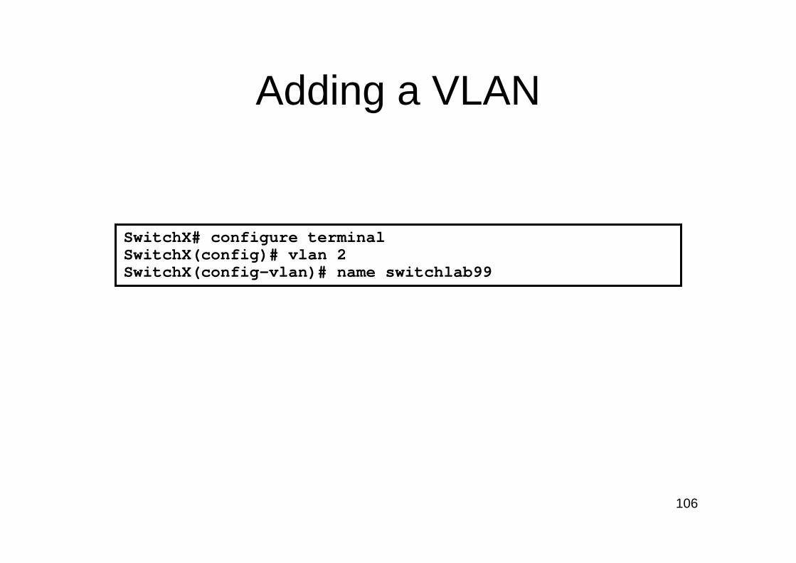
Adding a VLAN
SwitchX# configure terminalSwitchX(config)# vlan 2SwitchX(config-vlan)# name switchlab99
107
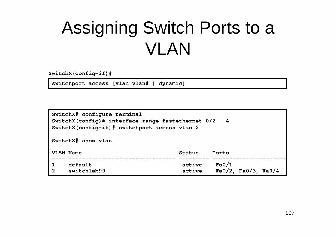
Assigning Switch Ports to a VLAN
SwitchX# configure terminalSwitchX(config)# interface range fastethernet 0/2 - 4SwitchX(config-if)# switchport access vlan 2
SwitchX# show vlan
VLAN Name Status Ports---- -------------------------------- --------- ----------------------1 default active Fa0/1 2 switchlab99 active Fa0/2, Fa0/3, Fa0/4
switchport access [vlan vlan# | dynamic]
SwitchX(config-if)#

108
Verifying VLAN Membership (Cont.)
SwitchX# show interfaces fa0/2 switchportName: Fa0/2Switchport: EnabledAdministrative Mode: dynamic autoOperational Mode: static accessAdministrative Trunking Encapsulation: dot1qOperational Trunking Encapsulation: nativeNegotiation of Trunking: OnAccess Mode VLAN: 2 (switchlab99)Trunking Native Mode VLAN: 1 (default)--- output omitted ----
show interfaces interface switchport
SwitchX(config-if)#

Loop Resolution with STP
– Provides a loop-free redundant network topology by placing certain ports in the blocking state
– Published in the IEEE 802.1D specification– Enhanced with the Cisco PVST+ implementation
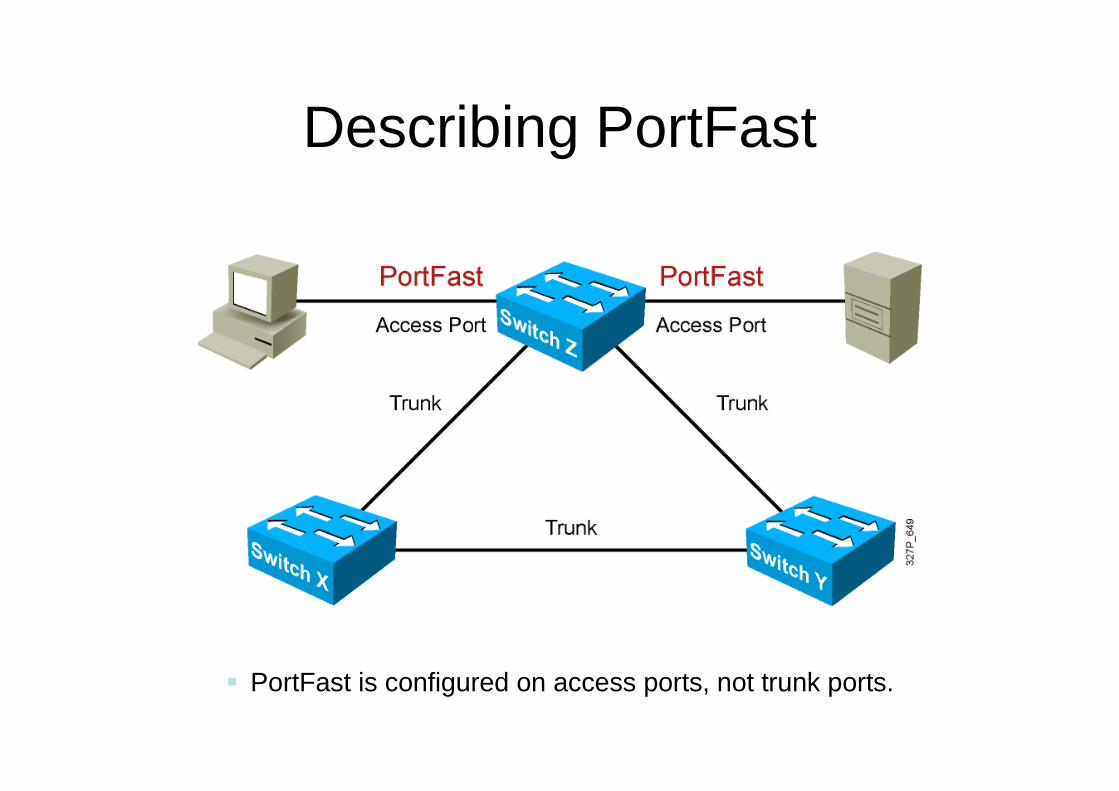
Describing PortFast
� PortFast is configured on access ports, not trunk ports.

Configuring and Verifying PortFast
spanning-tree portfast
SwitchX(config-if)#
� Configures PortFast on an interface
spanning-tree portfast default
SwitchX(config)#
� Enables PortFast on all nontrunking interfaces
show running-config interface interface
SwitchX#
� Verifies that PortFast has been configured on an interface
OR

VLAN-to-VLAN Overview
� Network layer devices combine multiple broadcast domains.

Dividing a Physical Interface into Subinterfaces
� Physical interfaces can be divided into multiple subinterfaces.

Routing Between VLANs with 802.1Q Trunks
interface fastethernet 0/0ip address 10.1.1.1 255.255.255.0encapsulation dot1q 1 native
interface fastethernet 0/0.2ip address 10.2.2.1 255.255.255.0encapsulation dot1q 2
© 2008 Cisco Systems, Inc. All rights reserved. CIPT1 v6.0—3-4
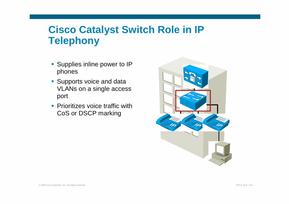
Cisco Catalyst Switch Role in IP Telephony
� Supplies inline power to IP phones
� Supports voice and data VLANs on a single access port
� Prioritizes voice traffic with CoS or DSCP marking

© 2008 Cisco Systems, Inc. All rights reserved. CIPT1 v6.0—3-5
Applying Switch Features
Switch Features When to Use How to Use
PoEWhen you require the
reliability, availability and flexibility of PoE
Identify the PoE type required. PoE is enabled
by default.
Voice VLAN
When you want to connect a PC to an IP phone and have both using a single
physical port at the switch but with separate VLANs
Configure voice VLAN in addition to access VLAN.
QoS / CoS
When you want to ensure that voice quality is not
affected by network traffic congestion
Identify the trust boundary and the applications.
Configure the QoS base for your traffic requirements.

© 2008 Cisco Systems, Inc. All rights reserved. CIPT1 v6.0—3-6
Cisco Catalyst Family of Switches
Cisco Catalyst 3560
Cisco Catalyst 3750
Cisco Catalyst 6500 Cisco Catalyst 4500
Cisco EtherSwitch Network Module

YesYesYesYesYesCisco Prestandard PoE
NoYesYesYesYes802.3af-Compliant
16-, 36-port 10/100
24-, 48-port 10/100
24-, 48-port 10/100
48-port 10/100 or10/100/1000
48-, 96-port 10/100 or 48-port 10/100/1000
PoEConfiguration Options
Cisco EtherSwitchModule
Cisco Catalyst 3560
Cisco Catalyst 3750
Cisco Catalyst 4500
Cisco Catalyst 6500

© 2008 Cisco Systems, Inc. All rights reserved. CIPT1 v6.0—3-8
Three Ways to Power Cisco IP Phones
� Power over Ethernet (PoE):
– Needs PoE line cards or PoE ports for Cisco Catalyst switches
– Delivers 48V DC over data pairs (pins 1, 2, 3, and 6) or spare pairs (pins 4, 5, 7, 8)
� Midspan power injection:
– Needs external power source equipment
– Delivers 48V DC over spare pairs
� Wall power:
– Needs DC converter to connect a Cisco IP phone to a wall outlet
110 V AC Wall Power to 48 V DC Converter
AC Source
No PowerPower Injector
Power
Power

© 2008 Cisco Systems, Inc. All rights reserved. CIPT1 v6.0—3-9
Two Types of PoE Delivery
Cisco original implementation:� Provides -48V DC at up to 6.3 to 7.7 W per port over data pins
1, 2, 3, and 6.
� Supports most Cisco devices (Cisco IP phones and wireless accesspoints).
� Uses a Cisco proprietary method of determining if an attached device requires power. Power is delivered only to devices that require power.
IEEE 802.3af Power over Ethernet:� Specifies 48V DC at up to 15.4W per port over data pins 1, 2, 3, and 6 or
spare pins 4, 5, 7, and 8.
� Enables a new range of Ethernet-powered devices because of increased power.
� Standardizes the method of determining if an attached device requires power. Power is delivered only to devices that require power.
� Has several optional elements, including power classification.
© 2008 Cisco Systems, Inc. All rights reserved. CIPT1 v6.0—3-10
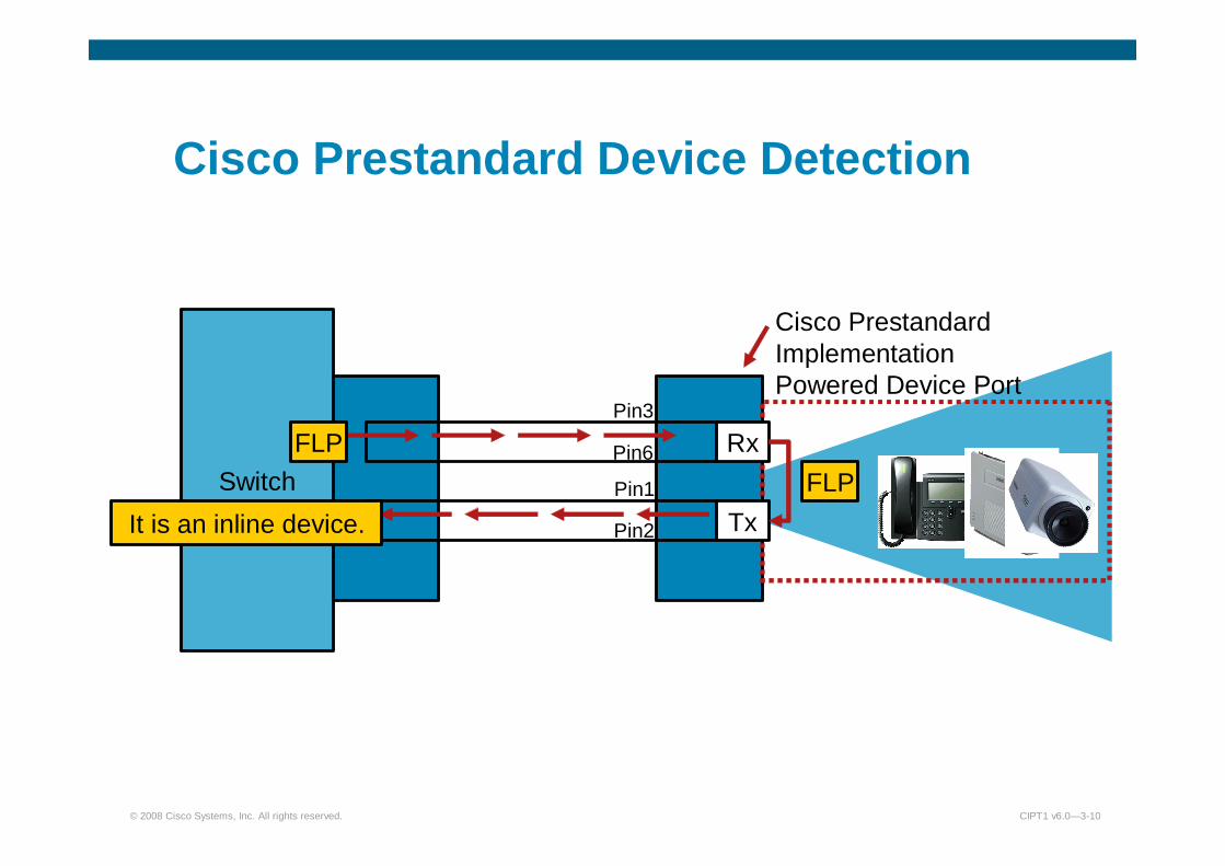
Cisco Prestandard Device Detection
Switch
Cisco PrestandardImplementationPowered Device Port
Rx
Tx
FLP
FLP
It is an inline device.
Pin3
Pin6
Pin1
Pin2

© 2008 Cisco Systems, Inc. All rights reserved. CIPT1 v6.0—3-11
IEEE 802.3af Device Detection
Switch
IEEE 802.3af Powered Device
Rx
Tx
Detect Voltage 25K Ohm Resistor
It is an IEEE powered device.
Pin3
Pin6
Pin1
Pin2
2.8V to 10V
IEEE 802.3af PSE

© 2008 Cisco Systems, Inc. All rights reserved. CIPT1 v6.0—3-13
Cisco Catalyst Switch: Configuring PoE
Cisco Catalyst Operating System:CatOS>(enable) set port inlinepower <mod/port> ?
auto Port inline power auto modeoff Port inline power off mode
Native Cisco IOS Software:CSCOIOS(config-if)# power inline <auto/never>
© 2008 Cisco Systems, Inc. All rights reserved. CIPT1 v6.0—3-14
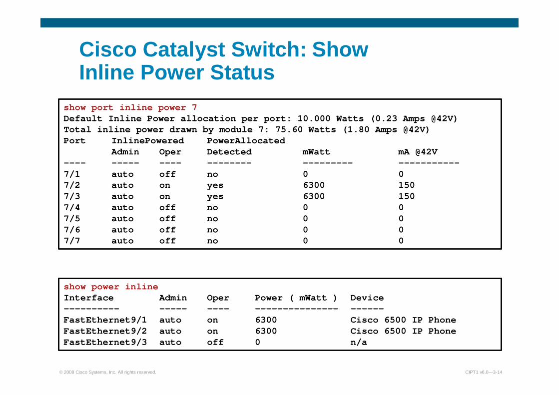
Cisco Catalyst Switch: Show Inline Power Status
show port inline power 7Default Inline Power allocation per port: 10.000 Watts (0.23 Amps @42V) Total inline power drawn by module 7: 75.60 Watts (1.80 Amps @42V) Port InlinePowered PowerAllocated
Admin Oper Detected mWatt mA @42V ---- ----- ---- -------- --------- -----------7/1 auto off no 0 0 7/2 auto on yes 6300 150 7/3 auto on yes 6300 150 7/4 auto off no 0 0 7/5 auto off no 0 0 7/6 auto off no 0 0 7/7 auto off no 0 0
show power inline Interface Admin Oper Power ( mWatt ) Device---------- ----- ---- --------------- ------FastEthernet9/1 auto on 6300 Cisco 6500 IP PhoneFastEthernet9/2 auto on 6300 Cisco 6500 IP PhoneFastEthernet9/3 auto off 0 n/a

© 2008 Cisco Systems, Inc. All rights reserved. CIPT1 v6.0—3-16
Cisco IP Phone Connected to the Network
P0
P1P2P
Integrated 3-Port Switch
© 2008 Cisco Systems, Inc. All rights reserved. CIPT1 v6.0—3-17
Voice VLAN Support
� A Cisco Catalyst switch can be configured to support voice traffic in various ways:– Single VLAN access port
– Multi-VLAN access port– Trunk port
� Considerations:
– Security– Cisco IP phones/non-Cisco IP phones/IP softphones– Spanning tree
– QoS

© 2008 Cisco Systems, Inc. All rights reserved. CIPT1 v6.0—3-18
Single VLAN Access Port
� An access port configured for one VLAN only
� Typically used for non-Cisco IP phones or softphones
– Non-Cisco IP phones: Use voice VLAN for access port
– Softphones: Use data VLAN for access port and allow required IP communication to voice VLAN (IP ACLs)
� If used with Cisco IP phones:
– Not recommended with PC attached
– If no PC attached: Use voice VLAN for access port
� Voice can be tagged with 802.1p (VLAN ID=0) or untagged
Access Port
Untagged 802.3
Untagged or 802.1p

© 2008 Cisco Systems, Inc. All rights reserved. CIPT1 v6.0—3-19
Multi-VLAN Access Port
� An access port able to handle two VLANs
– Access (data) VLAN and voice (auxiliary) VLAN� Voice traffic is tagged with 802.1Q VLAN ID
– Data traffic is untagged and is forwarded by IP to and from PC port.
– Phone can be hardened to prevent PC from seeing the voice traffic (by default, phone acts like a hub).
– Best choice with Cisco IP phones.– Voice VLAN does not need to be configured on IP phone but can be
learned from Cisco Discovery Protocol messages sent out by the switch.
Access Port
Untagged 802.3
Tagged 802.1Q

© 2008 Cisco Systems, Inc. All rights reserved. CIPT1 v6.0—3-20
Trunk Ports
� A trunk port is able to handle multiple VLANs.
� Usually data traffic is untagged and put into a native VLAN.� Data traffic can be tagged with any 802.1Q VLAN ID if supported by PC
(and permitted by IP phone).� A voice VLAN does not need to be configured on IP phone but can be
learned from Cisco Discovery Protocol messages sent out by the switch.� Security considerations:
– Cannot be configured as secure port
– If allowed VLANs are not limited, PC has access to all VLANs of the switch
Trunk Port
Untagged 802.3 (Native VLAN)
Tagged 802.1Q
© 2008 Cisco Systems, Inc. All rights reserved. CIPT1 v6.0—3-22
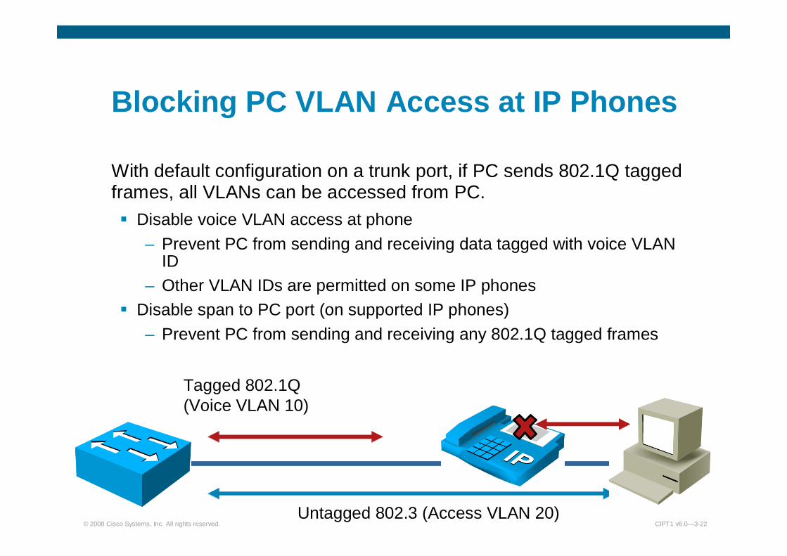
Blocking PC VLAN Access at IP Phones
With default configuration on a trunk port, if PC sends 802.1Q tagged frames, all VLANs can be accessed from PC.� Disable voice VLAN access at phone
– Prevent PC from sending and receiving data tagged with voice VLAN ID
– Other VLAN IDs are permitted on some IP phones� Disable span to PC port (on supported IP phones)
– Prevent PC from sending and receiving any 802.1Q tagged frames
Untagged 802.3 (Access VLAN 20)
Tagged 802.1Q (Voice VLAN 10)
© 2008 Cisco Systems, Inc. All rights reserved. CIPT1 v6.0—3-23
Limiting VLANs on Trunk Ports at the Switch
� VLANs allowed on a trunk port can be configured at the switch.
� Recommendation is to only allow native VLAN and voice VLAN.
– Blocks PC access to all other VLANs, independent of IP phone configuration and model
– Access to voice VLAN, can only be prevented by IP phone configuration but is supported on all IP phone models with PC ports
– Improves performance
– Improves stability – Minimizes STP issues

© 2008 Cisco Systems, Inc. All rights reserved. CIPT1 v6.0—3-25
Configuring Voice VLANs in Access PortUsing Native Cisco IOS Software
Example 1 (single VLAN access port):
Console(config)#interface FastEthernet0/1 Console(config-if)#switchport mode access Console(config-if)#switchport voice vlan dot1pConsole(config-if)#switchport access vlan 261
Example 2 (multi-VLAN access port):
Console(config)#interface FastEthernet0/1 Console(config-if)#switchport mode access Console(config-if)#switchport voice vlan 261Console(config-if)#switchport access vlan 262
© 2008 Cisco Systems, Inc. All rights reserved. CIPT1 v6.0—3-26
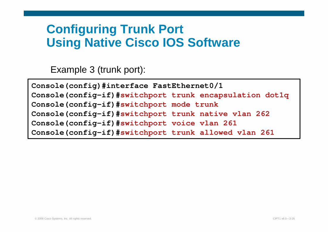
Configuring Trunk PortUsing Native Cisco IOS Software
Example 3 (trunk port):
):Console(config)#interface FastEthernet0/1 Console(config-if)#switchport trunk encapsulation dot1q Console(config-if)#switchport mode trunkConsole(config-if)#switchport trunk native vlan 262Console(config-if)#switchport voice vlan 261Console(config-if)#switchport trunk allowed vlan 261
© 2008 Cisco Systems, Inc. All rights reserved. CIPT1 v6.0—3-27
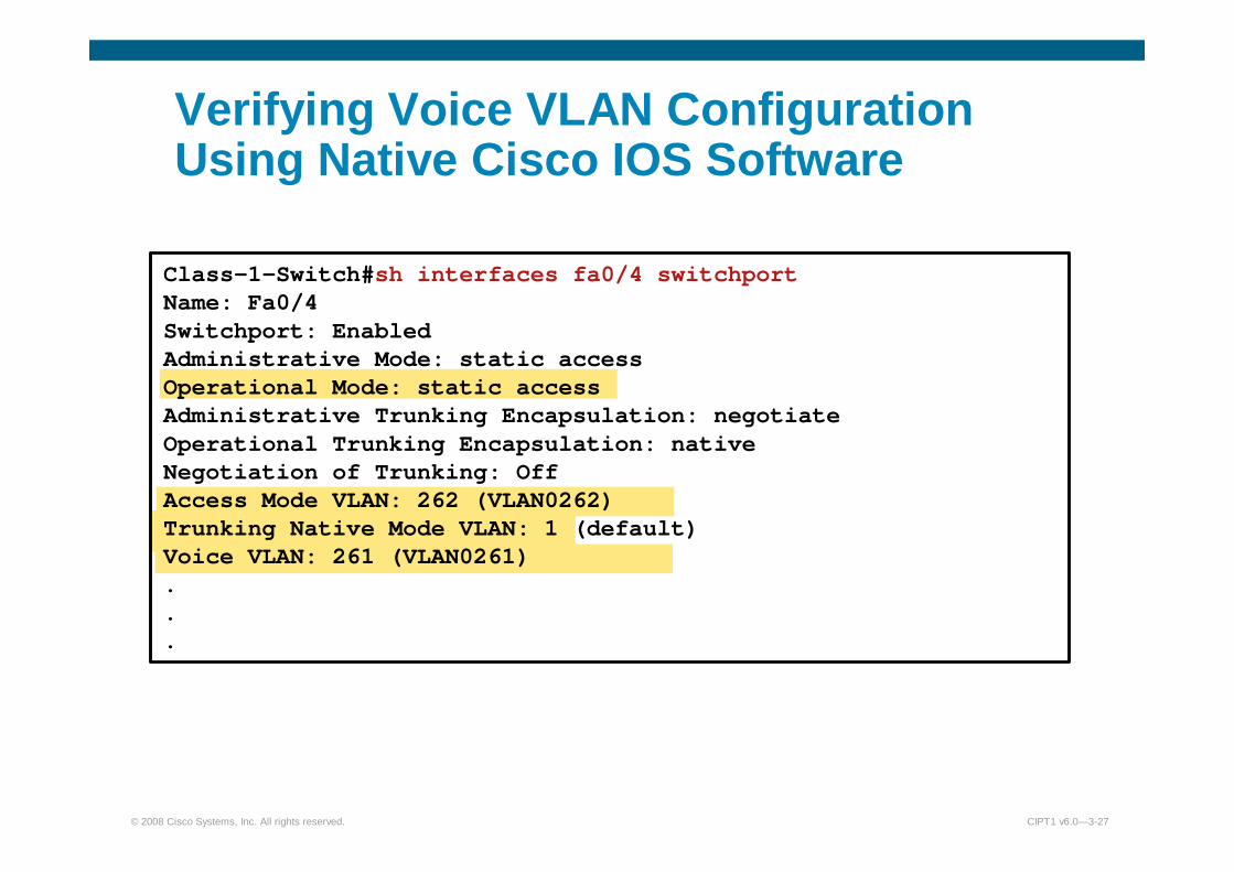
Verifying Voice VLAN Configuration Using Native Cisco IOS Software
Class-1-Switch#sh interfaces fa0/4 switchportName: Fa0/4 Switchport: Enabled Administrative Mode: static access Operational Mode: static access Administrative Trunking Encapsulation: negotiate Operational Trunking Encapsulation: native Negotiation of Trunking: Off Access Mode VLAN: 262 (VLAN0262) Trunking Native Mode VLAN: 1 (default) Voice VLAN: 261 (VLAN0261) ...

© 2008 Cisco Systems, Inc. All rights reserved. CIPT1 v6.0—3-29
Configuring Voice VLANsUsing Cisco Catalyst Operating System
Example 1 (single VLAN access port):
Console>(enable) set port auxiliaryvlan 2/1-3 dot1p Console>(enable) set vlan 262 2/1-3Console>(enable) set trunk 2/1-3 off
Example 2 (multi-VLAN access port):
Console>(enable) set port auxiliaryvlan 2/1-3 261 Console>(enable) set vlan 262 2/1-3Console>(enable) set trunk 2/1-3 off

© 2008 Cisco Systems, Inc. All rights reserved. CIPT1 v6.0—3-30
Configuring Trunk Ports Using Cisco Catalyst Operating System
Example 3 (trunk port):
):Console>(enable) set trunk 2/1-3 on Console>(enable) clear trunk 2/1-3 1-4096Console>(enable) set vlan 262 2/1-3Console>(enable) set port auxiliaryvlan 261 2/1-3Console>(enable) set trunk 261 2/1-3

© 2008 Cisco Systems, Inc. All rights reserved. CIPT1 v6.0—3-31
Verifying Voice VLAN Configuration Using Cisco Catalyst Operating System
Console> (enable)show port auxiliaryvlan 222AuxiliaryVlan AuxVlanStatus Mod/Ports------------- ------------- ----------222 active 1/2,2/1-3
Console> (enable)show port 2/1...Port AuxiliaryVlan AuxVlan-Status----- ------------- --------------2/1 222 active
...