Embed Size (px)
Citation preview
GB
Valid for serial no. 827-xxx-xxxx0460 474 074 100217
Tradestig 150Tradestig 220
Instruction manual and spare parts list
- 2 -TOCe
Rights reserved to alter specifications without notice.
1 DIRECTIVE 3. . . . . . . . . . . . . . . . . . . . . . . . . . . . . . . . . . . . . . . . . . . . . . . . . . . . . . . .
2 SAFETY 3. . . . . . . . . . . . . . . . . . . . . . . . . . . . . . . . . . . . . . . . . . . . . . . . . . . . . . . . . . .
3 INTRODUCTION 5. . . . . . . . . . . . . . . . . . . . . . . . . . . . . . . . . . . . . . . . . . . . . . . . . . .
4 TECHNICAL DATA 5. . . . . . . . . . . . . . . . . . . . . . . . . . . . . . . . . . . . . . . . . . . . . . . . .
5 INSTALLATION 7. . . . . . . . . . . . . . . . . . . . . . . . . . . . . . . . . . . . . . . . . . . . . . . . . . . . 5.1 Location 7. . . . . . . . . . . . . . . . . . . . . . . . . . . . . . . . . . . . . . . . . . . . . . . . . . . . . . . . . . . . . . . . . .
5.2 Mains power supply 7. . . . . . . . . . . . . . . . . . . . . . . . . . . . . . . . . . . . . . . . . . . . . . . . . . . . . . . .
6 OPERATION 8. . . . . . . . . . . . . . . . . . . . . . . . . . . . . . . . . . . . . . . . . . . . . . . . . . . . . . . 6.1 PFC - Power factor correction 8. . . . . . . . . . . . . . . . . . . . . . . . . . . . . . . . . . . . . . . . . . . . . . .
6.2 Connections and control devices 8. . . . . . . . . . . . . . . . . . . . . . . . . . . . . . . . . . . . . . . . . . . .
6.3 Key to symbols 8. . . . . . . . . . . . . . . . . . . . . . . . . . . . . . . . . . . . . . . . . . . . . . . . . . . . . . . . . . . .
6.4 MMA-welding 9. . . . . . . . . . . . . . . . . . . . . . . . . . . . . . . . . . . . . . . . . . . . . . . . . . . . . . . . . . . . .
6.5 Overheating protection 9. . . . . . . . . . . . . . . . . . . . . . . . . . . . . . . . . . . . . . . . . . . . . . . . . . . . .
6.6 Turning on the power source 9. . . . . . . . . . . . . . . . . . . . . . . . . . . . . . . . . . . . . . . . . . . . . . . .
7 CONTROL PANELS 9. . . . . . . . . . . . . . . . . . . . . . . . . . . . . . . . . . . . . . . . . . . . . . . . 7.1 Tradestig 150 10. . . . . . . . . . . . . . . . . . . . . . . . . . . . . . . . . . . . . . . . . . . . . . . . . . . . . . . . . . . . .
7.2 Tradestig 220 11. . . . . . . . . . . . . . . . . . . . . . . . . . . . . . . . . . . . . . . . . . . . . . . . . . . . . . . . . . . . .
8 TIG WELDING 12. . . . . . . . . . . . . . . . . . . . . . . . . . . . . . . . . . . . . . . . . . . . . . . . . . . . . 8.1 Settings 12. . . . . . . . . . . . . . . . . . . . . . . . . . . . . . . . . . . . . . . . . . . . . . . . . . . . . . . . . . . . . . . . . .
8.2 Symbol and Function explanations TIG 12. . . . . . . . . . . . . . . . . . . . . . . . . . . . . . . . . . . . . . .
8.3 Hidden TIG functions 16. . . . . . . . . . . . . . . . . . . . . . . . . . . . . . . . . . . . . . . . . . . . . . . . . . . . . .
9 MMA WELDING 17. . . . . . . . . . . . . . . . . . . . . . . . . . . . . . . . . . . . . . . . . . . . . . . . . . . . 9.1 Settings 17. . . . . . . . . . . . . . . . . . . . . . . . . . . . . . . . . . . . . . . . . . . . . . . . . . . . . . . . . . . . . . . . . .
9.2 Symbol and Function explanations MMA 17. . . . . . . . . . . . . . . . . . . . . . . . . . . . . . . . . . . . . .
9.3 Hidden MMA functions 18. . . . . . . . . . . . . . . . . . . . . . . . . . . . . . . . . . . . . . . . . . . . . . . . . . . . .
10 WELDING DATA MEMORY 19. . . . . . . . . . . . . . . . . . . . . . . . . . . . . . . . . . . . . . . . . .
11 FAULT CODES 19. . . . . . . . . . . . . . . . . . . . . . . . . . . . . . . . . . . . . . . . . . . . . . . . . . . .
12 MAINTENANCE 20. . . . . . . . . . . . . . . . . . . . . . . . . . . . . . . . . . . . . . . . . . . . . . . . . . . . 12.1 Inspection and cleaning 20. . . . . . . . . . . . . . . . . . . . . . . . . . . . . . . . . . . . . . . . . . . . . . . . . . . .
13 FAULT-TRACING 20. . . . . . . . . . . . . . . . . . . . . . . . . . . . . . . . . . . . . . . . . . . . . . . . . .
14 ORDERING SPARE PARTS 21. . . . . . . . . . . . . . . . . . . . . . . . . . . . . . . . . . . . . . . . .
15 DISMANTLING AND SCRAPPING 21. . . . . . . . . . . . . . . . . . . . . . . . . . . . . . . . . . .
DIAGRAM 22. . . . . . . . . . . . . . . . . . . . . . . . . . . . . . . . . . . . . . . . . . . . . . . . . . . . . . . . . . . .
SPARE PARTS LIST 27. . . . . . . . . . . . . . . . . . . . . . . . . . . . . . . . . . . . . . . . . . . . . . . . . .
ACCESSORIES 38. . . . . . . . . . . . . . . . . . . . . . . . . . . . . . . . . . . . . . . . . . . . . . . . . . . . . . .
- 3 -bt35d1ea
1 DIRECTIVE
DECLARATION OF CONFORMITYMurex Welding Products Ltd, EN8 7TF England, gives its unreserved guarantee that welding powersource Tradestig 150 and Tradestig 220 from serial number 827 (2008 w 27) are contructed andtested in compliance with the standard EN 60974-1 /-3 and EN 60974-10 (Class A) in accordance withthe requirements of directive (2006/95/EC) and (2004/108/EEC).-------------------------------------------------------------------
Kent EimbrodtGlobal Director Equipment and Automation
On behalf of Murex Welding Products Ltd.Laxå 2008-08-28
Manufactured by ESAB AB, Welding Equipment
SE-695 81 Laxå Sweden
2 SAFETY
Users of welding equipment have the ultimate responsibility for ensuring that anyone who works onor near the equipment observes all the relevant safety precautions. Safety precautions must meetthe requirements that apply to this type of welding equipment. The following recommendationsshould be observed in addition to the standard regulations that apply to the workplace.
All work must be carried out by trained personnel well-acquainted with the operation of the weldingequipment. Incorrect operation of the equipment may lead to hazardous situations which can resultin injury to the operator and damage to the equipment.
1. Anyone who uses the welding equipment must be familiar with:� its operation� location of emergency stops� its function� relevant safety precautions� welding
2. The operator must ensure that:� no unauthorized person is stationed within the working area of the equipment when it is
started up.� no-one is unprotected when the arc is struck
3. The workplace must:� be suitable for the purpose� be free from drafts
4. Personal safety equipment� Always wear recommended personal safety equipment, such as safety glasses, flame-proof
clothing, safety gloves. Note! Do not use safety gloves when replacing wire.� Do not wear loose-fitting items, such as scarves, bracelets, rings, etc., which could become
trapped or cause burns.
5. General precautions� Make sure the return cable is connected securely.� Work on high voltage equipment may only be carried out by a qualified electrician.� Appropriate fire extinquishing equipment must be clearly marked and close at hand.� Lubrication and maintenance must not be carried out on the equipment during operation.
GB
- 4 -bt35d1ea
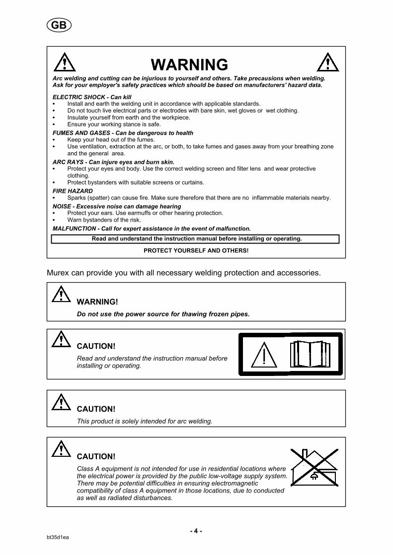
WARNING
Read and understand the instruction manual before installing or operating.
Arc welding and cutting can be injurious to yourself and others. Take precausions when welding.Ask for your employer's safety practices which should be based on manufacturers' hazard data.
ELECTRIC SHOCK - Can kill� Install and earth the welding unit in accordance with applicable standards.� Do not touch live electrical parts or electrodes with bare skin, wet gloves or wet clothing.� Insulate yourself from earth and the workpiece.� Ensure your working stance is safe.
FUMES AND GASES - Can be dangerous to health� Keep your head out of the fumes.� Use ventilation, extraction at the arc, or both, to take fumes and gases away from your breathing zone
and the general area.
ARC RAYS - Can injure eyes and burn skin.� Protect your eyes and body. Use the correct welding screen and filter lens and wear protective
clothing.� Protect bystanders with suitable screens or curtains.
FIRE HAZARD� Sparks (spatter) can cause fire. Make sure therefore that there are no inflammable materials nearby.
NOISE - Excessive noise can damage hearing� Protect your ears. Use earmuffs or other hearing protection.� Warn bystanders of the risk.
MALFUNCTION - Call for expert assistance in the event of malfunction.
PROTECT YOURSELF AND OTHERS!
Murex can provide you with all necessary welding protection and accessories.
WARNING!
Do not use the power source for thawing frozen pipes.
CAUTION!
Read and understand the instruction manual beforeinstalling or operating.
CAUTION!
This product is solely intended for arc welding.
CAUTION!
Class A equipment is not intended for use in residential locations wherethe electrical power is provided by the public low-voltage supply system.There may be potential difficulties in ensuring electromagneticcompatibility of class A equipment in those locations, due to conductedas well as radiated disturbances.
GB

- 5 -bt35d1ea
3 INTRODUCTION
The Tradestig 150 / Tradestig 220 is a TIG welding power source, which can alsobe used for MMA welding. It can be used direct current (DC).
MUREX's accessories for the product can be found on page 38.
Equipment
The power source is supplied with a 3 m welding cable, 3 m return cable, 3 m mainscable, instruction manual for power source and control panel.
Control panels
Tradestig 150 Tradestig 220
When mains power is supplied the unit runs a self diagnosis of theLEDs and the display, the program version is displayed and in thisexample the program version is 0.18.
The manual describes the use of Tradestig 150 and Tradestig 220 control panel onpage 9.
For general information about operation and connection, see page 8
4 TECHNICAL DATA
Tradestig 150 Tradestig 220
Mains voltage 230V, �10%, 1 50/60 Hz 230V, �10%, 1 50/60 Hz
Mains supply Zmax 0.35 ohm Zmax 0.31 ohm
Primary current Imax TIGImax MMA
14 A22 A
24 A25 A
No-load power demand when in the energy-savingmode, 6.5 min. after welding
30 W 30 W
Setting range TIGMMA
3 - 150 A4 - 150 A
3 - 220 A4 - 170 A
GB
- 6 -bt35d1ea
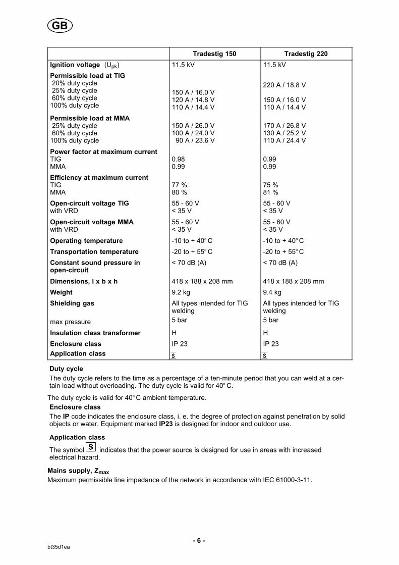
Tradestig 220Tradestig 150
Ignition voltage (Upk) 11.5 kV 11.5 kV
Permissible load at TIG 20% duty cycle 25% duty cycle 60% duty cycle100% duty cycle
150 A / 16.0 V 120 A / 14.8 V110 A / 14.4 V
220 A / 18.8 V
150 A / 16.0 V110 A / 14.4 V
Permissible load at MMA 25% duty cycle 60% duty cycle100% duty cycle
150 A / 26.0 V 100 A / 24.0 V 90 A / 23.6 V
170 A / 26.8 V 130 A / 25.2 V110 A / 24.4 V
Power factor at maximum currentTIGMMA
0.98 0.99
0.99 0.99
Efficiency at maximum currentTIGMMA
77 % 80 %
75 % 81 %
Open-circuit voltage TIGwith VRD
55 - 60 V< 35 V
55 - 60 V< 35 V
Open-circuit voltage MMAwith VRD
55 - 60 V< 35 V
55 - 60 V< 35 V
Operating temperature -10 to + 40°C -10 to + 40°C
Transportation temperature -20 to + 55°C -20 to + 55°C
Constant sound pressure inopen-circuit
< 70 dB (A) < 70 dB (A)
Dimensions, l x b x h 418 x 188 x 208 mm 418 x 188 x 208 mm
Weight 9.2 kg 9.4 kg
Shielding gas
max pressure
All types intended for TIGwelding
5 bar
All types intended for TIGwelding
5 bar
Insulation class transformer H H
Enclosure class IP 23 IP 23
Application class
Duty cycle
The duty cycle refers to the time as a percentage of a ten-minute period that you can weld at a certain load without overloading. The duty cycle is valid for 40°C.
The duty cycle is valid for 40°C ambient temperature.
Enclosure class
The IP code indicates the enclosure class, i. e. the degree of protection against penetration by solidobjects or water. Equipment marked IP23 is designed for indoor and outdoor use.
Application class
The symbol indicates that the power source is designed for use in areas with increasedelectrical hazard.
Mains supply, Zmax
Maximum permissible line impedance of the network in accordance with IEC 61000-3-11.
GB
- 7 -bt35d1ea
5 INSTALLATION
The installation must be executed by a professional.
Note!
Mains supply requirements
High power equipment may, due to the primary current drawn from the mains supply, influence thepower quality of the grid. Therefore connection restrictions or requirements regarding themaximum permissible mains impedance or the required minimum supply capacity at the interfacepoint to the public grid may apply for some types of equipment (see technical data). In this case itis the responsibility of the installer or user of the equipment to ensure, by consultation with thedistrubution network operator if necessary, that the equipment may be connected.
5.1 Location
Position the welding power source such that its cooling air inlets and outlets are notobstructed.
5.2 Mains power supply
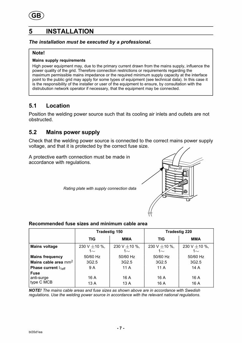
Check that the welding power source is connected to the correct mains power supplyvoltage, and that it is protected by the correct fuse size.
A protective earth connection must be made in accordance with regulations.
Rating plate with supply connection data
Recommended fuse sizes and minimum cable area
Tradestig 150 Tradestig 220
TIG MMA TIG MMA
Mains voltage 230 V �10 %,1�
230 V �10 %,1�
230 V �10 %,1�
230 V �10 %,1�
Mains frequency 50/60 Hz 50/60 Hz 50/60 Hz 50/60 Hz
Mains cable area mm2 3G2.5 3G2.5 3G2.5 3G2.5
Phase current I1eff 9 A 11 A 11 A 14 A
Fuse anti-surgetype C MCB
16 A
13 A
16 A
13 A
16 A
16 A
16 A
16 A
NOTE! The mains cable areas and fuse sizes as shown above are in accordance with Swedishregulations. Use the welding power source in accordance with the relevant national regulations.
GB
- 8 -bt35d1ea
6 OPERATION
General safety regulations for the handling of the equipment can be found onpage 3. Read through before you start using the equipment!
6.1 PFC - Power factor correction
The Tradestig is 230 V single-phase power sources equipped with a PFC circuitmaking it possible to use the full range of the machine on a 16 A fuse. The PFC alsoprotects the machines against fluctuating mains voltage and makes it safer to usewith a generator. Tradestig can operate with extra long mains cables, over 100 m,giving you a very larger working radius.
6.2 Connections and control devices
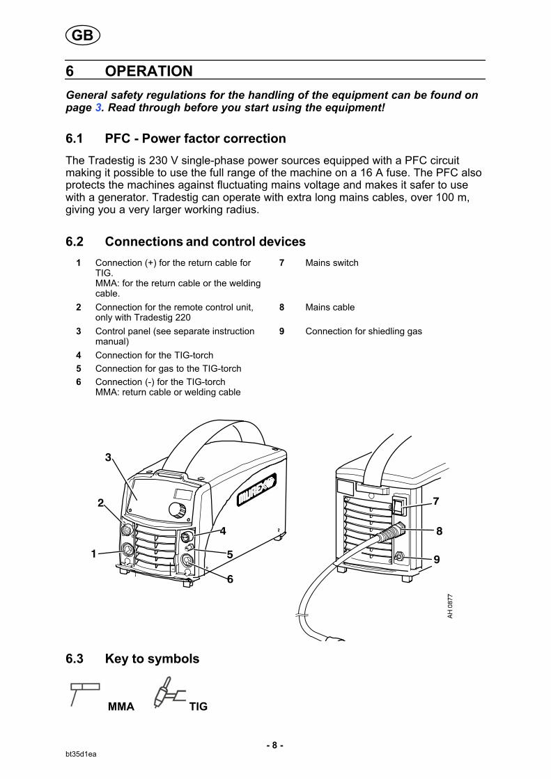
1 Connection (+) for the return cable forTIG. MMA: for the return cable or the weldingcable.
7 Mains switch
2 Connection for the remote control unit,only with Tradestig 220
8 Mains cable
3 Control panel (see separate instructionmanual)
9 Connection for shiedling gas
4 Connection for the TIG-torch
5 Connection for gas to the TIG-torch
6 Connection (-) for the TIG-torchMMA: return cable or welding cable
6.3 Key to symbols
MMA TIG
GB

- 9 -bt35d1ea
6.4 MMA-welding
Connection of welding and return cable
The welding power source has two terminals, one plus and one minus pole, for the connection of the welding and the return cable. Connect the welding cable to the pole indicated on the package of the electrode to be used.
Connect the return cable to the other terminal. Fit the earth clamp of the return cableto the work-piece and make sure there is good contact between the work-piece and thereturn cable terminal on the welding power source.
6.5 Overheating protection
The power source has two thermal overload trips which operate if the internaltemperature becomes too high. A fault code is shown in the panel. They resetautomatically when the temperature has fallen.
6.6 Turning on the power source
Turn on the mains power by turning the mains switch to the ”1” position.
Turn the unit off by turning the switch to the ”0” position.
Whether the mains power supply is interrupted or the power unit is switched off inthe normal manner, welding data will be stored and is available next time the unit isstarted.
7 CONTROL PANELS
When mains power is supplied the unit runs a self diagnosis of theLEDs and the display, the program version is displayed and in thisexample the program version is 0.18.
VRD (Voltage Reduction Device)
The VRD function ensures that the open-circuit voltage does not exceed 35 V whenwelding is not being carried out. This is indicated by a lit VRD LED. The VRDfunction is deactivated when the system senses that welding has started.
If the VRD function is activated and open-circuit voltage exceeds the 35 V limit, thisis indicated by an error message (16) appearing in the display and welding cannotbe started whilst the error message is displayed.
NOTE! The VRD function is not active (LED has gone out) on delivery. Contact anauthorised ESAB service technician to activate the function.
GB

- 10 -bt35d2ea
7.1 Tradestig 150
Knob for setting data (current (A), time (s) or material thickness (mm/inch))
Display
Choice of welding method TIG or MMA
Choice of selection of HF start or LiftArc� start
Choice of 2-stroke or 4-stroke
Display of VRD function (reduced open-circuit voltage) is active or inactive..
Indication of which parameter is shown in the display, current (A), time (s) or
material thickness (mm/inch)
Choise for selection of setting parameter,
material thickness , slope down or gas post flow .
Note! The pushbutton is also used for hidden functions, see on page 16.
GB

- 11 -bt35d2ea
7.2 Tradestig 220
Knob for setting of current (A) or time (s)
Display
Choice of welding method TIG eller MMA
Choice of TIG- / MMA-welding with direct current or TIG-welding with
pulsed current
Choice of HF start or LiftArc�
Choice of 2-stroke or 4-stroke
Setting from panel , welding data change with torch trigger switch or
connecting remote control unit
Display of VRD-function (reduced open-circuit voltage) is active or inactive.
Indication of which parameter is shown in the display current (A), voltage (V),
time (s)
Choice of current indication (A) or voltage indication (V) during welding, in the
display.
Indication of selected setting parameter, see page 13.
The right-hand button is also used for hidden functions, see page 16 and 18.
Buttoms for weld data memory settings, see page 19.
GB
- 12 -bt35d2ea
8 TIG WELDING
8.1 Settings
Function Setting range Tradestig150
Tradestig220
HF / LiftArc � 2) HF or LiftArc� x x
2/4-stroke 2) 2 stroke or 4 stroke x x
Gas pre flow time 1) 0 - 5 s x x
Slope up-time 1) 0 - 10 s x x
Slope down time 0 - 10 s x x
Gas post flow time 0 - 25 s x x
Current 4 - max 3) x x
Active panel OFF or ON - x
Changing trigger data OFF or ON - x
Remote control unit OFF or ON - x
Min current remote 1) 0-99% - x
Pulse current 4 - max 3) x x
Pulse time
Micro pulse 1)
0.01 - 2.5 s
0.001 - 0.250 s
- x
Background current 4 - max 3) - x
Background time
Micro pulse 1)
0.01 - 2.5 s
0.001 - 0.250 s
- x
Material thickness 3) 30 A/mm in step of 0.1 mm x -
1) These functions are hidden Tig functions, see description point 8.3.2) These functions cannot be changed while welding is in progress3) The setting range is depended on the power source used.
8.2 Symbol and Function explanations TIG
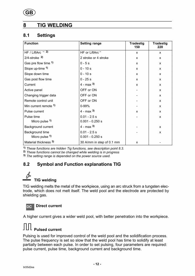
TIG welding
TIG welding melts the metal of the workpiece, using an arc struck from a tungsten electrode, which does not melt itself. The weld pool and the electrode are protected byshielding gas.
Direct current
A higher current gives a wider weld pool, with better penetration into the workpiece.
Pulsed current
Pulsing is used for improved control of the weld pool and the solidification process.The pulse frequency is set so slow that the weld pool has time to solidify at leastpartially between each pulse. In order to set pulsing, four parameters are required:pulse current, pulse time, background current and background time.
GB
- 13 -bt35d2ea
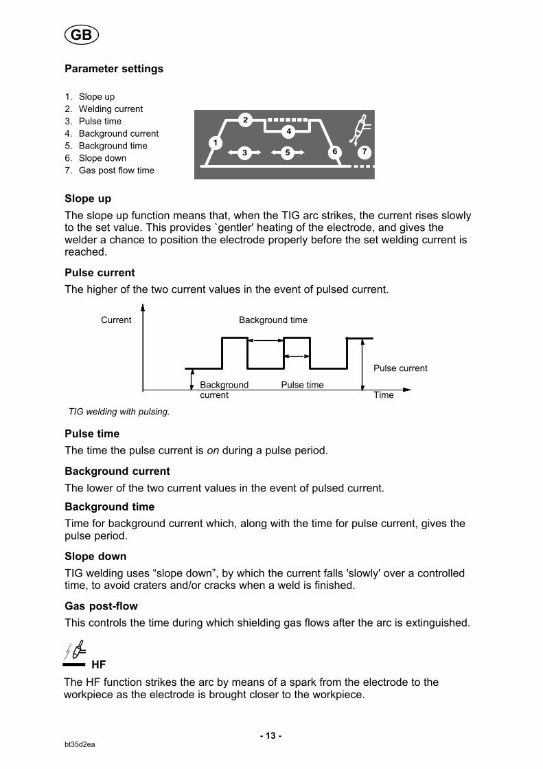
Parameter settings
1. Slope up
2. Welding current
3. Pulse time
4. Background current
5. Background time
6. Slope down
7. Gas post flow time
Slope up
The slope up function means that, when the TIG arc strikes, the current rises slowlyto the set value. This provides `gentler' heating of the electrode, and gives thewelder a chance to position the electrode properly before the set welding current isreached.
Pulse current
The higher of the two current values in the event of pulsed current.
Current Background time
Pulse current
Background current
Pulse timeTime
TIG welding with pulsing.
Pulse time
The time the pulse current is on during a pulse period.
Background current
The lower of the two current values in the event of pulsed current.
Background time
Time for background current which, along with the time for pulse current, gives thepulse period.
Slope down
TIG welding uses “slope down”, by which the current falls 'slowly' over a controlledtime, to avoid craters and/or cracks when a weld is finished.
Gas post-flow
This controls the time during which shielding gas flows after the arc is extinguished.
HF
The HF function strikes the arc by means of a spark from the electrode to theworkpiece as the electrode is brought closer to the workpiece.
GB
- 14 -bt35d2ea
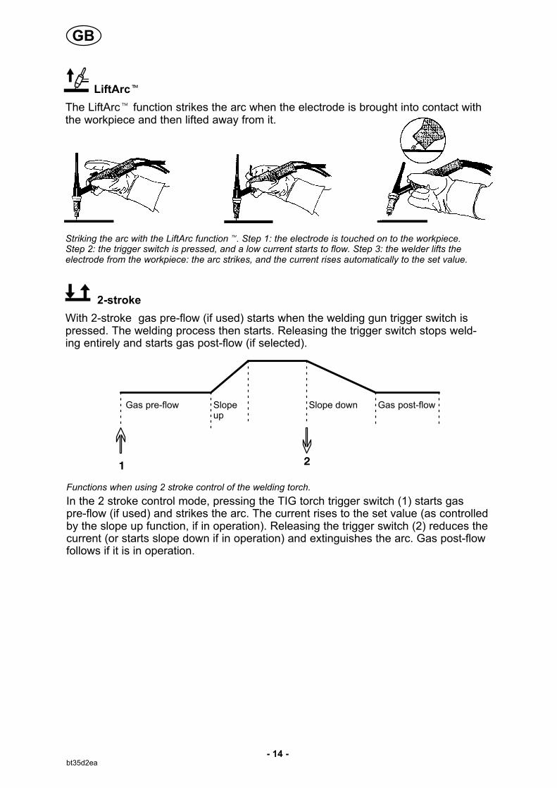
LiftArc�
The LiftArc� function strikes the arc when the electrode is brought into contact withthe workpiece and then lifted away from it.
Striking the arc with the LiftArc function�. Step 1: the electrode is touched on to the workpiece.Step 2: the trigger switch is pressed, and a low current starts to flow. Step 3: the welder lifts theelectrode from the workpiece: the arc strikes, and the current rises automatically to the set value.
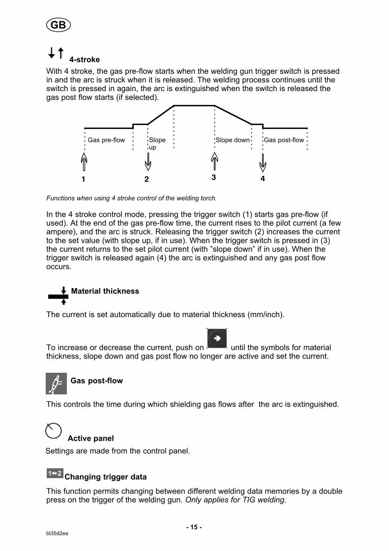
2-stroke
With 2-stroke gas pre-flow (if used) starts when the welding gun trigger switch ispressed. The welding process then starts. Releasing the trigger switch stops welding entirely and starts gas post-flow (if selected).
Gas pre-flow Slopeup
Slope down Gas post-flow
Functions when using 2 stroke control of the welding torch.
In the 2 stroke control mode, pressing the TIG torch trigger switch (1) starts gaspre-flow (if used) and strikes the arc. The current rises to the set value (as controlledby the slope up function, if in operation). Releasing the trigger switch (2) reduces thecurrent (or starts slope down if in operation) and extinguishes the arc. Gas post-flowfollows if it is in operation.
GB
- 15 -bt35d2ea
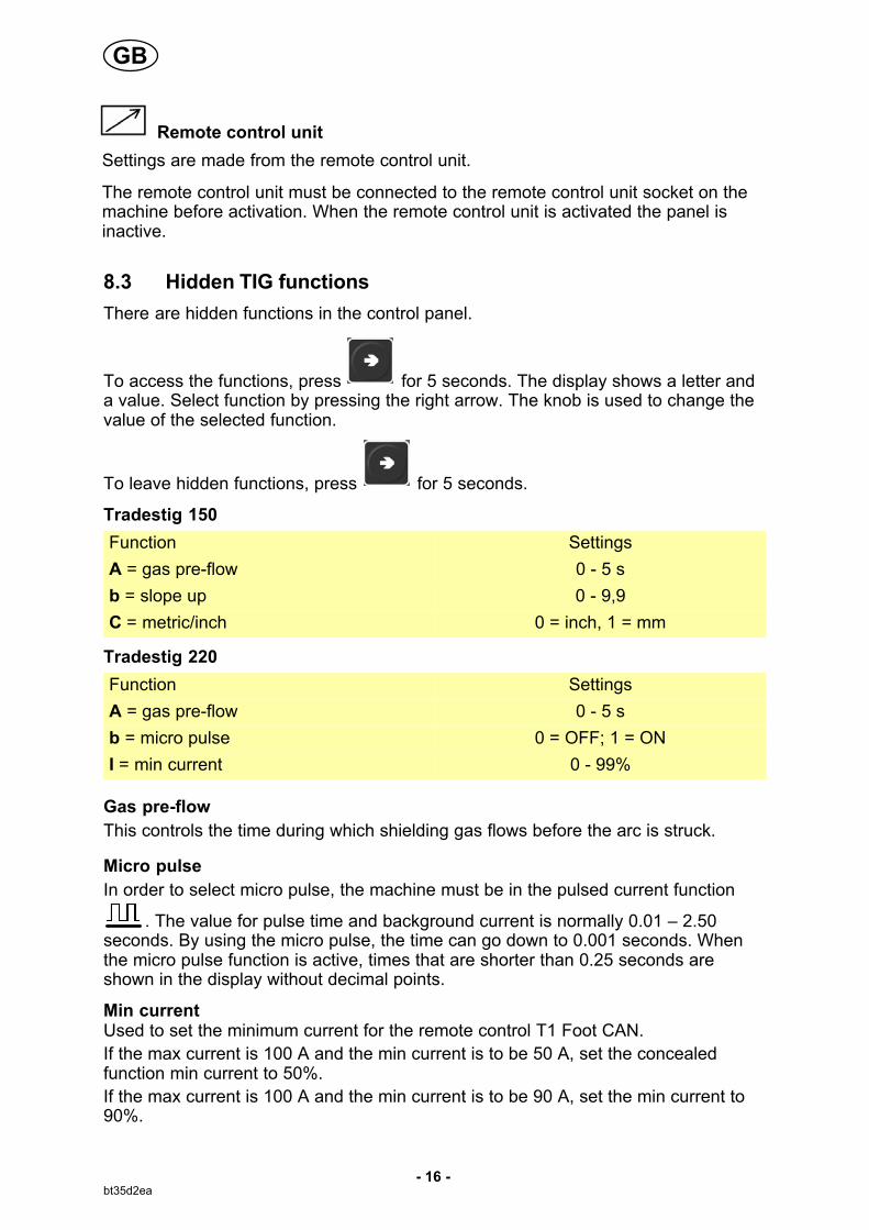
4-stroke
With 4 stroke, the gas pre-flow starts when the welding gun trigger switch is pressedin and the arc is struck when it is released. The welding process continues until theswitch is pressed in again, the arc is extinguished when the switch is released thegas post flow starts (if selected).
Gas pre-flow Slopeup
Slope down Gas post-flow
Functions when using 4 stroke control of the welding torch.
In the 4 stroke control mode, pressing the trigger switch (1) starts gas pre-flow (ifused). At the end of the gas pre-flow time, the current rises to the pilot current (a fewampere), and the arc is struck. Releasing the trigger switch (2) increases the currentto the set value (with slope up, if in use). When the trigger switch is pressed in (3)the current returns to the set pilot current (with ”slope down” if in use). When thetrigger switch is released again (4) the arc is extinguished and any gas post flowoccurs.
Material thickness
The current is set automatically due to material thickness (mm/inch).
To increase or decrease the current, push on until the symbols for materialthickness, slope down and gas post flow no longer are active and set the current.
Gas post-flow
This controls the time during which shielding gas flows after the arc is extinguished.
Active panel
Settings are made from the control panel.
Changing trigger data
This function permits changing between different welding data memories by a doublepress on the trigger of the welding gun. Only applies for TIG welding.
GB
- 16 -bt35d2ea
Remote control unit
Settings are made from the remote control unit.
The remote control unit must be connected to the remote control unit socket on themachine before activation. When the remote control unit is activated the panel isinactive.
8.3 Hidden TIG functions
There are hidden functions in the control panel.
To access the functions, press for 5 seconds. The display shows a letter anda value. Select function by pressing the right arrow. The knob is used to change thevalue of the selected function.
To leave hidden functions, press for 5 seconds.
Tradestig 150
Function Settings
A = gas pre-flow 0 - 5 s
b = slope up 0 - 9,9
C = metric/inch 0 = inch, 1 = mm
Tradestig 220
Function Settings
A = gas pre-flow 0 - 5 s
b = micro pulse 0 = OFF; 1 = ON
I = min current 0 - 99%
Gas pre-flow
This controls the time during which shielding gas flows before the arc is struck.
Micro pulse
In order to select micro pulse, the machine must be in the pulsed current function
. The value for pulse time and background current is normally 0.01 – 2.50seconds. By using the micro pulse, the time can go down to 0.001 seconds. Whenthe micro pulse function is active, times that are shorter than 0.25 seconds areshown in the display without decimal points.
Min currentUsed to set the minimum current for the remote control T1 Foot CAN.
If the max current is 100 A and the min current is to be 50 A, set the concealedfunction min current to 50%.
If the max current is 100 A and the min current is to be 90 A, set the min current to90%.
GB
- 17 -bt35d2ea
9 MMA WELDING
9.1 Settings
Function Setting range Tradestig 150 Tradestig 220
Current 16 - max. A 2) x x
Hotstart 1) 0 - 99 - x
Arc force 1) 0 - 99 - x
Drop welding 1) 0=OFF or 1=ON - x
Weld regulator ArcPlus� 1) 1=OFF or 0=ON - x
Active panel OFF or ON - x
Remote control unit OFF or ON - x
1) These functions are hiddenfunctions, see description point 9.3.2) The setting range is dependent on the power source used.
9.2 Symbol and Function explanations MMA
MMA welding
MMA welding may also be referred to as welding with coated electrodes. Striking thearc melts the electrode, and its coating forms protective slag.
Active panel
Settings are made from the control panel.
Remote control unit
Settings are made from the remote control unit.
The remote control unit must be connected to the remote control unit socket on themachine before activation. When the remote control unit is activated the panel isinactive.
GB
- 18 -bt35d2ea
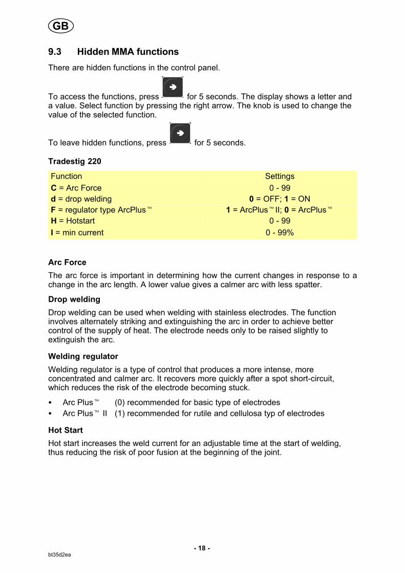
9.3 Hidden MMA functions
There are hidden functions in the control panel.
To access the functions, press for 5 seconds. The display shows a letter anda value. Select function by pressing the right arrow. The knob is used to change thevalue of the selected function.
To leave hidden functions, press for 5 seconds.
Tradestig 220
Function Settings
C = Arc Force 0 - 99
d = drop welding 0 = OFF; 1 = ON
F = regulator type ArcPlus� 1 = ArcPlus�II; 0 = ArcPlus�
H = Hotstart 0 - 99
I = min current 0 - 99%
Arc Force
The arc force is important in determining how the current changes in response to achange in the arc length. A lower value gives a calmer arc with less spatter.
Drop welding
Drop welding can be used when welding with stainless electrodes. The functioninvolves alternately striking and extinguishing the arc in order to achieve bettercontrol of the supply of heat. The electrode needs only to be raised slightly toextinguish the arc.
Welding regulator
Welding regulator is a type of control that produces a more intense, moreconcentrated and calmer arc. It recovers more quickly after a spot short-circuit,which reduces the risk of the electrode becoming stuck.
� Arc Plus� (0) recommended for basic type of electrodes
� Arc Plus� II (1) recommended for rutile and cellulosa typ of electrodes
Hot Start
Hot start increases the weld current for an adjustable time at the start of welding,thus reducing the risk of poor fusion at the beginning of the joint.
GB
- 19 -bt35d2ea
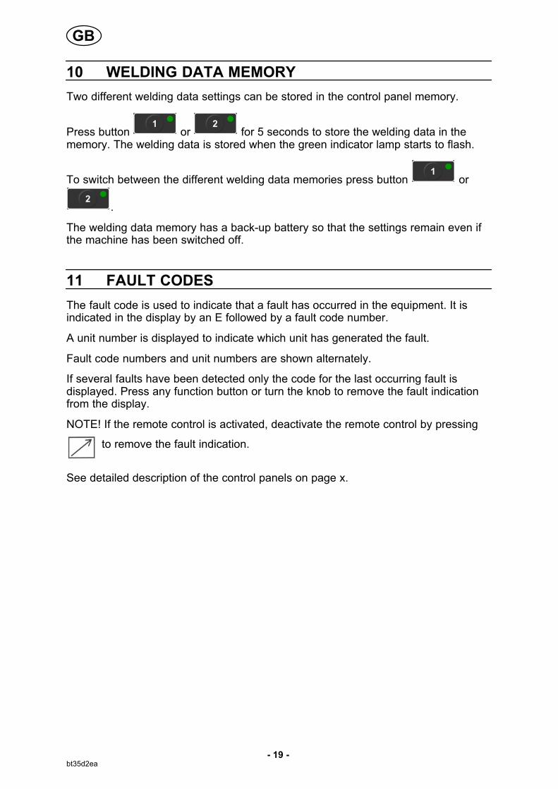
10 WELDING DATA MEMORY
Two different welding data settings can be stored in the control panel memory.
Press button or for 5 seconds to store the welding data in thememory. The welding data is stored when the green indicator lamp starts to flash.
To switch between the different welding data memories press button or
.
The welding data memory has a back-up battery so that the settings remain even ifthe machine has been switched off.
11 FAULT CODES
The fault code is used to indicate that a fault has occurred in the equipment. It isindicated in the display by an E followed by a fault code number.
A unit number is displayed to indicate which unit has generated the fault.
Fault code numbers and unit numbers are shown alternately.
If several faults have been detected only the code for the last occurring fault isdisplayed. Press any function button or turn the knob to remove the fault indicationfrom the display.
NOTE! If the remote control is activated, deactivate the remote control by pressing
to remove the fault indication.
See detailed description of the control panels on page x.
GB
- 20 -bt35d2ea
12 MAINTENANCE
Regular maintenance is important for safe, reliable operation.
Only those persons who have appropriate electrical knowledge (authorizedpersonnel) may remove the safety plates to connect or carry out service,maintenance or repair work on welding equipment.
CAUTION!
All guarantee undertakings from the supplier cease to apply if the customer himselfattempts any work in the product during the guarantee period in order to rectify any faults.
12.1 Inspection and cleaning
Power source
Check regularly that the welding power source is not clogged with dirt.
How often and which cleaning methods apply depend on: the welding process, arctimes, placement, and the surrounding environment. It is normally sufficient to blowdown the power source with dry compressed air (reduced pressure) once a year.
Clogged or blocked air inlets and outlets otherwise result in overheating.
Welding torch
The welding torch's wear parts should be cleaned and replaced at regular intervals inorder to achieve trouble-free welding.
13 FAULT-TRACING
Try these recommended checks and inspections before sending for an authorisedservice technician.
Type of fault Corrective action
No arc. � Check that the mains power supply switch is turned on.
� Check that the welding current supply and return cables arecorrectly connected.
� Check that the correct current value is set.
� Check the mains power supply.
The welding current isinterrupted during welding.
� Check to see whether the thermal cut-outs have tripped.
� Check the mains power supply fuses.
The thermal cut-out tripsfrequently.
� Make sure that you are not exceeding the rated data for thewelding power source (i.e. that the unit is not beingoverloaded).
� Make sure that the power source is clean.
Poor welding performance. � Check that the welding current supply and return cables arecorrectly connected.
� Check that the correct current value is set.
� Check that the correct electrodes are being used.
� Check the gas flow.
GB
- 21 -bt35d2ea
14 ORDERING SPARE PARTS
Repair and electrical work should be performed by an authorized serviceman.Use only original spare and wear parts.
TYPE is designed and tested in accordance with the international and European standards EN and EN . It is the obligation of the service unit which has carried out theservice or repair work to make sure that the product still conforms to the said standard.
15 DISMANTLING AND SCRAPPING
Welding equipment primarily consists of steel, plastic and non-ferrous metals, and mustbe handled according to local environmental regulations.Coolant must also be handled according to local environmental regulations.
Do not dispose of electrical equipment together with normal waste!
In observance of European Directive 2002/96/EC on Waste Electrical and ElectronicEquipment and its implementation in accordance with national law, electrical equipmentthat has reached the end of its life must be collected separately and returned to anenvironmentally compatible recycling facility. As the owner of the equipment, you shouldget information on approved collection systems from our local representative.
By applying this European Directive you will improve the environment and humanhealth!
GB
Edition 100217
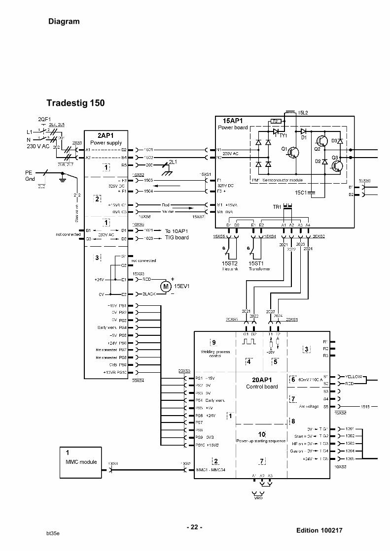
Diagram
- 22 -bt35e
Tradestig 150
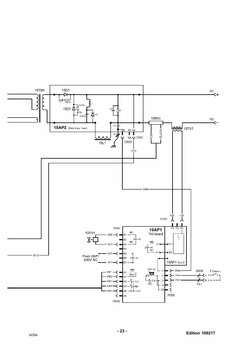
Edition 100217- 23 -
bt35e
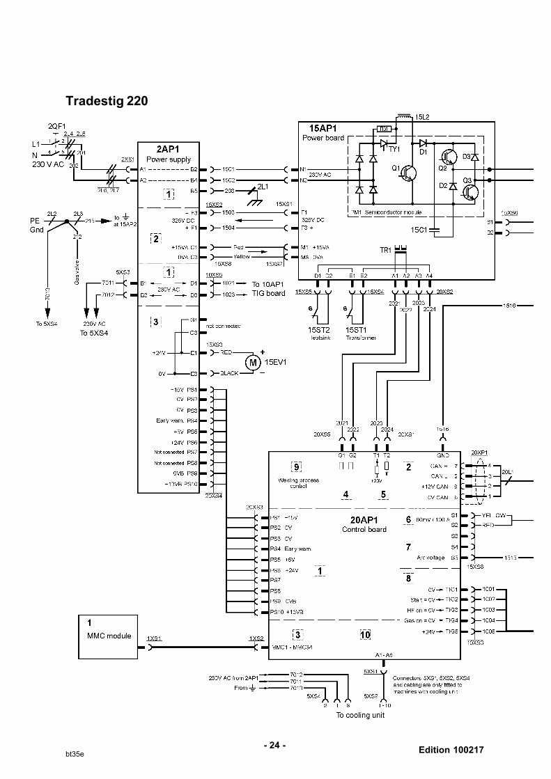
Edition 100217- 24 -
bt35e
Tradestig 220
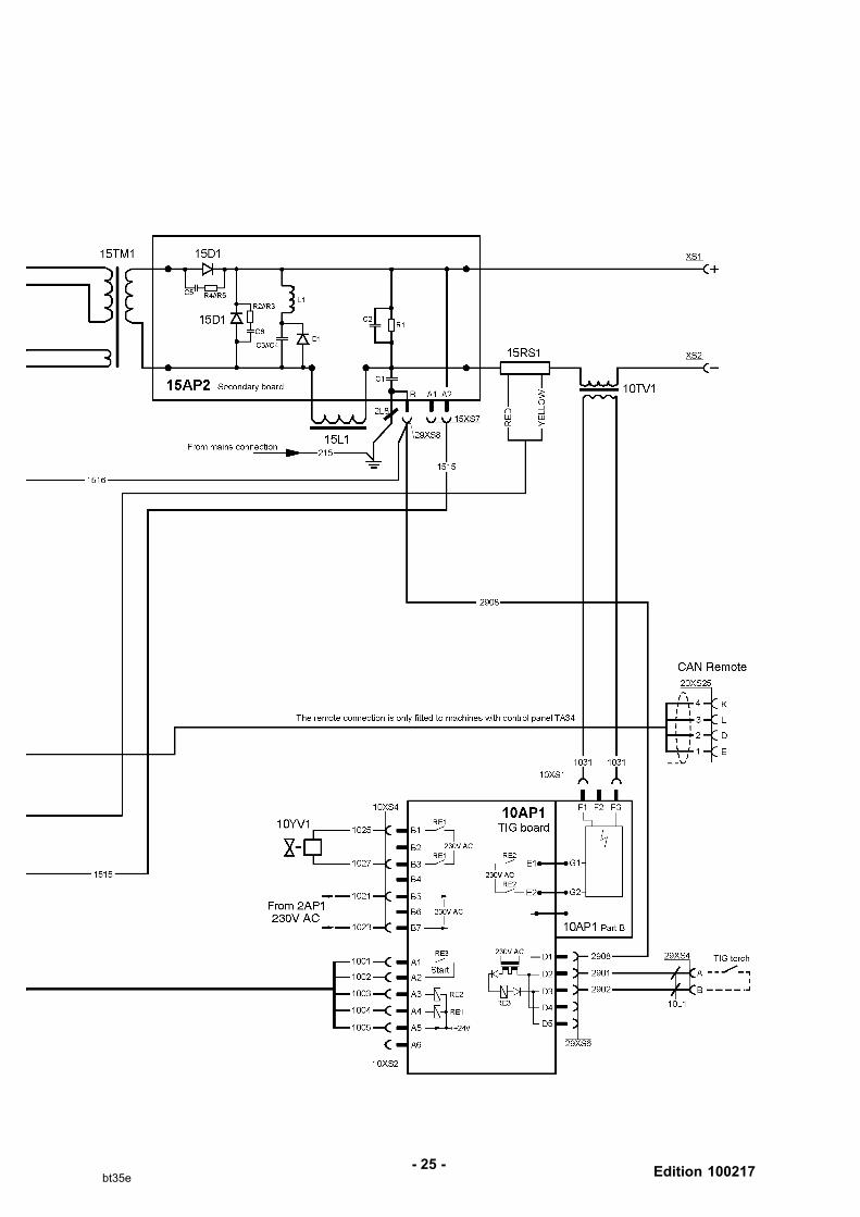
Edition 100217- 25 -
bt35e

- 26 -p
Tradestig 150, Tradestig 220
Edition 100217
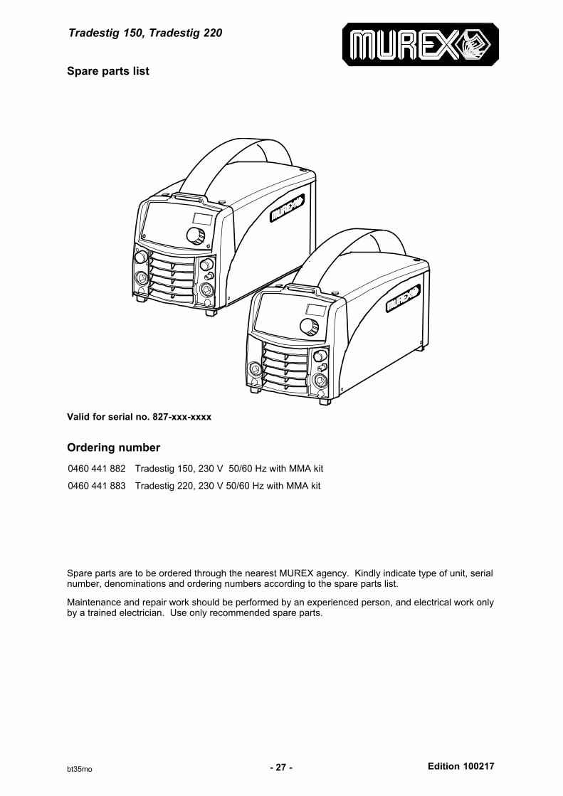
Spare parts list
- 27 -bt35mo
Valid for serial no. 827-xxx-xxxx
Ordering number
0460 441 882 Tradestig 150, 230 V 50/60 Hz with MMA kit
0460 441 883 Tradestig 220, 230 V 50/60 Hz with MMA kit
Spare parts are to be ordered through the nearest MUREX agency. Kindly indicate type of unit, serialnumber, denominations and ordering numbers according to the spare parts list.
Maintenance and repair work should be performed by an experienced person, and electrical work onlyby a trained electrician. Use only recommended spare parts.
Tradestig 150
Edition 100217- 28 -bt35maa1
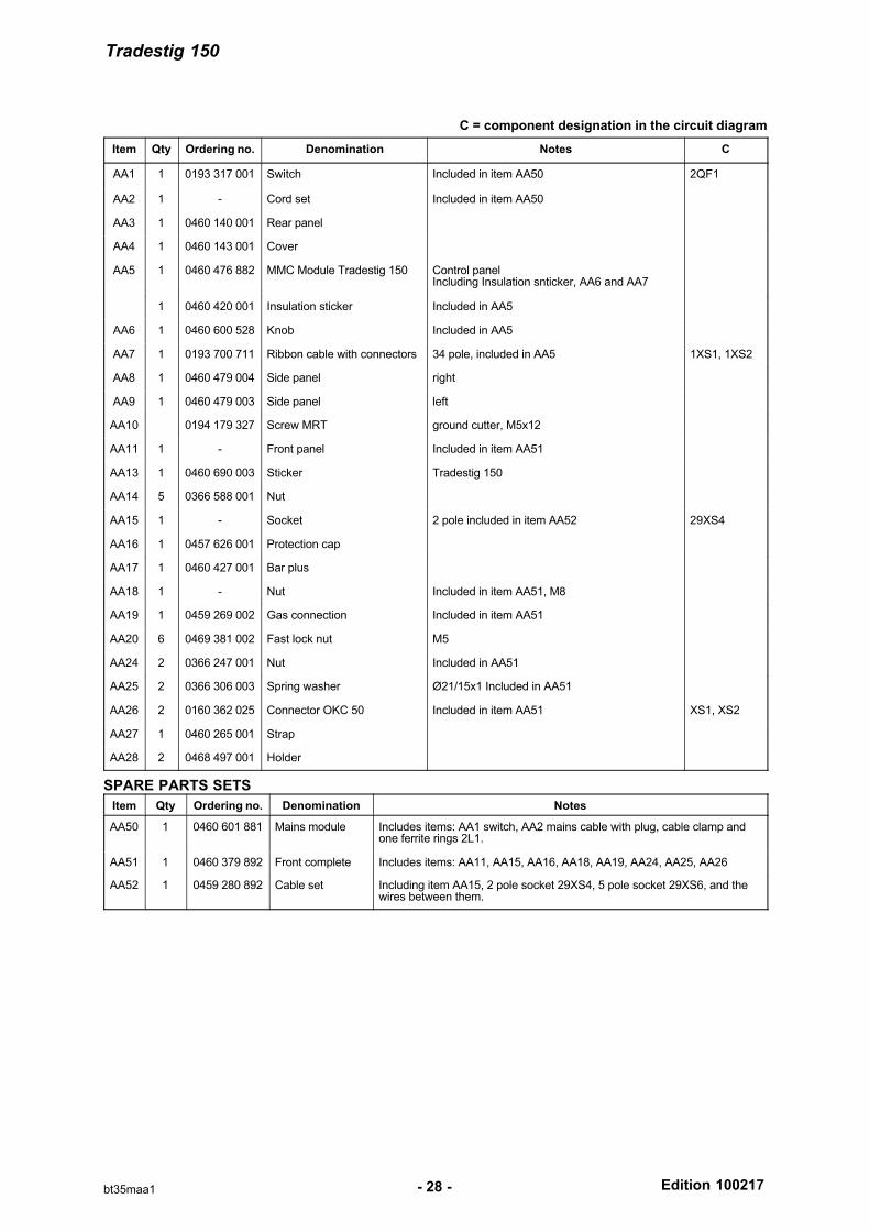
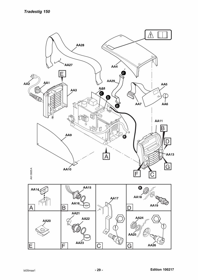
C = component designation in the circuit diagram
Item Qty Ordering no. Denomination Notes C
AA1 1 0193 317 001 Switch Included in item AA50 2QF1
AA2 1 - Cord set Included in item AA50
AA3 1 0460 140 001 Rear panel
AA4 1 0460 143 001 Cover
AA5 1 0460 476 882 MMC Module Tradestig 150 Control panelIncluding Insulation snticker, AA6 and AA7
1 0460 420 001 Insulation sticker Included in AA5
AA6 1 0460 600 528 Knob Included in AA5
AA7 1 0193 700 711 Ribbon cable with connectors 34 pole, included in AA5 1XS1, 1XS2
AA8 1 0460 479 004 Side panel right
AA9 1 0460 479 003 Side panel left
AA10 0194 179 327 Screw MRT ground cutter, M5x12
AA11 1 - Front panel Included in item AA51
AA13 1 0460 690 003 Sticker Tradestig 150
AA14 5 0366 588 001 Nut
AA15 1 - Socket 2 pole included in item AA52 29XS4
AA16 1 0457 626 001 Protection cap
AA17 1 0460 427 001 Bar plus
AA18 1 - Nut Included in item AA51, M8
AA19 1 0459 269 002 Gas connection Included in item AA51
AA20 6 0469 381 002 Fast lock nut M5
AA24 2 0366 247 001 Nut Included in AA51
AA25 2 0366 306 003 Spring washer Ø21/15x1 Included in AA51
AA26 2 0160 362 025 Connector OKC 50 Included in item AA51 XS1, XS2
AA27 1 0460 265 001 Strap
AA28 2 0468 497 001 Holder
SPARE PARTS SETS
Item Qty Ordering no. Denomination Notes
AA50 1 0460 601 881 Mains module Includes items: AA1 switch, AA2 mains cable with plug, cable clamp andone ferrite rings 2L1.
AA51 1 0460 379 892 Front complete Includes items: AA11, AA15, AA16, AA18, AA19, AA24, AA25, AA26
AA52 1 0459 280 892 Cable set Including item AA15, 2 pole socket 29XS4, 5 pole socket 29XS6, and thewires between them.
Tradestig 150
Edition 100217- 29 -bt35maa1
Tradestig 150
Edition 100217- 30 -bt35mab1
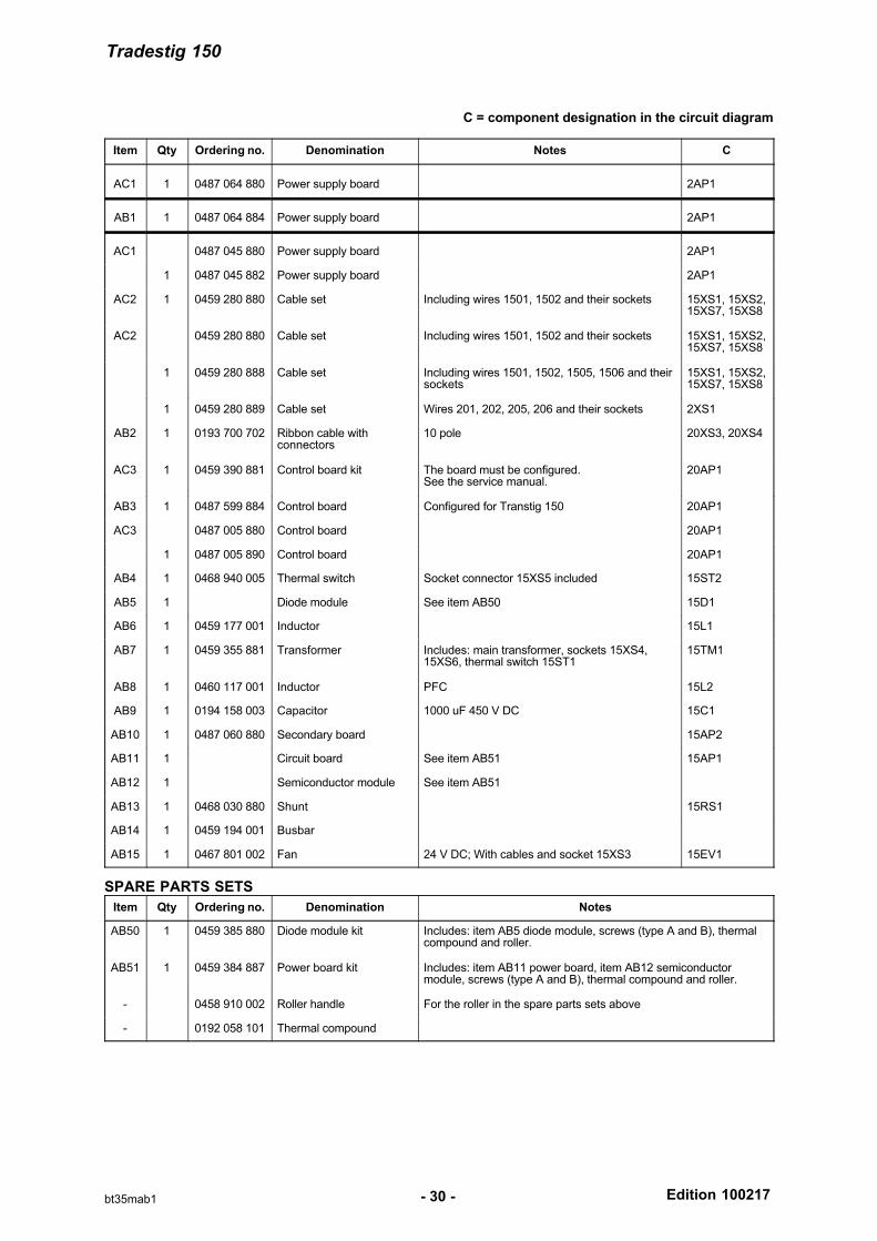
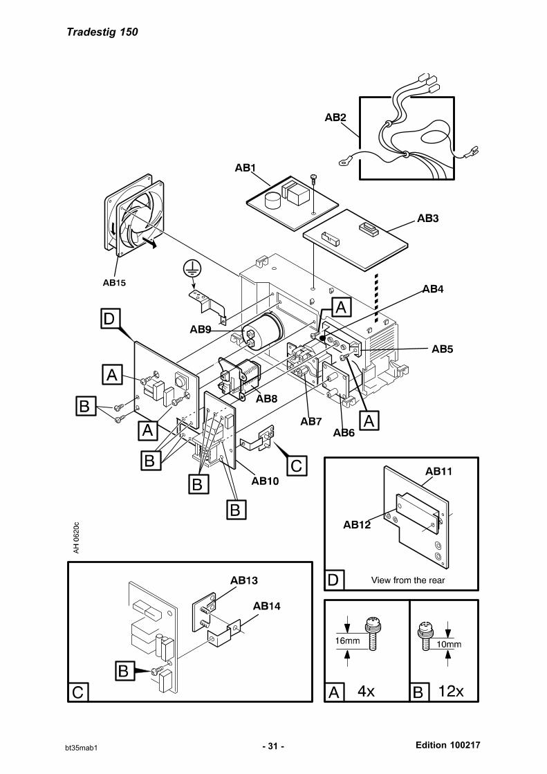
C = component designation in the circuit diagram
Item Qty Ordering no. Denomination Notes C
AC1 1 0487 064 880 Power supply board 2AP1
AB1 1 0487 064 884 Power supply board 2AP1
AC1 0487 045 880 Power supply board 2AP1
1 0487 045 882 Power supply board 2AP1
AC2 1 0459 280 880 Cable set Including wires 1501, 1502 and their sockets 15XS1, 15XS2,15XS7, 15XS8
AC2 0459 280 880 Cable set Including wires 1501, 1502 and their sockets 15XS1, 15XS2,15XS7, 15XS8
1 0459 280 888 Cable set Including wires 1501, 1502, 1505, 1506 and theirsockets
15XS1, 15XS2,15XS7, 15XS8
1 0459 280 889 Cable set Wires 201, 202, 205, 206 and their sockets 2XS1
AB2 1 0193 700 702 Ribbon cable with connectors
10 pole 20XS3, 20XS4
AC3 1 0459 390 881 Control board kit The board must be configured. See the service manual.
20AP1
AB3 1 0487 599 884 Control board Configured for Transtig 150 20AP1
AC3 0487 005 880 Control board 20AP1
1 0487 005 890 Control board 20AP1
AB4 1 0468 940 005 Thermal switch Socket connector 15XS5 included 15ST2
AB5 1 Diode module See item AB50 15D1
AB6 1 0459 177 001 Inductor 15L1
AB7 1 0459 355 881 Transformer Includes: main transformer, sockets 15XS4,15XS6, thermal switch 15ST1
15TM1
AB8 1 0460 117 001 Inductor PFC 15L2
AB9 1 0194 158 003 Capacitor 1000 uF 450 V DC 15C1
AB10 1 0487 060 880 Secondary board 15AP2
AB11 1 Circuit board See item AB51 15AP1
AB12 1 Semiconductor module See item AB51
AB13 1 0468 030 880 Shunt 15RS1
AB14 1 0459 194 001 Busbar
AB15 1 0467 801 002 Fan 24 V DC; With cables and socket 15XS3 15EV1
SPARE PARTS SETS
Item Qty Ordering no. Denomination Notes
AB50 1 0459 385 880 Diode module kit Includes: item AB5 diode module, screws (type A and B), thermalcompound and roller.
AB51 1 0459 384 887 Power board kit Includes: item AB11 power board, item AB12 semiconductormodule, screws (type A and B), thermal compound and roller.
- 0458 910 002 Roller handle For the roller in the spare parts sets above
- 0192 058 101 Thermal compound
Tradestig 150
Edition 100217- 31 -bt35mab1
Tradestig 150, Tradestig 220
Edition 100217- 32 -bt35mac1
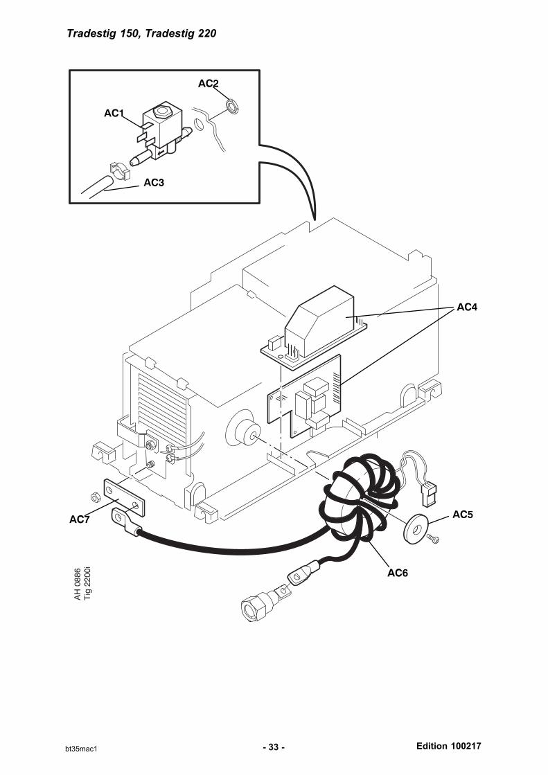
C = component designation in the circuit diagram
Item Qty Ordering no. Denomination Notes C
AC1 1 0193 054 005 Solenoid valve 230 V AC 10YV1
AC2 1 Nut ML6M MF10x1
AC3 1 0456 496 001 Hose D = 9/5 mm, L = 0.57 metre reinforced PVC
AC4 1 0487 028 880 Circuit board TIG 10AP1
AC5 1 0459 258 001 Coil bracket
AC6 1 0460 135 001 HF coil 10TV1, 10XS1
AC7 1 0460 427 002 Bar Negative
Tradestig 150, Tradestig 220
Edition 100217- 33 -bt35mac1
Tradestig 220
Edition 100217- 34 -bt35mba1
C = component designation in the circuit diagram
Item Qty Ordering no. Denomination Notes C
AA1 1 0193 317 001 Switch Included in item AA50 2QF1
AA2 1 - Cord set Included in item AA50
AA3 1 0460 140 001 Rear panel
AA4 1 0460 143 001 Cover
AA5 1 0460 476 883 MMC Module Transtig 220 Control panelIncluding Insulation snticker, AA6 and AA7
1 0460 420 001 Insulation sticker Included in AA5
AA6 1 0460 600 528 Knob Included in AA5
AA7 1 0193 700 711 Ribbon cable with connectors 34 pole, included in AA5 1XS1, 1XS2
AA8 1 0460 479 004 Side panel right
AA9 1 0460 479 003 Side panel left
AA10 0194 179 327 Screw MRT ground cutter, M5x12
AA11 1 - Front panel Included in item AA51
AA13 1 0460 690 004 Sticker Tradestig 220
AA14 5 0366 588 001 Nut
AA15 1 - Socket 2 pole Included in item AA51 and AA52 29XS4
AA16 1 0457 626 001 Protection cap Included in item AA51
AA17 1 0460 427 001 Bar plus
AA18 1 - Nut Included in item AA51, M8
AA19 1 0459 269 002 Gas connection Included in item AA51
AA20 6 0469 381 002 Fast lock nut M5
AA21 1 0194 227 003 Clamp Only TA34 Included in item AA51
AA22 1 0458 681 897 Cable with connectors Only TA34 Included in item AA51 20XS25,20XP1
AA23 1 0366 285 001 Protection cap Only TA34 Included in item AA51
AA24 2 0366 247 001 Nut Included in item AA51
AA25 2 0366 306 003 Spring washer Ø21/15x1 Included in item AA51
AA26 2 0160 362 025 Connector OKC 50 Included in item AA51 XS1, XS2
AA27 1 0460 265 001 Strap
AA28 2 0468 497 001 Holder
Tradestig 220
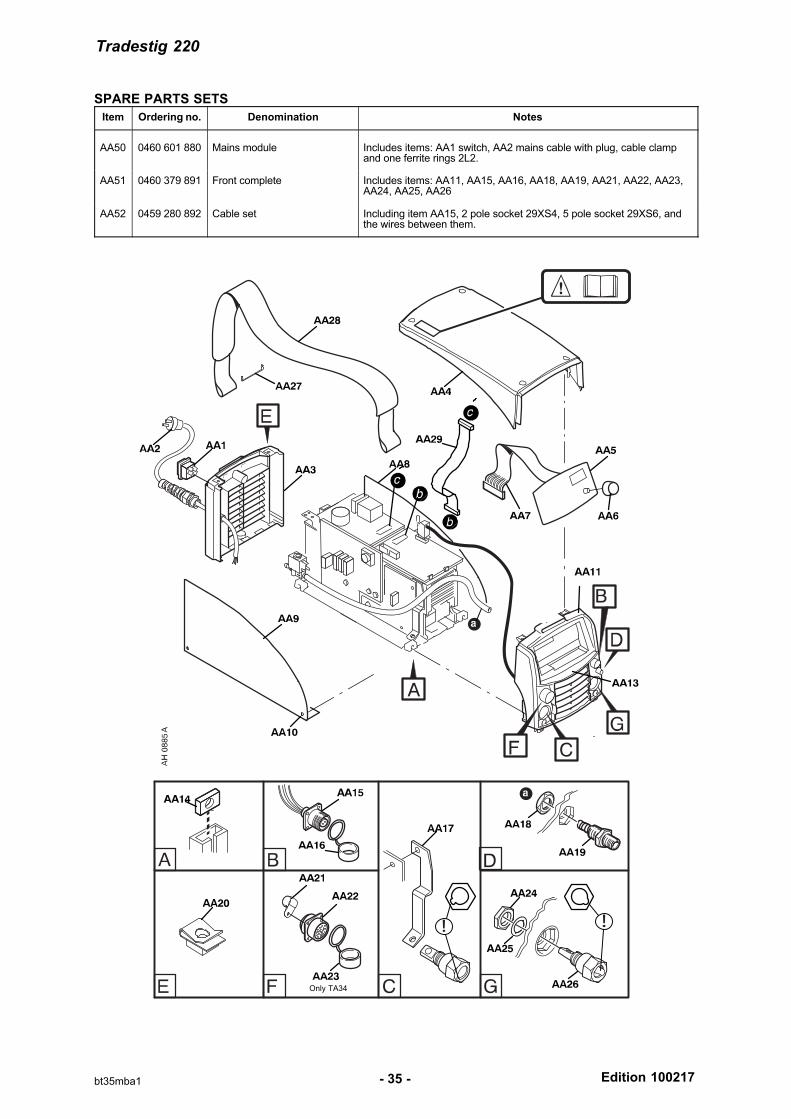
Edition 100217- 35 -bt35mba1
SPARE PARTS SETS
Item Ordering no. Denomination Notes
AA50 0460 601 880 Mains module Includes items: AA1 switch, AA2 mains cable with plug, cable clampand one ferrite rings 2L2.
AA51 0460 379 891 Front complete Includes items: AA11, AA15, AA16, AA18, AA19, AA21, AA22, AA23,AA24, AA25, AA26
AA52 0459 280 892 Cable set Including item AA15, 2 pole socket 29XS4, 5 pole socket 29XS6, andthe wires between them.
Only TA34
Tradestig 220
Edition 100217- 36 -bt35mbb1
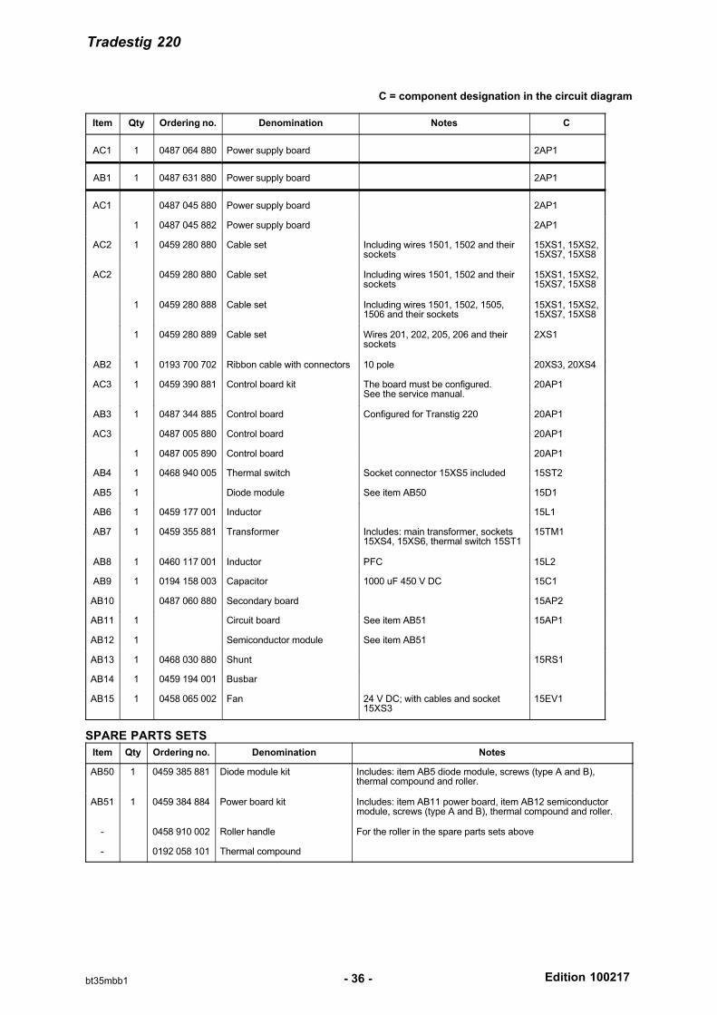
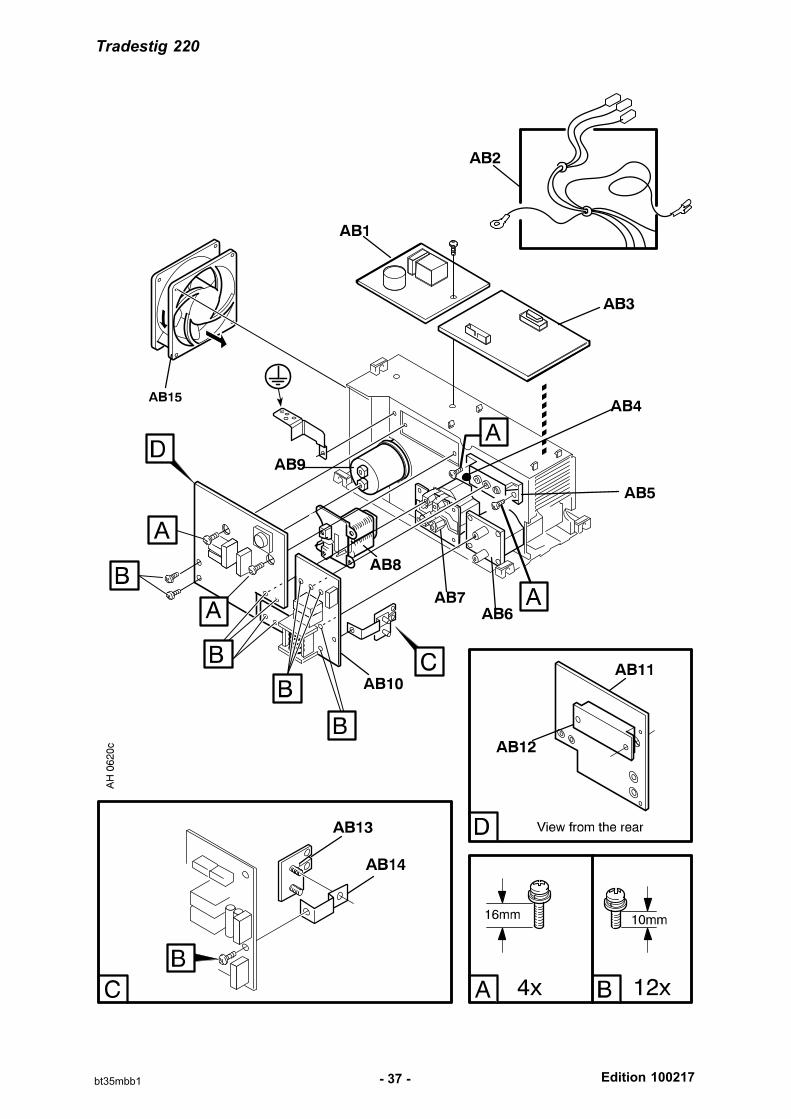
C = component designation in the circuit diagram
Item Qty Ordering no. Denomination Notes C
AC1 1 0487 064 880 Power supply board 2AP1
AB1 1 0487 631 880 Power supply board 2AP1
AC1 0487 045 880 Power supply board 2AP1
1 0487 045 882 Power supply board 2AP1
AC2 1 0459 280 880 Cable set Including wires 1501, 1502 and theirsockets
15XS1, 15XS2,15XS7, 15XS8
AC2 0459 280 880 Cable set Including wires 1501, 1502 and theirsockets
15XS1, 15XS2,15XS7, 15XS8
1 0459 280 888 Cable set Including wires 1501, 1502, 1505,1506 and their sockets
15XS1, 15XS2,15XS7, 15XS8
1 0459 280 889 Cable set Wires 201, 202, 205, 206 and theirsockets
2XS1
AB2 1 0193 700 702 Ribbon cable with connectors 10 pole 20XS3, 20XS4
AC3 1 0459 390 881 Control board kit The board must be configured. See the service manual.
20AP1
AB3 1 0487 344 885 Control board Configured for Transtig 220 20AP1
AC3 0487 005 880 Control board 20AP1
1 0487 005 890 Control board 20AP1
AB4 1 0468 940 005 Thermal switch Socket connector 15XS5 included 15ST2
AB5 1 Diode module See item AB50 15D1
AB6 1 0459 177 001 Inductor 15L1
AB7 1 0459 355 881 Transformer Includes: main transformer, sockets15XS4, 15XS6, thermal switch 15ST1
15TM1
AB8 1 0460 117 001 Inductor PFC 15L2
AB9 1 0194 158 003 Capacitor 1000 uF 450 V DC 15C1
AB10 0487 060 880 Secondary board 15AP2
AB11 1 Circuit board See item AB51 15AP1
AB12 1 Semiconductor module See item AB51
AB13 1 0468 030 880 Shunt 15RS1
AB14 1 0459 194 001 Busbar
AB15 1 0458 065 002 Fan 24 V DC; with cables and socket15XS3
15EV1
SPARE PARTS SETS
Item Qty Ordering no. Denomination Notes
AB50 1 0459 385 881 Diode module kit Includes: item AB5 diode module, screws (type A and B),thermal compound and roller.
AB51 1 0459 384 884 Power board kit Includes: item AB11 power board, item AB12 semiconductormodule, screws (type A and B), thermal compound and roller.
- 0458 910 002 Roller handle For the roller in the spare parts sets above
- 0192 058 101 Thermal compound
Tradestig 220
Edition 100217- 37 -bt35mbb1
Edition 100217
Tradestig 150, Tradestig 220
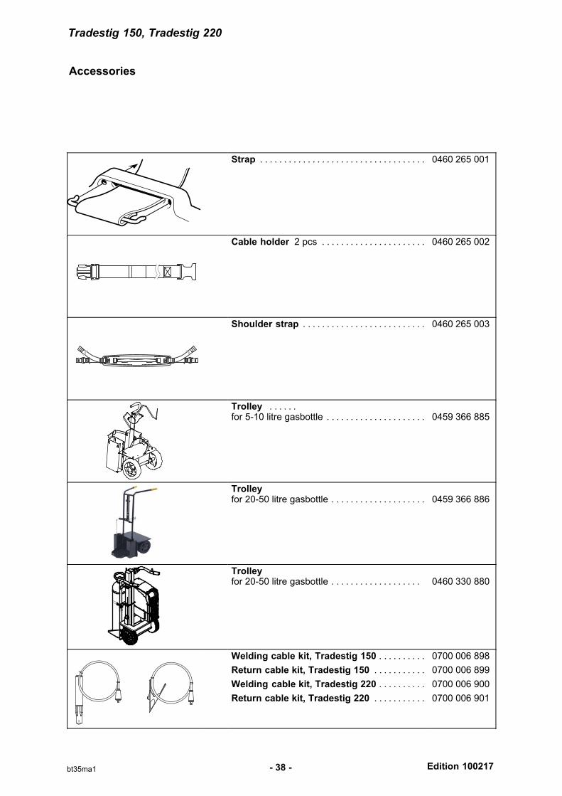
Accessories
- 38 -bt35ma1
Strap . . . . . . . . . . . . . . . . . . . . . . . . . . . . . . . . . . . 0460 265 001
Cable holder 2 pcs . . . . . . . . . . . . . . . . . . . . . . 0460 265 002
Shoulder strap . . . . . . . . . . . . . . . . . . . . . . . . . . 0460 265 003
Trolley . . . . . . for 5-10 litre gasbottle . . . . . . . . . . . . . . . . . . . . . 0459 366 885
Trolleyfor 20-50 litre gasbottle . . . . . . . . . . . . . . . . . . . . 0459 366 886
Trolleyfor 20-50 litre gasbottle . . . . . . . . . . . . . . . . . . . 0460 330 880
Welding cable kit, Tradestig 150 . . . . . . . . . .
Return cable kit, Tradestig 150 . . . . . . . . . . .
Welding cable kit, Tradestig 220 . . . . . . . . . .
Return cable kit, Tradestig 220 . . . . . . . . . . .
0700 006 898
0700 006 899
0700 006 900
0700 006 901
Edition 100217
Tradestig 220
- 39 -bt35ma2
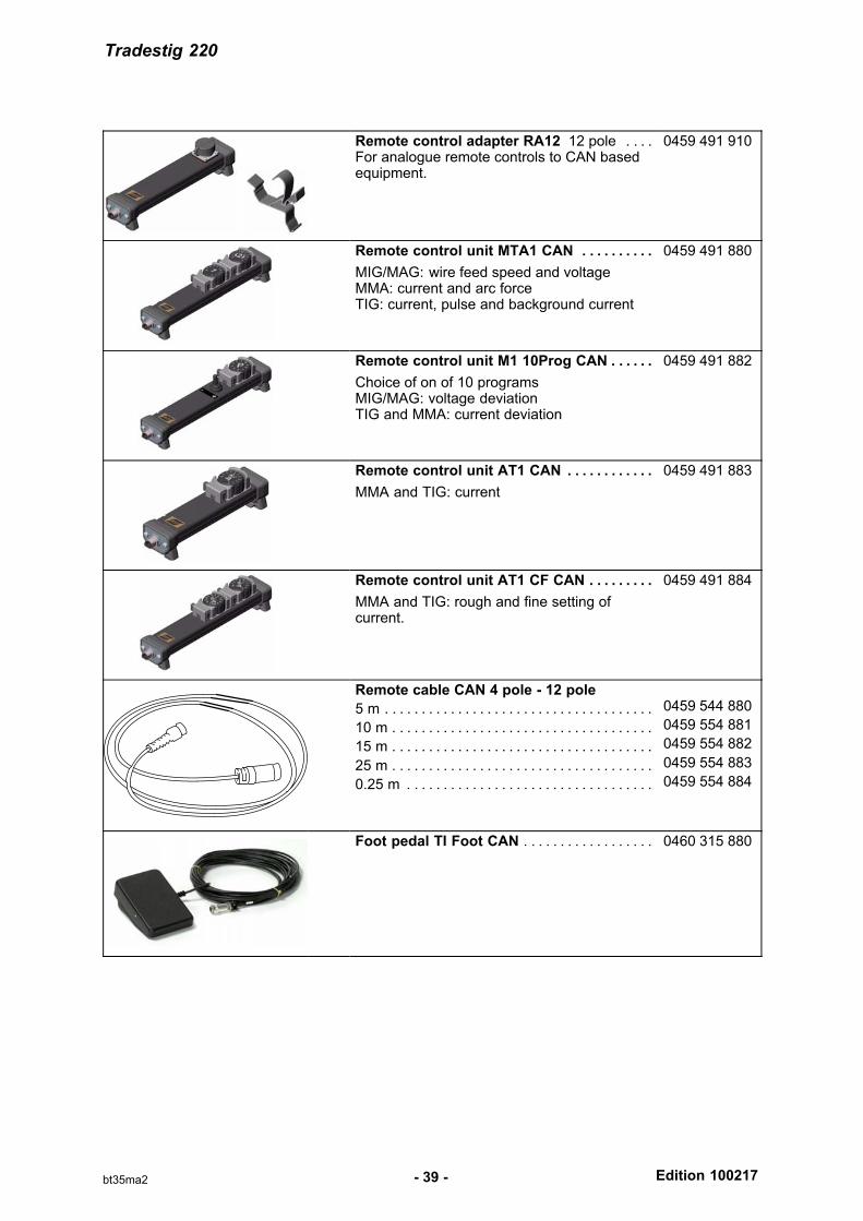
Remote control adapter RA12 12 pole . . . . For analogue remote controls to CAN basedequipment.
0459 491 910
Remote control unit MTA1 CAN . . . . . . . . . .
MIG/MAG: wire feed speed and voltageMMA: current and arc forceTIG: current, pulse and background current
0459 491 880
Remote control unit M1 10Prog CAN . . . . . .
Choice of on of 10 programsMIG/MAG: voltage deviationTIG and MMA: current deviation
0459 491 882
Remote control unit AT1 CAN . . . . . . . . . . . .
MMA and TIG: current
0459 491 883
Remote control unit AT1 CF CAN . . . . . . . . .
MMA and TIG: rough and fine setting ofcurrent.
0459 491 884
Remote cable CAN 4 pole - 12 pole
5 m . . . . . . . . . . . . . . . . . . . . . . . . . . . . . . . . . . . . .
10 m . . . . . . . . . . . . . . . . . . . . . . . . . . . . . . . . . . . .
15 m . . . . . . . . . . . . . . . . . . . . . . . . . . . . . . . . . . . .
25 m . . . . . . . . . . . . . . . . . . . . . . . . . . . . . . . . . . . .
0.25 m . . . . . . . . . . . . . . . . . . . . . . . . . . . . . . . . . .
0459 544 880
0459 554 881
0459 554 882
0459 554 883
0459 554 884
Foot pedal TI Foot CAN . . . . . . . . . . . . . . . . . . 0460 315 880

Murex Welding Products LtdHanover HouseQueensgateBritannia RoadWaltham CrossHertfordshire EN8 7TFEngland
Please ensure that thisOperating Manual is
available to the user ofthe equipment.