Embed Size (px)
Citation preview

Mainboard User’s Manual
This publication, including all photographs, illustrations andsoftware, is protected under international copyright laws, with allrights reserved. Neither this manual, nor any of the materialcontained herein, may be reproduced without the express writtenconsent of the manufacturer.The information in this document is subject to change withoutnotice. The manufacturer makes no representations or warrantieswith respect to the contents hereof and specifically disclaims anyimplied warranties of merchantability or fitness for any particularpurpose. Further, the manufacturer reserves the right to revise thispublication and to make changes from time to time in the contenthereof without obligation of the manufacturer to notify any personof such revision or changes.
TrademarksIBM, VGA, and PS/2 are registered trademarks of InternationalBusiness Machines.AMD and Athlon are registered trademarks of Advanced MicroDevices Inc.Intel, Pentium, Pentium-II, and MMX are registered trademarks ofIntel Corporation.Microsoft, MS-DOS and Windows 95/98/NT are registeredtrademarks of Microsoft Corporation.Sound Blaster is a trademark of Creative Technology Ltd.PC-cillin and ChipAwayVirus are trademarks of Trend Micro Inc.Award is a trademark of Award Software Inc.A3D is a registered trademark of Aureal Inc.MediaRing Talk is a registered trademark of MediaRing Inc.3Deep is a registered trademark of E-Color Inc.Other names used in this publication may be trademarks and areacknowledged.
Copyright © 2000All Rights Reserved
M810LMR, V1.6S73X/December 2000

Mainboard User’s Manual
II
Notice for AGP4X Slot:This mainboard provides an optional AGP4x slot. We recommendthe user should use one of the AGP VGA cards that we have tested.We will test more AGP VGA cards in the future. Users may getthis information from our World Wide Web atwww.pcchips.com.tw.
Model Chipset Memory Manufacture3D BLASTER GeForce 32M Creative CT6940ATI PERMEDIA 2 8M WinFast 3D L2300GeForce 256 32M ASUS V6600GeForce 2 MX 32M ASUS AGP-V7100GeForce 2 GTS DDR 32M ASUS AGP-7700DGeForce 2 GTS DDR 32M ELSA GLADIACGeForce 2 GTS 32M WinFastGeForce 2 MX 32M WinFastMatrox Productiva G100 8M MatroxMatrox Millennium G200 8M TAGRAMNVIDIA GeForce 256 DDR 32M ASUS V6800NVIDIA GeForce 256 32M Creative CT6970NVIDIA RIVA TNT2 Vanta 32M Top solutionRIVA TNT2 M64 16M PixelViewRIVA TNT 16M WinFast 3D S320RIVA TNT2 32M ASUS AGP-V3800RIVA TNT2 32M Creative CT6810

Mainboard User’s Manual
III
Table of Contents
Chapter 1: Introduction....................................................................1Key Features............................................................................2Package Contents.....................................................................5Static Electricity Precautions...................................................6Pre-Installation Inspection.......................................................6
Chapter 2: Mainboard Installation...................................................7Mainboard Components ..........................................................8I/O Ports...................................................................................9Install A CPU ..........................................................................9Install Memory ......................................................................11Setting Jumper Switches........................................................12Install the Mainboard.............................................................13Optional Extension Brackets .................................................14Install Other Devices .............................................................15Expansion Slots .....................................................................17
Chapter 3: BIOS Setup Utility.......................................................19Introduction ...........................................................................19Running the Setup Utility ......................................................20Standard CMOS Setup Page..................................................21Advanced Setup Page ............................................................22Power Management Setup Page ............................................23PCI / Plug and Play Setup Page.............................................25Load Optimal Settings ...........................................................25Load Best Performance Settings............................................26Features Setup Page...............................................................26CPU PnP Setup Page .............................................................28Hardware Monitor Page.........................................................29Change Password...................................................................29Exit ........................................................................................30
Chapter 4: Software & Applications .............................................31Introduction ...........................................................................31Installing Support Software ...................................................31Auto-installing under Windows 98........................................33

Mainboard User’s Manual
IV
Appendix A: Corel WordPerfect Suite 8 .................................A1Welcome to Corel WordPerfect Suite 8 ..............................A2Installing Corel WordPerfect Suite 8 ...................................A6Learning how to use Corel WordPerfect Suite 8 .................A9Support and Services .........................................................A13
Appendix B: Gamut2000 ...........................................................B11. GAMUT2000 Family ......................................................B2 1.1 LifeAmp - Versatile Audio Playback System ............B2 1.2 AudioPort - Audio Transportation System ................B42. Installation .......................................................................B5 2.1 Before Beginning: System Requirements ..................B5 2.2 Uninstalling the Previous of GAMUT2000................B53. Main Console ...................................................................B7 3.1 Introduction ...............................................................B7 3.2 Function and Operation .............................................B7 3.3 Main Menu ................................................................B9

1: Introduction
1
Chapter 1Introduction
This mainboard has a Socket-462 processor socket for an AMDK7 type CPUs. You can install any one of these processors on themainboard.
The mainboard supports Socket-462 processor front-side busspeeds of 200MHz.
This mainboard uses the T-Bird chipset which integrates a 128-bitAGP Graphics Accelerator, and provides a optional 4X AGP slotfor highly graphics display, CPU Plug & Play through firmware,Ultra DMA 33/66/100 function. The mainboard has a built-inAC97 Codec, provides an AMR (Audio Modem Riser) slot tosupport Audio and Modem application, and has a built-in10BaseT/100BaseTX Network Interface. In addition, themainboard has an extended set of ATX I/O Ports including PS/2keyboard and mouse ports, two USB ports, an RJ-45 LAN port, aparallel port, one serial port, and one VGA port. Two extra USBports can be added using the Extended USB Module that connectsto the mainboard.
This mainboard has all the features you need to develop a powerfulmultimedia workstation that is network ready. The board is MicroATX size and has power connectors for an ATX power supply.
Mainboard User’s Manual
2
Key FeaturesThe key features of this mainboard include:
Socket-462 Processor Support♦ Supports AMD Athlon/Duron processors♦ Supports 200 MHz Front-Side Bus
Processors are automatically configured using firmware and asynchronous Host/DRAM Clock Scheme.
Memory Support♦ Two DIMM slots for 168-pin SDRAM memory modules♦ Support for 100/133 MHz memory bus♦ Maximum installed memory is 2 x 512MB = 1GB
Expansion Slots♦ One AMR slot for a special audio/modem riser card♦ One optional AGP4X slot for AGP 2.0-compliant interface♦ Two 32-bit PCI slots for PCI 2.2-compliant bus interface.
Onboard IDE channels♦ Primary and Secondary PCI IDE channels♦ Support for PIO (programmable input/output) modes♦ Support for Multiword DMA modes♦ Support for Bus Mastering and Ultra DMA 33/66/100
modes
Power Supply and Power Management♦ ATX power supply connector♦ ACPI and previous PMU support, suspend switch,
keyboard power on/off♦ Supports Wake on Modem, Wake on LAN and Wake on
Alarm

1: Introduction
3
Built-in Graphics System♦ Onboard 128-bit 2D/3D 100MHz Host interface AGP
Graphics Accelerator Complies with AGP V2.0♦ Shared memory architecture allows a maximum of 64 MB
main memory to act as frame buffer♦ Supports high resolutions up to 1920x1440 Hi-colors, up to
2048x2048 Texture size and Virtual screen up to4096x4096
♦ Supports hardware DVD Accelerator
AC97 Codec♦ Compliant PC97 2.1 specification♦ Supports 18-bit ADC (Analog Digital Converter) and DAC
(Digital Analog Converter) as well as 18-bit stereo full-duplex codec
Onboard I/O Ports♦ Provides PC99 Color Connectors for easy peripheral device
connections♦ Floppy disk drive connector with 1Mb/s transfer rate♦ One serial port with 16550-compatible fast UART♦ One parallel port with ECP and EPP support♦ Two USB ports and optional two USB ports module♦ Two PS/2 ports for keyboard and mouse♦ One infrared port connector for optional module
Hardware Monitoring♦ Built-in hardware monitoring for CPU & System
temperatures, fan speeds and mainboard voltages
Built-in Ethernet LAN♦ Built-in 10BaseT/100BaseTX Ethernet LAN♦ LAN controller integrates Fast Ethernet MAC and PHY
compliant with IEEE802.3u 100BASE-TX, 10BASE-T andANSI X3.263 TP-PMD standards
♦ Compliant with ACPI 1.0 and the Network Device ClassPower Management 1.0

Mainboard User’s Manual
4
♦ High Performance provided by 100Mbps clock generatorand data recovery circuit for 100Mbps receiver
Onboard Flash ROM♦ Automatic CPU and board configuration♦ Supports Plug and Play configuration of peripheral devices
and expansion cards♦ Built-in virus protection using Trend’s ChipAwayVirus
provides boot process virus protection.
Bundled Software♦ PC-Cillin provides automatic virus protection under
Windows 95/98♦ MediaRing Talk provides PC to PC or PC to Phone
internet phone communication♦ Gamut2000 provides professional audio features included
MP3 encoding/playback♦ 3Deep delivers the precise imagery and displays accurate
color in your monitor♦ WinDVD is a DVD playback application (optional)♦ Corel WordPerfect Suite 8 is a Microsoft Windows®
office application suite (optional)
Dimensions♦ Micro ATX form factor (24.4cm x 24.4cm)

1: Introduction
5
Package ContentsYour mainboard package ships with the following items:
The mainboard This User’s Guide 1 UDMA/33 IDE cable 1 Floppy disk drive cable Support software on CD-ROM disk
Optional AccessoriesYou can purchase the following optional accessories for thismainboard.
Extended USB module AMR V.90 56K Fax/Modem card UDMA/66 IDE cable

Mainboard User’s Manual
6
Static Electricity PrecautionsComponents on this mainboard can be damaged by staticelectricity. Take the following precautions when unpacking themainboard and installing it in a system.1. Keep the mainboard and other components in their original
static-proof packaging until you are ready to install them.2. During installation, wear a grounded wrist strap if possible. If
you don’t have a wrist strap, discharge static electricity bytouching the bare metal of the system chassis.
3. Handle the mainboard carefully by the edges. Avoid touchingthe components unless it is absolutely necessary. Duringinstallation put the mainboard on top of the static-protectionpackaging it came in with the component side facing up.
Pre-Installation Inspection1. Inspect the mainboard for damage to the components and
connectors on the board.2. If you suspect that the mainboard has been damaged, do not
connect power to the system. Contact your mainboard vendorand report the damage.

2: Mainboard Installation
7
Chapter 2Mainboard Installation
To install this mainboard in a system, follow the procedures in thischapter:
Identify the mainboard components Install a CPU Install one or more system memory modules Verify that any jumpers or switches are set correctly Install the mainboard in a system chassis (case) Connect any extension brackets or cables to the mainboard
connector headers Install any other devices and make the appropriate connections
to the mainboard connector headers.
Note:1. Before installing this mainboard, make sure jumper JP4 set to
Normal setting. See this chapter for information on locatingJP4 and the setting options.
2. Never connect power to the system during installation. Doingso may damage the mainboard.

Mainboard User’s Manual
8
Mainboard ComponentsUse the diagram below to identify the major components on themainboard.
Note: Any jumper on your mainboard that do not appear inthe illustration above is for testing only.
CPU/

2: Mainboard Installation
9
I/O PortsThe illustration below shows a side view of the built-in I/O portson the mainboard.
PS/2 Mouse
PS/2 Keyboard
Parallel PortGame/MIDI Port
Serial Port COM1/3USB PortsMicrophone Jack Line-Out Jack
VGA Port
Line-In Jack
LAN Port
Install A CPUThis mainboard has a Socket-462 CPU socket for AMD K7processors.
To ensure reliability, ensure that your processor has aheatsink/cooling fan assembly.
Do not try to install a Socket-370/Socket-7 processor in the Socket-462. A Socket-370/Socket-7 processor such as the PPGA Celeron,FCPGA Pentium-III, Pentium-MMX, or the AMD K5/K6 does notfit in the Socket-462.
The following list notes the processors that are currently supportedby this mainboard.
Athlon: 650 MHz~1.2 GHz, FSB: 200 MHzDuron: 550~850 MHz, FSB: 200 MHz
Mainboard User’s Manual
10
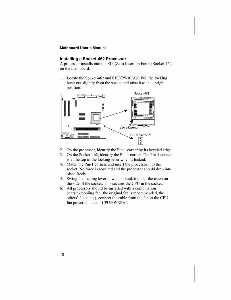
Installing a Socket-462 ProcessorA processor installs into the ZIF (Zero Insertion Force) Socket-462on the mainboard.
1. Locate the Socket-462 and CPU/PWRFAN. Pull the lockinglever out slightly from the socket and raise it to the uprightposition.
2. On the processor, identify the Pin-1 co3. On the Socket-462, identify the Pin-1
is at the top of the locking lever when 4. Match the Pin-1 corners and insert the
socket. No force is required and the prplace freely.
5. Swing the locking lever down and hoothe side of the socket. This secures the
6. All processors should be installed withheatsink/cooling fan (the original fan iothers’ fan is not), connect the cable frfan power connector CPU/PWRFAN.
Pin-1 Corner
Socket-462
CPU/PWRFAN
rner by its beveled edge.corner. The Pin-1 cornerit locked. processor into theocessor should drop into
k it under the catch on CPU in the socket. a combinations recommended, theom the fan to the CPU

2: Mainboard Installation
11
Install MemoryThe mainboard has two DIMM sockets for system memorymodules. You must install at least one memory module in order touse the mainboard.
For this mainboard, you must use 168-pin, 3.3V unbuffered PC100or PC133 SDRAM memory modules. You can install any sizememory module from 32 MB to 512MB, so the maximum memorysize is 2 x 512MB = 1GB.
The edge connectors on the memory modules have cut outs, whichcoincide with spacers in the DIMM sockets so that memorymodules can only be installed in the correct orientation.
To install a module, push the retaining latches at either end of thesocket outwards. Position the memory module correctly and insertit into the DIMM socket. Press the module down into the socket sothat the retaining latches rotate up and secure the module in placeby fitting into notches on the edge of the module.
DIMM2
DIMM1

Mainboard User’s Manual
12
Setting Jumper SwitchesJumpers are sets of pins which can be connected together withjumper caps. The jumper caps change the way the mainboardoperates by changing the electronic circuits on the mainboard. If ajumper cap connects two pins, we say the pins are SHORT. If ajumper cap is removed from two pins, the pins are OPEN.
Jumper JP4: Clear CMOS MemoryUse this jumper to clear the contents of the CMOS memory. Youmay need to clear the CMOS memory if the settings in the SetupUtility are incorrect and prevent your mainboard from operating.To clear the CMOS memory, disconnect all the power cables fromthe mainboard and then move the jumper cap into the CLEARsetting for a few seconds.
Function Jumper SettingNormal Operation Short Pins 2-3Clear CMOS Memory Short Pins 1-2
Jumper JP2: Keyboard Power On SelectorIf you enable the keyboard power on feature, you can use hot keyson your keyboard as a power on/off switch for the system.Note: The system must provide 1A on the +5VSB (+5V Standby)signal before using the Keyboard Power On function.
Function Jumper SettingDisable Keyboard Power On Short Pins 1-2Enable Keyboard Power On Short Pins 2-3
1JP4
JP2
1

2: Mainboard Installation
Install the MainboardInstall the mainboard in a system chassis (case). The board is anMicro ATX size mainboard with a twin-tier of I/O ports. You caninstall this mainboard in any ATX case. Ensure that your case hasan I/O cover plate that matches the ports on this mainboard.Install the mainboard in a case. Follow the instructions provided bythe case manufacturer using the hardware and internal mountingpoints on the chassis.
Connect the power connector from the power supply to the ATX1connector on the mainboard.If there is a cooling fan installed in the system chassis, connect thecable from the cooling fan to the CHSFAN fan power connectoron the mainboard.Connect the case switches and indicator LEDs to the J5 switch andLED connector header. See the illustration below for a guide to theheader pin assignments.
2221
Power LEDPins 2-4-6
SP
Turbo LEDPins 13-14
HDD LEDPins 15-16
21
Reset SwitchPins 17-18
Power ButtonPins 21-22
Suspend LEDPins 19-20
CHSFAN
ATX1
peakerins 1-3-5-7
J5
Suspend SwitchPins 11-12
13

Mainboard User’s Manual
14
Optional Extension BracketsFor this mainboard, you can also obtain a USB module extensionbracket. Install them by following the steps below.
Note: All the ribbon cables used on the extension brackets have ared stripe on the Pin-1 side of the cable.
Extended USB ModuleThis module bracket has two USB ports for more USB devices(USB port 3-4).
1. Locate2. Plug t3. In the
expanopeninsecure
JUSB1 Header
the JUSB1 header on the mainboard.he bracket cable onto the JUSB1 header.system chassis, remove a slot cover from one of thesion slots and install the extension bracket in theg. Use the screw that held the slot cover in place to the extension bracket to the chassis.
1

2: Mainboard Installation
Install Other DevicesInstall and connect any other devices in the system following thesteps below.
FloppThe msuppocapacInstalsupplydisk d
IDE DIDE dand CThe mIDE dmust SlaveconfigdeviceInstalsupplyPrima
IDE2FLOPPY
IDE1
1y Diainbort oneities ol your. Use
rive h
evicevicesD-ROainboevicesconfig. The dure th conn
l the d. Use
ry IDE
1
1
sk Driveard ships with a floppy or two drives. Drives caf 360K, 720K, 1.2MB, 1 drives and connect pow the cable provided to coeader FLOPPY.
es include hard disk driveM or DVD-ROM drivesard ships with an IDE c. If you connect two devure one of the drives as ocumentation of the IDe device as a Master or ects to the end of the caevice(s) and connect po the cable provided to co channel connector IDE
15
disk drive cable that cann be 3.5” or 5.25” wide, with.44MB, or 2.88MB.er from the system powernnect the drives to the floppy
s, high-density diskette drives,, among others.
able that can support one or twoices to a single cable, you
Master and one of the drives asE device will tell you how toSlave device. The Masterble.wer from the system powernnect the device(s) to the1 on the mainboard.
Mainboard User’s Manual
16
If you want to install more IDE devices, you can purchase a secondIDE cable and connect one or two devices to the Secondary IDEchannel connector IDE2 on the mainboard. If you have twodevices on the cable, one must be Master and one must be Slave.
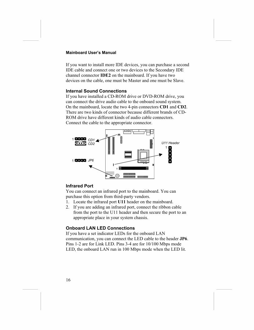
Internal Sound ConnectionsIf you have installed a CD-ROM drive or DVD-ROM drive, youcan connect the drive audio cable to the onboard sound system.On the mainboard, locate the two 4-pin connectors CD1 and CD2.There are two kinds of connector because different brands of CD-ROM drive have different kinds of audio cable connectors.Connect the cable to the appropriate connector.
Infrared PortYou can connect an infrared port to the mainboard. You canpurchase this option from third-party vendors.1. Locate the infrared port U11 header on the mainboard.2. If you are adding an infrared port, connect the ribbon cable
from the port to the U11 header and then secure the port to anappropriate place in your system chassis.
Onboard LAN LED ConnectionsIf you have a set indicator LEDs for the onboard LANcommunication, you can connect the LED cable to the header JP6.Pins 1-2 are for Link LED. Pins 3-4 are for 10/100 Mbps modeLED, the onboard LAN run in 100 Mbps mode when the LED lit.
CD1CD2
1U11 Header
1
JP61

2: Mainboard Installation
Expansion SlotsThis mainboard has two 32-bit PCI expansion slots, one AMR slotand one optional AGP slot.
Follow the s1. Locate t2. Remove3. Insert th
it firmly4. Secure t
the screw
AMR SlotThe AMR (Athat allows fDifferent terspecificationthat is approslot.
P
PCI2AMR1
CI117
teps below to install a PCI/AMR/AGP expansion card.he AGP, AMR or PCI slots on the mainboard. the slot cover for this slot from the system chassis.e expansion card edge connector into the slot and press down into it so that it is fully inserted.he expansion card bracket to the system chassis using
that held the slot cover in place.
udio Modem Riser) slot is an industry standard slotor the installation of a special audio/modem riser card.ritories have different regulations regarding thes of a modem card. You can purchase an AMR cardved in your area and install it directly into the AMR
AGP1


3: BIOS Setup Utility
19
Chapter 3BIOS Setup Utility
IntroductionThe BIOS Setup Utility records settings and information aboutyour computer such as the date and time, the kind of hardwareinstalled, and various configuration settings. Your computer usesthis information to initialize all the components when booting upand functions as the basis for coordination between systemcomponents.
If the Setup Utility configuration is incorrect, it may cause thesystem to malfunction. It can even stop your computer frombooting properly. If this happens, you can use the clear CMOSjumper to clear the CMOS memory used to store the configurationinformation, or you can hold down the Page Up key while youreboot your computer. Holding down the Page Up key also clearsthe setup information.
You can run the setup utility and manually make changes to theconfiguration. You might need to do this to configure some of thehardware that you install on or connect to the mainboard, such asthe CPU, system memory, disk drives, etc.
Mainboard User’s Manual
20
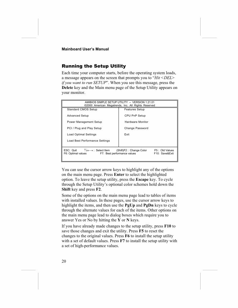
Running the Setup UtilityEach time your computer starts, before the operating system loads,a message appears on the screen that prompts you to “Hit <DEL>if you want to run SETUP”. When you see this message, press theDelete key and the Main menu page of the Setup Utility appears onyour monitor.
AMIBIOS SIMPLE SETUP UTILITY – VERSION 1.21.01©2000 American Megatrends, Inc. All Rights Reserved
Standard CMOS Setup Features Setup
Advanced Setup CPU PnP Setup
Power Management Setup Hardware Monitor
PCI / Plug and Play Setup Change Password
Load Optimal Settings Exit
Load Best Performance Settings
ESC: Quit ↑↓←→ : Select Item (Shift)F2 : Change Color F5 : Old ValuesF6: Optimal values F7: Best performance values F10: Save&Exit
You can use the cursor arrow keys to highlight any of the optionson the main menu page. Press Enter to select the highlightedoption. To leave the setup utility, press the Escape key. To cyclethrough the Setup Utility’s optional color schemes hold down theShift key and press F2.Some of the options on the main menu page lead to tables of itemswith installed values. In these pages, use the cursor arrow keys tohighlight the items, and then use the PgUp and PgDn keys to cyclethrough the alternate values for each of the items. Other options onthe main menu page lead to dialog boxes which require you toanswer Yes or No by hitting the Y or N keys.If you have already made changes to the setup utility, press F10 tosave those changes and exit the utility. Press F5 to reset thechanges to the original values. Press F6 to install the setup utilitywith a set of default values. Press F7 to install the setup utility witha set of high-performance values.

3: BIOS Setup Utility
21
Standard CMOS Setup PageUse this page to set basic information such as the date, the time,the IDE devices, and the diskette drives. If you press the F3 key,the system will automatically detect and configure the hard diskson the IDE channels.
AMIBIOS SETUP – STANDARD CMOS SETUP©2000 American Megatrends, Inc. All Rights Reserved
Date (mm/dd/yy) : Tue Oct 24, 2000Time (hh/mm/ss) : 14:26:53 LBA Blk PIO 32Bit Type Size Cyln Head WPcom Sec Mode Mode Mode ModePri Master : Auto OnPri Slave : Auto OnSec Master : Auto OnSec Slave : Auto On
Floppy Drive A : 1.44MB 3 1/2”Floppy Drive B : Not Installed
Month : Jan – Dec ESC : Exit Day : 01 – 31 ↑↓ : Select Item Year : 1901 – 2099 PU/PD/+/- : Modify (Shift)F2 : Color F3 : Detect All HDD
Date & Time Use these items to set the system date and timePri MasterPri SlaveSec MasterSec Slave
Use these items to configure devices connected tothe Primary and Secondary IDE channels. Toconfigure an IDE hard disk drive, choose Auto. If theAuto setting fails to find a hard disk drive, set it toUser, and then fill in the hard disk characteristics(Size, Cyls, etc.) manually. If you have a CD-ROMdrive, select the setting CDROM. If you have anATAPI device with removable media (e.g. a ZIPdrive or an LS-120) select Floptical.
Floppy Drive AFloppy Drive B
Use these items to set the size and capacity of thefloppy diskette drive(s) installed in the system.

Mainboard User’s Manual
22
Advanced Setup PageUse this page to set more advanced information about your system.Take some care with this page. Making changes can affect theoperation of your computer.
AMIBIOS SETUP – ADVANCED SETUP(C) 2000 American Megatrends, Inc. All Rights Reserved
Trend ChipAway Virus EnabledQuick Boot Enabled1st Boot Device IDE-02nd Boot Device Floppy3rd Boot Device CDROMTry Other Boot Devices YesS.M.A.R.T. for Hard Disks DisabledBootUp Num-Lock OnFloppy Drive Swap DisabledFloppy Drive Seek DisabledPassword Check SetupBoot To OS/2 > 64MB NoL1 Cache EnabledSystem BIOS Cacheable Enabled
ESC : Quit ↑↓←→ : Select ItemF1 : Help PU/PD/+/- : ModifyF5 : Old Values (Shift)F2 : ColorF6 : Load Optimal valuesF7 : Load Best performance values
Trend ChipAwayVirus
This mainboard has built-in virus protection in thefirmware. Use this item to enable or disable thebuilt-in virus protection.
Quick Boot If you enable this item, the system starts up morequickly be elimination some of the power on testroutines.
1st Boot Device2nd Boot Device3rd Boot Device
Use these items to determine the device order thecomputer uses to look for an operating system toload at start-up time.
Try Other BootDevice
If you enable this item, the system will also searchfor other boot devices if it fails to find an operatingsystem from the first two locations.
S.M.A.R.T. forHard Disks
Enable this item if any IDE hard disks support theS.M.A.R.T. (Self-Monitoring, Analysis and ReportingTechnology) feature.
BootUp Num-Lock
This item determines if the Num Lock key is activeor inactive at system start-up time.
Floppy DriveSwap
If you have two diskette drives installed and youenable this item, drive A becomes drive B and driveB becomes drive A.

3: BIOS Setup Utility
23
Floppy DriveSeek
If you enable this item, your system will check allfloppy disk drives at start up. Disable this itemunless you are using an old 360KB drive.
Password Check If you have entered a password for the system, usethis item to determine, if the password is required toenter the Setup Utility (Setup) or required both atstart-up and to enter the Setup Utility (Always).
Boot to OS/2 >64MB
Enable this item if you are booting the OS/2operating system and you have more than 64MB ofsystem memory installed.
L1 Cache Leave this item enabled since all the processorsthat can be installed on this board have internalcache memory.
System BIOSCacheable
If you enable this item, a segment of the systemBIOS will be cached to main memory for fasterexecution.
Power Management Setup PageThis page sets some of the parameters for system powermanagement operation.
AMIBIOS SETUP – POWER MANAGEMENT SETUP(C) 2000 American Megatrends, Inc. All Rights Reserved
Power Management/APM DisabledStandby Time Out DisabledSuspend Time Out DisabledDisplay Time Out DisabledHard Disk Time Out DisabledRing On Power On DisabledKeyboard Power On DisabledRTC Alarm Power On Disabled RTC Alarm Date 15 RTC Alarm Hour 12 RTC Alarm Minute 30 RTC Alarm Second 30
ESC : Quit ↑↓←→ : Select ItemF1 : Help PU/PD/+/- : ModifyF5 : Old Values (Shift)F2 : ColorF6 : Load Optimal valuesF7 : Load Best performance values
PowerManagement/APM
Use this item to enable or disable a powermanagement scheme. If you enable powermanagement, you can use the items below to setthe power management operation. Both APM andACPI are supported.

Mainboard User’s Manual
24
Standby Time Out This sets the timeout for Standby mode inminutes. If the time selected passes without anysystem activity, the computer will enter power-saving Standby mode.
Suspend Time Out This sets the timeout for Suspend mode inminutes. If the time selected passes without anysystem activity, the computer will enter power-saving Suspend mode.
Display Time Out This sets the timeout for display device in minutes.If the time selected passes without any displayactivity, the display will enter power-saving mode.
Hard Disk TimeOut
This sets the timeout for hard disk in minutes. Ifthe time selected passes without any hard diskactivity, the disk will enter power-saving mode.
Ring On Power On The system can be turned off with a softwarecommand. If you enable this item, the system canautomatically resume if there is an incoming callon the Fax/Modem. You must use an ATX powersupply in order to use this feature.
KeyBoard PowerOn
If you enable this item, you can turn the system onand off by pressing hot keys on the keyboard. Youmust enable the Keyboard Power On jumper inorder to use this feature.
RTC Alarm PowerOn / Date / Hour /Minute / Second
The system can be turned off with a softwarecommand. If you enable this item, the system canautomatically resume at a fixed time based on thesystem’s RTC (realtime clock). Use the itemsbelow this one to set the date and time of thewake-up alarm. You must use an ATX powersupply in order to use this feature.

3: BIOS Setup Utility
25
PCI / Plug and Play Setup PageThis page sets some of the parameters for devices installed on thePCI bus and devices that use the system plug and play capability.
AMIBIOS SETUP – PCI / PLUG AND PLAY SETUP(C) 2000 American Megatrends, Inc. All Rights Reserved
Plug and Play Aware O/S YesShare Memory Size 16MBO/S Control NormalPrimary Graphics Adapter PCIAllocate IRQ for PCI VGA Yes
ESC : Quit ↑↓←→ : Select ItemF1 : Help PU/PD/+/- : ModifyF5 : Old Values (Shift)F2 : ColorF6 : Load Optimal valuesF7 : Load Best performance values
Plug and PlayAware O/S
Enable this item if you are using an O/S thatsupports Plug and Play such as Windows 95 or98.
Share MemorySize
This item lets you allocate a portion of the mainmemory for use by the onboard VGA display.
O/S Control This item lets you select Japanese operatingsystem or not.
Primary GraphicsAdapter
This item indicates if the primary graphics adapteruses the PCI or the AGP bus. The default PCIsetting still lets the onboard display work andallows the use of a second display card installed ina PCI slot.
Allocate IRQ forPCI VGA
If this item is enabled, an IRQ will be assigned tothe PCI VGA graphics system. You set this valueto No to free up an IRQ.
Load Optimal SettingsIf you select this item and press Enter a dialog box appears. If youpress Y, and then Enter, the Setup Utility loads a set of fail-safedefault values. These default values are not very demanding andthey should allow your system to function with most kinds ofhardware and memory chips.

Mainboard User’s Manual
26
Load Best Performance SettingsIf you select this item and press Enter a dialog box appears. If youpress Y, and then Enter, the Setup Utility loads a set of best-performance default values. These default values are quitedemanding and your system might not function properly if you areusing slower memory chips or other low-performance components.
Features Setup PageThis page sets some of the parameters for peripheral devicesconnected to the system.
AMIBIOS SETUP – PERIPHERAL SETUP(C) 2000 American Megatrends, Inc. All Rights Reserved
OnBoard FDC EnabledOnBoard Serial Port 3F8h/COM1OnBoard IR Port DisabledOnBoard Parallel Port 378h Parallel Port Mode SPP Parallel Port IRQ 7 Parallel Port DMA N/AOnBoard Game Port 201hOnBoard MIDI Port 300h MIDI Port IRQ 10OnBoard PCI IDE BothAC’97 Sound EnabledAC’97 Modem EnabledOnBoard LAN EnabledUSB Function Support EnabledUSB Function for DOS Disabled
ESC : Quit ↑↓←→ : Select ItemF1 : Help PU/PD/+/- : ModifyF5 : Old Values (Shift)F2 : ColorF6 : Load Optimal valuesF7 : Load Best performance values
OnBoard FDC Use this item to enable or disable the onboardfloppy disk drive interface.
OnBoard SerialPort
Use this item to enable or disable the onboardCOM1 serial port, and to assign a port address.
OnBoard Ir Port Use this item to define the protocol for an infraredport if you have installed an optional IR port. Thechoices are IrDA and ASKIR.
Onboard ParallelPort
Use this item to enable or disable the onboardLPT1 parallel port, and to assign a port address.The Auto setting will detect and available address.

3: BIOS Setup Utility
27
Parallel Port Mode Use this item to set the parallel port mode. Youcan select SPP (Standard Parallel Port), ECP(Extended Capabilities Port), EPP (EnhancedParallel Port), or ECP + EPP.
Parallel Port IRQ Use this item to assign either IRQ 5 or 7 to theparallel port.
Parallel Port DMA Use this item to assign a DMA channel to theparallel port. The options are 0, 1 and 3.
OnBoard GamePort
Use this item to enable or disable the onboardgame port, and to assign a port address.
OnBoard MIDI Port Use this item to enable or disable the onboardMIDI port, and to assign a port address.
MIDI Port IRQ Use this item to assign an IRQ to the MIDI port.Onboard PCI IDE Use this item to enable or disable either or both of
the onboard Primary and Secondary IDEchannels.
AC’97 Sound This item enables or disables the onboard AC’97audio chip.
AC’97 Modem This item enables or disables the onboard AC’97modem chip.
OnBorad LAN This item enables or disables the onboard LANchip.
USB FunctionSupport
Enable this item if you plan to use the USB portson this mainboard.
USB Function forDOS
Enable this item if you plan to use the USB portson this mainboard in a DOS environment.

Mainboard User’s Manual
28
CPU PnP Setup PageThis page lets you manually configure the mainboard for the CPU.The system will automatically detect the kind of CPU that youhave installed and make the appropriate adjustments to the itemson this page.
AMIBIOS SETUP – CPU PnP SETUP©2000 American Megatrends, Inc. All Rights Reserved
CPU BRAND AMD K7CPU Type AthlonCPU Speed 933 MHzCPU Core Voltage 1.728 VCPU Ratio 7.0xCPU Frequency 133 MHzDRAM Frequency 133 MHz
ESC : Quit ↑↓←→ : Select Item F1 : Help PU/PD/+/- : Modify F5 : Old Values (Shift)F2 : Color F6 : Load Optimal values F7 : Load Best performance values
CPU BRAND/Type/Core Voltage/Ratio/Frequency
These items show the kind, core voltage, ratio andfrequency of CPU that has installed in yoursystem.
CPU Speed Use this item to set the CPU speed that hasinstalled in your system.
DRAM Frequency Use this item to set the frequency of DRAM thathas installed in your system.
Note: If you manually set the wrong speed and the system won’trun properly, press the Page Up key while the system is bootingand a default setting will replace the incorrect CPU setting.

3: BIOS Setup Utility
29
Hardware Monitor PageThis page sets some of the parameters for the hardware monitoringfunction of this mainboard.
AMIBIOS SETUP – HARDWARE MONITOR(C) 2000 American Megatrends, Inc. All Rights Reserved
--- Hardware Monitor ---CPU Temperature 30°C/86°FSystem TemperatureCPU Fan SpeedSystem Fan SpeedVcore 2.000 VVcc25v 2.500 VVcc3 3.300 V+12V 12.000 V–12V -12.000 VSB3V 3.300 VSB5V 5.000 VVoltage Battery 3.000 V
ESC : Quit ↑↓←→ : Select ItemF1 : Help PU/PD/+/- : ModifyF5 : Old Values (Shift)F2 : ColorF6 : Load Optimal valuesF7 : Load Best performance values
CPU / SystemTemperature
These items display CPU and system temperaturemeasurement.
FANs & VoltageMeasurements
These items indicate cooling fan speeds in RPMand the various system voltage measurements.
Change PasswordIf you highlight this item and press Enter, a dialog box appearswhich lets you enter a Supervisor password. You can enter no morethan six letters or numbers. Press Enter after you have typed in thepassword. A second dialog box asks you to retype the password forconfirmation. Press Enter after you have retyped it correctly. Thepassword is then required to access the Setup Utility or for that andat start-up, depending on the setting of the Password Check itemin Advanced Setup.
Change or Remove the PasswordHighlight this item, press Enter and type in the current password.At the next dialog box, type in the new password, or just pressEnter to disable password protection.

Mainboard User’s Manual
30
ExitHighlight this item and press Enter to save the changes that youhave made in the Setup Utility configuration and exit the program.When the Save and Exit dialog box appears, press Y to save andexit, or press N to exit without saving.

4: Software & Applications
31
Chapter 4Software & Applications
IntroductionThe support software CD-ROM that is included in the mainboardpackage contains all the drivers and utility programs needed toproperly run our products. Below you can find a brief descriptionof each software program, and the location for your mainboardversion. More information on some programs is available in aREADME file, located in the same directory as the software.If the operating system used in your system is Windows 98, itwill automatically install all the drivers and utilities for yourboard. See the Auto-Installing under Windows 98 section.
Installing Support SoftwareThe software on the support CD-ROM is for Windows 95/NT/2000and Windows 98. The installation procedure differs depending onwhich Operating System you have, but the automatic installation isnow for Win98 only.
Installing under Windows 95/NT/2000To install support software for Windows 95/NT/2000 follow thisgeneral procedure:1. Insert the support CD-ROM disc in the CD-ROM drive.(The system might get an error message from the PnP function.Don’t care the message. You don’t really need that file to installthe drivers)2. Use My Computer or Windows Explorer to look at the
directory structure. You must use the Open command in theright-button menu. Double-clicking on the drive icon willresult in an error message because the disc’s AutoRun featuredoesn’t work in Windows 95/NT/2000.
3. Execute the EXE file name given in the description below.

Mainboard User’s Manual
32
Note: The correct path name for each software driver is provided,where D: identifies the CD-ROM drive letter – modify if necessary.
AGP DriverThe AGP Drivers allows the system to properly manage the AGPslot on the mainboard. Find the driver here:♦ D:\VGA\AGP\SiS730S\
Display Drivers and SoftwareFind the Display drivers and software here:♦ D:\VGA\SiS730S\
Audio DriverThe Audio driver allows the system to use the onboard audiocircuitry. Find the driver and audio application here:♦ D:\SOUND\Driver\SiS\♦ D:\SOUND\Gamut\
Network Adapter DriverFind the network adapter driver here:♦ D:\LAN\SiS900\
AMR Modem DriverFind the driver here:♦ D:\Modem\Driver\AMR\PCtel\
USB DriverThe USB Driver allows the system to recognize the USB ports onthe mainboard. You need to install this driver if you are runningWindows 95. Windows 95 OSR2 does not require this driver.This driver is available for:♦ Win95 – D:\USB\EUSBSUPP\USBSUPP.EXE♦ Win95 (Chinese) – D:\USB\CUSBSUPP\CUSBSUPP.EXE
3Deep SoftwareFind the software here:♦ D:\3Deep\3Deep 3.3\Setup.EXE

4: Software & Applications
33
BIOS Update UtilityThe BIOS Update utility allows you to update the BIOS file on themainboard to a newer version. You can download the latest versionof the BIOS setup available for your mainboard from the website.♦ D:\UTILITY\AMINF323.EXE
PC-Cillin SoftwareThe PC-cillin software program provides anti-virus protection foryour system. This program is available for:♦ DOS – D:\PC-CILLIN\DOS\PCSCAN.EXE♦ Win9x – D:\PC-CILLIN\WIN98\SETUP.EXE
Auto-installing under Windows 98The support software CD-ROM disc loads automatically underWindows 98. When you insert the CD-ROM disc in the systemCD-ROM drive the Autorun feature will automatically bring up theinstall screen. The screen has three buttons on it, Setup, BrowseCD and Exit. See the following screen illustration.
When you click on the Setup button the software installationprogram will run and you can select what kind of installation youwant to do, as explained later in this section.The Browse CD button is the standard Windows command thatallows you to examine the contents of the disc using the Windows98 file browsing interface.The Exit button closes the Auto Setup window. To run theprogram again, reinsert the CD-ROM disc in the drive or click on

Mainboard User’s Manual
34
AutoRun in the context sensitive menu for the CD-ROM drive iconin a file browser window.
Installing Software with Auto SetupTo install support software for the system board follow thisprocedure:1. Click on the Setup button. The install program will load and
display the following screen. Click the Next button.
2. Select the items that you want to setup by clicking on it (thedefault options are recommended). Click the Next button toproceed.
3. The support software will automatically install.
Once any of the installation procedures start, software isautomatically installed in sequence. You will need to follow theonscreen instructions, confirm commands and allow the computerto restart as few times as is needed to complete installing whatever

4: Software & Applications
35
software you selected to install. When the process is finished, allthe support software will be installed and working.
There are some utilities that you have to manually install if youneed, check to the above section.