Embed Size (px)
Citation preview
Documentation Author
F.Lambercy and G.Caprari for K-Team S.A.Rue Galilee 91400 Yverdon-les-bainsSwitzerland
email: [email protected]: www.k-team.com
Trademark Acknowledgments:
IBM PC: International Business Machine Corp.Khepera: K-Team and LAMI
Legal Notice:
• The content of this manual is subject to change without notice.
• All effort have been made to ensure the accuracy of the content ofthis manual. However, should any error be detected, please informK-Team S.A.
• The above notwithstanding K-Team can assume no responsibility forany error in this manual.
Khepera III manual ver 2.2 1
Table Of Contents
1 Introduction 4
1.1 How to Use this Manual . . . . . . . . . . . . . . . . . . . . . 41.2 Safety Precaution . . . . . . . . . . . . . . . . . . . . . . . . . 41.3 Recycling . . . . . . . . . . . . . . . . . . . . . . . . . . . . . 5
2 Unpacking and Inspection 6
3 The Robot and Its Accessories 7
3.1 The Khepera III Robot . . . . . . . . . . . . . . . . . . . . . 73.1.1 Overview . . . . . . . . . . . . . . . . . . . . . . . . . 73.1.2 ON-OFF Battery Switch . . . . . . . . . . . . . . . . . 83.1.3 Indication LEDs . . . . . . . . . . . . . . . . . . . . . 83.1.4 Serial connector . . . . . . . . . . . . . . . . . . . . . 93.1.5 Cable unroller connector . . . . . . . . . . . . . . . . . 103.1.6 USB connector . . . . . . . . . . . . . . . . . . . . . . 103.1.7 How to plug a KoreBotLE . . . . . . . . . . . . . . . . 11
3.2 Motors and motor control . . . . . . . . . . . . . . . . . . . . 123.2.1 Speed . . . . . . . . . . . . . . . . . . . . . . . . . . . 14
3.3 Infra-red Proximity sensors . . . . . . . . . . . . . . . . . . . 163.3.1 Ambient light measurements . . . . . . . . . . . . . . 173.3.2 Reflected light measurements (proximity) . . . . . . . 17
3.4 Ultrasonic sensors . . . . . . . . . . . . . . . . . . . . . . . . 183.5 Battery . . . . . . . . . . . . . . . . . . . . . . . . . . . . . . 193.6 Power Supply . . . . . . . . . . . . . . . . . . . . . . . . . . . 19
4 Connections 20
4.1 Configuration for batteries charge . . . . . . . . . . . . . . . . 204.2 Configuration for Robot-Computer Communication in standalone 214.3 Configuration for Robot-Computer Communication with KoreBotLE 22
4.3.1 Serial link . . . . . . . . . . . . . . . . . . . . . . . . . 224.3.2 USB link . . . . . . . . . . . . . . . . . . . . . . . . . 23
4.4 Bluetooth Communication . . . . . . . . . . . . . . . . . . . . 244.4.1 Bluetooth communication with KheperaIII . . . . . . 244.4.2 Bluetooth communication with KoreBotLE . . . . . . 254.4.3 Log On the KoreBotLE with a Bluetooth connection . 25
K-Team S.A. 2
5 Serial Communication Mode 26
5.1 Testing the primary serial link . . . . . . . . . . . . . . . . . 265.2 Testing the secondary serial link . . . . . . . . . . . . . . . . 275.3 Serial communication protocol . . . . . . . . . . . . . . . . . 28
5.3.1 Testing a simple interaction . . . . . . . . . . . . . . . 28
6 KoreBotLE programming 30
A Communication protocol 33
Khepera III manual ver 2.2 3
1 Introduction
1.1 How to Use this Manual
This manual is introducing the Khepera III robot. For a quick start andoverview of the robot’s functions, please read chapter 1 to 4.
Refer to the following summary if a particular information is needed.If the manual does not cover a particular problem, many more technicaldocumentation is available online from K-Team website (www.k-team.com)and especially a Frequently Asked Question document to solve most commonproblems and questions.
Unpacking and Inspection: Khepera’s package description.
The robot and its accessories: Khepera Hardware overview and mainfunctions and accessories description.
Connections: detailed cables connections for various usage.
Serial Communication mode: detailed description for the Serial com-munication mode between a computer and the robot.
1.2 Safety Precaution
Check the unit’s operating voltage before operation.
It must be identical with that of your local power supply. The operatingvoltage is indicated on the nameplate at the rear of the power supply.
All connnections (including extension addition or disconnection) mustbe made when the robot and the interface are switched OFF. Otherwisedamages can occur.Switch OFF the robot if you will not use it for more than a day.
Disconnect the power supply removing it from the wall socket.Do not manually force any mechanical movement.
Avoid to force, by any mechanical way, the movement of the wheels orany other part.
If you have any question or problem concerning the robot, please contactyour local Khepera dealer.
K-Team S.A. 4
1.3 Recycling
Think about the end of life of your robot! Parts of the robot can be recycledand it is important to do so. It is for instance important to keep batteriesout of the solid waste stream. When you throw away a battery, it eventuallyends up in a landfill or municipal incinerator. These batteries, which containheavy metals, can contribute to the toxicity levels of landfills or incineratorash. By recycling the batteries through recycling programs, you can help tocreate a cleaner and safer environment for generations to come. For thosereasons please take care to the recycling of your robot at the end of its lifecycle, for instance sending back the robot to the manufacturer or to yourlocal dealer.
Thanks for your contribution to a cleaner environment!
Khepera III manual ver 2.2 5
2 Unpacking and Inspection
Open the bag and check each item in the box. You should having thefollowing material.
1. Khepera III robot
2. KoreBotLE ( not included in the Khepera III base package )
3. Power Supply with a primary plug
4. Battery Pack
5. Optional KoreConnect
K-Team S.A. 6
3 The Robot and Its Accessories
3.1 The Khepera III Robot
3.1.1 Overview
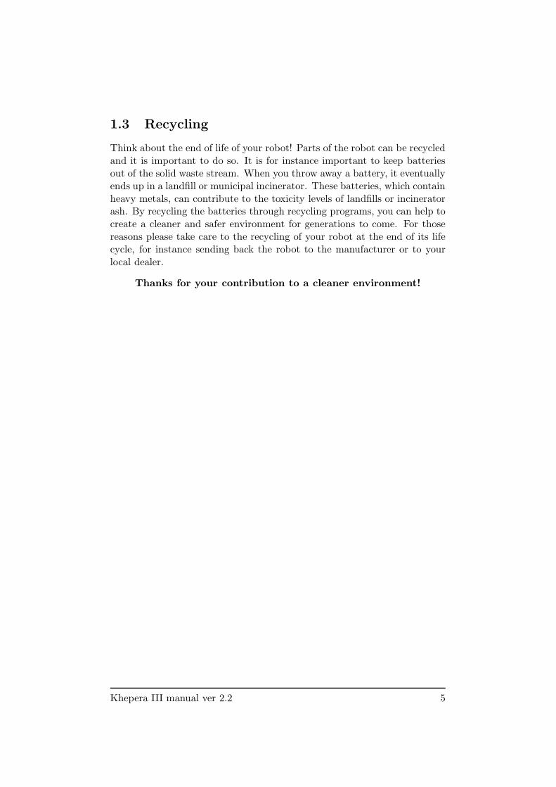
Figure 3.1: Overview of the Khepera III robot.
Make an external inspection of the robot. Note the location of the fol-lowing parts:
1. Infrared sensors.
2. Ultrasonic sensors.
3. Main serial connector.
4. USB miniAB connector.
5. Power jack connector.
6. Reset.
7. On / Off.
8. Cable unroller connector.
K-Team S.A. 7
3.1.2 ON-OFF Battery Switch
It allows the user to switch the robot ON or OFF. When ON, the robot ispowered. The robot may even be powered without the battery pack usingthe external power supply connector. See figure 3.1 number 7.
3.1.3 Indication LEDs
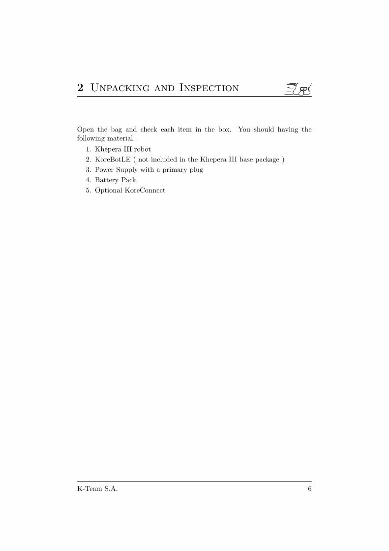
The Khepera III has six indication LEDs, two for the battery charger, onefor the Power ON, one for the state of the motors controller and two pro-grammables by the end-user (see figure 3.2).
When the Motor controller state LED is on, one of the two motor con-troller is in error mode. This could append when a motor is blocked ora current limit is detected. In this case the controller must be reset bythe dsPIC (’M’ command in serial interface mode or call ’initKH3()’ in aKoreBotLE program).
For the battery charger, the red one indicates that charge is in progressand the green one signals when the charge is complete. If there’s no batterypack when you plug an external power supply, the green one will turn on.
The led 5 and 6 can be set by the user with ’L’ command. See annexeA Serial communication protocol.
Figure 3.2: LEDs of the Khepera III.
1. Motor Controllers state LED (redD).
2. Power ON LED (green).
3. Charge completed LED (green).
4. Charge in progress LED (red).
5. Programmable LED (green).
6. Programmable LED (red).
Khepera III manual ver 2.2 8
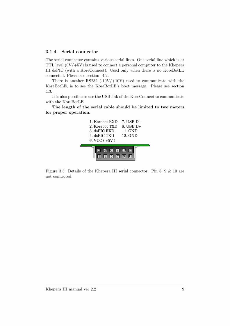
3.1.4 Serial connector
The serial connector contains various serial lines. One serial line which is atTTL level (0V/+5V) is used to connect a personal computer to the KheperaIII dsPIC (with a KoreConnect). Used only when there is no KoreBotLEconnected. Please see section 4.2.
There is another RS232 (-10V/+10V) used to communicate with theKoreBotLE, ie to see the KoreBotLE’s boot message. Please see section4.3.
It is also possible to use the USB link of the KoreConnect to communicatewith the KoreBotLE.
The length of the serial cable should be limited to two meters
for proper operation.
119531 7
12. GND
11. GND
7. USB D−
8. USB D+
1. Korebot RXD
2. Korebot TXD
3. dsPIC RXD
4. dsPIC TXD
6. VCC ( +5V )
12108642
Figure 3.3: Details of the Khepera III serial connector. Pin 5, 9 & 10 arenot connected.
Khepera III manual ver 2.2 9
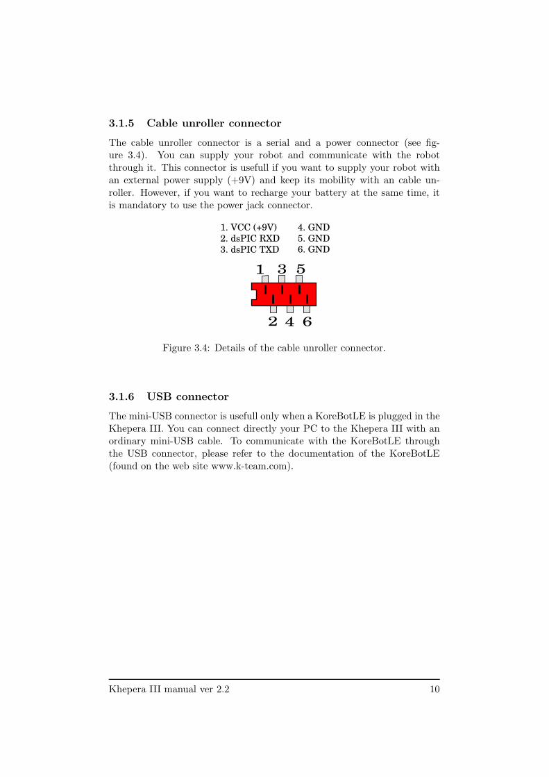
3.1.5 Cable unroller connector
The cable unroller connector is a serial and a power connector (see fig-ure 3.4). You can supply your robot and communicate with the robotthrough it. This connector is usefull if you want to supply your robot withan external power supply (+9V) and keep its mobility with an cable un-roller. However, if you want to recharge your battery at the same time, itis mandatory to use the power jack connector.
6. GND
4. GND
5. GND
1. VCC (+9V)
2. dsPIC RXD
3. dsPIC TXD
1
2
3 5
4 6
Figure 3.4: Details of the cable unroller connector.
3.1.6 USB connector
The mini-USB connector is usefull only when a KoreBotLE is plugged in theKhepera III. You can connect directly your PC to the Khepera III with anordinary mini-USB cable. To communicate with the KoreBotLE throughthe USB connector, please refer to the documentation of the KoreBotLE(found on the web site www.k-team.com).
Khepera III manual ver 2.2 10
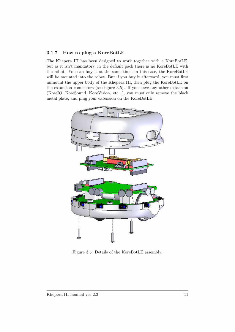
3.1.7 How to plug a KoreBotLE
The Khepera III has been designed to work together with a KoreBotLE,but as it isn’t mandatory, in the default pack there is no KoreBotLE withthe robot. You can buy it at the same time, in this case, the KoreBotLEwill be mounted into the robot. But if you buy it afterward, you must firstunmount the upper body of the Khepera III, then plug the KoreBotLE onthe extansion connectors (see figure 3.5). If you have any other extansion(KoreIO, KoreSound, KoreVision, etc...), you must only remove the blackmetal plate, and plug your extension on the KoreBotLE.
Figure 3.5: Details of the KoreBotLE assembly.
Khepera III manual ver 2.2 11
3.2 Motors and motor control
Each wheel is moved by a DC motor coupled with the wheel through a 43.2:1reduction. The motor itself having a 27:1 reduction and the gear box havinga 1.6:1 reduction. The motor has its own embedded incremental encoder,placed on the motor axis, gives 16 pulses per revolution of the motor. Thisallows a resolution of 691.2 per revolution of the wheel that corresponds to54 pulses per ten millimeter of path of the robot (diameter of the wheel =41mm, thus each revolution the robot make 128.8mm). By default, the robotis set in mode encoder resolution x4, in this case for each wheel revolutionthe controller motor make 2764 measures. The other encoder configurationmode is 2x (1382 measures/turn).
Reminder: 1 revolution = 128.8mm = 2764 measures.Each motor is driven by its own motor controller implemented in a
PIC18F4431. The PIC has direct control on the motor power through adouble H bridge and can read the pulses of the incremental encoder.
The motor control block acts as slave devices on the I2C bus. When theKoreBotLE is not connected to the Khepera III robot, the main robot CPUwill turns itself into an i2c master. When the KoreBotLE is connectedm, itbecomes the i2c master.
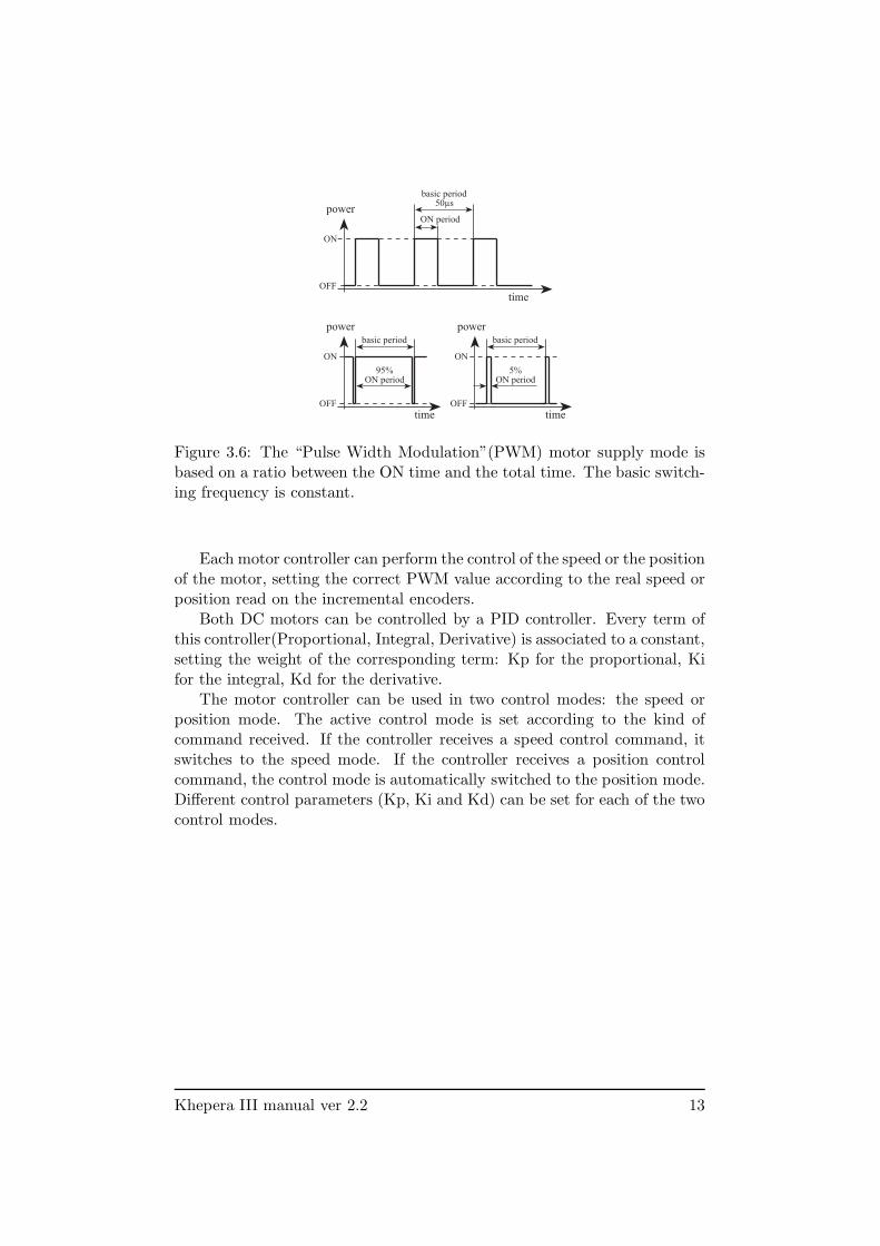
Each motor controller switches its motor ON and OFF at a given fre-quency and during a given time. By this way, the motor react to the timeaverage of the power supply, which can be modified by changing the periodthe motor is switched ON. This means that only the ratio between ON andOFF periods is modified, as illustrated in figure 3.6. This power controlmethod is called ”pulse width modulation” (PWM). The PWM value isdefined as the time the motor is switched ON.
Khepera III manual ver 2.2 12
time
power
OFF
ON
basic period50µs
ON period
time
power
OFF
ON
basic period
95%ON period
time
power
OFF
ON
basic period
5%ON period
Figure 3.6: The “Pulse Width Modulation”(PWM) motor supply mode isbased on a ratio between the ON time and the total time. The basic switch-ing frequency is constant.
Each motor controller can perform the control of the speed or the positionof the motor, setting the correct PWM value according to the real speed orposition read on the incremental encoders.
Both DC motors can be controlled by a PID controller. Every term ofthis controller(Proportional, Integral, Derivative) is associated to a constant,setting the weight of the corresponding term: Kp for the proportional, Kifor the integral, Kd for the derivative.
The motor controller can be used in two control modes: the speed orposition mode. The active control mode is set according to the kind ofcommand received. If the controller receives a speed control command, itswitches to the speed mode. If the controller receives a position controlcommand, the control mode is automatically switched to the position mode.Different control parameters (Kp, Ki and Kd) can be set for each of the twocontrol modes.
Khepera III manual ver 2.2 13
3.2.1 Speed
Used in speed mode, the controller has as input a speed value of the wheels,and controls the motor to keep this wheel speed.
The speed value is a division of a constant value by the time betweenencoder pulsations. In default mode (encoder resolution x4 and postscaler1:4), a measure is made four times every pulse. Then each revolution of thewheel, 2764 measures are made. The constant value is defined by the maxi-mum time multiplied by 256 (0xFFFF * 256 = 16’776’960). This operationallows a better PID calculation for the lower speed.
MotorSpeed =16′776′960
T imer5value
To convert into a real time, use the following calculation (this time isthe delay between two measures):
T ime =T imer5valuePostscaler
fosc/4
Tmr5Prescaler
Where fosc = 20MHz and Tmr5Prescaler = 8 (default).To get the real speed in mm/s:
RealSpeed =WheelCircumference
T ime ∗ 2764
Where WheelCircumference is 128.8mm and 2764 correspond to the numberof measures per revolution of the wheel.
Here’s an example with MotorSpeed = 20’000, Tmr5Prescaler = 8, Postscaler= 4 and encoder resolution = x4
T imer5value =16′776′960
20′000= 839
T ime =839
4
20′000′000/4
8
= 0.336[ms]
RealSpeed =128.8
0.000336 ∗ 2764= 138.9[mm/s]
RealSpeed =MotorSpeed
Kspeed[mm/s]
Where Kspeed is 144.01 when default configuration is used.The maximum reachable speed is 48’000 (= 333 mm/s) in open loop,
and 43’000 (= 298 mm/s) in regulation mode. And the minimum is 2’000(= 13.9 mm/s) with regulation control.
Khepera III manual ver 2.2 14
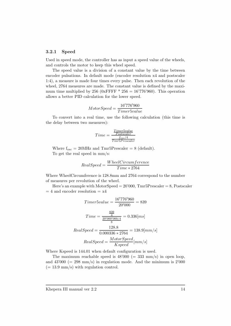
Used in position profile mode (’F’ command), the controller has as in-put a target position of the wheel, an acceleration and a maximal speed.Using this values, the controller accelerates the wheel until the maximalspeed is reached, and decelerates in order to reach the target position. Thismovement follows a trapezoidal speed profile, as described in figure 3.7.
time
time
po
siti
on
spee
d
acc -acc
start position
target position
max_speed
Figure 3.7: Speed profile to reach a target position with a fixed acceleration(acc) and maximal speed (max speed).
The input values and the control mode of this controller can be changedat every moment. The controller will update and execute the new profilein the position mode, or control the wheel speed following the new value inthe speed mode.
First configure the speed profile (’J’ command) with the needed param-eters. Then you can perform a move with the position profile mode (’F’command). See annexe A for more details about communication protocole.
Khepera III manual ver 2.2 15
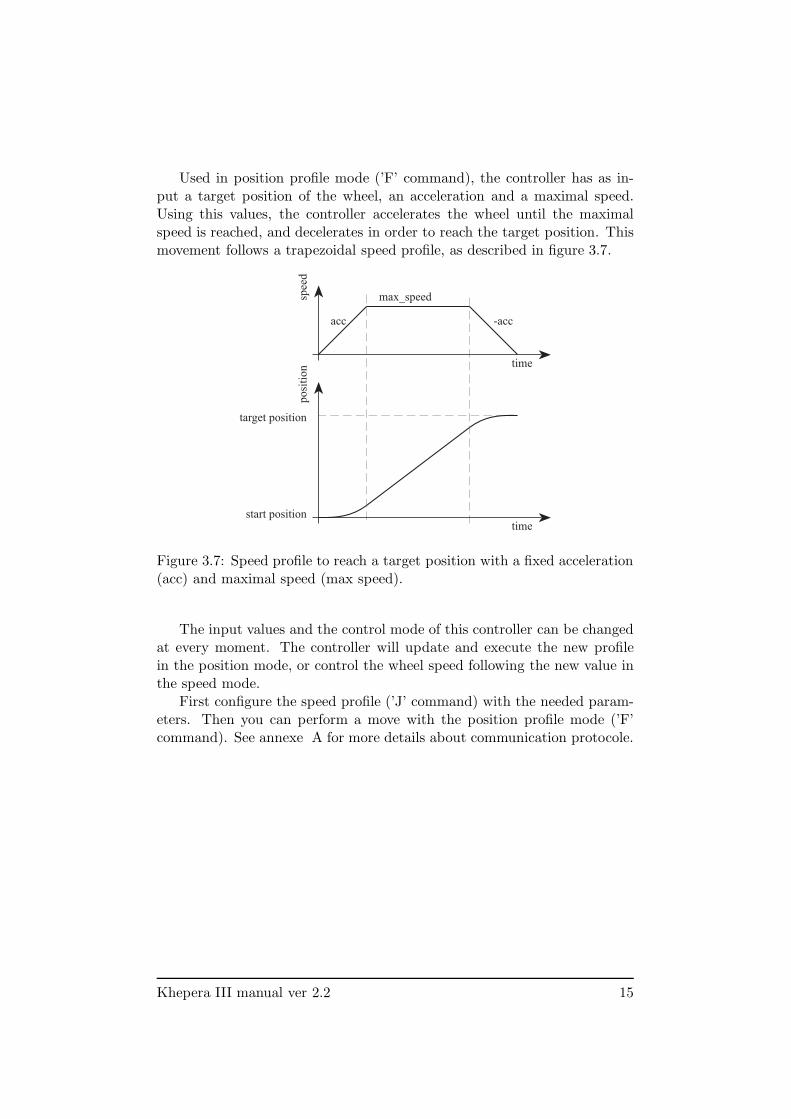
3.3 Infra-red Proximity sensors
Khepera III hase nine sensors placed around the robot and two placed onthe bottom. The latters allow experiments like line following. They arepositioned and numbered as shown in figure 3.9.
Figure 3.8: Bottom view of the IR sensors
These sensors embed an infra-red light emitter and a receiver. For de-tailed description, please refer to the manufacturer’s datasheet. The eightsensors are TCRT5000, reflective optical sensors from Vishay Telefunken.
Khepera III manual ver 2.2 16
This sensor device allows two measures:- The normal ambient light. This measure is made using only the re-
ceiver part of the device, without emitting light with the emitter. Anew measurement is made every 33 ms. During the 33 ms, the elevensensors are read in a sequential way every 3 ms. The value returnedat a given time is the result of the last measurement made.
- The light reflected by obstacles (= proximity). This measure is madeemitting light using the emitter part of the device. The returnedvalue is the difference between the measurement made emitting lightand the light measured without light emission (ambient light). A newmeasurement is made every 33 ms. During the 33 ms, the elevensensors are read in a sequential way every 3 ms. The value returnedat a given time is the result of the last measurement made.
The output of each measurement is an analog value converted to a 12bit digital value . The following two sections illustrate the meaning of this12 bit values.
3.3.1 Ambient light measurements
Ambient light measurement is strongly influenced by the robot’s environ-ment. Depending on the light source type, color, and distance, ambientlight measurement profile might vary. It is not recommended to use
light source with large emission in the infrared range, as this could
confuse the IR sensors.
3.3.2 Reflected light measurements (proximity)
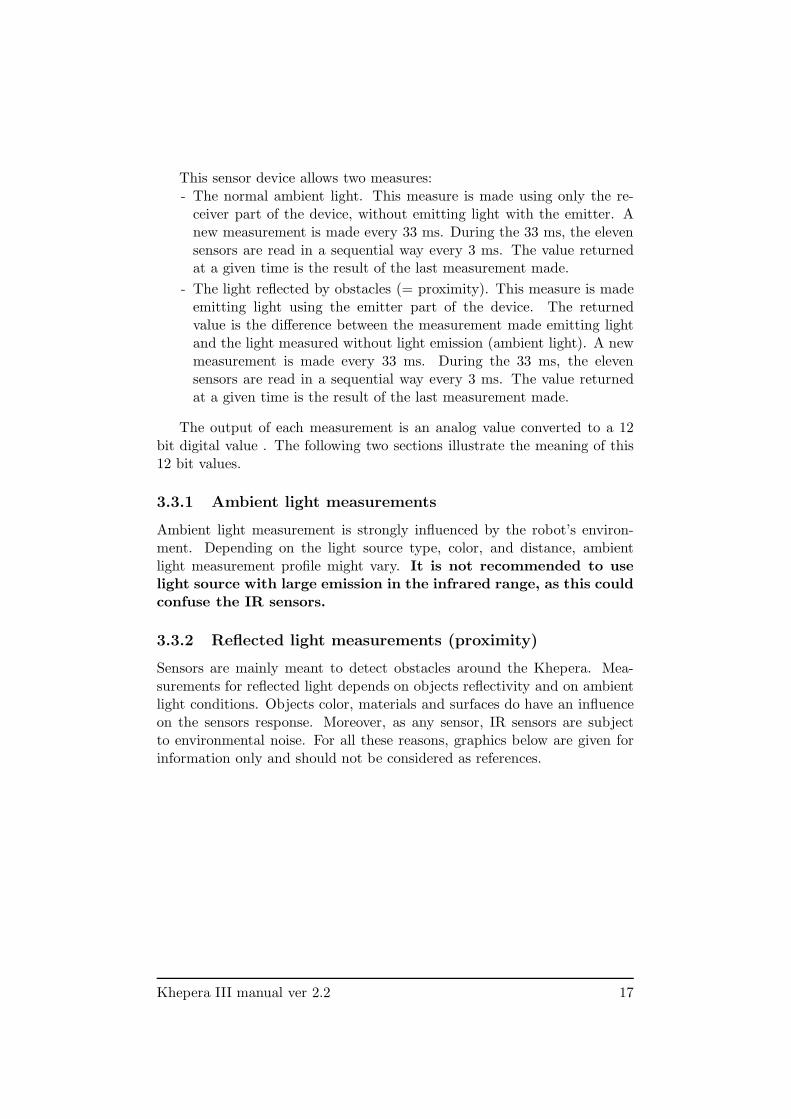
Sensors are mainly meant to detect obstacles around the Khepera. Mea-surements for reflected light depends on objects reflectivity and on ambientlight conditions. Objects color, materials and surfaces do have an influenceon the sensors response. Moreover, as any sensor, IR sensors are subjectto environmental noise. For all these reasons, graphics below are given forinformation only and should not be considered as references.
Khepera III manual ver 2.2 17
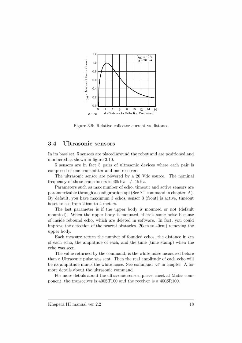
Figure 3.9: Relative collector current vs distance
3.4 Ultrasonic sensors
In its base set, 5 sensors are placed around the robot and are positioned andnumbered as shown in figure 3.10.
5 sensors are in fact 5 pairs of ultrasonic devices where each pair iscomposed of one transmitter and one receiver.
The ultrasonic sensor are powered by a 20 Vdc source. The nominalfrequency of these transducers is 40kHz +/- 1kHz.
Parameters such as max number of echo, timeout and active sensors areparametrizable through a configuration api (See ’C’ command in chapter A).By default, you have maximum 3 echos, sensor 3 (front) is active, timeoutis set to see from 20cm to 4 meters.
The last parameter is if the upper body is mounted or not (defaultmounted). When the upper body is mounted, there’s some noise becauseof inside rebound echo, which are deleted in software. In fact, you couldimprove the detection of the nearest obstacles (20cm to 40cm) removing theupper body.
Each measure return the number of founded echos, the distance in cmof each echo, the amplitude of each, and the time (time stamp) when theecho was seen.
The value returned by the command, is the white noise measured beforethan a Ultrasonic pulse was sent. Then the real amplitude of each echo willbe its amplitude minus the white noise. See command ’G’ in chapter A formore details about the ultrasonic command.
For more details about the ultrasonic sensor, please check at Midas com-ponent, the transceiver is 400ST100 and the receiver is a 400SR100.
Khepera III manual ver 2.2 18
Figure 3.10: Position of the 5 UltraSonic sensors.
3.5 Battery
The Khepera III is equipped with a battery pack composed of two Li-IonPolymer element. This provides a 7.4V volt battery with a 1400 mAHcapacity. Using its embedded power, the robot is able to run completelyautonomously during more than four hours, running with a basic configu-ration. When additional equipment are used, the autonomy is reduced asKhepera’s extensions as the KoreBotLE rely on Khepera’s batteries as apower source.
There is no specific power management system on the Khepera. Whenthe batteries voltage falls under 6V, the battery cut himself the power supplyto avoid a too important discharge of the cell. Users can implement theirown software power management system to handle KoreBotLE to shutdownproperly before this case happend. See command ’V’ in chapter A for moredetails about battery management.
3.6 Power Supply
If an external power source is required or during batteries charge, powercan be supplied through the power jack connector or through the micro-Match cable unroller connector. See section 4 for detailed description ofconnections.
Use only the power supply deliver by K-Team. If you want to
supply the Khepera III with another device, make sure that the
Voltage is +9V and that the power supply can deliver 2A.
SAFETY PRECAUTION: The power supply must be con-
nected to the wall socket after all other connections are already
made.
Khepera III manual ver 2.2 19
4 Connections
4.1 Configuration for batteries charge
To charge robot’s batteries, make sure the following are correct:
- The power supply shall be connected to the robot.
- Warning: the robot battery may be charged with the robot ON orOFF. Be attentive that when the robot is ON, the charging time willbe a bit longer.
- The power supply have to be connected on a wall plug.
There are three leds. A green led tells if the robot is powered or not.And two other leds are here if the robot is charging ( red led ON ) or if thecharge is complete ( green led ON ).
During the charge, the red led is switched ON and the green led isswitched OFF. The process is reversed at the end of the charging process.The charging time for an empty battery is about 180 minutes. At thismoment the power supply can be unplugged. When charging, the batterycan be as hot as 40 degrees.
K-Team S.A. 20

4.2 Configuration for Robot-Computer Communi-cation in standalone
This configuration allows communicating between the robot and a host com-puter through a serial link. The host computer is linked to the interfacemodule using a standard RS232 line, while the interface module convertsRS232 signal into a TTL level signal to communicate with the robot.
To use the standalone serial communication mode, please make sure thefollowing are correct:
- No KoreBotLE is connected on the Khepera III.
- The robot battery is charged that means the power led is switched on.
- The robot must be connected to a KoreConnect module using theserial cable
- The KoreConnect should be connected to the host computer using astandard RS232 cable. in this mode, the cable has to be connected onthe DB9 connector number 2 (see fig 4.1). You can easily purchasesuch a cable from your host computer dealer.
- Serial port configured as followed : 115200bps, 8 Data bits, 1 stop bit, no parity, no hardware control.
RS232 cables
KoreConnect
2
1
Figure 4.1: Connection when the robot is used without a KoreBotLE.
Khepera III manual ver 2.2 21
4.3 Configuration for Robot-Computer Communi-cation with KoreBotLE
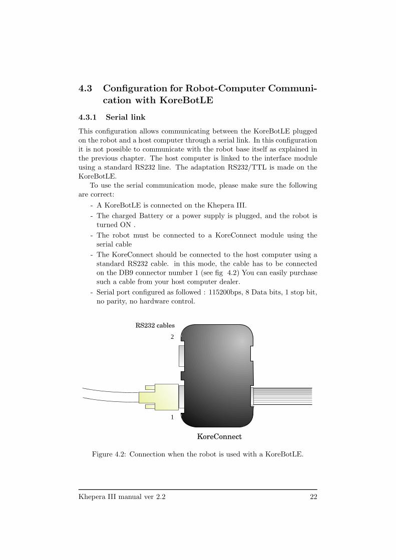
4.3.1 Serial link
This configuration allows communicating between the KoreBotLE pluggedon the robot and a host computer through a serial link. In this configurationit is not possible to communicate with the robot base itself as explained inthe previous chapter. The host computer is linked to the interface moduleusing a standard RS232 line. The adaptation RS232/TTL is made on theKoreBotLE.
To use the serial communication mode, please make sure the followingare correct:
- A KoreBotLE is connected on the Khepera III.
- The charged Battery or a power supply is plugged, and the robot isturned ON .
- The robot must be connected to a KoreConnect module using theserial cable
- The KoreConnect should be connected to the host computer using astandard RS232 cable. in this mode, the cable has to be connectedon the DB9 connector number 1 (see fig 4.2) You can easily purchasesuch a cable from your host computer dealer.
- Serial port configured as followed : 115200bps, 8 Data bits, 1 stop bit,no parity, no hardware control.
RS232 cables
KoreConnect
2
1
Figure 4.2: Connection when the robot is used with a KoreBotLE.
Khepera III manual ver 2.2 22
4.3.2 USB link
This configuration allows communicating between the KoreBotLE pluggedon the robot and a host computer through a USB link. There are two waysto connect the USB to the KoreBotLE. With a KoreConnect and standardUSB cable or with only a mini-USB cable.
For more information about the USB communication protocole with aKoreBotLE, please refer to the KoreBotLE documentation (found on website www.k-team.com).
To use the USB communication mode, please make sure the followingare correct:
- A KoreBotLE is plugged on the Khepera III.
- The charged battery or a power supply is plugged, and the robot isturned ON .
- The robot must be connected to a KoreConnect module and then aUSB cable or a mini-USB cable is plugged directly on the USB miniABconnector of the robot (see figure 3.1).
- The USB cable (standard or mini) should be connected to the hostcomputer. These two type of cable can be easily purchased from anycomputer dealer.
Khepera III manual ver 2.2 23
4.4 Bluetooth Communication
A Bluetooth device is mount on every KheperaIII with the firmware 2.0 orbigger. The device is a WT12 from BlueGiga, has the I-Wrap license andis configured by AT command. The device is completely configured for acable replacement for the KheperaIII. But can be used with the KoreBotLEtoo when plugged on the KheperaIII. Then the bluetooth connection will beavailable via the serial port /dev/tts/1 of the KoreBotLE. The configurationis the following:
- 115200bps data rate
- 8 data bits
- no parity
- one stop bit
- no hardware flow control
- connection securised (security code is: 0000)
4.4.1 Bluetooth communication with KheperaIII
Here a procedure as example to etablish a Bluetooth communication betweenKheperaIII and a PC, and how to validate the connection with a terminal(example for WinXp). No KoreBotLE must plugged on the KheperaIII forthis case.
- First connect your Bluetooth dongle to your PC (if necessary).
- Check if your system recognize your dongle and then install the driverIf you have Bluetooth integrated in your laptop, just activate it.
- Verify that your connection is securised and that a COM port isreserved for the Bluetooth serial communication (Menu: Bluetooth-Advanced Configuration-Client Application)
- Check if your KheperaIII is correctly powered (Led green ON)
- Start a device research ”View device in range”
- The KheperaIII must appear with a PDA logo and the name KHIIISerialNumber. The Serial Number is the same as the label on thebottom.
- Create a connection with the KheperaIII, your program will ask youfor a security code then enter 0000.
- Your program assign a COM port to your device.
- Open a terminal with the assigned COM port and the correct config-uration as above
- Try to read the IR sensor value (or another command see chapter A)to validate the communication
- Then you can use any other program which used a COM port (likeMatlab) to remote control your KheperaIII
Khepera III manual ver 2.2 24

4.4.2 Bluetooth communication with KoreBotLE
The procedure will be the same as above but with a KoreBotLE plugged onthe KheperaIII.
- Create a Bluetooth a connection with the KheperaIII as explainedabove
- To validate the communication, connect a KoreConnect to the Kore-BotLE (see section 4.3)
- Log on the KoreBotLE (login: root , password: rootme)
- open a minicom on the KoreBotLE (minicom -s /dev/tts/1)
- Configure your terminal as describe above and select the /dev/tts/1device.
- Now the KoreBotLE can send/received information to/from the PCvia Bluetooth.
4.4.3 Log On the KoreBotLE with a Bluetooth connection
There’s a way to use the /dev/tts/1 (Bluetooth serial Port) to log on theKoreBotLE. To do this, you need to modify the inittab file in the directory/etc of the KoreBotLE as following:
- Log on the KoreBotLE with a KoreConnect (login: root , password:rootme)
- Open the /etc/initab files (vi /etc/inittab)
- In the end of the files, you will see this line :T0:23:respawn:/sbin/getty-L ttyC0 115200 vt100
- Modify it to: T1:23:respawn:/sbin/getty -L /dev/tts/1 115200 vt100
- Save and close the file. Then in the next restart, you will be able tolog on your KoreBotLE with Bluetooth.
Khepera III manual ver 2.2 25
5 Serial Communication Mode
5.1 Testing the primary serial link
Before any further operations, the serial link between the host computer andthe robot should be tested. Please read the following instructions to testthe serial communication mode:
- Make sure all connections are correct (see chapter 4 for details).
- The robot should be placed on a flat and safe surface. The batteryswitch must be OFF.
- A terminal emulator should be running on the host computer. Makesure the terminal is connected to the correct serial port. The termi-
nal configuration must be set to 115200 Baud, 8 bit, 1 start
bit, 1 stop bit, no parity and no hardware control.
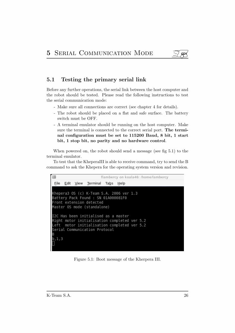
When powered on, the robot should send a message (see fig 5.1) to theterminal emulator.
To test that the KheperaIII is able to receive command, try to send the Bcommand to ask the Khepera for the operating system version and revision.
Figure 5.1: Boot message of the Kherpera III.
K-Team S.A. 26
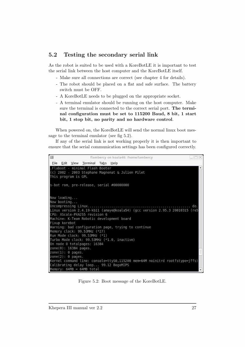
5.2 Testing the secondary serial link
As the robot is suited to be used with a KoreBotLE it is important to testthe serial link between the host computer and the KoreBotLE itself.
- Make sure all connections are correct (see chapter 4 for details).
- The robot should be placed on a flat and safe surface. The batteryswitch must be OFF.
- A KoreBotLE needs to be plugged on the appropriate socket.
- A terminal emulator should be running on the host computer. Makesure the terminal is connected to the correct serial port. The termi-
nal configuration must be set to 115200 Baud, 8 bit, 1 start
bit, 1 stop bit, no parity and no hardware control.
When powered on, the KoreBotLE will send the normal linux boot mes-sage to the terminal emulator (see fig 5.2).
If any of the serial link is not working properly it is then important toensure that the serial communication settings has been configured correctly.
Figure 5.2: Boot message of the KoreBotLE.
Khepera III manual ver 2.2 27
5.3 Serial communication protocol
When the robot is used as standalone ( without a KoreBotLE ), the serialcommunication protocol is designed to control all Khepera’s functions usinga RS232 serial line. The serial line configuration (baudrate as well as data,start, stop and parity bits) for the host computer must match the robot’sconfiguration.
The host computer and the Khepera robot are communicating withASCII messages. Each single interaction is composed by:
- A command, beginning with one ASCII capital letters and followed,if necessary, by numerical or literal parameters separated by a commaand terminated by a carriage return or a line feed, sent by the hostcomputer to the Khepera robot.
- A response, beginning with the same one ASCII letters of the com-mand but in lower-case and followed, if necessary, by numerical or lit-eral parameters separated by a comma and terminated by a carriagereturn and a line feed, sent by the Khepera to the host computer.
During the entire communication, the host computer is acting as a masterand the Khepera as slave. All communications are initiated by the master.
Two different types of interactions are possible. The first set of inter-actions is used to set up the robot configuration from the host computer(set up serial line, changing controllers configuration,...), the second set ofinteractions is used to control the robot (controlling motors, reading sensorsvalue,...).
A set of commands is available as detailed in appendix.
5.3.1 Testing a simple interaction
Testing some basic commands is the best method to understand the serialprotocol and tools available on the Khepera. Using a properly configuredserial link between the robot and a computer, please follow the instructionsbellow:
- Type the capital letter B followed by a carriage return or a line feed.
- The robot must respond with b followed by an indication of the versionof software running on the robot and terminated by a line feed.
- Type the capital letter N followed by a carriage return or a line feed.
- The robot must respond with n followed by 11 numbers separated bya comma and terminated by a line feed. These numbers are the valuesof the robot proximity sensors presented in section 3.1.6.
- Retry the same command (N) putting some obstacles in front of therobot. The response must change.
- Type the protocol command D,l10000,l-10000 followed by a carriagereturn or a line feed.
Khepera III manual ver 2.2 28

- The robot must start turning on place and respond with d and a linefeed.
- To stop the robot type the protocol command D,l0,l0 followed by acarriage return or a line feed.
- Try other commands following the description given in Appendix A.
Khepera III manual ver 2.2 29
6 KoreBotLE programming
This section explain how to write a simple program for the KoreBotLE tocontrol the Khepera III base. The Khepera III will act as peripheral of theKoreBotLE.
Please refer to the KoreBotLE user manual (found on www.k-team.com)for further details on KoreBotLE programming. This document only pro-vides a basic example of program compilation and execution.
The first simple executable for KoreBotLE/Khepera III will be builtassuming:
- A working arm-linux toolchain is installed on your host computer.
- The NFS link is active and a shared directory (mySharedDirectory) ismounted on /mnt/nfs.
A source file should be first created and edited with a very simple Cprogram such as the following. People familiar with the KoreMotor willnotice that the code is quite similar. The controlers have been embedded inthe robot but act as two I2C slaves.
/* kh3test.c */
#include <korebot/korebot.h>
static knet_dev_t * mot1;
static knet_dev_t * mot2;
int main()
{
kh3_init();
/* open various socket and store the handle in their respective pointers */
dsPic = knet_open( "Khepera3:dsPic" , KNET_BUS_I2C , 0 , NULL );
mot1 = knet_open( "Khepera3:mot1" , KNET_BUS_I2C , 0 , NULL );
mot2 = knet_open( "Khepera3:mot2" , KNET_BUS_I2C , 0 , NULL );
/* initialize the motor controler 1 */
kmot_SetMode( mot1 , kMotModeIdle );
kmot_SetSampleTime( mot1 , 1550 );
kmot_SetMargin( mot1 , 6 );
kmot_SetOptions( mot1 , 0x0 , kMotSWOptWindup | kMotSWOptStopMotorBlk
| kMotSWOptDirectionInv );
K-Team S.A. 30
kmot_ResetError( mot1 );
kmot_SetBlockedTime( mot1 , 10);
kmot_ConfigurePID( mot1 , kMotRegSpeed , 400 , 0 , 10 );
kmot_ConfigurePID( mot1 ,kMotRegPos,620,3,10);
kmot_SetSpeedProfile(mot1 ,30,3);
/* initialize the motor controler 2 */
kmot_SetMode( mot2 , kMotModeIdle );
kmot_SetSampleTime( mot2 , 1550 );
kmot_SetMargin( mot2 , 6 );
kmot_SetOptions( mot2 , 0x0 , kMotSWOptWindup | kMotSWOptStopMotorBlk );
kmot_ResetError( mot2 );
kmot_SetBlockedTime( mot2 , 10);
kmot_ConfigurePID( mot2 , kMotRegSpeed , 400 , 0 , 10 );
kmot_ConfigurePID( mot2 ,kMotRegPos,620,3,10);
kmot_SetSpeedProfile(mot2 ,30,3);
/* For ever loop */
while(1)
{
/* Wait 5 seconds */
sleep(5);
/* Tell to the motor controller to move the Khepera III forward */
kmot_SetPoint( mot1 , kMotRegSpeed , -motspeed );
kmot_SetPoint( mot2 , kMotRegSpeed , motspeed );
/* Wait 5 seconds */
sleep(5);
/* Tell to the motor controller to stop the Khepera III */
kmot_SetPoint( mot1 , kMotRegSpeed , 0 );
kmot_SetPoint( mot2 , kMotRegSpeed , 0 );
}
}
This source code can be cross-compiled using arm-linux-gcc which sup-ports most standard gcc options:
arm-linux-gcc kh3test.c -o k3test
An kh3test executable file should be created, that can be executed onthe KoreBotLE, or eventually another arm-linux machine.
Khepera III manual ver 2.2 31

To execute the program, simply copy kh3test to the nfs shared direc-tory, then execute it from a KoreBotLE terminal. If the shared directory ismounted on the default /mnt/nfs, first change working directory:
cd /mnt/nfs
Then check that kh3test is present:
ls -l
And execute it:
./k3test
Khepera III manual ver 2.2 32
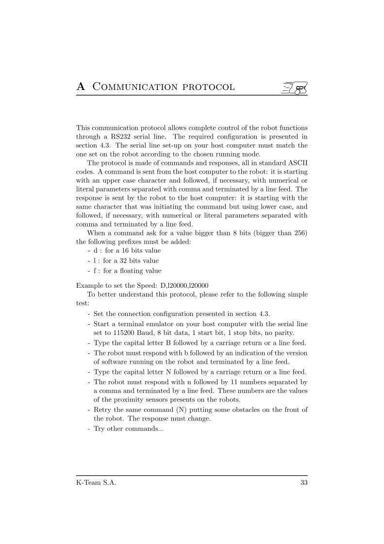
A Communication protocol
This communication protocol allows complete control of the robot functionsthrough a RS232 serial line. The required configuration is presented insection 4.3. The serial line set-up on your host computer must match theone set on the robot according to the chosen running mode.
The protocol is made of commands and responses, all in standard ASCIIcodes. A command is sent from the host computer to the robot: it is startingwith an upper case character and followed, if necessary, with numerical orliteral parameters separated with comma and terminated by a line feed. Theresponse is sent by the robot to the host computer: it is starting with thesame character that was initiating the command but using lower case, andfollowed, if necessary, with numerical or literal parameters separated withcomma and terminated by a line feed.
When a command ask for a value bigger than 8 bits (bigger than 256)the following prefixes must be added:
- d : for a 16 bits value
- l : for a 32 bits value
- f : for a floating value
Example to set the Speed: D,l20000,l20000To better understand this protocol, please refer to the following simple
test:
- Set the connection configuration presented in section 4.3.
- Start a terminal emulator on your host computer with the serial lineset to 115200 Baud, 8 bit data, 1 start bit, 1 stop bits, no parity.
- Type the capital letter B followed by a carriage return or a line feed.
- The robot must respond with b followed by an indication of the versionof software running on the robot and terminated by a line feed.
- Type the capital letter N followed by a carriage return or a line feed.
- The robot must respond with n followed by 11 numbers separated bya comma and terminated by a line feed. These numbers are the valuesof the proximity sensors presents on the robots.
- Retry the same command (N) putting some obstacles on the front ofthe robot. The response must change.
- Try other commands...
K-Team S.A. 33
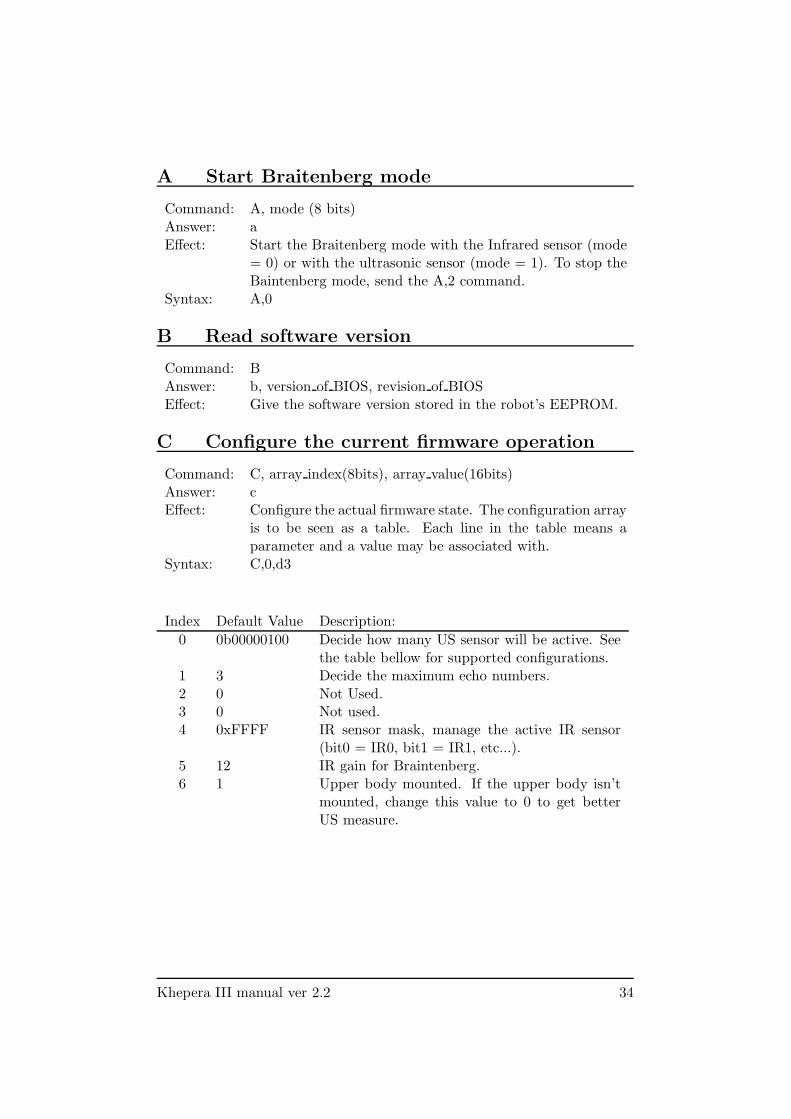
A Start Braitenberg mode
Command: A, mode (8 bits)Answer: aEffect: Start the Braitenberg mode with the Infrared sensor (mode
= 0) or with the ultrasonic sensor (mode = 1). To stop theBaintenberg mode, send the A,2 command.
Syntax: A,0
B Read software version
Command: BAnswer: b, version of BIOS, revision of BIOSEffect: Give the software version stored in the robot’s EEPROM.
C Configure the current firmware operation
Command: C, array index(8bits), array value(16bits)Answer: cEffect: Configure the actual firmware state. The configuration array
is to be seen as a table. Each line in the table means aparameter and a value may be associated with.
Syntax: C,0,d3
Index Default Value Description:
0 0b00000100 Decide how many US sensor will be active. Seethe table bellow for supported configurations.
1 3 Decide the maximum echo numbers.2 0 Not Used.3 0 Not used.4 0xFFFF IR sensor mask, manage the active IR sensor
(bit0 = IR0, bit1 = IR1, etc...).5 12 IR gain for Braintenberg.6 1 Upper body mounted. If the upper body isn’t
mounted, change this value to 0 to get betterUS measure.
Khepera III manual ver 2.2 34

The supported US sensors configuration are listed in the following table.
Mask Binary Decimal Description:
NONE 0b00000000 0 None of the US sensor.US1ONLY 0b00000001 1 Only the US sensor 1.US2ONLY 0b00000010 2 Only the US sensor 2.US3ONLY 0b00000100 4 Only the US sensor 3.US4ONLY 0b00001000 8 Only the US sensor 4.US5ONLY 0b00010000 16 Only the US sensor 5.US1TO2 0b00000011 3 US sensor 1 to 2.US2TO3 0b00000110 6 US sensor 2 to 3.US3TO4 0b00001100 12 US sensor 3 to 4.US4TO5 0b00011000 24 US sensor 4 to 5.US1TO3 0b00000111 7 US sensor 1 to 3.US2TO4 0b00001110 14 US sensor 2 to 4.US3TO5 0b00011100 28 US sensor 3 to 5.US1TO4 0b00001111 15 US sensor 1 to 4.US2TO5 0b00011110 30 US sensor 2 to 5.USALL 0b00011111 31 All US sensors.
D Set speed
Command: D, speed motor left (32bits), speed motor right (32bits)Answer: dEffect: Set the speed of the two motors. See in section 3.2.1 to
calculate the equivalent Speed.Syntax: D,l20000,l20000
E Read speed
Command: EAnswer: e, speed motor left, speed motor rightEffect: Read the instantaneous speed of the two motors. See in
section 3.2.1 to calculate the equivalent Speed.Example: e,20000,20000
Khepera III manual ver 2.2 35
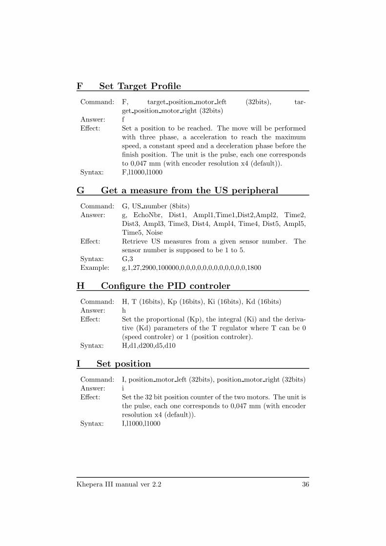
F Set Target Profile
Command: F, target position motor left (32bits), tar-get position motor right (32bits)
Answer: fEffect: Set a position to be reached. The move will be performed
with three phase, a acceleration to reach the maximumspeed, a constant speed and a deceleration phase before thefinish position. The unit is the pulse, each one correspondsto 0,047 mm (with encoder resolution x4 (default)).
Syntax: F,l1000,l1000
G Get a measure from the US peripheral
Command: G, US number (8bits)Answer: g, EchoNbr, Dist1, Ampl1,Time1,Dist2,Ampl2, Time2,
Dist3, Ampl3, Time3, Dist4, Ampl4, Time4, Dist5, Ampl5,Time5, Noise
Effect: Retrieve US measures from a given sensor number. Thesensor number is supposed to be 1 to 5.
Syntax: G,3Example: g,1,27,2900,100000,0,0,0,0,0,0,0,0,0,0,0,0,1800
H Configure the PID controler
Command: H, T (16bits), Kp (16bits), Ki (16bits), Kd (16bits)Answer: hEffect: Set the proportional (Kp), the integral (Ki) and the deriva-
tive (Kd) parameters of the T regulator where T can be 0(speed controler) or 1 (position controler).
Syntax: H,d1,d200,d5,d10
I Set position
Command: I, position motor left (32bits), position motor right (32bits)Answer: iEffect: Set the 32 bit position counter of the two motors. The unit is
the pulse, each one corresponds to 0,047 mm (with encoderresolution x4 (default)).
Syntax: I,l1000,l1000
Khepera III manual ver 2.2 36

J Configure the speed profile controller
Command: J, max speed (16bits), acceleration (8bits)Answer: jEffect: Set the speed and the acceleration for the trapezoidal speed
shape of the position controller. The max speed parameterindicates the maximal speed reached during the displace-ment. See section 3.2.1 for more details. At the reset, theseparameters are set to standard values: max speed to 20000,acc to 64.
Syntax: J,d15000,10
K Set Programmable Led
Command: K, LED (8bits), State (8bits)Answer: kEffect: Set the state of the two Programmable Leds ( see section
3.1.3, Led 5 & 6). LED select which one must be set (0 =led 5, 1 = Led 6).State select the operation (0 = OFF, 1 = ON, 2 = Changestate).
Syntax: K,0,1
L Set speed open loop
Command: L, speed motor left (32bits), speed motor right (32bits)Answer: lEffect: Set the speed of the two motors without a PID controller.
Where a value of 1023 correspond to PWM of 100%.Syntax: L,l500,l500
M Init Motors
Command: MAnswer: mEffect: Initialise or reset the motor controllers. Must be used if an
error like motor blocked or current limit occured
Khepera III manual ver 2.2 37
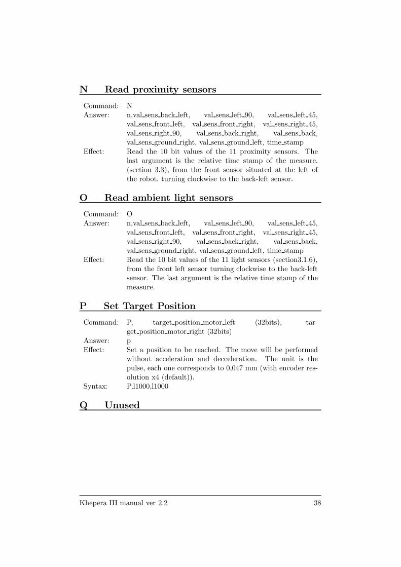
N Read proximity sensors
Command: NAnswer: n,val sens back left, val sens left 90, val sens left 45,
val sens front left, val sens front right, val sens right 45,val sens right 90, val sens back right, val sens back,val sens ground right, val sens ground left, time stamp
Effect: Read the 10 bit values of the 11 proximity sensors. Thelast argument is the relative time stamp of the measure.(section 3.3), from the front sensor situated at the left ofthe robot, turning clockwise to the back-left sensor.
O Read ambient light sensors
Command: OAnswer: n,val sens back left, val sens left 90, val sens left 45,
val sens front left, val sens front right, val sens right 45,val sens right 90, val sens back right, val sens back,val sens ground right, val sens ground left, time stamp
Effect: Read the 10 bit values of the 11 light sensors (section3.1.6),from the front left sensor turning clockwise to the back-leftsensor. The last argument is the relative time stamp of themeasure.
P Set Target Position
Command: P, target position motor left (32bits), tar-get position motor right (32bits)
Answer: pEffect: Set a position to be reached. The move will be performed
without acceleration and decceleration. The unit is thepulse, each one corresponds to 0,047 mm (with encoder res-olution x4 (default)).
Syntax: P,l1000,l1000
Q Unused
Khepera III manual ver 2.2 38

R Read position
Command: RAnswer: r, position motor left, position motor rightEffect: Read the 32 bit position counter of the two motors. The
unit is the pulse, each one corresponds to 0,047 mm (withencoder resolution x4 (default)).
S Unused
T Unused
U Enter the serial boot loader mode
Command: UAnswer: uEffect: Switch to the firmware upgrade mode. Be careful, not to
upload a bad hex file into the dsPic memory space. If thedsPic memory is corrupted, an external programmer will berequired to reflash the memory.Do not turn off or reset the KheperaIII when the uploadermode running. This will corrupt the dsPic memory. If youhave run the mode by mistake, wait until the timeout occurs(5-7 seconds).
V Get Battery State
Command: V, index (8bits)Answer: v, battery measure unit, battery measure decimalEffect: 0: Read the voltage of the battery (Units: 1V , 0.1mV) .
1: Read the current of the battery (Units: 1A, 0.1mA).2: Read the battery Average Current (Units: 1A, 0.1mA).3: Read the battery Absolute Remaining Capacity (Units:1Ah).
4: Read the Temperature of the battery (Units: 1 C, 0.1)́.5: Read the battery Relative Remaining Capacity (Units:%).
W Unused
Khepera III manual ver 2.2 39
X Unused
Y Unused
Z Zero the relative time stamp
Command: ZAnswer: zEffect: Reset the relative time counter.
Khepera III manual ver 2.2 40


![SECURITIES AND EXCHANGE COMMISSION ......RIW KH6 HFUHWDU\ DQGDWW KH& RPPLVVLRQ V3 XEOLF5 HIHUHQFH5 RRP . II. Self -5HJXODWRU\2UJDQL]DWLRQ V6 WDWHPHQWRIW KH3 XUSRVHR I DQG6WDWXWRU\%DVLVI](https://img.pdfslide.us/doc/110x75/61179caec3e32c37624fcff5/securities-and-exchange-commission-riw-kh6-hfuhwdu-dqgdww-kh-rpplvvlrq.jpg)


![Overcast - ai.vub.ac.be · Decision T ree Learning [read Chapter 3] [recommended exercises 3.1, 3.4] Decision tree represen tation ID3 learning algorithm En trop y, Information gain](https://img.pdfslide.us/doc/110x75/5ec67c16ae6d260984337f4a/overcast-aivubacbe-decision-t-ree-learning-read-chapter-3-recommended-exercises.jpg)