Embed Size (px)
Citation preview
University of Pennsylvania University of Pennsylvania
ScholarlyCommons ScholarlyCommons
Technical Reports (CIS) Department of Computer & Information Science
October 1990
TRACS: The Hardware and Software Architecture of a New Two TRACS: The Hardware and Software Architecture of a New Two
Robotic Arm Coordination System Robotic Arm Coordination System
Eric Paljug University of Pennsylvania
Xiaoping Yun University of Pennsylvania
Filip Fuma University of Pennsylvania
Follow this and additional works at: https://repository.upenn.edu/cis_reports
Recommended Citation Recommended Citation Eric Paljug, Xiaoping Yun, and Filip Fuma, "TRACS: The Hardware and Software Architecture of a New Two Robotic Arm Coordination System", . October 1990.
University of Pennsylvania Department of Computer and Information Science Technical Report No. MS-CIS-90-70.
This paper is posted at ScholarlyCommons. https://repository.upenn.edu/cis_reports/559 For more information, please contact [email protected].
TRACS: The Hardware and Software Architecture of a New Two Robotic Arm TRACS: The Hardware and Software Architecture of a New Two Robotic Arm Coordination System Coordination System
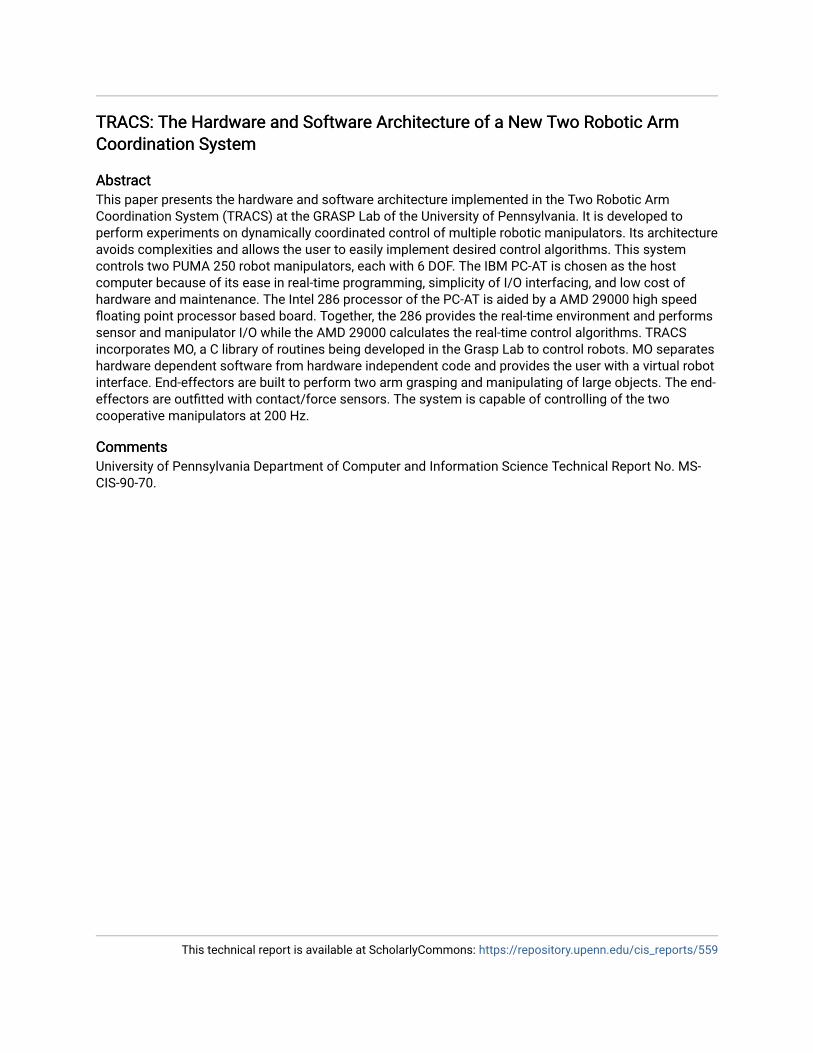
Abstract Abstract This paper presents the hardware and software architecture implemented in the Two Robotic Arm Coordination System (TRACS) at the GRASP Lab of the University of Pennsylvania. It is developed to perform experiments on dynamically coordinated control of multiple robotic manipulators. Its architecture avoids complexities and allows the user to easily implement desired control algorithms. This system controls two PUMA 250 robot manipulators, each with 6 DOF. The IBM PC-AT is chosen as the host computer because of its ease in real-time programming, simplicity of I/O interfacing, and low cost of hardware and maintenance. The Intel 286 processor of the PC-AT is aided by a AMD 29000 high speed floating point processor based board. Together, the 286 provides the real-time environment and performs sensor and manipulator I/O while the AMD 29000 calculates the real-time control algorithms. TRACS incorporates MO, a C library of routines being developed in the Grasp Lab to control robots. MO separates hardware dependent software from hardware independent code and provides the user with a virtual robot interface. End-effectors are built to perform two arm grasping and manipulating of large objects. The end-effectors are outfitted with contact/force sensors. The system is capable of controlling of the two cooperative manipulators at 200 Hz.
Comments Comments University of Pennsylvania Department of Computer and Information Science Technical Report No. MS-CIS-90-70.
This technical report is available at ScholarlyCommons: https://repository.upenn.edu/cis_reports/559
TRACS: The Hardware And Software Architecture Of A New Two Robotic Arm Coordination System
MS-CIS-90-70 GRASP LAB 236
Eric Paljug Xiaoping Yun
Filip Fuma
Department of Computer and Information Science School of Engineering and Applied Science
University of Pennsylvania Philadelphia, PA 19104-6389
October 1990
TRACS: The Hardware and Software Architecture of a New Two Robotic Arm Coordination System
Eric Paljug Xiaoping Yun
Filip Fuma
GRASP Laboratory University of Pennsylvania
3401 Walnut Street, Room 301C Philadelphia, PA 19 104-6228
ABSTRACT
This paper presents the hardware and software architecture implemented in the Two Robotic Arm Coordination System (TRACS) at the GRASP Lab of the University of Pennsylvania. It is developed to perform experiments on dynamically coordinated control of multiple robotic manipu- lators. Its architecture avoids complexities and allows the user to easily implement desired control algorithms. This system controls two PUMA 250 robot manipulators, each with 6 DOF. The IBM PC-AT is chosen as the host computer because of its ease in real-time programming, simplicity of I/O interfacing, and low cost of hardware and maintenance. The Intel 286 processor of the PC-AT is aided by a AMD 29000 high speed floating point processor based board. Together, the 286 provides the real-time environment and performs sensor and manipulator I/O while the AMD 29000 calculates the real-time control algorithms. TRACS incorporates MO, a C library of routines being developed in the Grasp Lab to control robots. MO separates hardware dependent software from hardware independent code and provides the user with a virtual robot interface. End-effectors are built to perform two arm grasping and manipulating of large objects. The end-effectors are outfitted with contact/force sensors. The system is capable of controlling of the two cooperative manipulators at 200 Hz.
1 Introduction
Two arm and multi-arm robot control is an interesting and developing area of robotics research [lo, 15, 18, 221, yet few experimental results have been published [19, 131. An effort has been made at the Grasp to develop an experimental system for implementation of coordinated control of two manipulators. This paper describes the development of the controller architecture for this system.
The design process begins by identifying the basic requirements and desirable features of a system that can perform two arm coordinated experiments. As with many robotics research labs, the Grasp Lab has had a variety of robot controller architectures. Along with the basic requirements, the experience in developing and using these controller architectures influences the design of TRACS. As with any engineering design problem, there will be tradeoffs. These are investigated and resolved by following the basic design specification. While this system is designed for two-arm coordinated manipulation, its architecture should prove useful for general applications. The design can be implementation in many ways. The realization described in this paper meets the design specification and is itself evolving. The ability to effect changes in the actual system without having to redesign a new controller is an important feature of this design,
This paper describes the development of TRACS as follows: Section two briefly outlines the controller architectures the Grasp lab is or has employed and other published controllers. Section three contains the system specification. Section four will describe the actual imple- mentation. Section five highlights the experiments being conducted with this system. The final section provides a summary of the paper.
2 Overview of Controller Architectures
The Grasp lab has experience with a variety of robot controllers. Two Unimation PUMA 560 6 DOF manipulators are each controlled by a MicroVax I1 under ULTRIX using the Robot Control Interface (RCI) and Robot Control C Library (RCCL) [14]. The RCI pro- gram provides the real-time interrupt kernel device driver in Unix and does the low level communication between the the MicroVax and the Unimate LSI-11 supervisor processor. The RCCL provides a software platform to develop robot control programs. Together, RCI and RCCL provide an alternative to the VAL I1 programming language originally supplied with the PUMA robot. For both VAL and RCCL, position control is perform by the Unimate joint controller boards.
The RFMS [21] system was developed to implement a distributed multi-processor (MIMD) controller architecture. The RFMS system ran parallel algorithms on iSBC 86/30 computer boards to control a PUMA 250 robot arm at the low level and used a VAX 11/785 under ULTRIX to give high level force and motion instructions. The two levels communicated through ethernet. The low level inputs and outputs are the encoder and actuator signals, thus the system completely controls the arm and does not make use of the original Unimate controller beyond its power supplies and amplifiers.
The MMCS [7] system was developed to control a PUMA 250 robot from a Sun work- station running Unix. A real-time interrupt kernel device driver was written into the Unix operating system. The both high and low level calculations are done on the workstation's single processor. Custom built MMCS boards interface the robot actuators and encoders signals to the workstation. As with RFMS, this system does not make use of the Unimate controller beyond its power amplifiers. Unlike the RFMS, this system has a single processor which simplifies software development and the workstation provides a better programming environment.
Later the JIFFE board [4], a very high speed scalar coprocessor, was added to the Sun workst ation of MMCS. JIFFE enables the system to perform complex control algorithms at a rate of 1 KHz and removes the need for a real-time interrupt kernel device driver in the Unix operating system.
Other researchers have also developed robot controllers to conduct experiments. A few representative ones are described below. Bihn and Hsia [6] developed a universal robot controller based on Intel System 310 and Multibus technology and running Xenix. They choose the Xenix operating system for its software development environment. Because it is not a real-time operating system, a kernel level real-time interrupt driver is added to the system. The control software is physically linked to this driver.
Carnegie-Mellon University has developed CHIMERA for control of the Reconfigurable Modular Manipulator System [17]. This system employs a Sun 3 workstation as the host computer and one or more Ironics 68020 CPU boards to perform the real-time control. The workstation under Unix provides a powerful software development environment. Both the Sun and Ironics use the same processor family. Real-time programs are run as concurrent processes from the real-time executive kernel.
MIT has developed CONDOR to control the Utah-MIT hand [16]. The system hardware is similar to CMU's CHIMERA, however the Ironics boards each run a single process and communication between processors is done through messages.
IBM has developed SPARTA to control robots [12]. SPARTA is composed of an IBM VM/CMS mainframe for program development, a IBM-PC for the user interface and real- time support, and multiple IBM Hermes signal processors for real-time calculations and 110.
AT&T has continued development of a robot controller based on multiple JIFFE scalar supercomputers [5]. This system VME based and has complementary boards to provide the robot and vision interface. The system is able to perform complex control algorithms involving many actuators at sample rates of 1 KHz.
There exist systems that use other real-time environments such as VxWorks, VRTX and Lynx.
3 System Specification
TRACS is intend to perform research experiments involving the control of two coordinated robot arms. As such, the basic system specifications are identified:
Ability to implement a variety of robot control algorithms, from kinematic based po- sition control to dynamic based computed torque control to new techniques in coordi- nated control developed by ongoing research. Underlying this ability are the following requirements or goals:
- Adequate sampling rate. The structural resonant frequency of many robotic arms fall into the range of 5 to 25 Hz [8]. The control signal bandwidth must avoid exiting structural resonances. It is not uncommon for an adequate sample rate of a digital controller to be 4 to 20 times the system's closed loop bandwidth [9]. Thus a sampling rate lower bound of a 200 Hz is chosen.
- High speed floating point processing capability.
- Complete control of the actuators by outputting the servo control signal directly to the actuators, and eliminating the need for any other low level servo loop control.
- Feedback of end-effector forces will be required for many control strategies.
Tightly coupled control with minimum communication delays between robots.
Simple design structure to facilitate real-time control, software development and exe- cution, and hardware additions/reconfigurations.
Low initial, maintenance and support costs.
These system specifications lead to software and hardware design tradeoffs. Many of the systems to date have adopted Unix-like operating systems as their basis because of the powerfu.1 software development tools, but at the cost of adding a real-time interrupt device driver to the system kernel. The alternative is to use a real-time system and to create a useful software development environment within it. Important characteristics of this environment should include the ability to implement a new control algorithm without explicit knowledge of the entire underlying system, a satisfactory user interface, and development tools.
Multiprocessors have been employed to increase the computational ability of systems at the expense of a complicated programming and processor coordination. Single threaded architectures are becoming more reasonable as technology has enabled faster single processors to be produced.
Elaborate hardware and software systems are common in many controller architectures, but these come at a high price, both initially and through maintenance and support. Where elaborate systems are not a necessity, a simple solution is pursued. In this regard, the use of off-the-shelf technology is also desirable. This allows concentration of effort toward research rather than development.
4 System Realization This section details the GRASP Lab's realization of a coordinated two arm controller as specified in the previous section.
4.1 Hardware
An IBM PC-AT (compatible) was chosen as the host computer platform. The PC-AT with MS-DOS is easily configurable to a real-time system. The PC-AT, being a very common plat- form, has one of the largest variety of inexpensive, off-the-shelf interfaces and development tools. This significantly reduces the need for custom hardware and software.
To meet the speed and throughput requirements of dynamic control algorithms, the PC- AT is out-fitted with a coprocessor board. This is an AMD 29000 based high speed floating point coprocessor board by YARC System Corporation [I]. The board interfaces to the PC bus through shared memory and 110 space. The user can program the board entirely in C. The manufacturer claims the board can achieve sustained execution rates of 17 MIPS. It rates the standard whetstone benchmark at 5.365 Mwhetstones/sec which according to [4] is 5 times greater than a Sun 31260 performance and a factor of about 5 less than JIFFE's 24.5 Mwhetstones/sec. Nevertheless, an offline benchmark which consisted of calculating both PUMA 250's actual forward kinematics, inverse kinematics, Jacobian, Inverse Jacobian, and gravity compensation runs at 2873 ms. A routine representing the dynamic calculations for a PUMA is added to the above benchmark to yield a benchmark of 1.6164 ms. If all these calculations are incorporated into the control law, the system sampling rate is constrained below 600 Hz. In the event that future algorithms will require greater throughput, an additional AMD 29000 board can be added to the system.
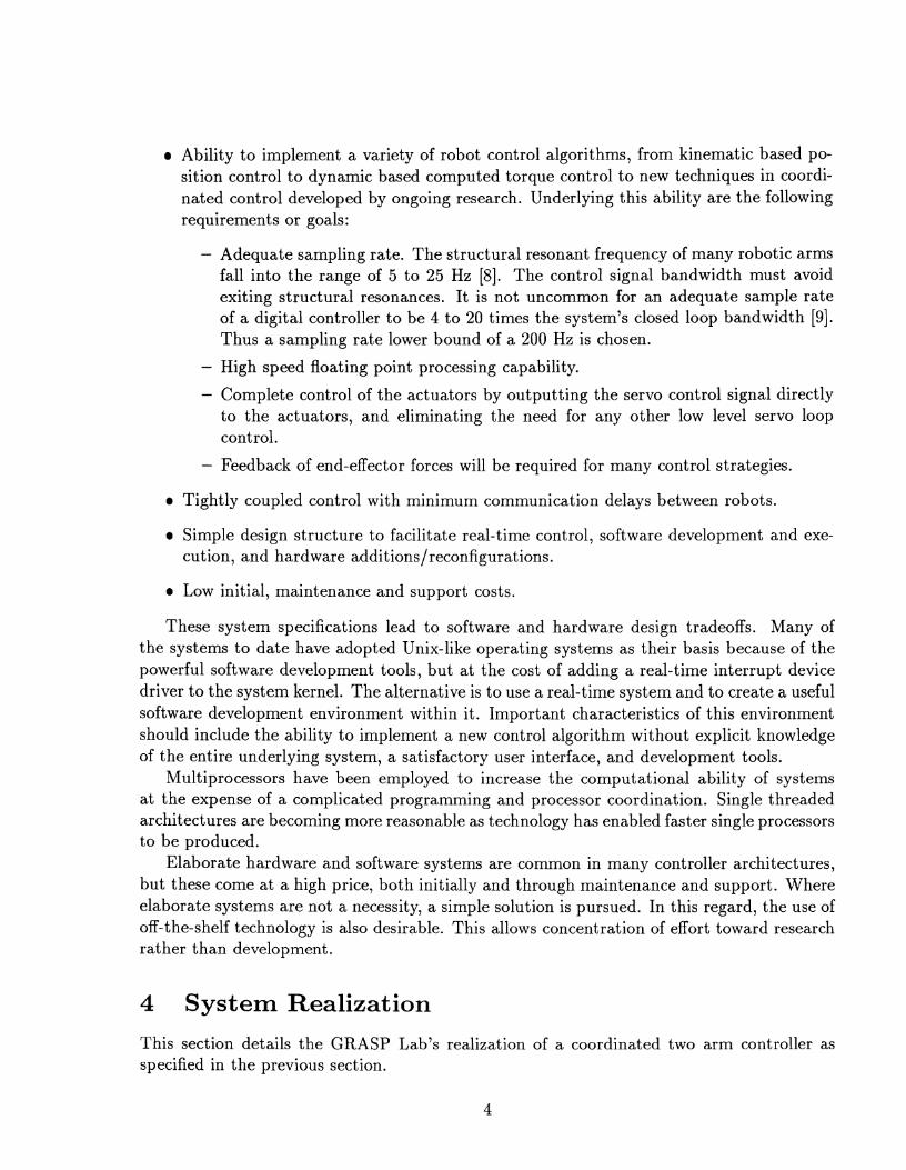
The hardware architecture is shown in Fig. 1. This system controls two PUMA 250 robots, 12 actuators in all. It uses the PUMA'S original amplifiers and joint controller boards. These perform incremental encoder interface and digital-to-analog (DAC) conversion functions. The PC-AT communicates to the joint boards through a parallel interface. The PC-AT reads the joint angles (encoder values) and writes the actuator currents (DAC values). The parallel communication produces a delay on the PC-AT processor of about 1.2 ms to read in all 12 encoders and another 1.2 ms to write out all 12 DACs. The PC-AT'S 80286 and the AMD 29000 operate concurrently, overlapping the communication delay with the computation of the control algorithm. Thus the sampling period is not the sum of the communication delay and the control algorithm compute time (see Section 4.2). It is possible to reduce the communication delay to about 180 microseconds for 12 encoder reads and 12 DAC writes through the use of interface boards located directly on the PC 110 bus.
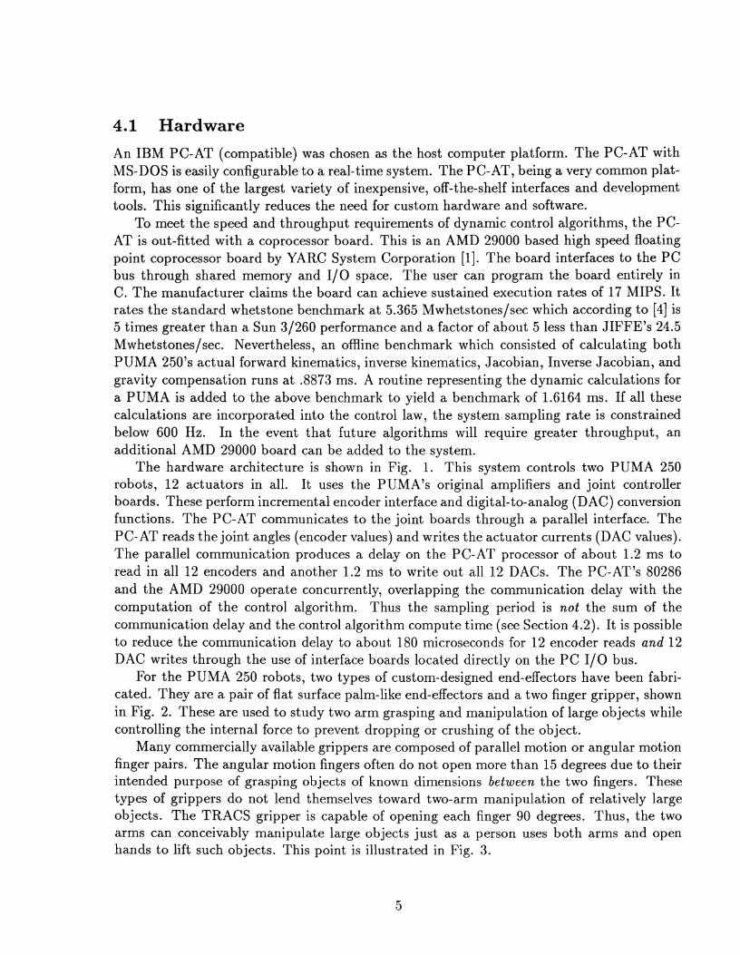
For the PUMA 250 robots, two types of custom-designed end-effectors have been fabri- cated. They are a pair of flat surface palm-like end-effectors and a two finger gripper, shown in Fig. 2. These are used to study two arm grasping and manipulation of large objects while controlling the internal force to prevent dropping or crushing of the object.
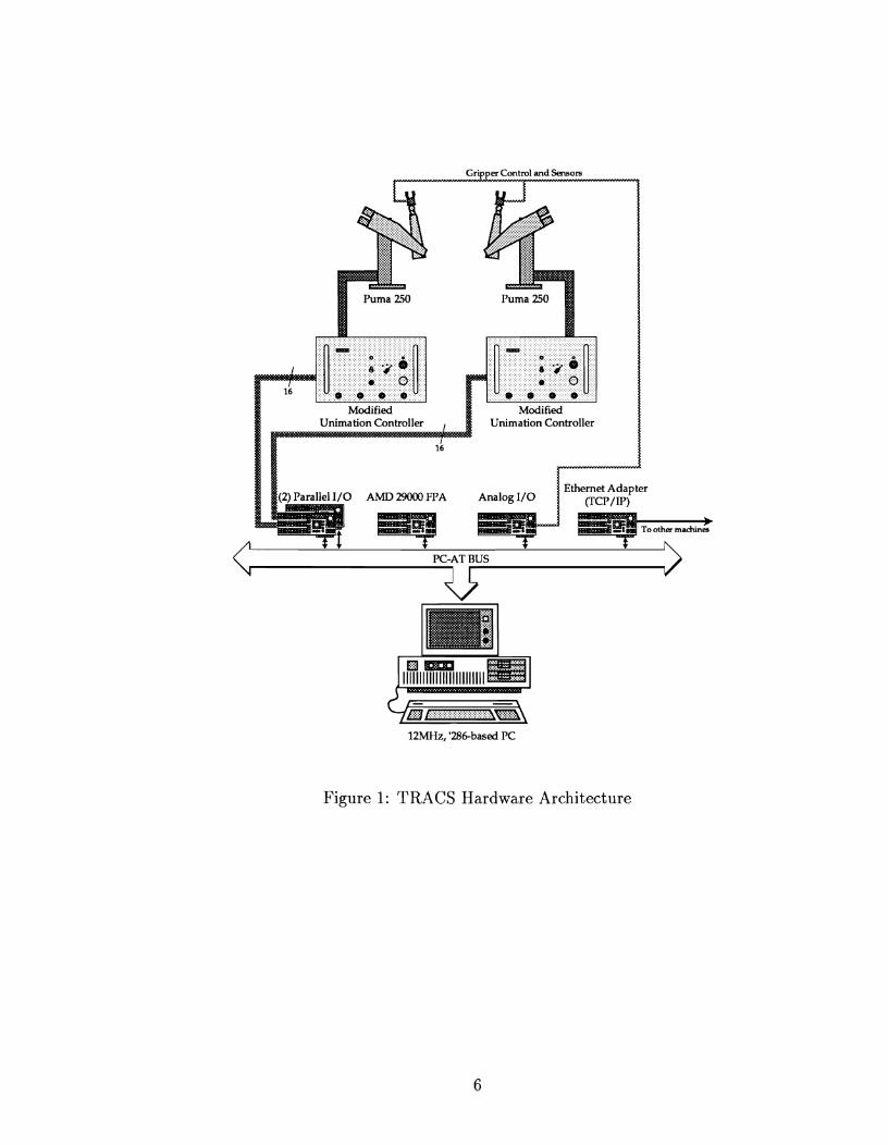
Many commercially available grippers are composed of parallel motion or angular motion finger pairs. The angular motion fingers often do not open more than 15 degrees due to their intended purpose of grasping objects of known dimensions between the two fingers. These types of grippers do not lend themselves toward two-arm manipulation of relatively large objects. The TRACS gripper is capable of opening each finger 90 degrees. Thus, the two arms can conceivably manipulate large objects just as a person uses both arms and open hands to lift such objects. This point is illustrated in Fig. 3.
Gripper Conhol and Sensors I
Figure 1: TRACS Hardware Architecture
Parallel Fingered
Figure 2: TRACS End Effectors
Angular Fingered
Figure 3: Gripper Types
Contad Area Dependency
Force - lbs.
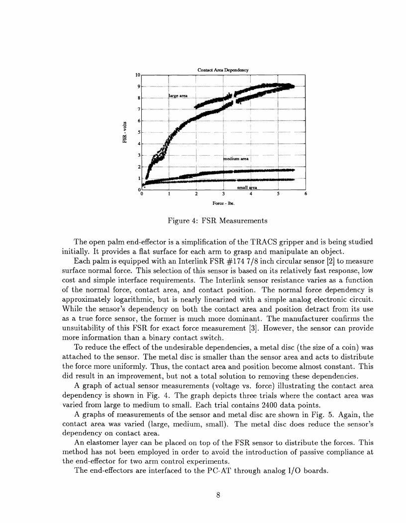
Figure 4: FSR Measurements
The open palm end-effector is a simplification of the TRACS gripper and is being studied initially. It provides a flat surface for each arm to grasp and manipulate an object.
Each palm is equipped with an Interlink FSR #I74 718 inch circular sensor [2] to measure surface normal force. This selection of this sensor is based on its relatively fast response, low cost and simple interface requirements. The Interlink sensor resistance varies as a function of the normal force, contact area, and contact position. The normal force dependency is approximately logarithmic, but is nearly linearized with a simple analog electronic circuit. While the sensor's dependency on both the contact area and position detract from its use as a true force sensor, the former is much more dominant. The manufacturer confirms the unsuitability of this FSR for exact force measurement [3]. However, the sensor can provide more information than a binary contact switch.
To reduce the effect of the undesirable dependencies, a metal disc (the size of a coin) was attached to the sensor. The metal disc is smaller than the sensor area and acts to distribute the force more uniformly. Thus, the contact area and position become almost constant. This did result in an improvement, but not a total solution to removing these dependencies.
A graph of actual sensor measurements (voltage vs. force) illustrating the contact area dependency is shown in Fig. 4. The graph depicts three trials where the contact area was varied from large to medium to small. Each trial contains 2400 data points.
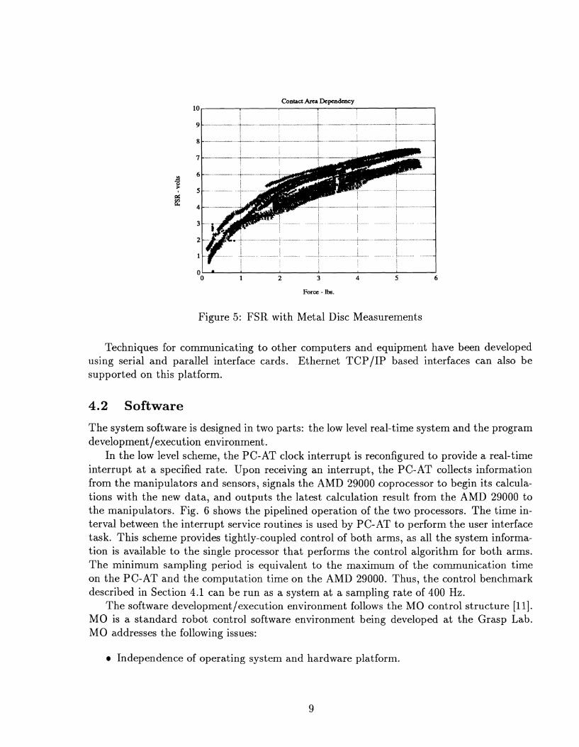
A graphs of measurements of the sensor and metal disc are shown in Fig. 5. Again, the contact area was varied (large, medium, small). The metal disc does reduce the sensor's dependency on contact area.
An elastomer layer can be placed on top of the FSR sensor to distribute the forces. This method has not been employed in order to avoid the introduction of passive compliance at the end-effector for two arm control experiments.
The end-effectors are interfaced to the PC- AT through analog 1/0 boards.
Contact AreP Dependency 10
Force - lbs.
Figure 5 : FSR with Metal Disc Measurements
Techniques for communicating to other computers and equipment have been developed using serial and parallel interface cards. Ethernet TCP/IP based interfaces can also be supported on this platform.
4.2 Software
The system software is designed in two parts: the low level real-time system and the program development /execution environment.
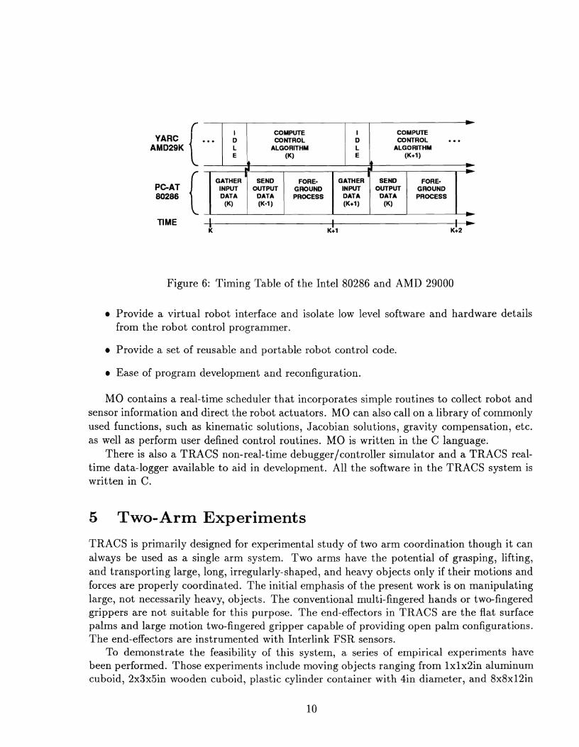
In the low level scheme, the PC-AT clock interrupt is reconfigured to provide a real-time interrupt at a specified rate. Upon receiving an interrupt, the PC-AT collects information from the manipulators and sensors, signals the AMD 29000 coprocessor to begin its calcula- tions with the new data, and outputs the latest calculation result from the AMD 29000 to the manipulators. Fig. 6 shows the pipelined operation of the two processors. The time in- terval between the interrupt service routines is used by PC-AT to perform the user interface task. This scheme provides tightly-coupled control of both arms, as all the system informa- tion is available to the single processor that performs the control algorithm for both arms. The minimum sampling period is equivalent to the maximum of the communication time on the PC-AT and the computation time on the AMD 29000. Thus, the control benchmark described in Section 4.1 can be run as a system at a sampling rate of 400 Hz.
The software development/execution environment follows the MO control structure [l 11 . MO is a standard robot control software environment being developed at the Grasp Lab. MO addresses the following issues:
Independence of operating system and hardware platform.
COMPUTE COMPUTE YARC I ... 1 b 1 m w r R o r 1 b 1 mwrRoL ...
AMD29K \ I i ( ALGORITHM : I ALGORITHM (K) (K+l)
L I k I k + d d *
GATHER SEND FORE- GATHER SEND FORE- PC-AT INPUT OUTPUT GROUND INPUT OUTPUT GROUND
Figure 6: Timing Table of the Intel 80286 and AMD 29000
Provide a virtual robot interface and isolate low level software and hardware details from the robot control programmer.
Provide a set of reusable and portable robot control code.
Ease of program development and reconfiguration.
MO contains a real-time scheduler that incorporates simple routines to collect robot and sensor information and direct the robot actuators. MO can also call on a library of commonly used functions, such as kinematic solutions, Jacobian solutions, gravity compensation, etc. as well as perform user defined control routines. MO is written in the C language.
There is also a TRACS non-real-time debugger/controller simulator and a TRACS real- time data-logger available to aid in development. All the software in the TRACS system is written in C.
5 Two- Arm Experiments
TRACS is primarily designed for experimental study of two arm coordination though it can always be used as a single arm system. Two arms have the potential of grasping, lifting, and transporting large, long, irregularly-shaped, and heavy objects only if their motions and forces are properly coordinated. The initial emphasis of the present work is on manipulating large, not necessarily heavy, objects. The conventional multi-fingered hands or two-fingered grippers are not suitable for this purpose. The end-effectors in TRACS are the flat surface palms and large motion two-fingered gripper capable of providing open palm configurations. The end-effectors are instrumented with Interlink FSR sensors.
To demonstrate the feasibility of this system, a series of empirical experiments have been performed. Those experiments include moving objects ranging from lxlx2in aluminum cuboid, 2x3x5in wooden cuboid, plastic cylinder container with 4in diameter, and 8x8x12in
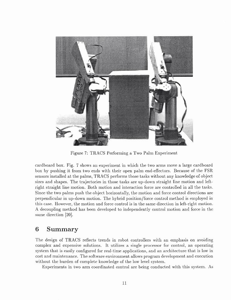
Figure 7: TRACS Performing a Two Palm Experiment
cardboard box. Fig. 7 shows an experiment in which the two arms move a large cardboard box by pushing it from two ends with their open palm end-effectors. Because of the FSR sensors installed at the palms, TRACS performs those tasks without any knowledge of object sizes and shapes. The trajectories in those tasks are up-down straight line motion and left- right straight line motion. Both motion and interaction force are controlled in all the tasks. Since the two palms push the object horizontally, the motion and force control directions are perpendicular in up-down motion. The hybrid position/force control method is employed in this case. However, the motion and force control is in the same direction in left-right motion. A decoupling method has been developed to independently control motion and force in the same direction [20].
Summary
The design of TRACS reflects trends in robot controllers with an emphasis on avoiding complex and expensive solutions. It utilizes a single processor for control, an operating system that is easily configured for real-time applications, and an architecture that is low in cost and maintenance. The software environment allows program development and execution without the burden of complete knowledge of the low level system.
Experiments in two arm coordinated control are being conducted with this system. As
new ideas in coordinated control are researched, TRACS will provide a platform for experi- ment at ion.
6.1 Acknowledgment
The authors wish to thank John Bradley for his technical design support. This work was in part supported by: Airforce grant AFOSR F49620-85-K-0018, ArmyIDAAG-29-84-K-0061, NSF-CERlDCR82-19196 Ao2, NASA NAG5-1045, ONR SB-35923-0, NIH grant NS-10939 - 11 as part of Cerebro Vascular Research Center, NIH 1-R01-NS-23636-01, NSF INT85-14199, NSF DMC85-17315, ARPA N0014-88-K-0632, NATO grant No. 0224185, DEC Corp., IBM Corp., and LORD Corp.
References
[l] AT-Super User's Manual. Yarc Systems Corporation, 1989.
[2] FSR Design Kit Parts Catalog. Interlink Electronics, 1989.
[3] Product Design Guide. Interlink Electronics, July 1989.
[4] R.L. Adnersson. Computer archetectures for robot control: a comparison and a new processor delivering 20 real mflops. In Proceedings of the IEEE International Conference on Robotics and Automation, pages 1160-1167, Scottsdale, Arizona, May 1989.
[5] R.L. Adnersson. System design for robot control with a scalar supercomputer. In Pro- ceedings of the IEEE International Conference on Robotics and Automation, pages 1210- 1215, Cincinnati, Ohio, May 1990.
[6] D. G. Bihn and T. C. S. Hsia. Universal six-joint robot controller. IEEE Control Systems Magazine, 8(1):31-36, February 1988.
[7] Peter I. Corke. A New Approach to Laboratory Motor Control, MMCS: The Modular Motor Control System. Technical Report MS-CIS-89-17, GRASP LAB 175, Dept. of Computer and Information Science, University of Pennsylvania, 1989.
[8] John J. Craig. Introduction to Robotics: Mechanics and Control. Addison Wesley Publishing Company, 2nd edition, 1989.
[9] G. F. Franklin and J . D. Powell. Digital Control of Dynamic Systems. Addison-Wesley Publishing Co., Inc., Reading, Mass., 1980.
[lo] Samad A. Hayati. Position and force control of coordinated multiple arms. IEEE Transactions on Aerospace and Electronic Systems, 24(5):584-590, September 1988.
[l 11 Gaylord Holder. Mo robot control software. December 1989. GRASP lab, University of Pennsylvania.
[12] J. Ish-Shalom and P. Kazanzides. SPARTA: multiple signal processors for high- performance robot control. IEEE Transactions on Robotics and Automation, 5(5):628- 640, October 1989.
[13] Kab I. Kim and Yuan F. Zheng. Two strategies of position and force control for two industrial robots handling a single object. Robotics and Autonomous Systems, (5):395- 403, 1989.
[14] John Lloyd. Implementation of a Robot Control Development Environment. Master's thesis, McGill University, 1985.
[15] Y. Nakamura, K. Nagai, and T. Yoshikawa. Mechanics of coordinative manipulation by multiple robotic mechanisms. In Proceedings of the IEEE International Conference on Robotics and Automation, pages 991-998, Raleigh, North Carolina, 1987.
[16] S. Narasimhan, D. M. Siegel, and J . M. Hollerbach. CONDOR: an architecture for con- trolling the utah-MIT dexterous hand. IEEE Transactions on Robotics and Automation, 5(5):616-627, October 1989.
[17] D. Schmitz, P. Khosla, R. Hoffman, and T . Kanade. CHIMERA: a real-time program- ming environment for manipulator control. In Proceedings of the IEEE International Conference on Robotics and Automation, pages 846-852, Scottsdale, Arizona, May 1989.
[18] T . J . Tarn, A. K. Bejczy, and X. Yun. New nonlinear control algorithms for multiple robot arms. IEEE Transactions on Aerospace and Electronic Systems, 24(5):571-583, September 1988.
[19] Tsuneo Yoshikawa and Xinzhi Zheng. Coordinated dynamic hybrid position/force con- trol for multiple robot manipulators handling one constrained object. In Proceedings of the IEEE International Conference on Robotics and Automation, pages 1178-1183, 1990.
[20] Xiaoping Yun. Coordination of two-arm pushing. Submitted to the Proceedings of the IEEE International Conference on Robotics and Automation, 1991.
[21] Hong Zhang. Design and Implementation of a Robot Force and Motion Server. PhD thesis, Purdue University, 1986. Also available as GRASP Lab Report 77, 1986.
[22] Y. F. Zheng and J. Y. S. Luh. Control of two coordinated robots in motion. In Proceed- ings of IEEE Conference on Decision and Control, pages 1761-1765, Ft . Lauderdale, Florida, December 1985.