Embed Size (px)
Citation preview
11
TracPipe® Design and Installation Specification
OMEGAFLEX®, INC.- ISO 9001 Certified
Manufactured and Kitemarked to British Standard BS 7838 Specification for Corrugated stainless steel semi-rigid pipe and associated
fittings for low-pressure gas pipework of up to DN 50.
FGP-027 Rev. 01/05
May 2007 EDITION
For Corrugated Stainless Steel Semi-Rigid Pipe and Associated Fittings
Design Certified
! WARNING
When installing, servicing, maintaining or repairing gas appliances and other gas fittings in South Africa, there are a number of statutory requirements with which to comply. These compliance issues are discussed in the following paragraphs. When working on gas, compliance should be achieved by carrying out work in accordance with the relevant safety standards listed in the Vessels Under Pressure Regulations found in the Occupational Health and Safety Act (Act 85 of 1993) (OHSA) and the following manufacturers instructions. Gas installers must be competent and hold a valid license for each work activity that they wish to undertake. The valid license must have been issued under the auspices of the South African Qualification and Certification Committee. [SAQCC (LPGI)].
All gas appliances and other gas fittings must be installed in accordance with the following gas regulations found in the schedule of the OHS Act. For Domestic and Commercial LPG installations SANS 10087-1, for LPG Industrial Installations SANS 10078-3, for the building Regulations SANS 10400. Over and above the regulations listed where relevant the manufacturers installation instructions shall also be complied with.
The SAQCC (LPGI) was formed during 1995 and mandated by the Department of Labour to develop and maintain a register of gas installers, for LP Gas. This mandate was given to the Liquefied Petroleum Gas Safety Association of Southern Africa (LPGSASA). Approximately two years later a similar mandate was given to the South African Fuel Gas Association (SAFGA) for the maintenance and registration of Natural Gas installers. The LPGSASA works to a tight remit laid down by the SAQCC (LPGI) criteria, which stipulate how the registration of gas installing businesses should be operated. The criteria must be met in full and require LPGSASA to monitor and inspect installing businesses regularly, to run a public enquiry and complaints service, and to publicize the importance of gas safety and the need to use registered operatives. SAQCC (LPGI) rules for registration require individual installers to be competent to carry out gas work. Competence in safe gas work in relation to gas fittings requires knowledge, understanding and the practical skills to carry out the work in hand in such a way as to prevent danger to life and property.
Only the components provided or specified by OMEGAFLEX® as part of the approved piping system are to be used in the
installation. The use of TracPipe piping or fittings with piping or fittings from other flexible gas piping manufacturers is strictly prohibited and may result in serious bodily injury or property
damage.
If this system is used or installed improperly, fire, explosion or asphyxiation may result. The installation instructions and
applicable Regulations must be strictly followed.

Vapour Energy Consultants Commercial Close George, 6530 Tel: (044) 871-5304 Fax: (044) 871-5508 [email protected]
OMEGAFLEX Ltd 4TH Floor, Apollo House Desborough Road, High Wycombe Bucks HP11 2QW – U.K. Tel: 0870 286 85 85 Fax: 0870 286 85 86 [email protected] www.omegaflex.com
OMEGAFLEX, INC 451 Creamery Way, Exton, PA 19341 USA Tel: +1 610 524-7272 Fax: +1 610 524-7282
2
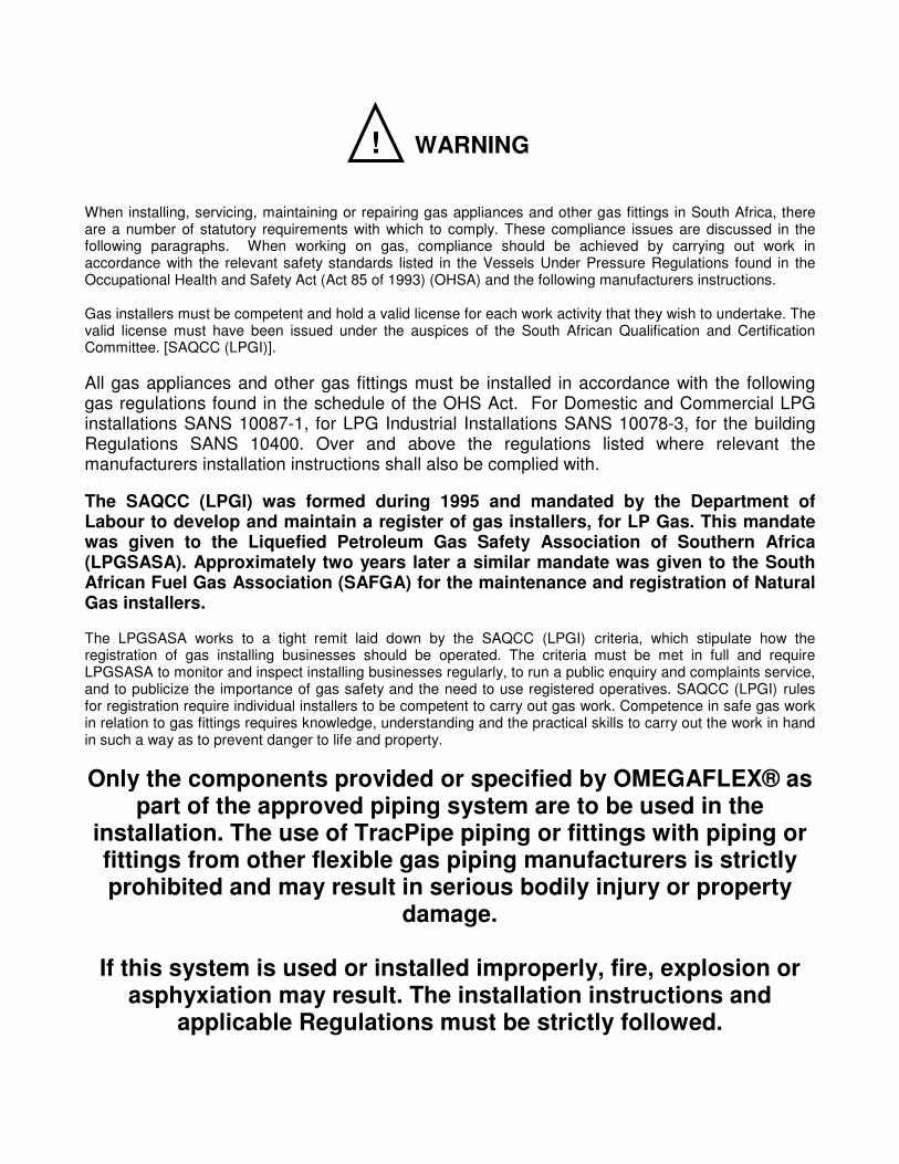
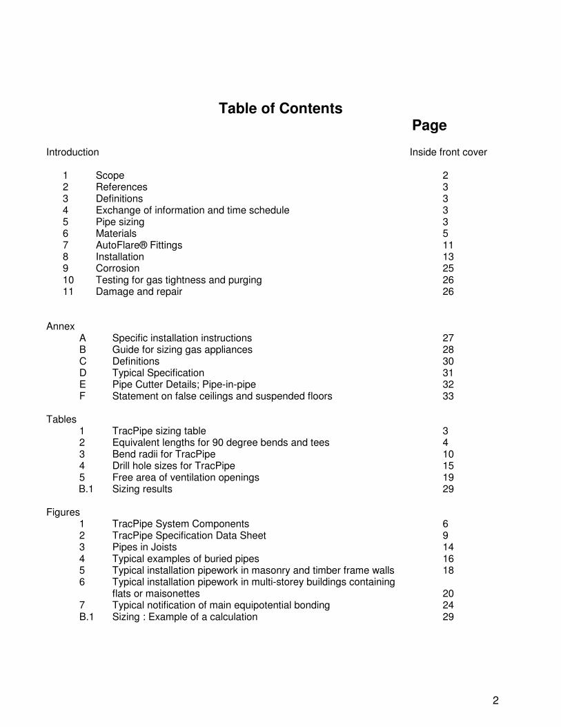
Table of Contents Page
Introduction Inside front cover
1 Scope 2 2 References 3 3 Definitions 3 4 Exchange of information and time schedule 3 5 Pipe sizing 3 6 Materials 5 7 AutoFlare® Fittings 11 8 Installation 13 9 Corrosion 25 10 Testing for gas tightness and purging 26 11 Damage and repair 26
Annex
A Specific installation instructions 27 B Guide for sizing gas appliances 28 C Definitions 30 D Typical Specification 31
E Pipe Cutter Details; Pipe-in-pipe 32 F Statement on false ceilings and suspended floors 33 Tables
1 TracPipe sizing table 3 2 Equivalent lengths for 90 degree bends and tees 4 3 Bend radii for TracPipe 10 4 Drill hole sizes for TracPipe 15 5 Free area of ventilation openings 19 B.1 Sizing results 29
Figures
1 TracPipe System Components 6 2 TracPipe Specification Data Sheet 9 3 Pipes in Joists 14 4 Typical examples of buried pipes 16 5 Typical installation pipework in masonry and timber frame walls 18 6 Typical installation pipework in multi-storey buildings containing
flats or maisonettes 20 7 Typical notification of main equipotential bonding 24 B.1 Sizing : Example of a calculation 29
2
TracPipe® by OMEGAFLEX® Design and Installation Specification
1 SCOPE British Standards Institution has granted Kitemark Licence Number KM 52508 to OmegaFlex. This Kitemark can be affixed to all sizes of TracPipe which are in conformity with BS 7838 : 1996 Corrugated stainless steel semi-rigid pipe and associated fittings for low pressure gas pipework of up to 50mm. This Kitemark Licence covers TracPipe sizes 12, 15, 22, 28, 32, 40 and 50mm – and their associated fittings. BS 7838 specifies requirements for semi-rigid (bendable) corrugated stainless steel pipe and associated fittings in the nominal size range DN 10 to DN 50 and intended for use as installation pipework for the supply of 1st, 2nd and 3rd family gases in permanent buildings. It applies to corrugated pipe and fittings that are suitable for a maximum working pressure of 75 mbar when installed in accordance with BS 6891 or BS 5482 Part 1 in domestic premises, or in accordance with the Institution of Gas Engineers publication IGE/UP/2 in other premises. This document contains portions of BS 6891 language where appropriate, (for which we are grateful to British Standards Institution), which is the installation specification for low pressure natural gas pipework of up to 28 mm in domestic premises. This standard applies to gas installation pipework where the nominal working pressure is 21 mbar. SANS 10087 Part 1 specifies requirements for the installation at permanent dwellings of domestic systems using liquefied petroleum gases (LPG), from cylinders and SANS 10087 Part 3 from bulk supply, at a pressure of 28 mbar for commercial butane and of 37 mbar for commercial propane.
TracPipe is Kitemarked to BS 7838, in all sizes, including the diameters larger than 28 mm (32, 40 and 50 mm). The installation of pipework in sizes above 28 mm and for working pressures above 21 mbar falls under the Institution of Gas Engineers and Managers Utilization Procedures IGE/UP/2. BS 7838 being a relatively new specification is not currently referred to in IGEM publications, however, clause 2.6 of IGE/UP/2 permits stainless steel piping to be specified, and the general installation principles are similar to those outlined in BS 6891. We understand IGE/UP/2 will be revised once BS EN 1775 has been revised and published. (The draft revision of EN 1775 includes BS 7838 product as ‘pliable’ stainless steel tubing). TracPipe has North American approvals for working pressures to 125 psi and we would be pleased to discuss potential applications for working pressures in excess of 75 mbar outside the normal installation operation. TracPipe has a test pressure of 20 bar, an operating pressure of 8 bar and burst pressure of 186 bar. Sound engineering principles and practices must be exercised for the proper design of fuel gas piping systems, in addition to compliance with Gas Safety, Building Standards Regulations and with British Standards requirements. The installation instructions and procedures contained in this Specification must be strictly followed in order to provide a safe and effective fuel gas piping system or system modification. This Specification is intended to aid the SAQCC registered gas installer in the design, installation and testing of the TracPipe® semi-rigid gas piping system.
3
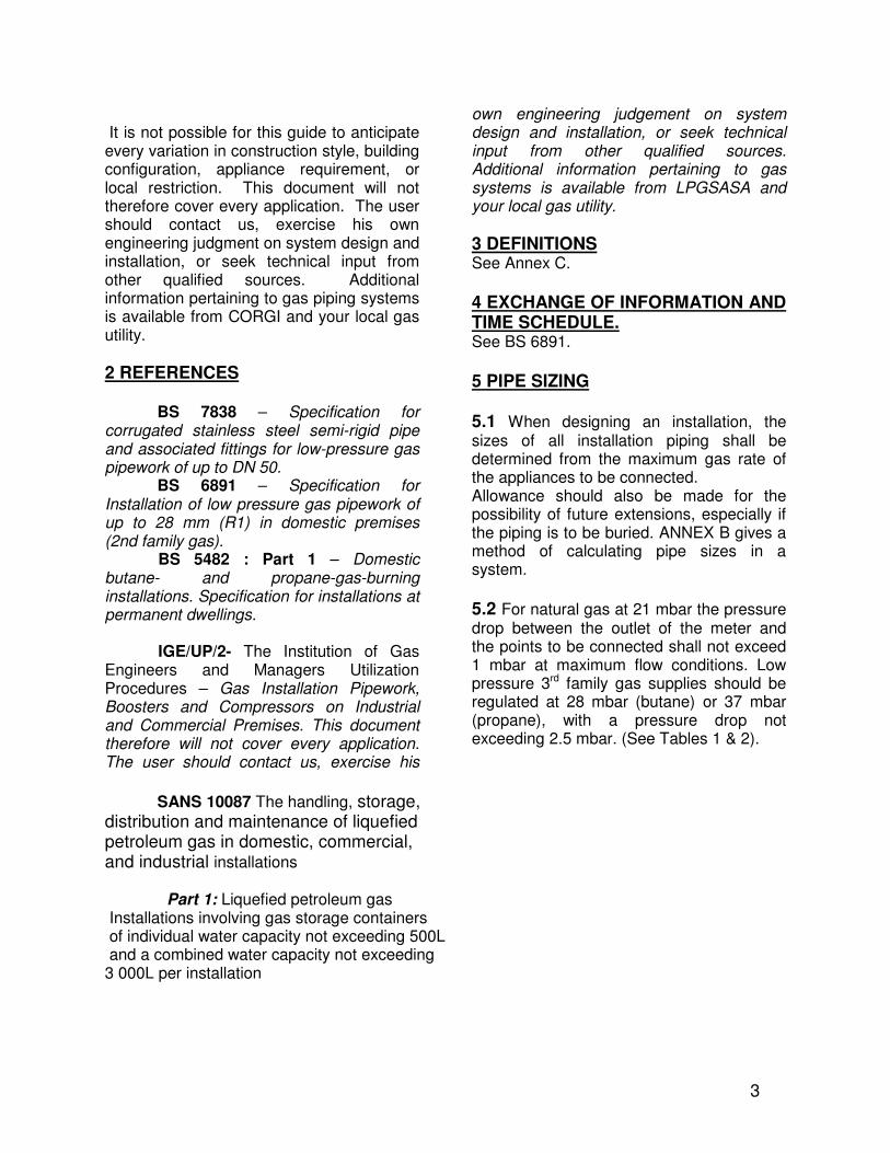
It is not possible for this guide to anticipate every variation in construction style, building configuration, appliance requirement, or local restriction. This document will not therefore cover every application. The user should contact us, exercise his own engineering judgment on system design and installation, or seek technical input from other qualified sources. Additional information pertaining to gas piping systems is available from CORGI and your local gas utility.
2 REFERENCES BS 7838 – Specification for corrugated stainless steel semi-rigid pipe and associated fittings for low-pressure gas pipework of up to DN 50. BS 6891 – Specification for Installation of low pressure gas pipework of up to 28 mm (R1) in domestic premises (2nd family gas). BS 5482 : Part 1 – Domestic butane- and propane-gas-burning installations. Specification for installations at permanent dwellings. IGE/UP/2- The Institution of Gas Engineers and Managers Utilization Procedures – Gas Installation Pipework, Boosters and Compressors on Industrial and Commercial Premises. This document therefore will not cover every application. The user should contact us, exercise his
own engineering judgement on system design and installation, or seek technical input from other qualified sources. Additional information pertaining to gas systems is available from LPGSASA and your local gas utility.
3 DEFINITIONS See Annex C. 4 EXCHANGE OF INFORMATION AND TIME SCHEDULE. See BS 6891. 5 PIPE SIZING 5.1 When designing an installation, the sizes of all installation piping shall be determined from the maximum gas rate of the appliances to be connected. Allowance should also be made for the possibility of future extensions, especially if the piping is to be buried. ANNEX B gives a method of calculating pipe sizes in a system.
5.2 For natural gas at 21 mbar the pressure drop between the outlet of the meter and the points to be connected shall not exceed 1 mbar at maximum flow conditions. Low pressure 3rd family gas supplies should be regulated at 28 mbar (butane) or 37 mbar (propane), with a pressure drop not exceeding 2.5 mbar. (See Tables 1 & 2).
SANS 10087 The handling, storage, distribution and maintenance of liquefied petroleum gas in domestic, commercial, and industrial installations Part 1: Liquefied petroleum gas Installations involving gas storage containers of individual water capacity not exceeding 500L and a combined water capacity not exceeding 3 000L per installation
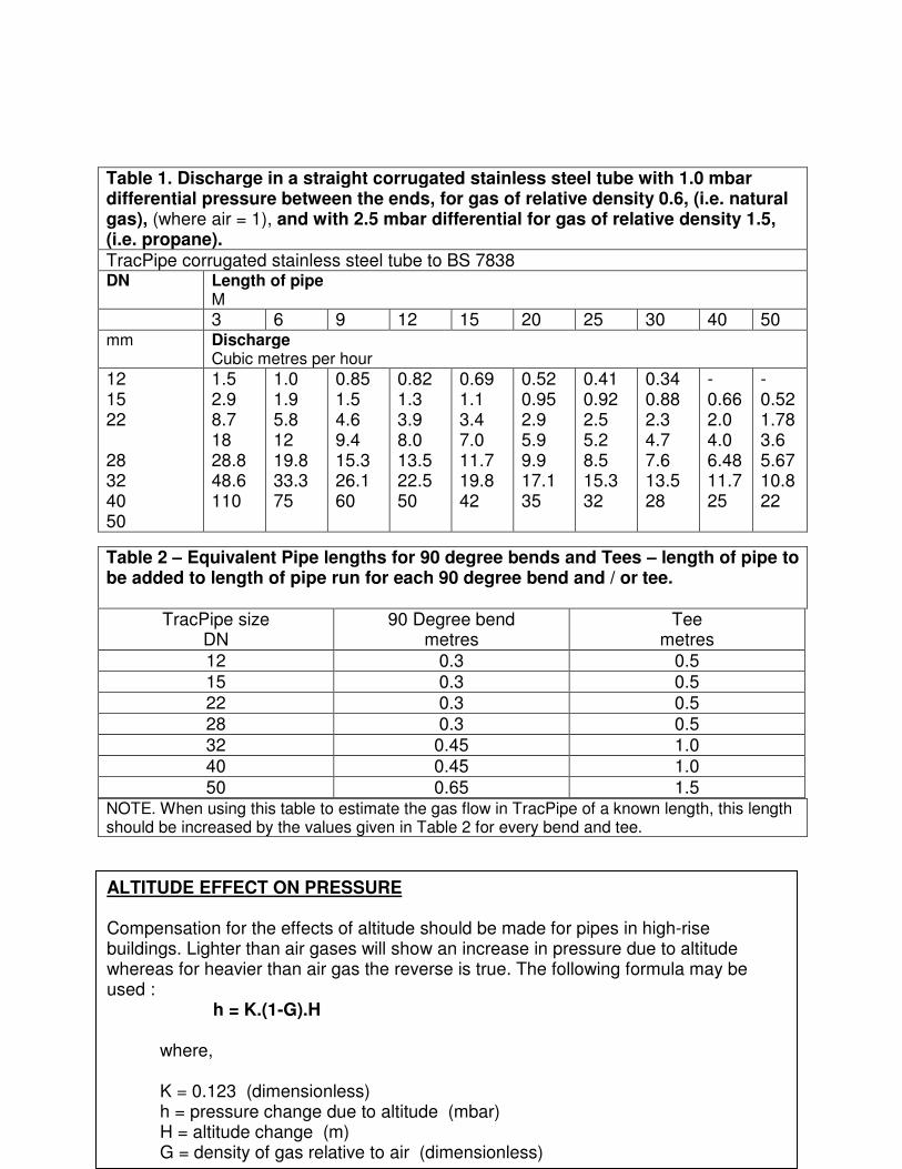
Table 1. Discharge in a straight corrugated stainless steel tube with 1.0 mbar differential pressure between the ends, for gas of relative density 0.6, (i.e. natural gas), (where air = 1), and with 2.5 mbar differential for gas of relative density 1.5, (i.e. propane). TracPipe corrugated stainless steel tube to BS 7838 DN Length of pipe
M
3 6 9 12 15 20 25 30 40 50 mm Discharge
Cubic metres per hour
12 15 22 28 32 40 50
1.5 2.9 8.7 18 28.8 48.6 110
1.0 1.9 5.8 12 19.8 33.3 75
0.85 1.5 4.6 9.4 15.3 26.1 60
0.82 1.3 3.9 8.0 13.5 22.5 50
0.69 1.1 3.4 7.0 11.7 19.8 42
0.52 0.95 2.9 5.9 9.9 17.1 35
0.41 0.92 2.5 5.2 8.5 15.3 32
0.34 0.88 2.3 4.7 7.6 13.5 28
- 0.662.0 4.0 6.48 11.7 25
- 0.52 1.78 3.6 5.67 10.8 22
NOTE. When using this table to estimate the gas flow in TracPipe of a known length, this length should be increased by the values given in Table 2 for every bend and tee.
Table 2 – Equivalent Pipe lengths for 90 degree bends and Tees – length of pipe to be added to length of pipe run for each 90 degree bend and / or tee.
TracPipe size DN
90 Degree bend metres
Tee metres
12 0.3 0.5 15 0.3 0.5 22 0.3 0.5 28 0.3 0.5 32 0.45 1.0 40 0.45 1.0 50 0.65 1.5
ALTITUDE EFFECT ON PRESSURE Compensation for the effects of altitude should be made for pipes in high-rise buildings. Lighter than air gases will show an increase in pressure due to altitude whereas for heavier than air gas the reverse is true. The following formula may be used : h = K.(1-G).H where, K = 0.123 (dimensionless) h = pressure change due to altitude (mbar) H = altitude change (m) G = density of gas relative to air (dimensionless)
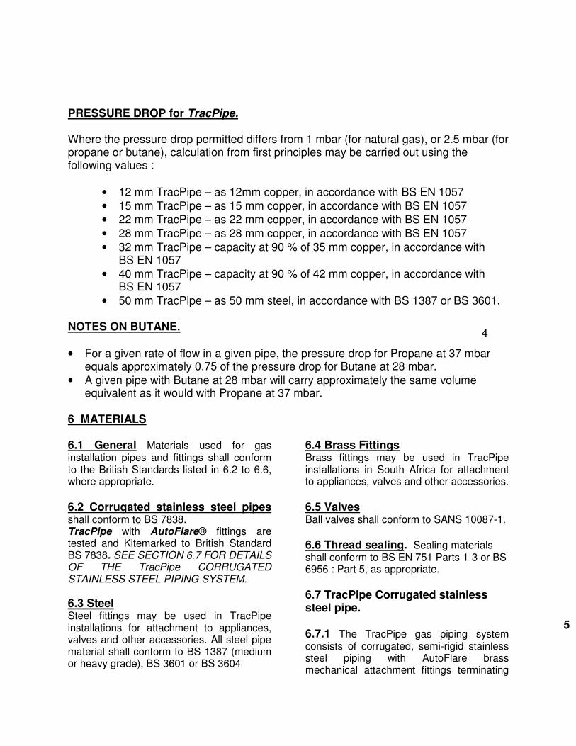
PRESSURE DROP for TracPipe. Where the pressure drop permitted differs from 1 mbar (for natural gas), or 2.5 mbar (for propane or butane), calculation from first principles may be carried out using the following values :
• 12 mm TracPipe – as 12mm copper, in accordance with BS EN 1057
• 15 mm TracPipe – as 15 mm copper, in accordance with BS EN 1057
• 22 mm TracPipe – as 22 mm copper, in accordance with BS EN 1057
• 28 mm TracPipe – as 28 mm copper, in accordance with BS EN 1057
• 32 mm TracPipe – capacity at 90 % of 35 mm copper, in accordance with BS EN 1057
• 40 mm TracPipe – capacity at 90 % of 42 mm copper, in accordance with BS EN 1057
• 50 mm TracPipe – as 50 mm steel, in accordance with BS 1387 or BS 3601. NOTES ON BUTANE.
• For a given rate of flow in a given pipe, the pressure drop for Propane at 37 mbar equals approximately 0.75 of the pressure drop for Butane at 28 mbar.
• A given pipe with Butane at 28 mbar will carry approximately the same volume equivalent as it would with Propane at 37 mbar.
6 MATERIALS 6.1 General Materials used for gas installation pipes and fittings shall conform to the British Standards listed in 6.2 to 6.6, where appropriate.
6.2 Corrugated stainless steel pipes shall conform to BS 7838. TracPipe with AutoFlare® fittings are tested and Kitemarked to British Standard BS 7838. SEE SECTION 6.7 FOR DETAILS OF THE TracPipe CORRUGATED STAINLESS STEEL PIPING SYSTEM.
6.3 Steel Steel fittings may be used in TracPipe installations for attachment to appliances, valves and other accessories. All steel pipe material shall conform to BS 1387 (medium or heavy grade), BS 3601 or BS 3604
6.4 Brass Fittings Brass fittings may be used in TracPipe installations in South Africa for attachment to appliances, valves and other accessories.
6.5 Valves Ball valves shall conform to SANS 10087-1. 6.6 Thread sealing. Sealing materials shall conform to BS EN 751 Parts 1-3 or BS 6956 : Part 5, as appropriate.
6.7 TracPipe Corrugated stainless steel pipe. 6.7.1 The TracPipe gas piping system consists of corrugated, semi-rigid stainless steel piping with AutoFlare brass mechanical attachment fittings terminating
4
5
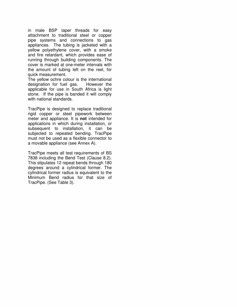
in male BSP taper threads for easy attachment to traditional steel or copper pipe systems and connections to gas appliances. The tubing is jacketed with a yellow polyethylene cover, with a smoke and fire retardant, which provides ease of running through building components. The cover is marked at one-meter intervals with the amount of tubing left on the reel, for quick measurement. The yellow ochre colour is the international designation for fuel gas. However the applicable for use in South Africa is light stone. If the pipe is banded it will comply with national standards. TracPipe is designed to replace traditional rigid copper or steel pipework between meter and appliance. It is not intended for applications in which during installation, or subsequent to installation, it can be subjected to repeated bending. TracPipe must not be used as a flexible connector to a movable appliance (see Annex A). TracPipe meets all test requirements of BS 7838 including the Bend Test (Clause 8.2). This stipulates 12 repeat bends through 180 degrees around a cylindrical former. The cylindrical former radius is equivalent to the Minimum Bend radius for that size of TracPipe. (See Table 3).
6
TracPipe
DN Standard Reel Lengths Weights
Kilograms
12 75 metres 13.2 Kg
15 75 metres 30 metres
18.2 Kg 10.0 Kg
22 75 metres 30 metres
25.0 Kg 10.0 Kg
28 55 metres 90 metres
27.3 Kg 48.0 Kg
32 45 metres 75 metres
30.0 Kg 52.3 Kg
40 45 metres 75 metres
36.8 Kg 62.5 Kg
50 45 metres 41.8 Kg
DN 12 15 22 28 32 40 50 Inch 3/8” 1/2” 3/4” 1” 1.1/4” 1.1/2” 2”
Jacket O.D. (max) mm 17 22 28 35 42 49 66
Inside Dia. (nom) mm 11 15 21 27 33 39 52
Figure 1: TracPipe System Components Corrugated Stainless Steel Pipe
7737333377773977
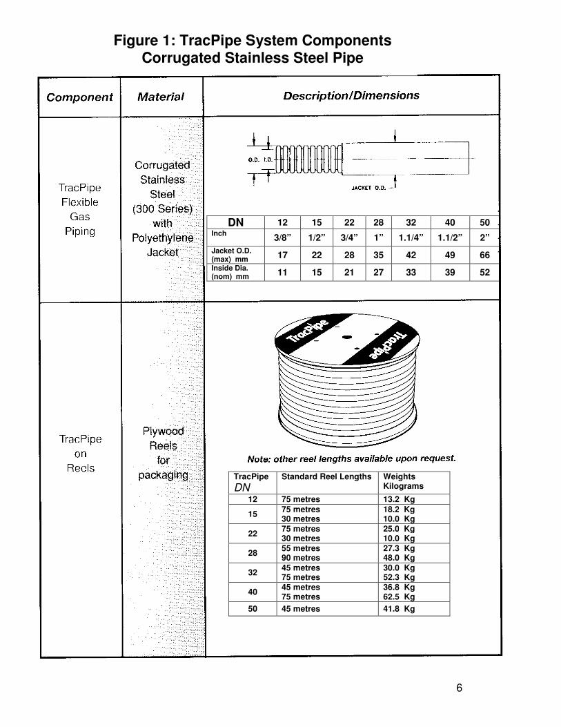
Sizes: DN 12, 15, 22, 28, 32, 40, and 50
Sizes: DN 12, 15, 22, 28, and 32
Sizes DN 12 and DN 15
Sizes: DN 12,15, 22, 28
Sizes: DN 12,15, 22, 28, 32, 40, and 50
Figure 1 (contd): TracPipe System Components
AutoFlare® Fittings
7
10
,
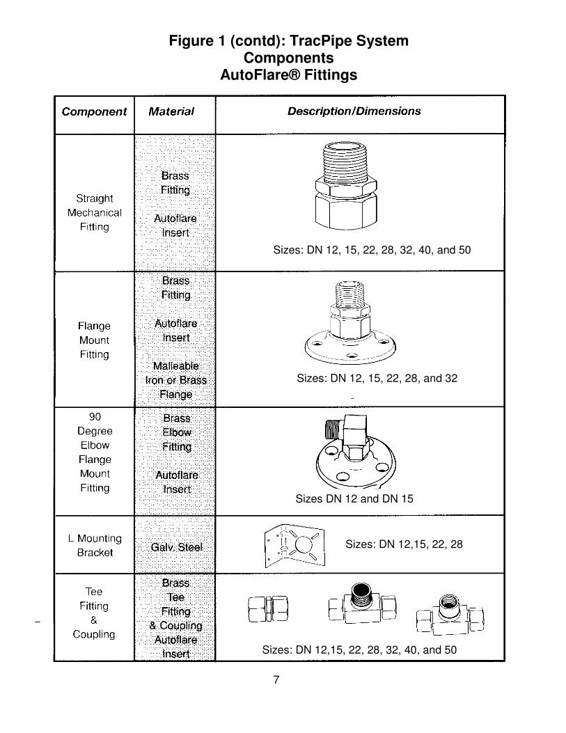
Size: 102mm x 305mm
Size: 102mm x 152mm
Size: 102mm x 51mm
Size: 152mm x 432mm
Sizes: fits DN 12, 15, 22, 28, 32, 40, 50
Figure 1 (contd): TracPipe System Components
Protection Devices
8
10
AVAILABLE IN SIZES
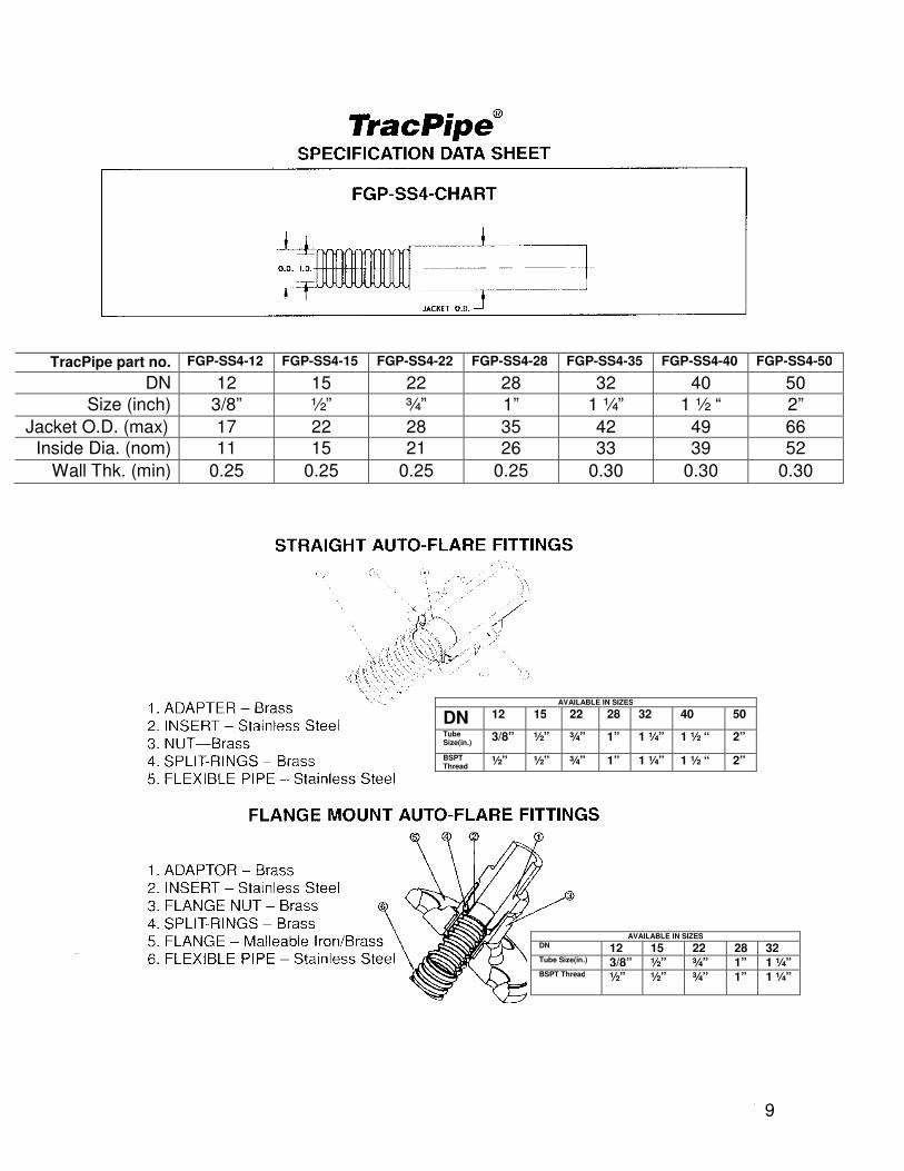
DN 12 15 22 28 32 Tube Size(in.) 3/8” ½” ¾” 1” 1 ¼” BSPT Thread ½” ½” ¾” 1” 1 ¼”
AVAILABLE IN SIZES
DN 12 15 22 28 32
Tube Size(in.) 3/8” ½” ¾” 1” 1 ¼”
BSPT Thread ½” ½” ¾” 1” 1 ¼”
TracPipe part no. FGP-SS4-12 FGP-SS4-15 FGP-SS4-22 FGP-SS4-28 FGP-SS4-35 FGP-SS4-40 FGP-SS4-50
DN 12 15 22 28 32 40 50
Size (inch) 3/8” ½” ¾” 1” 1 ¼” 1 ½ “ 2”
Jacket O.D. (max) 17 22 28 35 42 49 66
Inside Dia. (nom) 11 15 21 26 33 39 52
Wall Thk. (min) 0.25 0.25 0.25 0.25 0.30 0.30 0.30
AVAILABLE IN SIZES
DN 12 15 22 28 32 40 50
Tube Size(in.)
3/8” ½” ¾” 1” 1 ¼” 1 ½ “ 2”
BSPT Thread
½” ½” ¾” 1” 1 ¼” 1 ½ “ 2”
9
10
6.7.2 Additional fittings include flange mount straight and 90-degree elbows for termination of gas lines near appliances and at meter boxes on building exteriors. Tee fittings are available for addition of branch lines into tubing runs.
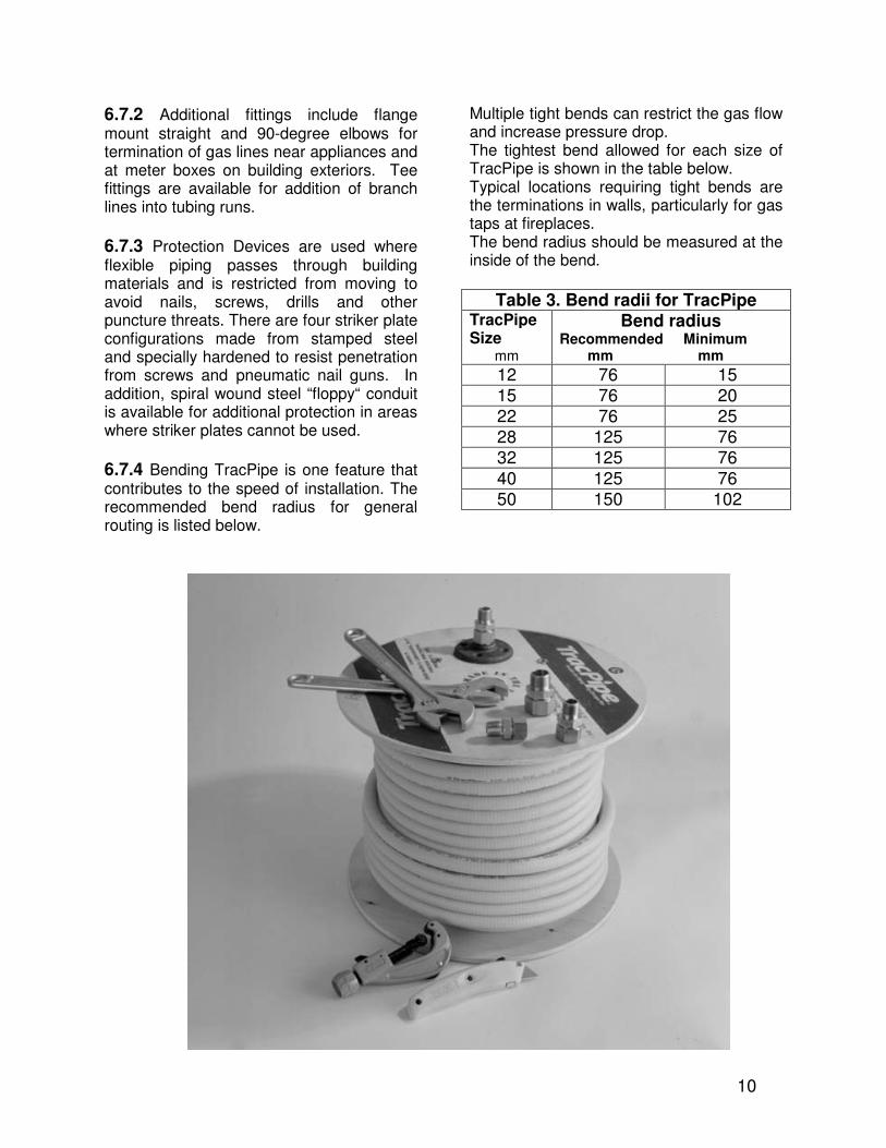
6.7.3 Protection Devices are used where flexible piping passes through building materials and is restricted from moving to avoid nails, screws, drills and other puncture threats. There are four striker plate configurations made from stamped steel and specially hardened to resist penetration from screws and pneumatic nail guns. In addition, spiral wound steel “floppy“ conduit is available for additional protection in areas where striker plates cannot be used.
6.7.4 Bending TracPipe is one feature that contributes to the speed of installation. The recommended bend radius for general routing is listed below.
Multiple tight bends can restrict the gas flow and increase pressure drop. The tightest bend allowed for each size of TracPipe is shown in the table below. Typical locations requiring tight bends are the terminations in walls, particularly for gas taps at fireplaces. The bend radius should be measured at the inside of the bend.
Table 3. Bend radii for TracPipe
TracPipe Size
mm
Bend radius Recommended Minimum mm mm
12 76 15 15 76 20 22 76 25 28 125 76 32 125 76 40 125 76 50 150 102
10
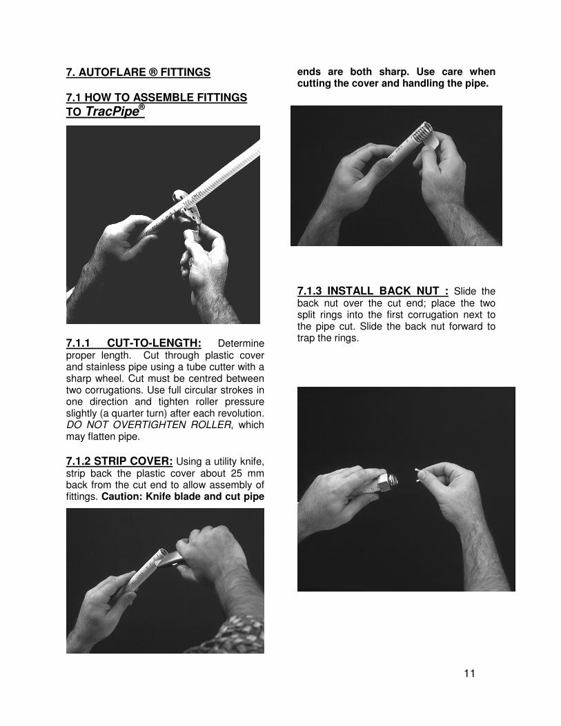
7. AUTOFLARE ® FITTINGS 7.1 HOW TO ASSEMBLE FITTINGS
TO TracPipe®
7.1.1 CUT-TO-LENGTH: Determine proper length. Cut through plastic cover and stainless pipe using a tube cutter with a sharp wheel. Cut must be centred between two corrugations. Use full circular strokes in one direction and tighten roller pressure slightly (a quarter turn) after each revolution. DO NOT OVERTIGHTEN ROLLER, which may flatten pipe.
7.1.2 STRIP COVER: Using a utility knife, strip back the plastic cover about 25 mm back from the cut end to allow assembly of fittings. Caution: Knife blade and cut pipe
ends are both sharp. Use care when cutting the cover and handling the pipe.
7.1.3 INSTALL BACK NUT : Slide the back nut over the cut end; place the two split rings into the first corrugation next to the pipe cut. Slide the back nut forward to trap the rings.
11
10
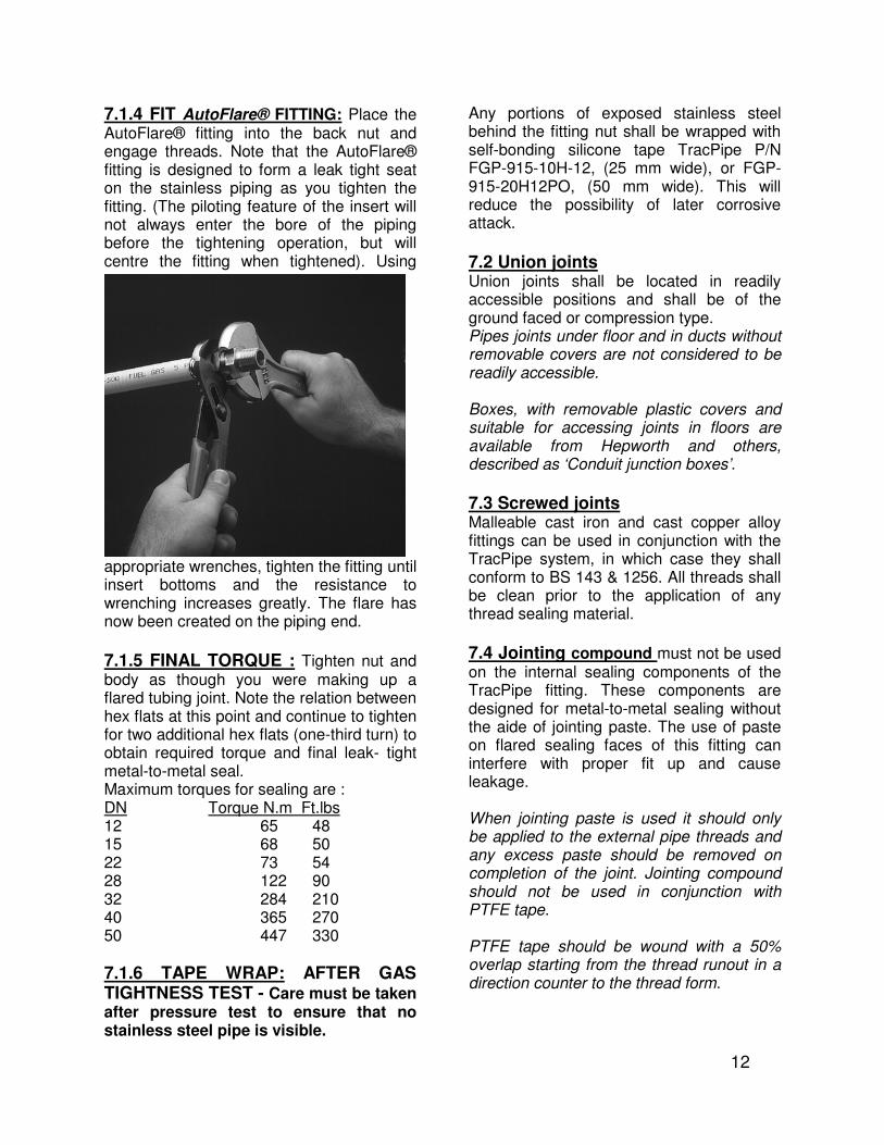
7.1.4 FIT AutoFlare® FITTING: Place the AutoFlare® fitting into the back nut and engage threads. Note that the AutoFlare® fitting is designed to form a leak tight seat on the stainless piping as you tighten the fitting. (The piloting feature of the insert will not always enter the bore of the piping before the tightening operation, but will centre the fitting when tightened). Using
appropriate wrenches, tighten the fitting until insert bottoms and the resistance to wrenching increases greatly. The flare has now been created on the piping end.
7.1.5 FINAL TORQUE : Tighten nut and body as though you were making up a flared tubing joint. Note the relation between hex flats at this point and continue to tighten for two additional hex flats (one-third turn) to obtain required torque and final leak- tight metal-to-metal seal. Maximum torques for sealing are : DN Torque N.m Ft.lbs 12 65 48 15 68 50 22 73 54 28 122 90 32 284 210 40 365 270 50 447 330
7.1.6 TAPE WRAP: AFTER GAS TIGHTNESS TEST - Care must be taken after pressure test to ensure that no stainless steel pipe is visible.
Any portions of exposed stainless steel behind the fitting nut shall be wrapped with self-bonding silicone tape TracPipe P/N FGP-915-10H-12, (25 mm wide), or FGP-915-20H12PO, (50 mm wide). This will reduce the possibility of later corrosive attack.
7.2 Union joints Union joints shall be located in readily accessible positions and shall be of the ground faced or compression type. Pipes joints under floor and in ducts without removable covers are not considered to be readily accessible. Boxes, with removable plastic covers and suitable for accessing joints in floors are available from Hepworth and others, described as ‘Conduit junction boxes’.
7.3 Screwed joints Malleable cast iron and cast copper alloy fittings can be used in conjunction with the TracPipe system, in which case they shall conform to BS 143 & 1256. All threads shall be clean prior to the application of any thread sealing material.
7.4 Jointing compound must not be used on the internal sealing components of the TracPipe fitting. These components are designed for metal-to-metal sealing without the aide of jointing paste. The use of paste on flared sealing faces of this fitting can interfere with proper fit up and cause leakage. When jointing paste is used it should only be applied to the external pipe threads and any excess paste should be removed on completion of the joint. Jointing compound should not be used in conjunction with PTFE tape. PTFE tape should be wound with a 50% overlap starting from the thread runout in a direction counter to the thread form.
12
10
8. INSTALLATION
8.1 General Installation pipework shall be physically protected or located where it is not liable to mechanical damage. The bore of an installation pipe shall not be restricted by kinks, burrs, or foreign matter or in any other way.
8.2 Safety precautions
8.2.1 While installation work is in progress, care shall be taken to prevent the ingress of dirt, water, etc., into installation pipes. 8.2.2 Where work is in progress on pipes already connected to a meter either: a) the meter shall be temporarily disconnected and both the open ends of the pipework sealed and dust caps fitted to the meter; or b) all open ends of the pipework shall be plugged, capped or terminated with a self sealing appliance connector conforming to BS 669: Part 1 or BS 669: Part 2 as appropriate, before the work is left unattended. Installers need to consider the risk of persons restoring the gas supply at the primary meter should they leave the general location where the work is in progress.
8.2.3 When work has been completed, open ends of pipe shall be plugged, capped or terminated with a self-sealing appliance connector conforming to BS 669: Part 1 or BS 669: Part 2, as appropriate.
8.2.4 Before any work is commenced with a naked flame, e.g. a blowlamp, on pipework that contains or has contained gas, the gas supply to that part of the pipework shall be isolated and disconnected. The open ends of pipework connected to the gas supply and of any gas meter shall be plugged or
capped. Naked flames shall be kept away from the open ends of pipework. In no case shall oxy-gas flame cutting equipment be applied to any meter, pipe or fitting containing gas.
8.2.5 Connection and disconnection of pipes and fittings Where any installation pipe is no longer required, the pipe(s) shall be disconnected as close to the point of supply as practicable. All pipe ends shall be sealed, e.g. with a plug or cap. During any work that necessitates connection or disconnection of any installation pipework, a temporary continuity bond shall be fixed where production of a spark or shock could cause a hazard, whether or not permanent equipotential bonding has been established. The recommended disconnection procedure is as follows. a) Isolate the electrical connection of associated gas appliances from the mains supply. b) Clip or clamp a temporary continuity bond to each side of the union, fittings or complete section that is to be removed or connected ensuring that good metallic contact is made. c) Leave the bond in position until after the work is completed and metallic continuity re-established. A recommended temporary continuity bond comprises of at least 1.2 m of single-core insulated flexible cable or equivalent of at least 250 V rating. The cable should have a cross-sectional area of not less than 10 mm2 and multi-strand flexible construction generally in accordance with BS 6004, BS 6007 or BS 6231 with a robust clip or clamp firmly attached at each end. Where the meter is removed BS 6400 should be consulted.
13
10
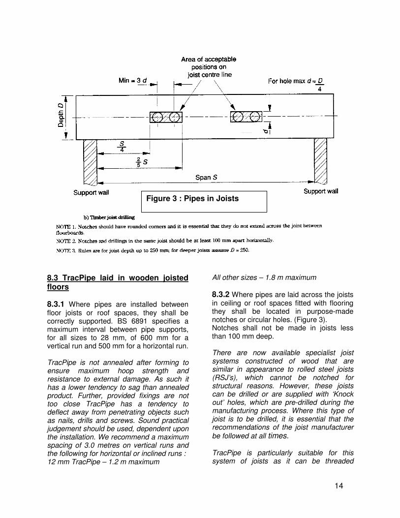
8.3 TracPipe laid in wooden joisted floors
8.3.1 Where pipes are installed between floor joists or roof spaces, they shall be correctly supported. BS 6891 specifies a maximum interval between pipe supports, for all sizes to 28 mm, of 600 mm for a vertical run and 500 mm for a horizontal run. TracPipe is not annealed after forming to ensure maximum hoop strength and resistance to external damage. As such it has a lower tendency to sag than annealed product. Further, provided fixings are not too close TracPipe has a tendency to deflect away from penetrating objects such as nails, drills and screws. Sound practical judgement should be used, dependent upon the installation. We recommend a maximum spacing of 3.0 metres on vertical runs and the following for horizontal or inclined runs : 12 mm TracPipe – 1.2 m maximum
All other sizes – 1.8 m maximum
8.3.2 Where pipes are laid across the joists in ceiling or roof spaces fitted with flooring they shall be located in purpose-made notches or circular holes. (Figure 3). Notches shall not be made in joists less than 100 mm deep. There are now available specialist joist systems constructed of wood that are similar in appearance to rolled steel joists (RSJ’s), which cannot be notched for structural reasons. However, these joists can be drilled or are supplied with ‘Knock out’ holes, which are pre-drilled during the manufacturing process. Where this type of joist is to be drilled, it is essential that the recommendations of the joist manufacturer
be followed at all times. TracPipe is particularly suitable for this system of joists as it can be threaded
Figure 3: Pipes in Joists
14
Figure 3 : Pipes in Joists
10
between joists with ease. Prior to running pipework below suspended floors a visual inspection should be carried out to note the position of any electrical cables, junction boxes and ancillary equipment, in order that accidental damage or injury does not occur when inserting
pipework. Care should be taken when refixing flooring to prevent damage to the pipe by nails or screws. Where possible, the flooring should be appropriately marked to warn others.
Table 4. Drill hole sizes for TracPipe
TracPipe Size mm
Drill hole size mm
12 28 15 35 22 38 28 45 32 57 40 63.5 50 76
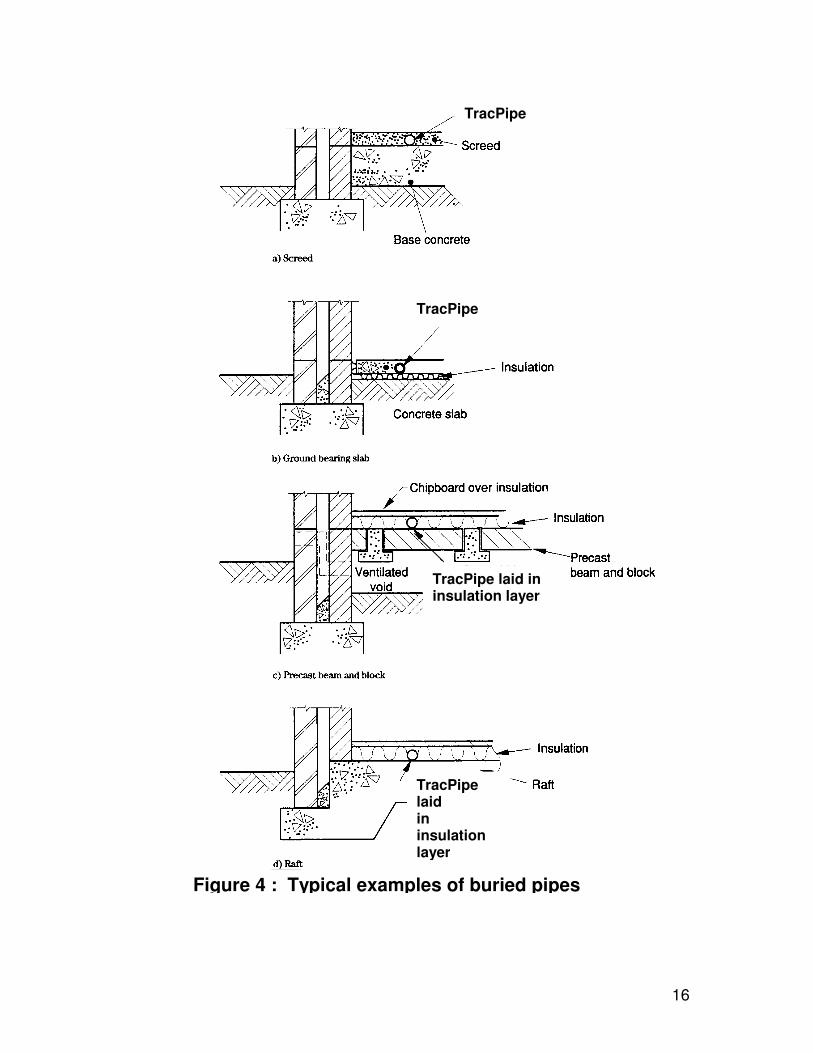
8.4 Pipes laid in concrete floors
8.4.1 TracPipe corrugated stainless steel pipe may be buried directly in concrete floors. Pipe laid in concrete shall be installed in accordance with Figure 4. After piping is laid and prior to pouring screed, the entire run of TracPipe must be examined visually and manually. The installer must closely inspect the cover over the entire length to check for any damage or voids in the yellow plastic cover, which could affect corrosion resistance. Repair any damage by wrapping with tape. Tape wrapping must be done with self-bonding silicone tape TracPipe P/N FGP-915-10H-12, (25 mm wide), or FGP-915-20H12PO, (50 mm wide).
8.4.2 Pipes laid in concrete floors shall be protected against failure caused by movement.
TracPipe is suitable to withstand seismic movement and settlement. TracPipe is fitted with a polyethylene covering material, which is soft yet thick enough to provide movement and resilient enough to support the concrete cover while it is setting.
8.4.3 Pipes passing vertically through solid floors shall take the shortest practicable
route and shall be sleeved (see 8.6).
8.4.4 TracPipe fittings shall not be buried in the structure or below ground. Boxes, with removable plastic covers and suitable for accessing TracPipe fittings within floor screed are available from any Electrical or Hardware Store as conduit junction boxes’.
15
10
TracPipe
TracPipe
TracPipe laid in insulation layer
TracPipe laid in insulation layer
Figure 4 : Typical examples of buried pipes
16
19
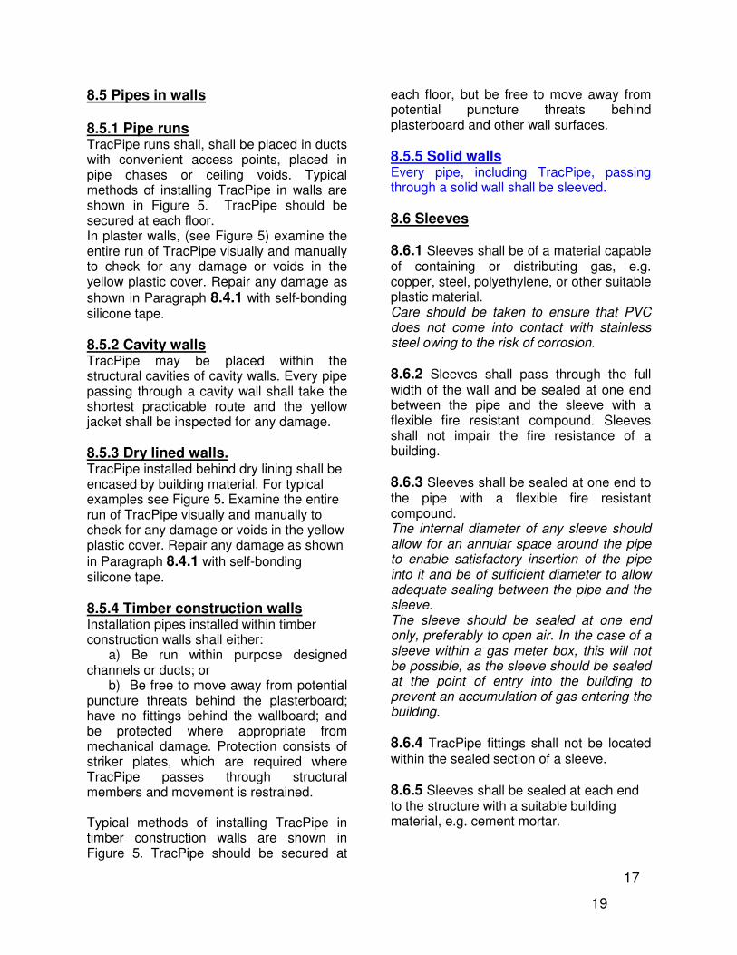
8.5 Pipes in walls 8.5.1 Pipe runs TracPipe runs shall, shall be placed in ducts with convenient access points, placed in pipe chases or ceiling voids. Typical methods of installing TracPipe in walls are shown in Figure 5. TracPipe should be secured at each floor. In plaster walls, (see Figure 5) examine the entire run of TracPipe visually and manually to check for any damage or voids in the yellow plastic cover. Repair any damage as
shown in Paragraph 8.4.1 with self-bonding silicone tape.
8.5.2 Cavity walls TracPipe may be placed within the structural cavities of cavity walls. Every pipe passing through a cavity wall shall take the shortest practicable route and the yellow jacket shall be inspected for any damage.
8.5.3 Dry lined walls. TracPipe installed behind dry lining shall be encased by building material. For typical examples see Figure 5. Examine the entire run of TracPipe visually and manually to check for any damage or voids in the yellow plastic cover. Repair any damage as shown
in Paragraph 8.4.1 with self-bonding silicone tape.
8.5.4 Timber construction walls Installation pipes installed within timber construction walls shall either:
a) Be run within purpose designed channels or ducts; or
b) Be free to move away from potential puncture threats behind the plasterboard; have no fittings behind the wallboard; and be protected where appropriate from mechanical damage. Protection consists of striker plates, which are required where TracPipe passes through structural members and movement is restrained. Typical methods of installing TracPipe in timber construction walls are shown in Figure 5. TracPipe should be secured at
each floor, but be free to move away from potential puncture threats behind plasterboard and other wall surfaces.
8.5.5 Solid walls Every pipe, including TracPipe, passing through a solid wall shall be sleeved.
8.6 Sleeves
8.6.1 Sleeves shall be of a material capable of containing or distributing gas, e.g. copper, steel, polyethylene, or other suitable plastic material. Care should be taken to ensure that PVC does not come into contact with stainless steel owing to the risk of corrosion.
8.6.2 Sleeves shall pass through the full width of the wall and be sealed at one end between the pipe and the sleeve with a flexible fire resistant compound. Sleeves shall not impair the fire resistance of a building.
8.6.3 Sleeves shall be sealed at one end to the pipe with a flexible fire resistant compound. The internal diameter of any sleeve should allow for an annular space around the pipe to enable satisfactory insertion of the pipe into it and be of sufficient diameter to allow adequate sealing between the pipe and the sleeve. The sleeve should be sealed at one end only, preferably to open air. In the case of a sleeve within a gas meter box, this will not be possible, as the sleeve should be sealed at the point of entry into the building to prevent an accumulation of gas entering the building.
8.6.4 TracPipe fittings shall not be located within the sealed section of a sleeve.
8.6.5 Sleeves shall be sealed at each end to the structure with a suitable building material, e.g. cement mortar.
17
19
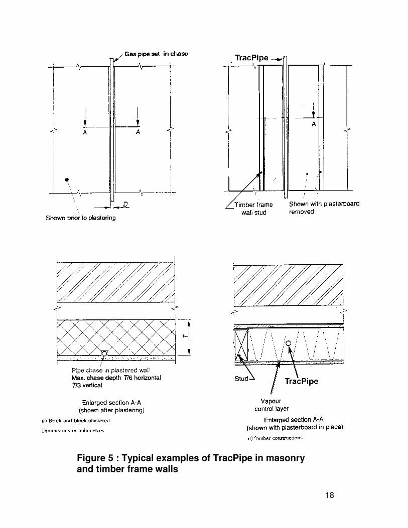
Figure 5 : Typical examples of TracPipe in masonry and timber frame walls
F
18
19
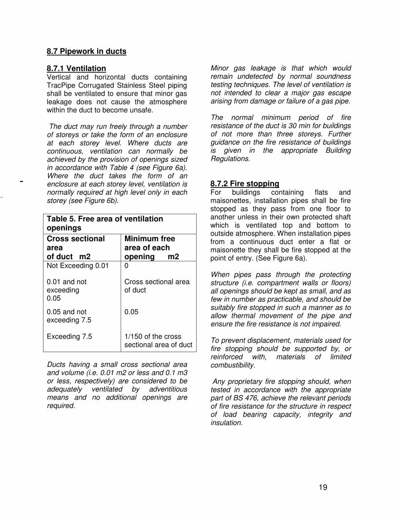
8.7 Pipework in ducts
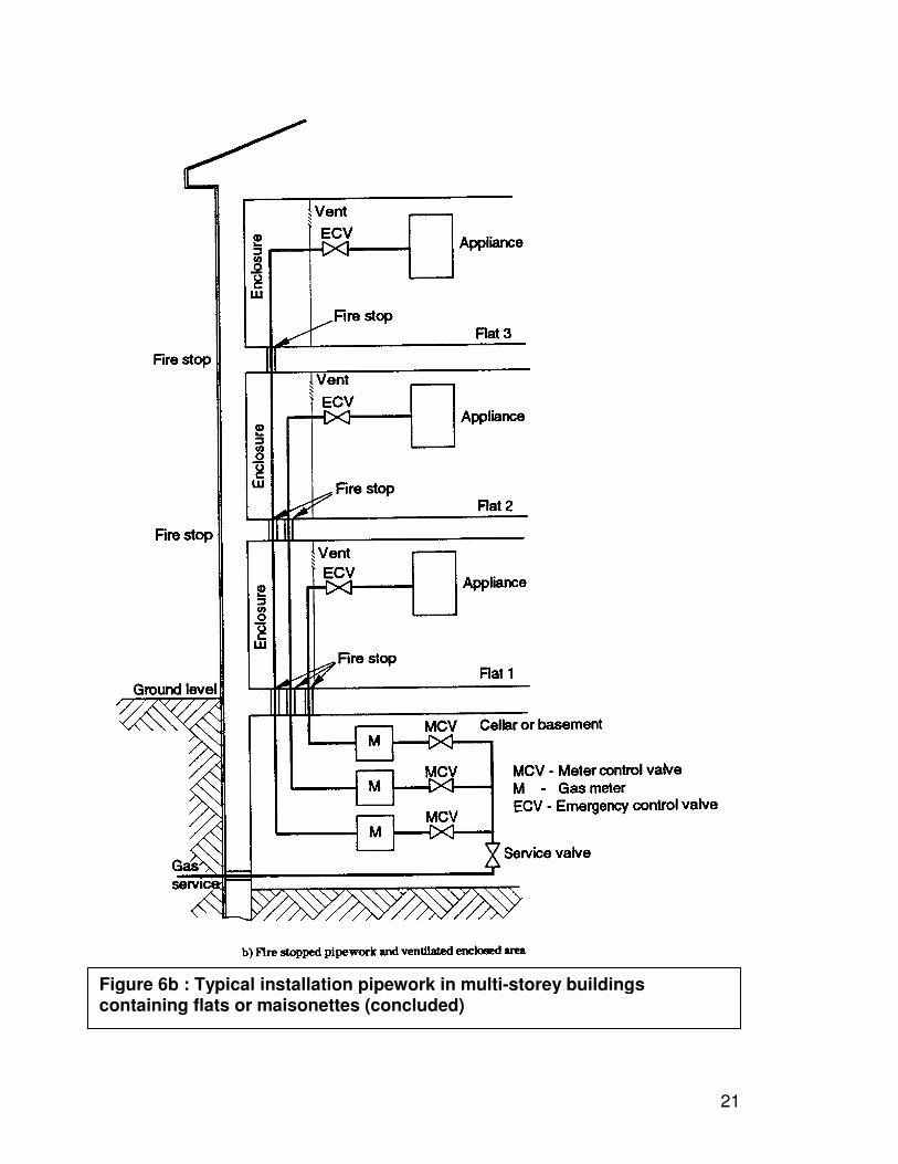
8.7.1 Ventilation Vertical and horizontal ducts containing TracPipe Corrugated Stainless Steel piping shall be ventilated to ensure that minor gas leakage does not cause the atmosphere within the duct to become unsafe. The duct may run freely through a number of storeys or take the form of an enclosure at each storey level. Where ducts are continuous, ventilation can normally be achieved by the provision of openings sized in accordance with Table 4 (see Figure 6a). Where the duct takes the form of an enclosure at each storey level, ventilation is normally required at high level only in each storey (see Figure 6b).
Ducts having a small cross sectional area and volume (i.e. 0.01 m2 or less and 0.1 m3 or less, respectively) are considered to be adequately ventilated by adventitious means and no additional openings are required.
Minor gas leakage is that which would remain undetected by normal soundness testing techniques. The level of ventilation is not intended to clear a major gas escape arising from damage or failure of a gas pipe. The normal minimum period of fire resistance of the duct is 30 min for buildings of not more than three storeys. Further guidance on the fire resistance of buildings is given in the appropriate Building Regulations.
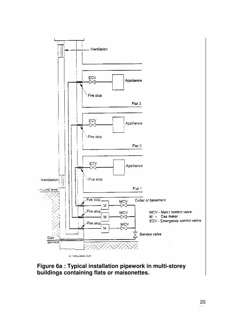
8.7.2 Fire stopping For buildings containing flats and maisonettes, installation pipes shall be fire stopped as they pass from one floor to another unless in their own protected shaft which is ventilated top and bottom to outside atmosphere. When installation pipes from a continuous duct enter a flat or maisonette they shall be fire stopped at the point of entry. (See Figure 6a). When pipes pass through the protecting structure (i.e. compartment walls or floors) all openings should be kept as small, and as few in number as practicable, and should be suitably fire stopped in such a manner as to allow thermal movement of the pipe and ensure the fire resistance is not impaired. To prevent displacement, materials used for fire stopping should be supported by, or reinforced with, materials of limited combustibility. Any proprietary fire stopping should, when tested in accordance with the appropriate part of BS 476, achieve the relevant periods of fire resistance for the structure in respect of load bearing capacity, integrity and insulation.
Table 5. Free area of ventilation openings
Cross sectional area of duct m2
Minimum free area of each opening m2
Not Exceeding 0.01
0
0.01 and not exceeding 0.05
Cross sectional area of duct
0.05 and not exceeding 7.5 Exceeding 7.5
0.05 1/150 of the cross sectional area of duct
21
Figure 6a : Typical installation pipework in multi-storey buildings containing flats or maisonettes.
20
21
Figure 6b : Typical installation pipework in multi-storey buildings containing flats or maisonettes (concluded)
1
8.8 Gas pipework inside a protected shaft containing a stair and/or lift or other protected fire escape route. In addition to the requirements for fire
resistance (see 8.7.1) and fire stopping
(see 8.7.2) any pipe carrying gas installed in, or passing through, a protecting structure shall be of screwed steel or of an all welded steel construction. Neither copper nor corrugated stainless steel, TracPipe, are acceptable inside a protected shaft – containing a fire escape route. However, note that a pipe is not considered to be within a protected shaft if it is contained within a fire resistant duct that is itself ventilated direct to outside atmosphere. TracPipe can then be installed in a stairwell but it must then be enclosed by suitable fire resistant material in a separate duct, which must be ventilated to outside atmosphere if the cross sectional area of the duct exceeds
0.01 square metres, (see 8.7.1).
The requirement given in 8.8 does not normally apply to one or two storey domestic dwellings.
8.9 Pipe Supports and Fittings BS 6891 specifies a maximum interval between pipe supports, for all sizes to 28 mm, of 600 mm for a vertical run and 500 mm for a horizontal run. TracPipe is not annealed after forming to ensure maximum hoop strength and resistance to external damage. As such it has a lower tendency to sag than annealed product. Further, provided fixings are not too close TracPipe has a tendency to deflect away from penetrating objects such as nails, drills and screws. Sound practical judgement should be used, dependent upon the installation. We recommend a maximum spacing of 3.0 metres on vertical runs and
the following for horizontal or inclined runs : 12mm TracPipe – 1.2 m maximum All other sizes – 1.8 m maximum
8.10 Exterior pipework TracPipe is suitable for exterior, exposed use. The yellow polyethylene cover has passed through testing for ultraviolet attack and colour fade. Again the cover should be checked for damage, and repaired if
necessary as outlined in 8.4.1. Further painting and labelling, as with traditional rigid pipe, is not necessary. Any exposed stainless steel should be covered with self
adhesive silicon tape, (see 7.1.6 ). Although it is more common to use polyethylene pipe for exterior underground pipe, TracPipe is suitable, provided the cover and exposed stainless steel are treated as outlined above. Buried pipework in open soil or below vehicular traffic areas shall have at least 375 mm of cover. Buried pipework in or below concrete, which has only pedestrian traffic, shall have at least 40 mm of cover. TracPipe AutoFlare fittings shall not be buried below ground.
8.11 Interrelation with other services
8.11.1 General TracPipe Corrugated Stainless Steel Piping shall be located so that it does not touch metallic fitments, which can give rise to electrolytic corrosion. The polyethylene cover should provide adequate protection where spacing is impracticable. Care is essential when installing gas pipework in buildings containing electrical damp-proof protection systems to prevent accelerated pipe corrosion from occurring.
22
22
8.11.2 Spacing Ideally TracPipe should be spaced at least 25 mm away from electricity supply and distribution cables, and other metallic services. Where spacing requirements are impracticable the polyethylene cover will provide adequate protection.
8.11.3 Electrical services Care shall be taken not to damage any electrical conductor when installing pipework. TracPipe shall not be buried in floors where electrical underfloor heating is installed, unless it has been physically and permanently disconnected.
8.11.4 Main equipotential bonding (cross bonding)
8.11.4.1 All domestic gas installations shall have main equipotential bonding of the gas installation pipework conforming to BS 7671 (IEE Wiring Regulations). The purpose of electrical bonding is to create a zone in which voltage differences, and therefore hazards from electric shocks, are minimized. This is achieved by connecting separate conductive components together with earthing cable or metal pipework. If an electrical fault occurs, either inside or outside of a building, it is possible for stray currents to be transmitted through the gas installation pipework. With a PME (protective multiple earth) system, a small current may pass along the pipework under normal conditions. Therefore, to avoid electric shock, or a spark, which could ignite the gas, it is important to maintain electrical continuity in the pipework at all times.
8.11.4.2 Main equipotential bonding shall be connected: a) on the customer's side of the meter; b) as close as practicable to the meter before any branch in the installation pipework;
c) in a position where it can be visually observed, with a warning label stating 'Safety electrical connection. Do not remove'; d) by a mechanically and electrically sound connection which is not subject to corrosion (i.e. not exposed to the weather). Main equipotential bonding of the gas installation pipework should be a minimum of 10 mm2 cable with green and yellow insulation, construction reference 6491X conforming to BS 6004. For internal meters, for verification purposes bonding connection should be within 600 mm of meter outlet. For meters in outside meter boxes/compartments, the bonding connection should be preferably inside the building and as near as practicable to the point of entry of the installation pipework into the building. Alternatively, the connection may be made within the box/compartment, but it is essential that the bonding cable does not interfere with the integrity of the box/compartment and the sealing of any sleeve. When relocating a meter, an existing main equipotential bond may be satisfactory as found, or it may need to be either lengthened or shortened or, in some cases, completely re-run. The bond connection is
satisfactory if the conditions of 8.11.4.1 are met.
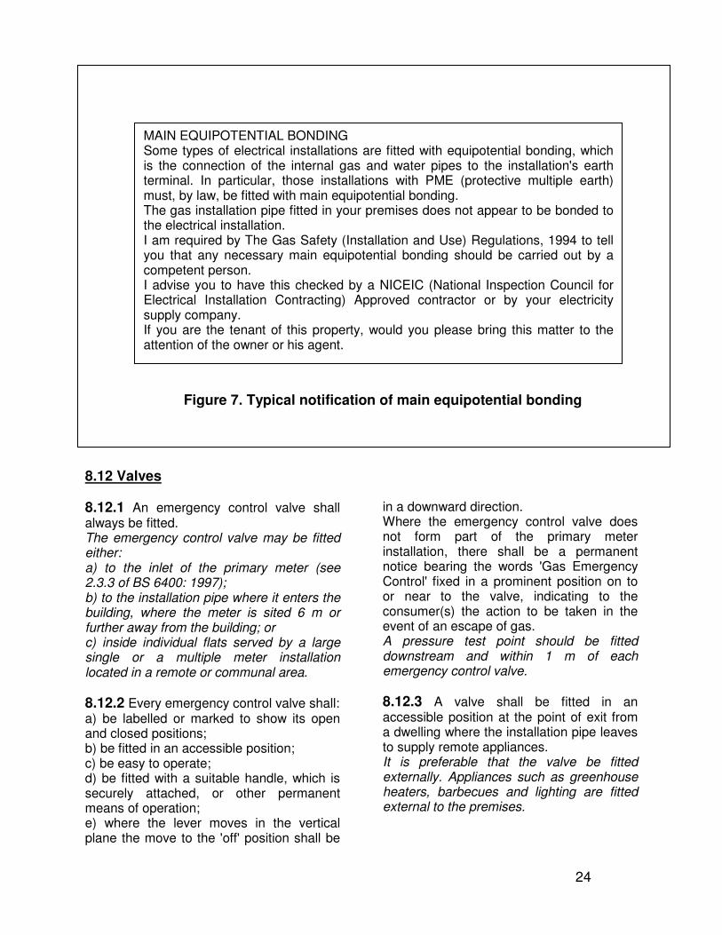
8.11.4.3 When a gas installation pipe is connected to a primary meter installation, the installer of the installation pipe shall, in the case where main equipotential bonding may be necessary, inform the responsible person that such bonding should be carried out by a competent person. For new gas installations the responsibility for the main equipotential bond lies with the installer to preferably carry out the bonding directly, where competent to do so, or, alternatively, pass notification (e.g. a letter or card, see Figure 7) to the responsible person (e.g. house owner, tenant, landlord or builder).
23
22
Figure 7. Typical notification of main equipotential bonding
8.12 Valves
8.12.1 An emergency control valve shall always be fitted. The emergency control valve may be fitted either: a) to the inlet of the primary meter (see 2.3.3 of BS 6400: 1997); b) to the installation pipe where it enters the building, where the meter is sited 6 m or further away from the building; or c) inside individual flats served by a large single or a multiple meter installation located in a remote or communal area.
8.12.2 Every emergency control valve shall: a) be labelled or marked to show its open and closed positions; b) be fitted in an accessible position; c) be easy to operate; d) be fitted with a suitable handle, which is securely attached, or other permanent means of operation; e) where the lever moves in the vertical plane the move to the 'off' position shall be
in a downward direction. Where the emergency control valve does not form part of the primary meter installation, there shall be a permanent notice bearing the words 'Gas Emergency Control' fixed in a prominent position on to or near to the valve, indicating to the consumer(s) the action to be taken in the event of an escape of gas. A pressure test point should be fitted downstream and within 1 m of each emergency control valve.
8.12.3 A valve shall be fitted in an accessible position at the point of exit from a dwelling where the installation pipe leaves to supply remote appliances. It is preferable that the valve be fitted externally. Appliances such as greenhouse heaters, barbecues and lighting are fitted external to the premises.
MAIN EQUIPOTENTIAL BONDING Some types of electrical installations are fitted with equipotential bonding, which is the connection of the internal gas and water pipes to the installation's earth terminal. In particular, those installations with PME (protective multiple earth) must, by law, be fitted with main equipotential bonding. The gas installation pipe fitted in your premises does not appear to be bonded to the electrical installation. I am required by The Gas Safety (Installation and Use) Regulations, 1994 to tell you that any necessary main equipotential bonding should be carried out by a competent person. I advise you to have this checked by a NICEIC (National Inspection Council for Electrical Installation Contracting) Approved contractor or by your electricity supply company. If you are the tenant of this property, would you please bring this matter to the attention of the owner or his agent.
24
25
9 CORROSION
9.1 General 9.1.1 A gas pipe or pipe fitting shall not be installed in a position where it is likely to be exposed to a corrosive environment. Gas pipes or fittings that are considered to be at risk shall either be manufactured from materials that are inherently resistant to corrosion or shall be protected against corrosion. TracPipe is supplied with a polyethylene cover, which provides suitable corrosion resistance for a majority of installations. Care must be taken when assembling AutoFlare fittings to assure that no stainless steel pipe is visible. Exposed stainless steel behind the fitting nut shall be wrapped with self-bonding silicone tape TracPipe P/N FGP-915-10H-12, (25 mm wide), or FGP-915-20H12PO, (50 mm wide). This will reduce the possibility of later corrosive attack.
9.1.2 Pipework in fireplace openings Do not install TracPipe in the openings of all-fuel fireplaces. Soot and debris can be highly corrosive. TracPipe feeding this type of fireplace must be terminated outside of the firebox and the final fit up made with suitably protected pipe. The flexibility of TracPipe can be utilized to carry out this type of installation.
9.1.3 Assembled pipework shall be tested
for soundness in accordance with clause 10 before any additional protection against corrosion is applied on site.
9.2 Buried pipework
9.2.1 Internal environment 9.2.1.1 Pipework that is buried in a solid floor or wall shall be factory sheathed, or
protected on site by wrapping or with suitable bituminous paint protection. The entire section of pipe and fittings to be buried shall be protected. TracPipe cover or wrapping shall be examined for cuts or other defects and made good prior to use. Any portions of exposed stainless steel or cut cover shall be wrapped with self-bonding silicone tape TracPipe P/N FGP-915-10H-12, (25 mm wide), or FGP-915-20H12PO, (50 mm wide). This will reduce the possibility of later corrosive attack. Protective measures are applied as a precaution against electrolytic and/or chemical corrosion.
9.2.1.2 If TracPipe is to be used for installation piping to be buried in magnesium-oxy-chloride cement or magnesite flooring, please consult us before installation.
9.2.2 External environment 9.2.2.1 TracPipe is suitable for external applications, including burial. The integrity of the polyethylene cover should be checked and rectified if necessary. (See
8.4.1). Fittings shall not be buried. Further information on the correct procedures for laying buried pipes is given in the Institution of Gas Engineers and Managers Recommendations IGE/TD/4.
9.2.2.2 TracPipe run above ground is protected from corrosion by the polyethylene cover. Ensure any exposed stainless steel is suitably covered (see
7.1.6 and 8.4.1).
29
10 TESTING FOR GAS TIGHTNESS, AND PURGING. Domestic installations with a pipework size in excess of TracPipe DN28, or installations greater in volume than the typical domestic installation, or with a gas meter larger in volume than a U6/G4/E6, should be tested to the requirements of the Institution of Gas Engineers and Managers (IGEM) document IGE/UP/1 or IGE/UP/1A – Soundness Testing & Purging of Industrial and Commercial Gas Installations. Domestic installations, apart from those above, should be tested and purged in accordance with IGE/UP/1B – Tightness testing and purging of domestic sized Natural gas installations. For propane and butane installations testing for soundness should be in accordance with the LP Gas Association (LPGA) Technical Memorandum TM62 – Gas soundness testing of LPG service pipework, installation pipework and appliances. It is important to note that some leak detection fluids (LDF) contain compounds that can be corrosive, either to stainless steel or to brass. Should the use of LDF’s be necessary the operator must ensure that all traces are removed by washing with clean water. Household or ‘washing up’ liquid should NOT be used as leak detection fluid, as the high chloride content is corrosive to metals. TracPipe self adhesive silicon tape should be used to cover exposed stainless steel; it is essential that this is not applied until the pipework has been tested and deemed to be gas tight, (and any traces of LDF, if used, washed away and the pipe and fitting dried). The tape should run onto the back nut, leaving sufficient space to apply an earthing connection to the back nut or fitting body.
11. DAMAGE AND REPAIR.
11.1 General. TracPipe, whilst very light has considerable hoop strength and will generally resist external damage better than copper. Further, provided it is not fixed too closely TracPipe has the natural ability to deflect away from nails, screws, drills and other implements of puncture. If the tubing is damaged, refer to the following sections to determine the severity of damage and, if necessary, the method of repair.
11.2 Assessment. Repairs to the cover can be effected by the use of self-adhesive silicon tape, as described earlier (see 8.4.1). No repairs or replacement of the tubing is necessary if the tubing is only slightly dented due to impact or crushing where the outside diameter is reduced by under 1/3. The tubing must be replaced under the following circumstances :
A. The tubing has been significantly crushed or dented, where the outside diameter is reduced by more than 1/3.
B. The tubing has been damaged by puncture of any kind i.e. nails, screws, drill bits, etc.
C. The tubing has been bent beyond its minimum bend radius so that a crease or kink remains.
11.3 Repair. A line splice can be made using two straight AutoFlare fittings and a female malleable iron socket, or by using a TracPipe coupling. However, if the tubing run is short and easily accessible, the preferred repair is to replace the entire length. A tubing run can often be replaced faster than repairing the damaged section with a splice and this does not add any additional fitting joints into the system. The AutoFlare fittings can be reattached to the new tubing run.
26
30
ANNEX A (Normative)
A.1 Installation procedures The installation pipework should be installed and tested in accordance with SANS 10087/1 or BS 6891 or the Institution of Gas Engineers publications IGE/UP/2, IGE/UP/1, IGE/UP/1A or IGE/UP/1B as appropriate, supplemented by the manufacturer’s instructions. When designing and planning the installation, consideration should be given to the possibility of restricted access on site and the forces and torques required for assembly, particularly for the larger diameters.
A.2 Compatible products Corrugated pipe from a particular manufacturer should be assembled directly to fittings supplied or specified by the same manufacturer and should not be directly assembled to fittings from other sources.
A.3 Pipe sizes Sizing of installation pipework should be carried out in accordance with the principles given in clause 4 of BS 6891:1988 and in section 4 of the Institution of Gas Engineers publication IGE/UP/2, as appropriate.
A.4 Seals Care should be taken to avoid damaging seals. Any damaged seals should be discarded.
A.5 Pipe supports and appliance connection Corrugated stainless steel semi-rigid pipe to BS 7838 should not be used where during installation, or subsequent to installation, it can be subjected to repeated bending. Corrugated stainless steel semi-rigid pipe to BS 7838 is an alternative to traditional rigid pipe systems.
Installation pipework should be adequately supported in accordance with the requirements of SANS 10087/1 or BS 6891 for sizes up to 28 mm, and the manufacturers instructions for larger sizes. A movable appliance (e.g. cooker, tumble dryer) should not be connected directly to corrugated stainless steel piping. Connection should be made in accordance with SANS 10087/1 or BS 6172, BS 6173 or BS 7624 as appropriate. Overhead heaters are not considered as moveable appliances and TracPipe can be connected directly to these units. The length of unsupported corrugated pipe connected directly to any fixed appliance should not exceed 500 mm. Where the final connection is made indirectly by using a length of rigid pipe, the end fittings or capillary adaptor should be permanently fixed. If the appliance is normally moved for servicing, an isolation valve and a union coupling or other suitable means of disconnection should be fitted at the appliance inlet. During assembly or disassembly, manifolds if used, should be adequately supported by wrenches or other means, to avoid excessive strain on fittings or attached pipework.
A.6 Connections to copper pipe Soldering to copper pipe is not recommended. Any soldering necessary for connection to copper pipe should be carried out, and the soldered component cleaned of flux, before assembly to the corrugated pipe. It is important that stainless steel is not contaminated in any way with flux.
27
31
ANNEX B (Normative)
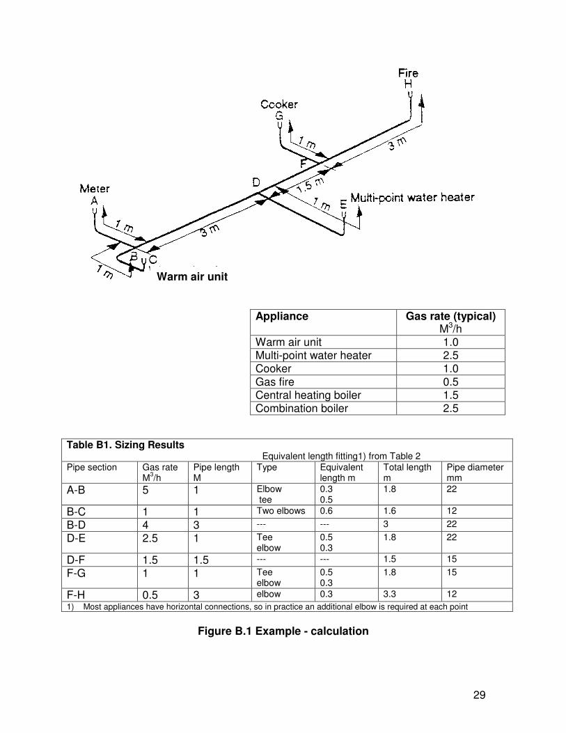
GUIDE TO SIZING GAS SUPPLIES. When deciding on the correct size of gas pipes for an internal installation, it is recommended practice to allow a maximum pressure loss of 1 mbar between the meter outlet and the appliance connection points. The size of the pipe selected should be of sufficient diameter to supply all the appliances on the installation when they are used at the maximum gas rate. Figure B.1 gives an example of a typical TracPipe Stainless Steel Piping installation showing the lengths of pipes and the gas rates of the appliances. The pipes have been sized using Tables 1 & 2 and the results are shown in table B.1. When sizing pipes, it is essential that consideration is given to the permissible pressure loss in each section of' the installation. For example, the pressure loss between A and H in figure B.1 should not exceed 1 mbar. A to H is made up of four sections of pipe, A-B, B-D, D-F and F-H. Each section carries a different gas rate and needs to be sized separately If A to H is to have a pressure loss of not more than I mbar, then the pressure losses in each of the four sections should be approximately 0.25 mbar. So A-B, B-D, D-F and F-H should each be sized to give a pressure loss of approximately 0.25 mbar. The table of discharges in a straight horizontal pipe given in Table 1 only
allows for pressure losses of 1 mbar. However pressure loss is proportional to length, so if the pipe size selected in Table 1 is four times longer than required, the pressure loss on the actual length will be 0.25 mbar. Example Considering length D-F as given in figure B.1 : D-F has a length of 1.5 m and is to carry a gas rate of 1.5 m3/h; it should have a pressure loss of 0.25 mbar maximum. However, a pressure loss of 0.25 mbar in a length of 1.5 m equals (4 × 0.25) = I mbar in (4 × 1.5 m)= 6 m. In Table 1, look up the column under 6m, for a discharge of 1.5 m3/h and find: 12 mm = 1.0 m3/h 15 mm = 1.9 m3/h The first size, 12 mm, would give a lower flow rate than is required. The larger size, 15 mm, would carry the 1.5 m3/h of gas with little pressure loss and could allow for appliances to be added to the installation at a later date, if required. This is the size to be used. NOTE. The same calculations can be used for sizing supplies for liquefied petroleum gas (LPG), as this requires smaller diameter pipes and operates at a higher pressure. The property could be converted to natural gas in the future and no problems would be found with the pipe sizes.
28
32
Appliance Gas rate (typical) M3/h
Warm air unit 1.0 Multi-point water heater 2.5 Cooker 1.0
Gas fire 0.5 Central heating boiler 1.5 Combination boiler 2.5
Table B1. Sizing Results Equivalent length fitting1) from Table 2
Pipe section
Gas rate M
3/h
Pipe length M
Type Equivalent length m
Total length m
Pipe diameter mm
A-B 5 1 Elbow tee
0.3 0.5
1.8 22
B-C 1 1 Two elbows 0.6 1.6 12
B-D 4 3 --- --- 3 22
D-E 2.5 1 Tee elbow
0.5 0.3
1.8 22
D-F 1.5 1.5 --- --- 1.5 15
F-G 1 1 Tee elbow
0.5 0.3
1.8 15
F-H 0.5 3 elbow 0.3 3.3 12
1) Most appliances have horizontal connections, so in practice an additional elbow is required at each point
Figure B.1 Example - calculation
Warm air unit
29
33
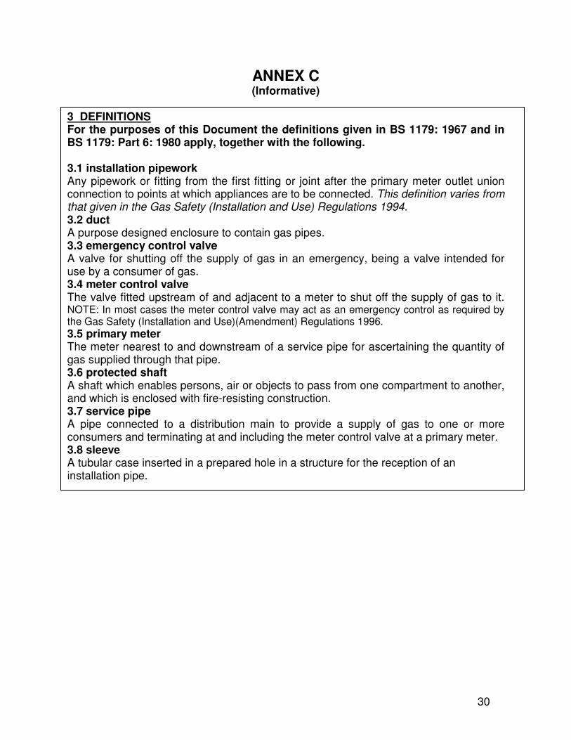
ANNEX C (Informative)
3 DEFINITIONS For the purposes of this Document the definitions given in BS 1179: 1967 and in BS 1179: Part 6: 1980 apply, together with the following. 3.1 installation pipework Any pipework or fitting from the first fitting or joint after the primary meter outlet union connection to points at which appliances are to be connected. This definition varies from that given in the Gas Safety (Installation and Use) Regulations 1994. 3.2 duct A purpose designed enclosure to contain gas pipes. 3.3 emergency control valve A valve for shutting off the supply of gas in an emergency, being a valve intended for use by a consumer of gas. 3.4 meter control valve The valve fitted upstream of and adjacent to a meter to shut off the supply of gas to it. NOTE: In most cases the meter control valve may act as an emergency control as required by the Gas Safety (Installation and Use)(Amendment) Regulations 1996.
3.5 primary meter The meter nearest to and downstream of a service pipe for ascertaining the quantity of gas supplied through that pipe. 3.6 protected shaft A shaft which enables persons, air or objects to pass from one compartment to another, and which is enclosed with fire-resisting construction. 3.7 service pipe A pipe connected to a distribution main to provide a supply of gas to one or more consumers and terminating at and including the meter control valve at a primary meter. 3.8 sleeve A tubular case inserted in a prepared hole in a structure for the reception of an installation pipe.
30
35
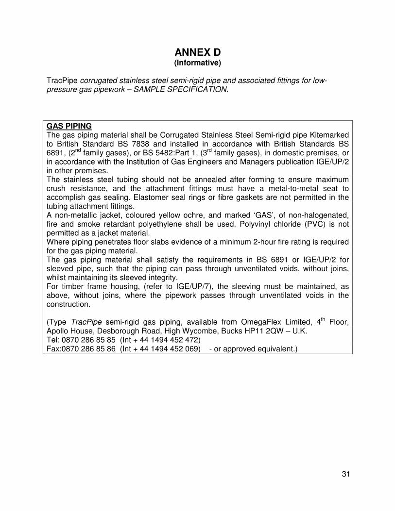
ANNEX D (Informative)
TracPipe corrugated stainless steel semi-rigid pipe and associated fittings for low-pressure gas pipework – SAMPLE SPECIFICATION.
GAS PIPING The gas piping material shall be Corrugated Stainless Steel Semi-rigid pipe Kitemarked to British Standard BS 7838 and installed in accordance with British Standards BS 6891, (2nd family gases), or BS 5482:Part 1, (3rd family gases), in domestic premises, or in accordance with the Institution of Gas Engineers and Managers publication IGE/UP/2 in other premises. The stainless steel tubing should not be annealed after forming to ensure maximum crush resistance, and the attachment fittings must have a metal-to-metal seat to accomplish gas sealing. Elastomer seal rings or fibre gaskets are not permitted in the tubing attachment fittings. A non-metallic jacket, coloured yellow ochre, and marked ‘GAS’, of non-halogenated, fire and smoke retardant polyethylene shall be used. Polyvinyl chloride (PVC) is not permitted as a jacket material. Where piping penetrates floor slabs evidence of a minimum 2-hour fire rating is required for the gas piping material. The gas piping material shall satisfy the requirements in BS 6891 or IGE/UP/2 for sleeved pipe, such that the piping can pass through unventilated voids, without joins, whilst maintaining its sleeved integrity. For timber frame housing, (refer to IGE/UP/7), the sleeving must be maintained, as above, without joins, where the pipework passes through unventilated voids in the construction. (Type TracPipe semi-rigid gas piping, available from OmegaFlex Limited, 4th Floor, Apollo House, Desborough Road, High Wycombe, Bucks HP11 2QW – U.K. Tel: 0870 286 85 85 (Int + 44 1494 452 472) Fax:0870 286 85 86 (Int + 44 1494 452 069) - or approved equivalent.)
31
34
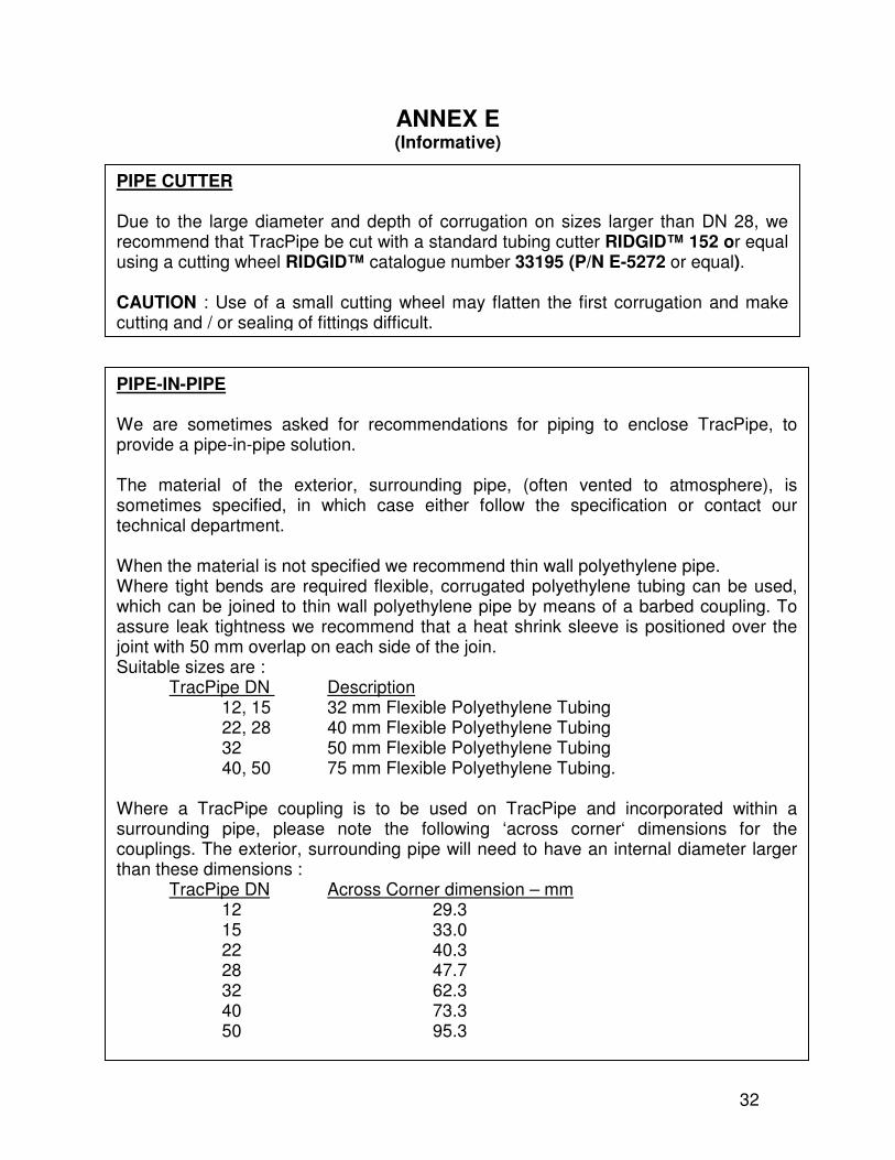
ANNEX E (Informative)
PIPE CUTTER Due to the large diameter and depth of corrugation on sizes larger than DN 28, we recommend that TracPipe be cut with a standard tubing cutter RIDGID™ 152 or equal using a cutting wheel RIDGID™ catalogue number 33195 (P/N E-5272 or equal). CAUTION : Use of a small cutting wheel may flatten the first corrugation and make cutting and / or sealing of fittings difficult.
PIPE-IN-PIPE We are sometimes asked for recommendations for piping to enclose TracPipe, to provide a pipe-in-pipe solution. The material of the exterior, surrounding pipe, (often vented to atmosphere), is sometimes specified, in which case either follow the specification or contact our technical department. When the material is not specified we recommend thin wall polyethylene pipe. Where tight bends are required flexible, corrugated polyethylene tubing can be used, which can be joined to thin wall polyethylene pipe by means of a barbed coupling. To assure leak tightness we recommend that a heat shrink sleeve is positioned over the joint with 50 mm overlap on each side of the join. Suitable sizes are : TracPipe DN Description 12, 15 32 mm Flexible Polyethylene Tubing 22, 28 40 mm Flexible Polyethylene Tubing
32 50 mm Flexible Polyethylene Tubing 40, 50 75 mm Flexible Polyethylene Tubing.
Where a TracPipe coupling is to be used on TracPipe and incorporated within a surrounding pipe, please note the following ‘across corner‘ dimensions for the couplings. The exterior, surrounding pipe will need to have an internal diameter larger than these dimensions : TracPipe DN Across Corner dimension – mm
12 29.3 15 33.0 22 40.3 28 47.7 32 62.3 40 73.3 50 95.3
32
34
ANNEX F (Informative)
TracPipe stainless steel semi-rigid gas piping to BS 7838 Statement on the installation of gas pipes in false ceilings and suspended or floating
floors.
There exists confusion between Consulting Engineers, Contractors and CORGI registered installers about where and how gas piping can be installed in false ceilings and floating/ suspended floors – associated with the requirements for ventilation. For example, domestically, it was custom and practice to install gas piping through joists at intermediate level, without providing additional ventilation. This was probably fine when floorboards were used, as the gaps in the floorboards would have provided ventilation of the underfloor space. Modern techniques of constructing dwellings means large sheets of boarding replace individual floorboards and these are often grooved for a tight fit. As a result ventilation has been reduced, creating large cavities that could prove to be a hazard in the event of a minor gas leakage, undetected by normal testing means. The Gas Safety (Installation and Use) Regulations 1998 has an Approved Code of Practice, drawn up by the Health and Safety Commission¹ and effective from 31st October 1998, which gives practical advice. Regulation 19(2) states:
(2) No person shall install any installation pipework so as to pass through a wall or a floor or standing of solid construction (whether or not it contains any cavity) from one side to another unless –
(a) any part of the pipe within such wall, floor or standing as the case may be takes the shortest practicable route; and
(b) adequate means are provided to prevent, so far as is reasonably practicable, any escape of gas from the pipework passing through the wall, floor or standing from entering any cavity in the wall, floor or standing.
The Guidance states: SANA 10087 Part 1 addresses the potential risk of gas leaking from pipework within a cavity in a wall, floor or standing; such leakage may be difficult to detect and readily lead to the accumulation of an explosive gas/air mixture in the cavity, presenting a considerable hazard to building occupants and others. The protective measures required may include enclosing that part of the pipe which passes through the wall, floor or standing in a gastight sleeve which is itself ventilated to a safe position, preferably to open air. This approach also provides some protection against mechanical damage to pipework, arising from structural movement (see also regulation 19(5); any gap between the pipe and sleeve should be sealed (with flexible sealant), but at one end only so as to ensure any leak cannot accumulate in the gap space.
33
34
BS EN 1775:1998 Gas supply – Gas pipework for buildings – Maximum operating pressure up to and including 5 bar – Functional recommendations states, in clause 2.4.2.1: If possible, the gas pipework in buildings shall be located in ventilated spaces. The ventilation of spaces shall be adequate to dilute safely any small gas leak. Where it is not possible to achieve adequate ventilation, other solutions shall be applied, e.g. ventilated sleeves or ducts, all welded pipes or the filling of the space with inert materials. Particular attention shall be paid to the ventilation of spaces at low levels where gases heavier than air are being distributed. The Institution of Gas Engineers Utilization Procedures IGE/UP/2 - Gas installation pipework, boosters and compressors on industrial and commercial premises states, in clause 10.4 unventilated ducts and voids: Pipework shall not be installed in an unventilated duct or void, unless:
(a) The pipework is sleeved continuously through the unventilated duct or void, with the sleeve ventilated at one or both ends into a safe place or
(b) The unventilated duct or void is filled with a crushed inert infill to reduce to a minimum the volume of any gas which may accumulate. The infill material should be of a dry, chemically neutral and fire resistant nature, for example crushed slate chippings or dry washed sand.
TracPipe is a continuously welded stainless steel semi-rigid gas pipe, BSI Kitemarked to BS 7838, intended for use as installation pipework for the supply of 1st, 2nd and 3rd family gases, at working pressures to 75 mbar. It also has a cover, or sleeve², for the protection of the outer surface of the corrugated pipe against external corrosion and mechanical damage. TracPipe is, in effect, a sleeved pipe, which can pass through unventilated ceilings or floors, providing the route is the shortest practicable, the cover is maintained and provided the ends of the sleeve are themselves in a ventilated area. TracPipe could for instance run from a gas meter, (ventilated to atmosphere), through an unventilated false ceiling, to a gas fire. At the gas fire the sleeve on the TracPipe ends, but the room is ventilated. Any minor gas leakage in the TracPipe, undetected by normal testing means, would be conducted along the inside of the cover to the extremities of the sleeve. We have tested TracPipe’s cover from 20 mbar to 2 bar to demonstrate that it performs satisfactorily as a sleeve, throughout this pressure range. As ever, independent third-party confirmation gives greater comfort to users than merely a manufacturer’s view, and we sought this through BSI. Their test demonstrates that there is a free passage for gas flow between the stainless steel pipe and the outer sleeve on TracPipe.
34
Five practical points to note:
1. Where TracPipe passes through walls we still recommend additional sleeving, as with traditional rigid copper and steel pipework, suitably fire stopped at one end with a flexible (non-setting) fire resistant material.
2. At the meter box TracPipe should still pass through the sleeving provided for
copper or steel, again sealed within the box. 3. What about damage to the cover, which would affect its properties as a sleeve?
Where the TracPipe is visible during installation, a repair to any damaged cover can be made using our yellow part cured silicon rubber tape – as for TracPipe being used in concrete floors. Where TracPipe would not be visible during installation, for instance in threading TracPipe under floors when the floor is already laid, a belt and braces approach is best, either by using TracPipe inside a flexible polyethylene conduit, or through waste- or soil-pipe which runs through the cavity, opening into ventilated areas.
4. TracPipe must not be joined or teed in an unventilated space, unless the cross
sectional area or volume meet the minimum stated in Table 4 of BS 6891:1998, (CORGI Essential Gas Safety table 17), for Nil ventilation.
5. Where the sleeve feature of TracPipe is used through unventilated ceilings
or floors cavities, the yellow part-cured silicon tape should only be applied at one end of the run, such that the sleeve can ventilate into a safe area. Ideally the tape should be at the end at most at risk to external corrosion, e.g. in kitchen areas, where bleach may come into contact with the TracPipe.
Notes:
1. The Health and Safety Commission drew up the Approved Code of Practice in consultation with representatives of the Confederation of British Industry, the Trade Union Congress, local authorities, government departments, consumer organisations and the Health and Safety Executive (HSE).
2. ‘Sleeve’ is defined in BS 6891 as – A tubular case inserted in a prepared hole in a structure for the reception of an installation pipe. Further, ‘sleeves shall be made of a material capable of containing or distributing gas, e.g. copper, steel, polyethylene, polyvinyl chloride (PVC), or other suitable plastics material. (However, PVC should not come into contact with stainless steel owing to the risk of corrosion.
3. ‘Duct’ is defined in BS 6891 as – A purpose designed enclosure to contain gas pipes.
35