Embed Size (px)
Citation preview

Journal of The Electrochemical Society, 164 (13) A3285-A3291 (2017) A3285
Tracking Internal Temperature and Structural Dynamics duringNail Penetration of Lithium-Ion CellsDonal P. Finegan,a,b Bernhard Tjaden,a Thomas M. M. Heenan,a,∗ Rhodri Jervis,aMarco Di Michiel,c Alexander Rack,c Gareth Hinds,d Dan J. L. Brett,a and Paul R. Shearinga,z
aElectrochemical Innovation Lab, Department of Chemical Engineering, University College London, London WC1E7JE, United KingdombTransportation and Hydrogen Systems Center, National Renewable Energy Laboratory, Golden, Colorado 80401, USAcESRF The European Synchrotron, 38000 Grenoble, FrancedNational Physical Laboratory, Teddington, Middlesex TW11 0LW, United Kingdom
Mechanical abuse of lithium-ion batteries is widely used during testing to induce thermal runaway, characterize associated risks, andexpose cell and module vulnerabilities. However, the repeatability of puncture or ‘nail penetration’ tests is a key issue as there is oftena high degree of variability in the resulting thermal runaway process. In this work, the failure mechanisms of 18650 cells puncturedat different locations and orientations are characterized with respect to their internal structural degradation, and both their internaland surface temperature, all of which are monitored in real time. The initiation and propagation of thermal runaway is visualizedvia high-speed synchrotron X-ray radiography at 2000 frames per second, and the surface and internal temperatures are recorded viainfrared imaging and a thermocouple embedded in the tip of the penetrating nail, respectively. The influence of the nail, as well ashow and where it penetrates the cell, on the initiation and propagation of thermal runaway is described and the suitability of this testmethod for representing in-field failures is discussed.© The Author(s) 2017. Published by ECS. This is an open access article distributed under the terms of the Creative CommonsAttribution 4.0 License (CC BY, http://creativecommons.org/licenses/by/4.0/), which permits unrestricted reuse of the work in anymedium, provided the original work is properly cited. [DOI: 10.1149/2.1501713jes] All rights reserved.
Manuscript submitted September 5, 2017; revised manuscript received October 12, 2017. Published October 31, 2017.
Abuse tests of Li-ion batteries are applied to determine the risksassociated with failure of a particular cell design. Examples of risksthat are of interest to understand include: quantity and rate of heat andgas generation, maximum temperatures reached, how the generatedheat is dissipated, and whether projectiles are produced. Carryingout an abuse test that is fully representative of in-field failures ischallenging. Mechanical abuse is the most common method used tosimulate in-field failures and is of particular interest to the automotivesector where crash and impact tests compromise the safety of utilizedcells. Of these, the most common technique used to induce failurewithin cells and battery packs is via penetration of the cell with asharp object such as a nail during so-called ‘nail penetration’ tests.When the positive and negative electrodes of a cell are connected bya material with low electrical resistance, the cell rapidly dischargeswith a high rate of Joule and entropic heat generation. When a criticaltemperature is exceeded locally, and if there is a sufficient amountof electrolyte, a series of exothermic reactions initiate and propagatethroughout the cell in a process known as ‘thermal runaway’.1–6
In-field puncture-induced failures incur a high degree of variability,which arises from difficulties in controlling parameters such as theinternal architecture of the cell, the size, shape, electrical and thermalproperties of the puncturing object, as well as the depth and rate atwhich the cell is punctured. When attempting to replicate a scenario inwhich a cell undergoes an internal short circuit, the nail penetration testis unsuitable due to it being inherently intrusive, spreading the shortcircuit across a large area and multiple layers, and introducing a heatsink at the region of initiation. For these reasons, the nail penetrationtest is not considered to be a suitable technique for reproduciblyinducing in-field failures or worst case scenarios. Inducing an on-demand local failure within the cell that is representative of an in-field failure poses a great challenge.7 Mechanical abuse using bluntobjects can also lead to internal short-circuiting. For example, whenmechanical failure of the electrode assembly occurs due to appliedtensile strain, electrically conducting layers from the positive andnegative electrode can make contact, causing an internal short circuit.8
Alternative methods for inducing internal short circuits by implantingdevices during manufacturing have previously been described,8,9 buthave not yet been accepted as standard test methods.
∗Electrochemical Society Student Member.zE-mail: [email protected]
Numerous thermal, electrochemical and mechanical models havebeen developed to predict the response of internal architectures ofcommercial cells to mechanical deformation,10–13 but to date thesehave not been validated through direct observation of internal defor-mations during mechanically-induced thermal runaway. Maleki andHoward14 reported that a short circuit near the edge of the electrodeassembly results in a greater temperature rise locally due to the heat be-ing dissipated primarily in one direction, a study which was supportedby surface temperature measurements and post-mortem inspection ofthe cell. Empirical results that elucidate the internal structural andthermal behavior are required to connect internal phenomena with ex-ternal measurements and to validate multi-physics models.11,12,15,16 Tounderstand the variation of failure mechanisms in response to differentabuse conditions, a spatio-temporal description of thermal runawayresulting from each scenario is needed. High-speed X-ray computedtomography (CT) and radiography have been used in previous studiesto visualize the internal breakdown and ejection of active materialsfollowing thermal runaway induced via thermal abuse,17 electricalovercharge18 and internal short-circuiting.8 Failures induced via in-trusive mechanical methods are expected to deviate most significantlyfrom other in-field failures, in particular internal short-circuiting,which nail penetration is sometimes used to simulate.
In this work, visualization via high-speed X-ray imaging is used todescribe the variation of 18650 cell behavior during nail penetrationtests, providing insight into mechanisms of internal structural break-down of cells. The propagation of thermal runaway from the point ofinitiation is captured using high-speed X-ray imaging at 2000 framesper second (fps), and a combined thermal mapping approach of in-frared thermal imaging and internal temperature measurement, viaa modified nail with an embedded thermocouple at its tip,19 is usedto describe the thermal response of the cells. The variability of thethermal and internal structural behavior during nail penetration testsat different locations and orientations of 18650 cells is elucidated.
Experimental
Smart-nail design.—A custom made stainless steel 314 nail withan integrated rapid response insulated K-type thermocouple, that hada diameter of 0.5 mm and an operating range from −100◦C to 800◦C(Product 406–534, TC-direct, UK) (Figure 1a), was used to measurethe temperature at the tip of the nail during the tests. This designwas inspired by the “smart-nail” described by Hatchard et al.19 but
) unless CC License in place (see abstract). ecsdl.org/site/terms_use address. Redistribution subject to ECS terms of use (see 192.174.37.50Downloaded on 2017-12-06 to IP

A3286 Journal of The Electrochemical Society, 164 (13) A3285-A3291 (2017)
Figure 1. (a) Illustration showing a sectioned view of the stainless steel nailwith an integrated thermocouple at its tip. The nail consisted of two compo-nents, the shaft and the tip. (b) Magnified view of the tip section showing theplacement of the thermocouple just beneath the surface of the nail at a slightlyoffset position from the center of the sharpened tip. The tip section was forcedinto the shaft during assembly.
with some modifications. A 60 mm long stainless steel tube with anexternal diameter of 4 mm and an internal diameter of 2 mm wasused as the shaft of the nail. A stainless steel tip (Figure 1b) wassharpened and shaped on a lathe. A 1 mm diameter bore was drilled inthe tip to just beneath the front surface; thereafter a 0.5 mm diameterhole, which was slightly offset from the center of the tip, was drilledthrough to the surface. This insured that the tip of the nail remainedsharp and that the punctured material would mostly glide over theoff-centered hole as the nail continued to push through the cell. Thecomplete tip component was forced into the cylindrical shaft. The0.5 mm diameter thermocouple was coated in epoxy and fed throughthe assembly until it reached a subsurface location near the tip asshown in Figure 1. The subsurface placement of the thermocoupleprotected it from damage while also allowing it to have direct contactwith the hot fluidized material within the cell during the penetrationtests. This ensured representative temperature readings with a rapidresponse time. To avoid inaccurate temperature measurements arisingfrom thermal or mechanical damage to the nail or thermocouple, anew nail assembly was used for each test.
Experimental set-up.—The nail penetration tests were carried outinside a commercial nail penetration system (MTI Nail PenetrationTester, MSK-800-TE9002, MTI, Richmond, CA, USA), that was mod-ified to have X-ray transparent 2 mm thick aluminum front and rearpanels for X-ray imaging, and an infrared-transparent 2 mm thicksapphire window for thermal imaging. Photographs of the setup inbeamline ID19 at The European Synchrotron (ESRF) are provided asSupplementary Information. The nail penetration system was mountedon a heavy-duty sample stage that allowed position-adjustment in thevertical direction, and the containment was connected to an extractionfan to remove any smoke or harmful gases that were generated duringthe tests.
The 18650 lithium-ion cells (LG ICR18650S3) were held in placeby hydraulic clamps that operated at 4 bar. The hydraulic piston nailpenetrator was connected to a 5 bar air supply. All tests were car-ried out using the smart nail described above. The surface tempera-ture of the 18650 cells was recorded using a thermal camera (FLIRSC5000MB, FLIR Systems France, Croissy Beaubourg, France). Thethermal camera was operated in its high-temperature setting, whichhad a calibrated temperature range of 250◦C – 1500◦C. The thermalcamera had an infrared detection range of 2.5 μm to 5.1 μm on anInSb detector, and was shielded against high-energy X-rays by sheetsof lead. The thermal camera was positioned ca. 30 cm from the pene-tration location, on the outer side of the sapphire window. The sapphirewindow had a transmittance of ca. 86% in the infrared range of 2.5 μm
to 5.1 μm (data presented as Supplementary Information). The 18650cells were painted with a heat-resistant black paint with a calibratedemissivity of 0.96. The nail penetration system and thermal camerawere operated from the user-control room, outside the beam-hutch.
X-ray imaging.—High-speed X-ray imaging of 18650 cells under-going nail penetration was carried out at beamline ID19 at the ESRF. Apolychromatic beam was used with a LuAG:Ce (Lu3Al5O12:Ce) scin-tillator and a high-speed PCO.Dimax camera (PCO AG, Germany).Two different frame rates were used: 2000 fps with an exposure timeof 457 μs and a field of view (FOV) of 2016 × 1232 pixels with a pixelresolution of 10 μm, and 5310 fps with an exposure time of 44 μs, andFOV of 1344 × 668 pixels with a pixel resolution of 20 μm. Flat-fieldcorrection and time stamps were applied to the radiographs and theresulting images were compiled into movies using MATLAB. Theradiography movies are provided as supplementary material whereSupplementary Movie 6 was imaged at 5310 fps and the rest of thesupplementary movies were imaged at 2000 fps.
Results and Discussion
Two 18650 cells underwent nail penetration in each of the fourorientations shown in Figure 2: Position 1 involved a horizontal pene-tration midway along the cell (Supplementary Movies 1–2), Position2 involved an off-centered vertical penetration through the base ofthe cell (Supplementary Movies 3–4), Position 3 involved horizontalpenetration near the cell-header (Supplementary Movies 5–6), andPosition 4 involved an off-centered vertical penetration through thecell-header (Supplementary Movies 7–8). In all cases, penetrationwas offset from the longitudinal axis of the cell to avoid penetrationinto the vacant core where short-circuiting would not occur. To si-multaneously assess the thermal and structural dynamics, spatiallyand temporally, an approach that combined thermal imaging, high-speed X-ray imaging, and internal temperature measurement (via thesmart-nail design) was implemented.
Thermal behavior.—In Figure 2a, the time evolution of both thetemperature at the tip of the nail (measured by the internal thermocou-ple) and the surface temperature of the cell in the region surroundingthe nail (measured using the thermal camera) are compared for eachof the four penetration locations. The temperature of the surface ofthe cell in each location was determined by taking an average valuefrom a surface region (squared section within the thermal images inFigure 2a). The region surrounding the nail showed the highest surfacetemperature due to short-circuiting and initiation of thermal runawayoccurring locally. The temperature within the cell varied significantlybetween the different test positions. The cells penetrated vertically(Position 2 and Position 4) exhibited the highest surface and inter-nal temperatures where in both cases (penetration through the topand bottom) the maximum internal temperature was measured to be> 900◦C. Here, the surface temperature was around 300◦C lower thanthe internal value. Such high internal temperatures during thermal run-away were previously inferred for similar cells17 by observing meltingof copper current collectors (melting point of copper 1085◦C). Theoperating range of the thermocouple used here was up to 800◦C; abovethis value the measurements should be considered indicative only, al-beit the recorded thermocouple response (Figure 2) did not show anysign of signal failure. Furthermore, the radiographs that are presentedlater in the text do not show any evidence of molten copper indicatingthat in these tests internal temperatures did not exceed 1085◦C. ForPosition 3, the region at the tip of the nail cooled relatively quickly toapproximately the surface temperature of the cell. This is explainedby the nail deforming within the cell and coming to rest in the vacantregion between the top of the electrode assembly and the cell-header.This can be clearly observed in the radiographs, which show the finalposition of the nail tip outside the reaction zone.
The temperature measured at the top, bottom and middle of the18650 cells is highly dependent on the location of the nail penetra-tion (Figure 2b). In three of the four positions (the exception being
) unless CC License in place (see abstract). ecsdl.org/site/terms_use address. Redistribution subject to ECS terms of use (see 192.174.37.50Downloaded on 2017-12-06 to IP

Journal of The Electrochemical Society, 164 (13) A3285-A3291 (2017) A3287
Figure 2. Nail penetration tests at four different locations on an 18650 cell: (a) Temperature profiles showing the difference between the temperature experiencedby the ‘smart nail’ thermocouple (Tn) and the surface temperature measured around the region of penetration by the thermal camera (Tc). Thermal images showingthe surface temperature profile and region in which the highest surface temperature was measured (labelled 1). (b) Surface temperature measured by the thermalcamera at three longitudinal locations during penetration with inset illustrations showing the regions of measurement.
Position 2), the highest temperature was observed at the cell-header,whereas the lowest temperature was at the bottom of the cell. Thisdemonstrates the importance of selective positioning of thermocou-ples to determine maximum surface temperatures reached during me-chanical abuse tests.
For Position 1, the maximum temperature measured was found tobe beneath the cell-header. Contrary to most thermal models of nailpenetration, the heat dissipation within the cell is not isotropic. Thisanisotropic heat dissipation, and in particular, the maximum tempera-ture achieved at the cell-header is rationalized in the following sectionby observing the internal structural dynamics using high-speed ra-diography. The molten degradation products transported the heat inthe direction of the vent; the surface temperature profile observed inthe thermal image for Position 1 is indicative of this, where the hightemperature extends from the point of penetration toward the vent.Fluidization of reactants and materials is often not considered whenmodelling thermal runaway but plays an important role in propagationof thermal runaway and dissipation of heat. As seen in the anisotropicsurface temperature profiles in Figure 1 and the internal structural dy-namics during thermal runaway described in the following sections, itis imperative to include fluid dynamics in future multi-physics modelsof thermal runaway to accurately predict surface temperature profilesand local heat flux.
Internal structural damage.—Position 1. Initially, heat generationwould only be expected to occur from Joule heating associated withshort-circuiting at the interface between the nail and the electrodes.When a sufficiently high temperature was reached at the interface, theactive materials began to decompose exothermically, leading to thepropagation of thermal runaway from the interfacial area around whichthe short circuit was facilitated. This process is presented as time-stamped radiographs in Figure 3 and in real-time in SupplementaryMovie 1. In the raw radiographs (Supplementary Movies), the reaction
zone appears as a locally reduced greyscale value and distortion ofthe electrode structure. This reaction zone is highlighted by a semi-transparent red layer in the following figures. The initiation of thermalrunaway appears to have occurred during indentation of the casingby the nail and prior to the nail puncturing the casing. Initially, ahard short is expected to have occurred where the cell dischargedat the location where the nail punctured the casing. Thereafter, asthe tip of the nail proceeded radially through the electrode layers,the effect of the short circuit was softened by the increasing surfacearea over which current could flow. This is observed by the relativelyfast propagation of thermal runaway longitudinally along the outerlayers of the electrode assembly between 1.9060 s and 2.1860 s inFigure 3.
At 1.9060 s in Figure 3, a crack is observed to have propagatedfrom the inner layers of the electrode assembly toward the tip of thepenetrating nail. The crack occurred in the azimuthal direction alongthe assembly, which is similar to what was modelled by Zhang.13 Thismay be due to the lower tensile strength of the separator materialin the longitudinal direction relative to the azimuthal direction.20–22
Crack propagation across the layers in the radial direction is expectedto have further increased the interfacial area between the positive andnegative electrode facilitating the short circuit. With increased surfacearea over which the cell is short-circuiting, heat generation becomesmore delocalized, reducing the peak temperature at hotspots. This isobserved in Figure 2 where the surface temperatures are lowest forthe positions involving penetration across numerous layers (Positions1 and 3).
The vacant core of the cell allowed the electrode assembly tocollapse inwards, which would increase the displacement required forpuncture of subsequent layers, as suggested by Lamb and Orendorff.7
In Position 1 (Figure 3), the strain caused by displacement appearsto be the cause of the tearing and shorting across the inner layers.From Supplementary Movie 1, the rate at which thermal runaway
) unless CC License in place (see abstract). ecsdl.org/site/terms_use address. Redistribution subject to ECS terms of use (see 192.174.37.50Downloaded on 2017-12-06 to IP

A3288 Journal of The Electrochemical Society, 164 (13) A3285-A3291 (2017)
Figure 3. Time-stamped radiographs of nail penetration of an 18650 cell at Position 1 showing initiation and propagation of thermal runaway. The spread of thereaction zone is highlighted in semi-transparent red, and the yellow arrow indicates a major shift of active material toward the vent. Inset: Illustration showing thelocation of nail penetration. Real-time radiographs are provided as Supplementary Movie 1.
propagated in the longitudinal direction appeared to be dependent onradial position, where the layers closest to the cell casing exhibitedthe fastest propagation of thermal runaway. This may be a result ofthe highest temperatures being reached during the penetration of theouter layers, before the short circuit was softened by being spreadacross a greater area. By the time the inner layers were penetrated theincreased shorting area had already significantly softened the shortingeffect. This led to the formation of a conically-shaped reaction zoneduring the first 0.3 s of thermal runaway.
Thereafter, the fluidized, broken-down active materials flowed to-ward the vent of the cell (at 2.6545 s in Figure 3). This flow ofmaterial from the point of initiation toward the vent carried the heatof reaction in that direction, and is expected to have caused the sur-face temperature profile observed for Position 1 in Figure 2, wherea high temperature region extended from the point of penetration tothe cell-header. In Supplementary Movie 1, the visualization of flu-idization of reactants and fluid dynamics thereafter offers valuableinsight into the mechanisms of thermal runaway propagation and heat
dissipation and may be of interest to the multi-physics modellingcommunity.
Position 2. In Figure 4, penetration of the cell in the longitudinaldirection through the base plate of the 18560 cell is shown. Usinghydraulic clamps, this cell was suspended ca. 1 cm above the bottomsurface of the containment vessel so that the cell venting process wasnot hindered. The tensile strain and consequent mechanical failure ofthe electrode assembly observed for Position 1 did not occur when thebattery was punctured in the longitudinal direction. The nail inserteditself between the layers of the electrode assembly without any appar-ent crushing or tearing. The rate of propagation of thermal runawayin the longitudinal direction was not captured due to the tip of thenail rapidly leaving the FOV in Figure 4 and Supplementary Movie 3.However, the first significant signs of thermal runaway propagation inthe radial direction occurred ca. 0.4 s after the nail penetrated throughthe base plate (at 1.9075 s in Figure 4).
When significant degradation of active material was observed, thebase plate of the cell rose and domed outwards (see 1.9075 s in
Figure 4. Time-stamped radiographs of nail penetration of an 18650 cell in Position 2 showing initiation and propagation of thermal runaway. The spread of thereaction zone is highlighted in semi-transparent red, the yellow arrow indicates a major shift of active material toward the vent, and the blue arrows representthe path of the broken-down fluidized material. Inset: Illustration showing the location of nail penetration. Real-time radiographs are provided as SupplementaryMovie 3.
) unless CC License in place (see abstract). ecsdl.org/site/terms_use address. Redistribution subject to ECS terms of use (see 192.174.37.50Downloaded on 2017-12-06 to IP
Journal of The Electrochemical Society, 164 (13) A3285-A3291 (2017) A3289
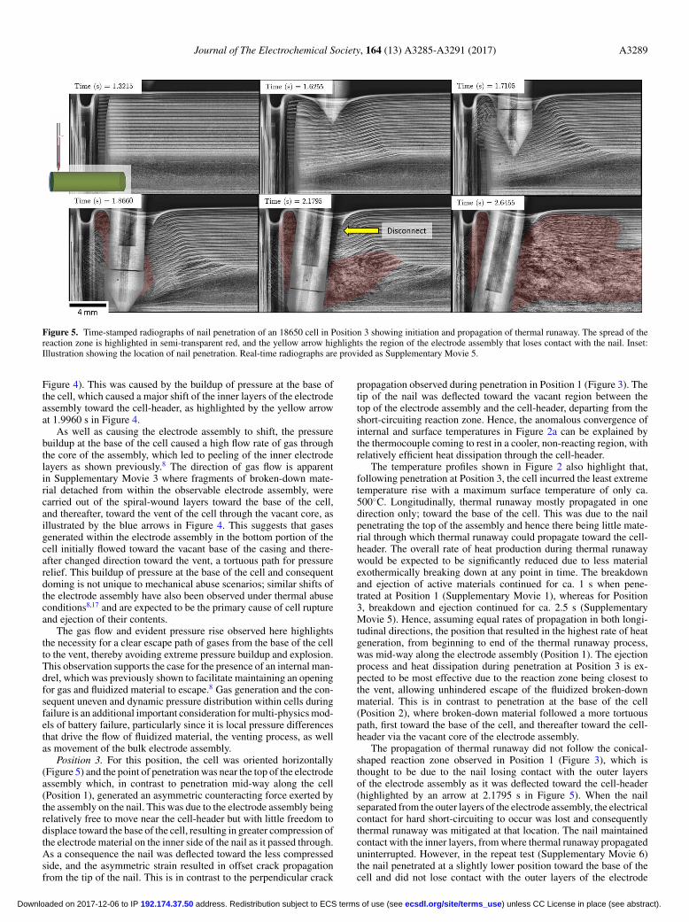
Figure 5. Time-stamped radiographs of nail penetration of an 18650 cell in Position 3 showing initiation and propagation of thermal runaway. The spread of thereaction zone is highlighted in semi-transparent red, and the yellow arrow highlights the region of the electrode assembly that loses contact with the nail. Inset:Illustration showing the location of nail penetration. Real-time radiographs are provided as Supplementary Movie 5.
Figure 4). This was caused by the buildup of pressure at the base ofthe cell, which caused a major shift of the inner layers of the electrodeassembly toward the cell-header, as highlighted by the yellow arrowat 1.9960 s in Figure 4.
As well as causing the electrode assembly to shift, the pressurebuildup at the base of the cell caused a high flow rate of gas throughthe core of the assembly, which led to peeling of the inner electrodelayers as shown previously.8 The direction of gas flow is apparentin Supplementary Movie 3 where fragments of broken-down mate-rial detached from within the observable electrode assembly, werecarried out of the spiral-wound layers toward the base of the cell,and thereafter, toward the vent of the cell through the vacant core, asillustrated by the blue arrows in Figure 4. This suggests that gasesgenerated within the electrode assembly in the bottom portion of thecell initially flowed toward the vacant base of the casing and there-after changed direction toward the vent, a tortuous path for pressurerelief. This buildup of pressure at the base of the cell and consequentdoming is not unique to mechanical abuse scenarios; similar shifts ofthe electrode assembly have also been observed under thermal abuseconditions8,17 and are expected to be the primary cause of cell ruptureand ejection of their contents.
The gas flow and evident pressure rise observed here highlightsthe necessity for a clear escape path of gases from the base of the cellto the vent, thereby avoiding extreme pressure buildup and explosion.This observation supports the case for the presence of an internal man-drel, which was previously shown to facilitate maintaining an openingfor gas and fluidized material to escape.8 Gas generation and the con-sequent uneven and dynamic pressure distribution within cells duringfailure is an additional important consideration for multi-physics mod-els of battery failure, particularly since it is local pressure differencesthat drive the flow of fluidized material, the venting process, as wellas movement of the bulk electrode assembly.
Position 3. For this position, the cell was oriented horizontally(Figure 5) and the point of penetration was near the top of the electrodeassembly which, in contrast to penetration mid-way along the cell(Position 1), generated an asymmetric counteracting force exerted bythe assembly on the nail. This was due to the electrode assembly beingrelatively free to move near the cell-header but with little freedom todisplace toward the base of the cell, resulting in greater compression ofthe electrode material on the inner side of the nail as it passed through.As a consequence the nail was deflected toward the less compressedside, and the asymmetric strain resulted in offset crack propagationfrom the tip of the nail. This is in contrast to the perpendicular crack
propagation observed during penetration in Position 1 (Figure 3). Thetip of the nail was deflected toward the vacant region between thetop of the electrode assembly and the cell-header, departing from theshort-circuiting reaction zone. Hence, the anomalous convergence ofinternal and surface temperatures in Figure 2a can be explained bythe thermocouple coming to rest in a cooler, non-reacting region, withrelatively efficient heat dissipation through the cell-header.
The temperature profiles shown in Figure 2 also highlight that,following penetration at Position 3, the cell incurred the least extremetemperature rise with a maximum surface temperature of only ca.500◦C. Longitudinally, thermal runaway mostly propagated in onedirection only; toward the base of the cell. This was due to the nailpenetrating the top of the assembly and hence there being little mate-rial through which thermal runaway could propagate toward the cell-header. The overall rate of heat production during thermal runawaywould be expected to be significantly reduced due to less materialexothermically breaking down at any point in time. The breakdownand ejection of active materials continued for ca. 1 s when pene-trated at Position 1 (Supplementary Movie 1), whereas for Position3, breakdown and ejection continued for ca. 2.5 s (SupplementaryMovie 5). Hence, assuming equal rates of propagation in both longi-tudinal directions, the position that resulted in the highest rate of heatgeneration, from beginning to end of the thermal runaway process,was mid-way along the electrode assembly (Position 1). The ejectionprocess and heat dissipation during penetration at Position 3 is ex-pected to be most effective due to the reaction zone being closest tothe vent, allowing unhindered escape of the fluidized broken-downmaterial. This is in contrast to penetration at the base of the cell(Position 2), where broken-down material followed a more tortuouspath, first toward the base of the cell, and thereafter toward the cell-header via the vacant core of the electrode assembly.
The propagation of thermal runaway did not follow the conical-shaped reaction zone observed in Position 1 (Figure 3), which isthought to be due to the nail losing contact with the outer layersof the electrode assembly as it was deflected toward the cell-header(highlighted by an arrow at 2.1795 s in Figure 5). When the nailseparated from the outer layers of the electrode assembly, the electricalcontact for hard short-circuiting to occur was lost and consequentlythermal runaway was mitigated at that location. The nail maintainedcontact with the inner layers, from where thermal runaway propagateduninterrupted. However, in the repeat test (Supplementary Movie 6)the nail penetrated at a slightly lower position toward the base of thecell and did not lose contact with the outer layers of the electrode
) unless CC License in place (see abstract). ecsdl.org/site/terms_use address. Redistribution subject to ECS terms of use (see 192.174.37.50Downloaded on 2017-12-06 to IP

A3290 Journal of The Electrochemical Society, 164 (13) A3285-A3291 (2017)
Figure 6. Time-stamped radiographs of nail penetration of an 18650 cell in Position 4 showing initiation and propagation of thermal runaway. The spread of thereaction zone is highlighted in semi-transparent red, and the yellow arrow indicates a major shift of active material toward the vent. Inset: Illustration showing thelocation of nail penetration. Real-time radiographs are provided as Supplementary Movie 7.
assembly, and hence the expected conical-shaped reaction zone wasobserved.
For this particular cell, the electrode layers were able to collapseinto the vacant core. It is expected that the presence of an internalmandrel would significantly affect the mechanism of thermal runawaypropagation; the electrode assembly layers would be pinched betweenthe mandrel and the nail, leading to additional shorting as a result ofcompressive damage.7
Position 4. Here, the 18650 cell was vertically oriented and thenail penetrated through the cell-header (Figure 6). Penetration testswhere the axis of penetration is parallel to the longitudinal directionare expected to result in a relatively hard short circuit due to fewerlayers making contact. Contrary to the expectation that longitudinalpenetration leads to a more severe thermal runaway process, it wasobserved that the rate at which thermal runaway spreads throughoutthe cell appears to be greater when the nail penetrates in the radialdirection (Positions 1 and 3). Since propagation of thermal runawayoccurs at a significantly slower rate in the radial direction than thelongitudinal and azimuthal directions,8,23,24 the rate of propagation ismore dependent on the number of layers in which thermal runawayis initiated along the radial direction. This indicates that, for thisparticular cell, propagation of thermal runaway was limited by therate of propagation radially, rather than the temperature reached in thevicinity of the short.
The temperature at the short-circuiting location was the highestfor this penetration where the cell was placed in the vertical position,reaching 920◦C (Figure 2). The higher temperature did not appearto have significantly accelerated propagation in the radial direction.Despite the temperature being lower across the shorting area whenpenetrated in the vertical direction, a sufficient temperature for thermalrunaway to initiate was still reached across multiple layers in the radialdirection. Thereafter, the greater rate of propagation longitudinally andazimuthally, arising from each layer shorted along the radial direction,resulted in a relatively fast propagation of thermal runaway throughoutthe cell.
Similar to Position 3, the initiation and propagation of thermalrunaway next to the vent allowed a relatively rapid escape of broken-down fluidized material, and hence improved heat dissipation into theenvironment (Figure 6). This is in contrast to the buildup of pressureand displacement of the intact electrode assembly when penetrated
through the base of the cell (Position 2). Avoiding the shift of theintact electrode assembly in this case would have helped avoid therisk of the vent becoming clogged by the intact assembly and sub-sequent rupture of the cell.8 From Supplementary Movie 7, the cellstill showed evidence of reactions occurring 2 s after thermal runawayfirst initiated, indicating a slower rate of completion of the thermalrunaway process compared to penetration at Position 1.
Nail penetration tests: a discussion on variability andrepresentativeness.—This work demonstrates the degree of variabil-ity that can occur during nail penetration tests and highlights thatconsistent reproducible behavior can be difficult to achieve. The widearea over which the short circuit spreads during nail penetration tests,as well as the nail itself acting as a local heat sink, counteracts theextreme temperatures that would otherwise be reached during internalshort circuits, where a much smaller area between a single positive andnegative electrode layer makes unintentional contact. By reducing thelocal temperature, the cell becomes less likely to undergo side-wallrupture, which is one of the greatest safety concerns for battery packmanufacturers due to the increased risk of cell-to-cell propagation ofthermal runaway. The penetrating nail also creates an alternative es-cape path through which generated gases can flow, interfering with thepressure drop toward the vent, and potentially reducing the pressurebuildup that the vent would otherwise experience.
The nail penetration test inherently imposes mechanical interfer-ence on the failure mechanism of the cell, compared to that induced bya local short circuit. This work has shown how the location at whichthe nail penetrates, as well as the orientation of the cell, can influencethe mechanism of failure. When the cell is penetrated while placed inthe horizontal position (Positions 1 and 3) the nail pins the electrodeassembly and obstructs the ejection of cell contents by providing anobstruction perpendicular to the direction of flow. This prevents thesafety devices at the cell header from handling what is otherwise ex-pected to be a more severe ejection process. By resisting movementof the electrode assembly toward the vent of the cell, the nail penetra-tion test could lead to erroneous characterization of the tendency of aparticular cell design to undergo vent-clogging, bursting, and genera-tion of projectiles. The position at which the cell is penetrated whileplaced horizontally also influences the rate of thermal runaway prop-agation; penetration at either end of the electrode assembly induces
) unless CC License in place (see abstract). ecsdl.org/site/terms_use address. Redistribution subject to ECS terms of use (see 192.174.37.50Downloaded on 2017-12-06 to IP

Journal of The Electrochemical Society, 164 (13) A3285-A3291 (2017) A3291
thermal runaway predominantly in the direction toward the oppositeend of the cell, whereas penetration mid-way along the assembly al-lows more prolonged propagation in both directions. When the cell ispenetrated while placed in the vertical position (Positions 2 and 4),the nail is parallel to the electrode assembly and to the direction offlow. In the vertical position, the electrode assembly is not pinned andcan shift toward the vent more freely (as seen in Position 2). However,in the vertical position, the nail may introduce greater shear force andcompression of the electrode assembly against the wall of the cell.Penetrating through the base of the cell presents greater scope fortesting the efficacy of safety devices in the header of the cell, as wellas testing the tendency for vent clogging and cell rupture.
This work clearly demonstrates the variability associated with thenail penetration test and its sensitivity to penetration location and cellorientation. Internal cylindrical mandrels8,17 occupying the core of theelectrode assembly may further affect this variation by introducing thepossibility of the electrode assembly being pinched between the nailand the rigid mandrel. At present, nail penetration tests are frequentlyused to assess the safety of commercial cells and module designs withregard to thermal runaway. As shown here, the combination of thenail softening the short circuit, introducing a heat sink to the regionof initiation, limiting the movement of material within the cell, andrelieving pressure buildup makes nail penetration an ineffective meansof simulation of worst-case failure scenarios. Due to the variation infailure mechanisms and the reduced severity of failure, utilising nailpenetration for the purpose of safety tests raises the possibility oferroneous determination of cell or module safety, since vulnerabilitiesto extreme circumstances such as side-wall rupture or bursting maystill exist.
Conclusions
Internal temperatures were found to be highest for nail penetra-tions where the cell was penetrated while placed in a vertical position.However, despite the higher temperatures being reached locally atthe shorting region, the rate of propagation throughout the cell wasrelatively slow when compared to cells penetrated while placed hori-zontally. The propagation of thermal runaway throughout the cell ap-peared to be limited by the slow heat dissipation and spread of thermalrunaway reactions in the radial direction, rather than the temperaturereached at the point of initiation. The fact that higher temperatureswere reached locally during vertical (longitudinal) penetrations mayhave implications for the risk of thermal runaway at lower states ofcharge, where initiation may be limited by local temperatures – thatis to say, for low state of charge cells, a vertical penetration might bemore likely to result in thermal runaway than a horizontal one.
The high variability of internal structural dynamics that was ob-served between the four penetration positions directly influenced thefailure mechanisms during thermal runaway. Penetration through thebase of the cell and initiation of thermal runaway at the bottom of theelectrode assembly resulted in a local pressure buildup and a rapidflow of material through the vacant core of the assembly. This causedthe bulk electrode assembly to shift toward and clog the vent, which isa known cause of cells bursting. The varying rate of propagation andejection of broken-down material also influenced the external tem-perature profiles that were non-uniform and showed that the hottestregions followed the path of ejection from the point of penetration.
This has implications for temperature measurement strategies on thesurface of the cell where temperatures can vary by >100◦C.
A discussion on the representativeness of nail penetration tests ofin-field failure scenarios highlights the potential for erroneous deter-mination of risks posed by cells undergoing thermal runaway and theneed for a method to induce internal short circuits without an intrusiveobject interfering with the failure mechanism itself. This would allowin-field failures to be more accurately characterized and the efficacyof safety devices against worst-case failure scenarios to be examined.
Acknowledgments
The authors acknowledge funding from the EPSRC(EP/N032888/1, EP/M009394/1), the Royal Academy of Engi-neering, the STFC (ST/N002385/1) and the National MeasurementSystem. These experiments were performed at ID19 at the ESRF(Grenoble, France).
References
1. R. Spotnitz and J. Franklin, Journal of Power Sources, 113, 81 (2003).2. Y. Chen and J. W. Evans, Journal of The Electrochemical Society, 143, 2708 (1996).3. C. -H. Doh, D. -H. Kim, H. -S. Kim, H. -M. Shin, Y. -D. Jeong, S. -I. Moon, B. -S. Jin,
S. W. Eom, H. -S. Kim, K. -W. Kim, D. -H. Oh, and A. Veluchamy, Journal of PowerSources, 175, 881 (2008).
4. A. W. Golubkov, D. Fuchs, J. Wagner, H. Wiltsche, C. Stangl, G. Fauler, G. Voitic,A. Thaler, and V. Hacker, RSC Advances, 4, 3633 (2014).
5. A. W. Golubkov, S. Scheikl, R. Planteu, G. Voitic, H. Wiltsche, C. Stangl, G. Fauler,A. Thaler, and V. Hacker, RSC Advances, 5, 57171 (2015).
6. C. F. Lopez, J. A. Jeevarajan, and P. P. Mukherjee, Journal of The ElectrochemicalSociety, 162, A1905 (2015).
7. J. Lamb and C. J. Orendorff, Journal of Power Sources, 247, 189 (2014).8. D. P. Finegan, E. Darcy, M. Keyser, B. Tjaden, T. M. M. Heenan, R. Jervis,
J. J. Bailey, R. Malik, N. T. Vo, O. V. Magdysyuk, R. Atwood, M. Drakopoulos,M. DiMichiel, A. Rack, G. Hinds, D. J. L. Brett, and P. R. Shearing, Energy & Envi-ronmental Science, 10, 1377 (2017).
9. C. J. Orendorff, E. P. Roth, and G. Nagasubramanian, Journal of Power Sources, 196,6554 (2011).
10. T. Wierzbicki and E. Sahraei, Journal of Power Sources, 241, 467 (2013).11. E. Sahraei, J. Campbell, and T. Wierzbicki, Journal of Power Sources, 220, 360
(2012).12. E. Sahraei, J. Meier, and T. Wierzbicki, Journal of Power Sources, 247, 503 (2014).13. C. Zhang, S. Santhanagopalan, M. A. Sprague, and A. A. Pesaran, Journal of Power
Sources, 298, 309 (2015).14. H. Maleki and J. N. Howard, Journal of Power Sources, 191, 568 (2009).15. K. -C. Chiu, C. -H. Lin, S. -F. Yeh, Y. -H. Lin, and K. -C. Chen, Journal of Power
Sources, 251, 254 (2014).16. W. Zhao, G. Luo, and C. -Y. Wang, Journal of The Electrochemical Society, 162,
A207 (2015).17. D. P. Finegan, M. Scheel, J. B. Robinson, B. Tjaden, I. Hunt, T. J. Mason,
J. Millichamp, M. Di Michiel, G. J. Offer, G. Hinds, D. J. L. Brett, and P. R. Shearing,Nat Communications, 6 (2015).
18. D. P. Finegan, M. Scheel, J. B. Robinson, B. Tjaden, M. Di Michiel, G. Hinds,D. J. L. Brett, and P. R. Shearing, Physical Chemistry Chemical Physics, 18, 30912(2016).
19. T. D. Hatchard, S. Trussler, and J. R. Dahn, Journal of Power Sources, 247, 821(2014).
20. P. Arora and Z. Zhang, Chemical Reviews, 104, 4419 (2004).21. D. P. Finegan, S. J. Cooper, B. Tjaden, O. O. Taiwo, J. Gelb, G. Hinds, D. J. L. Brett,
and P. R. Shearing, Journal of Power Sources, 333, 184 (2016).22. J. Cannarella, X. Liu, C. Z. Leng, P. D. Sinko, G. Y. Gor, and C. B. Arnold, Journal
of The Electrochemical Society, 161, F3117 (2014).23. S. Santhanagopalan, P. Ramadass, and J. Zhang, Journal of Power Sources, 194, 550
(2009).24. G. -H. Kim, A. Pesaran, and R. Spotnitz, Journal of Power Sources, 170, 476 (2007).
) unless CC License in place (see abstract). ecsdl.org/site/terms_use address. Redistribution subject to ECS terms of use (see 192.174.37.50Downloaded on 2017-12-06 to IP