Embed Size (px)
Citation preview

emScon 3.0Programmers ManualTracker Programming Interface

Programmers Manual
emScon TPI
Metrology Division
1
Preface
These are original instructions and part of the product. Keep for future reference and pass on to subsequent holder/user of product. Read instructions before setting‐up and operating the hard‐ and software. This reference manual contains information protected by copyright and subject to change without notice. No part of this reference manual may be reproduced in any form without prior and written consent from Leica Geosystems AG. Leica Geosystems AG shall not be responsible for technical or editorial errors or omissions. Product names are trademarks or registered trademarks of their respective companies. The software described herein is furnished under license and non‐disclosure agreement, and may be used only in accordance with the terms of the sales agreement. © Leica Geosystems AG Feedback Your feedback is important as we strive to improve the quality of our documentation. We request you to make specific comments as to where you envisage scope for improvement. Please use the following E‐Mail address to send in suggestions: documentation.metrology@leica‐geosystems.com Software and version emScon TPI; V3.0 Manual update May 26, 2008
Manual order number None
2

Preface Contact
Leica Geosystems AG Metrology Division Moenchmattweg 5 5035 Unterentfelden Switzerland Phone ++41 +62 737 67 67 Fax ++41 +62 723 07 34 www.leica‐geosystems.com/metrology
3
1 Contents
1 CONTENTS............................................................. 4
2 INTRODUCTION ..................................................... 8
2.1 Prerequisites ...................................................................................... 8 2.1.1 Targeted Users and Terminology............................................. 8 2.1.2 Common Abbreviations ........................................................... 8 2.1.3 Supported Leica Hardware..................................................... 10 2.1.4 Network requirements............................................................ 10 2.1.5 Programming Environment.................................................... 11
2.2 TCP/IP Communication ................................................................. 11 2.2.1 Socket Functions .................................................................... 11
2.3 Tracker Programming Interface ................................................... 13 2.3.1 Platform and Programming Language Issues......................... 14 2.3.2 Prefixes and Suffixes used in Type Names............................ 15 2.3.3 Asynchronous Communication.............................................. 15 2.3.4 Working Conditions............................................................... 16 2.3.5 Coordinate Parameter Triplets ............................................... 18 2.3.6 Persistency ............................................................................. 19 2.3.7 Default Settings...................................................................... 19 2.3.8 Application Backward Compatibility..................................... 20 2.3.9 Sample Code .......................................................................... 23
2.4 Application Initial Steps ................................................................. 25 2.4.1 Essential Steps........................................................................ 25 2.4.2 Command Sequence for 3D Measurements ........................... 27 2.4.3 Command Sequence for 6DoF Measurements....................... 29 2.4.4 Initial Steps Description in Detail .......................................... 31 2.4.5 Automatic External Device Recognition................................ 40
3 C - INTERFACE .................................................... 43
3.1 Low-level TPI Programming.......................................................... 43 3.1.1 Preconditions.......................................................................... 43 3.1.2 Recommendation ................................................................... 43 3.1.3 Byte Alignment ...................................................................... 44 3.1.4 Little/Big Endians .................................................................. 44 3.1.5 Preprocessor Statements ........................................................ 45 3.1.6 TPI 'Boolean' Data Type ........................................................ 45 3.1.7 Enumeration-Type Members Numerical representation ........ 46 3.1.8 Basic C Data Type size of TPI Structures.............................. 46
3.2 Communication Basics.................................................................... 46 3.2.1 Sending Commands ............................................................... 46 3.2.2 Command Answers ................................................................ 47 3.2.3 Error Events ........................................................................... 51 3.2.4 System Status Change Events ................................................ 51 3.2.5 3D / 6 DoF – Related commands ........................................... 52
3.3 C- Language TPI Reference........................................................... 53 3.3.1 Constants................................................................................ 53
4
3.3.2 Enumeration Types ................................................................ 54
3.4 Data Structures ............................................................................. 166 3.4.1 Basic Data Structures ........................................................... 166 3.4.2 Packet Data Structures ......................................................... 184
3.5 C - Language TPI Programming Instructions ........................... 244 3.5.1 TCP/IP Connection .............................................................. 245 3.5.2 Sending Commands ............................................................. 245 3.5.3 Initialization Macros ............................................................ 246 3.5.4 Excurse: C++ Initialization .................................................. 246 3.5.5 Answers from Tracker Server .............................................. 247 3.5.6 Asynchronous Communication............................................ 247 3.5.7 DataArrived Notification ..................................................... 247 3.5.8 Data arrival 'Traffic Jams' .................................................... 248 3.5.9 PacketHeader Masking ........................................................ 249 3.5.10 Command Subtype Switch................................................... 249
3.6 C Language TPI - Samples........................................................... 251 3.6.1 Sample 3............................................................................... 251
4 C++ INTERFACE ................................................ 255
4.1 Class- based TPI Programming................................................... 255 4.1.1 Preconditions........................................................................ 255 4.1.2 Platform Issues..................................................................... 256 4.1.3 TCP/IP.................................................................................. 256
4.2 C++ Language TPI Reference...................................................... 256 4.2.1 CESAPICommand class....................................................... 256 4.2.2 CESAPIReceive class .......................................................... 258
4.3 C++ Language TPI Programming Instructions ......................... 260 4.3.1 Sending Data........................................................................ 260 4.3.2 Receiving Data..................................................................... 261 4.3.3 Class Design Issues.............................................................. 261 4.3.4 Data Structure Wrapper Classes .......................................... 262 4.3.5 CESAPICommand ............................................................... 263 4.3.6 CESAPIReceive ................................................................... 265 4.3.7 Queued and Scattered Data .................................................. 266 4.3.8 Partial Settings Changes....................................................... 271 4.3.9 Asynchronous Programming Issues..................................... 272 4.3.10 Working with multiple trackers ........................................... 276
4.4 C++ Language TPI Samples......................................................... 279 4.4.1 Sample 4............................................................................... 279 4.4.2 Sample 9............................................................................... 283 4.4.3 Sample 12............................................................................. 283 4.4.4 Sample 19............................................................................. 285
5 COM - INTERFACE............................................. 286
5.1 High-level TPI Programming....................................................... 286 5.1.1 Drawbacks............................................................................ 286 5.1.2 Introduction.......................................................................... 286
5.2 COM TPI Programming Instructions......................................... 288 5.2.1 VisualBasic and VBA Applications..................................... 288 5.2.2 C++ Applications ................................................................. 292 5.2.3 Notification Method............................................................. 293 5.2.4 Exceptions and Return Types .............................................. 295 5.2.5 COM TPI supporting Programming Languages .................. 298 5.2.6 Proper Interface Selection.................................................... 300 5.2.7 Type- Library ....................................................................... 302 5.2.8 COM TPI Reference ............................................................ 303
5
5.2.9 Registering COM Objects .................................................... 304 5.2.10 Synchronous versus Asynchronous Interface ...................... 304 5.2.11 Visual Basic Boolean variable evaluation............................ 305 5.2.12 Reading Data Blocks with Visual Basic .............................. 306 5.2.13 VBA Macro-Language Support ........................................... 307 5.2.14 Continuous measurements and VBA ................................... 310 5.2.15 Scripting Language Support................................................. 313 5.2.16 Exception Handling for Non- Microsoft Clients.................. 313 5.2.17 Multi- Tracker Applications................................................. 314
5.3 COM TPI Samples ........................................................................ 326 5.3.1 Sample 5............................................................................... 326 5.3.2 Sample 7............................................................................... 335 5.3.3 Sample 8............................................................................... 342 5.3.4 Sample 14............................................................................. 342 5.3.5 Sample 15............................................................................. 343 5.3.6 Sample 18............................................................................. 343 5.3.7 Sample 20............................................................................. 343
6 C# - INTERFACE ................................................ 345
6.1 Client Programming with C#....................................................... 345 6.1.1 Introduction.......................................................................... 345 6.1.2 C# Application Programming .............................................. 345 6.1.3 Sample 16............................................................................. 346 6.1.4 Sample 17............................................................................. 347 6.1.5 Multi- Tracker C# Applications ........................................... 349
7 BASE USER INTERFACE (BUI)......................... 354
7.1 Client Programming and BUI...................................................... 354 7.1.1 Measurement BUI versus Compensation Applications........ 354 7.1.2 EmScon Basic User Interface (BUI) .................................... 355 7.1.3 Integration of BUI into applications .................................... 355 7.1.4 Sample 13............................................................................. 356
8 SELECTED COMMANDS IN DETAIL................. 357
8.1 Special Functions........................................................................... 357 8.1.1 Get Reflectors Command..................................................... 357 8.1.2 Still Image Command .......................................................... 361 8.1.3 Live Image display............................................................... 367 8.1.4 Orient To Gravity Procedure................................................ 374 8.1.5 Transformation Procedure.................................................... 375 8.1.6 Automated Intermediate Compensation............................... 378 8.1.7 Two Face Field-Check ......................................................... 382
9 MATHEMATICS .................................................. 387
9.1 Point accuracy ............................................................................... 387 9.1.1 A priori accuracy.................................................................. 387 9.1.2 A posteriori accuracy ........................................................... 388 9.1.3 Transformation of covariance matrices................................ 388
9.2 Orientation and Transformation ................................................. 389 9.2.1 Orientation ........................................................................... 389 9.2.2 Transformation..................................................................... 390 9.2.3 Nominal and actual coordinates ........................................... 391 9.2.4 Orientation parameters ......................................................... 391 9.2.5 Transformation parameters .................................................. 392 9.2.6 Input to transformation computation.................................... 392 9.2.7 Output of transformation computation................................. 394 9.2.8 Examples.............................................................................. 396
6

9.3 T-Probe .......................................................................................... 398
10 APPENDICES ..................................................... 400
10.1 Tracker Trigger Interface [A] ................................................ 400
10.2 Server Error Numbers [B]...................................................... 400
10.3 Tracker / TP Error Numbers [C]........................................... 400
10.4 T-Cam / T-Probe Error Numbers [D] ................................... 400
10.5 AIFM Error Numbers [E] ...................................................... 401
7
2 Introduction
2.1 Prerequisites 2.1.1 Targeted Users and Terminology This manual applies to software developers who need to write software that directly communicates with Leica‐ Tracker hardware (or Tracker servers ‐ aka emScon servers, respectively). This manual hence describes the Application Programmers Interface (API) for Leica Trackers / Tracker Servers (emScon). API is a widely used term in the programming world. In order to clearly distinguish from other APIs (Win32 API, Winsocket API…) referenced in this manual, we are rather using the term Tracker Programming Interface (TPI). TPI therefore stands as a synonym for Leica Tracker API throughout this manual. Note that this is not a User‐ Manual for trackers! Users of this Reference Manual need to be familiar with tracker operation concepts and tracker‐specific terms such as ʹBird bathʹ, ʹAbsolute Distance Meterʹ etc. These terms are usually not explained here. The Programmers Manual just means an extension to the provided User‐, Reference‐ and Training‐ Manuals for Leica Trackers and emScon. 2.1.2 Common Abbreviations IT / Windows / Microsoft specific API Application
Programmers Interface ATL Active Template Library
8
COM Component Object Library
DLL Dynamic Link Library GUI Graphical User Interface IDE Integrated Development
Environment IDL Interface Description
Language LAN Local Area Network LED Light Emitting Diode OCX ActiveX Control NYI Not yet implemented TCP/IP Transmission Control
Protocol / Internet Protocol
UI User Interface VB Visual Basic
Visual Basic for Applications (a subset of VB, Macro Language)
VBA
VC++ Visual C++ VS Visual Studio (= IDE)
Leica / emScon specific ADM Absolute Distance Meter BB BirdBath (sometimes also
BallBar) BUI Base User Interface CS Coordinate System DoF Degrees of Freedom
(mainly used as 6DoF) ES Embedded System (=
server‐based system) FW Firmware HV Horizontal / Vertical
(2DoF angular measurement pair)
9
HVD Horizontal / Vertical / Distance (3DoF measurement triplet)
IFM Interferometer LT Laser Tracker (w/o ADM)LTD / AT Laser Tracker with ADM NYI Not yet implemented TPI Tracker Programming
Interface (= API) TS Tracker Server TP Tracker Processor Trafo Transformation T‐Cam / TCam Tracker Camera T‐Probe Tracker Probe T‐Mac Tracker Machine Control
Probe V‐Cam Video Camera (overview
camera) WM Weather Monitor
2.1.3 Supported Leica Hardware The emScon TPI supports the following Laser Trackers and T‐Products:
• LT500 & LTD500
• LT600 & LTD600 Series
• LTD700 Series
• LT800 & LTD800 Series
• T‐Cam 700 and 800 Series
• AT Tracker Series (AT901‐B/MR/LR)
• T‐Cam LR and MR Series
2.1.4 Network requirements Communication between user‐ applications and emScon tracker server is based on the TCP/IP
10
protocol. The application PC thus must be equipped with a TCP/IP‐enabled LAN Board.
• This manual does not cover hardware and network installation/configuration issues.
2.1.5 Programming Environment This manual (notation, samples) is mainly based on Microsoft Visual Studio 6.0 (VC++ 6.0, Visual Basic 6.0). Some samples refer to VisualStudio 7.0 (C# and VB .NET samples). Compatibility to Microsoft Visual Studio 7.0 (8.0) is granted for all C/C++/COM interfaces/Samples. The samples written in VB 6.0 require a conversion and possibly some minor code‐ adjustments in order to compile under VB.NET.
2.2 TCP/IP Communication Communication through TCP/IP requires platform specific communication functions. These are not part of the emScon TPI; they are provided by the Operating System or by the IDE. There exist several so‐called Socket APIs. Keywords under Windows/VC++ include Win32 Sockets API, or (if using MFC) CAsyncSocket and CSocket. Visual Studio even contains a TCP/IP communication library, MSWinsck.ocx, as an ActiveX control (COM object). Any of these socket interfaces may be used in order to communicate with emScon. 2.2.1 Socket Functions For writing emScon applications, only few socket‐ functions are required (names may be different, depending on used Library/API):
• Connect – Establishes a TCP/IP connection from the application to the Tracker Server. IP‐ address/hostname and port number of
11
the Tracker Server are required as parameters.
• SendData – Send a packet of data to the server, usually by passing a pointer to a byte array data‐block and the size of that block.
• ReceiveData – Callback‐ or Event‐ Notification. A mechanism to notify the application when data has arrived from the server and is ready to be read.
• ReadData – To read waiting data into a byte‐array buffer, upon a notification.
• Close – Closes a previously established TCP/IP connection.
Availability of socket functions: There are several options. The decision, which one to use, may depend on several facts: the platform, the programming language, the type of the application (Console Application, Windows Application with GUI, Server Application running in background...) etc.
• Operating system provided low‐level socket API (e.g. Winsock 2.0 API of Windows). This approach requires some advanced programming knowledge.
• Class libraries, for example MFC, provide a higher‐level abstraction of the Winsock functions. Easier to use.
• ActiveX Controls / COM libraries. For example MSWINSCK.OCX. Suitable especially for VB/VBA applications.
• Third party TCP/IP communication library or component.
• Self developed TCP/IP library (based on low‐level Win32 API).
12
2.3 Tracker Programming Interface EmScon provides a TCP/IP interface. Communicating with the emScon server hence means sending and receiving byte‐array data‐blocks over an (asynchronous) network connection. This technique has no specific relation to emScon ‐ itʹs how any TCP/IP communication works ‐ including Internet browsing. EmScon specific issues are brought into by just publishing the structure of the sent/received data packets. The emScon TPI (low‐level interface) is therefore a collection of Data Types, namely Enumeration Types and Data Structures. Thatʹs all! These data types fully describe the structure of the data blocks traveling over the TCP/IP network. They are required to ʹconstructʹ blocks to be sent to the tracker‐server and can be used to ʹmaskʹ incoming data blocks in order to interpret these. The definition of these data‐types is provided in C‐language notation, as an include‐file called ES_C_API_Def.h. This file is compatible to the IDL‐language, and its types are therefore fully transparent to COM interfaces (except constants). (Note the subtle differences between C and C++ notation for structs and enums)
The ES_C_API_Def.h file is the only interface definition of the emScon TPI, also referred to as the ʹnativeʹ emScon interface. All other interface levels (C++ TPI, C# TPI, LT‐Control COM ‐ interface) are higher level abstractions and are strictly based on this native include‐file. They are, therefore, just provided for convenience. This enables the client programmer to design alternate C++/C# interfaces and/or other high‐level interfaces (e.g. even COM components). However, the ES_C_API_Def.h file should not
13
be changed on any account. 2.3.1 Platform and Programming Language Issues • The versatility of the emScon TPI based on
standard TCP/IP allows its usage on different operating systems (Windows, Linux, UNIX, Macintosh…).
• Despite the C‐language native interface, the programming language for writing emScon applications is not restricted to C. All languages that can deal with structures in C‐notation (or have the same byte‐align policy), can be used. The use of languages other than C/C++ may, however, require translation of C‐structures (ES_C_API_Def.h) to the target languageʹs notation, with matching structures on the byte level (4 Byte alignment). Such translations require some advanced programming knowledge and are not covered by this Manual.
• The use of programming languages other than C/C++ is not recommended for low‐ level TPI programming, and no support is provided. Translating the TPIʹs Enumeration Types and Data Structures into other languageʹs syntax may encounter potential errors (different size of basic data types, byte alignment issues etc.).
• Applications therefore should not be based directly on the C‐ native interface. Usage of provided C++, C# or COM emScon interfaces is highly recommended instead.
14
2.3.2 Prefixes and Suffixes used in Type Names Prefixes
ES ʹEmbedded Systemʹ (or emScon). They identify type‐names of the TPI
DT Data type (Packet type) C Command RS Result Status SSC System Status Change
(Events)
Suffixes
T Type; usually used for general sub‐structures
RT Return Type (used for data transfer from server)
CT Command Type (used for data transfer to server)
These are only the most frequent ones. Other prefixes explain themselves as they mostly are derived from the enum‐type‐ names. 2.3.3 Asynchronous Communication As for any TCP/IP communication, low‐level communication (C/C++) to the tracker server is asynchronous. In particular, this means:
• A SendData function will always return immediately without waiting for an answer. Depending on the command, several seconds may expire before the answer arrives (through a notification or callback).
• Each TPI command causes an (asynchronous) answer (sort of an acknowledgment). Hence, commands and answers usually occur ʹpair‐ wiseʹ. Some commands, however, will result in more
15
than one result packet. There is no command at all that does not respond with an answer of some sort!
• Some Error Event types (for example ʹbeam brokenʹ) can occur at any time and are not direct reactions to a command (So called unsolicited events). An application should be prepared to ʹcatchʹ these at any time.
• There are numerous ʹSystem Change Eventsʹ that can occur at any time. An application may evaluate these (mainly for GUI update);
• The tracker server high‐level interface (COM) provides both asynchronous and, to a certain degree, synchronous communication. However, some answer types are always asynchronous by their nature, even when using the synchronous interface.
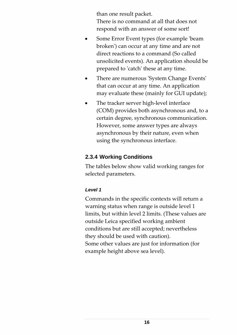
2.3.4 Working Conditions The tables below show valid working ranges for selected parameters. Level 1
Commands in the specific contexts will return a warning status when range is outside level 1 limits, but within level 2 limits. (These values are outside Leica specified working ambient conditions but are still accepted; nevertheless they should be used with caution). Some other values are just for information (for example height above sea level).
16
Working ambient conditions
Minimum value Maximum value
Temperature + 5°C + 40°C Height above sea level/elevation (not relevant for software) ‐500 m +3000 m Air pressure 600 mbar 1170 mbar Relative humidity 10% 90% Refraction index IFM 1.00015 1.000331 Refraction index ADM 1.000152 1.000336
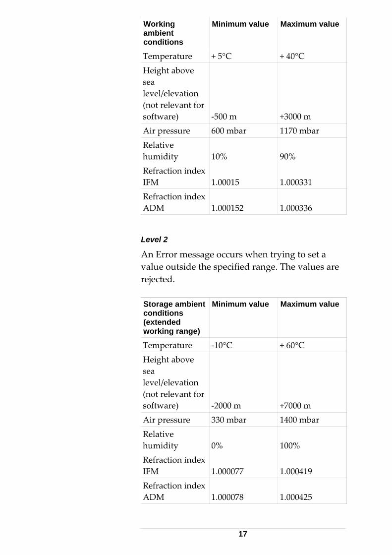
Level 2
An Error message occurs when trying to set a value outside the specified range. The values are rejected. Storage ambient conditions (extended working range)
Minimum value Maximum value
Temperature ‐10°C + 60°C Height above sea level/elevation (not relevant for software) ‐2000 m +7000 m Air pressure 330 mbar 1400 mbar Relative humidity 0% 100% Refraction index IFM 1.000077 1.000419 Refraction index ADM 1.000078 1.000425
17
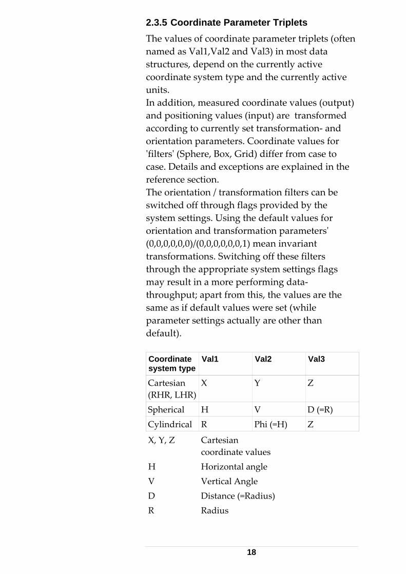
2.3.5 Coordinate Parameter Triplets The values of coordinate parameter triplets (often named as Val1,Val2 and Val3) in most data structures, depend on the currently active coordinate system type and the currently active units. In addition, measured coordinate values (output) and positioning values (input) are transformed according to currently set transformation‐ and orientation parameters. Coordinate values for ʹfiltersʹ (Sphere, Box, Grid) differ from case to case. Details and exceptions are explained in the reference section. The orientation / transformation filters can be switched off through flags provided by the system settings. Using the default values for orientation and transformation parametersʹ (0,0,0,0,0,0)/(0,0,0,0,0,0,1) mean invariant transformations. Switching off these filters through the appropriate system settings flags may result in a more performing data‐throughput; apart from this, the values are the same as if default values were set (while parameter settings actually are other than default). Coordinate system type
Val1 Val2 Val3
Cartesian (RHR, LHR)
X Y Z
Spherical H V D (=R) Cylindrical R Phi (=H) Z
X, Y, Z Cartesian coordinate values
H Horizontal angle V Vertical Angle D Distance (=Radius)R Radius
18
PHI Horizontal Angle (=H)
Different notations of values in different systems (Phi instead of H, D instead of R) maintain continuity with previous releases of application software. 2.3.6 Persistency The tracker server keeps most settings (such as Units, CS‐type, Reflector type etc.) persistently. Recent values will be restored on restart of the Tracker‐ server.
It is recommended to initially set the required settings, on every client startup – as good programming practice. An application should never rely on certain settings already be done ‐ another application/user may have changed these in the meantime! Some (mainly critical) settings are intentionally set back to default values upon server reset. 2.3.7 Default Settings List of the most common parameters and their default factory‐ settings:
• Orientation parameters: {0,0,0,0,0,0}
• Transformation parameters: {0,0,0,0,0,0,1} (scale factor is 1)
• CS‐Type: RHR (right handed rectangular)
• Length: Meter
• Angle: Radian
• Temperature: Celsius
• Pressure: Hecto‐pascal = Millibar
• Rel. Humidity: 70%
• Temperature: 20.0°C
• Pressure: 1013.25 mbar (760 mmHg)
19
• Measurement mode: Stationary
• Temperature range: Medium
• Reflector: None
• Interferometer refr. index: 1.0002711152
• ADM refraction index: 1.0002748652
• Stationary point measurement time:2500 ms
• Continuous measurement; time: 500 ms
• Continuous measurement; number of points: 0 (means infinite)
• Statistic mode: Standard
• Region and grid mode parameters: Arbitrary.
Other, less‐ common settings, are described in the command reference section. 2.3.8 Application Backward Compatibility New data types/packets with evolving server versions This is a very important issue in order to prevent existing application software will break when used in combination with future emScon server software upgrades. Future versions of emScon may provide new/extended data over the TCP/IP connection, such as new packet types (new commands), new status messages and new error messages. Backward compatibility will be provided, in that existing packets/information structure are neither changed nor removed from the TPI definition (except when explicitly announced), but new one may be added/appended with new server versions. However, applications must be designed in a way so they ignore any unknown or unexpected data. In practice, this generally means that default cases in switch statements should always be
20
treated as ʹneutralʹ (no action).
Example:
The enum ʹES_SystemStatusChangeʹ in emScon V1.2 contained only two members: enum ES_SystemStatusChange { ES_SSC_DistanceSet, ES_SSC_LaserWarmedUp, };
EmScon V1.2 had only two system status change events, as shown above. With emScon version 1.4 (and higher), many more status change events have been introduced (See C‐ API def file).
A programming statement in a client application (originally developed under V1.2) as shown below, would cause an ʹUnexpected Statusʹ message with V1.4 (and higher) emScon servers upon any of the new status events; the application thus would probably fail in combination with a V1.4 emScon server and would require code‐ adjustments. switch (status) { case ES_SSC_DistanceSet: AfxMessageBox(“ADM Distance re-established”); break; case ES_SSC_LaserWarmedUp: AfxMessageBox(“Laser is now ready”); break; default: AfxMessageBox(“Unexpected Status”); break; // WRONG!!! };
Solution:
Ignore the default case by doing no action at all (or one that just has an effect to debug versions). default: // No action at all break; or default: // no effect to retail versions TRACE(“Unexpected Status”); ASSERT(false); break;
Summary: emScon client application only must interpret KNOWN, i.e. defined data according to enums/structs in current C‐ API file. All other data must be ignored.
21
Only if this rule is attended, existing emScon client applications will also run with future emScon server upgrades. Otherwise, application source may need to be adjusted to be compliant to new server versions. Applications supporting different server versions
If an application is required to support tracker hardware with different capability and/or several emScon server versions, some important version checking issues apply. Consider for example that the same application should be able to deal with emScon V1.5 (3D only) as well as with emScon V2.0 and up (3D trackers as well 6DoF systems). Since newer emScon server versions always are backward compatible ‐ that is, all previous commands are also covered by the newer versions ‐ there is usually no problem to run an already existing application on a newer server version (exceptions see previous chapter). The problem starts for applications that should support 6DoF systems (emScon server V2.0 and up), but should also be able to deal with 3D trackers running on an emScon V1.5 server. In order to run properly, such an application should check the server version upon startup and make provisions to prevent calls not suitable to a particular server version. The version info can be queried from the server; it is part of the information delivered by the ʹGetSystemStatusʹ command (ESVersionNumber). Depending on this version, the application has to allow/prevent commands for execution. If the queried server version for example evaluates to 1.5, the application would have to block (for example gray‐out menus) all 6DoF related commands. See ʹenum ES_Commandʹ in file ES_C_Api_def.h for availability of commands in what version.
22
There are comments such as // New commands added for release 2.0
2.3.9 Sample Code The samples/tutorials, which are part of the SDK and which have to be regarded as integral part of this manual, show the principles of TPI programming in terms of ready to compile/use applications. However, most sample applications may not be of real practical use, with respect to the specific TPI commands they implement. The focus of the samples is set to show principles of tracker control. Initial Steps In a practical application, in order to get accurate results, it is crucial to implement all the steps as listed under ʹInitial stepsʹ. Minimal Code The number of files and code‐ overhead in the samples has been kept to a minimum. Code generated from wizards, such as recompiled headers, icon, res2 includes and ʹcosmetic functionsʹ, have been stripped off. See also the numerous comments in the sample source files and the ʹReadMe.txtʹ files in each sample folder. Error Handling
The samples do not always implement complete error handling and may need to be run through the debugger in order to find failure reasons. Interface Design
The user interface design is kept at a minimum level (for example, unavailable buttons are not grayed out). Such items are general issues of
23

Windows programming. Hard Coded Information
The samples may contain some hard‐coded information (IP address/coordinate values) that might be adapted to the local environment.
24

2.4 Application Initial Steps 2.4.1 Essential Steps A client application must carry out all steps listed below upon startup. Omitting some of these steps may prevent the tracker from measuring or lead to inaccurate results. Inaccurate results are difficult to detect. Setting correct environment parameters (temperature, pressure, humidity) or configuring the system for automatic, environment parameter reading is crucial. Most of the Settings (ʹSetʹ‐ commands) remain persistent. That is, they will be the same after a system restart. However, it is strongly recommended that an application always confirms these settings upon startup. This is because another application (e.g. emScon Base User Interface) could have accessed the tracker server in the meantime and could have changed the settings. Note that most of the sample applications are not complete to this respect – the intention of the Samples is to show programming principles only. See also Leica Tracker/Training Manual. Important: The emScon Compensation Application (Web Application) sets the system into a special mode called Compensation Mode. If this mode is active, all commands will return with an error status ʹES_RS_InCompensationModeʹ. In other words: The TPI interface is locked while a Compensation / Field check is being performed. A client application, upon startup, should therefore verify the system is not in compensation mode. This can be done explicitly by using any
25
ʹGet...ʹ command: If the command completes with ʹES_RS_AllOKʹ, the system is NOT in compensation mode. If the status ʹES_RS_InCompensationModeʹ is returned, the application should inform the user and exit. Checking the compensation mode can also be done ʹimplicitlyʹ by evaluating the status of the very first command the application sends after connecting to the server. This can be any ʹSet...ʹ or a ʹGet...ʹ command.
26
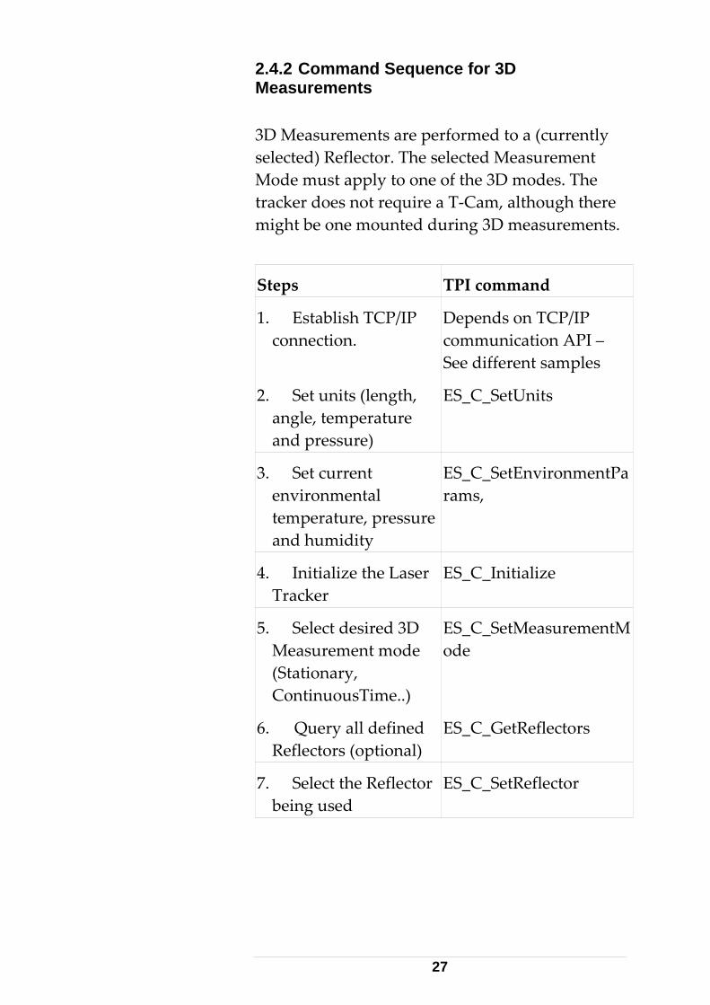
2.4.2 Command Sequence for 3D Measurements 3D Measurements are performed to a (currently selected) Reflector. The selected Measurement Mode must apply to one of the 3D modes. The tracker does not require a T‐Cam, although there might be one mounted during 3D measurements.
Steps TPI command
1. Establish TCP/IP connection.
Depends on TCP/IP communication API – See different samples
ES_C_SetUnits 2. Set units (length, angle, temperature and pressure)
ES_C_SetEnvironmentParams,
3. Set current environmental temperature, pressure and humidity
4. Initialize the Laser Tracker
ES_C_Initialize
5. Select desired 3D Measurement mode (Stationary, ContinuousTime..)
ES_C_SetMeasurementMode
6. Query all defined Reflectors (optional)
ES_C_GetReflectors
7. Select the Reflector being used
ES_C_SetReflector
27
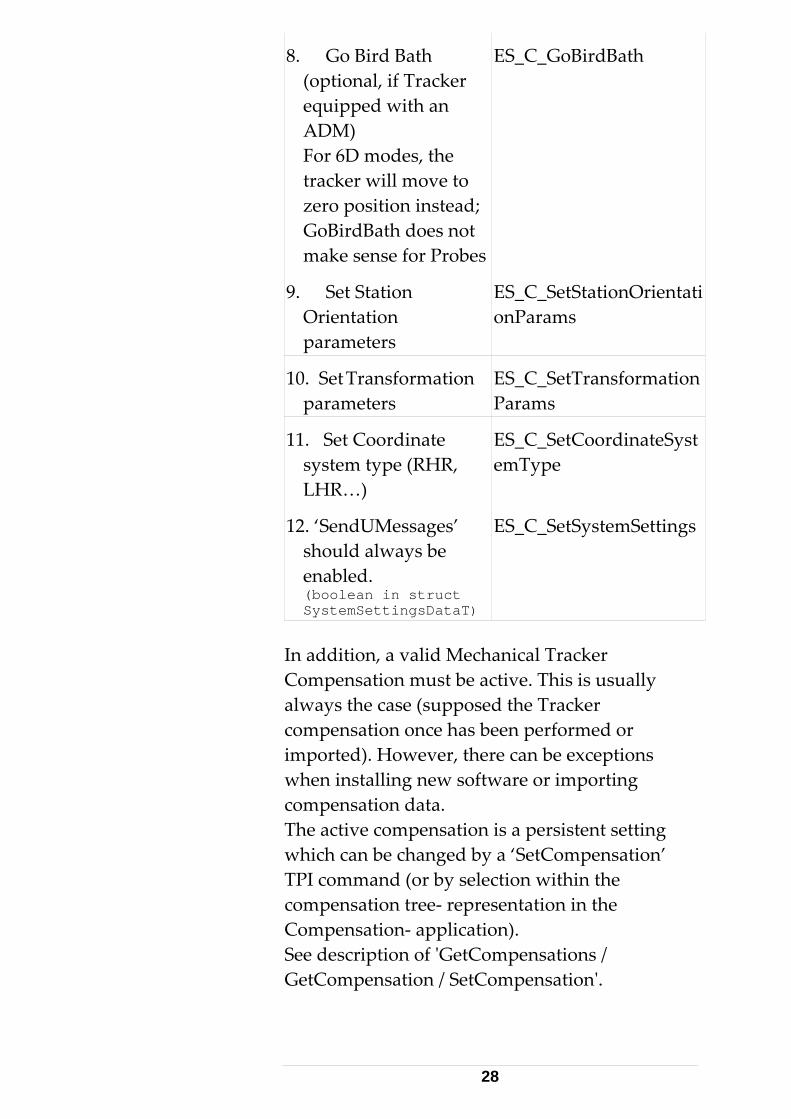
ES_C_GoBirdBath 8. Go Bird Bath (optional, if Tracker equipped with an ADM) For 6D modes, the tracker will move to zero position instead; GoBirdBath does not make sense for Probes
ES_C_SetStationOrientationParams
9. Set Station Orientation parameters
10. Set Transformation parameters
ES_C_SetTransformationParams
ES_C_SetCoordinateSystemType
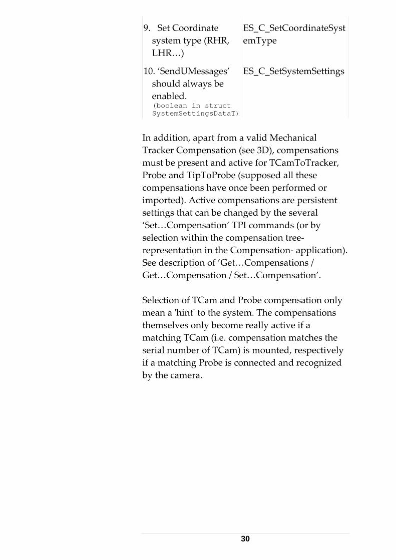
11. Set Coordinate system type (RHR, LHR…)
12. ‘SendUMessages’ should always be enabled. (boolean in struct SystemSettingsDataT)
ES_C_SetSystemSettings
In addition, a valid Mechanical Tracker Compensation must be active. This is usually always the case (supposed the Tracker compensation once has been performed or imported). However, there can be exceptions when installing new software or importing compensation data. The active compensation is a persistent setting which can be changed by a ‘SetCompensation’ TPI command (or by selection within the compensation tree‐ representation in the Compensation‐ application). See description of ʹGetCompensations / GetCompensation / SetCompensationʹ.
28
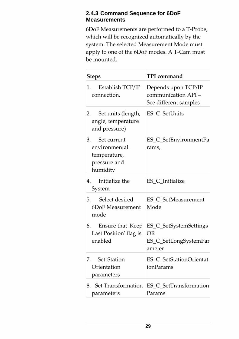
2.4.3 Command Sequence for 6DoF Measurements 6DoF Measurements are performed to a T‐Probe, which will be recognized automatically by the system. The selected Measurement Mode must apply to one of the 6DoF modes. A T‐Cam must be mounted.
Steps TPI command
1. Establish TCP/IP connection.
Depends upon TCP/IP communication API – See different samples
ES_C_SetUnits 2. Set units (length, angle, temperature and pressure)
ES_C_SetEnvironmentParams,
3. Set current environmental temperature, pressure and humidity
4. Initialize the System
ES_C_Initialize
ES_C_SetMeasurementMode
5. Select desired 6DoF Measurement mode
ES_C_SetSystemSettings OR ES_C_SetLongSystemParameter
6. Ensure that ʹKeep Last Positionʹ flag is enabled
ES_C_SetStationOrientationParams
7. Set Station Orientation parameters
8. Set Transformation parameters
ES_C_SetTransformationParams
29
ES_C_SetCoordinateSystemType
9. Set Coordinate system type (RHR, LHR…)
10. ‘SendUMessages’ should always be enabled. (boolean in struct SystemSettingsDataT)
ES_C_SetSystemSettings
In addition, apart from a valid Mechanical Tracker Compensation (see 3D), compensations must be present and active for TCamToTracker, Probe and TipToProbe (supposed all these compensations have once been performed or imported). Active compensations are persistent settings that can be changed by the several ‘Set…Compensation’ TPI commands (or by selection within the compensation tree‐ representation in the Compensation‐ application). See description of ‘Get…Compensations / Get…Compensation / Set…Compensation’. Selection of TCam and Probe compensation only mean a ʹhintʹ to the system. The compensations themselves only become really active if a matching TCam (i.e. compensation matches the serial number of TCam) is mounted, respectively if a matching Probe is connected and recognized by the camera.
30
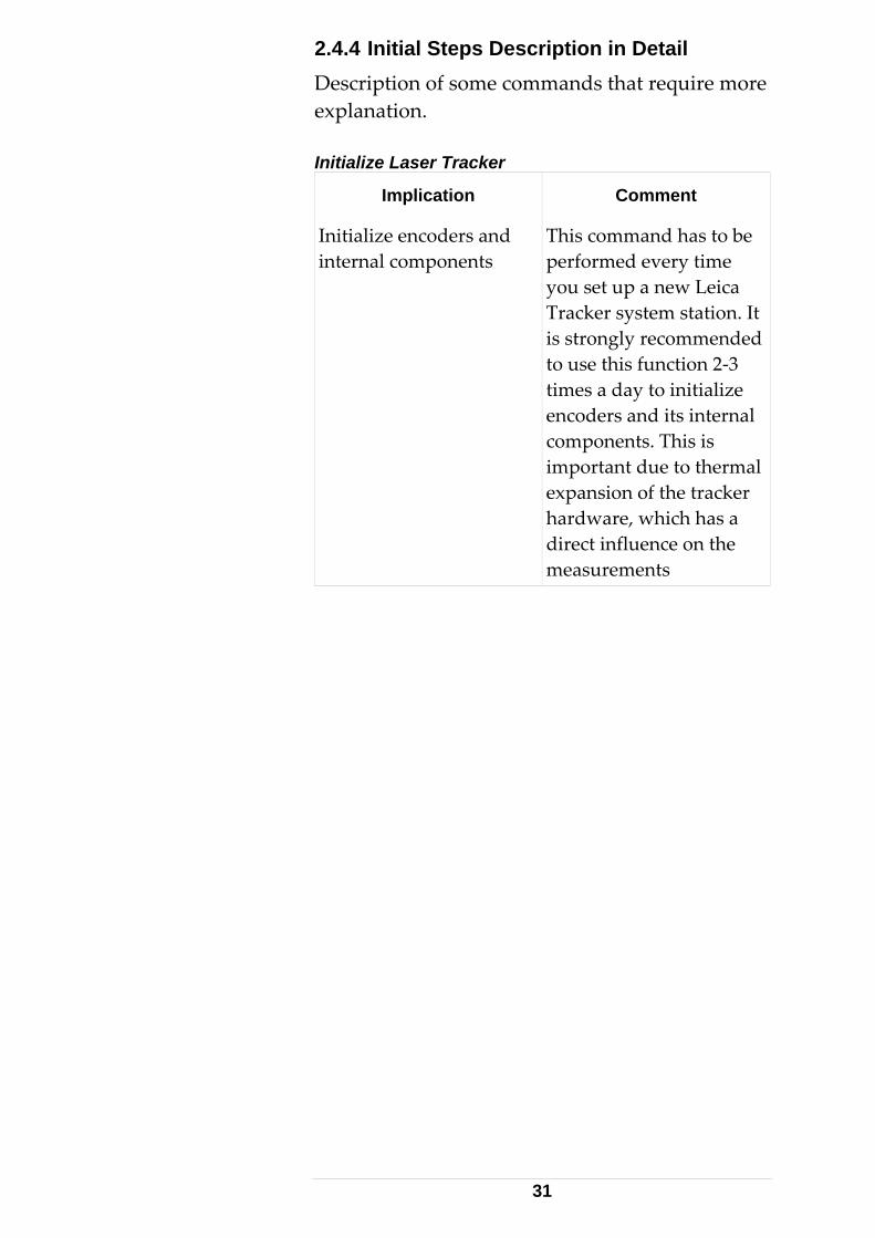
2.4.4 Initial Steps Description in Detail Description of some commands that require more explanation. Initialize Laser Tracker
Implication Comment
Initialize encoders and internal components
This command has to be performed every time you set up a new Leica Tracker system station. It is strongly recommended to use this function 2‐3 times a day to initialize encoders and its internal components. This is important due to thermal expansion of the tracker hardware, which has a direct influence on the measurements
31
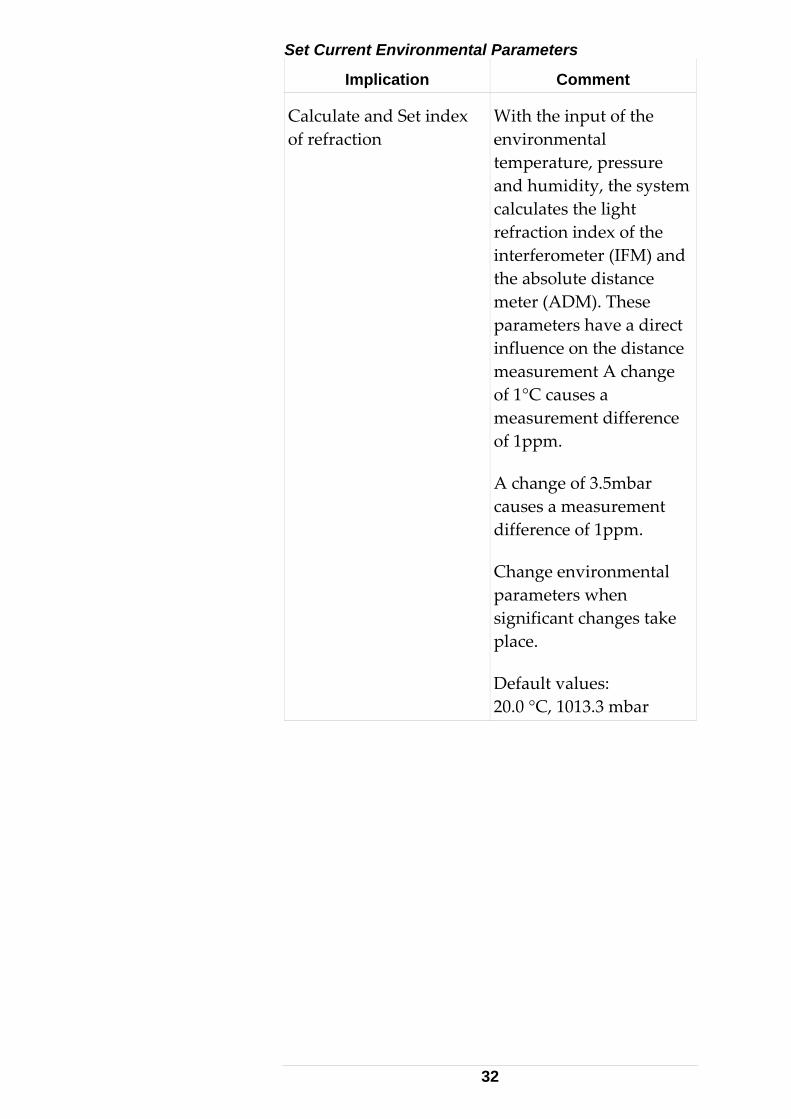
Set Current Environmental Parameters
Implication Comment
Calculate and Set index of refraction
With the input of the environmental temperature, pressure and humidity, the system calculates the light refraction index of the interferometer (IFM) and the absolute distance meter (ADM). These parameters have a direct influence on the distance measurement A change of 1°C causes a measurement difference of 1ppm.
A change of 3.5mbar causes a measurement difference of 1ppm.
Change environmental parameters when significant changes take place.
Default values: 20.0 °C, 1013.3 mbar
32
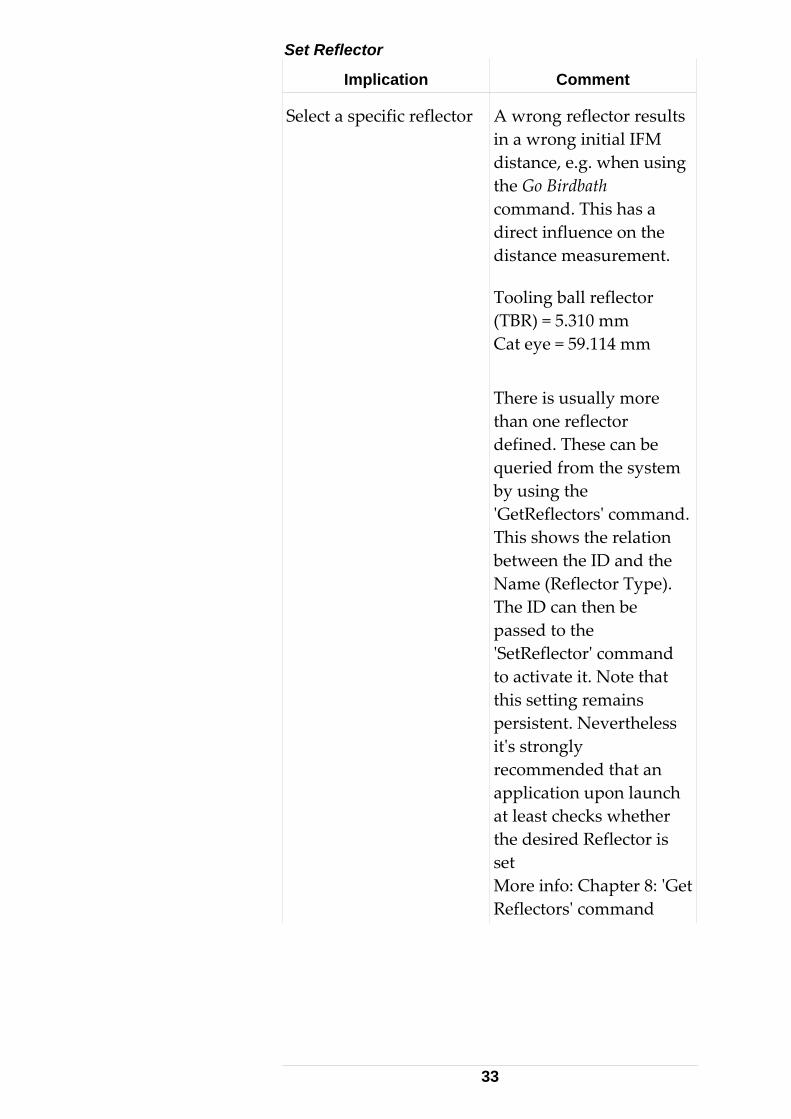
Set Reflector
Implication Comment
Select a specific reflector A wrong reflector results in a wrong initial IFM distance, e.g. when using the Go Birdbath command. This has a direct influence on the distance measurement.
Tooling ball reflector (TBR) = 5.310 mm Cat eye = 59.114 mm
There is usually more than one reflector defined. These can be queried from the system by using the ʹGetReflectorsʹ command. This shows the relation between the ID and the Name (Reflector Type). The ID can then be passed to the ʹSetReflectorʹ command to activate it. Note that this setting remains persistent. Nevertheless itʹs strongly recommended that an application upon launch at least checks whether the desired Reflector is set More info: Chapter 8: ʹGet Reflectorsʹ command
33
Set Compensation
Implication Comment
Select a specific Mechanical Tracker Compensation
More than one mechanical Tracker Compensation may be defined for a tracker (although often there is only one).
If there is more than one, these can be queried from the system by using the ʹGetCompensationsʹ command. This will show the relation between the ID (a number) and the Name (a Date‐ String) of the available compensation. The ID can then be passed to the ʹSetCompensationʹ command in order to activate it. Note that this setting remains persistent. Nevertheless, itʹs a good idea that an application upon launch at least checks whether the desired compensation is set (command GetCompensation). The principle of dealing with compensations is the same as for Reflectors. For more details see chapter 8: ʹGet Reflectorsʹ command
34
Set T- Cam To Tracker Compensation
Implication Comment
Select a specific T‐ Cam to Tracker Compensation. Related to 6DoF modes only.
More than one T‐ Cam to Tracker Compensation may be defined for a tracker/ camera (although often there is only one).
If there are more than one, these can be queried from the system by using the ʹGetTCamToTrackerCompensationsʹ command. This will show the relation between the ID (a number) and the Name (a Date‐ String) of the available compensation. The ID can then be passed to the ʹSetTCamToTrackerCompensationʹ command in order to activate it. Note that this setting remains persistent. Nevertheless, itʹs a good idea that an application upon launch at least checks whether the desired compensation is set (command ʹGetTCamToTrackerCompensationʹ). The principle of dealing with compensations is the same as for Reflectors. For more details see chapter 8: ʹGet Reflectorsʹ command
35
Set Probe Compensation
Implication Comment
Select a specific Probe Compensation. Related to 6DoF modes only.
More than one Probe Compensation may be defined for a tracker/ camera (although often there is only one).
If there is more than one, these can be queried from the system by using the ʹGetProbeCompensationsʹ command. This will show the relation between the ID (a number) and the Name (a Date‐ String) of the available compensation. The ID can then be passed to the ʹSetProbeCompensationʹ command in order to activate it. Note that this setting remains persistent. Nevertheless, itʹs a good idea that an application upon launch at least checks whether the desired compensation is set (command ʹGetProbeCompensationʹ)The principle of dealing with probe compensations is the same as for Reflectors. For more details see chapter 8: ʹGet Reflectorsʹ command
36
Keep Last Position Flag
Implication Comment
Makes the laser beam stay at its current position if the beam is broken.
Enabling this flag is optional for 3D measurements (it makes only sense if the Tracker is equipped with an ADM). This flag is cleared by default. For 6DoF measurements, enabling this flag is compulsory to prevent the laser going to home position upon a beam break.
(Automatically re‐measures reference distance to the Reflector or T‐Probe after the laser beam has been lost.)
There are two ways to control this flag, either through the command ‘SetSystemSettings’ or through ‘SetLongSystemParameter’
37
Station Parameters
Implication Comment
Orientation parameters can be determined using the Transformation functionality of emScon (see chapter ʹPoints to points Transformationʹ) or can be individually set by the application.
The station parameters describes the translation and rotation of the tracker station in a coordinate system: X, Y, Z, Omega, Phi, Kappa
By default, the orientation parameters are as follows: (X=0/Y=0/Z=0/Omega=0/Phi=0/Kappa=0).
Transformation Parameters
Implication Comment
Transformation parameters can be determined using the Transformation functionality of emScon (see chapter ʹPoints to points Transformationʹ) or can be individually set by the application.
A transformation describes a change into another coordinate system, which is different from the tracker coordinate system. It has the following parameters:X, Y, Z, Omega, Phi, and Kappa and scale factor.
By default, the transformation parameters are as follows: (X=0 / Y=0 / Z=0 / Omega=0 / Phi=0 / Kappa=0 / Scale = 1.
38
Coordinate System Type
Implication Comment
Selects the coordinate system type: RHR/LHR X, LHR Y, LHR Z/CCW/CCC/SCW/SCC
The TPI delivers the data in the current coordinate system type. By default the tracker system will work in the right handed rectangular coordinate system (RHR) type:
3D rectangular coordinates are defined by 3 mutually perpendicular axes X, Y and Z given in the order (X, Y, Z).
Since the axes can be arranged in two different ways, right and left‐handed systems are defined according to the convention illustrated in a simple 2D case.
Cylindrical Clockwise (CCW), Cylindrical Counter Clockwise (CCC). In a cylindrical system, the X and Y values are expressed in terms of a radial (distance) offset from the Z‐axis and a horizontal angle of rotation. The Z coordinate remains the same.
39
Implication Comment
Spherical Clockwise (SCW), Spherical Counter Clockwise (SCC). In a spherical system, a point is located by a distance and two angles instead of the 3 coordinate values along the rectangular axes. For axes labeled XYZ, with Z vertical, the point is located by its distance from the origin, horizontal angle in the XY plane and zenith angle measured from the Z‐axis.
2.4.5 Automatic External Device Recognition This is an improved new feature that comes with emScon version 3.0 (except for systems running on external emScon servers). This subject applies to so‐called ʹexternal devicesʹ (Meteo Station, Overview Camera, Inclination Sensor [Nivel]). In former versions, it was necessary to explicitly enable these devices by setting related flags ([hasVideoCamera, hasNivel, weatherMonitorStatus]) on using the ʹSetSystemSettingsʹ or ʹSetLongSystemParameterʹ command. See chapter about struct SystemSettingsDataT for details. In order to keep backward compatibility, these commands/flags still exist and will behave in a way that should not cause any problems to existing applications, although their behavior has slightly changed. Here is a description of the new automatic device recognition behavior:
40
• General Behavior When the system is initialized any device that is currently plugged in will be recognized and set accordingly. If the operator forgot to plug something in prior to initializing, he can simply connect it and re‐initialize the system to find the device.
• OVC Recognition During initialization the system will check to see if an Overview Camera (OVC) is attached. If yes, then the flag will be set to true, and communication should start to the device. If the operator (application) tries to set the flag false after the system has set it as true, then the system should allow it and end communication to the device, but will reset the flag and communication correctly on the next initialization. If the system sets the flag to false, but the operator (application) tries to force it to true, then the system should check to see if an OVC is attached before it allows the flag to be set as requested.
• Inclination Sensor [Nivel] Recognition During initialization the system will check to see if a NIVEL is attached. If yes, then the flag will be set to true, and communication should start to the device. If the operator (application) tries to set the flag false after the system has set it as true, then the system should allow it and end communication to the device, but will reset the flag and communication correctly on the next initialization. If the system sets the flag to false, but the operator (application) tries to force it to true, then the system should check to see if
41
a NIVEL is attached before it allows the flag to be set as requested.
• Meteo Station Recognition During initialization the system will check to see if a Meteo Station is attached. If yes, then the flag will be set to true, and ʹReadAndCalculateRefractionsʹ should start. If the operator (application) wants to switch to ʹReadOnlyʹ this will have to be done through the appropriate command. If the operator tries to set the flag false after the system has set it as true, then the system should allow it and end communication to the device, but will reset the flag and communication correctly on the next initialization. If the system sets the flag to false, but the operator (application) tries to force it to true, then the system should check to see if a Meteo Station is attached before it allows the flag to be set and ʹReadAndCalculateRefractionsʹ to start as requested.
Note that this automatic device recognition feature is not supported by external emScon servers – these still follow the ‘old’ behavior.
42
3 C - Interface
3.1 Low-level TPI Programming 3.1.1 Preconditions Using the C interface requires some particular C‐ programming knowledge. A programmer should at least know about asynchronous programming concepts, TCP/IP socket programming and multi‐threading.
The description of the enums and structs in this chapter sometimes may be slightly discrepant to the contents of the ʹES_C_API_Def.hʹ file. In such cases, the information in the ʹES_C_API_Def.hʹ file should be regarded as correct.
This chapter completely and exclusively relates to the file ʹES_C_API_Def.hʹ, which is part of the EmScon SDK. All Enumeration types and Structures are described in this header file. This header file acts as an integral part to this manual and it might be helpful to have it open in parallel to this document since the information is much more condensed there. 3.1.2 Recommendation Although the C‐ interface makes up the native programming‐ interface to emScon, it is not usually recommended to write applications directly using the C‐ interface. Rather use the much more convenient C++ (or C# or COM) interface. In contrast to the C++ interface, the C‐interface requires much more coding lines and comprises
43
the danger of doing initialization errors for structures (aka ʹcopy/paste errorsʹ). However, since itʹs the native interface, the enumeration types and structures of the C‐ interface serve as main‐ reference. The same enumeration types and parameters will show up ‐ in slightly different contexts with slightly different terminology ‐ in the other interfaces as well. Hence, even when working with the C++‐ interface (or C#, COM), looking up information in this chapter ʹC‐ Interfaceʹ might be essential. 3.1.3 Byte Alignment Data packets have a 4‐Byte alignment convention. The VC++ statement #pragma pack (push, 4), before user‐defined structure definition, uses 4 Byte alignment – VC++ default is 8 Byte. The statement #pragma pack (pop) sets the alignment back to the previous value.
Use only 4 Byte alignments for TPI structures.
These are Microsoft VC++ specific statements. When using a non‐Microsoft compiler, #pragma pack (push, 4) and pragma pack (pop) may have to be replaced by appropriate directives.
The following include statement prepares the C_API_Def.h file for Byte alignment in Linux/ Win32.
4 Byte alignments for other platforms must be forced #ifdef _WIN32 #pragma pack (push, 4) #elif defined __linux__ #pragma pack (4) #elif #error Insert here directive to ensure 4 Byte alignment for other platforms (Unix, MAC) #endif
3.1.4 Little/Big Endians Non‐Intel based workstations, for example M68000 based workstations like SUN, Apple or
44
IBM RS6000 series, use different endians for double values. The client application (the TCP/IP communication interface respectively) requires appropriate measures to interpret numerical values correctly.
The Tracker Server is Intel based. All values are provided in the little endian format. 3.1.5 Preprocessor Statements The following statements show a common practice to avoid multiple inclusion of the same include‐file while compiling a .CPP module. In case of nested inclusion of the ES_C_API_Def.h file, these statements will prevent warnings for multiple definitions of data types. #ifndef ES_C_API_DEF_H #define ES_C_API_DEF_H … #endif
3.1.6 TPI 'Boolean' Data Type No native Boolean data‐type is available in C. C uses the integer basic type for Boolean values. For convenience, a platform‐ independent ES_BOOL type has been introduced for the ES_API: typedef int ES_BOOL
Neither BOOL (which is 2 Bytes and Microsoft‐specific) nor bool (which is 1 Byte and specific to newer C++ revisions) has been used. By using a 4 Byte Boolean (= int), pure C compliance and maximal portability is assured.
This relates only to the C interface, ES_C_API_Def.h. The C++ interface as well as custom programs may use any compatible Boolean type. Boolean type variables used in ES C API structs must be 4 bytes.
45
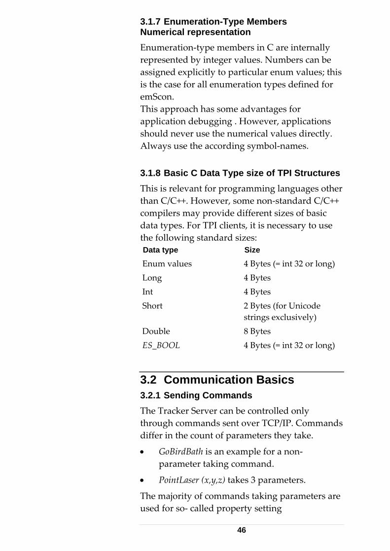
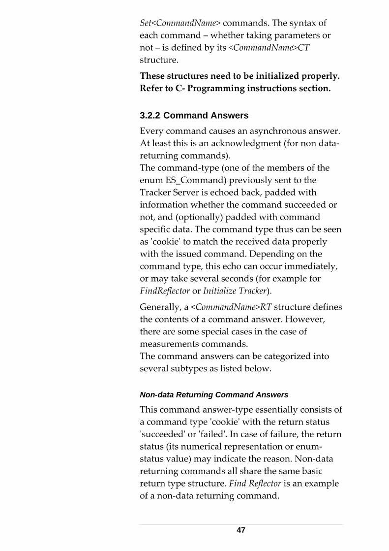
3.1.7 Enumeration-Type Members Numerical representation Enumeration‐type members in C are internally represented by integer values. Numbers can be assigned explicitly to particular enum values; this is the case for all enumeration types defined for emScon. This approach has some advantages for application debugging . However, applications should never use the numerical values directly. Always use the according symbol‐names. 3.1.8 Basic C Data Type size of TPI Structures This is relevant for programming languages other than C/C++. However, some non‐standard C/C++ compilers may provide different sizes of basic data types. For TPI clients, it is necessary to use the following standard sizes: Data type Size
Enum values 4 Bytes (= int 32 or long) Long 4 Bytes Int 4 Bytes Short 2 Bytes (for Unicode
strings exclusively) Double 8 Bytes
4 Bytes (= int 32 or long) ES_BOOL
3.2 Communication Basics 3.2.1 Sending Commands The Tracker Server can be controlled only through commands sent over TCP/IP. Commands differ in the count of parameters they take.
• GoBirdBath is an example for a non‐parameter taking command.
• PointLaser (x,y,z) takes 3 parameters.
The majority of commands taking parameters are used for so‐ called property setting
46
Set<CommandName> commands. The syntax of each command – whether taking parameters or not – is defined by its <CommandName>CT structure.
These structures need to be initialized properly. Refer to C‐ Programming instructions section. 3.2.2 Command Answers Every command causes an asynchronous answer. At least this is an acknowledgment (for non data‐ returning commands). The command‐type (one of the members of the enum ES_Command) previously sent to the Tracker Server is echoed back, padded with information whether the command succeeded or not, and (optionally) padded with command specific data. The command type thus can be seen as ʹcookieʹ to match the received data properly with the issued command. Depending on the command type, this echo can occur immediately, or may take several seconds (for example for FindReflector or Initialize Tracker).
Generally, a <CommandName>RT structure defines the contents of a command answer. However, there are some special cases in the case of measurements commands. The command answers can be categorized into several subtypes as listed below. Non-data Returning Command Answers
This command answer‐type essentially consists of a command type ʹcookieʹ with the return status ʹsucceededʹ or ʹfailedʹ. In case of failure, the return status (its numerical representation or enum‐status value) may indicate the reason. Non‐data returning commands all share the same basic return type structure. Find Reflector is an example of a non‐data returning command.
47
Property-data Returning Command Answers
Properties are the (current) system settings of the Tracker Server. Properties can be retrieved by Get<xxx> commands. All Get<xxx> commands return their results in a Get<xxx>RT structure. The RT structure for each command differs with respect to its data members. Data members with only a Get… with no corresponding Set… command can be individual basic‐type or enum parameters (int, double , enum...) . Example: GetSystemStatusRT. However, the normally there is a command‐specific sub structure (example GetUnitsRT contains a SystemUnitsDataT sub structure). In other words: a sub‐ structure is available, when the same parameters are used for more than one command. This avoids code duplication.
Set/Get commands rarely fail. If a Set command fails (return status not OK), the supplied parameters are usually out of valid range. The return status informs about the failure reason. Single Measurement Answers
These are answers that follow to a previously issued Start<xxx>MeasurementCT command. Single measurements are often also referred to as Stationary measurements. This applies only when the measurement mode is set to stationary.
• In case of a failure (which is frequent for measurement commands), a Start<xxx>MeasurementRT structure with the error code is returned.
• In case of success, instead of a Start<xxx>MeasurementRT (not designed to take sensor results), a specifically designed measurement type‐related data packet is received. For example, a
48
ES_DT_SingleMeasResult type indicates a SingleMeasResultT structure, and ES_DT_StationaryProbeMeasResult indicates arrival of a ProbeStationaryResultT. A successful measurement always returns such a data‐packet.
Multi-Measurement Answers
These apply to tracker related continuous measurements only. The measurement mode is set to one of the non‐ stationary modes.
• In case of failure, as with single measurement answers, a Start<xxx>MeasurementRT with error code is returned.
• In case of success, not only one packet, but also a series of multi‐measurement packets arrive. Each one of these packets contains a various‐sized array of ʹsingleʹ (atomic) measurements. See also structures ʹMultiMeasResultTʹ, ʹMultiMeasResult2Tʹ and ʹProbeContinuousResultTʹ.
• Only the first element of the measurement array is covered by these structures, although the index is valid from 0…numberOfResults‐1. There is another significant difference to single measurements. Before the measurement data packet stream starts, a StartMeasurementRT with command status OK arrives (acknowledge that the ‘start’ command has arrived).
• Single measurement results always arrive within a certain time span. This is not the case with continuous measurements (Grid Mode, big time separation criteria.). A StartMeasurementRT confirmation is therefore essential for continuous modes.
49

A multi‐measurement stream runs until explicitly stopped, StopMeasurement or until specified time or count thresholds are reached.
Special Command Answers
Some commands, such as ES_C_GetReflectors and ES_C_GetTransformedPoints, ES_C_GetCompensations, ES_C_GetTipAdapters. do not fit any of the above categories. Generally spoken, all commands starting with ʹGetʹ and ending with an ʹsʹ (i.e. plural) are treated in a special way.
ES_C_GetReflectors must not to be mixed up with ES_C_GetReflector (missing ʹsʹ).
Convention:
The answer to these commands is made up of as many answer‐packets as reflector types (or transformed points, Compensations, Tips...) are available from the Tracker Server. These answers mainly resolve the relation between item name (string) and item ID (numerical ID), for example the relation between Reflector name and Reflector ID. Apart from different other information, the packets also contain (redundant) information on the total number of items and the number of packets expected to arrive.
Convention:
All string‐type names are in Unicode representation – Example: short cReflectorName[32] declaration. It can consist of a maximum of 32 characters, however, since ʹshortʹ is 16 bit, there are 16 bits for every character (two Bytes).
50
ReflectorPosResultT and ProbePosResultT can also be seen as a special command answers. These are ES_DT_ReflectorPosResult / ES_DT_ProbePosResult type packets and are received whenever the tracker is locked onto a reflector (3 measurements per second), supposed the ʹSendReflectorPositionDataʹ system‐ setting flag is enabled. This mechanism can be used in applications providing graphical representation of reflector/probe motion, even while no continuous measurement is in ongoing. Note that the accuracy of the positions provided are limited. The receipt of these measurements can be switched on/off. It is switched off by default. 3.2.3 Error Events Most error‐type data packets ES_DT_Error are not direct reactions to commands. They are ʹunsolicitedʹ and can occur at any time. These confirm the highly ʹasynchronousʹ behavior of emScon communication. A typical example is the ʹLaser beam brokenʹ event.
Commands contain the error status in their answer structure in case of failure. ES_DT_Errors type answer packets are only used for so called ʹunsolicited errorsʹ (which can occur at any time, regardless of a command). 3.2.4 System Status Change Events Although already present in version 1.2 (only two events), there has been an inflation of such events since then. The appropriate packet type is ES_DT_SystemStatusChange. The handling is the same as with error events, with the only difference that there is only one parameter.
IMPORTANT: See chapter ʹVersion Backward Compatibilityʹ for convention about handling
51
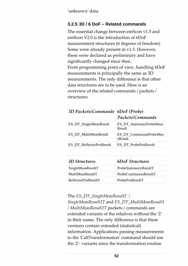
ʹunknownʹ data. 3.2.5 3D / 6 DoF – Related commands The essential change between emScon v1.5 and emScon V2.0 is the introduction of 6DoF measurement structures (6 degrees of freedom). Some were already present in v1.5. However, these were declared as preliminary and have significantly changed since then. From programming point of view, handling 6DoF measurements is principally the same as 3D measurements. The only difference is that other data structures are to be used. Here is an overview of the related commands / packets / structures:
3D Packets/Commands 6DoF (Probe) Packets/Commands
ES_DT_SingleMeasResult ES_DT_StationaryProbeMeasResult
ES_DT_MultiMeasResult ES_DT_ContinuousProbeMeasResult
ES_DT_ReflectorPosResult ES_DT_ProbePosResult
3D Structures 6DoF Structures SingleMeasResultT ProbeStationaryResultT MultiMeasResultT ProbeContinuousResultT ReflectorPosResultT ProbePosResultT
The ES_DT_SingleMeasResult2 / SingleMeasResult2T and ES_DT_MultiMeasResult2 / MultiMeasResult2T packets / commands are extended variants of the relatives without the ʹ2ʹ in their name. The only difference is that these versions contain extended (statistical) information. Applications passing measurements to the ʹCallTransformationʹ command should use the ʹ2ʹ‐ variants since the transformation routine
52
requires these extended statistics. See also ʹSetStatisticModeʹ command.
3.3 C- Language TPI Reference 3.3.1 Constants This section names the constants that can be used with C/C++ TPI programming.
The application needs to include the file ʹConstant.hʹ in addition to ʹES_C_API_Def.hʹ.
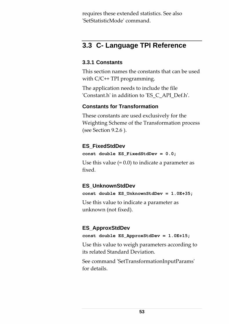
Constants for Transformation These constants are used exclusively for the Weighting Scheme of the Transformation process (see Section 9.2.6 ). ES_FixedStdDev const double ES_FixedStdDev = 0.0;
Use this value (= 0.0) to indicate a parameter as fixed. ES_UnknownStdDev const double ES_UnknownStdDev = 1.0E+35;
Use this value to indicate a parameter as unknown (not fixed).
ES_ApproxStdDev const double ES_ApproxStdDev = 1.0E+15;
Use this value to weigh parameters according to its related Standard Deviation.
See command ʹSetTransformationInputParamsʹ for details.
53
Other Constants
The other constants defined in ʹConstant.hʹ (Unit‐Conversion related constants) are for informational reasons only and should not be directly referenced by emScon applications. 3.3.2 Enumeration Types This section describes all enumeration types and their individual values. ES_DataType
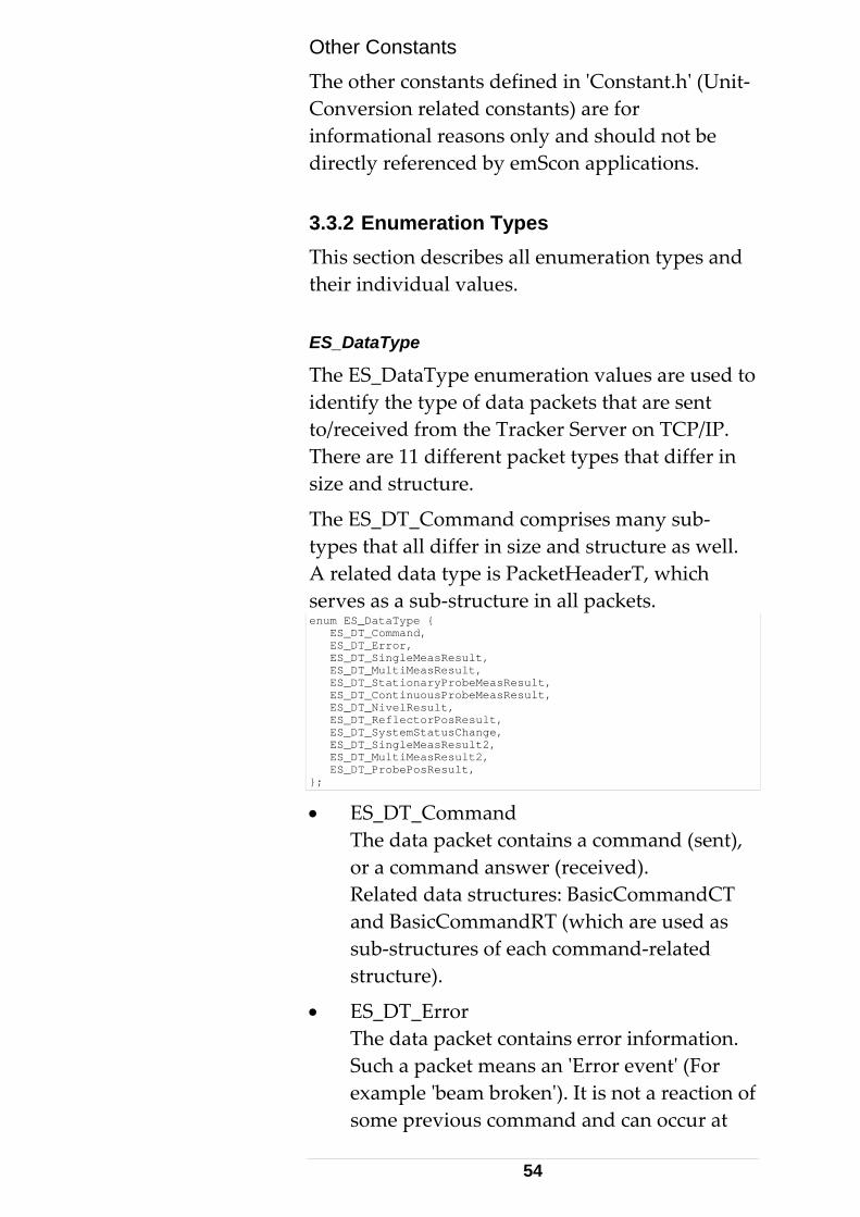
The ES_DataType enumeration values are used to identify the type of data packets that are sent to/received from the Tracker Server on TCP/IP. There are 11 different packet types that differ in size and structure.
The ES_DT_Command comprises many sub‐types that all differ in size and structure as well. A related data type is PacketHeaderT, which serves as a sub‐structure in all packets. enum ES_DataType { ES_DT_Command, ES_DT_Error, ES_DT_SingleMeasResult, ES_DT_MultiMeasResult, ES_DT_StationaryProbeMeasResult, ES_DT_ContinuousProbeMeasResult, ES_DT_NivelResult, ES_DT_ReflectorPosResult, ES_DT_SystemStatusChange, ES_DT_SingleMeasResult2, ES_DT_MultiMeasResult2, ES_DT_ProbePosResult, };
• ES_DT_Command The data packet contains a command (sent), or a command answer (received). Related data structures: BasicCommandCT and BasicCommandRT (which are used as sub‐structures of each command‐related structure).
• ES_DT_Error The data packet contains error information. Such a packet means an ʹError eventʹ (For example ʹbeam brokenʹ). It is not a reaction of some previous command and can occur at
54
any time. Related data structure: ErrorResponseT.
• ES_DT_SingleMeasResult The data packet contains the result of one single (stationary 3D) measurement. ʹResultʹ‐ type packets can only be received. Related data structure: SingleMeasResultT.
• ES_DT_MultiMeasResult The data packet contains results of a continuous 3D measurement. This type of result block is of variable size and depends on the number of single measurements within a block. ʹResultʹ‐ type values can only be received. Related data structure: MultiMeasResultT.
• ES_DT_StationaryProbeMeasResult The equivalent to SingleMeasResult, but with 6 degrees of freedom, i.e. the data block contains 3 angular values in addition to 3 coordinate values (apart from other data). Related data structure: ProbeStationaryResultT.
• ES_DT_ContinuousProbeMeasResult The equivalent to MultiMeasResult, but with 6 degrees of freedom, that is, the data block contains measurements each with 3 rotation parameters in addition to 3 coordinate position values (apart from other data). Related data structure: ProbeContinuousResultT
• ES_DT_NivelResult The data packet contains the result of a Leica ʹNivelʹ sensor (inclination sensor) measurement. Requires a Leica ʹNivelʹ (inclination sensor of type ʹNivel20ʹ or ʹNivel230ʹ) being connected to the Tracker directly. ʹResultʹ‐type values can only be received. Related data structure: NivelResultT.
55
• ES_DT_ReflectorPosResult: The data packet contains position information about the reflector. This type of information is foreseen for special purposes and can be suppressed. Related data structure: ReflectorPosResultT.
• ES_DT_SystemStatusChange The data packet contains information about a status change. Other than an error event, a SystemStatusChange event does not mean a failure. Related data structure: SystemStatusChangeT.
• ES_DT_SingleMeasResult2 The data packet contains the result of one single (stationary) measurement, in case the statistic mode is set to ‘extended’. These types are mainly used for measurements used as input to the Transformation routine. See command ʹSetStatisticModeʹ. The difference is that SingleMeasResult2T contains more statistical information than the standard SingleMeasResultT. This is an advanced feature. The default statistic mode is ‘standard’. (This ʹtype 2 meas resultʹ has been introduced to avoid changes to already published TPI definitions with earlier versions, in order not to break existing applications. ). Related data structure: SingleMeasResult2T.
• ES_DT_MultiMeasResult2 The data packet contains results of a continuous measurement, in case the statistic mode is set to ‘extended’. See command ʹSetStatisticModeʹ. The difference is that MultiMeasResult2T contains more statistical information than the standard MultiMeasResultT.
56
The default statistic mode is ‘standard’. Related data structure: MultiMeasResult2T.
• ES_DT_ ProbePosResult The equivalent to ES_DT_ReflectorPosResult, but related to probes with 6 Degrees of freedom. I.e. Not only the position, but also the rotation is supplied.
ES_Command
This enumeration type names all commands that are provided by the TPI. A data packet of type ES_DT_Command contains exactly one of these values. The answer packet to a command returns the same value for acknowledgment. See struct ʹBasicCommandCTʹ for details.
General Information related to each command: 1.) Naming Convention Send / Receive Structs
The related data‐ structures for sending and receiving data can be derived from the command name as follows:
• Remove the ES_C_ Prefix from the command
• Add CT postfix to get name of related send‐ structure (CT stands for CommandType)
• Add RT postfix to get name of related receive‐ structure (RT stands for ReturnType)
Example: Structures related to command ʹES_C_Initializeʹ are ʹInitializeCTʹ and ʹInitializeRTʹ
If CT/RT structures contain sub‐ structs, these are mentioned at each commands description.
Explanations are available at the command descriptions (ES_C_...) and also at the related structure descriptions (..CT, ..RT). To avoid too much redundancy, descriptions are usually not repeated at both locations. Thus it might be
57
necessary to look‐ up command descriptions and related structure descriptions. 2.) Dimensions / Units of Parameters
Unless stated explicitly in the command description, the following units of all parameters are always in ʹcurrent unitsʹ. That is, in those units the application/programmer has selected with the SetUnits command:
‐ Length‐ units
‐ Angle‐ units
‐ Temperature‐ units
‐ Pressure‐ units
‐ Humidity‐ units (currently only one: percent)
This applies to parameters sent as well as those received such as coordinates, standard deviations, meteorological values...
• Currently, there is only one exception to this rule: The command StartNivelMeasurement delivers the native Nivel inclination readings. These are milli‐radiants and degrees Celsius, regardless of currently selected units.
• Other units include: ‐ Time – units: These are always in milliseconds – unless stated differently. Example: a Stationary Measurement Time of ʹ2000 ʹmeans two seconds.
• String‐ type parameters: Strings as far as handled through the TPI are always in UNICODE (arrays of unsigned short). That is, two bytes are reserved for each character. As far as pure ANSI text is used, an application can just ignore each second byte. See sample applications for examples.
• Enumeration‐type parameters: These are type‐safe with the related enum definition. The
58
parameters are described at the enum‐definition location.
3.) Valid Parameter Ranges
This applies to parameters being sent to the system, typically with one of the ʹSet..ʹ command. Where limitations apply, these are mentioned at the command description. See also chapter ʹWorking Conditionsʹ in the ʹIntroductionʹ main chapter of this manual. Note that it is never possible to violate valid parameter ranges in such that the related ʹSet..ʹ commands do not accept values outside valid range and therefore will return with an error. Reading Instructions Set/Get Command- pairs.
Information about parameter representation in terms of current Units, Coordinate System‐ Type (CS‐type), Transformation and Orientation is provided at the Description of the ʹSet..ʹ command, but not repeated at the description of the related ʹGet..ʹ command. It is obvious that these information apply to both ʹSet..ʹ and ʹGet..ʹ. (Although the valid range information is obsolete for ʹGet..ʹ commands).
59
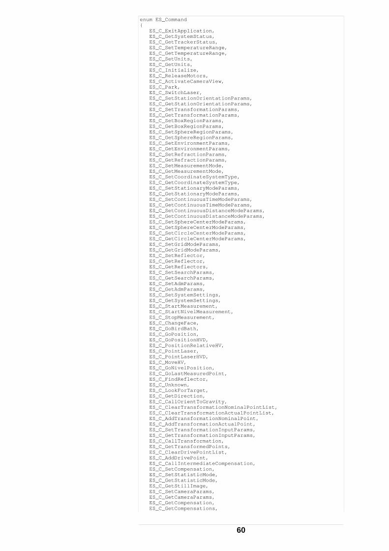
enum ES_Command { ES_C_ExitApplication, ES_C_GetSystemStatus, ES_C_GetTrackerStatus, ES_C_SetTemperatureRange, ES_C_GetTemperatureRange, ES_C_SetUnits, ES_C_GetUnits, ES_C_Initialize, ES_C_ReleaseMotors, ES_C_ActivateCameraView, ES_C_Park, ES_C_SwitchLaser, ES_C_SetStationOrientationParams, ES_C_GetStationOrientationParams, ES_C_SetTransformationParams, ES_C_GetTransformationParams, ES_C_SetBoxRegionParams, ES_C_GetBoxRegionParams, ES_C_SetSphereRegionParams, ES_C_GetSphereRegionParams, ES_C_SetEnvironmentParams, ES_C_GetEnvironmentParams, ES_C_SetRefractionParams, ES_C_GetRefractionParams, ES_C_SetMeasurementMode, ES_C_GetMeasurementMode, ES_C_SetCoordinateSystemType, ES_C_GetCoordinateSystemType, ES_C_SetStationaryModeParams, ES_C_GetStationaryModeParams, ES_C_SetContinuousTimeModeParams, ES_C_GetContinuousTimeModeParams, ES_C_SetContinuousDistanceModeParams, ES_C_GetContinuousDistanceModeParams, ES_C_SetSphereCenterModeParams, ES_C_GetSphereCenterModeParams, ES_C_SetCircleCenterModeParams, ES_C_GetCircleCenterModeParams, ES_C_SetGridModeParams, ES_C_GetGridModeParams, ES_C_SetReflector, ES_C_GetReflector, ES_C_GetReflectors, ES_C_SetSearchParams, ES_C_GetSearchParams, ES_C_SetAdmParams, ES_C_GetAdmParams, ES_C_SetSystemSettings, ES_C_GetSystemSettings, ES_C_StartMeasurement, ES_C_StartNivelMeasurement, ES_C_StopMeasurement, ES_C_ChangeFace, ES_C_GoBirdBath, ES_C_GoPosition, ES_C_GoPositionHVD, ES_C_PositionRelativeHV, ES_C_PointLaser, ES_C_PointLaserHVD, ES_C_MoveHV, ES_C_GoNivelPosition, ES_C_GoLastMeasuredPoint, ES_C_FindReflector, ES_C_Unknown, ES_C_LookForTarget, ES_C_GetDirection, ES_C_CallOrientToGravity, ES_C_ClearTransformationNominalPointList, ES_C_ClearTransformationActualPointList, ES_C_AddTransformationNominalPoint, ES_C_AddTransformationActualPoint, ES_C_SetTransformationInputParams, ES_C_GetTransformationInputParams, ES_C_CallTransformation, ES_C_GetTransformedPoints, ES_C_ClearDrivePointList, ES_C_AddDrivePoint, ES_C_CallIntermediateCompensation, ES_C_SetCompensation, ES_C_SetStatisticMode, ES_C_GetStatisticMode, ES_C_GetStillImage, ES_C_SetCameraParams, ES_C_GetCameraParams, ES_C_GetCompensation, ES_C_GetCompensations,
60
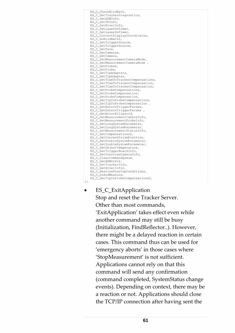
ES_C_CheckBirdBath, ES_C_GetTrackerDiagnostics, ES_C_GetADMInfo, ES_C_GetTPInfo, ES_C_GetNivelInfo, ES_C_SetLaserOnTimer, ES_C_GetLaserOnTimer, ES_C_ConvertDisplayCoordinates, ES_C_GoBirdBath2, ES_C_SetTriggerSource, ES_C_GetTriggerSource, ES_C_GetFace, ES_C_GetCameras, ES_C_GetCamera, ES_C_SetMeasurementCameraMode, ES_C_GetMeasurementCameraMode , ES_C_GetProbes, ES_C_GetProbe, ES_C_GetTipAdapters, ES_C_GetTipAdapter, ES_C_GetTCamToTrackerCompensations, ES_C_GetTCamToTrackerCompensation, ES_C_SetTCamToTrackerCompensation, ES_C_GetProbeCompensations, ES_C_GetProbeCompensation, ES_C_SetProbeCompensation, ES_C_GetTipToProbeCompensations, ES_C_GetTipToProbeCompensation , ES_C_SetExternTriggerParams, ES_C_GetExternTriggerParams , ES_C_GetErrorEllipsoid, ES_C_GetMeasurementCameraInfo, ES_C_GetMeasurementProbeInfo, ES_C_SetLongSystemParameter, ES_C_GetLongSystemParameter, ES_C_GetMeasurementStatusInfo, ES_C_GetCompensations2, ES_C_GetCurrentPrismPosition, ES_C_SetDoubleSystemParameter, ES_C_GetDoubleSystemParameter, ES_C_GetObjectTemperature, ES_C_GetTriggerBoardInfo, ES_C_GetOverviewCameraInfo, ES_C_ClearCommandQueue, ES_C_GetADMInfo2, ES_C_GetTrackerInfo, ES_C_GetNivelInfo2, ES_C_RestoreStartupConditions, ES_C_GoAndMeasure, ES_C_GetTipToProbeCompensations2, };
• ES_C_ExitApplication Stop and reset the Tracker Server. Other than most commands, ‘ExitApplication’ takes effect even while another command may still be busy (Initialization, FindReflector..). However, there might be a delayed reaction in certain cases. This command thus can be used for ‘emergency aborts’ in those cases where ‘StopMeasurement’ is not sufficient. Applications cannot rely on that this command will send any confirmation (command completed, SystemStatus change events). Depending on context, there may be a reaction or not. Applications should close the TCP/IP connection after having sent the
61
‘ExitApplication’ command. Note: ‘ExitApplication’ and ‘StopMeasurement’ are the only two exceptions of commands that cause immediate reaction while some other command is still pending. All other commands will return ‘Server busy instead’. (Hint: This does not apply to the synchronous emScon COM interface (LTControl)).
• ES_C_GetSystemStatus Request status information about the system.
• ES_C_GetTrackerStatus Request status information about the tracker.
• ES_C_SetTemperatureRange Set the Trackers working temperature range.
• ES_C_GetTemperatureRange Get the Trackers working temperature range.
• ES_C_SetUnits Set Current Units. All length, angular, temperature, pressure and humidity‐ type parameters of all TPI‐ commands are represented in the currently selected units. Exception: Leica ʹNivelʹ (inclination sensor) readings are provided in the sensors native units (milli‐rad, Celsius). Related structure: SystemUnitsDataT.
• ES_C_GetUnits Queries the currently active unit‐ settings. Related structure: SystemUnitsDataT.
• ES_C_Initialize Initializes the tracker.
• ES_C_ReleaseMotors Release the motor for horizontal and vertical tracker head movement in order to allow manual tracker head movement.
62
• ES_C_ActivateCameraView Activates the camera view. The mirror is turned upwards in order to direct camera view towards tracker head orientation. Command only applies to Trackers equipped with an overview camera.
• ES_C_Park Send tracker to park position. The laser beam points towards the floor on the opposite side of the Bird bath.
• ES_C_SwitchLaser Switch the laser off or on. Usually used to switch off the laser overnight.
• ES_C_SetStationOrientationParams Set the 6 orientation parameters to be applied to measurements and positioning coordinates. Invariant orientation parameters are {0,0,0,0,0,0}. With these default settings, the tracker delivers measured coordinate values (and takes positioning values) in the instrumentʹs CS. Orientation parameters values are also ignored if the applyStationOrientationParams system settings flag is not set. Station orientation parameters itself are in current units and current CS‐type, but neither according to applied transformation settings nor to applied orientation settings (which would mean recursive). No range limitations apply. Related structure: StationOrientationDataT.
• ES_C_GetStationOrientationParams Queries the currently applied 6 orientation parameters. Related structure: StationOrientationDataT.
• ES_C_SetTransformationParams Set the 7 transformation parameters to be applied to measurements and positioning coordinates and to (part of) the input filters
63
such as region parameters. Invariant transformation parameters are {0,0,0,0,0,0,1}. With these default settings, the tracker delivers data in the instrumentʹs CS, (or in the ʹoriented systemʹ, if non‐invariant orientation parameters are present). Transformation parameters are also ignored if the applyTransformationParams system settings flag is not set. Transformation parameters itself are in current units and current CS‐type, but neither according to applied orientation settings nor to applied transformation settings (which would mean recursive)! No range limitations apply. Related structure: TransformationDataT.
• ES_C_GetTransformationParams Queries the currently applied 7 transformation parameters. Related structure: TransformationDataT.
• ES_C_SetSphereRegionParams Defines a spherical region. If the corresponding mode is active, measurements outside the region are suppressed. The interpretation of the parameters is subject to units, coordinate type, and transformation parameters. Related structure: SphereRegionDataT
• ES_C_GetSphereRegionParams Queries the currently valid sphere region parameters. Related structure: SphereRegionDataT.
• ES_C_SetBoxRegionParams Defines a box region. If the corresponding mode is active, measurements outside the region are suppressed. The box is connected to the object system given by the transformation parameters. It is defined by its diagonal, i.e. by two points in the object
64
system. The coordinates of the points are subject to units and coordinate type (They are NOT subject to transformation parameters!) A box region is described by a coordinate system parallel to the box edges and two opposite vertices. All coordinates of the first point must be less than those of the second one. If this condition fails on input, the corresponding coordinates are switched. Related structure: BoxRegionDataT.
• ES_C_GetBoxRegionParams Queries the currently valid box region parameters. Note that the retrieved point coordinate values can be different from those previously set by SetBoxRegion (Because of the condition that the coordinates of the first point must be less than those of the second one). However, the defined box will remain the same. Related structure: BoxRegionDataT.
• ES_C_SetEnvironmentParams Sets the environment parameters. (Temperature, pressure and humidity). Parameters are in current units. For valid parameter ranges, refer to chapter ʹWorking Conditionsʹ in the ʹIntroductionʹ main chapter of this manual. Trying to set values outside the valid ranges will result in command failure. Related structure: EnvironmentDataT. See enum ʹES_WeatherMonitorStatusʹ for details on explicit and implicit updates of environmental parameters. Like for any ʹSet...ʹ command, a ʹStatus Change Eventʹ is thrown, supposed the change exceeds the currently valid threshold. In this case, it will be
65

ʹES_SSC_EnvironmentParamsChangedʹ event.
• ES_C_GetEnvironmentParams Queries the currently valid environment parameters. Related structure: EnvironmentDataT. See enum ʹES_WeatherMonitorStatusʹ for details on explicit and implicit updates of environmental parameters.
• ES_C_SetRefractionParams Set explicit Refraction Indices for Interferometer and ADM. This is an advanced command and should only be used in real special situations. That is, if one wants to use his own formula for calculating the refractions from the environment parameters. SetRefractionParams will override those refraction parameters indirectly calculated and implicitly set by a previous call to SetEnvironmentParams. Note SetEnvironmentParams and SetRefractionParams are ʹconcurrentʹ commands. Both update the refraction parameters. Refraction indices are dimension‐less. For valid parameter ranges refer to chapter ʹWorking Conditionsʹ in the ʹIntroductionʹ main chapter of this manual. Trying to set values outside the valid ranges will result in command failure. A change of the environment parameters automatically causes an internal, implicit refraction parameter setting.
• ES_C_GetRefractionParams Query the currently valid Refraction Parameters for Interferometer and ADM.
• ES_C_SetMeasurementMode Sets the measurement mode of the tracker. Depending on this mode, a subsequent ʹStart
66
measurementʹ command will result in a ʹStationary measurementʹ (=single point measurement), a ʹContinuous measurementʹ etc. See enum ʹES_MeasModeʹ for a list of modes supported.
• ES_C_GetMeasurementMode Queries the currently active measurement mode.
• ES_C_SetCoordinateSystemType Sets the coordinate system type. See ʹES_CoordinateSystemTypeʹ for a list of CS‐ types supported. All coordinate‐ type parameters of all TPI commands are represented in the currently selected CS‐type.
• ES_C_GetCoordinateSystemType Queries the currently active CS‐type.
• ES_C_SetStationaryModeParams Sets the properties for a stationary measurement, i.e. Measurement time and ADM use (usually do not use ADM upon measurement). Measurement time must lie between 500 ms and 100000 ms (0.5 – 100 seconds). Related structure: StationaryModeDataT.
• ES_C_GetStationaryModeParams Queries the currently valid Stationary Mode Parameters. Related structure: StationaryModeDataT.
• ES_C_SetContinuousTimeModeParams Sets the properties for a continuous time measurement. Related structure: ContinuousTimeModeDataT.
• ES_C_GetContinuousTimeModeParams Queries the currently valid Continuous Time
67
Mode Parameters Related structure: ContinuousTimeModeDataT.
• ES_C_SetContinuousDistanceModeParams Sets the properties for a continuous distance measurement. Distance parameter is in current Length‐ units. No range limitation applies to distance parameters in theory, but there is a practical limitation given by tracker working space. Related structure: ContinuousDistanceModeDataT.
• ES_C_GetContinuousDistanceModeParams Queries the currently valid Continuous Distance mode parameters. Related structure: ContinuousDistanceModeDataT.
• ES_C_SetSphereCenterModeParams Sets the properties for a Sphere Center measurement. Radius and SpatialDistance parameters are in current Length‐ units. No range limitation apply to distance and radius parameters in theory, but there is a practical limitation given by tracker working space. Related structure: SphereCenterModeDataT.
• ES_C_GetSphereCenterModeParams Queries the currently valid SphereCenterMode Parameters. Related structure: SphereCenterModeDataT.
• ES_C_SetCircleCenterModeParams Set the properties for a Circle Center measurement. Radius and SpatialDistance parameters are in current Length‐ units. No range limitation apply to distance and radius parameters in theory, but there is a practical limitation given by tracker working space. Related structure: CircleCenterModeDataT.
68
• ES_C_GetCircleCenterModeParams Queries the currently valid Circle Center Mode Parameters. Related structure: CircleCenterModeDataT.
• ES_C_SetGridModeParams Sets the properties for a Grid measurement. Grid value parameters are in current units, and according current CS‐type. No range limitation apply to grid parameters in theory, but there is a practical limitation given by tracker working space. Related structure: GridModeDataT.
• ES_C_GetGridModeParams Queries the current Grid Mode Parameters. Related structure: GridModeDataT.
• ES_C_SetReflector Sets the valid reflector type by its numerical ID. Attention: Reflector IDʹs must not be hard coded. They differ from emScon system to emScon system. Use command ʹGetReflectorsʹ to query the system for defined reflectors and appropriate ID‐name/type mapping.
• ES_C_GetReflector Queries the ID of currently valid Reflector .
• ES_C_GetReflectors Queries all known reflectors of the Tracker Server. Apart from other information, mainly delivers the association between reflector names and their numerical IDs.
• ES_C_SetSearchParams Set criteria for reflector search abort (search radius and time out). Search radius is in current Length‐ units. Maximal search parameter is 0.5 meters. The search time should be set into a reasonable relation to the search radius. Large search radii result in extended search
69
times unless limited by the search timeout value. The minimum value for the SearchTimeout is 10’000 ms (10 seconds); the maximum is 240ʹ000 ms (4 minutes).
Related structure: SearchParamsDataT. For a detailed description see there.
• ES_C_GetSearchParams Queries the currently valid criteria for aborting a reflector search. Related structure: SearchParamsDataT. For detailed description see there.
• ES_C_SetAdmParams Set parameters for the ADM (stability, time, retries). Attention: This is a ʹdangerousʹ command. Lowering the stability criteria will result in measurement precision loss. Only change these values if really required due instable conditions (ground vibrations etc.) TargetStabilityTolerance is a distance parameter and is in current length‐ units. TargetStabilityTolerance must lie between 0.005 and 0.1 Millimeter. Leave this value as low as possible! (Default is 0.005). RetryTimeFrame is in milliseconds in the range between 500 and 5000. Related structure: AdmParamsDataT.
• ES_C_GetAdmParams Queries the currently valid ADM parameters. Related structures: SetAdmParamsCT, SetAdmParamsRT and AdmParamsDataT.
• ES_C_SetSystemSettings Sets system settings, a collection of flags to control the behavior of Tracker Server. See struct ʹSystemSettingsDataTʹ for details. Related structures: SetSystemSettingsCT, SetSystemSettingsRT and SystemSettingsDataT .
70
• ES_C_GetSystemSettings Queries the currently valid System Settings. Related structure: SystemSettingsDataT.
• ES_C_StartMeasurement Triggers a measurement – regardless of the measurement mode. I.e. depending on selected mode, Start Measurement may start a Stationary3D‐ a StationaryProbe‐, a Continuous3D‐ or a ContinuousProbe measurement. Once a continuous measurement (with unlimited time/points) has been started, it can only be stopped on using ES_C_StopMeasurement (apart from beam break). Note: ‘StopMeasurement’ can also be used to interrupt some other lengthily taking (but deterministic) commands (Except on using the emScon COM [LTControl] synchronous interface – See Chapter ‘Proper Interface Selection’). Further details see description of ‘ES_C_StopMeasurement’.
• ES_C_StartNivelMeasurement Triggers a Leica ʹNivelʹ (inclination sensor) measurement, if sensor is available. Note: result are in native Nivel units (milli‐ radiant, Celsius), regardless of the currently set angular and temperature units. This is an exception to the common convention. Reason: It does not make sense to provide very small angles (parts of milli‐ radiants) in Degrees or Gons.
• ES_C_StopMeasurement Stopping a continuous measurement is the main purpose of this command. However, this command can also be used to interrupt other long taking, but deterministic actions (This is a new feature introduced with V2.0 and is not available on earlier
71
emScon versions). Commands that can be interrupted include: Stationary Measurements (if a long measurement time is applied), those Positioning Commands including a spiral reflector search (GoPosition, FindReflector..), and finally the ‘OrientToGravity’ and ‘Automated Intermediate Compensation’ processes. Note: the Tracker ‘Initialize’ command cannot be interrupted. Interruption of long taking commands is also not possible when using the emScon COM [LTControl] synchronous interface. If an issue, use the asynchronous COM interface. For details see chapter ‘Proper Interface Selection’.
• ES_C_ChangeFace Changes the tracker face before the laser beam is attached to the same position.
• ES_C_GoBirdBath 3D Modes: Laser beam is sent to the Bird bath. The beam is ʹattachedʹ to the reflector in the Bird bath and the Interferometer distance is set to the known Bird‐ bath distance. This command is especially important for LT‐ series trackers without ADM. For such tracker, there is no other way to set the interferometer distance. 6D Modes: GoBirdBath does not make sense for a Probe. This command thus has a different effect while one of the 6D measurement modes is active. The laser beam is sent to zero position instead (which is on the opposite side of the BirdBath), where it can then be catched with the probe.
• ES_C_GoPosition Laser beam is sent to a specified location, followed by an implicit ʹFind reflectorʹ. The
72
beam is ʹattachedʹ to the reflector (if found). Input is in current units, CS‐type and according to applied orientation / transformation parameters. No range limitations apply to these parameters in theory, but there is a practical limitation given by tracker working volume. The useADM flag should always be set for trackers equipped with an ADM. If ADM flag is not set, the IFM distance is calculated from the supplied coordinates and is set as the valid one. To be used with caution! The search time depends on the search radius. Large search radii result in extended search times, unless limited by the search timeout value selected by ʹSetSearchParamsʹ. See command ʹSetSearchParamsʹ for details. A ‘GoPosition’ command in progress can be interrupted with ‘ES_C_StopMeasurement’.
• ES_C_GoPositionHVD Laser beam is sent to specified location, followed by an implicit ʹFind reflectorʹ. Input is in current units as horizontal, vertical and distance parameters related to the values of the ʹinstrument CSʹ and ʹrawʹ measurement values, regardless of current CS and CS‐type. Range limitations apply with respect to the tracker elevation limits. The useADM flag should always be set for trackers equipped with an ADM. If ADM flag is not set, the provided distance is taken as new IFM distance. To be used with caution! The search time depends on the search radius. Large search radii result in extended search times, unless limited by the search timeout value selected by ʹSetSearchParamsʹ.
73
See command ʹSetSearchParamsʹ for details. A ‘GoPositionHVD’ command in progress can be interrupted with ‘ES_C_StopMeasurement’.
• PositionRelativeHV Position (relative)the tracker head to the given horizontal and vertical angles. The angles are ʹsignedʹ values in order to specify the direction. Parameters are according to currently set angular units. Range limitations apply with respect to the tracker elevation limits.
• ES_C_PointLaser Similar to ES_C_GoPosition, but laser beam is sent to the specified location only. A reflector is neither searched nor attached.
• ES_C_PointLaserHVD Same as ES_C_GoPositionHVD (laser beam is sent to the specified location), but a reflector is neither searched for nor attached.
• ES_C_MoveHV Command to start laser beam movement in horizontal, vertical direction, or to stop movement. Zero values mean ʹstop movementʹ. The parameters for MoveHV are ʹsignedʹ values in order to specify the direction of movement. The parameters are ʹspeed values in the range between ‐100 < x < 100
• ES_C_GoNivelPosition This command moves the tracker head to one of the defined ʹNivelʹ positions (1 to 4). The laser tracker moves at a slow speed to avoid disturbing the ʹNivelʹ inclination sensor. This command is used for the orient to gravity procedure.
• ES_C_GoLastMeasuredPoint Positions the laser beam to the location that
74
has been last measured successfully in stationary mode.
• ES_C_FindReflector Searches a reflector at the given position. Reflector is attached if found. The approx distance is only required to calculate the ʹopening angleʹ of the laser beam from the given search parameter. An inaccurate approx distance only has the effect that the real search radius will be bigger or smaller than specified in SetSearchParams. It has no effect to measurement quality. Approx distance parameters are in current Length Unit. Although no range limitation applies in theory, there is a practical limitation given by tracker working space: 100 mm < approxDist <= 50000 mm. Note: the minimum value is 101 mm, not 100 mm! The search time depends on the search radius. Large search radii result in extended search times. See also command ʹSetSearchParamsʹ. A ‘FindReflector’ command in progress can be interrupted with ‘ES_C_StopMeasurement’
• ES_C_Unknown Used for initialization purposes only. Does not appear as an answer to a command .
• ES_C_LookForTarget Looks for a reflector at the given position and returns H, V values, if a reflector is present. Values are in current angular units. This command is mainly useful for LT‐ series of Tracker without ADM and should not be used in general.
• ES_C_GetDirection, Returns H, V values even without a reflector locked on. Values always are in current angular units.
75
• ES_C_CallOrientToGravity Triggers an ‘Orient to Gravity’ process. The 2 inclination parameters are returned as a result. Result values are in current angular units and are typically used as RotVal1, RotVal2 input values for the SetStationOrientationParams command. Note: this is a rather long‐taking command. It can be interrupted with ‘ES_C_StopMeasurement’.
• ES_C_ClearTransformationNominalPointList Clears the current nominal point list (which is used as input data for the Transformation process). For all transformation related commands, see Section 9.2 for details.
• ES_C_ClearTransformationActualPointList Clears the current actual point list (which is used as input data for the Transformation process).
• ES_C_AddTransformationNominalPoint Adds a point to the transformation input nominal point list. Values are expected in current units, current CS‐type. Transformation parameters are not taken into account.
• ES_C_AddTransformationActualPoint Adds a point to the transformation input actual point list. Values are expected in current units, current CS‐type and according current transformation settings (in contrast to AddTransformationNominalPoint).
• ES_C_SetTransformationInputParams Sets the input params for the transformation. . Values are expected in current units and current CS‐type (No transformation applies). For all transformation related commands, see
76
Section 9.2 for details. Input Standard deviations should take one of the constant values defined in the chapter ʹConstants for Transformationʹ (TPI Reference). In particular, they one of the following values should be assigned: 0.0 – If parameter to be fixed, 1.0E+35 – If parameter unknown, or 1.0E+15 – If parameter approximately known. Rather use the predefined constant symbols than hardcoded numerical values!
• ES_C_GetTransformationInputParams Gets the currently active transformation input parameters.
• ES_C_CallTransformation Triggers the transformation‐parameter calculation process. The 7 transformation parameters (including statistical information) are returned as a result. Values are delivered in current units and current CS‐type (the same as with TransformationInputParams). For all transformation related commands, see Section 9.2 for details.
• ES_C_GetTransformedPoints Retrieves the ‘secondary’ transformation results (= transformed points including statistical information and their residuals to nominal points) after a successful ‘CallTransformation’. Values are provided in current units, current CS‐type (but not according to current orientation settings). Transformed points do match the nominal points (apart from residuals). For all transformation related commands, see Section 9.2 for details.
• ES_C_ClearDrivePointList Clears the current drive point list (used as
77
input data for the Intermediate Compensation).
• ES_C_AddDrivePoint Add a point to the drive point list for the Intermediate Compensation. Values are expected in current units, current CS‐type and according current orientation / transformation settings. For all intermediate compensation related commands, see main chapters 8 (sub‐ chapter Automated Intermediate Compensation).
• ES_C_CallIntermediateCompensation Triggers an ‘Intermediate Compensation’ process and calculation. A successful result will not automatically become the active compensation. For all intermediate compensation related commands, see main chapters 8 (sub‐ chapter Automated Intermediate Compensation). Note: this is a long‐taking command. It can be interrupted with ‘ES_C_StopMeasurement’. Note: After successful termination, the calculated (in‐work) compensation must be activated by performing a ʹSetCompensation(0)ʹ command. See detailed description of ʹES_C_SetCompensationʹ (enum ES_C_Command) about the meaning of parameter zero.
• ES_C_GetCompensations Reads all Tracker‐ compensations stored in the database. Apart from the internal ID and name (which is made up of the compensation date), a series of properties is delivered. This command should no longer be used. Rather use the following:
• ES_C_GetCompensations2 Enhanced version of
78
ES_C_GetCompensations. Delivers comment for ADM compensation and active compensation as additional information. ES_C_GetCompensations only left for backward compatibility reasons. New applications should use ES_C_GetCompensations2. The older ʹ ʹES_C_GetCompensationsʹ is only kept for compatibility reasons. (Remark: This command should have better be named ʹGetTrackerCompensations2ʹ in order to distinguish between other compensation types)
• ES_C_SetCompensation Sets the specified tracker compensation with the given ID as the active one. The available Tracker compensations including their IDs can be retrieved with the command ʹGetCompensationsʹ. Note: Compensations have internal IDs > 0. Nevertheless, ID 0 is a valid value to SetCompensation() in a special situation: After an Automated Intermediate Compensation has been performed (on using the command ʹES_C_CallIntermediateCompensationʹ), this new compensation is still in a temporary state (which we call an ʹin‐workʹ state). It will not be accepted and activated before confirmed with SetCompensation(0). The reason for that is that an application will show the quality results (RMS etc.) of the Intermediate Compensation to the user. Based on these results, the user decides whether to accept or to discard this compensation . Sending ʹSetCompensation(0)ʹ means ʹAcceptʹ. Doing nothing (respectively re‐start another intermediate compensation) means discard. Note that the ʹphilosophyʹ used here is very
79
similar to a Manual Intermediate (or Full) compensation performed with the Compensation application: An ʹin‐workʹ compensation is being created upon the first measurement. When all measurements done, the compensation result is calculated and displayed. Based on these results, the user decides to Accept the result or not.
• ES_C_GetCompensation Reads the currently active compensation ID. Only the internal ID is returned. For additional information, the properties need to be looked up in the list delivered by ES_C_GetCompensations
• ES_C_SetStatisticMode, Switches the statistic mode between ‘standard’ and ‘extended’. This mode only influences the Single‐ and Multi‐ measurement results. This is an advanced feature. Extended statistic mode should only be used if enhanced statistical information is required. This is for example the case when using stationary measurements as input to the transformation routine. See difference between Single/MultMeasResultT (standard) and Single/MultMeasResult2T enhanced).
• ES_C_GetStatisticMode Gets the current statistic mode.
• ES_C_GetStillImage Requests a still image (in case the tracker is equipped with an Overview Camera). For all Still Image related commands, see main chapters 8 (sub‐ chapter Still Image).
• ES_C_SetCameraParams Sets the current contrast and brightness parameters of the Overview Camera. Valid values are between 1..255. Saturation is currently ignored and should be zero.
80
• ES_C_GetCameraParams Get current Overview Camera parameters.
• ES_C_CheckBirdBath Carries out Bird bath check routine. Returns Initial and current differences of BirdBath Angles and Distances. Values are expected in current units.
• ES_C_GetTrackerDiagnostics Returns Tracker diagnostic information. This is an advanced / diagnostic command. Not usually used by common applications. See Tracker hardware manual for details.
• ES_C_GetADMInfo
• ES_C_GetADMInfo2 Returns Absolute Distance Meter feature information (Version and Serial Number), if available (i.e. If a LTD/AT series tracker). See also extended command ES_C_GetADMInfo2 (introduced with emScon V2.3). New applications should always use ES_C_GetADMInfo2. The former one is only kept for compatibility reasons.
• ES_C_GetTPInfo Returns Tracker Processor feature information. See Tracker/TP hardware manual for details.
• ES_C_GetNivelInfo
• ES_C_GetNivelInfo2 Returns ʹNivelʹ (Inclination sensor) feature information, if a ʹNivelʹ is available. (Version and Serial Number). See also extended command ES_C_ GetNivelInfo2 (introduced with emScon V2.3) New applications should always use ES_C_ GetNivelInfo2. The former one is only kept for compatibility reasons.
81
• ES_C_SetLaserOnTimer Switches the laser on in predefined time
• ES_C_GetLaserOnTimer Reads the remaining time left before it is switched on
• ES_C_ConvertDisplayCoordinates Converts display coordinate triples from base to current and back. This is a private function/command and is not documented/supported. It should not be used for any client programming
• ES_C_GoBirdBath2 Sets the laser beam to the Bird bath by turning tracker head in specified direction (clockwise or counter clockwise). Note: This command only applies to 3D measurement modes. See description of ES_C_GoBirdBath for more details.
• ES_C_SetTriggerSource Sets the Trigger Source for triggering measurements from remote (e.g. Probe buttons, or clock signal). See ʹTracker Trigger Interfaceʹ Appendix for a more detailed description of trigger‐ issues.
• ES_C_GetTriggerSource Get the currently active Trigger source
• ES_C_GetFace Get the currently active Tracker‐ Face (I or II)
• ES_C_GetCameras Enumerate all Measurement cameras known to the system (i.e. those defined in the database). Apart from the ʹinternalʹ ID, a selection of properties is delivered (Name, Type, Serial number....). This approach is the same as used for the command ʹES_C_GetReflectorsʹ or ʹES_C_GetCompensationsʹ.
82
• ES_C_GetCamera Get the currently active, i.e. mounted camera. Only the internal ID is returned. For additional information, the properties need to be looked up in the list delivered by ES_C_GetCameras
• ES_C_SetMeasurementCameraMode This command only applies to tracker systems equipped with a T‐Cam. Allows to switch between Measurement‐ and Overview mode. If in Overview mode, the T‐Cam plays the role of a ʹclassicʹ camera as already available with LT/D 500 series. That is, commands such as ʹActivateCameraViewʹ, Set/GetCameraParams, GetStillImage apply.
• ES_C_GetMeasurementCameraMode Get the currently active T‐Cam mode (Measurement, Overview).
• ES_C_GetProbes This command only applies to tracker systems equipped with a T‐Cam. Delivers all T‐Probes known to the system, including ID and other properties. This command is the 6DoF relative to ES_C_GetReflectors of a 3D system.
• ES_C_GetProbe Gets the ID of the currently active Probe.
• ES_C_GetTipAdapters This command only applies to tracker systems equipped with a T‐Cam. It delivers all Measurement Tip Adapters known to the system, including ID and other properties. This command is similar to ES_C_GetReflectors of a 3D system. Explanation of Terms:
83
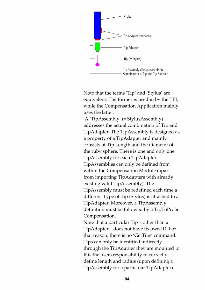
Note that the terms ‘Tip’ and ‘Stylus’ are equivalent. The former is used in by the TPI, while the Compensation Application mainly uses the latter. A ‘TipAssembly’ (= StylusAssembly) addresses the actual combination of Tip and TipAdapter. The TipAssembly is designed as a property of a TipAdapter and mainly consists of Tip Length and the diameter of the ruby sphere. There is one and only one TipAssembly for each TipAdapter. TipAssemblies can only be defined from within the Compensation Module (apart from importing TipAdapters with already existing valid TipAssembly). The TipAssembly must be redefined each time a different Type of Tip (Stylus) is attached to a TipAdapter. Moreover, a TipAssembly definition must be followed by a TipToProbe Compensation. Note that a particular Tip – other than a TipAdapter – does not have its own ID. For that reason, there is no ‘GetTips’ command. Tips can only be identified indirectly through the TipAdapter they are mounted to It is the users responsibility to correctly define length and radius (upon defining a TipAssembly for a particular TipAdapter).
84
These values (in addition to a user‐ defined comment) can be retrieved through the command GetTipAdapters.
• ES_C_GetTipAdapter Gets the ID of the currently active Tip Adapter.
• ES_C_GetTCamToTrackerCompensations Reads all T‐Cam to Tracker‐ compensations stored in the database. Apart from the internal ID and name, a series of properties is delivered.
• ES_C_GetTCamToTrackerCompensation Reads the currently active T‐Cam to Tracker compensation ID. Only the internal ID is returned. For additional information, the properties need to be looked up in the list delivered by ES_C_ GetTCamToTrackerCompensations
• ES_C_SetTCamToTrackerCompensation Sets the specified tracker compensation with the given ID as the active one. The available TCamToTracker compensations including their IDs can be retrieved with the command ʹ GetTCamToTrackerCompensation ʹ.
• ES_C_GetProbeCompensations Reads all Probe‐ compensations stored in the database. Apart from the internal ID and name, a series of properties is delivered.
• ES_C_GetProbeCompensation Reads the currently active probe compensation ID. Only the internal ID is returned. For additional information, the properties need to be looked up in the list delivered by ES_C_GetTCamToTrackerCompensations
• ES_C_SetProbeCompensation Sets the specified Probe compensation with the given ID as the active one. The available
85
Probe compensations including their IDʹs can be retrieved with the command ʹ Get GetProbeCompensations ʹ.
• ES_C_GetTipToProbeCompensations Reads all TipToProbe‐ compensations stored in the database. Apart from the internal ID and name, a series of properties is delivered. This command should no longer be used. It is only kept for compatibility reasons. Rather use ʹ ES_C_GetTipToProbeCompensations2ʹ instead (see further below).
• ES_C_GetTipToProbeCompensation Reads the currently active TipToProbe compensation ID. Only the internal ID is returned. For additional information, the properties need to be looked up in the list delivered by ES_C_GetTipToProbeCompensations
• ES_C_SetExternTriggerParams Set the behavior of the external trigger. related structure: ExternTriggerParamsT. See ʹTracker Trigger Interfaceʹ Appendix for a more detailed description of trigger‐ issues.
• ES_C_GetExternTriggerParams Set the parameters of the external trigger.
• ES_C_GetErrorEllipsoid Convenience function to calculate an error ellipsoid from a given point with Standard Deviations and Covariance. Input is in current units, current CS‐type and applied orientation / transformation settings. Output is always in RHR.
• ES_C_GetMeasurementCameraInfo Returns Measurement Camera feature information. See Tracker/T‐Cam hardware manual for details. See also GetMeasurementCameraInfoRT structure.
86
• ES_C_GetMeasurementProbeInfo Returns Probe feature information. See Tracker/Probe hardware manual for details. See also GetMeasurementProbeInfoRT structure.
• ES_C_SetLongSystemParameter This is an advanced command to set SystemSettings parameters of type Long, Boolean and enum‐ types individually. This approach was chosen to avoid extending the existing ʹSystemSettingsDataTʹ structure. There are now some parameters covered by both commands (For example WeatherMonitorStatus). For these, either command (SetSystemSettings or SetLongSystemParameter) can be used. See enum ES_SystemParameter for values supported by this command. Some system parameters are new and can only be addressed by this command and not by the former SetSystemSettings command (Example: ES_SP_AllowProbeWithoutTip).
• ES_C_GetLongSystemParameter Get current (long‐ type) system parameter. The opposite of ES_C_SetLongSystemParameter
• ES_C_GetMeasurementStatusInfo Get information about availability of all types of compensations and related hardware. The information data is delivered as a long value representing a bit‐mask. Use the enum ES_MeasurementStatusInfo values to identify / mask the long parameter information.
• ES_C_GetCurrentPrismPosition
Get the current position of the prism the laser beam is currently attached to. This can be a reflector or the prism of a probe.
87
Delivered position parameters are with all ‘filters’ applied (Units, CS‐ Type, Transformation, Orientation). In other words: the ‘same’ values as a stationary measurement would deliver. However, these position values are NOT as accurate as stationary measurements. Do NOT use these values as measurements where precise measurements are required. The background for this command is as follows: If a probe is attached, it is not possible to take 3D measurements to the probe prism. A measurement to the probe delivers the tip position, not the prism position. However, there exist situations where the position of the probe prism may be of interest (for example when issuing a GoPosition as a reaction of a beam broken event – supposed the probe is always placed to the same location). Thus, this command is probably only of interest for Probe related enterprises.
• ES_C_SetDoubleSystemParameter This command is virtually the same as ES_C_SetLongSystemParameter. The only difference is that it takes ʹdouble‐ typeʹ parameters. See ES_SystemParameter, where items suitable to this command have been marked with a D_ prefix. Example for such a parameter: ES_SP_D_ObjectTemperatureTolerance.
• ES_C_GetDoubleSystemParameter Get current (double‐ type) system parameter. The opposite of ES_C_SetDoubleSystemParameter.
• ES_C_GetObjectTemperature Get the Object Temperature. This command only succeeds if there is a weather monitor
88
(Leica AT meteo station or Thommen station) connected to emScon. A temperature device must be connected to the weather stations TEMP2 port (applies to Thommen and AT station). For the AT meteo station, TEMP1 relates to an integrated temperature sensor while for the Thommen station, it is assumed that both, TEMP1 and TEMP2 ports have a sensor assigned. TEMP1 is used for air temperature and TEMP2 serves for Object Temperature. Note (Thommen only): if TEMP1 is not used and there is only a device assigned to TEMP2, then TEMP2 is interpreted as air temperature. In this case, there is no object Temperature available and the ʹGetObjectTemperatureʹ command will fail with a usage conflict error.
• ES_C_GetTriggerBoardInfo Returns feature information about the trigger board. This is an advanced / diagnostic command. Not usually used by common applications. See Tracker/T‐Cam hardware manual for details. See GetTriggerBoardInfoRT structure. See also ʹTracker Trigger Interfaceʹ Appendix for a more detailed description of trigger‐ issues.
• ES_C_GetOverviewCameraInfo Returns feature information about the (optional) overview camera. See Tracker/T‐Cam hardware manual for details. See also GetOverviewCameraInfoRT structure.
• ES_C_ClearCommandQueue With emScon version V2.3, command buffering has been introduced. ʹServer Busyʹ errors will therefore no longer
89
apply under normal conditions. Instead, commands will be appended to a queue when sent while a previous command is still busy. The queued command(s) will be executed as soon as the previous command finishes. However, this mechanism is disabled by default (due to compatibility reasons to existing client applications). The buffering‐level must be explicitly enabled with the ʹES_SP_TcpCommandQueueSizeʹ system setting (to be used with SetLongSystemParamter). The maximum level is 10 (= max queue‐ size). Example: if queue size is set to 5 and an application is trying to buffer more than 5 commands, then a ʹServer Busyʹ is being issued. The default level is zero (command buffering disabled)
• ES_C_GetADMInfo2 Returns Absolute Distance Meter feature information (Type, Version, Serial Number, measuring range), if available (i.e. if a LTD/AT series tracker). This is an extended version of the former command ʹGetADMInfoʹ. ʹGetADMInfoʹ is only kept for compatibility reasons to existing applications. New applications should use ʹGetADMInfo2ʹ instead.
• ES_C_GetTrackerInfo Returns Tracker feature information (Version and Serial Number, tracker‐ type, measuring ranges, configuration etc). This is a new command introduced with emScon V2.3.
• ES_C_GetNivelInfo2 Returns ʹNivelʹ (Inclination sensor) feature information, if a ʹNivelʹ is available. (Type, Version, Serial Number, measuring
90
ranges..). This is an extended version of the former command ʹGetNivelInfoʹ. ʹGetNivelInfoʹ is only kept for compatibility reasons to existing applications. New applications should use ʹGetNivelInfo2ʹ instead.
• ES_C_RestoreStartupConditions Resets the system to a state as if there was a reboot of the tracker server. The effect is virtually the same as for the ʹES_C_ExitApplicationʹ command, except the server does not stop and thus the connection does not get lost. All non‐ persistent settings (such as ʹtrigger sourceʹ, ʹshow all 6DoF measurementsʹ etc.) are reset to defaults. This command is convenient during development of an application, when crashes or immediate stopping upon debugging occurs. Nevertheless, itʹs a good idea to perform this call every time at startup of an application ‐ even for retail versions. Attention: It is recommended to execute this command upon startup and only upon startup of a client‐ application (i.e. just after connecting to emScon server). This command may only be called with caution later at runtime. It may have side effects the application is not aware of.
• ES_C_GoAndMeasure The ʹGoAndMeasureʹ command is just for convenience. Its primary intention is for automated inspection tasks. ʹGoAndMeasureʹ combines the functionality of the command ʹGoPositionʹ and a stationary 3D measurement. The advantage is an improved speed, especially if a T‐Cam is mounted. (A
91
ʹtraditionalʹ Go Position ‐ if a T‐Cam is mounted ‐ takes a longer time because the system first needs to detect whether the target is a Probe or just a Reflector. The ʹGoAndMeasureʹ command ‐ since restricted to 3D ‐ can surpass this detection task). Note that ʹGoAndMeasureʹ always performs a 3D stationary measurement, regardless of the current measurement mode! However, the measurement parameters are the same as those set with ʹSetStationaryModeParamsʹ. The three input values of ʹGoAndMeasureʹ have the same meaning as those of the command ʹGoPositionʹ: They specify the location where the laser is directed to, followed by a spiral search and a measurement. The input Values are in current units / CS‐type and according to applied orientation / transformation parameters. The result (i.e. the coordinates of the measured point, if command successful), is returned the same way as for an ordinary stationary measurement: through either a ʹSingleMeasResultTʹ or a ʹSingleMeasResult2Tʹ, depending on the selected statistic level. Only in case of failure, the error code is returned through a ʹGoAndMeasureRTʹ structure. Note that the implementation of the ʹGoAndMeasureʹ command in the emScon COM interface (LTControl) is slightly different from the description here (which relates to the C‐ interface). However, the COM Type‐Library describes the functionality in a self‐ explaining manner.
• ES_C_GetTipToProbeCompensations2 Reads all TipToProbe‐ compensations
92
stored in the database. Apart from the internal ID and name, a series of properties is delivered. This command replaces the former ES_C_GetTipToProbeCompensationsʹ command.
ES_ResultStatus
Defines the supported result status values received as an answer to TPI commands.
The ES_ResultStatus enum only defines those errors that originate on the emScon server. It does not cover those errors that originate at the sensor controllers. For a complete listing of possible hardware/controller errors, see the Appendices at the end of this manual.
93
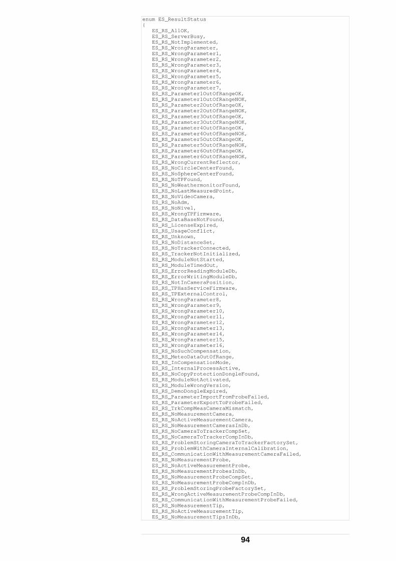
enum ES_ResultStatus { ES_RS_AllOK, ES_RS_ServerBusy, ES_RS_NotImplemented, ES_RS_WrongParameter, ES_RS_WrongParameter1, ES_RS_WrongParameter2, ES_RS_WrongParameter3, ES_RS_WrongParameter4, ES_RS_WrongParameter5, ES_RS_WrongParameter6, ES_RS_WrongParameter7, ES_RS_Parameter1OutOfRangeOK, ES_RS_Parameter1OutOfRangeNOK, ES_RS_Parameter2OutOfRangeOK, ES_RS_Parameter2OutOfRangeNOK, ES_RS_Parameter3OutOfRangeOK, ES_RS_Parameter3OutOfRangeNOK, ES_RS_Parameter4OutOfRangeOK, ES_RS_Parameter4OutOfRangeNOK, ES_RS_Parameter5OutOfRangeOK, ES_RS_Parameter5OutOfRangeNOK, ES_RS_Parameter6OutOfRangeOK, ES_RS_Parameter6OutOfRangeNOK, ES_RS_WrongCurrentReflector, ES_RS_NoCircleCenterFound, ES_RS_NoSphereCenterFound, ES_RS_NoTPFound, ES_RS_NoWeathermonitorFound, ES_RS_NoLastMeasuredPoint, ES_RS_NoVideoCamera, ES_RS_NoAdm, ES_RS_NoNivel, ES_RS_WrongTPFirmware, ES_RS_DataBaseNotFound, ES_RS_LicenseExpired, ES_RS_UsageConflict, ES_RS_Unknown, ES_RS_NoDistanceSet, ES_RS_NoTrackerConnected, ES_RS_TrackerNotInitialized, ES_RS_ModuleNotStarted, ES_RS_ModuleTimedOut, ES_RS_ErrorReadingModuleDb, ES_RS_ErrorWritingModuleDb, ES_RS_NotInCameraPosition, ES_RS_TPHasServiceFirmware, ES_RS_TPExternalControl, ES_RS_WrongParameter8, ES_RS_WrongParameter9, ES_RS_WrongParameter10, ES_RS_WrongParameter11, ES_RS_WrongParameter12, ES_RS_WrongParameter13, ES_RS_WrongParameter14, ES_RS_WrongParameter15, ES_RS_WrongParameter16, ES_RS_NoSuchCompensation, ES_RS_MeteoDataOutOfRange, ES_RS_InCompensationMode, ES_RS_InternalProcessActive, ES_RS_NoCopyProtectionDongleFound, ES_RS_ModuleNotActivated, ES_RS_ModuleWrongVersion, ES_RS_DemoDongleExpired, ES_RS_ParameterImportFromProbeFailed, ES_RS_ParameterExportToProbeFailed, ES_RS_TrkCompMeasCameraMismatch, ES_RS_NoMeasurementCamera, ES_RS_NoActiveMeasurementCamera, ES_RS_NoMeasurementCamerasInDb, ES_RS_NoCameraToTrackerCompSet, ES_RS_NoCameraToTrackerCompInDb, ES_RS_ProblemStoringCameraToTrackerFactorySet, ES_RS_ProblemWithCameraInternalCalibration, ES_RS_CommunicationWithMeasurementCameraFailed, ES_RS_NoMeasurementProbe, ES_RS_NoActiveMeasurementProbe, ES_RS_NoMeasurementProbesInDb, ES_RS_NoMeasurementProbeCompSet, ES_RS_NoMeasurementProbeCompInDb, ES_RS_ProblemStoringProbeFactorySet, ES_RS_WrongActiveMeasurementProbeCompInDb, ES_RS_CommunicationWithMeasurementProbeFailed, ES_RS_NoMeasurementTip, ES_RS_NoActiveMeasurementTip, ES_RS_NoMeasurementTipsInDb,
94
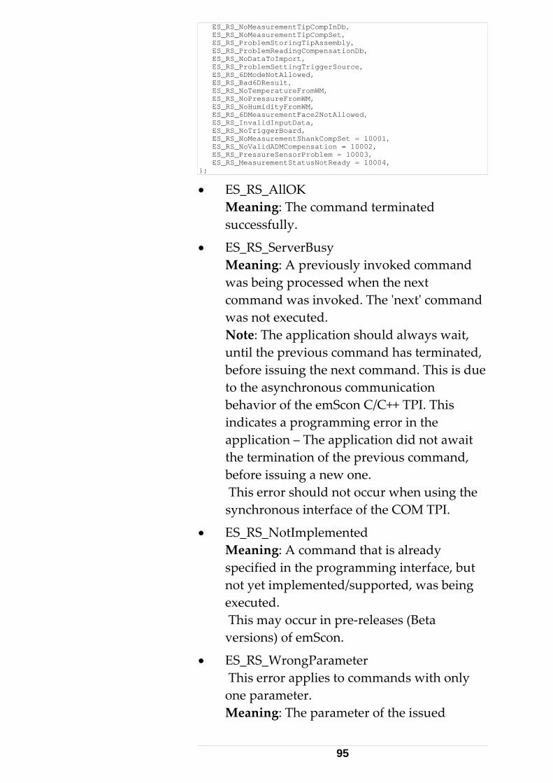
ES_RS_NoMeasurementTipCompInDb, ES_RS_NoMeasurementTipCompSet, ES_RS_ProblemStoringTipAssembly, ES_RS_ProblemReadingCompensationDb, ES_RS_NoDataToImport, ES_RS_ProblemSettingTriggerSource, ES_RS_6DModeNotAllowed, ES_RS_Bad6DResult, ES_RS_NoTemperatureFromWM, ES_RS_NoPressureFromWM, ES_RS_NoHumidityFromWM, ES_RS_6DMeasurementFace2NotAllowed, ES_RS_InvalidInputData, ES_RS_NoTriggerBoard, ES_RS_NoMeasurementShankCompSet = 10001, ES_RS_NoValidADMCompensation = 10002, ES_RS_PressureSensorProblem = 10003, ES_RS_MeasurementStatusNotReady = 10004, };
• ES_RS_AllOK Meaning: The command terminated successfully.
• ES_RS_ServerBusy Meaning: A previously invoked command was being processed when the next command was invoked. The ʹnextʹ command was not executed. Note: The application should always wait, until the previous command has terminated, before issuing the next command. This is due to the asynchronous communication behavior of the emScon C/C++ TPI. This indicates a programming error in the application – The application did not await the termination of the previous command, before issuing a new one. This error should not occur when using the synchronous interface of the COM TPI.
• ES_RS_NotImplemented Meaning: A command that is already specified in the programming interface, but not yet implemented/supported, was being executed. This may occur in pre‐releases (Beta versions) of emScon.
• ES_RS_WrongParameter This error applies to commands with only one parameter. Meaning: The parameter of the issued
95
command was not accepted and executed. This error is issued if, for example:
‐ A positive value is expected but the user passed a negative one.
‐ The parameter is out of valid range. Very often, this is due to wrong unit selection.
Note: Check the valid range and current unit of the command parameter (see command description). Example: The system is currently set to ʹMetersʹ for length units, but the user enters 5000 (5000 mm) instead of 5.
• ES_RS_WrongParameter1
• ES_RS_WrongParameter2
• ES_RS_WrongParameter3
• ES_RS_WrongParameter4
• ES_RS_WrongParameter5
• ES_RS_WrongParameter6
• ES_RS_WrongParameter7
• ES_RS_WrongParameter8
• ES_RS_WrongParameter9
• ES_RS_WrongParameter10
• ES_RS_WrongParameter11
• ES_RS_WrongParameter12
• ES_RS_WrongParameter13
• ES_RS_WrongParameter14
• ES_RS_WrongParameter15
• ES_RS_WrongParameter16 Meaning: Applies to commands with more than one parameter. The symbol specifies which one of the parameters is wrong.
• ES_RS_Parameter1OutOfRangeOK
• ES_RS_Parameter1OutOfRangeNOK
96
• ES_RS_Parameter2OutOfRangeOK
• ES_RS_Parameter2OutOfRangeNOK
• ES_RS_Parameter3OutOfRangeOK
• ES_RS_Parameter3OutOfRangeNOK
• ES_RS_Parameter4OutOfRangeOK
• ES_RS_Parameter4OutOfRangeNOK
• ES_RS_Parameter5OutOfRangeOK
• ES_RS_Parameter5OutOfRangeNOK
• ES_RS_Parameter6OutOfRangeOK
• ES_RS_Parameter6OutOfRangeNOK Meaning: OutOfRangeOK (warning) – The value of the specified parameter was out of the recommended range (but within the valid range) and accepted. The command was executed. OutOfRangeNOK (error) – The value of the specified parameter was not within the valid range and was not accepted. The command was not executed. These errors/warnings typically apply to atmospheric values such as temperature and pressure. The system can still perform the requested action, but the result will not be within specifications. In case of OutOfRangeOK, the user should be aware that the system might not deliver highest accuracy.
• ES_RS_WrongCurrentReflector Meaning: An invalid reflector was set (e.g. if the parameter of command SetReflector applies to a non‐existing reflector ID or to an ID of an existing but inaccurate reflector. Note: This is usually a programming error in the application. The application should not allow the user to set an invalid reflector. The application should query the IDs of valid
97
reflectors with the command GetReflectors and then offer these as possible parameters for the SetReflector command.
• ES_RS_NoCircleCenterFound Meaning: This error occurs only in the continuous measurement mode, CircleCenterMode. The calculation of the circle center failed. Note: The measurements represent either a very small sector of the circle and/or describe a circle not within the required accuracy, which is not sufficient for calculation. The Circle Center Mode parameters may not have been set properly. See command ʹSetCircleCenterModeParamsʹ.
• ES_RS_NoSphereCenterFound Meaning: Similar to ES_RS_NoCircleCenterFound. Note: The measurements represent a very small sector of the sphere. For good results, at least half of the sphere should be covered by measurements. The Sphere Center Mode parameters may not have been set properly See command ʹSetSphereCenterModeParamsʹ.
• ES_RS_NoTPFound Meaning: There is no communication between the tracker controller and the tracker server. Either the connection is broken or the tracker controller did not boot and connect properly. Often this error occurs if the application tries to access the tracker server before the boot process is finished or if the boot process failed for some reason. For emScon version 1.5 and higher, it is recommended to await the ES_SSC_ServerStarted event before trying to issue a command.
98
Note: This problem can occur with use of an External Tracker Server (cable unplugged/damaged, plugged to wrong connector). This problem is minimized for LT Controller plus/base since both the tracker server and controller are integrated in one unit.
• ES_RS_NoWeathermonitorFound Meaning: A command or polling mechanism could not access an external weather station. The weather station is not present/connected/switched on. Note: If there is a weather station connected, check the cable and make sure the power is switched on. If no weather station is connected, set the SystemStatusFlag HasWeatherMonitor to zero. (Command SetSystemStatus). The flag must be ≠ 0, in order to access the weather station.
• ES_RS_NoLastMeasuredPoint Meaning: This error occurs after a command GoLastMeasuredPoint, when no stationary point has been measured since last system boot. There is no last measured point to go to. Note: Ensure that the user or the application does not call GoLastMeasuredPoint, if no stationary point has been measured since last system boot.
• ES_RS_NoVideoCamera Meaning: A command could not access the Overview Camera. This error can only occur if no Overview Camera is attached to the system. Note: If no camera is connected, set the SystemStatusFlag HasVideoCamera to zero. (Command SetSystemStatus). The application should not call camera related commands, if there is no camera attached.
99
There exist different types of overview cameras that differ in internal parameters (focus distance, CCD chip size). Older emScon versions were not able to detect whether an overview camera was mounted or not, not to speak of type recognition (indeed it was the overview camera hardware that did not support type recognition). For that reason, the flag ʹHasVideoCameraʹ was originally introduced. Thus, the user had to ʹtellʹ the system when an overview camera was mounted. Newer EmScon versions (2.0 and up) are able to detect the camera type automatically. Hence, this flag theoretically has become obsolete. However, currently the camera type is recognized only when the ʹhHasVideoCameraʹ flag is enabled. If your system is equipped with an overview camera, it is highly recommended to always having this flag checked (default is unchecked). Otherwise, the system may not detect the correct camera type and use wrong (default) parameters. However, wrong parameters do not cause any fatal failures. The only effect will be that the ʹFind Reflectorʹ feature by clicking to the live video image by mouse pointer will move the tracker inaccurately (typically, the tracker will move double or half the amount of the ʹclickedʹ distance).
• ES_RS_NoAdm Meaning: A command could not access the absolute distance meter of the tracker. This error should only occur if a tracker is not equipped with an ADM (i.e. LT/AT‐ series only). Note: If this error occurs for LTD/AT trackers, this probably indicates a hardware failure.(Refer to Leica service).
100

• ES_RS_NoNivel Meaning: A command could not access the external Leica ʹNivelʹ inclination sensor. Either it is not present or not correctly connected. Note: If there is a ʹNivelʹ connected, check the cable. If no ʹNivelʹ is present, set the SystemStatusFlag HasNivel to zero (Command SetSystemStatus). The flag must be ≠ 0, in order to access the ʹNivelʹ.
• ES_RS_WrongTPFirmware Meaning: The installed Firmware on the Tracker controller does not match the actual hardware. Note: Upgrade the firmware (Refer to Leica service)
• ES_RS_DataBaseNotFound Meaning: No database could be found on the tracker server. Note: There are no compensation parameters found for the attached sensor. Send the respective parameter files to the emScon server using the transfer tool.
• ES_RS_LicenseExpired Meaning: The Copy‐ Protection Dongle has expired (Probably due to a demo dongle?). Note: Request for a dongle Field‐ upgrade at Leica or get a new dongle.
• ES_RS_UsageConflict Meaning: Some system modes disable other commands, because they do not make sense in this context. For example, if the system is equipped with a weather station and is set up to automatically monitor the temperature, pressure and humidity, the system will prevent a manual setting of these values. The command SetEnvironmentParams will issue an error ES_RS_UsageConflict. The command GetEnvironmentParams will
101
work and deliver the actual values measured by the monitor. If the weather station mode is set to ʹread and recalculate Refractionʹ, then the same applies to the command SetRefractionParams. It will issue a ES_RS_UsageConflict, since setting the refraction index manually would conflict the automatic mechanism and would be overwritten upon the next weather station read cycle (~ 20 seconds). Note: The application should not call SetEnvironmentParams and/or SetRefractionParams, if these values are automatically updated by the weather station, as per system settings.
• ES_RS_Unknown Meaning: An unknown error occurred. Should never occur as a response to a command.
• ES_RS_NoDistanceSet Meaning: The interferometer has no valid reference distance. Measuring is not possible in this condition. Note: Trackers with ADM may attach to a stable reflector anywhere. Use GoPosition or, if close to a reflector, FindReflector. If ʹKeep last position is enabledʹ, the system tries to re‐establish the distance automatically as soon as a reflector can be tracked. For trackers without a ADM:
‐ Place the reflector in the Birdbath. Do a GoBirdbath.
‐ Move reflector to the measuring position without interrupting the beam.
• ES_RS_NoTrackerConnected Meaning: The connection between controller and tracker is broken. Note: Check all cables between controller and tracker.
102
• ES_RS_TrackerNotInitialized Meaning: The tracker is not initialized. Note: Execute the Initialize command. Set the environmental parameters (manually/weather station) before initialization. See also chapter ʹInitial Stepsʹ
• ES_RS_ModuleNotStarted
• ES_RS_ModuleTimedOut
• ES_RS_ErrorReadingModuleDb
• ES_RS_ErrorWritingModuleDb Meaning: These errors indicate a software installation problem on the emScon server. Note: Reinstall emScon software.
• ES_RS_NotInCameraPosition Meaning: Application tried to grab a video image from the Overview Camera, when the tracker was not in camera position. Note: Issue an ActivateCameraView command first.
• ES_RS_TPHasServiceFirmware Meaning: The server has loaded service firmware. This firmware is not suitable for ordinary tracker usage. This error cannot occur under normal conditions. Note: Refer to Leica service.
• ES_RS_TPExternalControl Meaning: The controller is running under external (e.g. AXYZ) control. Note: Reboot the tracker processor.
• ES_RS_NoSuchCompensation Meaning: The ID of a non‐existent Compensation was passed to the SetCompensation command. Note: Use the GetCompensations command to get a list of valid Compensations.
103
• ES_RS_MeteoDataOutOfRange Meaning: The current environmental parameters (Temperature, Pressure, Humidity) are out of range. Note: Use SetEnvironmtalParams command to set these parameters correctly. If a weather station is attached, check for proper functioning. A Meteo station (Leica AT station or Thommen station) must be connected to the tracker system and switched‐on before booting emScon. Incorrect environmental data may be produced, if the weather station is connected/switched‐on later than that. For the Thommen station, connecting the combined Temperature/Pressure device is optional. However, if missing, the other (small) Temperature device must be present (applies to Thommen only ‐ the AT station contains an integrated air temperature sensor). If no humidity device is available, a default value of 70% is assumed (Thommen only ‐ AT station contains an integrated humidity sensor). Note: Other than for temperature and pressure, the influence of the humidity to the refraction index is marginal. See also ES_RS_NoTemperatureFromWM, ES_RS_NoPressureFromWM, and ES_RS_NoHumidityFromWM.
• ES_RS_InCompensationMode Meaning: The server is set to Compensation Mode. This is the case when the Compensation Application is active. During this state, all TPI commands are locked. Note: Quit the Compensation Application (Web App). Remark: In rare situations ‐ for example after a crash of the Compensation Application ‐ it may happen that the system remains in
104
compensation mode and the server can neither be accessed by the TPI nor by the Web Application. In this case, the tracker server needs to be rebooted. For further details see remark at chapter ʹApplication Initial Stepsʹ / ʹEssential Stepsʹ.
• ES_RS_InternalProcessActive Meaning: The server is still busy with a command. Note: The application must wait until the previous command has finished, before issuing a new command (asynchronous behavior).
• ES_RS_NoCopyProtectionDongleFound Meaning: The copy protection dongle is missing. Note: Make sure the dongle is connected at the correct port.
• ES_RS_ModuleNotActivated Meaning: The copy protection dongle does not qualify to use the specified module. Note: Refer to Leica representative to get a dongle field‐ upgrade.
• ES_RS_ModuleWrongVersion Meaning: The copy protection dongle does not qualify to use the specified module version. Note: Refer to Leica representative to get a dongle field‐ upgrade.
• ES_RS_DemoDongleExpired Meaning: The dongle is not activated or has expired. Note: Refer to a Leica representative. A field upgrade might be provided.
• ES_RS_ParameterImportFromProbeFailed Meaning: Importing of a probe compensation failed. Note: Make sure Probe has information in its
105
memory. Also check for potential version conflict.
• ES_RS_ParameterExportToProbeFailed Meaning: Exporting of a probe compensation failed. Note: Check for potential version conflict.
• ES_RS_TrkCompMeasCameraMismatch Meaning: The selected Tracker Compensation was not made with a T‐Cam mounted. This compensation must not be used with a Tracker wit T‐Cam mounted. Note: Select a different compensation.
• ES_RS_NoMeasurementCamera Meaning: No T‐Cam is available. Note: Mount the T‐Cam.
• ES_RS_NoActiveMeasurementCamera Meaning: The mounted T‐Cam does not match the one stored in the database. Note: Make sure mounted T‐Cam matches the camera information stored in the database.
• ES_RS_NoMeasurementCamerasInDb Meaning: No T‐Cam is defined in database. Note: Provide camera information in database.
• ES_RS_NoCameraToTrackerCompSet Meaning: No T‐Cam to tracker compensation is activated. Note: use the ʹSetTCamToTrackerCompensationʹ command to activate a compensation.
• ES_RS_NoCameraToTrackerCompInDb Meaning: No T‐Cam to Tracker compensation is available in database. Note: Perform a T‐Cam to Tracker compensation.
• ES_RS_WrongActiveCameraToTracker CompInDb
106
Meaning: T‐Cam to Tracker compensation does not match the mounted camera. Note: Use the correct camera, or provide a compensation.
• ES_RS_NoMeasurementProbe Meaning: No probe can be ʹseenʹ by the camera. Note: Move the probe to the cameraʹs viewing space.
• ES_RS_NoActiveMeasurementProbe Meaning: The detected probe cannot be set as active. Note: Make sure probe communication is OK (cable problem?)
• ES_RS_NoMeasurementProbesInDb Meaning: No Probes are available in database. Note: Import probe information.
• ES_RS_NoMeasurementProbeCompSet Meaning: No probe compensation is activated. Note: use the ʹSetProbeCompensationʹ command to activate a compensation.
• ES_RS_NoMeasurementProbeCompInDb Meaning: No probe compensation can be found in database. Note: Import or provide a probe compensation.
• ES_RS_WrongActiveMeasurementProbe CompInDb Meaning: The probe seen by the camera does not match the information in database. Note: Replace the probe by the matching one, or provide database information suitable to active probe.
• ES_RS_CommunicationWithMeasurement ProbeFailed Meaning: Possibly a hardware failure. The
107
probe should be detected automatically. Note: Relocate the probe to try again. Try with a cable connection if using a cordless probe. Refer to Leica service if problem still remains.
• ES_RS_NoMeasurementTip Meaning: No Tip is mounted at the probe. Note: Mount a tip.
• ES_RS_NoActiveMeasurementTip Meaning: The detected Tip cannot be set as active. Note: Make sure probe communication is OK (cable problem?)
• ES_RS_NoMeasurementTipsInDb Meaning: No Tips can be found in database. Note: Provide tip definition.
• ES_RS_NoMeasurementTipCompInDb Meaning: No Tip compensation can be found in database. Note: Import or provide a tip compensation.
• ES_RS_ProblemReadingCompensationDb Meaning: Compensations could not be read from database. Note: Access to the database has failed. This error should not occur under normal conditions.
• ES_RS_ProblemSettingTriggerSource Meaning: Trigger source parameters could not be set. Note: Probably a hardware problem, or no trigger board available with current system.
• ES_RS_NoMeasurementTipCompSet Meaning: Tip compensation missing. Note: A Tip / Tip Assembly must be compensated and activated before it can be used for measuring.
• ES_RS_ProblemStoringCameraToTracker FactorySet
108
Meaning: The factory parameters of the current camera could not be replicated in the database. Note: This error should not occur under normal conditions.
• ES_RS_ProblemWithCameraInternal Calibration Meaning: There is something wrong with the internal camera calibration. Note: This error should not occur under normal conditions. The camera probably needs to be repaired.
• ES_RS_CommunicationWithMeasurement CameraFailed Meaning: Possibly a hardware failure. The mounted camera should be detected automatically. Note: Remove the Camera and mount again. If still a problem, refer to Leica service.
• ES_RS_ProblemStoringProbeFactorySet Meaning: The Factory parameters of the current probe could not be stored in the database. Note: This error should not occur under normal conditions.
• ES_RS_NoDataToImport Meaning: Import Data failed since no data to import was found.
• ES_RS_ProblemStoringTipAssembly Meaning: Tip assembly could not be stored. Note: This error should not occur under normal conditions.
• ES_RS_6DModeNotAllowed Meaning: Trying to execute a 6DoF related command with a 3D measuring system, or system is set to 3D Mode. Note: Make sure the system supports 6DoF (i.e. has a camera mounted) and that one of
109
the Probe (6DoF) measurement modes is selected.
• ES_RS_Bad6DResult Meaning: The 6D coordinates delivered with this packet are not complete or even wrong (maybe zero). This situation can occur because of a bad rotation status or because not enough LED’s were visible during a ‘long time’. In other words: the system was not able to measure as many single measurements as specified during the specified measurement‐time. An application must treat such a result as an error.
• ES_RS_NoHumidityFromWM Meaning: No humidity value could be queried from the weather monitor. If a Thommen station, there is probably no (external) humidity sensor connected to the weather station. This is a legal condition. A default value of 70% is assumed in this case (Note: The influence of the Humidity to the refraction index is marginal). The Leica AT meteo station contains a humidity sensor as an integral part. It should always succeed to deliver a humidity value. NoHumidityFromWM would probably mean defective meteo hardware.
• ES_RS_NoTemperatureFromWM Meaning: No temperature value could be queried from the Weather monitor. None of the two Temperature devices is probably connected to the Thommen Weather Station. This is a fatal error since the Temperature is required for the calculation of the refraction index. At least one of the Temperature devices must be attached to the Thommen Weather monitor. If both are connected, the temperature of the combined Temperature/Humidity device has priority.
110
The Leica AT meteo station contains a TEMP1 sensor as an integral part. It should always succeed to deliver an (air‐) temperature value. NoTemperatureFromWM for an AT station would probably mean defective hardware.
• ES_RS_NoPressureFromWM Meaning: No pressure value could be queried from the Weather monitor. Since the pressure device is an integral, non‐removable part of both, Thommen and AT meteo station, this error probably indicates defective hardware. This is a fatal error since the Pressure is required for the calculation of the refraction index.
• ES_RS_6DMeasurementFace2NotAllowed Meaning: The system is in Face II while trying to do a 6D measurement. The system does not allow performing 6D measurements while in Face II. Change to Face I first.
• ES_RS_NoTriggerBoard Meaning: A trigger‐ board specific command was executed, although the system is not equipped with a trigger board. See ʹTracker Trigger Interfaceʹ Appendix for a more detailed description of trigger‐ issues.
• ES_RS_InvalidInputData Meaning: At least one of the input‐ parameters of the executed command is not valid. This error mostly applies if a coordinate triple is given in the wrong CS‐ type (for example if X,Y,Z passed where H,V,D expected). This error is similar to ʹES_RS_WrongParameter...ʹ, but less specific (since neither known which parameter, nor whether only one is wrong or several)
111
• ES_RS_NoMeasurementShankCompSet Meaning: If we are in ʹShankʹ mode, measurements without shank compensation are not allowed
• ES_RS_NoValidADMCompensation Meaning: The issued command is not available without having a valid ADM compensation; import or perform a mechanical tracker compensation
• ES_RS_PressureSensorProblem Meaning: The meteo station reported a discrepancy in terms of a too big difference from the 2 internal sensors. This only applies to new AT meteo station‐ types.
• ES_RS_MeasurementStatusNotReady Meaning: Tried to trigger a measurement while measurement status was not (yet) ready.
Remark: Error Range 100..9999 is reserved for Controller/Sensor Firmware errors (as listed in Appendices C and D), hence the gap between error #99 and #10001. ES_MeasMode
This enumeration type names the currently implemented measurement modes. Used as a parameter for the ES_C_SetMeasurementMode command. enum ES_MeasMode { ES_MM_Stationary, ES_MM_ContinuousTime, ES_MM_ContinuousDistance, ES_MM_Grid, ES_MM_SphereCenter, ES_MM_CircleCenter, ES_MM_6DStationary, ES_MM_6DContinuousTime, ES_MM_6DContinuousDistance, ES_MM_6DGrid, ES_MM_6DSphereCenter, ES_MM_6DCircleCenter, };
• ES_MM_Stationary Stationary measurement mode. Also known as ʹSingle Pointʹ measurement, where the
112
target is stationary. A stationary measurement is an average value of many tracker measurements. The parameters for a stationary measurement, number of measurements and the time span can be controlled with the ES_C_SetStationaryModeParams command.
• ES_MM_ContinuousTime Continuous measurement mode with a time interval. a measurement is triggered after the time interval. The behavior of a continuous measurement can be controlled with the ES_C_SetContinuousTimeModeParams command.
• ES_MM_ContinuousDistance Continuous Measurement mode with a distance interval. A measurement is triggered after the distance interval. The behavior of a Continuous Distance measurement can be controlled with the ES_C_SetContinuousDistanceModeParams command.
• ES_MM_Grid Continuous Measurement Mode by grid interval. A measurement is triggered after the grid interval. The behavior of a grid measurement can be controlled with the ES_C_SetGridModeParams command.
• ES_MM_SphereCenter Measurement mode to indirectly measure a sphere center point. This is achieved by a continuous measurement scan over the sphere surface. The behavior for a Sphere Center measurement can be controlled with the ES_C_SetSphereCenterModeParams command.
• ES_MM_CircleCenter Circle measurement similar to
113
ES_MM_SphereCenter. The behavior for a Circle Center measurement can be controlled with the ES_C_SetCircleCenterModeParams command.
• ES_MM_6DStationary
The Probe (6DoF) relative of ES_MM_Stationary mode. See description there.
• ES_MM_6DContinuousTime The Probe (6DoF) relative of ES_MM_ContinuousTime mode. See description there.
• ES_MM_6DContinuousDistance The Probe (6DoF) relative of ES_MM_ContinuousDistance mode. See description there.
• ES_MM_6DGrid The Probe (6DoF) relative of ES_MM_ Grid mode. See description there.
• ES_MM_6DSphereCenter The Probe (6DoF) relative of ES_MM_SphereCenter mode. See description there.
• ES_MM_6DCircleCenter The Probe (6DoF) relative of ES_MM_CircleCenter mode. See description there.
ES_MeasurementStatus
Additional status information to be delivered with each single measurement of a continuous measurement stream. Measurements with a status other than ES_MS_AllOK should be treated with care.
114
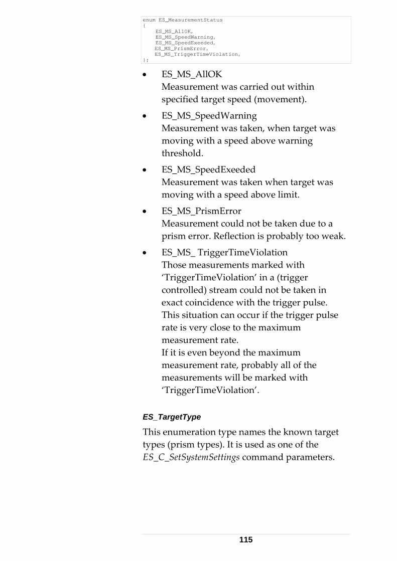
enum ES_MeasurementStatus { ES_MS_AllOK, ES_MS_SpeedWarning, ES_MS_SpeedExeeded, ES_MS_PrismError, ES_MS_TriggerTimeViolation, };
• ES_MS_AllOK Measurement was carried out within specified target speed (movement).
• ES_MS_SpeedWarning Measurement was taken, when target was moving with a speed above warning threshold.
• ES_MS_SpeedExeeded Measurement was taken when target was moving with a speed above limit.
• ES_MS_PrismError Measurement could not be taken due to a prism error. Reflection is probably too weak.
• ES_MS_ TriggerTimeViolation Those measurements marked with ‘TriggerTimeViolation’ in a (trigger controlled) stream could not be taken in exact coincidence with the trigger pulse. This situation can occur if the trigger pulse rate is very close to the maximum measurement rate. If it is even beyond the maximum measurement rate, probably all of the measurements will be marked with ‘TriggerTimeViolation’.
ES_TargetType
This enumeration type names the known target types (prism types). It is used as one of the ES_C_SetSystemSettings command parameters.
115
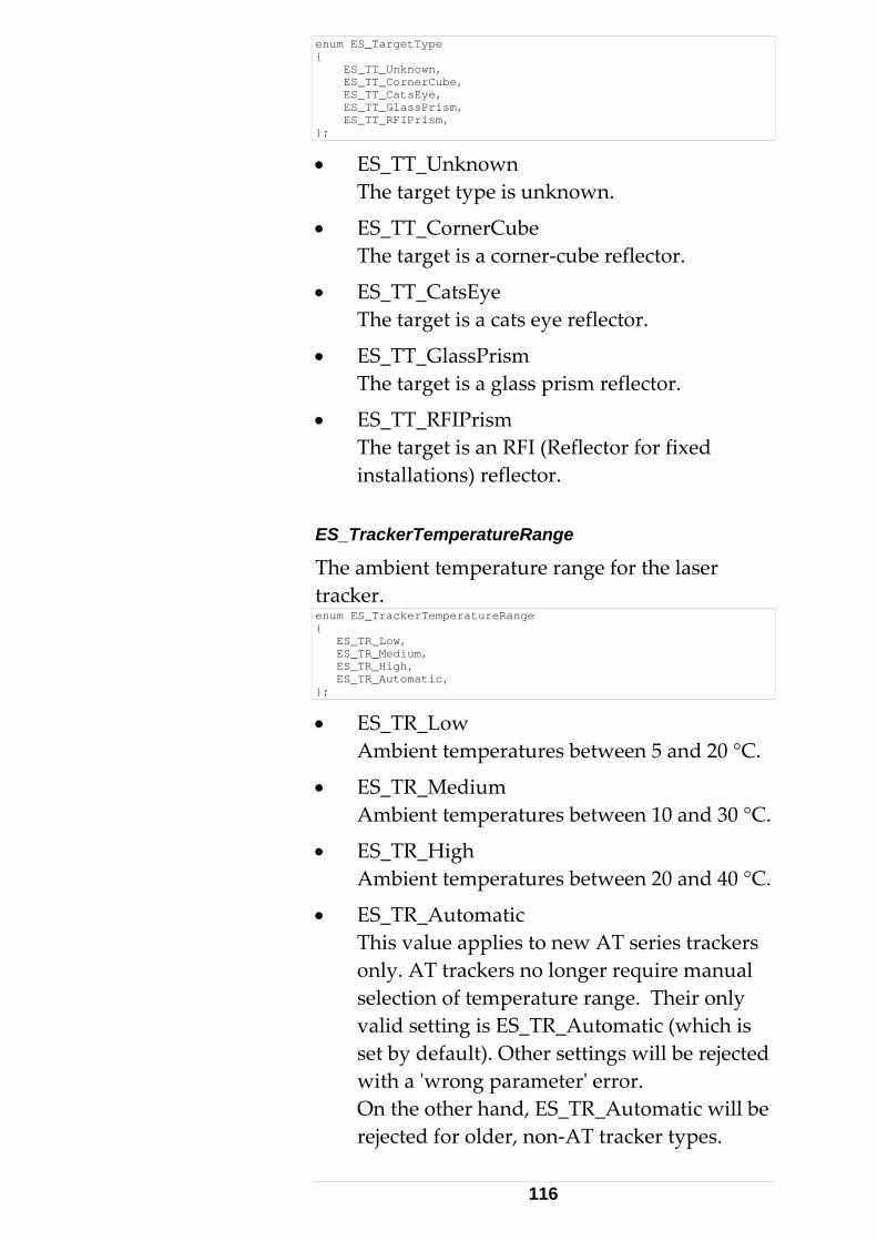
enum ES_TargetType { ES_TT_Unknown, ES_TT_CornerCube, ES_TT_CatsEye, ES_TT_GlassPrism, ES_TT_RFIPrism, };
• ES_TT_Unknown The target type is unknown.
• ES_TT_CornerCube The target is a corner‐cube reflector.
• ES_TT_CatsEye The target is a cats eye reflector.
• ES_TT_GlassPrism The target is a glass prism reflector.
• ES_TT_RFIPrism The target is an RFI (Reflector for fixed installations) reflector.
ES_TrackerTemperatureRange
The ambient temperature range for the laser tracker. enum ES_TrackerTemperatureRange { ES_TR_Low, ES_TR_Medium, ES_TR_High, ES_TR_Automatic, };
• ES_TR_Low Ambient temperatures between 5 and 20 °C.
• ES_TR_Medium Ambient temperatures between 10 and 30 °C.
• ES_TR_High Ambient temperatures between 20 and 40 °C.
• ES_TR_Automatic This value applies to new AT series trackers only. AT trackers no longer require manual selection of temperature range. Their only valid setting is ES_TR_Automatic (which is set by default). Other settings will be rejected with a ʹwrong parameterʹ error. On the other hand, ES_TR_Automatic will be rejected for older, non‐AT tracker types.
116
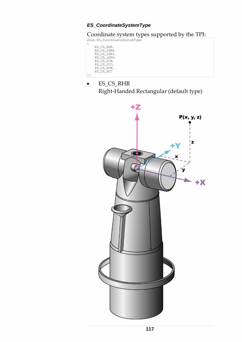
ES_CoordinateSystemType
Coordinate system types supported by the TPI: enum ES_CoordinateSystemType { ES_CS_RHR, ES_CS_LHRX, ES_CS_LHRY, ES_CS_LHRZ, ES_CS_CCW, ES_CS_CCC, ES_CS_SCW, ES_CS_SCC };
• ES_CS_RHR Right‐Handed Rectangular (default type)
117
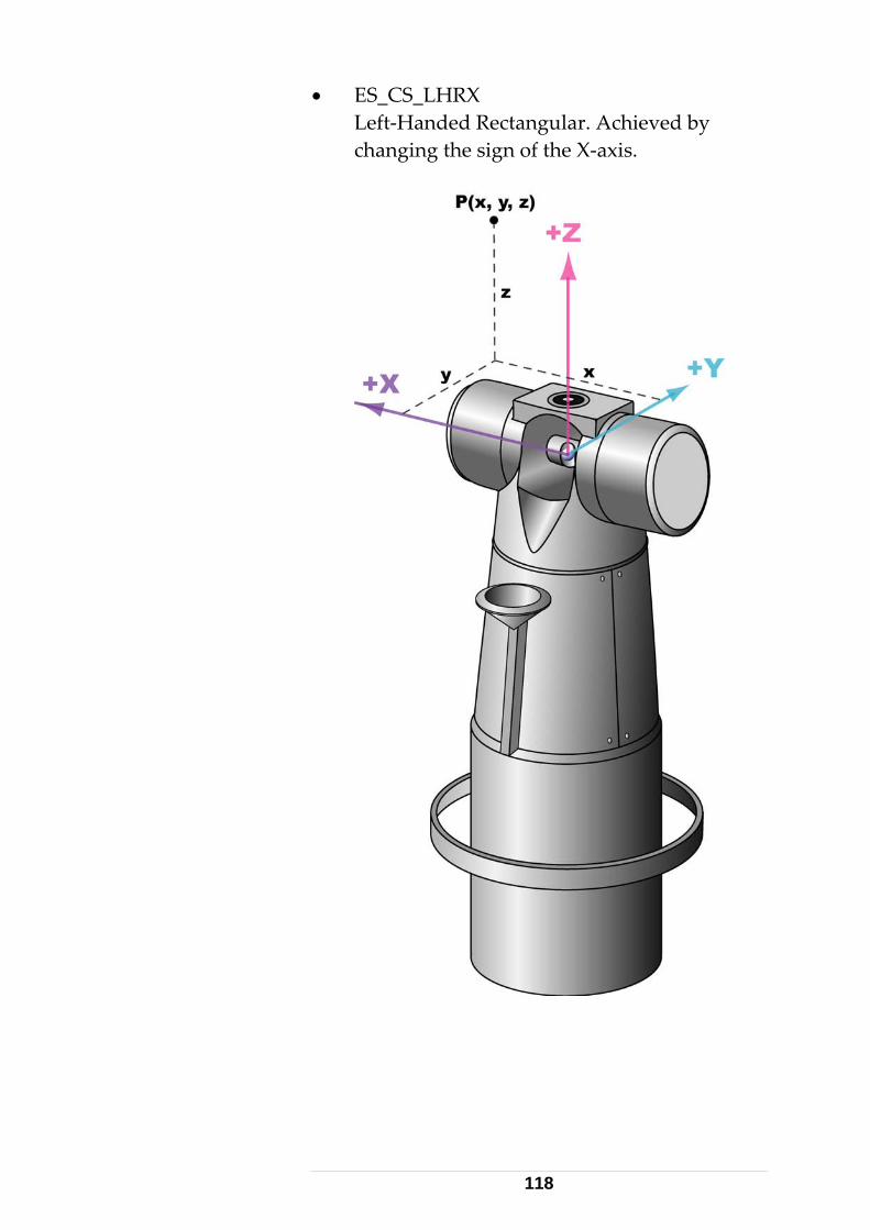
• ES_CS_LHRX Left‐Handed Rectangular. Achieved by changing the sign of the X‐axis.
118
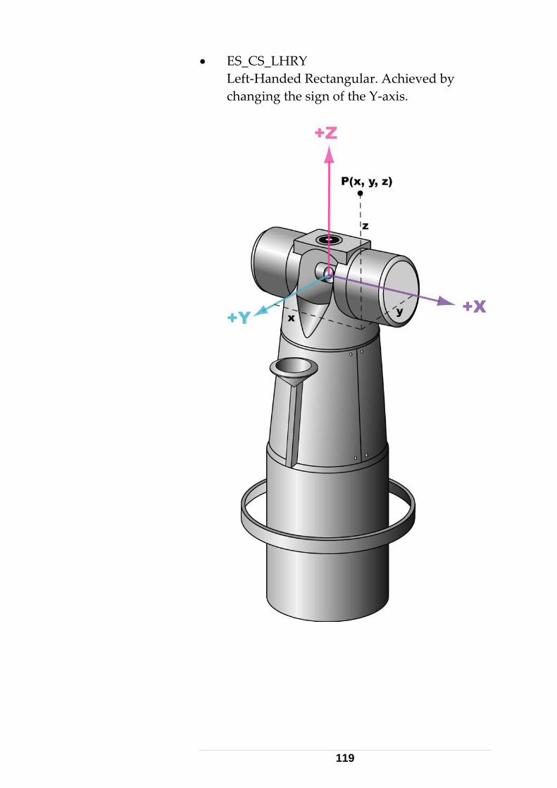
• ES_CS_LHRY Left‐Handed Rectangular. Achieved by changing the sign of the Y‐axis.
119
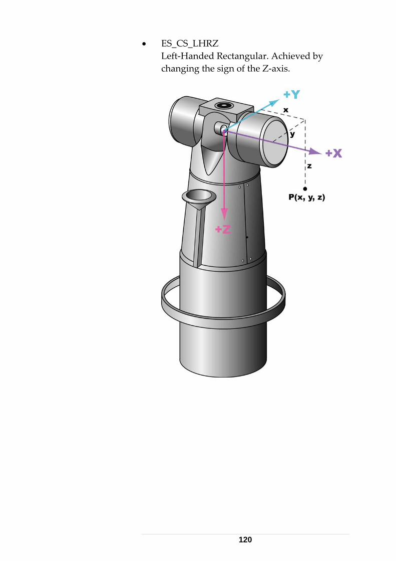
• ES_CS_LHRZ Left‐Handed Rectangular. Achieved by changing the sign of the Z‐axis.
120
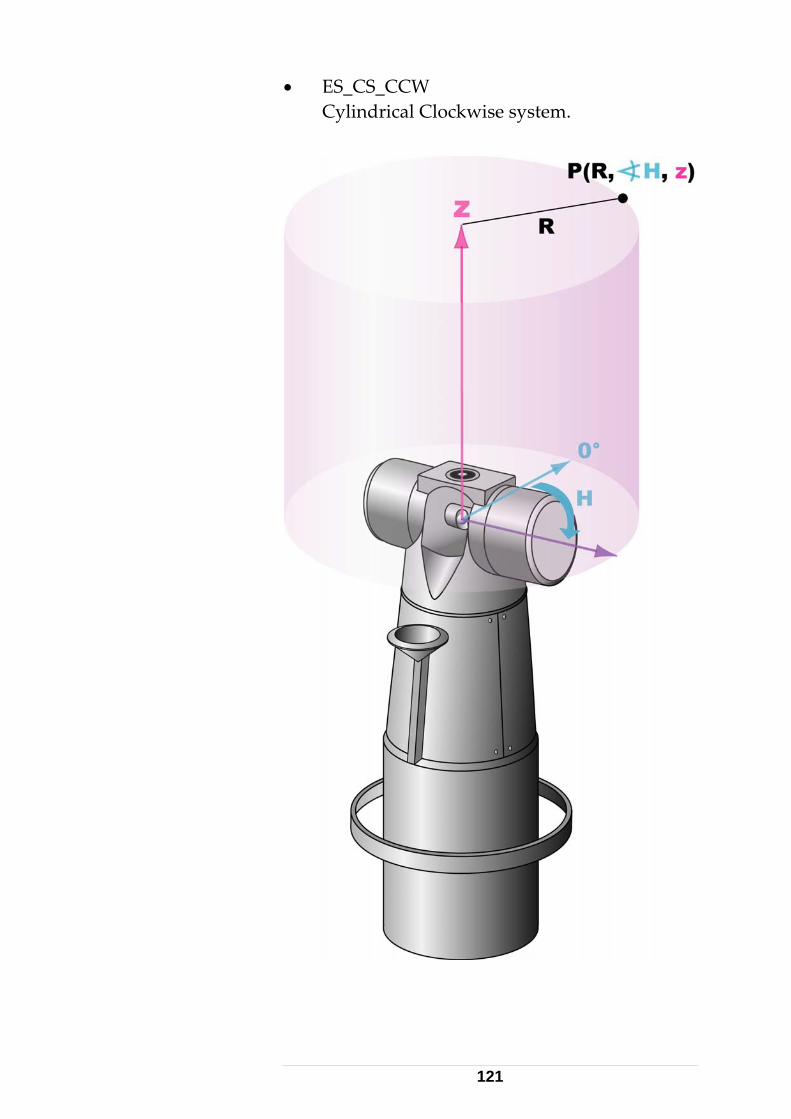
• ES_CS_CCW Cylindrical Clockwise system.
121
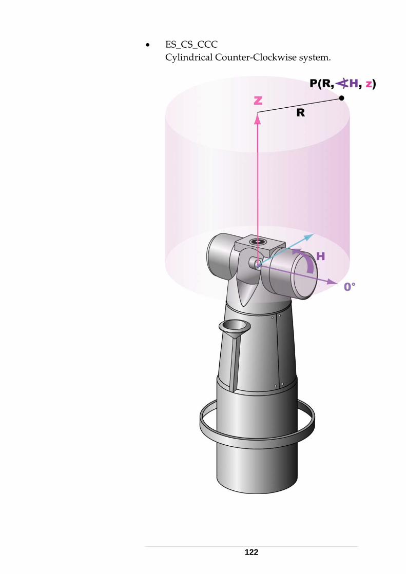
• ES_CS_CCC Cylindrical Counter‐Clockwise system.
122
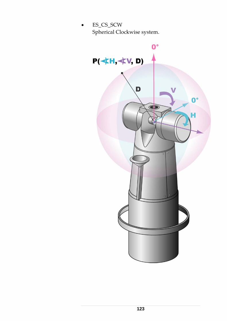
• ES_CS_SCW Spherical Clockwise system.
123
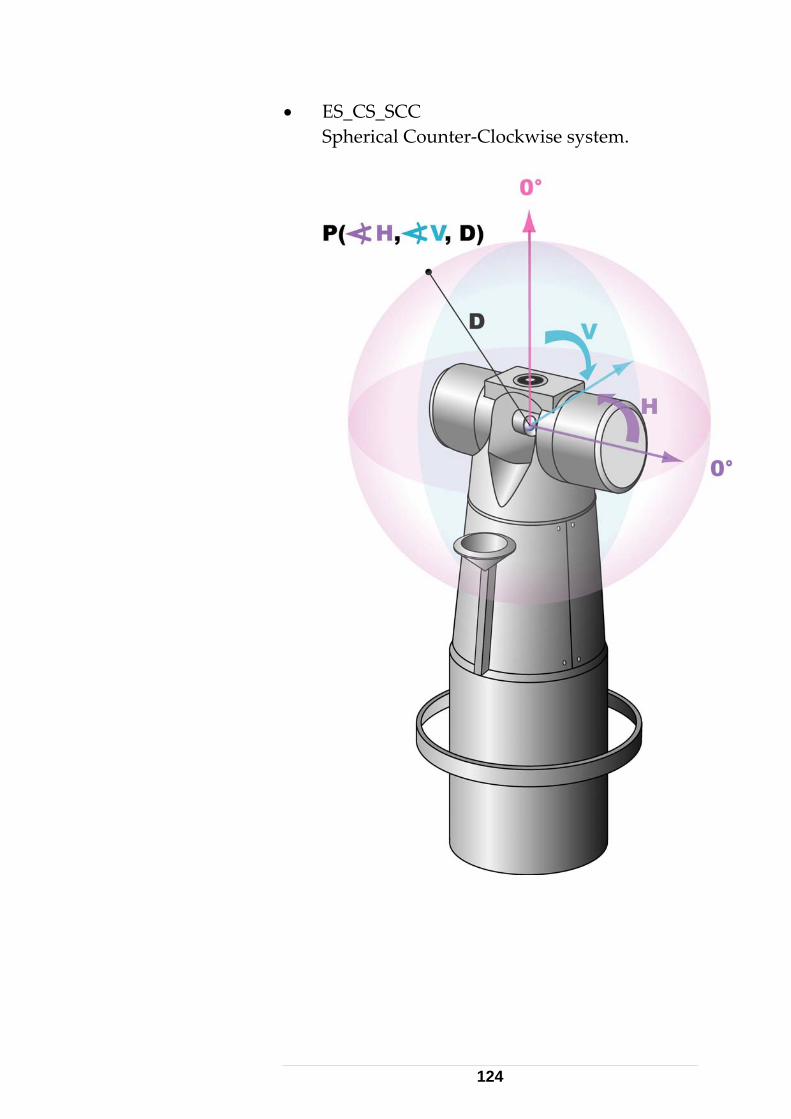
• ES_CS_SCC Spherical Counter‐Clockwise system.
124
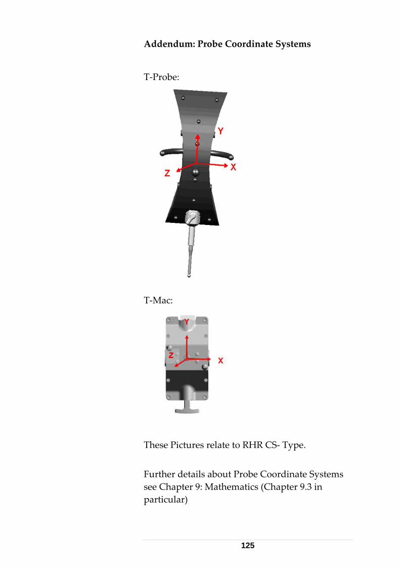
Addendum: Probe Coordinate Systems
T‐Probe:
T‐Mac:
These Pictures relate to RHR CS‐ Type.
Further details about Probe Coordinate Systems see Chapter 9: Mathematics (Chapter 9.3 in particular)
125
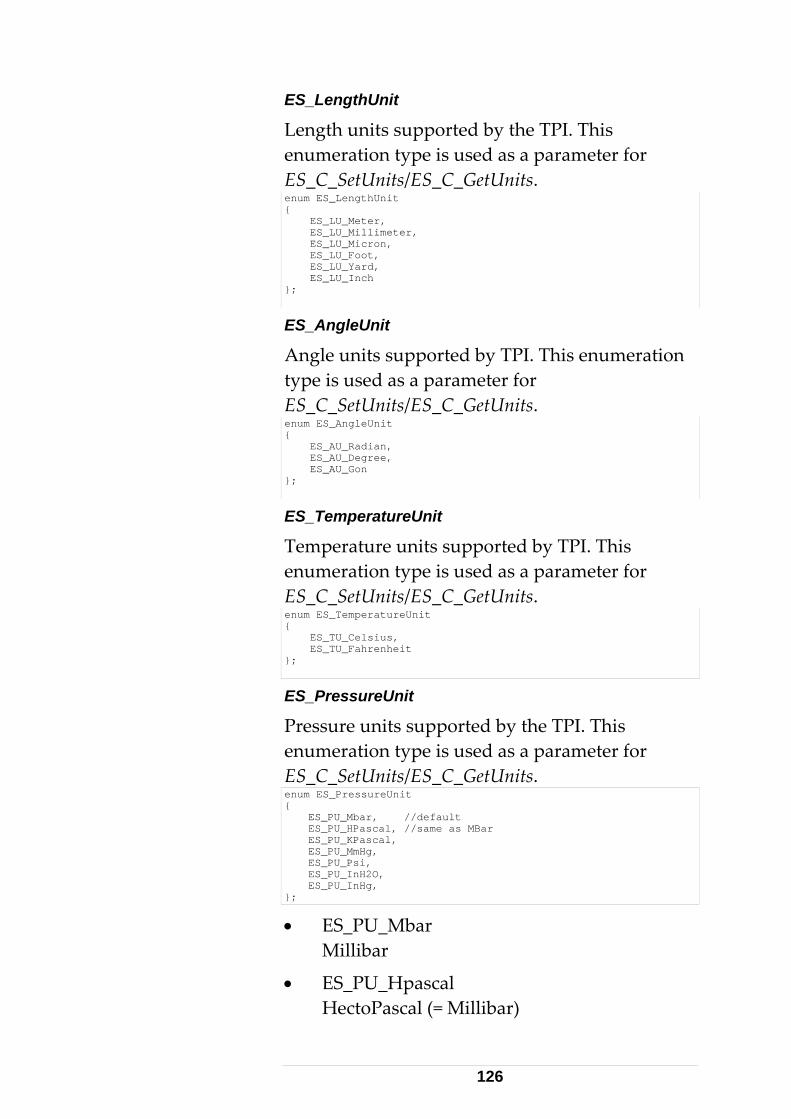
ES_LengthUnit
Length units supported by the TPI. This enumeration type is used as a parameter for ES_C_SetUnits/ES_C_GetUnits. enum ES_LengthUnit { ES_LU_Meter, ES_LU_Millimeter, ES_LU_Micron, ES_LU_Foot, ES_LU_Yard, ES_LU_Inch };
ES_AngleUnit
Angle units supported by TPI. This enumeration type is used as a parameter for ES_C_SetUnits/ES_C_GetUnits. enum ES_AngleUnit { ES_AU_Radian, ES_AU_Degree, ES_AU_Gon };
ES_TemperatureUnit
Temperature units supported by TPI. This enumeration type is used as a parameter for ES_C_SetUnits/ES_C_GetUnits. enum ES_TemperatureUnit { ES_TU_Celsius, ES_TU_Fahrenheit };
ES_PressureUnit
Pressure units supported by the TPI. This enumeration type is used as a parameter for ES_C_SetUnits/ES_C_GetUnits. enum ES_PressureUnit { ES_PU_Mbar, //default ES_PU_HPascal, //same as MBar ES_PU_KPascal, ES_PU_MmHg, ES_PU_Psi, ES_PU_InH2O, ES_PU_InHg, };
• ES_PU_Mbar Millibar
• ES_PU_Hpascal HectoPascal (= Millibar)
126
• ES_PU_Kpascal KiloPascal
• ES_PU_MmHg Millimeter Mercury
• ES_PU_Ps Pounds per Inch
• ES_PU_InH2O Inch Water Height
• ES_PU_InHg Inch Mercury
ES_HumidityUnit
Humidity units supported by the TPI. This enumeration type is used as parameter for ES_C_SetUnits/ES_C_GetUnits. enum ES_HumidityUnit { ES_HU_RH };
• ES_HU_RH Relative humidity, which is expressed in percentage.
ES_TrackerStatus
This enumeration type names the possible tracker states. It is used as the ES_C_GetTrackerStatus command parameter. The Tracker Status is related to the LED indicator on the tracker head. enum ES_TrackerStatus { ES_TS_NotReady, ES_TS_Busy, ES_TS_Ready, ES_TS_6DstatusInvalid, };
• ES_TS_NotReady Tracker not ready; currently not attached to a target.
• ES_TS_Busy Tracker is currently measuring.
• ES_TS_Ready Tracker attached to a target and is ready to measure.
127
• ES_TS_6DStatusInvalid 6D status of T‐Probe measurement is not valid
ES_ADMStatus
Additional information about the ADM of the laser tracker. This enumeration type is used as a parameter for ES_C_GetSystemStatus. enum ES_ADMStatus { ES_AS_NoADM, ES_AS_ADMCommFailed, ES_AS_ADMReady, ES_AS_ADMBusy, ES_AS_HWError, ES_AS_SecurityLockActive, ES_AS_NotCompensated, };
• ES_AS_NoADM Tracker not equipped with an ADM.
• ES_AS_ADMCommFailed Communication with ADM failed.
• ES_AS_ADMReady ADM is ready to measure.
• ES_AS_ADMBusy ADM is busy (performing a measurement).
• ES_AS_HWError Unspecified hardware error
• ES_AS_SecurityLockActive ADM has been locked for security because maximal allowed laser intensity has exceeded. Try to recover with powering off/on the controller. If problem persists, refer to Leica service.
• ES_AS_NotCompensated The ADM is not compensated and, if at all, may deliver inaccurate distances.
ES_NivelStatus
Additional information about the Leica ʹNivelʹ sensor connected to the laser tracker. This enumeration type is used as a result parameter for ES_C_StartNivelMeasurement.
128
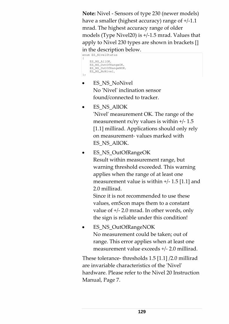
Note: Nivel ‐ Sensors of type 230 (newer models) have a smaller (highest accuracy) range of +/‐1.1 mrad. The highest accuracy range of older models (Type Nivel20) is +/‐1.5 mrad. Values that apply to Nivel 230 types are shown in brackets [] in the description below. enum ES_NivelStatus { ES_NS_AllOK, ES_NS_OutOfRangeOK, ES_NS_OutOfRangeNOK, ES_NS_NoNivel, };
• ES_NS_NoNivel No ʹNivelʹ inclination sensor found/connected to tracker.
• ES_NS_AllOK ʹNivelʹ measurement OK. The range of the measurement rx/ry values is within +/‐ 1.5 [1.1] millirad. Applications should only rely on measurement‐ values marked with ES_NS_AllOK.
• ES_NS_OutOfRangeOK Result within measurement range, but warning threshold exceeded. This warning applies when the range of at least one measurement value is within +/‐ 1.5 [1.1] and 2.0 millirad. Since it is not recommended to use these values, emScon maps them to a constant value of +/‐ 2.0 mrad. In other words, only the sign is reliable under this condition!
• ES_NS_OutOfRangeNOK No measurement could be taken; out of range. This error applies when at least one measurement value exceeds +/‐ 2.0 millirad.
These tolerance‐ thresholds 1.5 [1.1] /2.0 millirad are invariable characteristics of the ʹNivelʹ hardware. Please refer to the Nivel 20 Instruction Manual, Page 7.
129
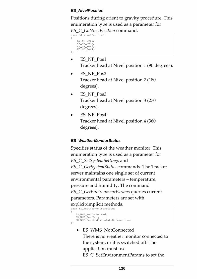
ES_NivelPosition
Positions during orient to gravity procedure. This enumeration type is used as a parameter for ES_C_GoNivelPosition command. enum ES_NivelPosition { ES_NP_Pos1, ES_NP_Pos2, ES_NP_Pos3, ES_NP_Pos4, };
• ES_NP_Pos1 Tracker head at Nivel position 1 (90 degrees).
• ES_NP_Pos2 Tracker head at Nivel position 2 (180 degrees).
• ES_NP_Pos3 Tracker head at Nivel position 3 (270 degrees).
• ES_NP_Pos4 Tracker head at Nivel position 4 (360 degrees).
ES_WeatherMonitorStatus
Specifies status of the weather monitor. This enumeration type is used as a parameter for ES_C_SetSystemSettings and ES_C_GetSystemStatus commands. The Tracker server maintains one single set of current environmental parameters – temperature, pressure and humidity. The command ES_C_GetEnvironmentParams queries current parameters. Parameters are set with explicit/implicit methods. enum ES_WeatherMonitorStatus { ES_WMS_NotConnected, ES_WMS_ReadOnly, ES_WMS_ReadAndCalculateRefractions, };
• ES_WMS_NotConnected There is no weather monitor connected to the system, or it is switched off. The application must use ES_C_SetEnvironmentParams to set the
130
environment parameters (explicit method). SetEnvironmentParams also updates the refraction parameters. Therefore, it is not necessary to use ‘ES_C_SetRefractionParams’. If ES_C_SetRefractionParams is called anyway, the refraction parameters are updated with the values provided, however, the next call to ES_C_SetEnvironmentParams will overwrite these values again.
• ES_WMS_ReadOnly While in this mode, if weather monitor is connected and correctly working, the system automatically reads the environmental values periodically (~ 20 seconds) from the monitor and internally updates the current environment parameters (implicit method). Error events repeatedly occur if no values can be read (weather monitor switched off, or cable connection broken). The ʹES_C_GetEnvironmentParamsʹ command can be used to retrieve the current values (Note: this command does not immediately trigger a measurement from the weather monitor – it just returns the emScon‐ internally buffered meteo values, i.e. those last read from the WM), while the command ʹES_C_SetEnvironmentParamsʹ is not available in this mode (Returns with an ‘usage conflict’ error). Refraction parameters are not influenced by the periodical update of environmental parameters. To change refraction values, an explicit ʹES_C_SetRefractionParamsʹ is required. The ʹES_WMS_ReadOnlyʹ mode is therefore suitable if the environmental
131
values come from the WM, but the application wants to use its own formula to calculate refraction parameters from these values. The mode of operation is hence as follows:
‐ ES_C_GetEnvironmentParams: delivers values last read from weather monitor.
‐ Calculate ADM and IFM refraction indices with application‐specific formula.
‐ Set the calculated refraction parameters with ES_C_SetRefractionParams.
This mode is therefore rarely used. The normal mode of operation is to use ʹES_WMS_ReadAndCalculateRefractionsʹ (see below).
• ES_WMS_ReadAndCalculateRefractions This is the normal mode of operation if using a weather monitor. It acts the same as the ʹES_WMS_ReadOnlyʹ mode, but in addition, the current refraction parameters are automatically recalculated and updated. The ʹES_C_GetEnvironmentParamsʹ and ʹES_C_GetRefractionParamsʹ commands can be used to retrieve the current values, while the ʹES_C_SetEnvironmentParamsʹ and ʹES_C_SetRefractionParamsʹ both are not available in this mode (would return with an ‘usage conflict’ error).
Attention: The weather monitor should be switched‐on before starting the emScon server. The weather monitor requires some initialization‐
132
time after switching on. If values are queried during this initialization phase, wrong values may be returned and the weather monitor remains in indifferent state. This is due to a problem of the weather monitor hardware. It is recommended to remove the battery from the weather monitor and always enable its power supply before, or at the same time, the emScon server gets booted. New behavior with emScon 3.0: With emScon 3.0, there is an automatic recognition of any attached meteo station and the system will automatically set related flags to a most common and reasonable state. See chapter Automatic External Device Recognition (under Section 2.4) for more details. ES_RegionType
This enumeration type is used as a parameter for regions . enum ES_RegionType { ES_RT_Sphere, ES_RT_Box, };
• ES_RT_Sphere Region type is a sphere.
• ES_RT_Box Region Type is a box.
ES_TrackerProcessorStatus
The sequence of this enum is important. It shows the state of the tracker processor during startup of the Tracker Server. The value issued describes the status of the startup procedure.
‐ The tracker can only be booted if there is a connection to emScon.
‐ It can have a valid compensation only if it is booted.
133
‐ It can be initialized only if it has a valid compensation.
‐ The tracker is ready only if it is initialized.
This enumeration type is used as a parameter of ES_C_GetSystemStatus. enum ES_TrackerProcessorStatus { ES_TPS_NoTPFound, ES_TPS_TPFound, ES_TPS_NBOpen, ES_TPS_Booted, ES_TPS_CompensationSet, ES_TPS_Initialized, };
• ES_TPS_NoTPFound No Tracker Processor could be recognized.
• ES_TPS_TPFound Tracker Processor is recognized, but connection from processor to tracker failed.
• ES_TPS_NBOpen Connection from processor to tracker is established, but booting failed.
• ES_TPS_Booted Tracker Processor booted, but there is no valid compensation.
• ES_TPS_CompensationSet Compensation set available, tracker not yet initialized.
• ES_TPS_Initialized Initialization was OK; tracker is ready.
ES_LaserProcessorStatus
Additional information about the laser processor. This enumeration type is used as a parameter for ES_C_GetSystemStatus. enum ES_LaserProcessorStatus { ES_LPS_LCPCommFailed, ES_LPS_LCPNotAvail, ES_LPS_LaserHeatingUp, ES_LPS_LaserReady, ES_LPS_UnableToStabilize, ES_LPS_LaserOff };
• ES_LPS_LCPCommFailed Communication to laser processor failed.
134

This indicates a hardware problem. Report to Leica service representative.
• ES_LPS_LCPNotAvail The Laser processor is not available. This indicates a hardware problem. Report to Leica service representative.
• ES_LPS_LaserHeatingUp Laser is warming up. This is the normal case after switching‐on the laser / controller (takes about 20 minutes).
• ES_LPS_LaserReady Laser is ready. From now on, the tracker can be used, but first needs to be initialized. See chapter ʹApplication Initial Stepsʹ. Note: There is an alternative of repeatedly polling with ʹES_C_GetSystemStatusʹ to figure out whether the laser is ready. As soon as the laser is ready, emScon issues a so‐ called ‘SystemStatusChange’ event. This is a packet of the type ʹES_DT_SystemStatusChangeʹ, containing a status parameter. In case of laser ready, this parameter is ʹES_SSC_LaserWarmedUpʹ.
• ES_LPS_UnableToStabilize Laser not able to stabilize. This probably indicates a rapidly changing (up and down) of the environment temperature or a wrong active Temperature Range. Make sure the tracker is used in an environment with stable temperature. This rarely happens. Usually the laser just takes a longer warm up phase if environment temperature is not that stable.
• ES_LPS_LaserOff The Laser is switched off. Use ‘ES_SwitchLaser’ to switch laser on.
135

ES_SystemStatusChange
Specifies status change types. This enumeration type is used as a parameter for ES_DT_SystemStatusChange notifications.
136
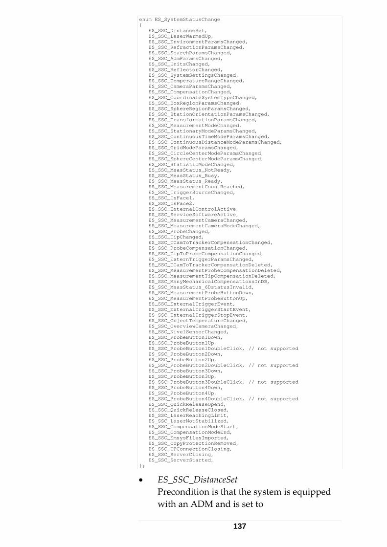
enum ES_SystemStatusChange { ES_SSC_DistanceSet, ES_SSC_LaserWarmedUp, ES_SSC_EnvironmentParamsChanged, ES_SSC_RefractionParamsChanged, ES_SSC_SearchParamsChanged, ES_SSC_AdmParamsChanged, ES_SSC_UnitsChanged, ES_SSC_ReflectorChanged, ES_SSC_SystemSettingsChanged, ES_SSC_TemperatureRangeChanged, ES_SSC_CameraParamsChanged, ES_SSC_CompensationChanged, ES_SSC_CoordinateSystemTypeChanged, ES_SSC_BoxRegionParamsChanged, ES_SSC_SphereRegionParamsChanged, ES_SSC_StationOrientationParamsChanged, ES_SSC_TransformationParamsChanged, ES_SSC_MeasurementModeChanged, ES_SSC_StationaryModeParamsChanged, ES_SSC_ContinuousTimeModeParamsChanged, ES_SSC_ContinuousDistanceModeParamsChanged, ES_SSC_GridModeParamsChanged, ES_SSC_CircleCenterModeParamsChanged, ES_SSC_SphereCenterModeParamsChanged, ES_SSC_StatisticModeChanged, ES_SSC_MeasStatus_NotReady, ES_SSC_MeasStatus_Busy, ES_SSC_MeasStatus_Ready, ES_SSC_MeasurementCountReached, ES_SSC_TriggerSourceChanged, ES_SSC_IsFace1, ES_SSC_IsFace2, ES_SSC_ExternalControlActive, ES_SSC_ServiceSoftwareActive, ES_SSC_MeasurementCameraChanged, ES_SSC_MeasurementCameraModeChanged, ES_SSC_ProbeChanged, ES_SSC_TipChanged, ES_SSC_TCamToTrackerCompensationChanged, ES_SSC_ProbeCompensationChanged, ES_SSC_TipToProbeCompensationChanged, ES_SSC_ExternTriggerParamsChanged, ES_SSC_TCamToTrackerCompensationDeleted, ES_SSC_MeasurementProbeCompensationDeleted, ES_SSC_MeasurementTipCompensationDeleted, ES_SSC_ManyMechanicalCompensationsInDB, ES_SSC_MeasStatus_6DstatusInvalid, ES_SSC_MeasurementProbeButtonDown, ES_SSC_MeasurementProbeButtonUp, ES_SSC_ExternalTriggerEvent, ES_SSC_ExternalTriggerStartEvent, ES_SSC_ExternalTriggerStopEvent, ES_SSC_ObjectTemperatureChanged, ES_SSC_OverviewCameraChanged, ES_SSC_NivelSensorChanged, ES_SSC_ProbeButton1Down, ES_SSC_ProbeButton1Up, ES_SSC_ProbeButton1DoubleClick, // not supported ES_SSC_ProbeButton2Down, ES_SSC_ProbeButton2Up, ES_SSC_ProbeButton2DoubleClick, // not supported ES_SSC_ProbeButton3Down, ES_SSC_ProbeButton3Up, ES_SSC_ProbeButton3DoubleClick, // not supported ES_SSC_ProbeButton4Down, ES_SSC_ProbeButton4Up, ES_SSC_ProbeButton4DoubleClick, // not supported ES_SSC_QuickReleaseOpend, ES_SSC_QuickReleaseClosed, ES_SSC_LaserReachingLimit, ES_SSC_LaserNotStabilized, ES_SSC_CompensationModeStart, ES_SSC_CompensationModeEnd, ES_SSC_EmsysFilesImported, ES_SSC_CopyProtectionRemoved, ES_SSC_TPConnectionClosing, ES_SSC_ServerClosing, ES_SSC_ServerStarted, };
• ES_SSC_DistanceSet Precondition is that the system is equipped with an ADM and is set to
137
‘KeepLastPosition’ (one of the parameters controlled by Set/GetSystemSettings). This event is fired as soon as the beam is (re‐) locked on to the target and an ADM measurement has been performed (a few seconds after the target has been placed to a stable position while beam attached). From now on, measurements can be continued. This mode is very convenient since it is not necessary to go back to the BirdBath after a beam break. For Probe (6DoF) measurements, the ‘KeepLastPosition’ flag MUST always be set as true! The ʹES_SCC_DistanceSetʹ event is not fired when the system flag ʹKeep Last Positionʹ is not set.
• ES_SSC_LaserWarmedUp This event is fired once the tracker is warmed up (after system / laser start, about 20 minutes after the laser was switched on). Also see description of enum ʹES_LaserProcessorStatusʹ. The laser processor status (warmed up or not) can also be queried in an active way (polling) by using ʹES_C_GetSystemStatusʹ.
• ES_SSC_XXX_Changed These events are fired whenever there is a change of one of the system settings (Parameters, Modes, Regions, Compensations) or Hardware (those detected automatically, such as TCam, Probe, Tip).
• ES_SSC_MeasStatus_NotReady
• ES_SSC_MeasStatus_Busy
• ES_SSC_MeasStatus_Ready This event informs about a Measurement Status change (Ready, Busy, Not Ready). Apart from evaluating these events, the
138
measurement status can also be asked actively with the command ’ES_C_GetTrackerStatus’. This information is typically used for user‐ interface purpose to implement a ‘traffic‐light’ with green (ready) / yellow (busy measuring) /red (target lost or missing compensation) colors.
• ES_SSC_MeasStatus_6DStatusInvalid Same comments as above. But only applies to probe measurements. Tracking is still OK, but the tilt of the probe is out of range so the TCam cannot reliably determine the rotation parameters. The rotation angles are not accurate and thus, the tip‐ coordinates not reliable. The recommended UI‐ color to assign to this status is blue (Used in BUI/ Compensation module).
• ES_SSC_MeasurementCountReached Stop a continuous measurement, when the max. number of measurements are reached.
• ES_SSC_IsFace1 This event is fired whenever the tracker changes to Face I.
• ES_SSC_IsFace2 This event is fired whenever the tracker changes to Face II.
• ES_SSC_ExternalControlActive This event is fired whenever the tracker server enters external control (e.g. Axyz ). While under external control, control through TPI commands are blocked.
• ES_SSC_ServiceSoftwareActive This event is fired whenever the tracker server runs with service software. While running service software, control through TPI commands is limited.
139
• ES_SSC_TcamToTrackerCompensation Deleted
• ES_SSC_MeasurementProbeCompensation Deleted
• ES_SSC_MeasurementTipCompensation Deleted Above three events inform about compensation deletion.
• ES_SSC_ManyMechanicalCompensations InDB
The recommended maximal number of mechanical compensations has been reached. Please delete some older compensations.
• ES_SSC_MeasurementProbeButtonDown This event is fired whenever one of the probe buttons (measurement trigger) is pressed. Exception: The system parameter ʹES_SP_ProbeConfig_Buttonʹ is set to ʹES_PCB_4ButtonModeʹ.
• ES_SSC_MeasurementProbeButtonUp This event is fired whenever the previously pressed probe button is released. Exception: The system parameter ʹES_SP_ProbeConfig_Buttonʹ is set to ʹES_PCB_4ButtonModeʹ.
• ES_SSC_ExternalTriggerEvent This event is fired whenever an external Trigger Pulse occurs.
• ES_SSC_ExternalTriggerStartEvent This event is fired whenever an external Trigger Start Pulse (trigger signal rising flank) occurs.
• ES_SSC_ExternalTriggerStopEvent This event is fired whenever an external
140
Trigger Stop Pulse (trigger signal falling flank) occurs.
• ES_SSC_ObjectTemperatureChanged
This event is fired when the object temperature has changed more than the tolerance value (since the last time this event was fired). The object temperature tolerance value is a System Parameter and must be set as ʹES_SP_D_ObjectTemperatureToleranceʹ, by using the ʹSetDoubleSystemParamterʹ command). See also description of ʹES_C_GetObjectTemperatureʹ command. The hardware configuration issues described there also apply here.
• ES_SSC_OverviewCameraChanged
This event is fired when an overview camera either gets removed or mounted to a tracker. An application then can use the ʹGetOverviewCameraInfoʹ command to get further information. Note: older hardware may not support this feature.
• ES_SSC_NivelSensorChanged
This event is fired when a ʹNivelʹ (inclination Sensor) either gets removed or mounted to a tracker. Note: older hardware may not support this feature.
• ES_SSC_ProbeButton1Down
• ES_SSC_ProbeButton1Up
• ES_SSC_ProbeButton2Down
• ES_SSC_ProbeButton2Up
• ES_SSC_ProbeButton3Down
• ES_SSC_ProbeButton3Up
• ES_SSC_ProbeButton4Down
• ES_SSC_ProbeButton4Up
141
The Probe button interface has been improved with emScon V2.3 in terms than each one of the 4 buttons can be addressed individually. This feature is disabled by default in order to keep compatibility with existing applications. To enable, set the system parameter ʹES_SP_ProbeConfig_Buttonʹ to ʹES_PCB_4ButtonModeʹ by using the ʹSetLongSystemParameterʹ command. The application will then get individual events for each button as listed above instead of the ordinary MeasurementProbeButtonDown/Up events.
• ES_SSC_ProbeButton1DoubleClick
• ES_SSC_ProbeButton2DoubleClick
• ES_SSC_ProbeButton3DoubleClick
• ES_SSC_ProbeButton4DoubleClick Double Clicks are not supported with current Probe Firmware revision.
• ES_SSC_QuickReleaseOpend Indicates an opening of the quick release. This event only applies to new AT series trackers.
• ES_SSC_QuickReleaseClosed Indicates closing of quick release. This event only applies to new AT series trackers.
• ES_SSC_LaserReachingLimit Indicates the laser is about to reach the limit of a temperature range. If this event is ignored, a LaserNotStabilized event may follow soon. This will then require to pause a few minutes with measuring until the laser is ready again. Alternatively, you may perform an initialize upon a ʹLaserReachingLimitʹ event. See also enum
142
ʹES_TrackerTemperatureRangeʹ. This event only applies to new AT series trackers.
• ES_SSC_LaserNotStabilized This event is issued when the laser has (automatically) changed temperature range (which should have preceeded by a ʹLaserReachingLimitʹ event). Must wait a few minutes until laser is ready again. Alternatively, an ʹInitializeʹ command can be issued (recommended). See also See also enum ʹES_TrackerTemperatureRangeʹ. This event only applies to new AT series trackers.
• E_SSC_CompensationModeStart
This event is fired when the system enters compensation mode. While the system is in compensation mode, ordinary commands are blocked and will return with a ʹSystem is in compensation modeʹ error. Setting the compensation mode is not a public TPI command and therefore not under control of the application programmer. However, if the compensation BUI is running or launched besides an application, it might be useful to the application to know when the system is in / enters / leaves compensation mode. This is an advanced programming issue.
• ES_SSC_CompensationModeEnd
This event is fired when the system leaves compensation mode. All ordinary TPI commands are available again. This is an advanced programming issue.
• ES_SSC_EmsysFilesImported This event is fired when a data‐ import has completed (For example sending
143
compensation data (.emsys files) to the server on using the transfer‐ client tool).
• ES_SSC_CopyProtectionRemoved This event is fired if the copy protection device (dongle) is removed. System control through TPI commands is locked.
• ES_SSC_TPConnectionClosing This event is fired if the server connection gets lost. Server control through TPI commands is no longer possible. Server probably needs a reboot.
• ES_SSC_ServerClosing This event is fired if the server software terminates gracefully while the connection is still established. Upon a server crash, this event cannot be expected.
• ES_SSC_ServerStarted, This event is fired if the server is has re‐started (supposed the connection was still established).
ES_StatisticMode
Specifies the current statistical mode. This enumeration type is used as a parameter for the ES_C_SetStatisticMode command. enum ES_StatisticMode { ES_SM_Standard, ES_SM_Extended };
• ES_SM_Standard This is the default. Single‐ and Multi‐ measurement results are provided with reduced statistical information (without covariance values). That is, the data structures SingleMeasResultT and MultiMeasResultT are used and are compatible with the structures used in earlier emScon versions.
144
• ES_SM_Extended Single‐ and Multi‐ measurement results are provided with enhanced statistical information (including covariance values). While this mode is activated, the data structures SingleMeasResult2T and MultiMeasResult2T are used. The only difference is that these ʹ2ʹ‐ versions contain extended (statistical) information. Applications passing measurements to the ʹCallTransformationʹ command should use the ʹ2ʹ‐ variants since the transformation routine requires these extended statistics. To maintain compatibility with earlier versions, Single/MultiMeasResultT have not been extended with additional parameters. Newer application should always use the Extended mode and therefore use all the ‘2’‐ version structures / handlers.
ES_StillImageFileType
Specifies the format of the still image. This enumeration type is used as a parameter for the ES_C_GetStillImage command. enum ES_StillImageFileType { ES_SI_Bitmap, ES_SI_Jpeg };
• ES_SI_Bitmap The image arrives in Bitmap format
• ES_SI_Jpeg The image arrives in Jpeg format. This format is not supported.
ES_TransResultType
Specifies the type of the Transformation Parameters. Depending on this setting, the transformation routine will provide the 7 result parameters in ‘inverse’ order. This enumeration type is used as a parameter for the
145
ES_C_Set/GetTransformationInputParams command. enum ES_TransResultType { ES_TR_AsTransformation, ES_TR_AsOrientation };
• ES_TR_AsTransformation The 7 parameters are provided to be used for a transformation from local to object (nominal) coordinate system.
• ES_TR_AsOrientation The 7 parameters are provided to be used as orientation parameters (ES_C_SetOrientationParameters).
ES_TrackerProcessorType
Specifies the controller type of the Tracker Processor in use (SMART, Embedded [LTController plus/base] etc.). ATC900 applies to new controller for AT series trackers. enum ES_TrackerProcessorType { ES_TT_Undefined, ES_TT_SMART310, ES_TT_LT_Controller, ES_TT_EmbeddedController, ES_TT_EmbeddedController600, ES_TT_ATC900, };
ES_TPMicroProcessorType
Specifies the microprocessor type of the Tracker Processor in use (i486, 686 etc.). enum ES_TPMicroProcessorType { ES_TPM_Undefined, ES_TPM_i486, ES_TPM_686 };
ES_LTSensorType
Specifies the type of sensors that are defined (LT300, LTD800, AT901‐LR etc.).
146
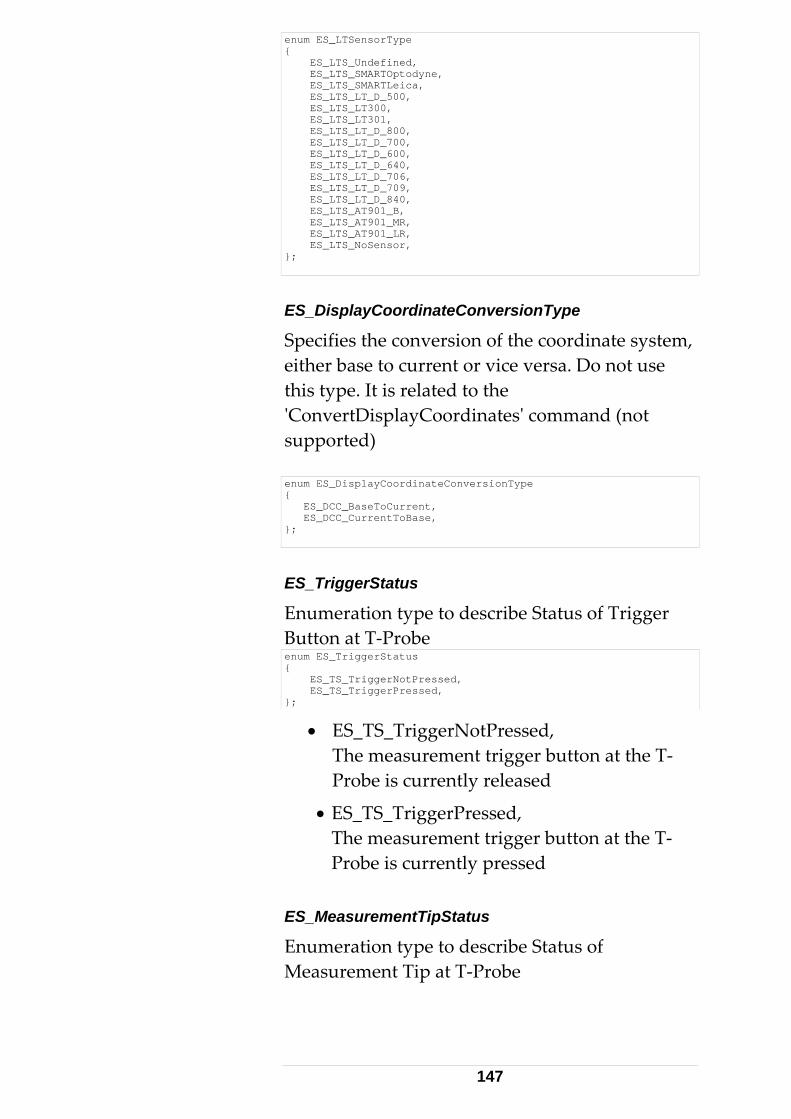
enum ES_LTSensorType { ES_LTS_Undefined, ES_LTS_SMARTOptodyne, ES_LTS_SMARTLeica, ES_LTS_LT_D_500, ES_LTS_LT300, ES_LTS_LT301, ES_LTS_LT_D_800, ES_LTS_LT_D_700, ES_LTS_LT_D_600, ES_LTS_LT_D_640, ES_LTS_LT_D_706, ES_LTS_LT_D_709, ES_LTS_LT_D_840, ES_LTS_AT901_B, ES_LTS_AT901_MR, ES_LTS_AT901_LR, ES_LTS_NoSensor, };
ES_DisplayCoordinateConversionType
Specifies the conversion of the coordinate system, either base to current or vice versa. Do not use this type. It is related to the ʹConvertDisplayCoordinatesʹ command (not supported) enum ES_DisplayCoordinateConversionType { ES_DCC_BaseToCurrent, ES_DCC_CurrentToBase, };
ES_TriggerStatus
Enumeration type to describe Status of Trigger Button at T‐Probe enum ES_TriggerStatus { ES_TS_TriggerNotPressed, ES_TS_TriggerPressed, };
• ES_TS_TriggerNotPressed, The measurement trigger button at the T‐Probe is currently released
• ES_TS_TriggerPressed, The measurement trigger button at the T‐Probe is currently pressed
ES_MeasurementTipStatus
Enumeration type to describe Status of Measurement Tip at T‐Probe
147
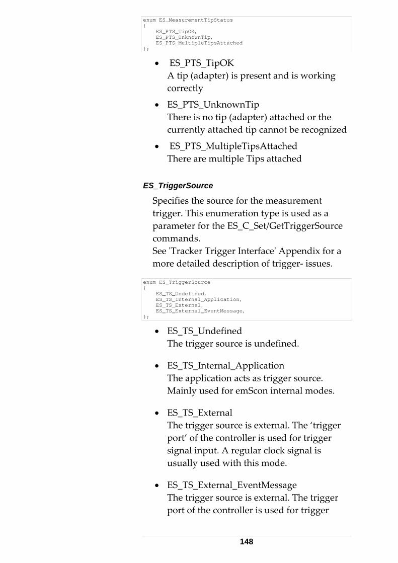
enum ES_MeasurementTipStatus { ES_PTS_TipOK, ES_PTS_UnknownTip, ES_PTS_MultipleTipsAttached };
• ES_PTS_TipOK A tip (adapter) is present and is working correctly
• ES_PTS_UnknownTip There is no tip (adapter) attached or the currently attached tip cannot be recognized
• ES_PTS_MultipleTipsAttached There are multiple Tips attached
ES_TriggerSource
Specifies the source for the measurement trigger. This enumeration type is used as a parameter for the ES_C_Set/GetTriggerSource commands. See ʹTracker Trigger Interfaceʹ Appendix for a more detailed description of trigger‐ issues.
enum ES_TriggerSource { ES_TS_Undefined, ES_TS_Internal_Application, ES_TS_External, ES_TS_External_EventMessage, };
• ES_TS_Undefined The trigger source is undefined.
• ES_TS_Internal_Application The application acts as trigger source. Mainly used for emScon internal modes.
• ES_TS_External The trigger source is external. The ‘trigger port’ of the controller is used for trigger signal input. A regular clock signal is usually used with this mode.
• ES_TS_External_EventMessage The trigger source is external. The trigger port of the controller is used for trigger
148
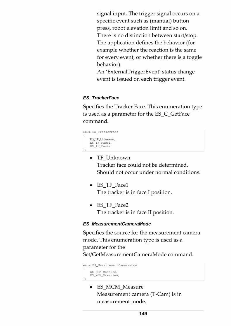
signal input. The trigger signal occurs on a specific event such as (manual) button press, robot elevation limit and so on. There is no distinction between start/stop. The application defines the behavior (for example whether the reaction is the same for every event, or whether there is a toggle behavior). An ‘ExternalTriggerEvent’ status change event is issued on each trigger event.
ES_TrackerFace
Specifies the Tracker Face. This enumeration type is used as a parameter for the ES_C_GetFace command.
enum ES_TrackerFace { ES_TF_Unknown, ES_TF_Face1, ES_TF_Face2 };
• TF_Unknown Tracker face could not be determined. Should not occur under normal conditions.
• ES_TF_Face1 The tracker is in face I position.
• ES_TF_Face2 The tracker is in face II position.
ES_MeasurementCameraMode
Specifies the source for the measurement camera mode. This enumeration type is used as a parameter for the Set/GetMeasurementCameraMode command.
enum ES_MeasurementCameraMode { ES_MCM_Measure, ES_MCM_Overview, };
• ES_MCM_Measure Measurement camera (T‐Cam) is in measurement mode.
149
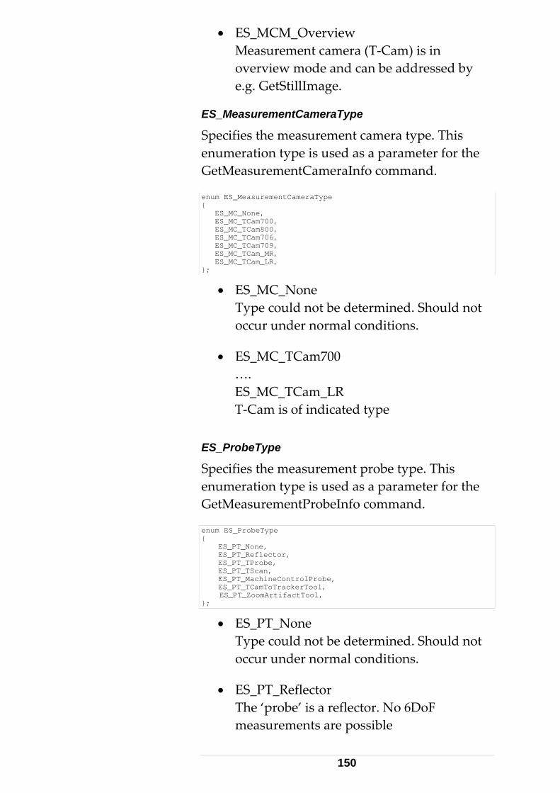
• ES_MCM_Overview Measurement camera (T‐Cam) is in overview mode and can be addressed by e.g. GetStillImage.
ES_MeasurementCameraType
Specifies the measurement camera type. This enumeration type is used as a parameter for the GetMeasurementCameraInfo command.
enum ES_MeasurementCameraType { ES_MC_None, ES_MC_TCam700, ES_MC_TCam800, ES_MC_TCam706, ES_MC_TCam709, ES_MC_TCam_MR, ES_MC_TCam_LR, };
• ES_MC_None Type could not be determined. Should not occur under normal conditions.
• ES_MC_TCam700 …. ES_MC_TCam_LR T‐Cam is of indicated type
ES_ProbeType
Specifies the measurement probe type. This enumeration type is used as a parameter for the GetMeasurementProbeInfo command.
enum ES_ProbeType { ES_PT_None, ES_PT_Reflector, ES_PT_TProbe, ES_PT_TScan, ES_PT_MachineControlProbe, ES_PT_TCamToTrackerTool, ES_PT_ZoomArtifactTool, };
• ES_PT_None Type could not be determined. Should not occur under normal conditions.
• ES_PT_Reflector The ‘probe’ is a reflector. No 6DoF measurements are possible
150
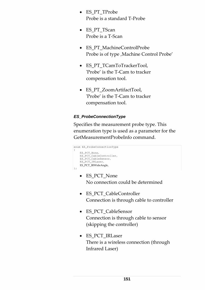
• ES_PT_TProbe Probe is a standard T‐Probe
• ES_PT_TScan Probe is a T‐Scan
• ES_PT_MachineControlProbe Probe is of type ‚Machine Control Probe’
• ES_PT_TCamToTrackerTool, ʹProbe’ is the T‐Cam to tracker compensation tool.
• ES_PT_ZoomArtifactTool, ʹProbe’ is the T‐Cam to tracker compensation tool.
ES_ProbeConnectionType
Specifies the measurement probe type. This enumeration type is used as a parameter for the GetMeasurementProbeInfo command.
enum ES_ProbeConnectionType { ES_PCT_None, ES_PCT_CableController, ES_PCT_CableSensor, ES_PCT_IRLaser, ES_PCT_IRWideAngle, };
• ES_PCT_None No connection could be determined
• ES_PCT_CableController Connection is through cable to controller
• ES_PCT_CableSensor Connection is through cable to sensor (skipping the controller)
• ES_PCT_IRLaser There is a wireless connection (through Infrared Laser)
151
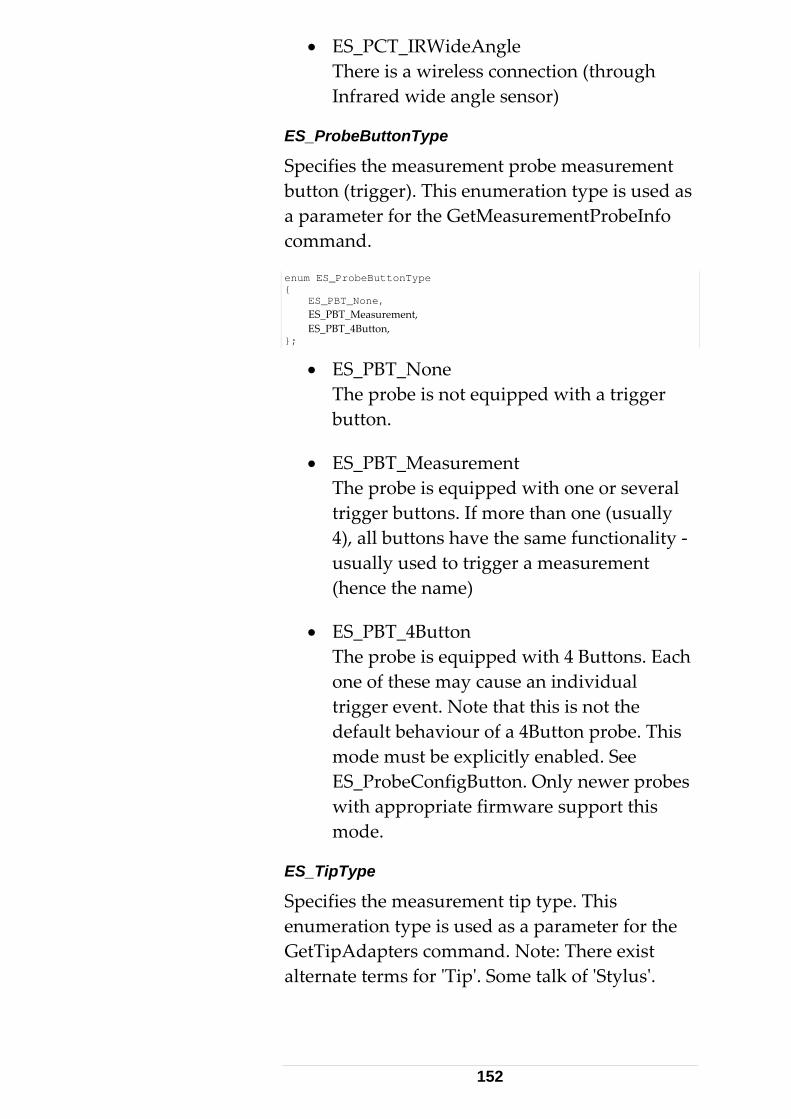
• ES_PCT_IRWideAngle There is a wireless connection (through Infrared wide angle sensor)
ES_ProbeButtonType
Specifies the measurement probe measurement button (trigger). This enumeration type is used as a parameter for the GetMeasurementProbeInfo command.
enum ES_ProbeButtonType { ES_PBT_None, ES_PBT_Measurement, ES_PBT_4Button, };
• ES_PBT_None The probe is not equipped with a trigger button.
• ES_PBT_Measurement The probe is equipped with one or several trigger buttons. If more than one (usually 4), all buttons have the same functionality ‐ usually used to trigger a measurement (hence the name)
• ES_PBT_4Button The probe is equipped with 4 Buttons. Each one of these may cause an individual trigger event. Note that this is not the default behaviour of a 4Button probe. This mode must be explicitly enabled. See ES_ProbeConfigButton. Only newer probes with appropriate firmware support this mode.
ES_TipType
Specifies the measurement tip type. This enumeration type is used as a parameter for the GetTipAdapters command. Note: There exist alternate terms for ʹTipʹ. Some talk of ʹStylusʹ.
152
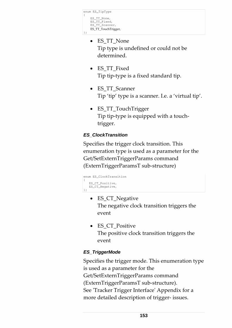
enum ES_TipType { ES_TT_None, ES_TT_Fixed, ES_TT_Scanner, ES_TT_TouchTrigger, };
• ES_TT_None Tip type is undefined or could not be determined.
• ES_TT_Fixed Tip tip‐type is a fixed standard tip.
• ES_TT_Scanner Tip ‘tip’ type is a scanner. I.e. a ‘virtual tip’.
• ES_TT_TouchTrigger Tip tip‐type is equipped with a touch‐trigger.
ES_ClockTransition
Specifies the trigger clock transition. This enumeration type is used as a parameter for the Get/SetExternTriggerParams command (ExternTriggerParamsT sub‐structure)
enum ES_ClockTransition { ES_CT_Positive, ES_CT_Negative, };
• ES_CT_Negative The negative clock transition triggers the event
• ES_CT_Positive The positive clock transition triggers the event
ES_TriggerMode
Specifies the trigger mode. This enumeration type is used as a parameter for the Get/SetExternTriggerParams command (ExternTriggerParamsT sub‐structure). See ʹTracker Trigger Interfaceʹ Appendix for a more detailed description of trigger‐ issues.
153
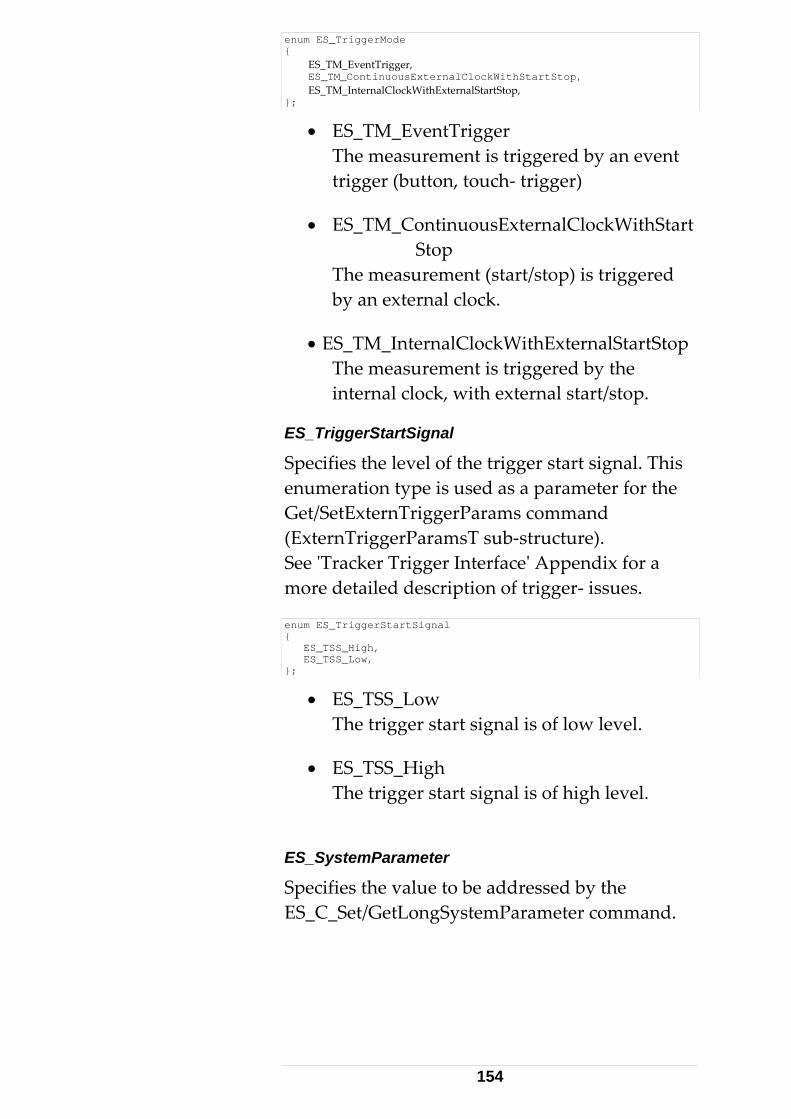
enum ES_TriggerMode { ES_TM_EventTrigger, ES_TM_ContinuousExternalClockWithStartStop, ES_TM_InternalClockWithExternalStartStop, };
• ES_TM_EventTrigger The measurement is triggered by an event trigger (button, touch‐ trigger)
• ES_TM_ContinuousExternalClockWithStart Stop The measurement (start/stop) is triggered by an external clock.
• ES_TM_InternalClockWithExternalStartStop The measurement is triggered by the internal clock, with external start/stop.
ES_TriggerStartSignal
Specifies the level of the trigger start signal. This enumeration type is used as a parameter for the Get/SetExternTriggerParams command (ExternTriggerParamsT sub‐structure). See ʹTracker Trigger Interfaceʹ Appendix for a more detailed description of trigger‐ issues.
enum ES_TriggerStartSignal { ES_TSS_High, ES_TSS_Low, };
• ES_TSS_Low The trigger start signal is of low level.
• ES_TSS_High The trigger start signal is of high level.
ES_SystemParameter
Specifies the value to be addressed by the ES_C_Set/GetLongSystemParameter command.
154
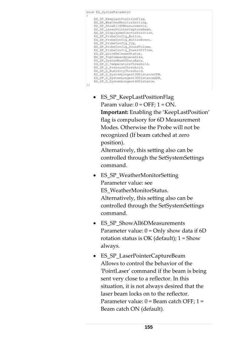
enum ES_SystemParameter { ES_SP_KeepLastPositionFlag, ES_SP_WeatherMonitorSetting, ES_SP_ShowAll6DMeasurements, ES_SP_LaserPointerCaptureBeam, ES_SP_DisplayReflectorPosition, ES_SP_ProbeConfig_Button, ES_SP_ProbeConfig_ButtonEvent, ES_SP_ProbeConfig_Tip, ES_SP_ProbeConfig_SoundVolume, ES_SP_ProbeConfig_PowerOffTime, ES_SP_QuickReleaseStatus, ES_SP_TcpCommandQueueSize, ES_SP_SystemMax6DDataRate, ES_SP_D_TemperatureThreshold, ES_SP_D_PressureThreshold, ES_SP_D_HumidityThreshold, ES_SP_D_SystemLongest3DDistanceIFM, ES_SP_D_SystemLongest3DDistanceADM, ES_SP_D_SystemLongest6DDistance, };
• ES_SP_KeepLastPositionFlag Param value: 0 = OFF; 1 = ON. Important: Enabling the ‘KeepLastPosition’ flag is compulsory for 6D Measurement Modes. Otherwise the Probe will not be recognized (If beam catched at zero position). Alternatively, this setting also can be controlled through the SetSystemSettings command.
• ES_SP_WeatherMonitorSetting Parameter value: see ES_WeatherMonitorStatus. Alternatively, this setting also can be controlled through the SetSystemSettings command.
• ES_SP_ShowAll6DMeasurements Parameter value: 0 = Only show data if 6D rotation status is OK (default); 1 = Show always.
• ES_SP_LaserPointerCaptureBeam Allows to control the behavior of the ʹPointLaserʹ command if the beam is being sent very close to a reflector. In this situation, it is not always desired that the laser beam locks on to the reflector. Parameter value: 0 = Beam catch OFF; 1 = Beam catch ON (default).
155
• ES_SP_DisplayReflectorPosition Parameter value: 0 = Disable Reflector Position Tracking (default); 1 = Enable Tracking. This setting also can be controlled through the SetSystemSettings command.
• ES_SP_ProbeConfig_Button Configures the behavior of the probe‐ buttons. Parameter values: see enum ES_ProbeConfigButton
• ES_SP_ProbeConfig_ButtonEvent Enables/disables events throwing on using the probe buttons. Parameter values: see enum ES_ProbeButtonEvent
• ES_SP_ProbeConfig_Tip Configure whether 6Dof measurements are allowed without a mounted Tip or not. Parameter values: enum ES_ProbeConfigTip
• ES_SP_ProbeConfig_SoundVolume Parameter values: volume as long, 0: No sound, 0..7 sound volume selected: 0 off, 1 (soft) – 7 (loud)
• ES_SP_ProbeConfig_PowerOffTime Time until probe automatically shuts off (if idle). Parameter values: time in minutes. valid range: 2..255.
• ES_SP_QuickReleaseStatus Indicates open/close status of Quick Release. Parameter values: see enum ES_QuickReleaseStatus
• ES_SP_TcpCommandQueueSize A value between 0 ... 10 can be set as command buffer‐ depth. Default is 0, i.e. command buffering is switched off.
• ES_SP_SystemMax6DDataRate. Cannot be set. Only ʹGet..ʹ supported. The
156
maximum measuring rate supported in 6DoF mode.
• ES_SP_D_TemperatureThreshold The Set/GetDoubleSystemParamter command must be used to handle this parameter. The value specifies the Temperature‐ threshold upon which, if reached, a ʹES_SSC_EnvironmentParamsChangedʹ (for Air‐ Temperature) and/or (if applies) a ʹES_SSC_ObjectTemperatureChangedʹ (for Object temperature) is thrown. Default threshold for temperature is 0.1 degree Celsius and is common for both, Air‐ and Object‐ temperature.
• ES_SP_D_PressureThreshold The Set/GetDoubleSystemParamter command must be used to handle this parameter. The value specifies the Pressure‐ threshold upon which, if reached, a ʹES_SSC_EnvironmentParamsChangedʹ is thrown. Default threshold for pressure is 1.0 hPa.
• ES_SP_D_HumidityThreshold The Set/GetDoubleSystemParamter command must be used to handle this parameter. The value specifies the Humidity‐ threshold upon which, if reached, a ʹES_SSC_EnvironmentParamsChangedʹ is thrown. Default threshold for pressure is 1.0 %.
• ES_SP_D_SystemLongest3DDistanceIFM Cannot be set. Only ʹGet..ʹ supported. Returns the longest distance (double parameter value) the interferometer is able to measure (which depends on tracker type).
157
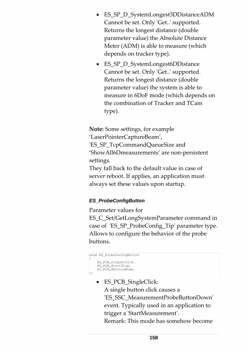
• ES_SP_D_SystemLongest3DDistanceADM Cannot be set. Only ʹGet..ʹ supported. Returns the longest distance (double parameter value) the Absolute Distance Meter (ADM) is able to measure (which depends on tracker type).
• ES_SP_D_SystemLongest6DDistance Cannot be set. Only ʹGet..ʹ supported. Returns the longest distance (double parameter value) the system is able to measure in 6DoF mode (which depends on the combination of Tracker and TCam type).
Note: Some settings, for example ‘LaserPointerCaptureBeam’, ʹES_SP_TcpCommandQueueSize and ‘ShowAll6Dmeasurements’ are non‐persistent settings. They fall back to the default value in case of server reboot. If applies, an application must always set these values upon startup. ES_ProbeConfigButton
Parameter values for ES_C_Set/GetLongSystemParameter command in case of ʹES_SP_ProbeConfig_Tipʹ parameter type. Allows to configure the behavior of the probe buttons. enum ES_ProbeConfigButton { ES_PCB_SingleClick, ES_PCB_StartStop, ES_PCB_4ButtonMode, };
• ES_PCB_SingleClick: A single button click causes a ʹES_SSC_MeasurementProbeButtonDownʹ event. Typically used in an application to trigger a ʹStartMeasurementʹ. Remark: This mode has somehow become
158
obsolete. An application can always use ʹES_PCB_StartStopʹ and then only evaluate either the Down‐ or the Up‐ Event or both. For that reason, the equivalent to ʹES_PCB_SingleClickʹ is no longer available in 4Button mode.
• ES_PCB_StartStop: A first button‐ click causes a ʹES_SSC_MeasurementProbeButtonDown ʹ event, releasing the button causes a ʹES_SSC_MeasurementProbeButtonUpʹ event. Typically used to perform a continuous measurement while the Button is being hold down (i.e. Start the measurement upon pressing the button and stop it on releasing button).
• ES_PCB_4ButtonMode: This mode has been introduced with emScon V2.3. It allows addressing each one of the 4 probe buttons individually. Behaves like ES_PCB_StartStop, but individually for each one of the four buttons. In addition, ʹdouble‐ clickʹ events have been defined for future issues. However, these are not supported so far (V3.0). Consequently, the following events are issued: ES_SSC_ProbeButton[1..4]Down, ES_SSC_ProbeButton[1..4]Up See enum ʹES_SystemStatusChangeʹ. The events ES_SSC_MeasurementProbeButtonDown and ES_SSC_MeasurementProbeButtonUp are void in 4Button mode. Only newer probes with appropriate firmware support this mode. See also ES_ProbeButtonType. Double‐click events are not yet available
159
with emScon versions V3.0.
ES_ProbeConfigTip
Parameter values for ES_C_Set/GetLongSystemParameter command in case of ES_SP_ProbeConfig_Tip parameter type. enum ES_ProbeConfigTip { ES_PCT_OnlyWithTip, ES_PCT_NoTipAllowed, ES_PCT_OnlyWithShankCompensation, };
• ES_PCT_OnlyWithTip: Probe requires a Tip attached to allow measuring.
• ES_PCT_NoTipAllowed: No tip required (Scanner‐ probes). System allows measuring without a tip.
• ES_PCT_OnlyWithShankCompensation: If ʹProbeConfigTipʹ is set to this value, a valid shank‐ compensation must exist. Otherwise the system will not get ready (ʹgreenʹ) for measuring. This setting thus can be used by an application to force a shank‐ compensation, if applies. Note: If a shank compensation exists for a particular tip, but ʹES_PCT_OnlyWithShankCompensationʹ is not set, the measurements will nevertheless be corrected by the shank compensation values! This setting does therefore not mean to enable/disable an (existing) shank compensation! It is just thought as a ʹsecurity‐ switchʹ for applications that must have valid shank compensations in order to block measurements if the shank compensation is missing!
160
ES_ProbeButtonEvent
Parameter values for the ES_C_Set/GetLongSystemParameter command in case of ES_SP_ProbeConfig_ButtonEvent parameter type. enum ES_ProbeButtonEvent { ES_PBE_DisableEvents, ES_PBE_EnableEvents, };
• ES_PBE_DisableEvents: no button events are sent
• ES_PBE_EnableEvents: server sends button events
ES_QuickReleaseStatus
Parameter values for the ES_C_GetLongSystemParameter command in case of ES_SP_QuickReleaseStatus parameter type. enum ES_QuickReleaseStatus { ES_QRS_Closed, ES_QRS_Open, };
• ES_QRS_Closed: Quick release is closed (OK to continue with tracker operations)
• ES_QRS_Open: Quick release is open (Must first close in order to continue with tracker operations)
ES_MeasurementStatusInfo
The values of this enum can be used to identify/mask each individual bit of the long parameter delivered by the command ES_C_GetMeasurementStatusInfo. Hence the power of 2 of every value. The meaning of the values should be self‐explaining according to their symbol‐names. See description of command
161
ES_C_GetMeasurementStatusInfo for further information. enum ES_MeasurementStatusInfo { ES_MSI_Unknown = 0, ES_MSI_TrackerFound = 1, ES_MSI_TrackerCompensationFound = 2, ES_MSI_ADMFound = 4, ES_MSI_ADMCompensationFound = 8, ES_MSI_MeasurementCameraFound = 16, ES_MSI_InternalCameraParamsOK = 32, ES_MSI_CameraToTrackerParamsFound = 64, ES_MSI_MeasurementProbeFound = 128, ES_MSI_ProbeParamsFound = 256, ES_MSI_MeasurementTipFound = 512, ES_MSI_TipParamsFound = 1024, ES_MSI_ReflectorFound = 2048, ES_MSI_InFace1 = 4096, ES_MSI_ShankParamsFound = 8192, };
ES_ClearCommandQueueType
This type is used as input‐ parameter for the ʹClearCommandQueueʹ command. See struct ClearCommandQueueCT. Clearing command buffers is only an issue when the ES_SP_TcpCommandQueueSize system parameter is set > 0 and usually only if a fatal error has happened upon which we want to stop the command execution immediately. This is an advanced programming feature. enum ES_ClearCommandQueueType { ES_CCQ_ClearOwnOnly, ES_CCQ_ClearAll, };
• ES_CCQ_ClearOwnOnly: Clear only those commands from the queue that were placed by the owning application. Do not remove commands that have been placed by other clients. This is an issue if several clients are connected to the server at a time.
• ES_CCQ_ClearAll: Clear all pending commands, regardless which application placed them.
ES_OverviewCameraType
This enum is part of the result of a ʹGetOverviewCameraInfoʹ command. See struct
162
GetOverviewCameraInfoRT. It shows the type of the mounted overview camera. enum ES_OverviewCameraType { ES_OCT_Unknown, ES_OCT_Classic, ES_OCT_TCam_Integrated, // overview camera in TCam stand };
• ES_OCT_Unknown: None or a non‐ recognizable Overview Camera is mounted.
• ES_OCT_Classic A classic ʹstandaloneʹ Overview Camera is mounted on the tracker.
• ES_OCT_TCam_Intergrated A T‐Cam with integrated Overview Camera is installed. Note: This is a hardware option ‐ Not all T‐Cams have an integrated overview camera.
ES_TriggerCardType
This enum is part of the result of a ʹGetTriggerBoardInfoʹ command. See struct GetTriggerBoardInfRT. It shows the type of the mounted trigger board. enum ES_TriggerCardType { ES_TCT_None, ES_TCT_SingleTracker, };
• ES_TCT_None The system is not equipped with a Trigger Board.
• ES_TCT_SingleTracker The system is equipped with a single Tracker Trigger Board.
Multi‐ Tracker Boards are not yet supported. ES_ADMType
Specifies the type of the Absolute Distance Meter.
163
enum ES_ADMType { ES_AMT_Unknown, ES_AMT_LeicaADM, ES_AMT_LeicaAIFM, };
• ES_AMT_Unknown The type is unknown or cannot be determined.
• ES_AMT_ LeicaADM The ADM is a Leica type ADM.
• ES_AMT_ LeicaAIFM The tracker is equipped with an ʹabsolute interferometerʹ ADM type.
ES_TrkAccuracyModel
Specifies the accuracy model of the tracker. enum ES_TrkAccuracyModel { ES_TAM_Unknown, ES_TAM_2005, };
• ES_TAM_Unknown The accuracy model cannot be determined. This is mostly due to old firmware.
• ES_TAM_2005 The accuracy model represents the revision from 2005.
ES_NivelType
Specifies the type of the ʹNivelʹ inclination sensor. Note that the ʹrange of most precise measurementʹ of the Nivel 230 is smaller [1.1 mrad] than the one of the Nivel 20 [1.5 mrad]. Details see Nivel hardware Manuals. enum ES_NivelType { ES_NT_Unknown, ES_NT_Nivel20, ES_NT_Nivel230, };
• ES_NT_Unknown The ʹNivelʹ type is unknown or cannot be determined.
164
• ES_NT_Nivel20 The type is a ʹclassicʹ Nivel20 inclination sensor.
• ES_NT_Nivel230 The type is of a new Nivel230 (released 2005)
ES_TipToProbeCompensationType
Specifies the type of the TipToProbe Compensation. See command ʹGetTipToProbeCompensations2ʹ where this parameter is delivered. enum ES_TipToProbeCompensationType { ES_TCT_Unknown, ES_TCT_TipOnly, ES_TCT_ShankEnabled, };
• ES_TCT_Unknown The type of the TipToProbe compensation could not be determined.
• ES_TCT_TipOnly There exists only a Tip compensation
• ES_TCT_ShankEnabled A Tip and a Shank compensation exists. Note: The option ʹShank compensation onlyʹ (i.e. without Tip compensation) is not possible.
165
3.4 Data Structures This section describes all data structures defined in ES_C_API_Def.h. The data structures describe the ʹlayoutʹ of the data packets (byte arrays) to be transmitted over the TCP/IP network. The structures are required to construct and send data packets, to mask incoming data packets in order to recognize their type and to interpret their contents.
Note the 4‐Byte alignment prerequisite for the Tracker Server and the client. See #pragma pack (push, 4) in file ES_C_API_Def.h. The ʹpragma packʹ is a Microsoft specific C‐language extension. A 4‐Byte alignment may be different for other C/C++ compilers. No change of layout ( # of bytes and alignment for each member) is permitted, during translation of these structures to other languages.
There is a short general description for each type. Not all members are described in detail. Data members are often self‐ explanatory, while enumeration‐type members have been described under Enumeration Types. Struct variable descriptions are provided only where necessary.
Parameters are always in current units and coordinate system / CS‐type (where applicable) – unless specified otherwise. 3.4.1 Basic Data Structures This section describes those data structures that are not directly exchanged as packets. They are used as sub‐structures to compose the real ʹPacketʹ data types.
166
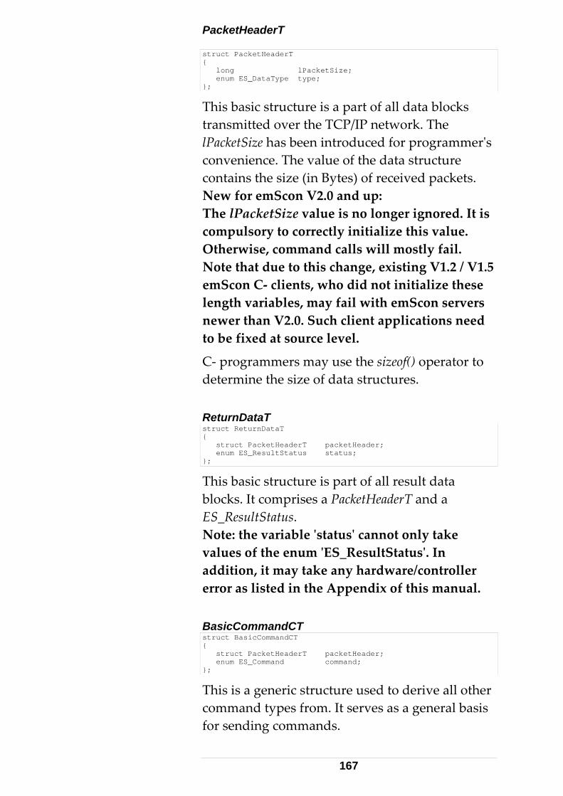
PacketHeaderT struct PacketHeaderT { long lPacketSize; enum ES_DataType type; };
This basic structure is a part of all data blocks transmitted over the TCP/IP network. The lPacketSize has been introduced for programmerʹs convenience. The value of the data structure contains the size (in Bytes) of received packets. New for emScon V2.0 and up: The lPacketSize value is no longer ignored. It is compulsory to correctly initialize this value. Otherwise, command calls will mostly fail. Note that due to this change, existing V1.2 / V1.5 emScon C‐ clients, who did not initialize these length variables, may fail with emScon servers newer than V2.0. Such client applications need to be fixed at source level.
C‐ programmers may use the sizeof() operator to determine the size of data structures. ReturnDataT struct ReturnDataT { struct PacketHeaderT packetHeader; enum ES_ResultStatus status; };
This basic structure is part of all result data blocks. It comprises a PacketHeaderT and a ES_ResultStatus. Note: the variable ʹstatusʹ cannot only take values of the enum ʹES_ResultStatusʹ. In addition, it may take any hardware/controller error as listed in the Appendix of this manual. BasicCommandCT struct BasicCommandCT { struct PacketHeaderT packetHeader; enum ES_Command command; };
This is a generic structure used to derive all other command types from. It serves as a general basis for sending commands.
167
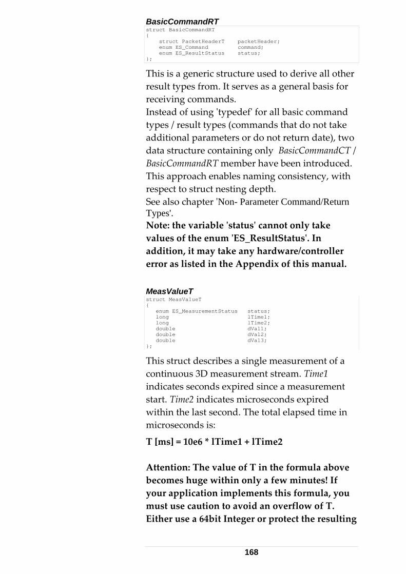
BasicCommandRT struct BasicCommandRT { struct PacketHeaderT packetHeader; enum ES_Command command; enum ES_ResultStatus status; };
This is a generic structure used to derive all other result types from. It serves as a general basis for receiving commands. Instead of using ʹtypedefʹ for all basic command types / result types (commands that do not take additional parameters or do not return date), two data structure containing only BasicCommandCT / BasicCommandRT member have been introduced. This approach enables naming consistency, with respect to struct nesting depth. See also chapter ʹNon- Parameter Command/Return Types'. Note: the variable ʹstatusʹ cannot only take values of the enum ʹES_ResultStatusʹ. In addition, it may take any hardware/controller error as listed in the Appendix of this manual. MeasValueT struct MeasValueT { enum ES_MeasurementStatus status; long lTime1; long lTime2; double dVal1; double dVal2; double dVal3; };
This struct describes a single measurement of a continuous 3D measurement stream. Time1 indicates seconds expired since a measurement start. Time2 indicates microseconds expired within the last second. The total elapsed time in microseconds is:
T [ms] = 10e6 * lTime1 + lTime2 Attention: The value of T in the formula above becomes huge within only a few minutes! If your application implements this formula, you must use caution to avoid an overflow of T. Either use a 64bit Integer or protect the resulting
168
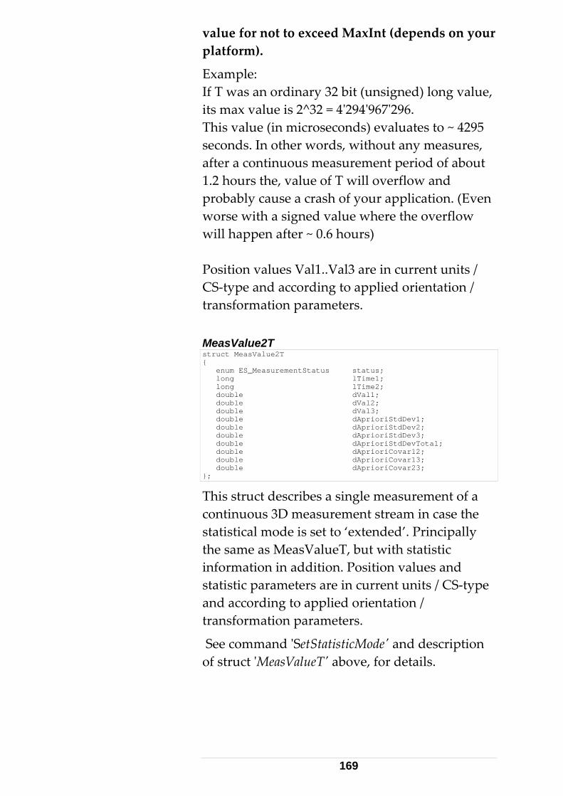
value for not to exceed MaxInt (depends on your platform).
Example: If T was an ordinary 32 bit (unsigned) long value, its max value is 2^32 = 4ʹ294ʹ967ʹ296. This value (in microseconds) evaluates to ~ 4295 seconds. In other words, without any measures, after a continuous measurement period of about 1.2 hours the, value of T will overflow and probably cause a crash of your application. (Even worse with a signed value where the overflow will happen after ~ 0.6 hours) Position values Val1..Val3 are in current units / CS‐type and according to applied orientation / transformation parameters. MeasValue2T struct MeasValue2T { enum ES_MeasurementStatus status; long lTime1; long lTime2; double dVal1; double dVal2; double dVal3; double dAprioriStdDev1; double dAprioriStdDev2; double dAprioriStdDev3; double dAprioriStdDevTotal; double dAprioriCovar12; double dAprioriCovar13; double dAprioriCovar23; };
This struct describes a single measurement of a continuous 3D measurement stream in case the statistical mode is set to ‘extended’. Principally the same as MeasValueT, but with statistic information in addition. Position values and statistic parameters are in current units / CS‐type and according to applied orientation / transformation parameters.
See command ʹSetStatisticModeʹ and description of struct ʹMeasValueTʹ above, for details.
169
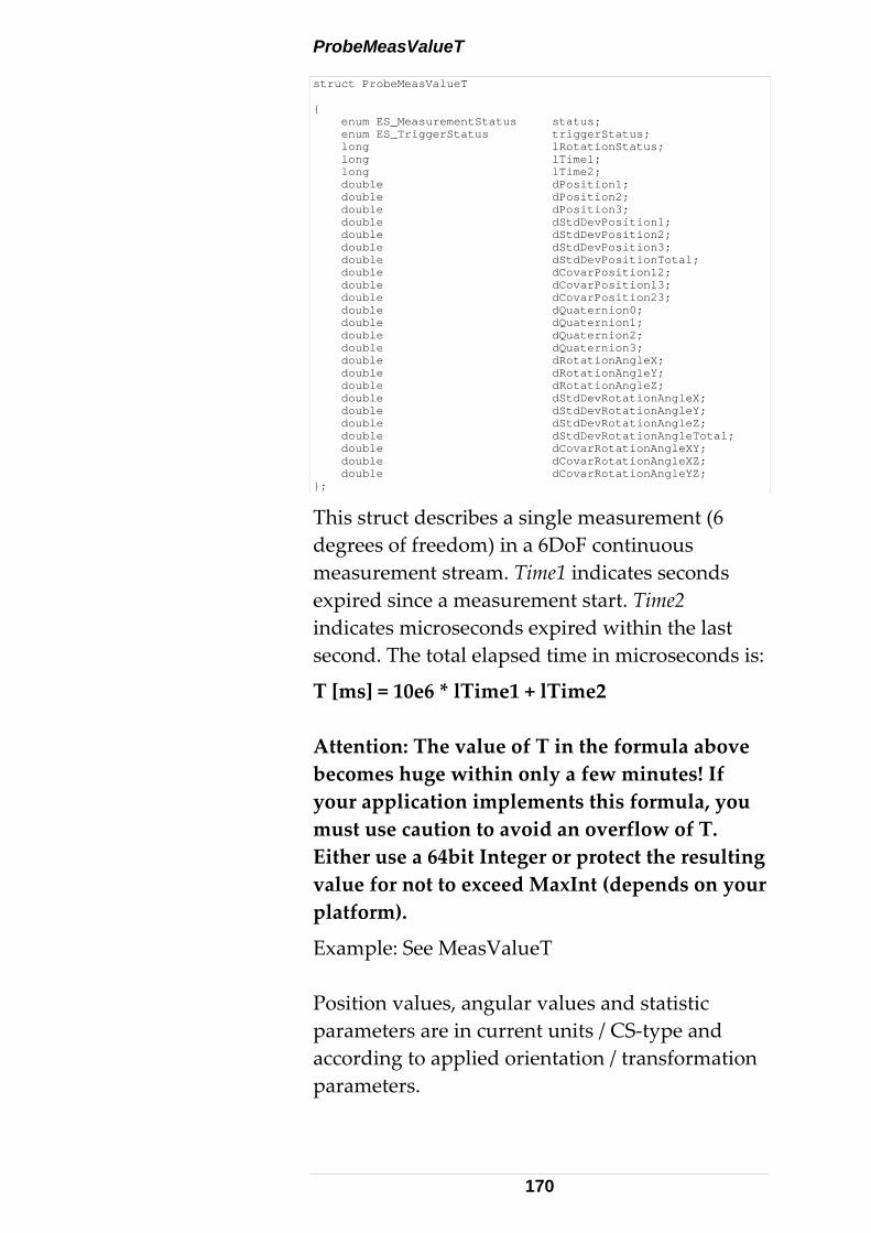
ProbeMeasValueT struct ProbeMeasValueT { enum ES_MeasurementStatus status; enum ES_TriggerStatus triggerStatus; long lRotationStatus; long lTime1; long lTime2; double dPosition1; double dPosition2; double dPosition3; double dStdDevPosition1; double dStdDevPosition2; double dStdDevPosition3; double dStdDevPositionTotal; double dCovarPosition12; double dCovarPosition13; double dCovarPosition23; double dQuaternion0; double dQuaternion1; double dQuaternion2; double dQuaternion3; double dRotationAngleX; double dRotationAngleY; double dRotationAngleZ; double dStdDevRotationAngleX; double dStdDevRotationAngleY; double dStdDevRotationAngleZ; double dStdDevRotationAngleTotal; double dCovarRotationAngleXY; double dCovarRotationAngleXZ; double dCovarRotationAngleYZ; };
This struct describes a single measurement (6 degrees of freedom) in a 6DoF continuous measurement stream. Time1 indicates seconds expired since a measurement start. Time2 indicates microseconds expired within the last second. The total elapsed time in microseconds is:
T [ms] = 10e6 * lTime1 + lTime2 Attention: The value of T in the formula above becomes huge within only a few minutes! If your application implements this formula, you must use caution to avoid an overflow of T. Either use a 64bit Integer or protect the resulting value for not to exceed MaxInt (depends on your platform).
Example: See MeasValueT Position values, angular values and statistic parameters are in current units / CS‐type and according to applied orientation / transformation parameters.
170
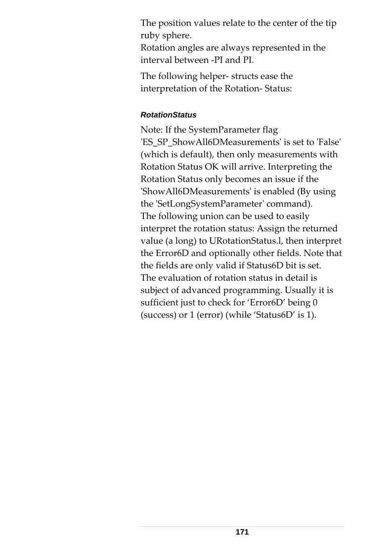
The position values relate to the center of the tip ruby sphere. Rotation angles are always represented in the interval between ‐PI and PI.
The following helper‐ structs ease the interpretation of the Rotation‐ Status: RotationStatus
Note: If the SystemParameter flag ʹES_SP_ShowAll6DMeasurementsʹ is set to ʹFalseʹ (which is default), then only measurements with Rotation Status OK will arrive. Interpreting the Rotation Status only becomes an issue if the ʹShowAll6DMeasurementsʹ is enabled (By using the ʹSetLongSystemParameterʹ command). The following union can be used to easily interpret the rotation status: Assign the returned value (a long) to URotationStatus.l, then interpret the Error6D and optionally other fields. Note that the fields are only valid if Status6D bit is set. The evaluation of rotation status in detail is subject of advanced programming. Usually it is sufficient just to check for ‘Error6D’ being 0 (success) or 1 (error) (while ‘Status6D’ is 1).
171
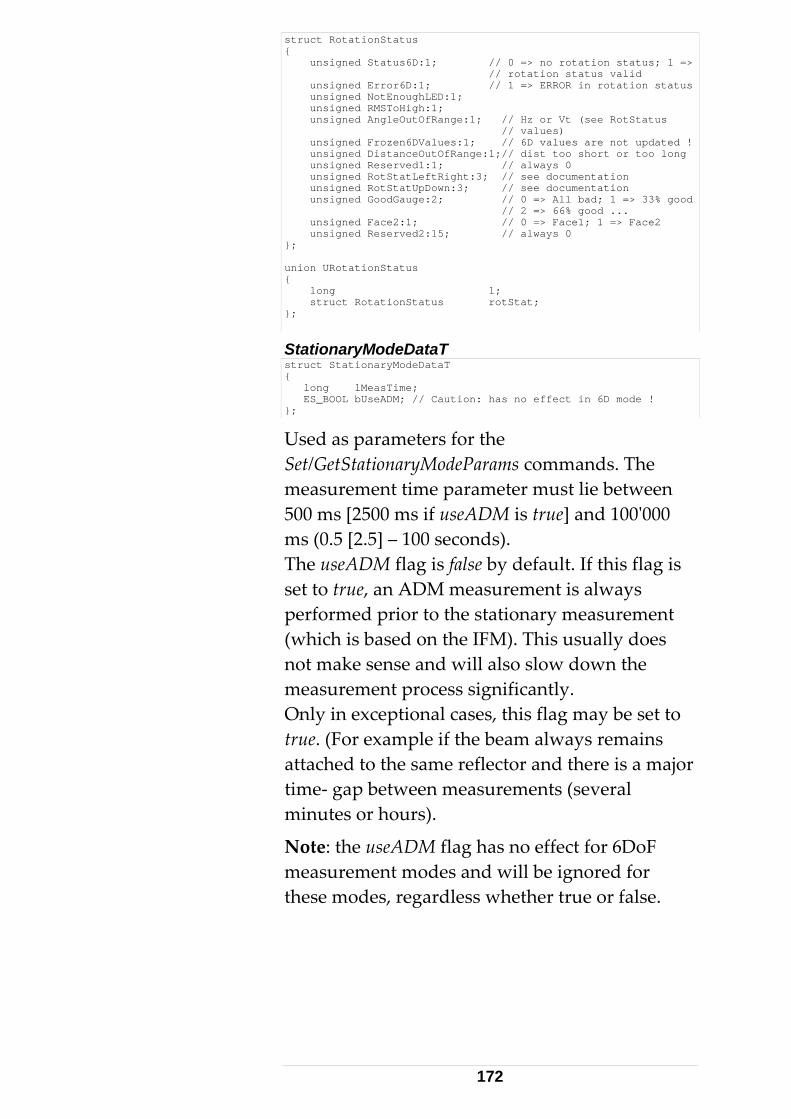
struct RotationStatus { unsigned Status6D:1; // 0 => no rotation status; 1 => // rotation status valid unsigned Error6D:1; // 1 => ERROR in rotation status unsigned NotEnoughLED:1; unsigned RMSToHigh:1; unsigned AngleOutOfRange:1; // Hz or Vt (see RotStatus // values) unsigned Frozen6DValues:1; // 6D values are not updated ! unsigned DistanceOutOfRange:1;// dist too short or too long unsigned Reserved1:1; // always 0 unsigned RotStatLeftRight:3; // see documentation unsigned RotStatUpDown:3; // see documentation unsigned GoodGauge:2; // 0 => All bad; 1 => 33% good // 2 => 66% good ... unsigned Face2:1; // 0 => Face1; 1 => Face2 unsigned Reserved2:15; // always 0 }; union URotationStatus { long l; struct RotationStatus rotStat; };
StationaryModeDataT struct StationaryModeDataT { long lMeasTime; ES_BOOL bUseADM; // Caution: has no effect in 6D mode ! };
Used as parameters for the Set/GetStationaryModeParams commands. The measurement time parameter must lie between 500 ms [2500 ms if useADM is true] and 100ʹ000 ms (0.5 [2.5] – 100 seconds). The useADM flag is false by default. If this flag is set to true, an ADM measurement is always performed prior to the stationary measurement (which is based on the IFM). This usually does not make sense and will also slow down the measurement process significantly. Only in exceptional cases, this flag may be set to true. (For example if the beam always remains attached to the same reflector and there is a major time‐ gap between measurements (several minutes or hours).
Note: the useADM flag has no effect for 6DoF measurement modes and will be ignored for these modes, regardless whether true or false.
172
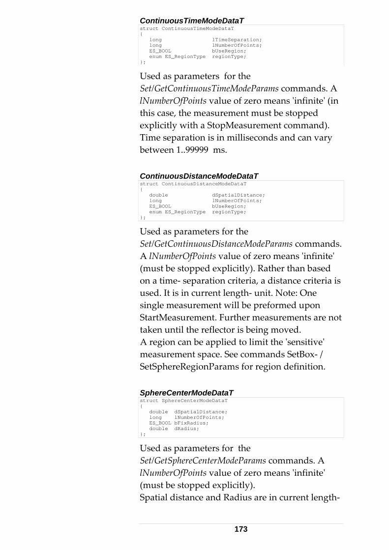
ContinuousTimeModeDataT struct ContinuousTimeModeDataT { long lTimeSeparation; long lNumberOfPoints; ES_BOOL bUseRegion; enum ES_RegionType regionType; };
Used as parameters for the Set/GetContinuousTimeModeParams commands. A lNumberOfPoints value of zero means ʹinfiniteʹ (in this case, the measurement must be stopped explicitly with a StopMeasurement command). Time separation is in milliseconds and can vary between 1..99999 ms. ContinuousDistanceModeDataT struct ContinuousDistanceModeDataT { double dSpatialDistance; long lNumberOfPoints; ES_BOOL bUseRegion; enum ES_RegionType regionType; };
Used as parameters for the Set/GetContinuousDistanceModeParams commands. A lNumberOfPoints value of zero means ʹinfiniteʹ (must be stopped explicitly). Rather than based on a time‐ separation criteria, a distance criteria is used. It is in current length‐ unit. Note: One single measurement will be preformed upon StartMeasurement. Further measurements are not taken until the reflector is being moved. A region can be applied to limit the ʹsensitiveʹ measurement space. See commands SetBox‐ / SetSphereRegionParams for region definition. SphereCenterModeDataT struct SphereCenterModeDataT { double dSpatialDistance; long lNumberOfPoints; ES_BOOL bFixRadius; double dRadius; };
Used as parameters for the Set/GetSphereCenterModeParams commands. A lNumberOfPoints value of zero means ʹinfiniteʹ (must be stopped explicitly). Spatial distance and Radius are in current length‐
173
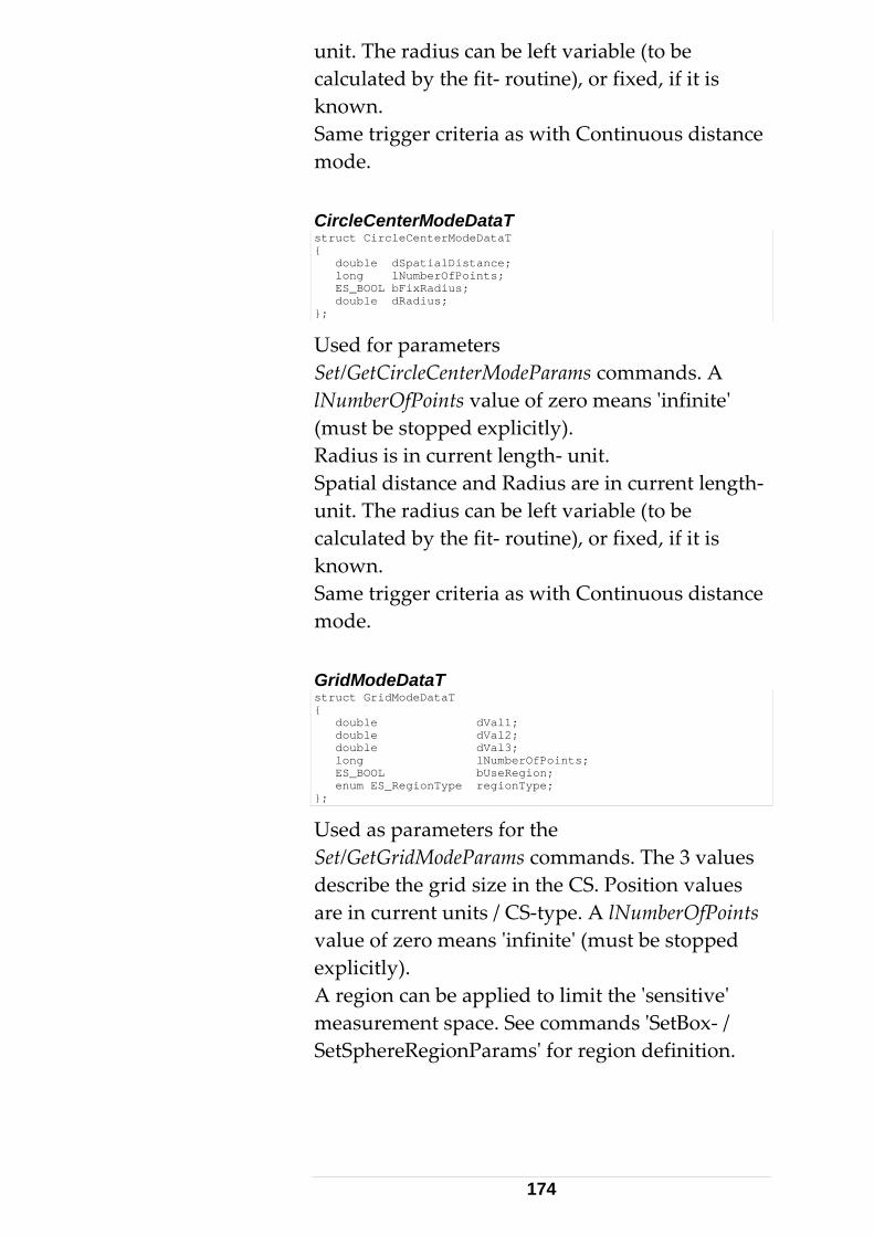
unit. The radius can be left variable (to be calculated by the fit‐ routine), or fixed, if it is known. Same trigger criteria as with Continuous distance mode. CircleCenterModeDataT struct CircleCenterModeDataT { double dSpatialDistance; long lNumberOfPoints; ES_BOOL bFixRadius; double dRadius; };
Used for parameters Set/GetCircleCenterModeParams commands. A lNumberOfPoints value of zero means ʹinfiniteʹ (must be stopped explicitly). Radius is in current length‐ unit. Spatial distance and Radius are in current length‐ unit. The radius can be left variable (to be calculated by the fit‐ routine), or fixed, if it is known. Same trigger criteria as with Continuous distance mode. GridModeDataT struct GridModeDataT { double dVal1; double dVal2; double dVal3; long lNumberOfPoints; ES_BOOL bUseRegion; enum ES_RegionType regionType; };
Used as parameters for the Set/GetGridModeParams commands. The 3 values describe the grid size in the CS. Position values are in current units / CS‐type. A lNumberOfPoints value of zero means ʹinfiniteʹ (must be stopped explicitly). A region can be applied to limit the ʹsensitiveʹ measurement space. See commands ʹSetBox‐ / SetSphereRegionParamsʹ for region definition.
174
SearchParamsDataT struct SearchParamsDataT { double dSearchRadius; double lTimeOut; };
Used for parameters of Set/GetSearchParams commands. The search process is aborted upon one or the other of the two criteria is reached. TimeOut is in milliseconds. There is a minimum value of 10’000 ms (10 Seconds) and a maximum of 240ʹ000 ms (4 minutes). SearchRadius is in current units. The timeout parameter will interrupt the search if it takes too long due to a too big search radius (if no reflector found within the specified time). The Search Radius in current length units and must lie between 0 and 0.5 meters. The default value is 0.04 meters. (Caution with small or even zero radius and / or small timeOut: Too small value may cause the search process to fail. Note: the maximum radius value was 1.0 m in emScon versions prior to version 2.0 and has been reduced to 0.5 m for newer versions! Large search radii result in extended search times, unless time is limited to a reasonable value. Typical values are 0.05 m for the radius and 30’000 ms for timeout. AdmParamsDataT struct AdmParamsDataT { double dTargetStabilityTolerance; double lRetryTimeFrame; double lNumberOfRetrys; };
Used for parameters for the Set/GetAdmParams commands. RetryTimeFrame is in milliseconds in the range between 500 and 5000. TargetStabilityTolerance is a distance parameter and is in current length‐ units. TargetStabilityTolerance must lie between 0.005 and 0.1 Millimeter. Leave this value as low as
175
possible! (Default is 0.005). The SetAdmParams command should be used with caution. Only change these parameters if working in an unstable environment (vibrations). Lowering the stability tolerance results in loss of precision! SystemSettingsDataT struct SystemSettingsDataT { enum ES_WeatherMonitorStatus weatherMonitor; ES_BOOL bApplyTransformationParams; ES_BOOL bApplyStationOrientationParams; ES_BOOL bKeepLastPosition; ES_BOOL bSendUnsolicitedMessages; ES_BOOL bSendReflectorPositionData; ES_BOOL bTryMeasurementMode; ES_BOOL bHasNivel; ES_BOOL bHasVideoCamera; };
Used for parameters of Set/Get SystemSettings commands. The system settings are a collection of various ʹpropertiesʹ to control certain behavior of the emScon system :
• WeatherMonitorStatus Indicates the WM status. See description on enum ES_WeatherMonitorStatus New behavior with emScon 3.0: With emScon 3.0, there is an automatic recognition of any attached meteo station. See chapter Automatic External Device Recognition (under Section 2.4) for more details.
• bApplyTransformationParams If this flag is set to false, the System does not transform the measurements into a user‐specified coordinate system. If set to true, transformation as per transformation parameters is applied. If set to false, the default transformation will be used {0, 0, 0, 0, 0, 0, 1}, regardless of the current values set with SetTransformationParams command. Transformations also apply to the positioning commands (such as GoPosition) and to part of the Input/Output filters (Box, Sphere)
176
• bApplyStationOrientationParams If this flag is set to true, the System uses the given orientation parameters. If set to false, the default station orientation will be used {0, 0, 0, 0, 0, 0}, regardless of the current values set with the SetStationOrientationParams command. Orientations also apply to the positioning commands (such as GoPosition).
• bKeepLastPosition If this flag is set to true and the laser beam is broken, it does not leave the current position. This allows to ʹcatchʹ the beam again, then placing the reflector to a stable position. The ADM then tries to perform a measurement and – if success‐ sets the measured distance as the new interferometer distance. From then on, it is possible to recover measuring without having to go back to the BirdBath on beam broken events. If the flag is set to false, the beam is disabled (mirror points down). If an Overview Camera is installed, the sensor drives into the camera position. Important: Enabling the ‘KeepLastPosition’ flag is compulsory for 6D Measurement Modes. Otherwise the Probe will not be recognized (If beam catched at zero position).
• bSendUnsolicitedMessages If this flag is set to true, the system sends all error messages as they occur. This flag should always be true. Otherwise neither error events nor system status‐ change events will be issued. These events should be suppressed only in real special situations.
• bSendReflectorPositionData If this flag is set to true and a reflector / Probe is locked on by the tracker, the system sends the current reflector position (max. 3 measurements per second). These are issued
177
even when no continuous measurement is in progress. They can be used to view the Reflector/probe movement on applications with graphic representation of reflector movement. Do not regard the position values as accurate measurements. They are of limited accuracy! See structs ʹReflectorPosResultTʹ and ʹProbePosResultTʹ for details.
• bTryMeasurementMode If this flag is set to true, the system delivers all results in the try mode. This is a Leica internal feature and therefore undocumented. It can be ignored by application programmers. The effect is just that – if set to true – the value is ʹechoedʹ with each measurement.
• bHasNivel A hardware Configuration issue. This flag tells the system that a Leica ʹNivelʹ inclination sensor is attached. Measurements with the sensor are now possible. Behavior up to emScon V2.4: The system cannot automatically detect whether a ʹNivelʹ sensor is attached. Hence you must tell it the system by enabling this flag. New behavior with emScon 3.0: With emScon 3.0, there is an automatic recognition of any attached inclination sensor. See chapter Automatic External Device Recognition (under Section 2.4) for more details.
• bHasVideoCamera A hardware Configuration issue. This flag tells the system, that an Overview Camera is present. The following description mainly applies to former emScon 2.4 and older systems. For
178
the new emScon 3.0 behavior see remark at the end of this section. If your system is equipped with an overview camera, it is recommended to always having checked this flag (even when the camera is temporarily removed). Otherwise, leave it always unchecked (= default). In the meantime there exist different types of overview cameras that differ in internal parameters (focus distance, CCD chip size). Older emScon versions were not able to detect whether an overview camera was mounted or not, not to speak of type recognition (indeed it was the overview camera hardware that did not support type recognition). For that reason, the flag ʹHasVideoCameraʹ was originally introduced. Thus, the user had to ʹtellʹ the system when an overview camera was mounted. Newer EmScon versions (2.0 and up) are able to detect the camera type automatically. Hence, this flag theoretically has become obsolete. However, currently the camera type is recognized only when the ʹhHasVideoCameraʹ flag is enabled. If your system is equipped with an overview camera, it is highly recommended to always having this flag checked (default is unchecked). Otherwise, the system may not detect the correct camera type and use wrong (default) parameters. However, wrong parameters do not cause any fatal failures. The only effect will be that the ʹFind Reflectorʹ feature by clicking to the live video image by mouse pointer will move the tracker inaccurately (typically, the tracker will move double or half the amount of the ʹclickedʹ distance). New behavior with emScon 3.0: With emScon 3.0, there is an automatic
179
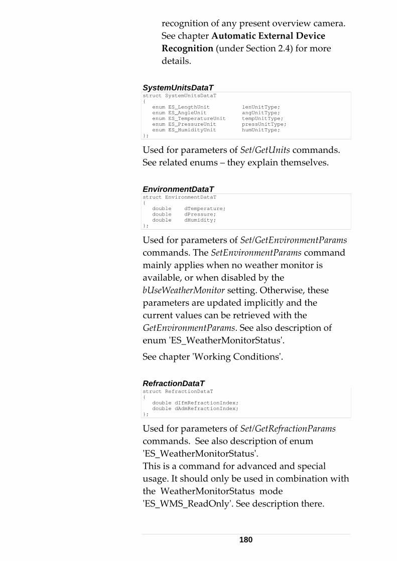
recognition of any present overview camera. See chapter Automatic External Device Recognition (under Section 2.4) for more details.
SystemUnitsDataT struct SystemUnitsDataT { enum ES_LengthUnit lenUnitType; enum ES_AngleUnit angUnitType; enum ES_TemperatureUnit tempUnitType; enum ES_PressureUnit pressUnitType; enum ES_HumidityUnit humUnitType; };
Used for parameters of Set/GetUnits commands. See related enums – they explain themselves. EnvironmentDataT struct EnvironmentDataT { double dTemperature; double dPressure; double dHumidity; };
Used for parameters of Set/GetEnvironmentParams commands. The SetEnvironmentParams command mainly applies when no weather monitor is available, or when disabled by the bUseWeatherMonitor setting. Otherwise, these parameters are updated implicitly and the current values can be retrieved with the GetEnvironmentParams. See also description of enum ʹES_WeatherMonitorStatusʹ.
See chapter ʹWorking Conditionsʹ. RefractionDataT struct RefractionDataT { double dIfmRefractionIndex; double dAdmRefractionIndex; };
Used for parameters of Set/GetRefractionParams commands. See also description of enum ʹES_WeatherMonitorStatusʹ. This is a command for advanced and special usage. It should only be used in combination with the WeatherMonitorStatus mode ʹES_WMS_ReadOnlyʹ. See description there.
180
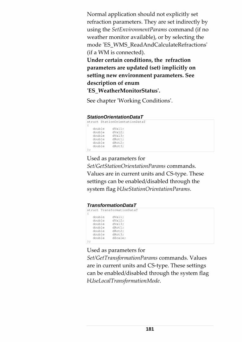
Normal application should not explicitly set refraction parameters. They are set indirectly by using the SetEnvironmentParams command (if no weather monitor available), or by selecting the mode ʹES_WMS_ReadAndCalculateRefractionsʹ (if a WM is connected). Under certain conditions, the refraction parameters are updated (set) implicitly on setting new environment parameters. See description of enum ʹES_WeatherMonitorStatusʹ.
See chapter ʹWorking Conditionsʹ. StationOrientationDataT struct StationOrientationDataT { double dVal1; double dVal2; double dVal3; double dRot1; double dRot2; double dRot3; };
Used as parameters for Set/GetStationOrientationParams commands. Values are in current units and CS‐type. These settings can be enabled/disabled through the system flag bUseStationOrientationParams. TransformationDataT struct TransformationDataT { double dVal1; double dVal2; double dVal3; double dRot1; double dRot2; double dRot3; double dScale; };
Used as parameters for Set/GetTransformationParams commands. Values are in current units and CS‐type. These settings can be enabled/disabled through the system flag bUseLocalTransformationMode.
181
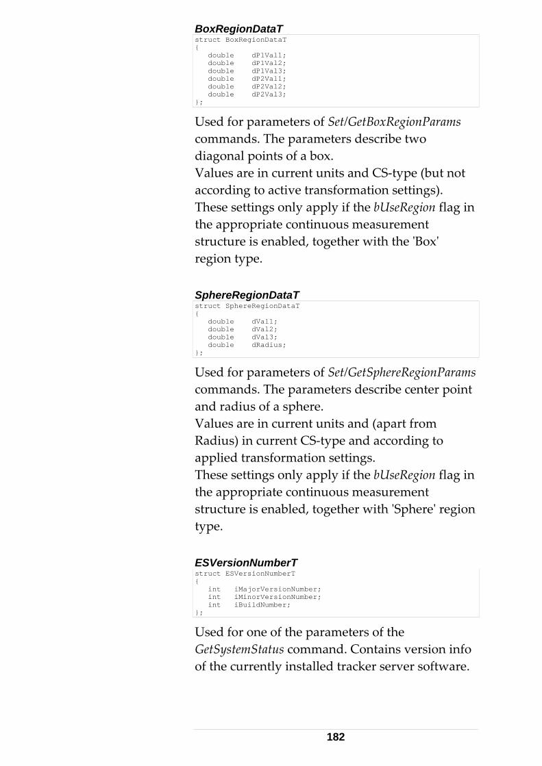
BoxRegionDataT struct BoxRegionDataT { double dP1Val1; double dP1Val2; double dP1Val3; double dP2Val1; double dP2Val2; double dP2Val3; };
Used for parameters of Set/GetBoxRegionParams commands. The parameters describe two diagonal points of a box. Values are in current units and CS‐type (but not according to active transformation settings). These settings only apply if the bUseRegion flag in the appropriate continuous measurement structure is enabled, together with the ʹBoxʹ region type. SphereRegionDataT struct SphereRegionDataT { double dVal1; double dVal2; double dVal3; double dRadius; };
Used for parameters of Set/GetSphereRegionParams commands. The parameters describe center point and radius of a sphere. Values are in current units and (apart from Radius) in current CS‐type and according to applied transformation settings. These settings only apply if the bUseRegion flag in the appropriate continuous measurement structure is enabled, together with ʹSphereʹ region type. ESVersionNumberT struct ESVersionNumberT { int iMajorVersionNumber; int iMinorVersionNumber; int iBuildNumber; };
Used for one of the parameters of the GetSystemStatus command. Contains version info of the currently installed tracker server software.
182
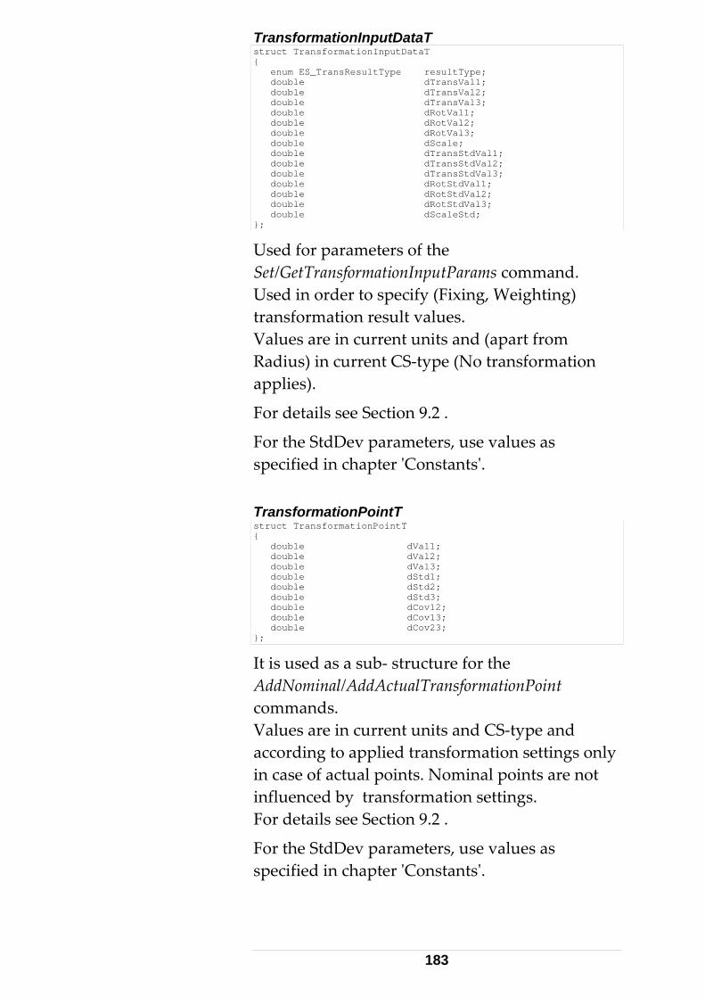
TransformationInputDataT struct TransformationInputDataT { enum ES_TransResultType resultType; double dTransVal1; double dTransVal2; double dTransVal3; double dRotVal1; double dRotVal2; double dRotVal3; double dScale; double dTransStdVal1; double dTransStdVal2; double dTransStdVal3; double dRotStdVal1; double dRotStdVal2; double dRotStdVal3; double dScaleStd; };
Used for parameters of the Set/GetTransformationInputParams command. Used in order to specify (Fixing, Weighting) transformation result values. Values are in current units and (apart from Radius) in current CS‐type (No transformation applies).
For details see Section 9.2 .
For the StdDev parameters, use values as specified in chapter ʹConstantsʹ. TransformationPointT struct TransformationPointT { double dVal1; double dVal2; double dVal3; double dStd1; double dStd2; double dStd3; double dCov12; double dCov13; double dCov23; };
It is used as a sub‐ structure for the AddNominal/AddActualTransformationPoint commands. Values are in current units and CS‐type and according to applied transformation settings only in case of actual points. Nominal points are not influenced by transformation settings. For details see Section 9.2 .
For the StdDev parameters, use values as specified in chapter ʹConstantsʹ.
183
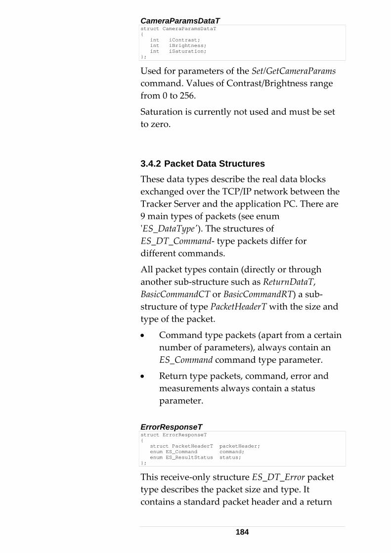
CameraParamsDataT struct CameraParamsDataT { int iContrast; int iBrightness; int iSaturation; };
Used for parameters of the Set/GetCameraParams command. Values of Contrast/Brightness range from 0 to 256.
Saturation is currently not used and must be set to zero. 3.4.2 Packet Data Structures These data types describe the real data blocks exchanged over the TCP/IP network between the Tracker Server and the application PC. There are 9 main types of packets (see enum ʹES_DataTypeʹ). The structures of ES_DT_Command‐ type packets differ for different commands.
All packet types contain (directly or through another sub‐structure such as ReturnDataT, BasicCommandCT or BasicCommandRT) a sub‐structure of type PacketHeaderT with the size and type of the packet.
• Command type packets (apart from a certain number of parameters), always contain an ES_Command command type parameter.
• Return type packets, command, error and measurements always contain a status parameter.
ErrorResponseT struct ErrorResponseT { struct PacketHeaderT packetHeader; enum ES_Command command; enum ES_ResultStatus status; };
This receive‐only structure ES_DT_Error packet type describes the packet size and type. It contains a standard packet header and a return
184
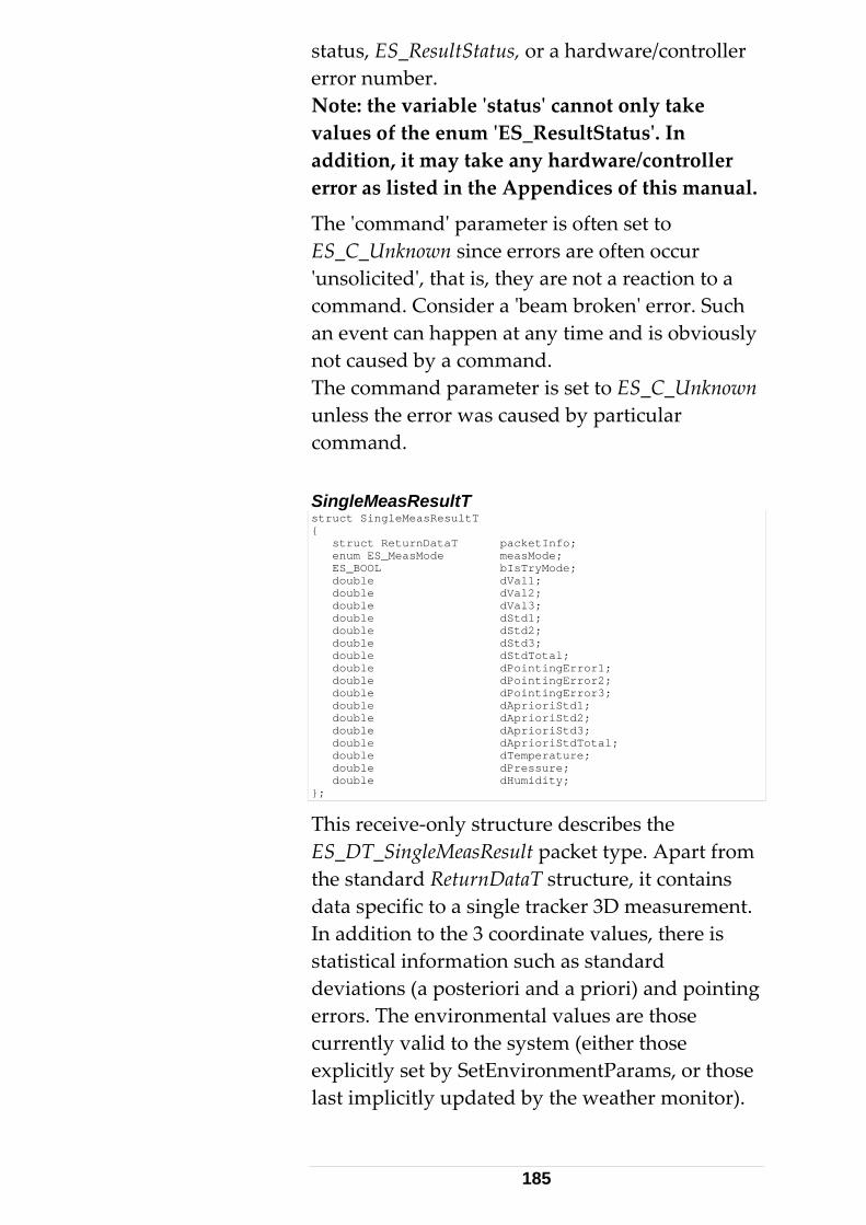
status, ES_ResultStatus, or a hardware/controller error number. Note: the variable ʹstatusʹ cannot only take values of the enum ʹES_ResultStatusʹ. In addition, it may take any hardware/controller error as listed in the Appendices of this manual.
The ʹcommandʹ parameter is often set to ES_C_Unknown since errors are often occur ʹunsolicitedʹ, that is, they are not a reaction to a command. Consider a ʹbeam brokenʹ error. Such an event can happen at any time and is obviously not caused by a command. The command parameter is set to ES_C_Unknown unless the error was caused by particular command. SingleMeasResultT struct SingleMeasResultT { struct ReturnDataT packetInfo; enum ES_MeasMode measMode; ES_BOOL bIsTryMode; double dVal1; double dVal2; double dVal3; double dStd1; double dStd2; double dStd3; double dStdTotal; double dPointingError1; double dPointingError2; double dPointingError3; double dAprioriStd1; double dAprioriStd2; double dAprioriStd3; double dAprioriStdTotal; double dTemperature; double dPressure; double dHumidity; };
This receive‐only structure describes the ES_DT_SingleMeasResult packet type. Apart from the standard ReturnDataT structure, it contains data specific to a single tracker 3D measurement. In addition to the 3 coordinate values, there is statistical information such as standard deviations (a posteriori and a priori) and pointing errors. The environmental values are those currently valid to the system (either those explicitly set by SetEnvironmentParams, or those last implicitly updated by the weather monitor).
185
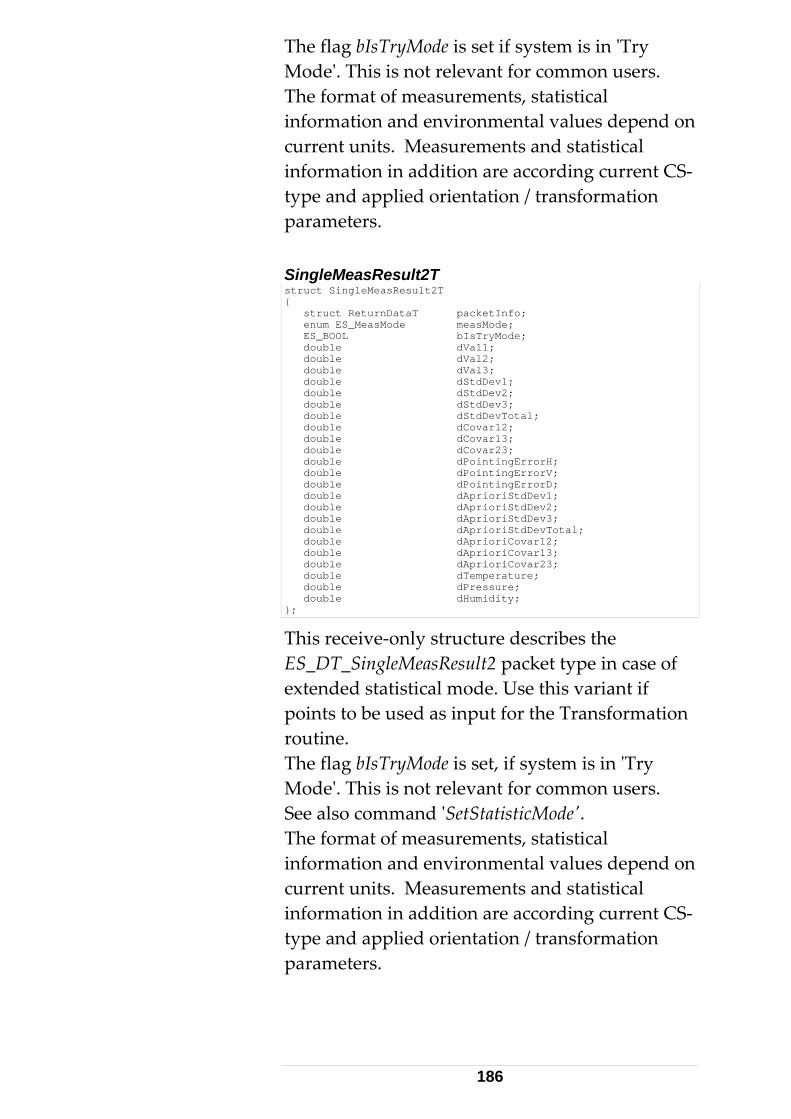
The flag bIsTryMode is set if system is in ʹTry Modeʹ. This is not relevant for common users. The format of measurements, statistical information and environmental values depend on current units. Measurements and statistical information in addition are according current CS‐type and applied orientation / transformation parameters. SingleMeasResult2T struct SingleMeasResult2T { struct ReturnDataT packetInfo; enum ES_MeasMode measMode; ES_BOOL bIsTryMode; double dVal1; double dVal2; double dVal3; double dStdDev1; double dStdDev2; double dStdDev3; double dStdDevTotal; double dCovar12; double dCovar13; double dCovar23; double dPointingErrorH; double dPointingErrorV; double dPointingErrorD; double dAprioriStdDev1; double dAprioriStdDev2; double dAprioriStdDev3; double dAprioriStdDevTotal; double dAprioriCovar12; double dAprioriCovar13; double dAprioriCovar23; double dTemperature; double dPressure; double dHumidity; };
This receive‐only structure describes the ES_DT_SingleMeasResult2 packet type in case of extended statistical mode. Use this variant if points to be used as input for the Transformation routine. The flag bIsTryMode is set, if system is in ʹTry Modeʹ. This is not relevant for common users. See also command ʹSetStatisticModeʹ. The format of measurements, statistical information and environmental values depend on current units. Measurements and statistical information in addition are according current CS‐type and applied orientation / transformation parameters.
186
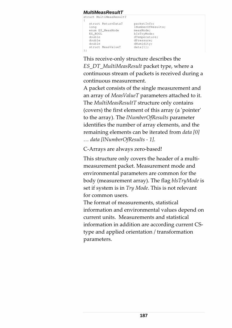
MultiMeasResultT struct MultiMeasResultT { struct ReturnDataT packetInfo; long lNumberOfResults; enum ES_MeasMode measMode; ES_BOOL bIsTryMode; double dTemperature; double dPressure; double dHumidity; struct MeasValueT data[1]; };
This receive‐only structure describes the ES_DT_MultiMeasResult packet type, where a continuous stream of packets is received during a continuous measurement. A packet consists of the single measurement and an array of MeasValueT parameters attached to it. The MultiMeasResultT structure only contains (covers) the first element of this array (a ʹpointerʹ to the array). The lNumberOfResults parameter identifies the number of array elements, and the remaining elements can be iterated from data [0] … data [lNumberOfResults ‐ 1].
C‐Arrays are always zero‐based!
This structure only covers the header of a multi‐measurement packet. Measurement mode and environmental parameters are common for the body (measurement array). The flag bIsTryMode is set if system is in Try Mode. This is not relevant for common users. The format of measurements, statistical information and environmental values depend on current units. Measurements and statistical information in addition are according current CS‐type and applied orientation / transformation parameters.
187
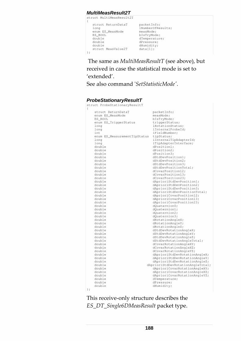
MultiMeasResult2T struct MultiMeasResult2T { struct ReturnDataT packetInfo; long lNumberOfResults; enum ES_MeasMode measMode; ES_BOOL bIsTryMode; double dTemperature; double dPressure; double dHumidity; struct MeasValue2T data[1]; };
The same as MultiMeasResultT (see above), but received in case the statistical mode is set to ‘extended’. See also command ʹSetStatisticModeʹ. ProbeStationaryResultT struct ProbeStationaryResultT { struct ReturnDataT packetInfo; enum ES_MeasMode measMode; ES_BOOL bIsTryMode; enum ES_TriggerStatus triggerStatus; long lRotationStatus; long iInternalProbeId; int iFieldNumber; enum ES_MeasurementTipStatus tipStatus; long iInternalTipAdapterId; long iTipAdapterInterface; double dPosition1; double dPosition2; double dPosition3; double dStdDevPosition1; double dStdDevPosition2; double dStdDevPosition3; double dStdDevPositionTotal; double dCovarPosition12; double dCovarPosition13; double dCovarPosition23; double dAprioriStdDevPosition1; double dAprioriStdDevPosition2; double dAprioriStdDevPosition3; double dAprioriStdDevPositionTotal; double dAprioriCovarPosition12; double dAprioriCovarPosition13; double dAprioriCovarPosition23; double dQuaternion0; double dQuaternion1; double dQuaternion2; double dQuaternion3; double dRotationAngleX; double dRotationAngleY; double dRotationAngleZ; double dStdDevRotationAngleX; double dStdDevRotationAngleY; double dStdDevRotationAngleZ; double dStdDevRotationAngleTotal; double dCovarRotationAngleXY; double dCovarRotationAngleXZ; double dCovarRotationAngleYZ; double dAprioriStdDevRotationAngleX; double dAprioriStdDevRotationAngleY; double dAprioriStdDevRotationAngleZ; double dAprioriStdDevRotationAngleTotal; double dAprioriCovarRotationAngleXY; double dAprioriCovarRotationAngleXZ; double dAprioriCovarRotationAngleYZ; double dTemperature; double dPressure; double dHumidity; };
This receive‐only structure describes the ES_DT_Single6DMeasResult packet type.
188
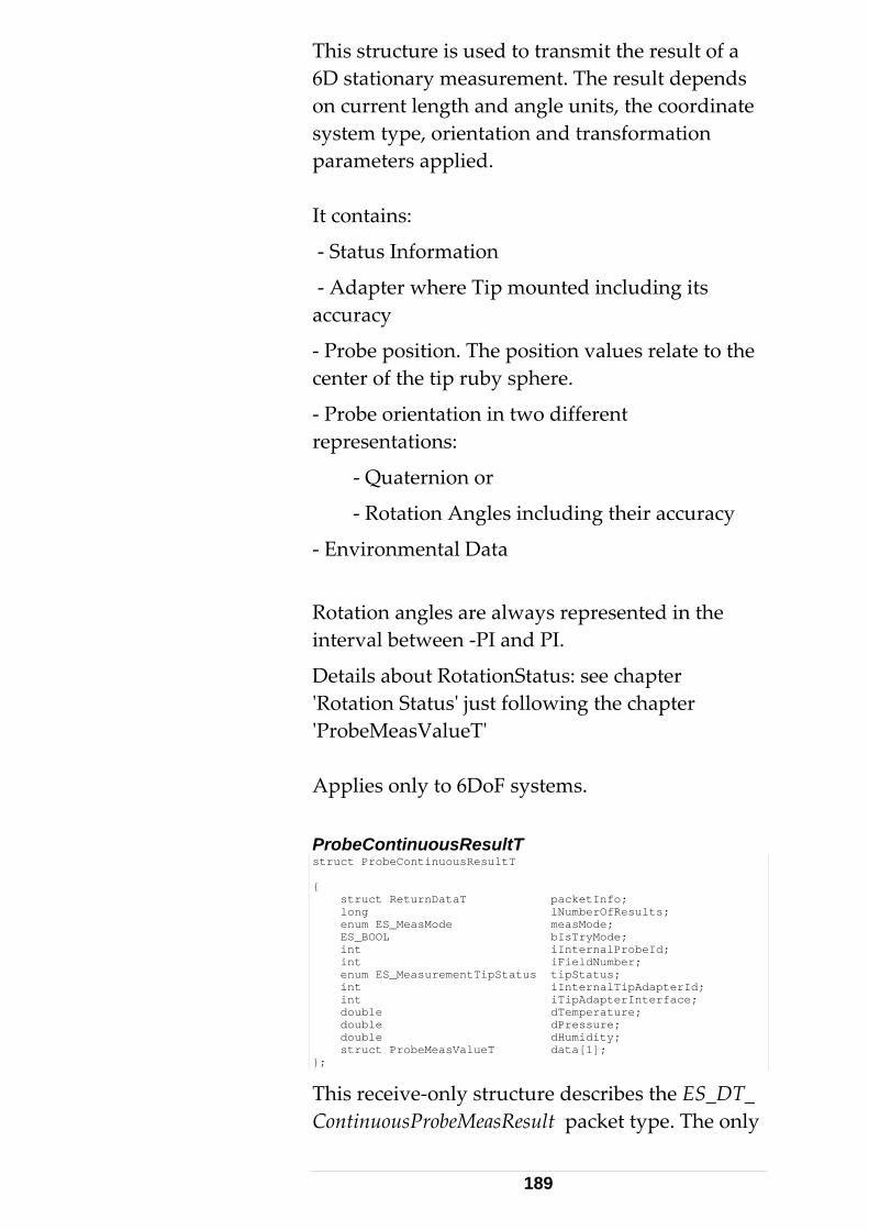
This structure is used to transmit the result of a 6D stationary measurement. The result depends on current length and angle units, the coordinate system type, orientation and transformation parameters applied. It contains:
‐ Status Information
‐ Adapter where Tip mounted including its accuracy
‐ Probe position. The position values relate to the center of the tip ruby sphere.
‐ Probe orientation in two different representations:
‐ Quaternion or
‐ Rotation Angles including their accuracy
‐ Environmental Data
Rotation angles are always represented in the interval between ‐PI and PI.
Details about RotationStatus: see chapter ʹRotation Statusʹ just following the chapter ʹProbeMeasValueTʹ Applies only to 6DoF systems. ProbeContinuousResultT struct ProbeContinuousResultT { struct ReturnDataT packetInfo; long lNumberOfResults; enum ES_MeasMode measMode; ES_BOOL bIsTryMode; int iInternalProbeId; int iFieldNumber; enum ES_MeasurementTipStatus tipStatus; int iInternalTipAdapterId; int iTipAdapterInterface; double dTemperature; double dPressure; double dHumidity; struct ProbeMeasValueT data[1]; };
This receive‐only structure describes the ES_DT_ ContinuousProbeMeasResult packet type. The only
189
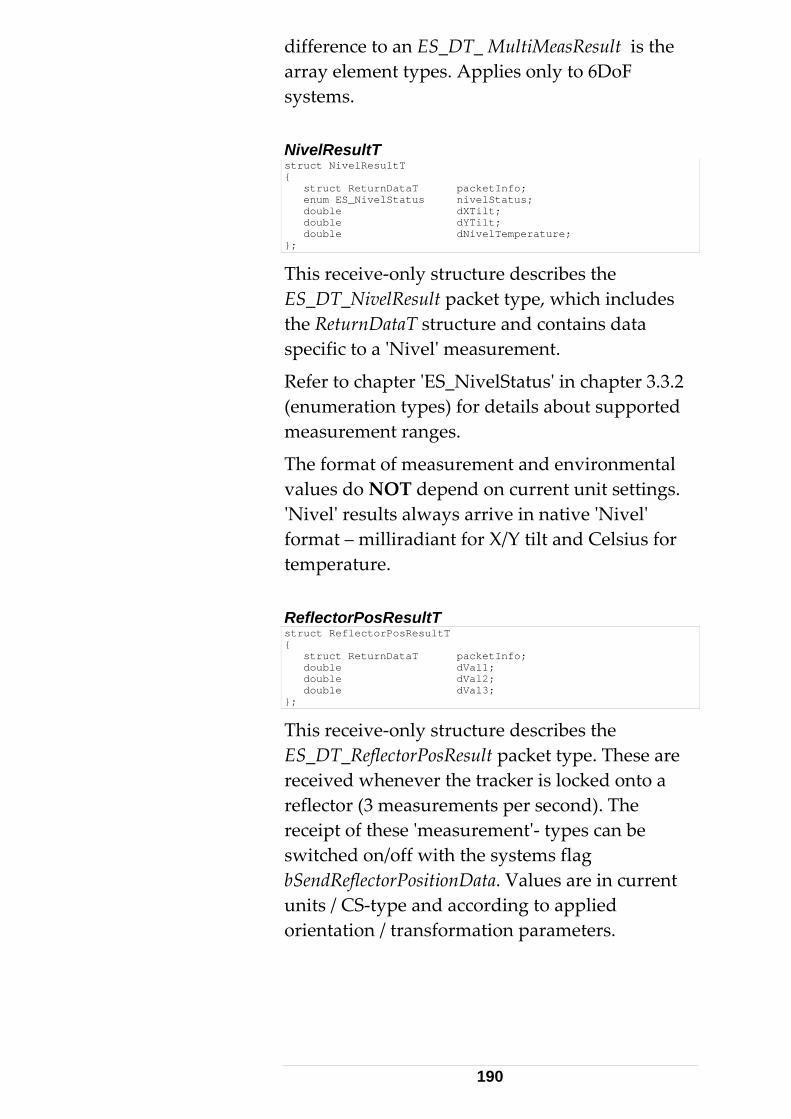
difference to an ES_DT_ MultiMeasResult is the array element types. Applies only to 6DoF systems. NivelResultT struct NivelResultT { struct ReturnDataT packetInfo; enum ES_NivelStatus nivelStatus; double dXTilt; double dYTilt; double dNivelTemperature; };
This receive‐only structure describes the ES_DT_NivelResult packet type, which includes the ReturnDataT structure and contains data specific to a ʹNivelʹ measurement.
Refer to chapter ʹES_NivelStatusʹ in chapter 3.3.2 (enumeration types) for details about supported measurement ranges.
The format of measurement and environmental values do NOT depend on current unit settings. ʹNivelʹ results always arrive in native ʹNivelʹ format – milliradiant for X/Y tilt and Celsius for temperature. ReflectorPosResultT struct ReflectorPosResultT { struct ReturnDataT packetInfo; double dVal1; double dVal2; double dVal3; };
This receive‐only structure describes the ES_DT_ReflectorPosResult packet type. These are received whenever the tracker is locked onto a reflector (3 measurements per second). The receipt of these ʹmeasurementʹ‐ types can be switched on/off with the systems flag bSendReflectorPositionData. Values are in current units / CS‐type and according to applied orientation / transformation parameters.
190
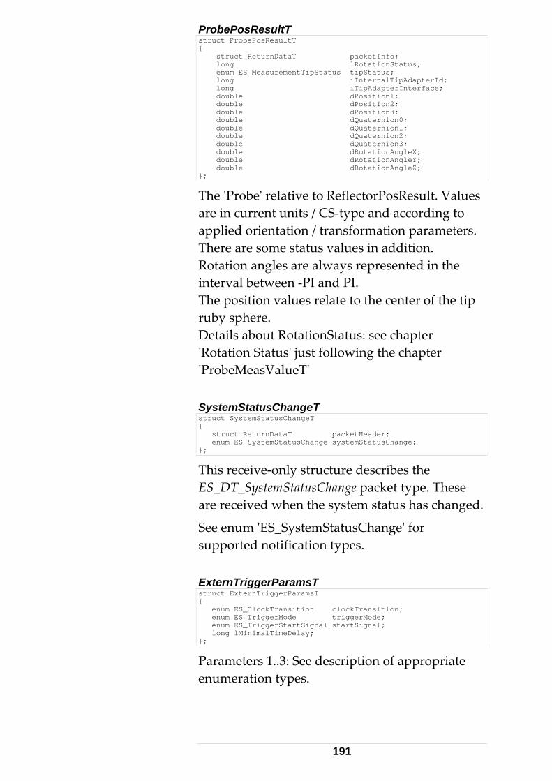
ProbePosResultT struct ProbePosResultT { struct ReturnDataT packetInfo; long lRotationStatus; enum ES_MeasurementTipStatus tipStatus; long iInternalTipAdapterId; long iTipAdapterInterface; double dPosition1; double dPosition2; double dPosition3; double dQuaternion0; double dQuaternion1; double dQuaternion2; double dQuaternion3; double dRotationAngleX; double dRotationAngleY; double dRotationAngleZ; };
The ʹProbeʹ relative to ReflectorPosResult. Values are in current units / CS‐type and according to applied orientation / transformation parameters. There are some status values in addition. Rotation angles are always represented in the interval between ‐PI and PI. The position values relate to the center of the tip ruby sphere. Details about RotationStatus: see chapter ʹRotation Statusʹ just following the chapter ʹProbeMeasValueTʹ SystemStatusChangeT struct SystemStatusChangeT { struct ReturnDataT packetHeader; enum ES_SystemStatusChange systemStatusChange; };
This receive‐only structure describes the ES_DT_SystemStatusChange packet type. These are received when the system status has changed.
See enum ʹES_SystemStatusChangeʹ for supported notification types. ExternTriggerParamsT struct ExternTriggerParamsT { enum ES_ClockTransition clockTransition; enum ES_TriggerMode triggerMode; enum ES_TriggerStartSignal startSignal; long lMinimalTimeDelay; };
Parameters 1..3: See description of appropriate enumeration types.
191
lMinimalTimeDelay: The time delay between trigger event and measurement. Non- Parameter Command/Return Types
Lists all non‐ parameter command structures. They are derived from the BasicCommandCT (command‐types; client to Server) and the BasicCommandRT (return‐types; Server to client).
192
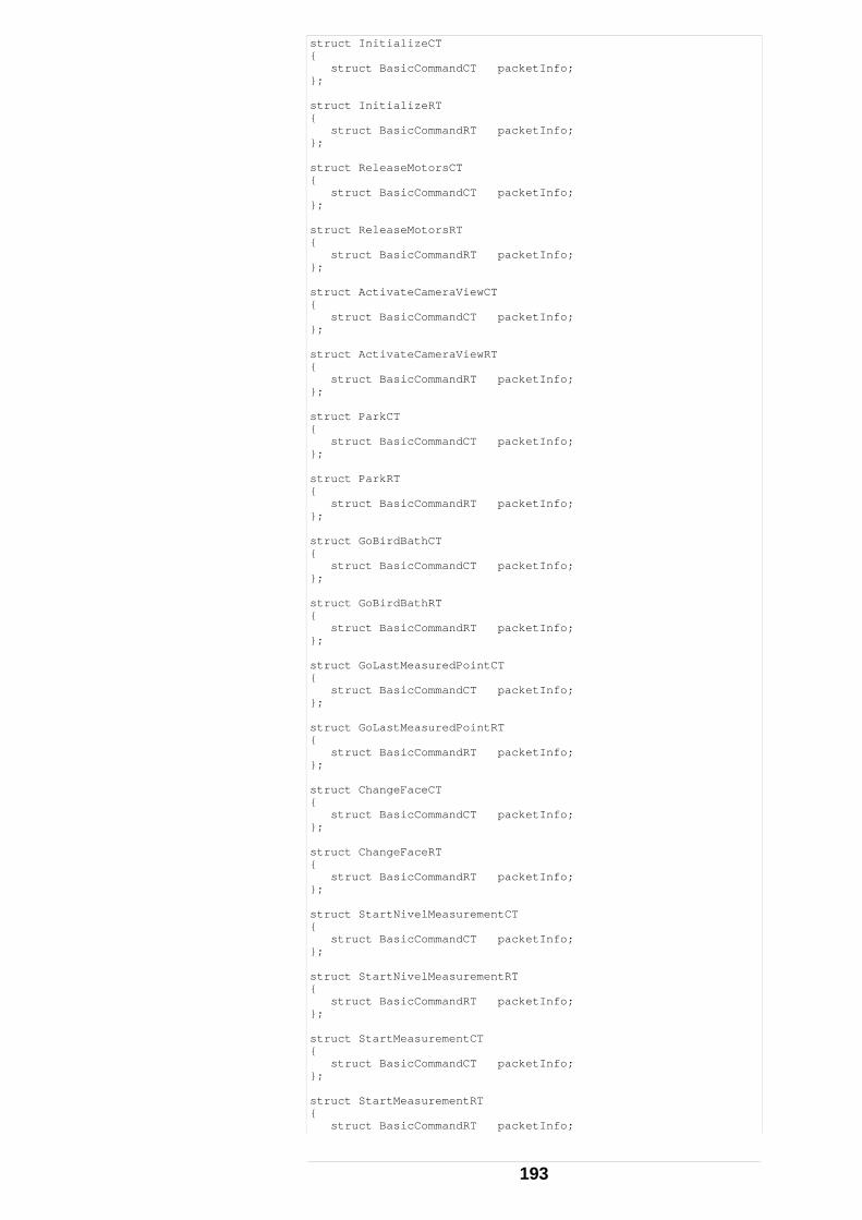
struct InitializeCT { struct BasicCommandCT packetInfo; }; struct InitializeRT { struct BasicCommandRT packetInfo; }; struct ReleaseMotorsCT { struct BasicCommandCT packetInfo; }; struct ReleaseMotorsRT { struct BasicCommandRT packetInfo; }; struct ActivateCameraViewCT { struct BasicCommandCT packetInfo; }; struct ActivateCameraViewRT { struct BasicCommandRT packetInfo; }; struct ParkCT { struct BasicCommandCT packetInfo; }; struct ParkRT { struct BasicCommandRT packetInfo; }; struct GoBirdBathCT { struct BasicCommandCT packetInfo; }; struct GoBirdBathRT { struct BasicCommandRT packetInfo; }; struct GoLastMeasuredPointCT { struct BasicCommandCT packetInfo; }; struct GoLastMeasuredPointRT { struct BasicCommandRT packetInfo; }; struct ChangeFaceCT { struct BasicCommandCT packetInfo; }; struct ChangeFaceRT { struct BasicCommandRT packetInfo; }; struct StartNivelMeasurementCT { struct BasicCommandCT packetInfo; }; struct StartNivelMeasurementRT { struct BasicCommandRT packetInfo; }; struct StartMeasurementCT { struct BasicCommandCT packetInfo; }; struct StartMeasurementRT { struct BasicCommandRT packetInfo;
193
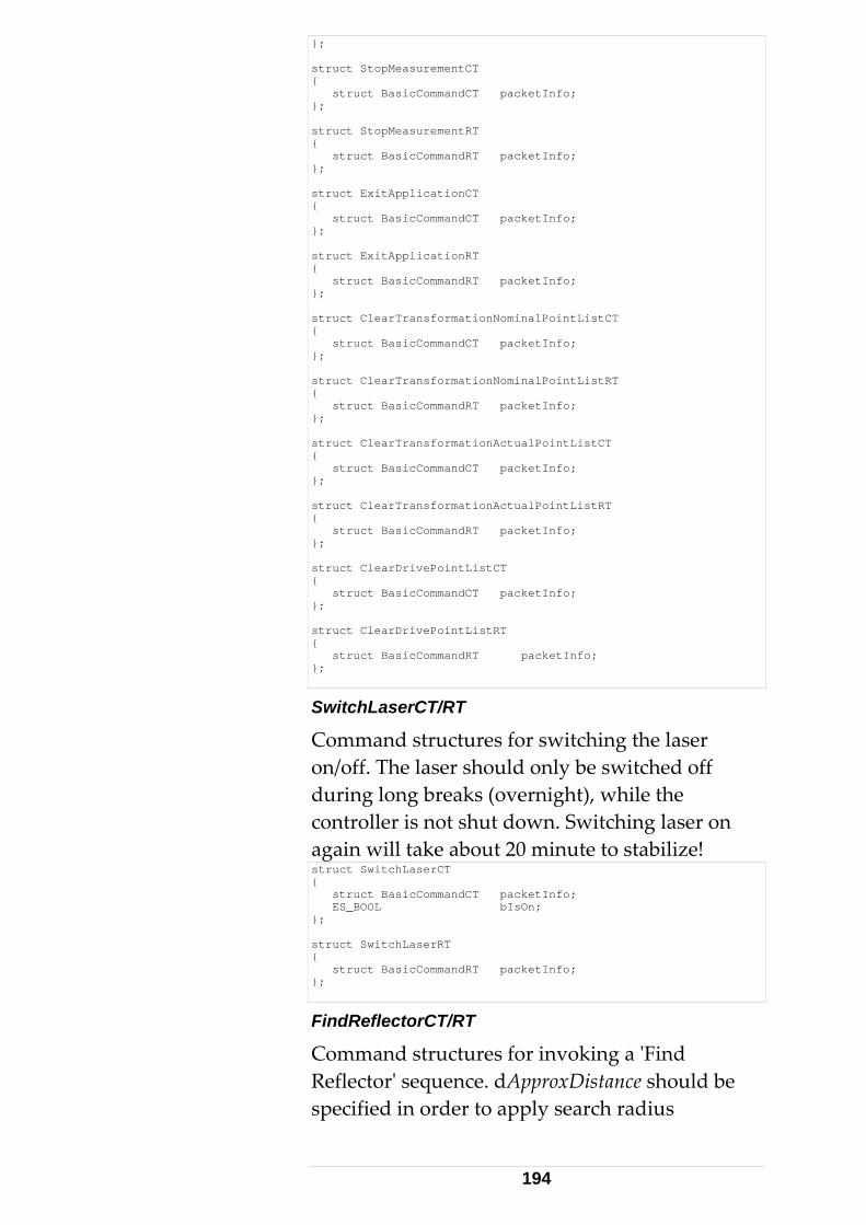
}; struct StopMeasurementCT { struct BasicCommandCT packetInfo; }; struct StopMeasurementRT { struct BasicCommandRT packetInfo; }; struct ExitApplicationCT { struct BasicCommandCT packetInfo; }; struct ExitApplicationRT { struct BasicCommandRT packetInfo; }; struct ClearTransformationNominalPointListCT { struct BasicCommandCT packetInfo; }; struct ClearTransformationNominalPointListRT { struct BasicCommandRT packetInfo; }; struct ClearTransformationActualPointListCT { struct BasicCommandCT packetInfo; }; struct ClearTransformationActualPointListRT { struct BasicCommandRT packetInfo; }; struct ClearDrivePointListCT { struct BasicCommandCT packetInfo; }; struct ClearDrivePointListRT { struct BasicCommandRT packetInfo; };
SwitchLaserCT/RT
Command structures for switching the laser on/off. The laser should only be switched off during long breaks (overnight), while the controller is not shut down. Switching laser on again will take about 20 minute to stabilize! struct SwitchLaserCT { struct BasicCommandCT packetInfo; ES_BOOL bIsOn; }; struct SwitchLaserRT { struct BasicCommandRT packetInfo; };
FindReflectorCT/RT
Command structures for invoking a ʹFind Reflectorʹ sequence. dApproxDistance should be specified in order to apply search radius
194
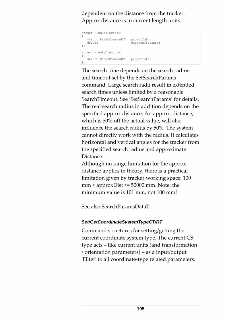
dependent on the distance from the tracker. Approx distance is in current length units. struct FindReflectorCT { struct BasicCommandCT packetInfo; double dApproxDistance; }; struct FindReflectorRT { struct BasicCommandRT packetInfo; };
The search time depends on the search radius and timeout set by the SetSearchParams command. Large search radii result in extended search times unless limited by a reasonable SearchTimeout. See ‘SetSearchParams’ for details. The real search radius in addition depends on the specified approx distance. An approx. distance, which is 50% off the actual value, will also influence the search radius by 50%. The system cannot directly work with the radius. It calculates horizontal and vertical angles for the tracker from the specified search radius and approximate Distance. Although no range limitation for the approx distance applies in theory, there is a practical limitation given by tracker working space: 100 mm < approxDist <= 50000 mm. Note: the minimum value is 101 mm, not 100 mm! See also SearchParamsDataT. Set/GetCoordinateSystemTypeCT/RT
Command structures for setting/getting the current coordinate system type. The current CS‐type acts – like current units (and transformation / orientation parameters) – as a input/output ʹFilterʹ to all coordinate‐type related parameters.
195
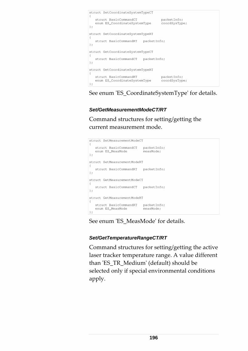
struct SetCoordinateSystemTypeCT { struct BasicCommandCT packetInfo; enum ES_CoordinateSystemType coordSysType; }; struct SetCoordinateSystemTypeRT { struct BasicCommandRT packetInfo; }; struct GetCoordinateSystemTypeCT { struct BasicCommandCT packetInfo; }; struct GetCoordinateSystemTypeRT { struct BasicCommandRT packetInfo; enum ES_CoordinateSystemType coordSysType; };
See enum ʹES_CoordinateSystemTypeʹ for details. Set/GetMeasurementModeCT/RT
Command structures for setting/getting the current measurement mode. struct SetMeasurementModeCT { struct BasicCommandCT packetInfo; enum ES_MeasMode measMode; }; struct SetMeasurementModeRT { struct BasicCommandRT packetInfo; }; struct GetMeasurementModeCT { struct BasicCommandCT packetInfo; }; struct GetMeasurementModeRT { struct BasicCommandRT packetInfo; enum ES_MeasMode measMode; };
See enum ʹES_MeasModeʹ for details. Set/GetTemperatureRangeCT/RT
Command structures for setting/getting the active laser tracker temperature range. A value different than ʹES_TR_Mediumʹ (default) should be selected only if special environmental conditions apply.
196
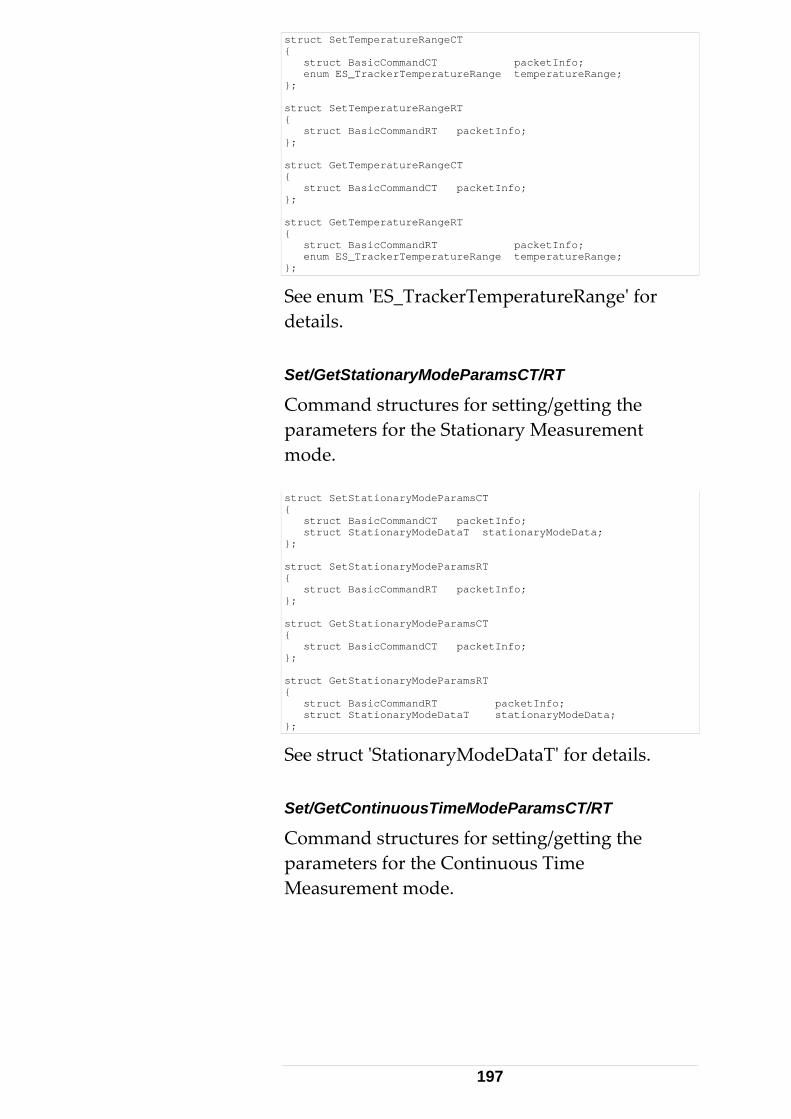
struct SetTemperatureRangeCT { struct BasicCommandCT packetInfo; enum ES_TrackerTemperatureRange temperatureRange; }; struct SetTemperatureRangeRT { struct BasicCommandRT packetInfo; }; struct GetTemperatureRangeCT { struct BasicCommandCT packetInfo; }; struct GetTemperatureRangeRT { struct BasicCommandRT packetInfo; enum ES_TrackerTemperatureRange temperatureRange; };
See enum ʹES_TrackerTemperatureRangeʹ for details. Set/GetStationaryModeParamsCT/RT
Command structures for setting/getting the parameters for the Stationary Measurement mode. struct SetStationaryModeParamsCT { struct BasicCommandCT packetInfo; struct StationaryModeDataT stationaryModeData; }; struct SetStationaryModeParamsRT { struct BasicCommandRT packetInfo; }; struct GetStationaryModeParamsCT { struct BasicCommandCT packetInfo; }; struct GetStationaryModeParamsRT { struct BasicCommandRT packetInfo; struct StationaryModeDataT stationaryModeData; };
See struct ʹStationaryModeDataTʹ for details. Set/GetContinuousTimeModeParamsCT/RT
Command structures for setting/getting the parameters for the Continuous Time Measurement mode.
197
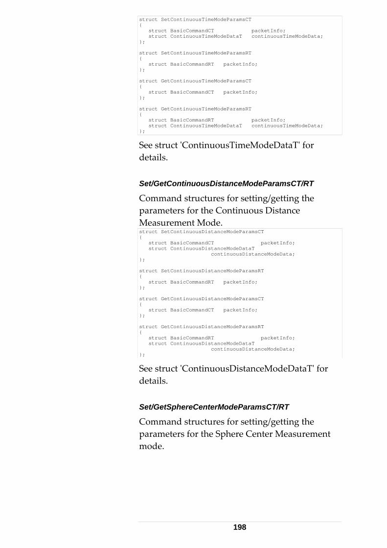
struct SetContinuousTimeModeParamsCT { struct BasicCommandCT packetInfo; struct ContinuousTimeModeDataT continuousTimeModeData; }; struct SetContinuousTimeModeParamsRT { struct BasicCommandRT packetInfo; }; struct GetContinuousTimeModeParamsCT { struct BasicCommandCT packetInfo; }; struct GetContinuousTimeModeParamsRT { struct BasicCommandRT packetInfo; struct ContinuousTimeModeDataT continuousTimeModeData; };
See struct ʹContinuousTimeModeDataTʹ for details. Set/GetContinuousDistanceModeParamsCT/RT
Command structures for setting/getting the parameters for the Continuous Distance Measurement Mode. struct SetContinuousDistanceModeParamsCT { struct BasicCommandCT packetInfo; struct ContinuousDistanceModeDataT continuousDistanceModeData; }; struct SetContinuousDistanceModeParamsRT { struct BasicCommandRT packetInfo; }; struct GetContinuousDistanceModeParamsCT { struct BasicCommandCT packetInfo; }; struct GetContinuousDistanceModeParamsRT { struct BasicCommandRT packetInfo; struct ContinuousDistanceModeDataT continuousDistanceModeData; };
See struct ʹContinuousDistanceModeDataTʹ for details. Set/GetSphereCenterModeParamsCT/RT
Command structures for setting/getting the parameters for the Sphere Center Measurement mode.
198
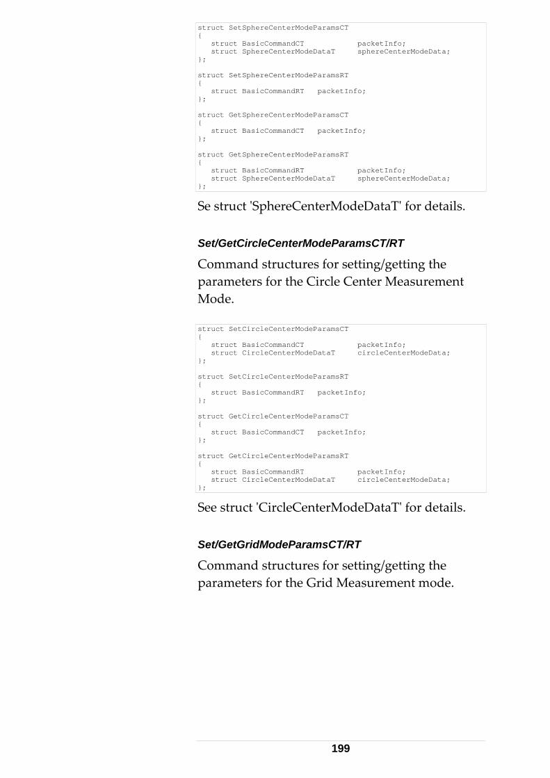
struct SetSphereCenterModeParamsCT { struct BasicCommandCT packetInfo; struct SphereCenterModeDataT sphereCenterModeData; }; struct SetSphereCenterModeParamsRT { struct BasicCommandRT packetInfo; }; struct GetSphereCenterModeParamsCT { struct BasicCommandCT packetInfo; }; struct GetSphereCenterModeParamsRT { struct BasicCommandRT packetInfo; struct SphereCenterModeDataT sphereCenterModeData; };
Se struct ʹSphereCenterModeDataTʹ for details. Set/GetCircleCenterModeParamsCT/RT
Command structures for setting/getting the parameters for the Circle Center Measurement Mode. struct SetCircleCenterModeParamsCT { struct BasicCommandCT packetInfo; struct CircleCenterModeDataT circleCenterModeData; }; struct SetCircleCenterModeParamsRT { struct BasicCommandRT packetInfo; }; struct GetCircleCenterModeParamsCT { struct BasicCommandCT packetInfo; }; struct GetCircleCenterModeParamsRT { struct BasicCommandRT packetInfo; struct CircleCenterModeDataT circleCenterModeData; };
See struct ʹCircleCenterModeDataTʹ for details. Set/GetGridModeParamsCT/RT
Command structures for setting/getting the parameters for the Grid Measurement mode.
199
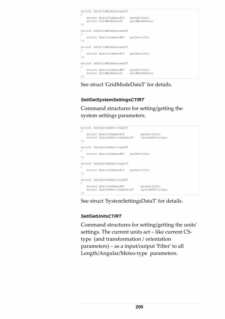
struct SetGridModeParamsCT { struct BasicCommandCT packetInfo; struct GridModeDataT gridModeData; }; struct SetGridModeParamsRT { struct BasicCommandRT packetInfo; }; struct GetGridModeParamsCT { struct BasicCommandCT packetInfo; }; struct GetGridModeParamsRT { struct BasicCommandRT packetInfo; struct GridModeDataT gridModeData; };
See struct ʹGridModeDataTʹ for details. Set/GetSystemSettingsCT/RT
Command structures for setting/getting the system settings parameters. struct SetSystemSettingsCT { struct BasicCommandCT packetInfo; struct SystemSettingsDataT systemSettings; }; struct SetSystemSettingsRT { struct BasicCommandRT packetInfo; }; struct GetSystemSettingsCT { struct BasicCommandCT packetInfo; }; struct GetSystemSettingsRT { struct BasicCommandRT packetInfo; struct SystemSettingsDataT systemSettings; };
See struct ʹSystemSettingsDataTʹ for details. Set/GetUnitsCT/RT
Command structures for setting/getting the unitsʹ settings. The current units act – like current CS‐type (and transformation / orientation parameters) – as a input/output ʹFilterʹ to all Length/Angular/Meteo‐type parameters.
200
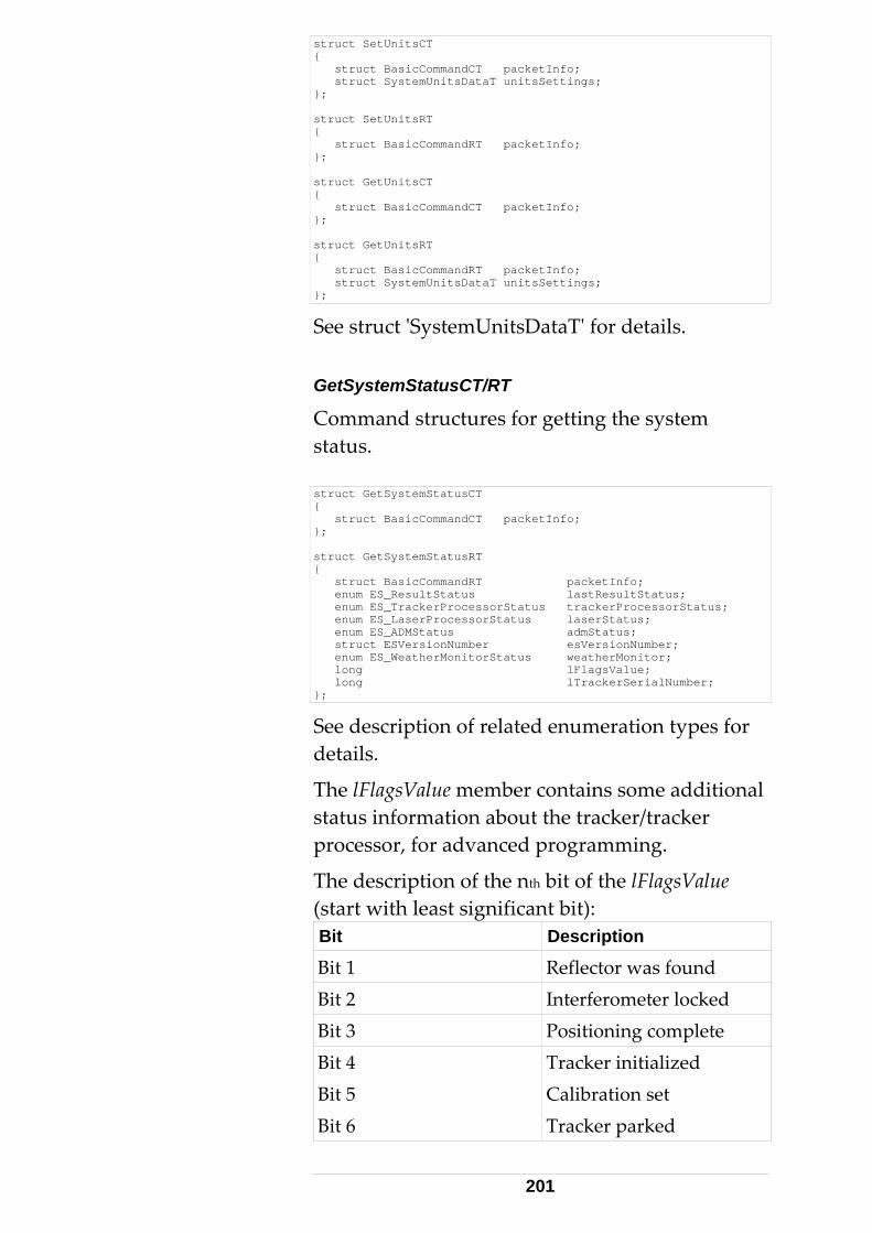
struct SetUnitsCT { struct BasicCommandCT packetInfo; struct SystemUnitsDataT unitsSettings; }; struct SetUnitsRT { struct BasicCommandRT packetInfo; }; struct GetUnitsCT { struct BasicCommandCT packetInfo; }; struct GetUnitsRT { struct BasicCommandRT packetInfo; struct SystemUnitsDataT unitsSettings; };
See struct ʹSystemUnitsDataTʹ for details. GetSystemStatusCT/RT
Command structures for getting the system status. struct GetSystemStatusCT { struct BasicCommandCT packetInfo; }; struct GetSystemStatusRT { struct BasicCommandRT packetInfo; enum ES_ResultStatus lastResultStatus; enum ES_TrackerProcessorStatus trackerProcessorStatus; enum ES_LaserProcessorStatus laserStatus; enum ES_ADMStatus admStatus; struct ESVersionNumber esVersionNumber; enum ES_WeatherMonitorStatus weatherMonitor; long lFlagsValue; long lTrackerSerialNumber; };
See description of related enumeration types for details.
The lFlagsValue member contains some additional status information about the tracker/tracker processor, for advanced programming.
The description of the nth bit of the lFlagsValue (start with least significant bit): Bit Description
Bit 1 Reflector was found Bit 2 Interferometer locked Bit 3 Positioning complete Bit 4 Tracker initialized Bit 5 Calibration set Bit 6 Tracker parked
201
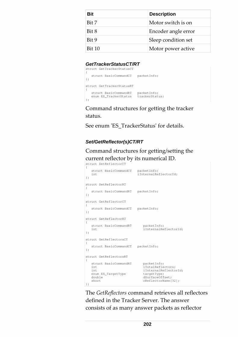
Bit Description
Bit 7 Motor switch is on Bit 8 Encoder angle error Bit 9 Sleep condition set Bit 10 Motor power active GetTrackerStatusCT/RT struct GetTrackerStatusCT { struct BasicCommandCT packetInfo; }; struct GetTrackerStatusRT { struct BasicCommandRT packetInfo; enum ES_TrackerStatus trackerStatus; };
Command structures for getting the tracker status.
See enum ʹES_TrackerStatusʹ for details. Set/GetReflector(s)CT/RT
Command structures for getting/setting the current reflector by its numerical ID. struct SetReflectorCT { struct BasicCommandCT packetInfo; int iInternalReflectorId; }; struct SetReflectorRT { struct BasicCommandRT packetInfo; }; struct GetReflectorCT { struct BasicCommandCT packetInfo; }; struct GetReflectorRT { struct BasicCommandRT packetInfo; int iInternalReflectorId; }; struct GetReflectorsCT { struct BasicCommandCT packetInfo; }; struct GetReflectorsRT { struct BasicCommandRT packetInfo; int iTotalReflectors; int iInternalReflectorId; enum ES_TargetType targetType; double dSurfaceOffset; short cReflectorName[32]; };
The GetReflectors command retrieves all reflectors defined in the Tracker Server. The answer consists of as many answer packets as reflector
202
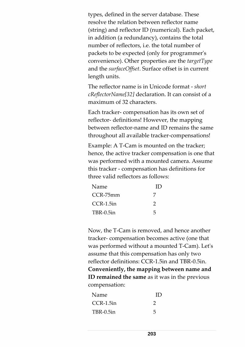
types, defined in the server database. These resolve the relation between reflector name (string) and reflector ID (numerical). Each packet, in addition (a redundancy), contains the total number of reflectors, i.e. the total number of packets to be expected (only for programmerʹs convenience). Other properties are the targetType and the surfaceOffset. Surface offset is in current length units.
The reflector name is in Unicode format ‐ short cReflectorName[32] declaration. It can consist of a maximum of 32 characters.
Each tracker‐ compensation has its own set of reflector‐ definitions! However, the mapping between reflector‐name and ID remains the same throughout all available tracker‐compensations!
Example: A T‐Cam is mounted on the tracker; hence, the active tracker compensation is one that was performed with a mounted camera. Assume this tracker ‐ compensation has definitions for three valid reflectors as follows:
Name ID CCR‐75mm 7 CCR‐1.5in 2 TBR‐0.5in 5
Now, the T‐Cam is removed, and hence another tracker‐ compensation becomes active (one that was performed without a mounted T‐Cam). Letʹs assume that this compensation has only two reflector definitions: CCR‐1.5in and TBR‐0.5in. Conveniently, the mapping between name and ID remained the same as it was in the previous compensation:
Name ID CCR‐1.5in 2 TBR‐0.5in 5
203
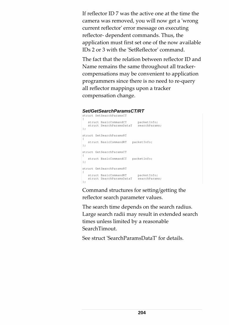
If reflector ID 7 was the active one at the time the camera was removed, you will now get a ʹwrong current reflectorʹ error message on executing reflector‐ dependent commands. Thus, the application must first set one of the now available IDs 2 or 3 with the ʹSetReflectorʹ command.
The fact that the relation between reflector ID and Name remains the same throughout all tracker‐ compensations may be convenient to application programmers since there is no need to re‐query all reflector mappings upon a tracker compensation change. Set/GetSearchParamsCT/RT struct SetSearchParamsCT { struct BasicCommandCT packetInfo; struct SearchParamsDataT searchParams; }; struct SetSearchParamsRT { struct BasicCommandRT packetInfo; }; struct GetSearchParamsCT { struct BasicCommandCT packetInfo; }; struct GetSearchParamsRT { struct BasicCommandRT packetInfo; struct SearchParamsDataT searchParams; };
Command structures for setting/getting the reflector search parameter values.
The search time depends on the search radius. Large search radii may result in extended search times unless limited by a reasonable SearchTimout.
See struct ʹSearchParamsDataTʹ for details.
204
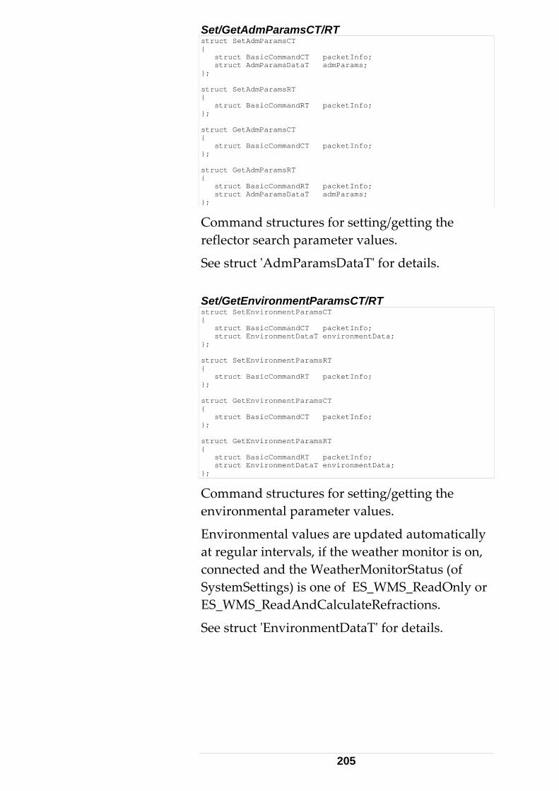
Set/GetAdmParamsCT/RT struct SetAdmParamsCT { struct BasicCommandCT packetInfo; struct AdmParamsDataT admParams; }; struct SetAdmParamsRT { struct BasicCommandRT packetInfo; }; struct GetAdmParamsCT { struct BasicCommandCT packetInfo; }; struct GetAdmParamsRT { struct BasicCommandRT packetInfo; struct AdmParamsDataT admParams; };
Command structures for setting/getting the reflector search parameter values.
See struct ʹAdmParamsDataTʹ for details. Set/GetEnvironmentParamsCT/RT struct SetEnvironmentParamsCT { struct BasicCommandCT packetInfo; struct EnvironmentDataT environmentData; }; struct SetEnvironmentParamsRT { struct BasicCommandRT packetInfo; }; struct GetEnvironmentParamsCT { struct BasicCommandCT packetInfo; }; struct GetEnvironmentParamsRT { struct BasicCommandRT packetInfo; struct EnvironmentDataT environmentData; };
Command structures for setting/getting the environmental parameter values.
Environmental values are updated automatically at regular intervals, if the weather monitor is on, connected and the WeatherMonitorStatus (of SystemSettings) is one of ES_WMS_ReadOnly or ES_WMS_ReadAndCalculateRefractions.
See struct ʹEnvironmentDataTʹ for details.
205
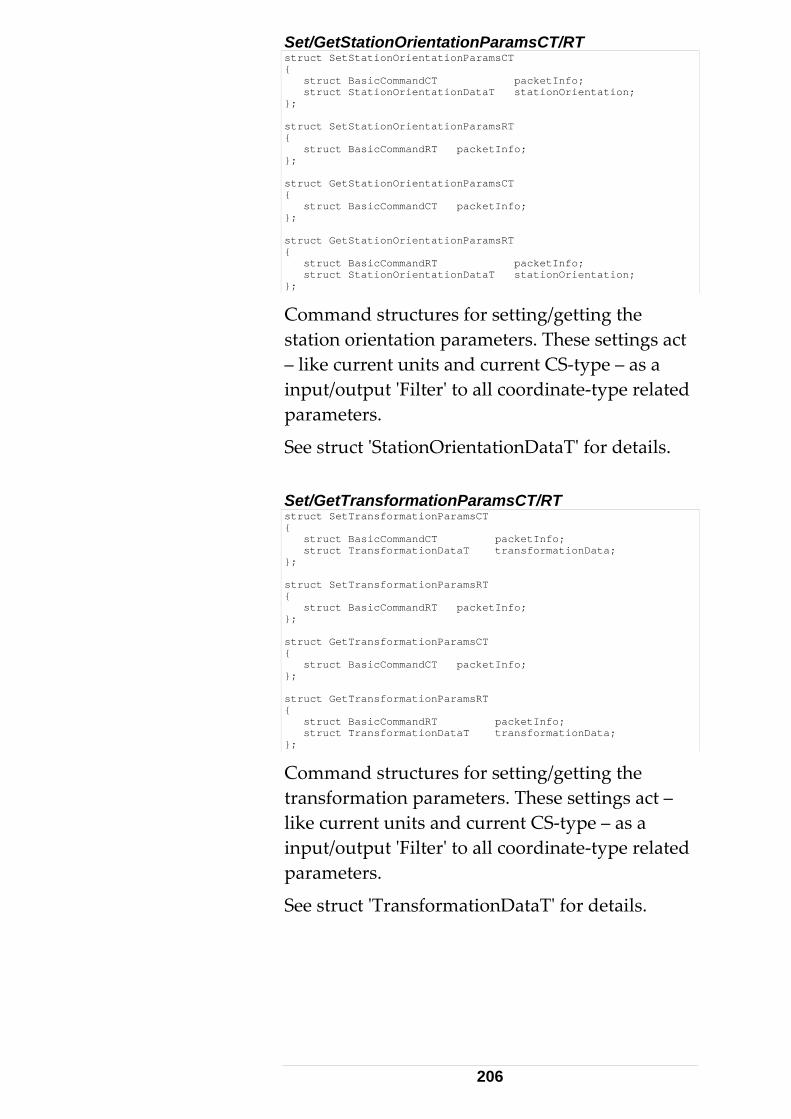
Set/GetStationOrientationParamsCT/RT struct SetStationOrientationParamsCT { struct BasicCommandCT packetInfo; struct StationOrientationDataT stationOrientation; }; struct SetStationOrientationParamsRT { struct BasicCommandRT packetInfo; }; struct GetStationOrientationParamsCT { struct BasicCommandCT packetInfo; }; struct GetStationOrientationParamsRT { struct BasicCommandRT packetInfo; struct StationOrientationDataT stationOrientation; };
Command structures for setting/getting the station orientation parameters. These settings act – like current units and current CS‐type – as a input/output ʹFilterʹ to all coordinate‐type related parameters.
See struct ʹStationOrientationDataTʹ for details. Set/GetTransformationParamsCT/RT struct SetTransformationParamsCT { struct BasicCommandCT packetInfo; struct TransformationDataT transformationData; }; struct SetTransformationParamsRT { struct BasicCommandRT packetInfo; }; struct GetTransformationParamsCT { struct BasicCommandCT packetInfo; }; struct GetTransformationParamsRT { struct BasicCommandRT packetInfo; struct TransformationDataT transformationData; };
Command structures for setting/getting the transformation parameters. These settings act – like current units and current CS‐type – as a input/output ʹFilterʹ to all coordinate‐type related parameters.
See struct ʹTransformationDataTʹ for details.
206
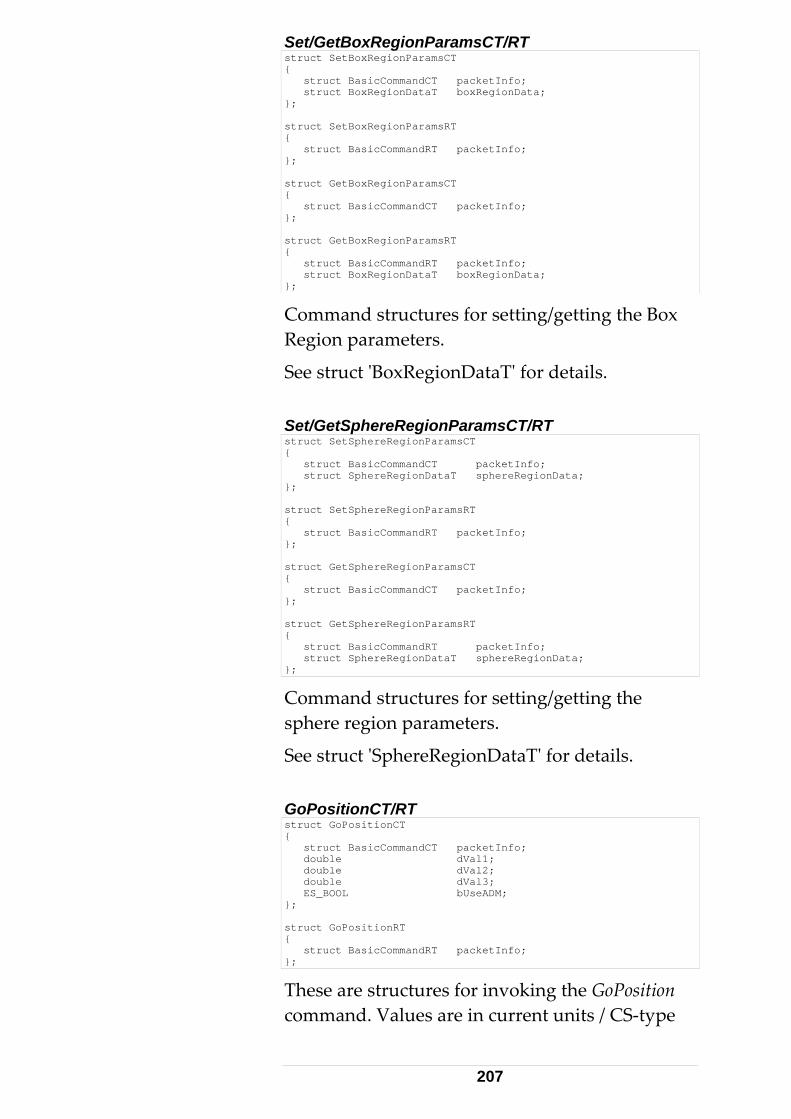
Set/GetBoxRegionParamsCT/RT struct SetBoxRegionParamsCT { struct BasicCommandCT packetInfo; struct BoxRegionDataT boxRegionData; }; struct SetBoxRegionParamsRT { struct BasicCommandRT packetInfo; }; struct GetBoxRegionParamsCT { struct BasicCommandCT packetInfo; }; struct GetBoxRegionParamsRT { struct BasicCommandRT packetInfo; struct BoxRegionDataT boxRegionData; };
Command structures for setting/getting the Box Region parameters.
See struct ʹBoxRegionDataTʹ for details. Set/GetSphereRegionParamsCT/RT struct SetSphereRegionParamsCT { struct BasicCommandCT packetInfo; struct SphereRegionDataT sphereRegionData; }; struct SetSphereRegionParamsRT { struct BasicCommandRT packetInfo; }; struct GetSphereRegionParamsCT { struct BasicCommandCT packetInfo; }; struct GetSphereRegionParamsRT { struct BasicCommandRT packetInfo; struct SphereRegionDataT sphereRegionData; };
Command structures for setting/getting the sphere region parameters.
See struct ʹSphereRegionDataTʹ for details. GoPositionCT/RT struct GoPositionCT { struct BasicCommandCT packetInfo; double dVal1; double dVal2; double dVal3; ES_BOOL bUseADM; }; struct GoPositionRT { struct BasicCommandRT packetInfo; };
These are structures for invoking the GoPosition command. Values are in current units / CS‐type
207
and according to applied orientation / transformation parameters. When bUseADM is set, which is the normal case for this command, an ADM measurement is performed and the IFM distance is set to this new value. If ADM flag is not set, the IFM distance is calculated from the supplied coordinates and is set as the valid one. To be used with caution! The useADM flag should always be set for trackers equipped with an ADM. No range limitations apply to these parameters in theory, but there is a practical limitation given by tracker working volume. GoPosition can be seen as a combination of commands ʹPointLaserʹ, followed by a ʹFindReflectorʹ.
The search time depends on the search radius. Large search radii may result in extended search times. A typical value is 0.05 m. An approx. distance entry is required only for the FindReflector command. UseADM should normally be true for this command. GoPositionHVDCT/RT
Structures for invoking the GoPositionHVD command. Same as GoPosition with the input parameters in a spherical (tracker‐) coordinate system type, irrespective of the current CS‐type. Values are in current units. Range limitations apply with respect to the tracker elevation limits. The useADM flag should always be set for trackers equipped with an ADM. If ADM flag is not set, the provided distance is taken as new IFM distance. To be used with caution!
208
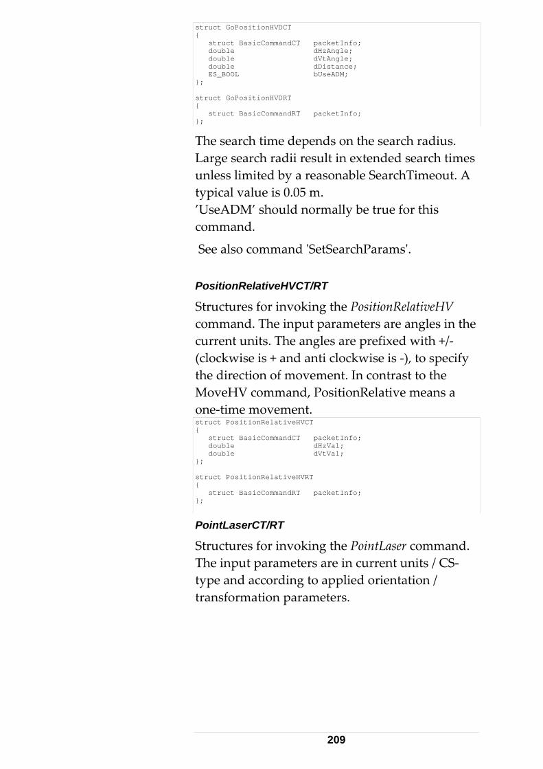
struct GoPositionHVDCT { struct BasicCommandCT packetInfo; double dHzAngle; double dVtAngle; double dDistance; ES_BOOL bUseADM; }; struct GoPositionHVDRT { struct BasicCommandRT packetInfo; };
The search time depends on the search radius. Large search radii result in extended search times unless limited by a reasonable SearchTimeout. A typical value is 0.05 m. ’UseADM’ should normally be true for this command.
See also command ʹSetSearchParamsʹ. PositionRelativeHVCT/RT
Structures for invoking the PositionRelativeHV command. The input parameters are angles in the current units. The angles are prefixed with +/‐ (clockwise is + and anti clockwise is ‐), to specify the direction of movement. In contrast to the MoveHV command, PositionRelative means a one‐time movement. struct PositionRelativeHVCT { struct BasicCommandCT packetInfo; double dHzVal; double dVtVal; }; struct PositionRelativeHVRT { struct BasicCommandRT packetInfo; };
PointLaserCT/RT
Structures for invoking the PointLaser command. The input parameters are in current units / CS‐type and according to applied orientation / transformation parameters.
209
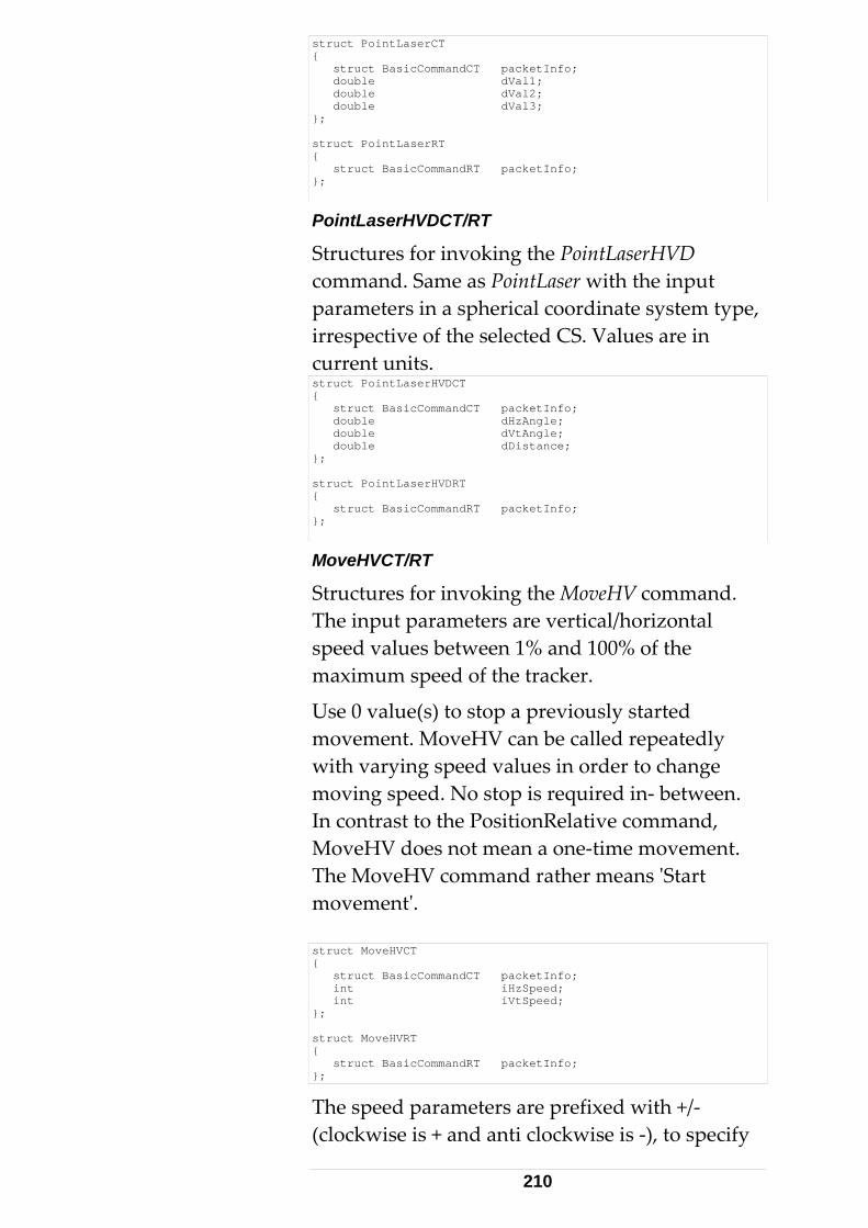
struct PointLaserCT { struct BasicCommandCT packetInfo; double dVal1; double dVal2; double dVal3; }; struct PointLaserRT { struct BasicCommandRT packetInfo; };
PointLaserHVDCT/RT
Structures for invoking the PointLaserHVD command. Same as PointLaser with the input parameters in a spherical coordinate system type, irrespective of the selected CS. Values are in current units. struct PointLaserHVDCT { struct BasicCommandCT packetInfo; double dHzAngle; double dVtAngle; double dDistance; }; struct PointLaserHVDRT { struct BasicCommandRT packetInfo; };
MoveHVCT/RT
Structures for invoking the MoveHV command. The input parameters are vertical/horizontal speed values between 1% and 100% of the maximum speed of the tracker.
Use 0 value(s) to stop a previously started movement. MoveHV can be called repeatedly with varying speed values in order to change moving speed. No stop is required in‐ between. In contrast to the PositionRelative command, MoveHV does not mean a one‐time movement. The MoveHV command rather means ʹStart movementʹ. struct MoveHVCT { struct BasicCommandCT packetInfo; int iHzSpeed; int iVtSpeed; }; struct MoveHVRT { struct BasicCommandRT packetInfo; };
The speed parameters are prefixed with +/‐ (clockwise is + and anti clockwise is ‐), to specify
210
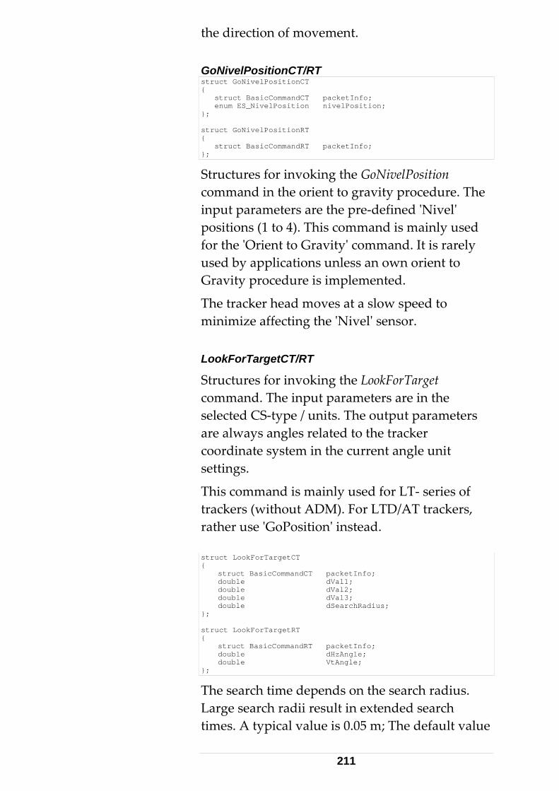
the direction of movement. GoNivelPositionCT/RT struct GoNivelPositionCT { struct BasicCommandCT packetInfo; enum ES_NivelPosition nivelPosition; }; struct GoNivelPositionRT { struct BasicCommandRT packetInfo; };
Structures for invoking the GoNivelPosition command in the orient to gravity procedure. The input parameters are the pre‐defined ʹNivelʹ positions (1 to 4). This command is mainly used for the ʹOrient to Gravityʹ command. It is rarely used by applications unless an own orient to Gravity procedure is implemented.
The tracker head moves at a slow speed to minimize affecting the ʹNivelʹ sensor. LookForTargetCT/RT
Structures for invoking the LookForTarget command. The input parameters are in the selected CS‐type / units. The output parameters are always angles related to the tracker coordinate system in the current angle unit settings.
This command is mainly used for LT‐ series of trackers (without ADM). For LTD/AT trackers, rather use ʹGoPositionʹ instead. struct LookForTargetCT { struct BasicCommandCT packetInfo; double dVal1; double dVal2; double dVal3; double dSearchRadius; }; struct LookForTargetRT { struct BasicCommandRT packetInfo; double dHzAngle; double VtAngle; };
The search time depends on the search radius. Large search radii result in extended search times. A typical value is 0.05 m; The default value
211
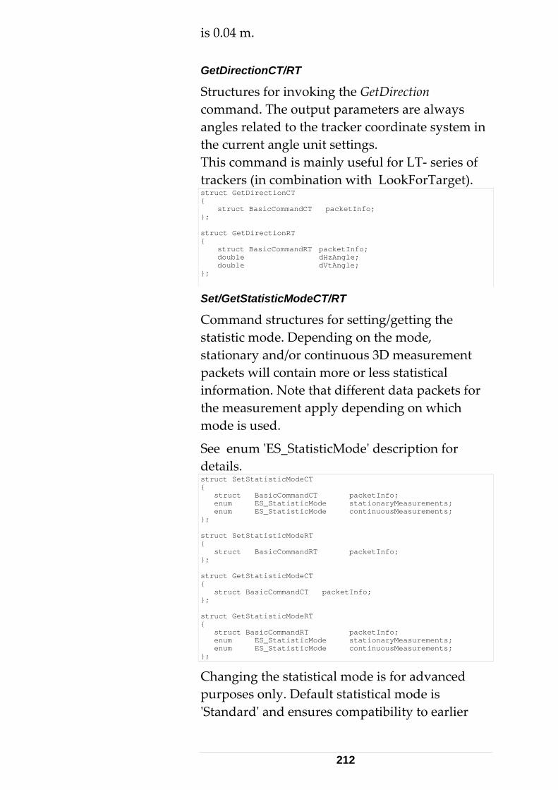
is 0.04 m. GetDirectionCT/RT
Structures for invoking the GetDirection command. The output parameters are always angles related to the tracker coordinate system in the current angle unit settings. This command is mainly useful for LT‐ series of trackers (in combination with LookForTarget). struct GetDirectionCT { struct BasicCommandCT packetInfo; }; struct GetDirectionRT { struct BasicCommandRT packetInfo; double dHzAngle; double dVtAngle; };
Set/GetStatisticModeCT/RT
Command structures for setting/getting the statistic mode. Depending on the mode, stationary and/or continuous 3D measurement packets will contain more or less statistical information. Note that different data packets for the measurement apply depending on which mode is used.
See enum ʹES_StatisticModeʹ description for details. struct SetStatisticModeCT { struct BasicCommandCT packetInfo; enum ES_StatisticMode stationaryMeasurements; enum ES_StatisticMode continuousMeasurements; }; struct SetStatisticModeRT { struct BasicCommandRT packetInfo; }; struct GetStatisticModeCT { struct BasicCommandCT packetInfo; }; struct GetStatisticModeRT { struct BasicCommandRT packetInfo; enum ES_StatisticMode stationaryMeasurements; enum ES_StatisticMode continuousMeasurements; };
Changing the statistical mode is for advanced purposes only. Default statistical mode is ʹStandardʹ and ensures compatibility to earlier
212
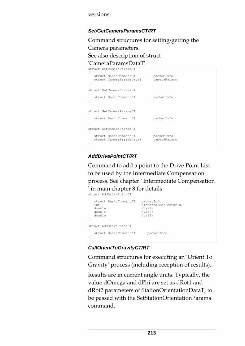
versions. Set/GetCameraParamsCT/RT
Command structures for setting/getting the Camera parameters. See also description of struct ʹCameraParamsDataTʹ. struct SetCameraParamsCT { struct BasicCommandCT packetInfo; struct CameraParamsDataT cameraParams; }; struct SetCameraParamsRT { struct BasicCommandRT packetInfo; }; struct GetCameraParamsCT { struct BasicCommandCT packetInfo; }; struct GetCameraParamsRT { struct BasicCommandRT packetInfo; struct CameraParamsDataT cameraParams; };
AddDrivePointCT/RT
Command to add a point to the Drive Point List to be used by the Intermediate Compensation process. See chapter ʹ Intermediate Compensation ʹ in main chapter 8 for details. struct AddDrivePointCT { struct BasicCommandCT packetInfo; int iInternalReflectorId; double dVal1; double dVal2; double dVal3; }; struct AddDrivePointRT { struct BasicCommandRT packetInfo; };
CallOrientToGravityCT/RT
Command structures for executing an ‘Orient To Gravity’ process (including reception of results).
Results are in current angle units. Typically, the value dOmega and dPhi are set as dRot1 and dRot2 parameters of StationOrientationDataT, to be passed with the SetStationOrientationParams command.
213
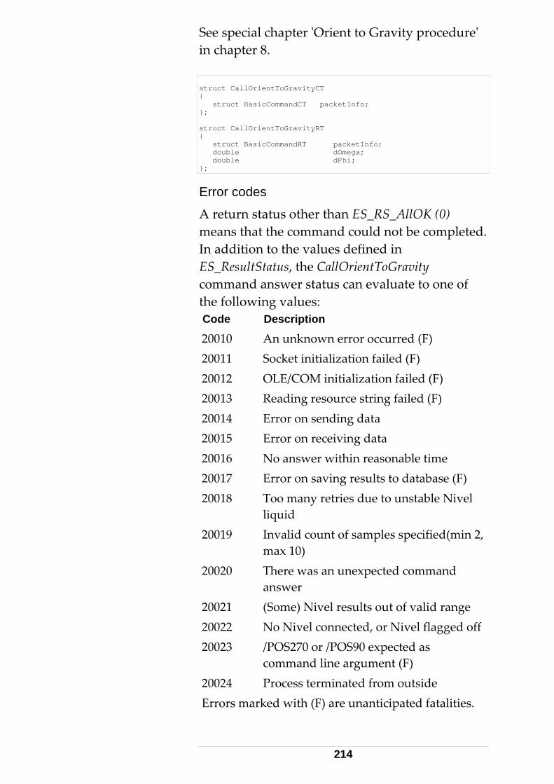
See special chapter ʹOrient to Gravity procedureʹ in chapter 8. struct CallOrientToGravityCT { struct BasicCommandCT packetInfo; }; struct CallOrientToGravityRT { struct BasicCommandRT packetInfo; double dOmega; double dPhi; };
Error codes
A return status other than ES_RS_AllOK (0) means that the command could not be completed. In addition to the values defined in ES_ResultStatus, the CallOrientToGravity command answer status can evaluate to one of the following values: Code Description
20010 An unknown error occurred (F) 20011 Socket initialization failed (F) 20012 OLE/COM initialization failed (F) 20013 Reading resource string failed (F) 20014 Error on sending data 20015 Error on receiving data 20016 No answer within reasonable time 20017 Error on saving results to database (F)
Too many retries due to unstable Nivel liquid
20018
20019 Invalid count of samples specified(min 2, max 10)
20020 There was an unexpected command answer
20021 (Some) Nivel results out of valid range 20022 No Nivel connected, or Nivel flagged off 20023 /POS270 or /POS90 expected as
command line argument (F) Process terminated from outside 20024
Errors marked with (F) are unanticipated fatalities.
214
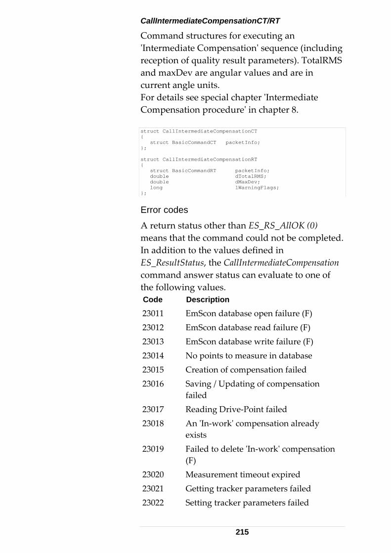
CallIntermediateCompensationCT/RT
Command structures for executing an ʹIntermediate Compensationʹ sequence (including reception of quality result parameters). TotalRMS and maxDev are angular values and are in current angle units. For details see special chapter ʹIntermediate Compensation procedureʹ in chapter 8. struct CallIntermediateCompensationCT { struct BasicCommandCT packetInfo; }; struct CallIntermediateCompensationRT { struct BasicCommandRT packetInfo; double dTotalRMS; double dMaxDev; long lWarningFlags; };
Error codes
A return status other than ES_RS_AllOK (0) means that the command could not be completed. In addition to the values defined in ES_ResultStatus, the CallIntermediateCompensation command answer status can evaluate to one of the following values. Code Description
23011 EmScon database open failure (F) 23012 EmScon database read failure (F) 23013 EmScon database write failure (F) 23014 No points to measure in database 23015 Creation of compensation failed 23016 Saving / Updating of compensation
failed 23017 Reading Drive‐Point failed 23018 An ʹIn‐workʹ compensation already
exists Failed to delete ʹIn‐workʹ compensation (F)
23019
23020 Measurement timeout expired 23021 Getting tracker parameters failed 23022 Setting tracker parameters failed
215
23023 Timeout in Positioning (no reflector within searched range?)
23030 There was a command answer other than OK (Unknown error)
23031 Sending data via TCP/IP failed (F) 23032 Error on receiving data (communication
error) (F) 23033 Process terminated from outside 23501 At least one of the 3 calculated
mechanical parameters is not in range specified.
23502 Too few (less than 2) measurements available. Calculation cannot be performed. Either not enough driving points, or not all could be found and/or measured.
23503 Minimum vertical angle difference not met
23998 An unsolicited error occurred (F) 23999 Unknown error (F) Errors marked with (F) are unanticipated fatalities.
Warning flags
Warning flags are available upon a successful compensation (Status ES_RS_AllOK [= 0]). The parameter lWarningFlags is a 32‐bit value. If the value is zero (none of the bits set), then the intermediate compensation process completed with no warnings. Otherwise, each raised bit means a particular warning. There can be more than one warning at a time.
Currently, the following warnings are possible: Bit 1 (0x1)
AverageVerticalTwoFaceErrorIsTooHigh: Tracker service (from Leica Geosystems personnel) is required because the vertical index is constantly > 1 Gon. There is currently no way for the user to reset the approximate index.
216
Bit 2 (0x2)
AtLeastOneVerticalTwoFaceErrorIsTooHigh: If Bit 1 not raised, there is probably a very high error within a single two‐face measurement. If Bit 1 is raised too, ignore warning Bit 2.
Bit 3 (0x4)
AtLeastOneDistanceIsNotInRange: At least one of the distances is smaller than the minimum or larger than the maximum recommended distance, according to the recommendations.
Bit 4 (0x8)
NotEnoughMeasInTwoOppositeVerticalPlanesWithGoodDiffOfVerticalAngle: This warning covers all (except the range criterion) possible criteria, which are not fulfilled by the measurement configuration, according to the recommendations.
Bit 5 (0x10)
NotAllCorrectedDoubledTwoFaceErrorsAreWithinCompensationTolerance: Not all measurement residuals are within recommended tolerances. NotAllMechanicalParametersAreInRange: Bit 6
(0x20) Not all three (3) mechanical parameters calculated are within recommended tolerance (according to hardware specs).
The lWarningFlags value is a decimal value. Use a scientific calculator to convert this value to a binary value to visualize the flagged bits.
Programmatically (in C/C++), a particular bit is set if the following expression evaluates to TRUE. (lWarningFlags & dwCode) // where dwCode is one of the Masks // shown above. For example. 0x10 // tests for 5th bit. See C- reference // for details (bit operations)
CallTransformationCT/RT
Command structures for executing an ‘Transformation’ process (including reception of results). Result values are in current units CS‐ type . See chapter ʹTransformation Procedureʹ in chapter 8 for details.
217
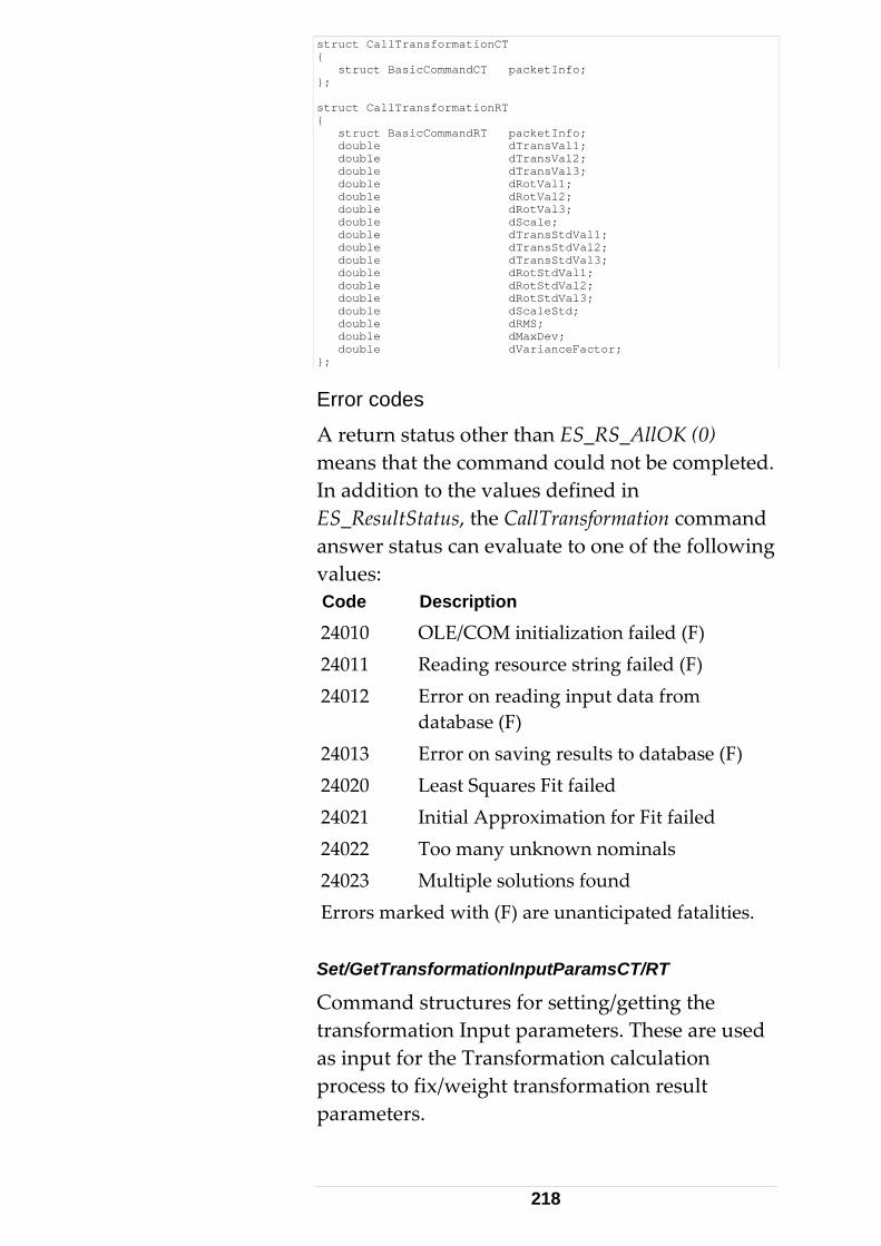
struct CallTransformationCT { struct BasicCommandCT packetInfo; }; struct CallTransformationRT { struct BasicCommandRT packetInfo; double dTransVal1; double dTransVal2; double dTransVal3; double dRotVal1; double dRotVal2; double dRotVal3; double dScale; double dTransStdVal1; double dTransStdVal2; double dTransStdVal3; double dRotStdVal1; double dRotStdVal2; double dRotStdVal3; double dScaleStd; double dRMS; double dMaxDev; double dVarianceFactor; };
Error codes
A return status other than ES_RS_AllOK (0) means that the command could not be completed. In addition to the values defined in ES_ResultStatus, the CallTransformation command answer status can evaluate to one of the following values: Code Description
24010 OLE/COM initialization failed (F) 24011 Reading resource string failed (F) 24012 Error on reading input data from
database (F) 24013 Error on saving results to database (F) 24020 Least Squares Fit failed 24021 Initial Approximation for Fit failed 24022 Too many unknown nominals 24023 Multiple solutions found Errors marked with (F) are unanticipated fatalities. Set/GetTransformationInputParamsCT/RT
Command structures for setting/getting the transformation Input parameters. These are used as input for the Transformation calculation process to fix/weight transformation result parameters.
218
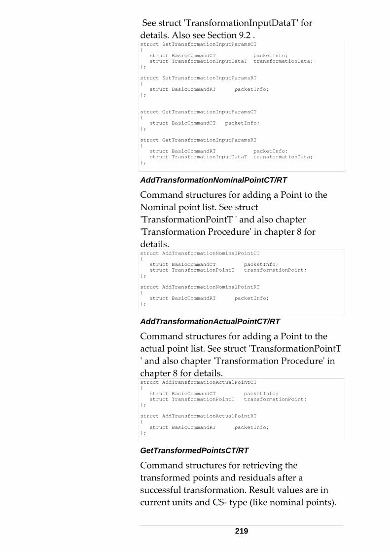
See struct ʹTransformationInputDataTʹ for details. Also see Section 9.2 . struct SetTransformationInputParamsCT { struct BasicCommandCT packetInfo; struct TransformationInputDataT transformationData; }; struct SetTransformationInputParamsRT { struct BasicCommandRT packetInfo; }; struct GetTransformationInputParamsCT { struct BasicCommandCT packetInfo; }; struct GetTransformationInputParamsRT { struct BasicCommandRT packetInfo; struct TransformationInputDataT transformationData; };
AddTransformationNominalPointCT/RT
Command structures for adding a Point to the Nominal point list. See struct ʹTransformationPointT ʹ and also chapter ʹTransformation Procedureʹ in chapter 8 for details. struct AddTransformationNominalPointCT { struct BasicCommandCT packetInfo; struct TransformationPointT transformationPoint; }; struct AddTransformationNominalPointRT { struct BasicCommandRT packetInfo; };
AddTransformationActualPointCT/RT
Command structures for adding a Point to the actual point list. See struct ʹTransformationPointT ʹ and also chapter ʹTransformation Procedureʹ in chapter 8 for details. struct AddTransformationActualPointCT { struct BasicCommandCT packetInfo; struct TransformationPointT transformationPoint; }; struct AddTransformationActualPointRT { struct BasicCommandRT packetInfo; };
GetTransformedPointsCT/RT
Command structures for retrieving the transformed points and residuals after a successful transformation. Result values are in current units and CS‐ type (like nominal points).
219
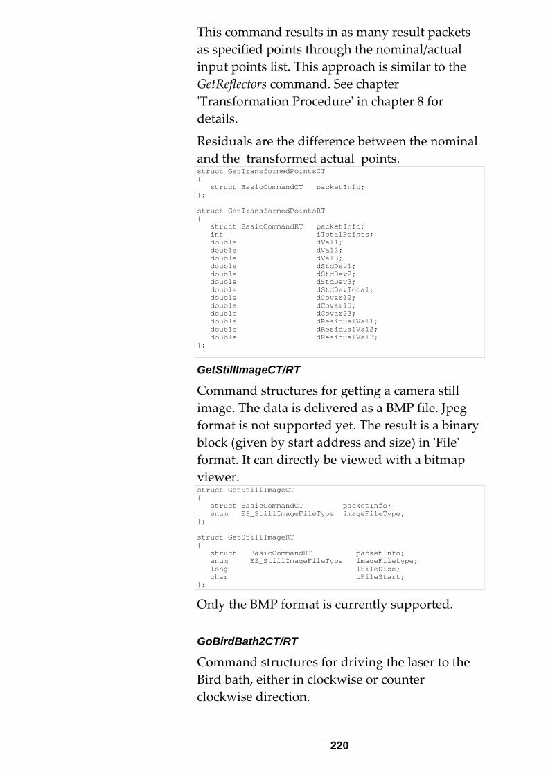
This command results in as many result packets as specified points through the nominal/actual input points list. This approach is similar to the GetReflectors command. See chapter ʹTransformation Procedureʹ in chapter 8 for details.
Residuals are the difference between the nominal and the transformed actual points. struct GetTransformedPointsCT { struct BasicCommandCT packetInfo; }; struct GetTransformedPointsRT { struct BasicCommandRT packetInfo; int iTotalPoints; double dVal1; double dVal2; double dVal3; double dStdDev1; double dStdDev2; double dStdDev3; double dStdDevTotal; double dCovar12; double dCovar13; double dCovar23; double dResidualVal1; double dResidualVal2; double dResidualVal3; };
GetStillImageCT/RT
Command structures for getting a camera still image. The data is delivered as a BMP file. Jpeg format is not supported yet. The result is a binary block (given by start address and size) in ʹFileʹ format. It can directly be viewed with a bitmap viewer. struct GetStillImageCT { struct BasicCommandCT packetInfo; enum ES_StillImageFileType imageFileType; }; struct GetStillImageRT { struct BasicCommandRT packetInfo; enum ES_StillImageFileType imageFiletype; long lFileSize; char cFileStart; };
Only the BMP format is currently supported. GoBirdBath2CT/RT
Command structures for driving the laser to the Bird bath, either in clockwise or counter clockwise direction.
220
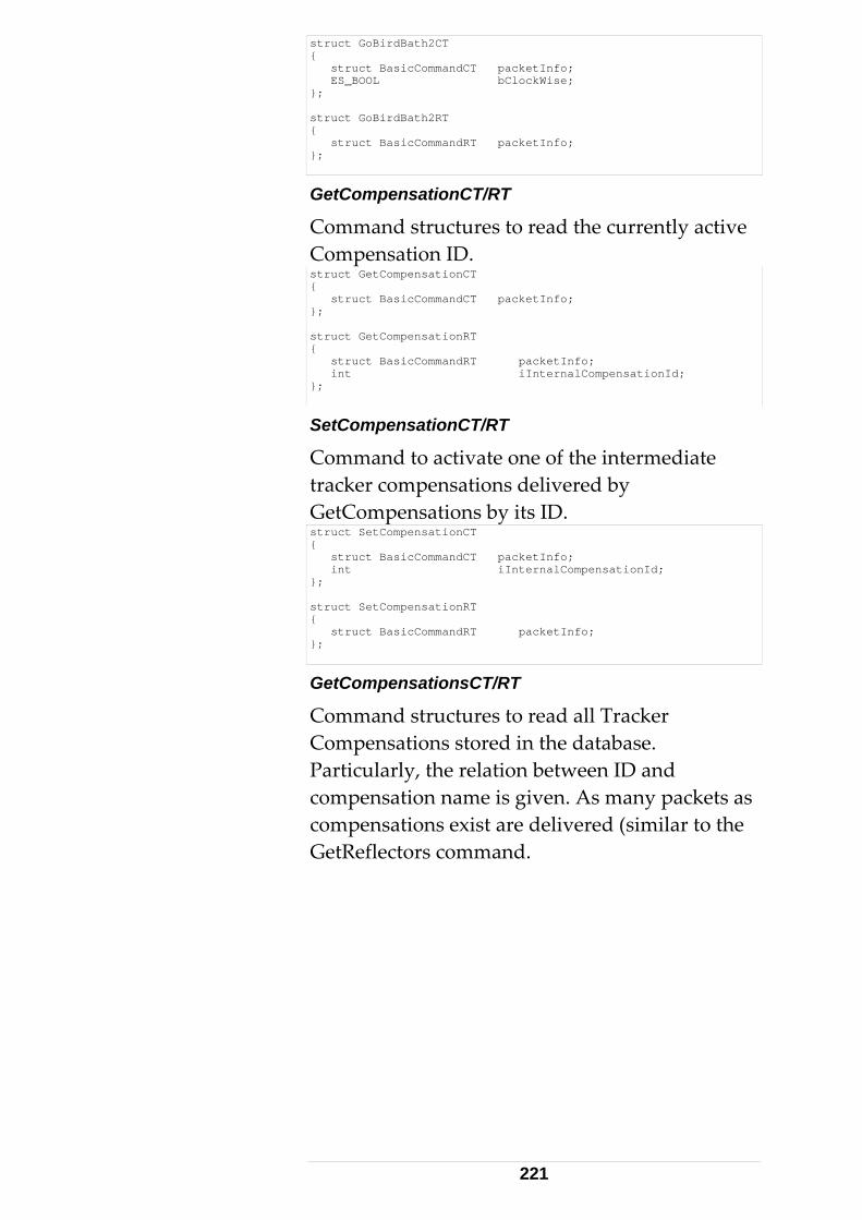
struct GoBirdBath2CT { struct BasicCommandCT packetInfo; ES_BOOL bClockWise; }; struct GoBirdBath2RT { struct BasicCommandRT packetInfo; };
GetCompensationCT/RT
Command structures to read the currently active Compensation ID. struct GetCompensationCT { struct BasicCommandCT packetInfo; }; struct GetCompensationRT { struct BasicCommandRT packetInfo; int iInternalCompensationId; };
SetCompensationCT/RT
Command to activate one of the intermediate tracker compensations delivered by GetCompensations by its ID. struct SetCompensationCT { struct BasicCommandCT packetInfo; int iInternalCompensationId; }; struct SetCompensationRT { struct BasicCommandRT packetInfo; };
GetCompensationsCT/RT
Command structures to read all Tracker Compensations stored in the database. Particularly, the relation between ID and compensation name is given. As many packets as compensations exist are delivered (similar to the GetReflectors command.
221
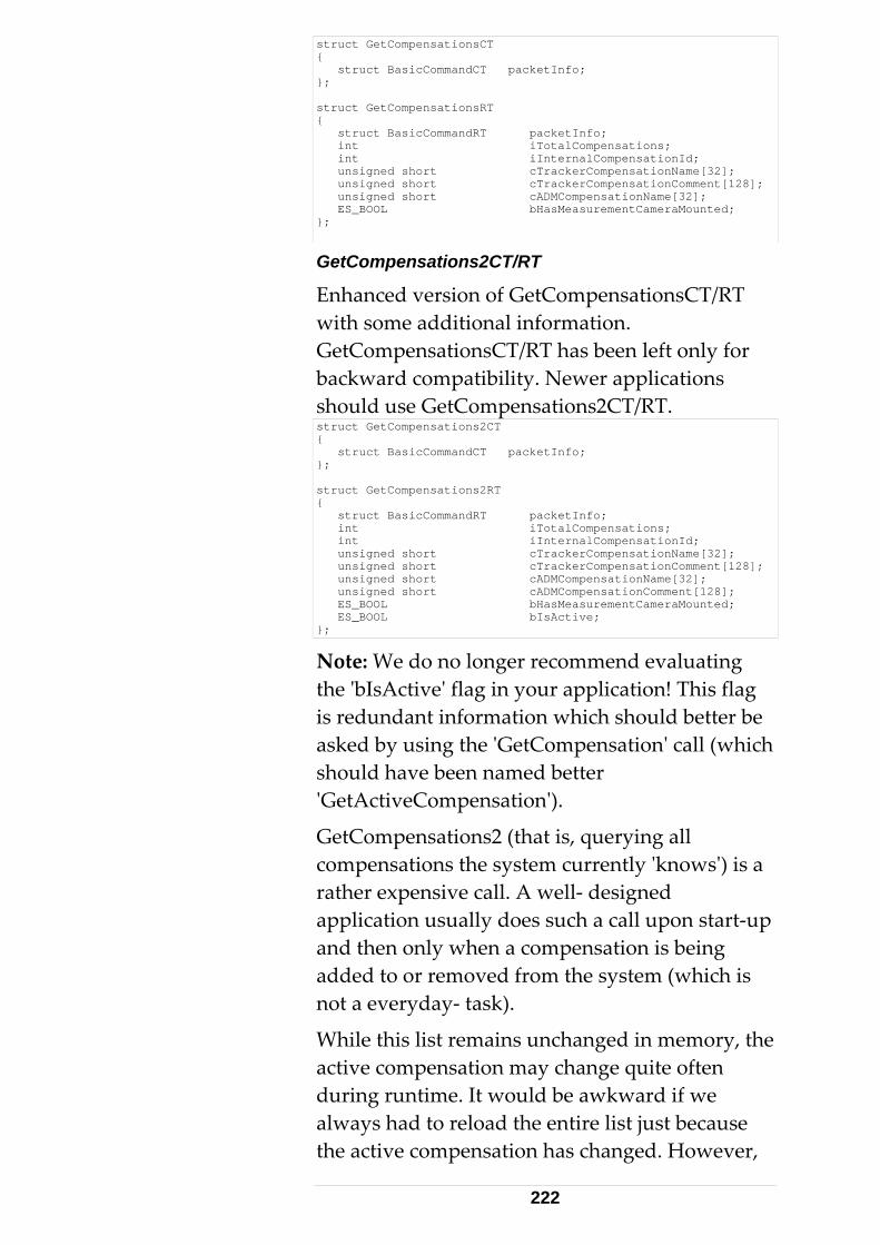
struct GetCompensationsCT { struct BasicCommandCT packetInfo; }; struct GetCompensationsRT { struct BasicCommandRT packetInfo; int iTotalCompensations; int iInternalCompensationId; unsigned short cTrackerCompensationName[32]; unsigned short cTrackerCompensationComment[128]; unsigned short cADMCompensationName[32]; ES_BOOL bHasMeasurementCameraMounted; };
GetCompensations2CT/RT
Enhanced version of GetCompensationsCT/RT with some additional information. GetCompensationsCT/RT has been left only for backward compatibility. Newer applications should use GetCompensations2CT/RT. struct GetCompensations2CT { struct BasicCommandCT packetInfo; }; struct GetCompensations2RT { struct BasicCommandRT packetInfo; int iTotalCompensations; int iInternalCompensationId; unsigned short cTrackerCompensationName[32]; unsigned short cTrackerCompensationComment[128]; unsigned short cADMCompensationName[32]; unsigned short cADMCompensationComment[128]; ES_BOOL bHasMeasurementCameraMounted; ES_BOOL bIsActive; };
Note: We do no longer recommend evaluating the ʹbIsActiveʹ flag in your application! This flag is redundant information which should better be asked by using the ʹGetCompensationʹ call (which should have been named better ʹGetActiveCompensationʹ).
GetCompensations2 (that is, querying all compensations the system currently ʹknowsʹ) is a rather expensive call. A well‐ designed application usually does such a call upon start‐up and then only when a compensation is being added to or removed from the system (which is not a everyday‐ task).
While this list remains unchanged in memory, the active compensation may change quite often during runtime. It would be awkward if we always had to reload the entire list just because the active compensation has changed. However,
222
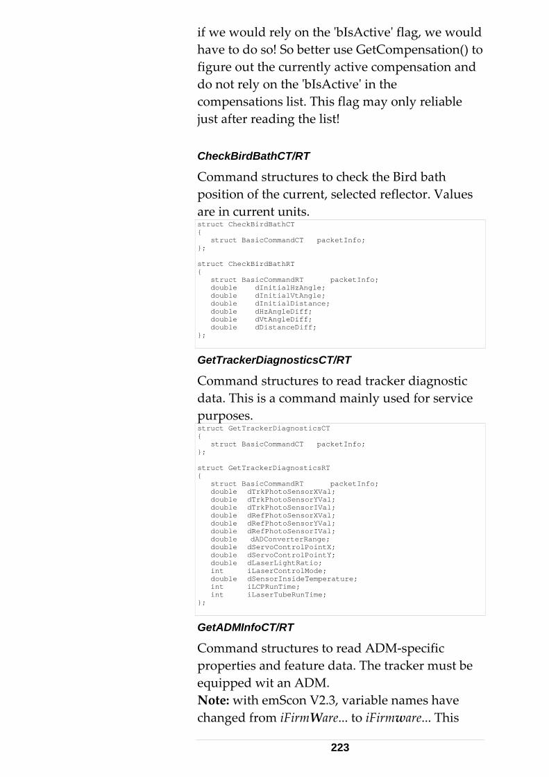
if we would rely on the ʹbIsActiveʹ flag, we would have to do so! So better use GetCompensation() to figure out the currently active compensation and do not rely on the ʹbIsActiveʹ in the compensations list. This flag may only reliable just after reading the list! CheckBirdBathCT/RT
Command structures to check the Bird bath position of the current, selected reflector. Values are in current units. struct CheckBirdBathCT { struct BasicCommandCT packetInfo; }; struct CheckBirdBathRT { struct BasicCommandRT packetInfo; double dInitialHzAngle; double dInitialVtAngle; double dInitialDistance; double dHzAngleDiff; double dVtAngleDiff; double dDistanceDiff; };
GetTrackerDiagnosticsCT/RT
Command structures to read tracker diagnostic data. This is a command mainly used for service purposes. struct GetTrackerDiagnosticsCT { struct BasicCommandCT packetInfo; }; struct GetTrackerDiagnosticsRT { struct BasicCommandRT packetInfo; double dTrkPhotoSensorXVal; double dTrkPhotoSensorYVal; double dTrkPhotoSensorIVal; double dRefPhotoSensorXVal; double dRefPhotoSensorYVal; double dRefPhotoSensorIVal; double dADConverterRange; double dServoControlPointX; double dServoControlPointY; double dLaserLightRatio; int iLaserControlMode; double dSensorInsideTemperature; int iLCPRunTime; int iLaserTubeRunTime; };
GetADMInfoCT/RT
Command structures to read ADM‐specific properties and feature data. The tracker must be equipped wit an ADM. Note: with emScon V2.3, variable names have changed from iFirmWare... to iFirmware... This
223
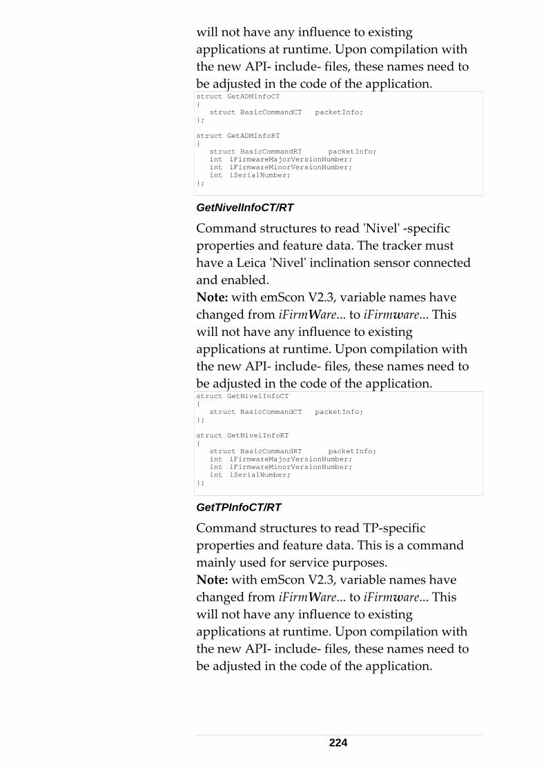
will not have any influence to existing applications at runtime. Upon compilation with the new API‐ include‐ files, these names need to be adjusted in the code of the application. struct GetADMInfoCT { struct BasicCommandCT packetInfo; }; struct GetADMInfoRT { struct BasicCommandRT packetInfo; int iFirmwareMajorVersionNumber; int iFirmwareMinorVersionNumber; int iSerialNumber; };
GetNivelInfoCT/RT
Command structures to read ʹNivelʹ ‐specific properties and feature data. The tracker must have a Leica ʹNivelʹ inclination sensor connected and enabled. Note: with emScon V2.3, variable names have changed from iFirmWare... to iFirmware... This will not have any influence to existing applications at runtime. Upon compilation with the new API‐ include‐ files, these names need to be adjusted in the code of the application. struct GetNivelInfoCT { struct BasicCommandCT packetInfo; }; struct GetNivelInfoRT { struct BasicCommandRT packetInfo; int iFirmwareMajorVersionNumber; int iFirmwareMinorVersionNumber; int iSerialNumber; };
GetTPInfoCT/RT
Command structures to read TP‐specific properties and feature data. This is a command mainly used for service purposes. Note: with emScon V2.3, variable names have changed from iFirmWare... to iFirmware... This will not have any influence to existing applications at runtime. Upon compilation with the new API‐ include‐ files, these names need to be adjusted in the code of the application.
224
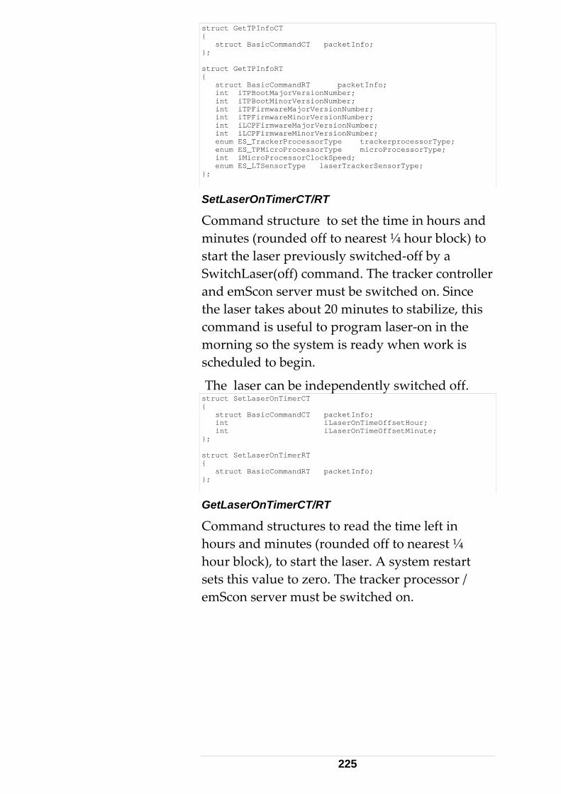
struct GetTPInfoCT { struct BasicCommandCT packetInfo; }; struct GetTPInfoRT { struct BasicCommandRT packetInfo; int iTPBootMajorVersionNumber; int iTPBootMinorVersionNumber; int iTPFirmwareMajorVersionNumber; int iTPFirmwareMinorVersionNumber; int iLCPFirmwareMajorVersionNumber; int iLCPFirmwareMinorVersionNumber; enum ES_TrackerProcessorType trackerprocessorType; enum ES_TPMicroProcessorType microProcessorType; int iMicroProcessorClockSpeed; enum ES_LTSensorType laserTrackerSensorType; };
SetLaserOnTimerCT/RT
Command structure to set the time in hours and minutes (rounded off to nearest ¼ hour block) to start the laser previously switched‐off by a SwitchLaser(off) command. The tracker controller and emScon server must be switched on. Since the laser takes about 20 minutes to stabilize, this command is useful to program laser‐on in the morning so the system is ready when work is scheduled to begin.
The laser can be independently switched off. struct SetLaserOnTimerCT { struct BasicCommandCT packetInfo; int iLaserOnTimeOffsetHour; int iLaserOnTimeOffsetMinute; }; struct SetLaserOnTimerRT { struct BasicCommandRT packetInfo; };
GetLaserOnTimerCT/RT
Command structures to read the time left in hours and minutes (rounded off to nearest ¼ hour block), to start the laser. A system restart sets this value to zero. The tracker processor / emScon server must be switched on.
225
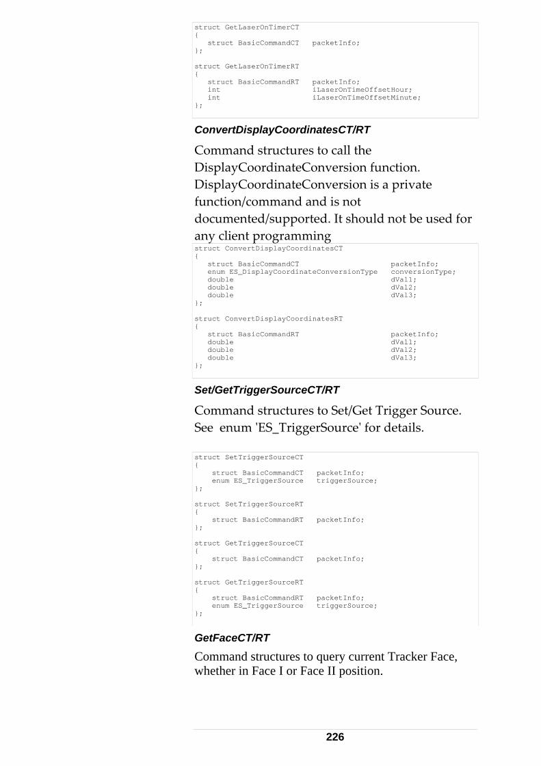
struct GetLaserOnTimerCT { struct BasicCommandCT packetInfo; }; struct GetLaserOnTimerRT { struct BasicCommandRT packetInfo; int iLaserOnTimeOffsetHour; int iLaserOnTimeOffsetMinute; };
ConvertDisplayCoordinatesCT/RT
Command structures to call the DisplayCoordinateConversion function. DisplayCoordinateConversion is a private function/command and is not documented/supported. It should not be used for any client programming struct ConvertDisplayCoordinatesCT { struct BasicCommandCT packetInfo; enum ES_DisplayCoordinateConversionType conversionType; double dVal1; double dVal2; double dVal3; }; struct ConvertDisplayCoordinatesRT { struct BasicCommandRT packetInfo; double dVal1; double dVal2; double dVal3; };
Set/GetTriggerSourceCT/RT
Command structures to Set/Get Trigger Source. See enum ʹES_TriggerSourceʹ for details. struct SetTriggerSourceCT { struct BasicCommandCT packetInfo; enum ES_TriggerSource triggerSource; }; struct SetTriggerSourceRT { struct BasicCommandRT packetInfo; }; struct GetTriggerSourceCT { struct BasicCommandCT packetInfo; }; struct GetTriggerSourceRT { struct BasicCommandRT packetInfo; enum ES_TriggerSource triggerSource; };
GetFaceCT/RT
Command structures to query current Tracker Face, whether in Face I or Face II position.
226
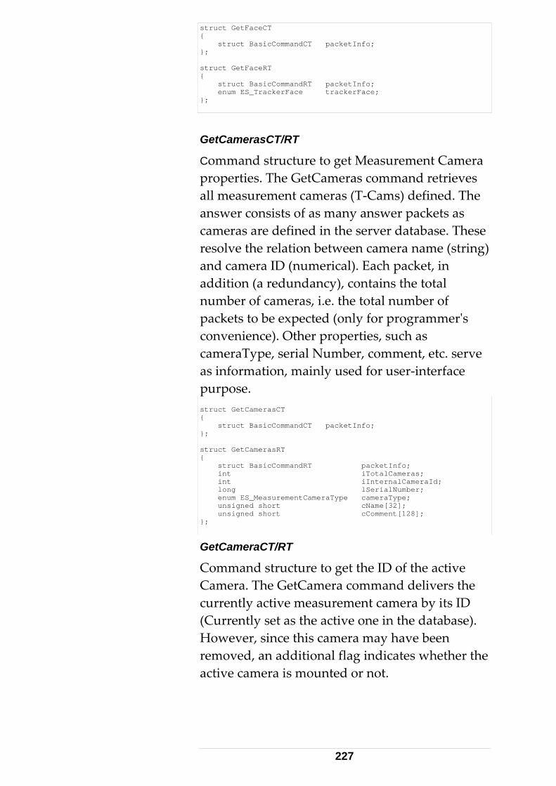
struct GetFaceCT { struct BasicCommandCT packetInfo; }; struct GetFaceRT { struct BasicCommandRT packetInfo; enum ES_TrackerFace trackerFace; };
GetCamerasCT/RT
Command structure to get Measurement Camera properties. The GetCameras command retrieves all measurement cameras (T‐Cams) defined. The answer consists of as many answer packets as cameras are defined in the server database. These resolve the relation between camera name (string) and camera ID (numerical). Each packet, in addition (a redundancy), contains the total number of cameras, i.e. the total number of packets to be expected (only for programmerʹs convenience). Other properties, such as cameraType, serial Number, comment, etc. serve as information, mainly used for user‐interface purpose. struct GetCamerasCT { struct BasicCommandCT packetInfo; }; struct GetCamerasRT { struct BasicCommandRT packetInfo; int iTotalCameras; int iInternalCameraId; long lSerialNumber; enum ES_MeasurementCameraType cameraType; unsigned short cName[32]; unsigned short cComment[128]; };
GetCameraCT/RT
Command structure to get the ID of the active Camera. The GetCamera command delivers the currently active measurement camera by its ID (Currently set as the active one in the database). However, since this camera may have been removed, an additional flag indicates whether the active camera is mounted or not.
227
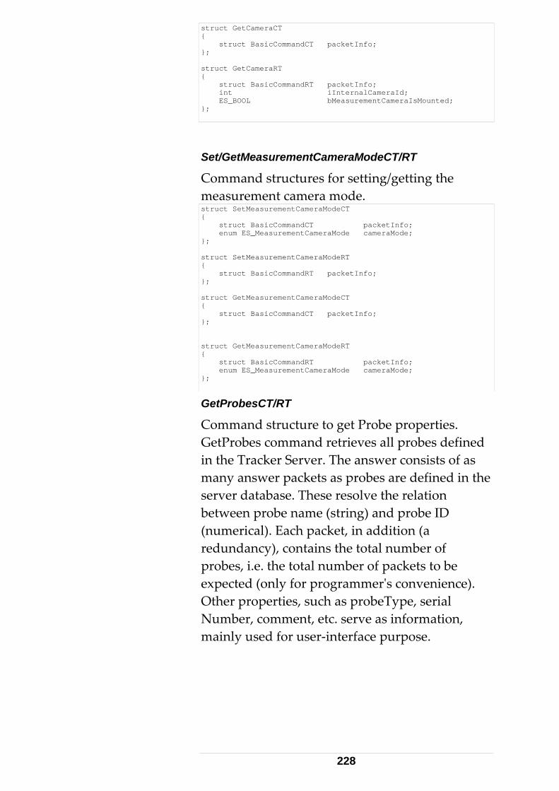
struct GetCameraCT { struct BasicCommandCT packetInfo; }; struct GetCameraRT { struct BasicCommandRT packetInfo; int iInternalCameraId; ES_BOOL bMeasurementCameraIsMounted; };
Set/GetMeasurementCameraModeCT/RT
Command structures for setting/getting the measurement camera mode. struct SetMeasurementCameraModeCT { struct BasicCommandCT packetInfo; enum ES_MeasurementCameraMode cameraMode; }; struct SetMeasurementCameraModeRT { struct BasicCommandRT packetInfo; }; struct GetMeasurementCameraModeCT { struct BasicCommandCT packetInfo; }; struct GetMeasurementCameraModeRT { struct BasicCommandRT packetInfo; enum ES_MeasurementCameraMode cameraMode; };
GetProbesCT/RT
Command structure to get Probe properties. GetProbes command retrieves all probes defined in the Tracker Server. The answer consists of as many answer packets as probes are defined in the server database. These resolve the relation between probe name (string) and probe ID (numerical). Each packet, in addition (a redundancy), contains the total number of probes, i.e. the total number of packets to be expected (only for programmerʹs convenience). Other properties, such as probeType, serial Number, comment, etc. serve as information, mainly used for user‐interface purpose.
228
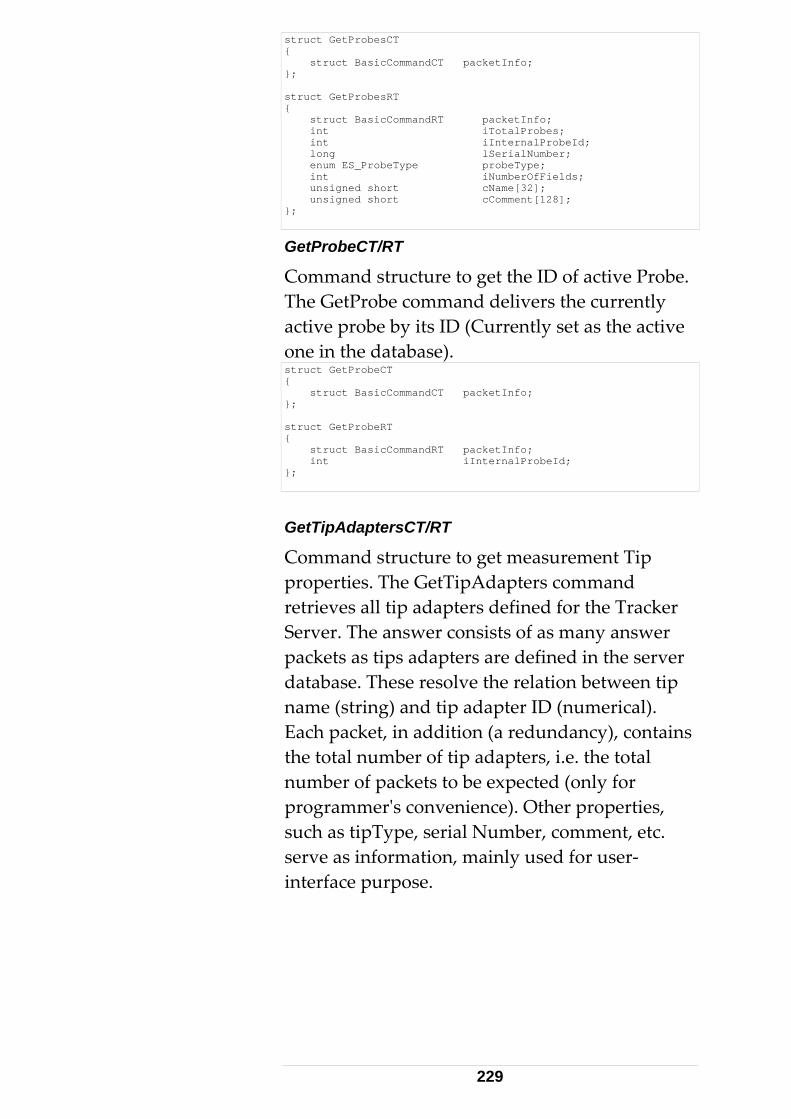
struct GetProbesCT { struct BasicCommandCT packetInfo; }; struct GetProbesRT { struct BasicCommandRT packetInfo; int iTotalProbes; int iInternalProbeId; long lSerialNumber; enum ES_ProbeType probeType; int iNumberOfFields; unsigned short cName[32]; unsigned short cComment[128]; };
GetProbeCT/RT
Command structure to get the ID of active Probe. The GetProbe command delivers the currently active probe by its ID (Currently set as the active one in the database). struct GetProbeCT { struct BasicCommandCT packetInfo; }; struct GetProbeRT { struct BasicCommandRT packetInfo; int iInternalProbeId; };
GetTipAdaptersCT/RT
Command structure to get measurement Tip properties. The GetTipAdapters command retrieves all tip adapters defined for the Tracker Server. The answer consists of as many answer packets as tips adapters are defined in the server database. These resolve the relation between tip name (string) and tip adapter ID (numerical). Each packet, in addition (a redundancy), contains the total number of tip adapters, i.e. the total number of packets to be expected (only for programmerʹs convenience). Other properties, such as tipType, serial Number, comment, etc. serve as information, mainly used for user‐interface purpose.
229
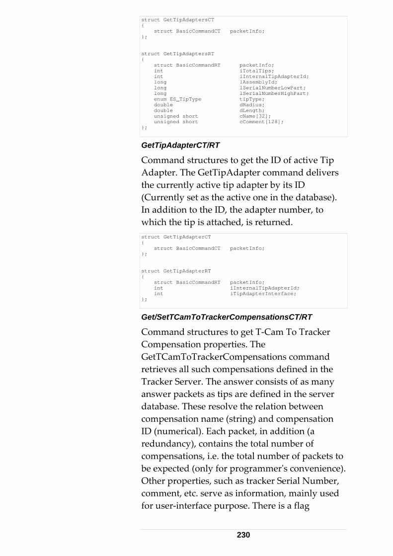
struct GetTipAdaptersCT { struct BasicCommandCT packetInfo; }; struct GetTipAdaptersRT { struct BasicCommandRT packetInfo; int iTotalTips; int iInternalTipAdapterId; long lAssemblyId; long lSerialNumberLowPart; long lSerialNumberHighPart; enum ES_TipType tipType; double dRadius; double dLength; unsigned short cName[32]; unsigned short cComment[128]; };
GetTipAdapterCT/RT
Command structures to get the ID of active Tip Adapter. The GetTipAdapter command delivers the currently active tip adapter by its ID (Currently set as the active one in the database). In addition to the ID, the adapter number, to which the tip is attached, is returned. struct GetTipAdapterCT { struct BasicCommandCT packetInfo; }; struct GetTipAdapterRT { struct BasicCommandRT packetInfo; int iInternalTipAdapterId; int iTipAdapterInterface; };
Get/SetTCamToTrackerCompensationsCT/RT
Command structures to get T‐Cam To Tracker Compensation properties. The GetTCamToTrackerCompensations command retrieves all such compensations defined in the Tracker Server. The answer consists of as many answer packets as tips are defined in the server database. These resolve the relation between compensation name (string) and compensation ID (numerical). Each packet, in addition (a redundancy), contains the total number of compensations, i.e. the total number of packets to be expected (only for programmerʹs convenience). Other properties, such as tracker Serial Number, comment, etc. serve as information, mainly used for user‐interface purpose. There is a flag
230
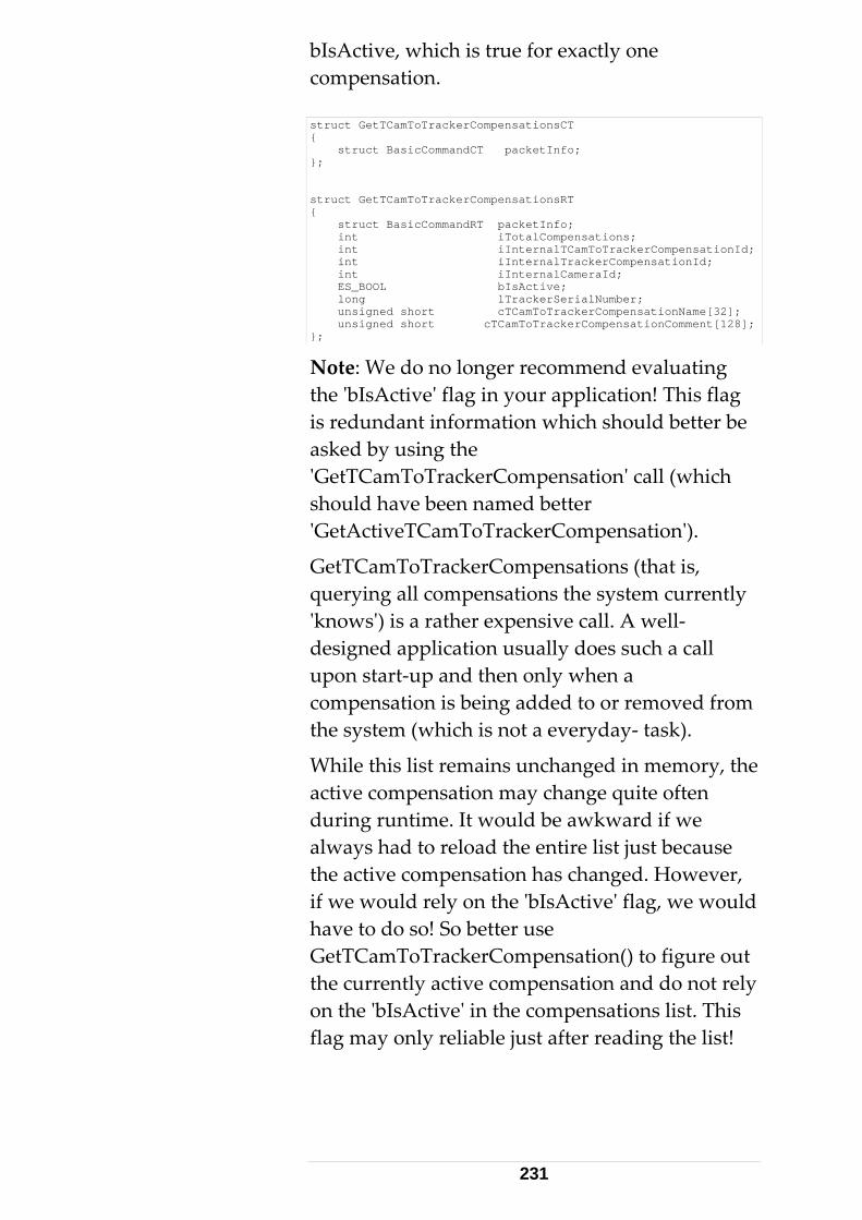
bIsActive, which is true for exactly one compensation. struct GetTCamToTrackerCompensationsCT { struct BasicCommandCT packetInfo; }; struct GetTCamToTrackerCompensationsRT { struct BasicCommandRT packetInfo; int iTotalCompensations; int iInternalTCamToTrackerCompensationId; int iInternalTrackerCompensationId; int iInternalCameraId; ES_BOOL bIsActive; long lTrackerSerialNumber; unsigned short cTCamToTrackerCompensationName[32]; unsigned short cTCamToTrackerCompensationComment[128]; };
Note: We do no longer recommend evaluating the ʹbIsActiveʹ flag in your application! This flag is redundant information which should better be asked by using the ʹGetTCamToTrackerCompensationʹ call (which should have been named better ʹGetActiveTCamToTrackerCompensationʹ).
GetTCamToTrackerCompensations (that is, querying all compensations the system currently ʹknowsʹ) is a rather expensive call. A well‐ designed application usually does such a call upon start‐up and then only when a compensation is being added to or removed from the system (which is not a everyday‐ task).
While this list remains unchanged in memory, the active compensation may change quite often during runtime. It would be awkward if we always had to reload the entire list just because the active compensation has changed. However, if we would rely on the ʹbIsActiveʹ flag, we would have to do so! So better use GetTCamToTrackerCompensation() to figure out the currently active compensation and do not rely on the ʹbIsActiveʹ in the compensations list. This flag may only reliable just after reading the list!
231
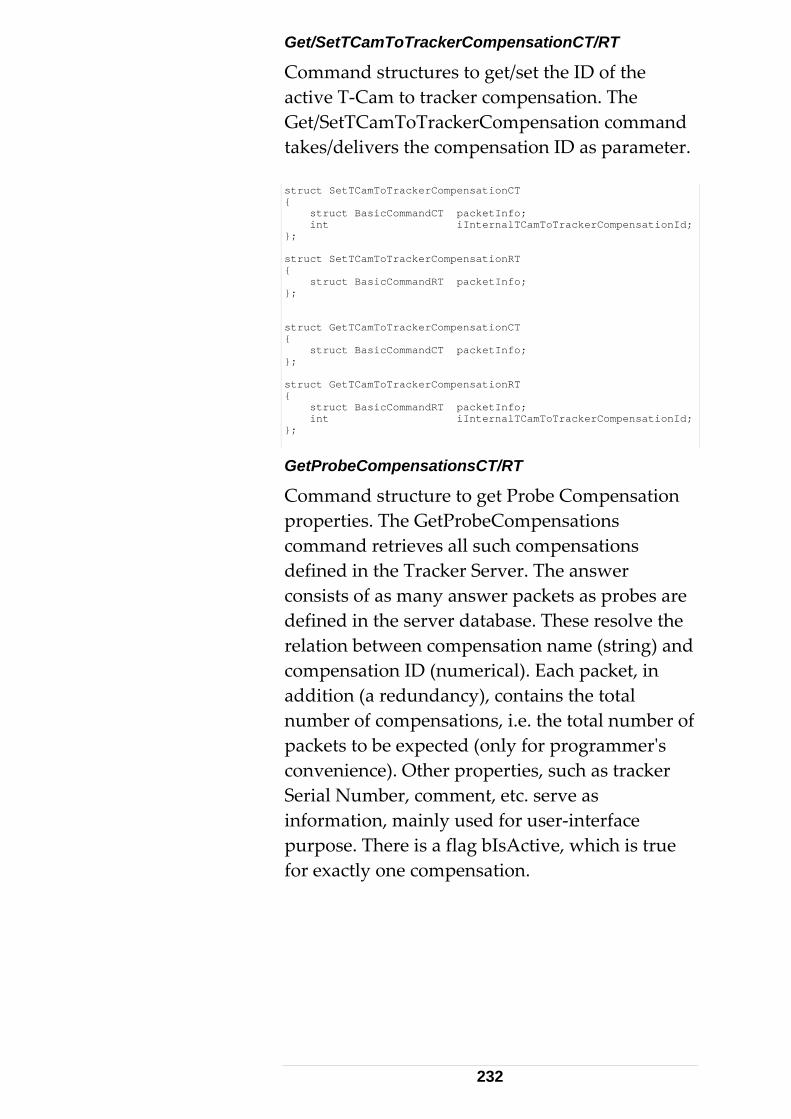
Get/SetTCamToTrackerCompensationCT/RT
Command structures to get/set the ID of the active T‐Cam to tracker compensation. The Get/SetTCamToTrackerCompensation command takes/delivers the compensation ID as parameter. struct SetTCamToTrackerCompensationCT { struct BasicCommandCT packetInfo; int iInternalTCamToTrackerCompensationId; }; struct SetTCamToTrackerCompensationRT { struct BasicCommandRT packetInfo; }; struct GetTCamToTrackerCompensationCT { struct BasicCommandCT packetInfo; }; struct GetTCamToTrackerCompensationRT { struct BasicCommandRT packetInfo; int iInternalTCamToTrackerCompensationId; };
GetProbeCompensationsCT/RT
Command structure to get Probe Compensation properties. The GetProbeCompensations command retrieves all such compensations defined in the Tracker Server. The answer consists of as many answer packets as probes are defined in the server database. These resolve the relation between compensation name (string) and compensation ID (numerical). Each packet, in addition (a redundancy), contains the total number of compensations, i.e. the total number of packets to be expected (only for programmerʹs convenience). Other properties, such as tracker Serial Number, comment, etc. serve as information, mainly used for user‐interface purpose. There is a flag bIsActive, which is true for exactly one compensation.
232
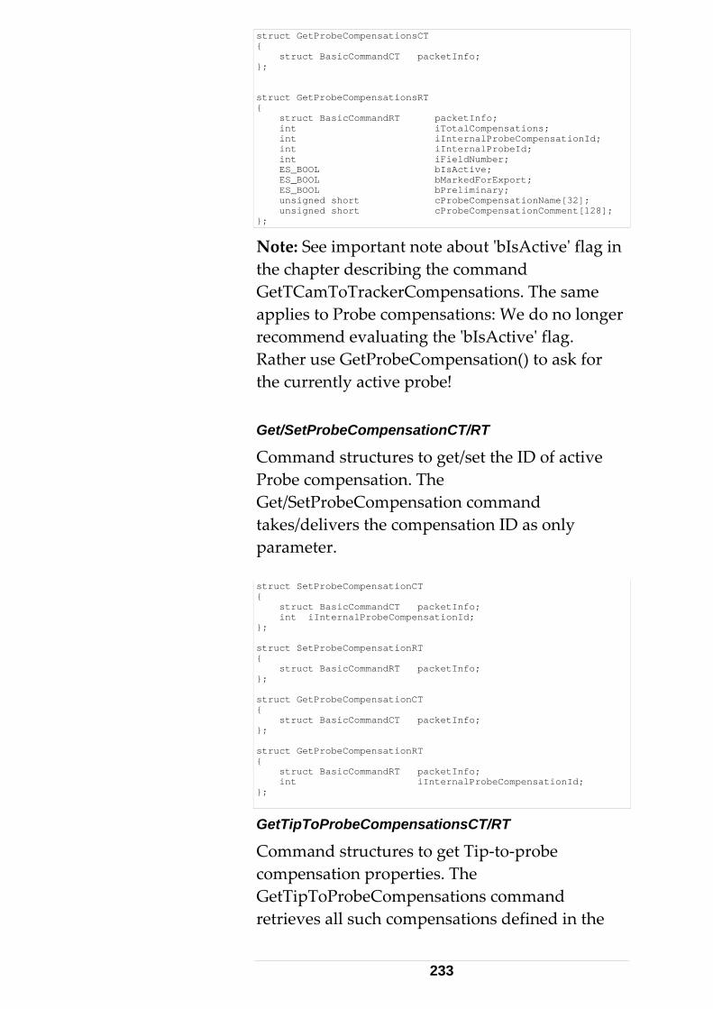
struct GetProbeCompensationsCT { struct BasicCommandCT packetInfo; }; struct GetProbeCompensationsRT { struct BasicCommandRT packetInfo; int iTotalCompensations; int iInternalProbeCompensationId; int iInternalProbeId; int iFieldNumber; ES_BOOL bIsActive; ES_BOOL bMarkedForExport; ES_BOOL bPreliminary; unsigned short cProbeCompensationName[32]; unsigned short cProbeCompensationComment[128]; };
Note: See important note about ʹbIsActiveʹ flag in the chapter describing the command GetTCamToTrackerCompensations. The same applies to Probe compensations: We do no longer recommend evaluating the ʹbIsActiveʹ flag. Rather use GetProbeCompensation() to ask for the currently active probe! Get/SetProbeCompensationCT/RT
Command structures to get/set the ID of active Probe compensation. The Get/SetProbeCompensation command takes/delivers the compensation ID as only parameter. struct SetProbeCompensationCT { struct BasicCommandCT packetInfo; int iInternalProbeCompensationId; }; struct SetProbeCompensationRT { struct BasicCommandRT packetInfo; }; struct GetProbeCompensationCT { struct BasicCommandCT packetInfo; }; struct GetProbeCompensationRT { struct BasicCommandRT packetInfo; int iInternalProbeCompensationId; };
GetTipToProbeCompensationsCT/RT
Command structures to get Tip‐to‐probe compensation properties. The GetTipToProbeCompensations command retrieves all such compensations defined in the
233
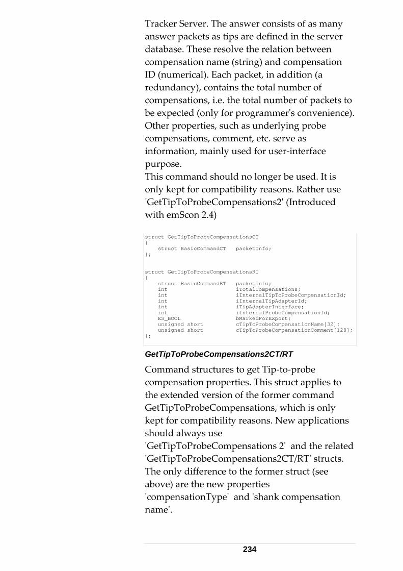
Tracker Server. The answer consists of as many answer packets as tips are defined in the server database. These resolve the relation between compensation name (string) and compensation ID (numerical). Each packet, in addition (a redundancy), contains the total number of compensations, i.e. the total number of packets to be expected (only for programmerʹs convenience). Other properties, such as underlying probe compensations, comment, etc. serve as information, mainly used for user‐interface purpose. This command should no longer be used. It is only kept for compatibility reasons. Rather use ʹGetTipToProbeCompensations2ʹ (Introduced with emScon 2.4) struct GetTipToProbeCompensationsCT { struct BasicCommandCT packetInfo; }; struct GetTipToProbeCompensationsRT { struct BasicCommandRT packetInfo; int iTotalCompensations; int iInternalTipToProbeCompensationId; int iInternalTipAdapterId; int iTipAdapterInterface; int iInternalProbeCompensationId; ES_BOOL bMarkedForExport; unsigned short cTipToProbeCompensationName[32]; unsigned short cTipToProbeCompensationComment[128]; };
GetTipToProbeCompensations2CT/RT
Command structures to get Tip‐to‐probe compensation properties. This struct applies to the extended version of the former command GetTipToProbeCompensations, which is only kept for compatibility reasons. New applications should always use ʹGetTipToProbeCompensations 2ʹ and the related ʹGetTipToProbeCompensations2CT/RTʹ structs. The only difference to the former struct (see above) are the new properties ʹcompensationTypeʹ and ʹshank compensation nameʹ.
234
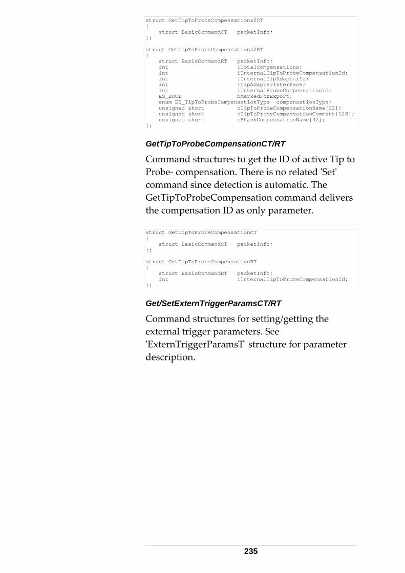
struct GetTipToProbeCompensations2CT { struct BasicCommandCT packetInfo; }; struct GetTipToProbeCompensations2RT { struct BasicCommandRT packetInfo; int iTotalCompensations; int iInternalTipToProbeCompensationId; int iInternalTipAdapterId; int iTipAdapterInterface; int iInternalProbeCompensationId; ES_BOOL bMarkedForExport; enum ES_TipToProbeCompensationType compensationType; unsigned short cTipToProbeCompensationName[32]; unsigned short cTipToProbeCompensationComment[128]; unsigned short cShankCompensationName[32]; };
GetTipToProbeCompensationCT/RT
Command structures to get the ID of active Tip to Probe‐ compensation. There is no related ʹSetʹ command since detection is automatic. The GetTipToProbeCompensation command delivers the compensation ID as only parameter. struct GetTipToProbeCompensationCT { struct BasicCommandCT packetInfo; }; struct GetTipToProbeCompensationRT { struct BasicCommandRT packetInfo; int iInternalTipToProbeCompensationId; };
Get/SetExternTriggerParamsCT/RT
Command structures for setting/getting the external trigger parameters. See ʹExternTriggerParamsTʹ structure for parameter description.
235
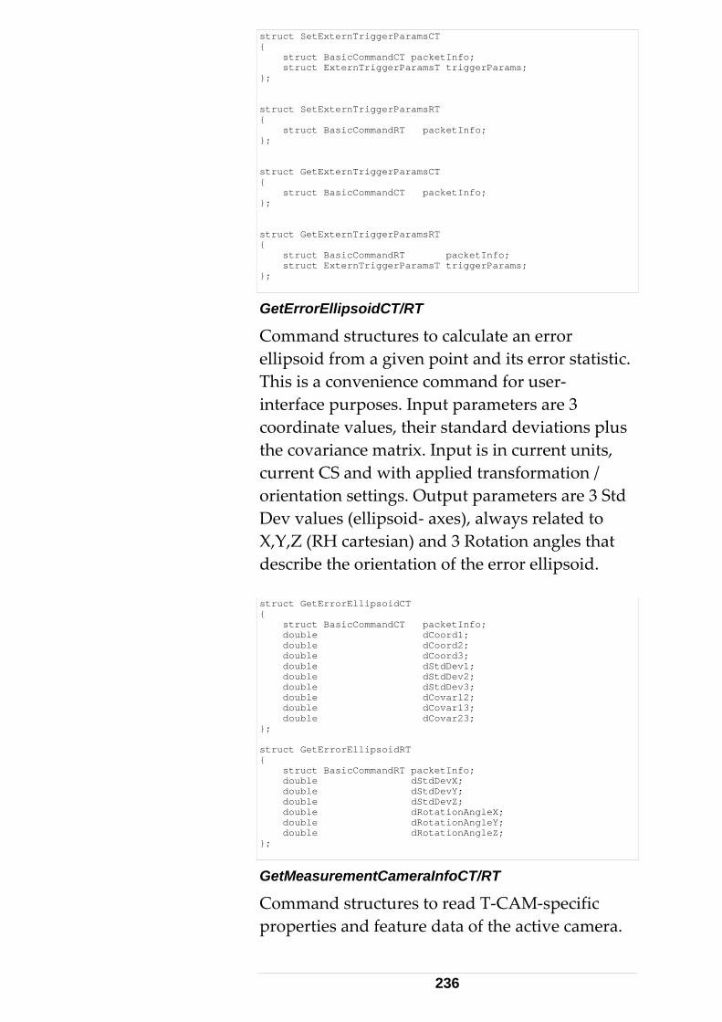
struct SetExternTriggerParamsCT { struct BasicCommandCT packetInfo; struct ExternTriggerParamsT triggerParams; }; struct SetExternTriggerParamsRT { struct BasicCommandRT packetInfo; }; struct GetExternTriggerParamsCT { struct BasicCommandCT packetInfo; }; struct GetExternTriggerParamsRT { struct BasicCommandRT packetInfo; struct ExternTriggerParamsT triggerParams; };
GetErrorEllipsoidCT/RT
Command structures to calculate an error ellipsoid from a given point and its error statistic. This is a convenience command for user‐ interface purposes. Input parameters are 3 coordinate values, their standard deviations plus the covariance matrix. Input is in current units, current CS and with applied transformation / orientation settings. Output parameters are 3 Std Dev values (ellipsoid‐ axes), always related to X,Y,Z (RH cartesian) and 3 Rotation angles that describe the orientation of the error ellipsoid. struct GetErrorEllipsoidCT { struct BasicCommandCT packetInfo; double dCoord1; double dCoord2; double dCoord3; double dStdDev1; double dStdDev2; double dStdDev3; double dCovar12; double dCovar13; double dCovar23; }; struct GetErrorEllipsoidRT { struct BasicCommandRT packetInfo; double dStdDevX; double dStdDevY; double dStdDevZ; double dRotationAngleX; double dRotationAngleY; double dRotationAngleZ; };
GetMeasurementCameraInfoCT/RT
Command structures to read T‐CAM‐specific properties and feature data of the active camera.
236
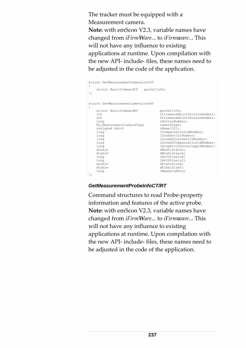
The tracker must be equipped with a Measurement camera. Note: with emScon V2.3, variable names have changed from iFirmWare... to iFirmware... This will not have any influence to existing applications at runtime. Upon compilation with the new API‐ include‐ files, these names need to be adjusted in the code of the application. struct GetMeasurementCameraInfoCT { struct BasicCommandCT packetInfo; }; struct GetMeasurementCameraInfoRT { struct BasicCommandRT packetInfo; int iFirmwareMajorVersionNumber; int iFirmwareMinorVersionNumber; long lSerialNumber; ES_MeasurementCameraType cameraType; unsigned short cName[32]; long lCompensationIdNumber; long lZoomSerialNumber; long lZoomAdjustmentIdNumber; long lZoom2DCompensationIdNumber; long lZoomProjCenterCompIdNumber; double dMaxDistance; double dMinDistance; long lNrOfPixelsX; long lNrOfPixelsY; double dPixelSizeX; double dPixelSizeY; long lMaxDataRate; };
GetMeasurementProbeInfoCT/RT
Command structures to read Probe‐property information and features of the active probe. Note: with emScon V2.3, variable names have changed from iFirmWare... to iFirmware... This will not have any influence to existing applications at runtime. Upon compilation with the new API‐ include‐ files, these names need to be adjusted in the code of the application.
237
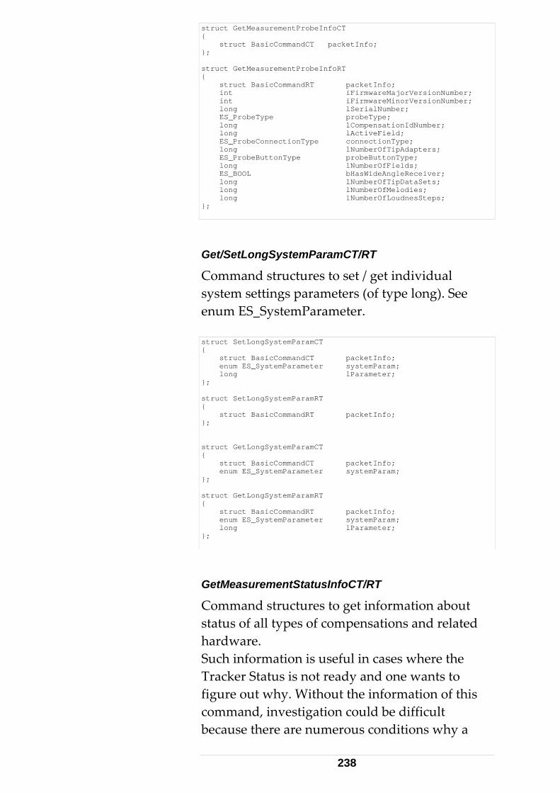
struct GetMeasurementProbeInfoCT { struct BasicCommandCT packetInfo; }; struct GetMeasurementProbeInfoRT { struct BasicCommandRT packetInfo; int iFirmwareMajorVersionNumber; int iFirmwareMinorVersionNumber; long lSerialNumber; ES_ProbeType probeType; long lCompensationIdNumber; long lActiveField; ES_ProbeConnectionType connectionType; long lNumberOfTipAdapters; ES_ProbeButtonType probeButtonType; long lNumberOfFields; ES_BOOL bHasWideAngleReceiver; long lNumberOfTipDataSets; long lNumberOfMelodies; long lNumberOfLoudnesSteps; };
Get/SetLongSystemParamCT/RT
Command structures to set / get individual system settings parameters (of type long). See enum ES_SystemParameter. struct SetLongSystemParamCT { struct BasicCommandCT packetInfo; enum ES_SystemParameter systemParam; long lParameter; }; struct SetLongSystemParamRT { struct BasicCommandRT packetInfo; }; struct GetLongSystemParamCT { struct BasicCommandCT packetInfo; enum ES_SystemParameter systemParam; }; struct GetLongSystemParamRT { struct BasicCommandRT packetInfo; enum ES_SystemParameter systemParam; long lParameter; };
GetMeasurementStatusInfoCT/RT
Command structures to get information about status of all types of compensations and related hardware. Such information is useful in cases where the Tracker Status is not ready and one wants to figure out why. Without the information of this command, investigation could be difficult because there are numerous conditions why a
238
system is not ready to measure (Missing compensations, Beam not attached, no accurate Reflector). This especially applies to 6DoF modes. A look to the bits of ‘lMeasurementStatusInfo’ immediately shows the reason. The information data is delivered as a long value representing a bit‐mask. Use the enum ES_MeasurementStatusInfo values to decode / mask the ʹlMeasurementStatusInfoʹ parameters flags information. Note the terminology with the ʹsʹ: GetMeasurementStatusInfo. This is because this command relates to different types of compensations and hardware (which are always related) struct GetMeasurementStatusInfoCT { struct BasicCommandCT packetInfo; }; struct GetMeasurementStatusInfoRT { struct BasicCommandRT packetInfo; enum ES_ResultStatus lastResultStatus; long lMeasurementStatusInfo; };
GetCurrentPrismPositionCT/RT
Command structures to get the 3D position of the prism the laser is currently attached to. Delivers the ‘same’ values as a stationary measurement would deliver, however, less accurate than stationary measurements. Do NOT use these values as measurements where precise measurements are required. See command description ‘GetCurrentPrismPosition’ for a typical application of this command.
239
struct GetCurrentPrismPositionCT { struct BasicCommandCT packetInfo; }; struct GetCurrentPrismPositionRT { struct BasicCommandRT packetInfo; double dVal1; double dVal2; double dVal3; };
GetObjectTemperatureCT
Command structures for the GetObjectTemperature command. Details see description of ES_Command: ES_C_GetObjectTemperature. struct GetObjectTemperatureCT { struct BasicCommandCT packetInfo; }; struct GetObjectTemperatureRT { struct BasicCommandRT packetInfo; double dObjectTemperature; };
ClearCommandQueueCT/RT
Command structures for the ClearCommandQueue command. Input parameter clearQueueType: see enum ES_ClearCommandQueueType. This is for advanced programming issues. Remember that the command‐ queuing mechanism must be enabled explicitly by setting a value between 1..10. (See ES_SystemParameter ʹES_SP_TcpCommandQueueSizeʹ) Further details see description of ES_Command: ES_C_ClearCommandQueue. struct ClearCommandQueueCT { struct BasicCommandCT packetInfo; enum ES_ClearCommandQueueType clearQueueType; }; struct ClearCommandQueueRT { struct BasicCommandRT packetInfo; };
GetTriggerBoardInfoCT/RT
Command structures to get the properties/features of the trigger board, such as type (see enum ES_TriggerCardType), frequency
240
etc. This is for advanced programming issues. Further details see description of ES_Command: ES_C_GetTriggerBoardInfo. See also ʹTracker Trigger Interfaceʹ Appendix for a more detailed description of trigger‐ issues. struct GetTriggerBoardInfoCT { struct BasicCommandCT packetInfo; }; struct GetTriggerBoardInfoRT { struct BasicCommandRT packetInfo; enum ES_TriggerCardType triggerCardType; long lFPGAVersion; long lMaxTriggerFrequency; long lErrorCode; // 0 ==> All OK };
GetOverviewCameraInfoCT/RT
Command structures to get the properties/features of the overview camera, such as name, type (see enum ES_OverviewCameraType), chip size, focal length etc. This is for advanced programming issues. Further details see description of ES_Command: ES_C_GetOverviewCameraInfo. struct GetOverviewCameraInfoCT { struct BasicCommandCT packetInfo; }; struct GetOverviewCameraInfoRT { struct BasicCommandRT packetInfo; enum ES_OverviewCameraType cameraType; unsigned short cCameraName[32]; // UNICODE ES_BOOL bIsColorCamera; double dFocalLength; double dHorizontalChipSize; double dVerticalChipSize; ES_BOOL bMirrorImageHz; ES_BOOL bMirrorImageVt; };
Get/SetDoubleSystemParamCT/RT
Command structures to set/get individual system settings parameters (of type double). Further details see description of ES_Command: ES_C_Set/GetOverviewCameraInfo.
241
struct GetDoubleSystemParamCT { struct BasicCommandCT packetInfo; enum ES_SystemParameter systemParam; }; struct GetDoubleSystemParamRT { struct BasicCommandRT packetInfo; enum ES_SystemParameter systemParam; double dParameter; }; struct SetDoubleSystemParamCT { struct BasicCommandCT packetInfo; enum ES_SystemParameter systemParam; double dParameter; }; struct SetDoubleSystemParamRT { struct BasicCommandRT packetInfo; };
GetADMInfo2CT/RT
Command structures to read ADM‐specific properties and feature data. The tracker must be equipped wit an ADM. dMax/dMinDistance specifies the measuring range in current length units. iMaxDataRate gives the maximum measuring frequency the ADM is capable to measure with. dAccuracyADMDistance informs about the specified accuracy of the measured distance. struct GetADMInfo2CT { struct BasicCommandCT packetInfo; }; struct GetADMInfo2RT { struct BasicCommandRT packetInfo; enum ES_ADMType admType; unsigned short cADMName[32]; long lSerialNumber; int iFirmwareMajorVersionNumber; int iFirmwareMinorVersionNumber; double dMaxDistance; double dMinDistance; int iMaxDataRate; double dAccuracyADMDistance; };
GetTrackerInfoCT/RT
Command structures to read tracker properties / feature data of the currently connected tracker. Includes information about the tracker‐ type, available optional hardware (ADM, OverviewCamera, Nivel), measuring range for distances and angles, measuring rate, firmware versions etc.
242
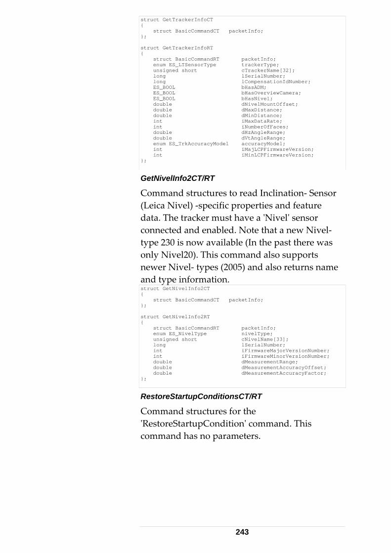
struct GetTrackerInfoCT { struct BasicCommandCT packetInfo; }; struct GetTrackerInfoRT { struct BasicCommandRT packetInfo; enum ES_LTSensorType trackerType; unsigned short cTrackerName[32]; long lSerialNumber; long lCompensationIdNumber; ES_BOOL bHasADM; ES_BOOL bHasOverviewCamera; ES_BOOL bHasNivel; double dNivelMountOffset; double dMaxDistance; double dMinDistance; int iMaxDataRate; int iNumberOfFaces; double dHzAngleRange; double dVtAngleRange; enum ES_TrkAccuracyModel accuracyModel; int iMajLCPFirmwareVersion; int iMinLCPFirmwareVersion; };
GetNivelInfo2CT/RT
Command structures to read Inclination‐ Sensor (Leica Nivel) ‐specific properties and feature data. The tracker must have a ʹNivelʹ sensor connected and enabled. Note that a new Nivel‐ type 230 is now available (In the past there was only Nivel20). This command also supports newer Nivel‐ types (2005) and also returns name and type information. struct GetNivelInfo2CT { struct BasicCommandCT packetInfo; }; struct GetNivelInfo2RT { struct BasicCommandRT packetInfo; enum ES_NivelType nivelType; unsigned short cNivelName[33]; long lSerialNumber; int iFirmwareMajorVersionNumber; int iFirmwareMinorVersionNumber; double dMeasurementRange; double dMeasurementAccuracyOffset; double dMeasurementAccuracyFactor; };
RestoreStartupConditionsCT/RT
Command structures for the ʹRestoreStartupConditionʹ command. This command has no parameters.
243
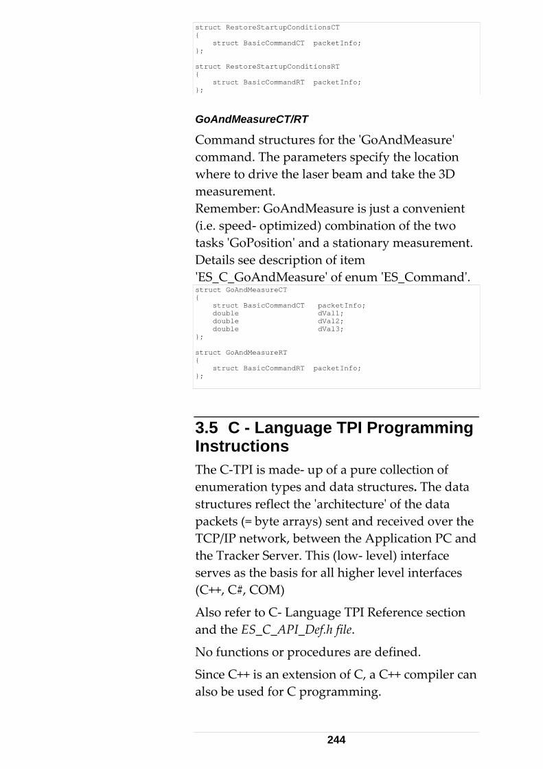
struct RestoreStartupConditionsCT { struct BasicCommandCT packetInfo; }; struct RestoreStartupConditionsRT { struct BasicCommandRT packetInfo; };
GoAndMeasureCT/RT
Command structures for the ʹGoAndMeasureʹ command. The parameters specify the location where to drive the laser beam and take the 3D measurement. Remember: GoAndMeasure is just a convenient (i.e. speed‐ optimized) combination of the two tasks ʹGoPositionʹ and a stationary measurement. Details see description of item ʹES_C_GoAndMeasureʹ of enum ʹES_Commandʹ. struct GoAndMeasureCT { struct BasicCommandCT packetInfo; double dVal1; double dVal2; double dVal3; }; struct GoAndMeasureRT { struct BasicCommandRT packetInfo; };
3.5 C - Language TPI Programming Instructions The C‐TPI is made‐ up of a pure collection of enumeration types and data structures. The data structures reflect the ʹarchitectureʹ of the data packets (= byte arrays) sent and received over the TCP/IP network, between the Application PC and the Tracker Server. This (low‐ level) interface serves as the basis for all higher level interfaces (C++, C#, COM)
Also refer to C‐ Language TPI Reference section and the ES_C_API_Def.h file.
No functions or procedures are defined.
Since C++ is an extension of C, a C++ compiler can also be used for C programming.
244
3.5.1 TCP/IP Connection 1. Establish a TCP/IP connection to the tracker server. This is typically achieved by invoking a Connect function of the TCP/IP communication library or toolbox. This function will take the IP address (or its related hostname) of your Tracker Server.
2. Set the TCP/IP Port Number to 700 for the Tracker Server. 3.5.2 Sending Commands 3. Call a SendData function from the TCP/IP communication library or toolbox (Function name may differ). This function typically takes a pointer to a data packet and probably the size of it (unless the packet is wrapped into a structure that knows its size implicitly, for example a Variant structure).
4. The architecture of the packets (TPI protocol) is defined by the data structures in the ES_C_API_Def.h file.
5. For invoking for example a GoPosition command, use the structure GoPositionCT and assign appropriate initialization values. In particular, assign an ES_Command and an ES_C_GoPosition as header‐ data and provide 3 coordinate values as command parameters. The compiler will not detect, if, for example, an ES_DT_SingleMeasResult as type, or an ES_C_SwitchLaser as command is assigned to a GoPositionCT variable. Inappropriate initialization values cause the command to fail.
GoPosition initialization sample:
245
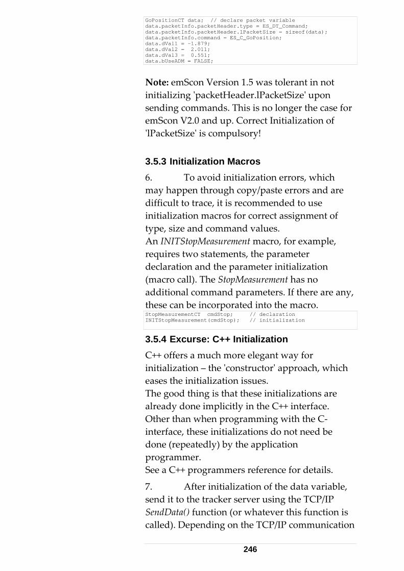
GoPositionCT data; // declare packet variable data.packetInfo.packetHeader.type = ES_DT_Command; data.packetInfo.packetHeader.lPacketSize = sizeof(data); data.packetInfo.command = ES_C_GoPosition; data.dVal1 = -1.879; data.dVal2 = 2.011; data.dVal3 = 0.551; data.bUseADM = FALSE;
Note: emScon Version 1.5 was tolerant in not initializing ʹpacketHeader.lPacketSizeʹ upon sending commands. This is no longer the case for emScon V2.0 and up. Correct Initialization of ʹlPacketSizeʹ is compulsory! 3.5.3 Initialization Macros 6. To avoid initialization errors, which may happen through copy/paste errors and are difficult to trace, it is recommended to use initialization macros for correct assignment of type, size and command values. An INITStopMeasurement macro, for example, requires two statements, the parameter declaration and the parameter initialization (macro call). The StopMeasurement has no additional command parameters. If there are any, these can be incorporated into the macro. StopMeasurementCT cmdStop; // declaration INITStopMeasurement(cmdStop); // initialization
3.5.4 Excurse: C++ Initialization C++ offers a much more elegant way for initialization – the ʹconstructorʹ approach, which eases the initialization issues. The good thing is that these initializations are already done implicitly in the C++ interface. Other than when programming with the C‐ interface, these initializations do not need be done (repeatedly) by the application programmer. See a C++ programmers reference for details.
7. After initialization of the data variable, send it to the tracker server using the TCP/IP SendData() function (or whatever this function is called). Depending on the TCP/IP communication
246
library used, the data packet may need to be packed into a Variant vrtData variable, followed by a SendData (vrtData) call. Alternatively, a Send() function takes the address and size of the data packet variable, Send (&data, sizeof(data)). 3.5.5 Answers from Tracker Server 8. The SendData() function does not wait for the Tracker Server (tracker) to complete the requested action ‐ SendData() will return immediately. On completion of the requested action, the tracker server sends an answer back to the client. Depending on the command, it may take a few seconds between sending the command and receiving an answer. This requires some type of notification or callback mechanism. That is, as soon as data arrives from the Tracker Server, some sort of event needs to trigger a ReadData() procedure in the client application. Depending on the TCP/IP communication, this notification could be a Windows Message, an Event or a Callback Function.
This type of communication is called asynchronous. 3.5.6 Asynchronous Communication 9. From the programmerʹs point of view, asynchronous communication is much more difficult to handle than synchronous communication. The programmer must ensure, not to send a new command until the answer of the previous one has returned. 3.5.7 DataArrived Notification 10. All TCP/IP communication libraries/toolkits contain either a DataArrived() notification or a similar function, which is called
247
by the framework each time data has arrived. Depending on the toolkit:
• The function may directly return a Variant type parameter that contains the data.
• The function may deliver the data within a byte array.
• The function returns the size of the data packet that is ready to be read. In this case, the DataArrived() function subsequently calls a ReadData() function immediately, in order to get the data into a local byte array.
3.5.8 Data arrival 'Traffic Jams' 11. If a ʹtraffic jamʹ occurs on the incoming TCP/IP line, i.e., if incoming data is being queued, a ReadData() call will read all the currently available data with no notification for each individual packet (supposed buffer is big enough). Many packets may be queued and only one DataArrived notification might be issued. This means that the byteArr buffer will contain more than one packet. This may occur on high frequency, continuous measurement streams. The application has to make provisions to correctly treat such cases. The lPacketSize value is most convenient when parsing the byteArr buffer. On the other hand, if the byteArr buffer is completely filled with data, it is likely that the last packet in the byteArr is incomplete. The packet fragment needs to be saved and padded to complete upon the subsequent read‐call.
See chapter ʹQueued and Scattered Dataʹ for details on how to properly treat such situations.
12. Assuming a received data block has been read into a byte buffer named byteArr. In order to interpret the data, a mask is required. This requires knowledge of the type of data packet (enum ES_DataType). A typical
248
PacketHeader interpreting code is as follows: 3.5.9 PacketHeader Masking PacketHeaderT *pData = (PacketHeaderT*)byteArr;
13. Type and the size of the packet can be accessed like: pData->type; pData->lPacketSize;
The packet size is only for convenience. Sizeof(data‐type) alternatively could be used to calculate the packet size.
This redundancy may be used for consistency checks and is helpful when using programming languages other than C that lack the sizeof() operator). From emScon Version 2.0 and up: lPacketSize must be initialized correctly also on sending packets. This information is essential and no longer ignored by the tracker server as this was the case for previous emScon server versions. 3.5.10 Command Subtype Switch 14. Command type answers require a switch statement to distinguish the command subtype. Non‐data returning commands can all be treated the same and are handled in the default switch statement. All other command answers need to be masked with the appropriate result structure. The code fragment below demonstrates this with the GetUnits command, and shows part of the handling of a single measurement answer:
249
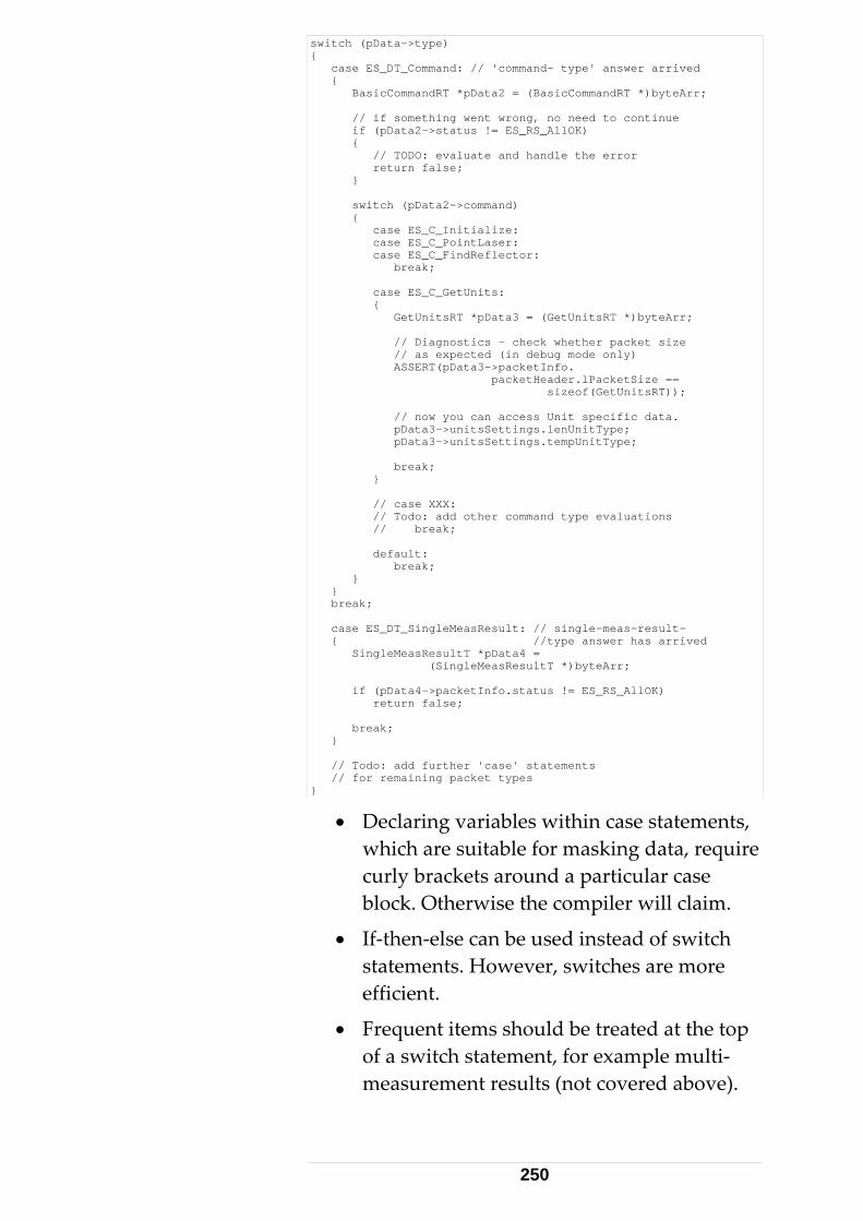
switch (pData->type) { case ES_DT_Command: // 'command- type' answer arrived { BasicCommandRT *pData2 = (BasicCommandRT *)byteArr; // if something went wrong, no need to continue if (pData2->status != ES_RS_AllOK) { // TODO: evaluate and handle the error return false; } switch (pData2->command) { case ES_C_Initialize: case ES_C_PointLaser: case ES_C_FindReflector: break; case ES_C_GetUnits: { GetUnitsRT *pData3 = (GetUnitsRT *)byteArr; // Diagnostics - check whether packet size // as expected (in debug mode only) ASSERT(pData3->packetInfo. packetHeader.lPacketSize == sizeof(GetUnitsRT)); // now you can access Unit specific data. pData3->unitsSettings.lenUnitType; pData3->unitsSettings.tempUnitType; break; } // case XXX: // Todo: add other command type evaluations // break; default: break; } } break; case ES_DT_SingleMeasResult: // single-meas-result- { //type answer has arrived SingleMeasResultT *pData4 = (SingleMeasResultT *)byteArr; if (pData4->packetInfo.status != ES_RS_AllOK) return false; break; } // Todo: add further 'case' statements // for remaining packet types }
• Declaring variables within case statements, which are suitable for masking data, require curly brackets around a particular case block. Otherwise the compiler will claim.
• If‐then‐else can be used instead of switch statements. However, switches are more efficient.
• Frequent items should be treated at the top of a switch statement, for example multi‐measurement results (not covered above).
250
3.6 C Language TPI - Samples Some older Samples distributed with former emScon versions have been dropped because they have ʹexpiredʹ. For Example Samples 1 and Sample 2 do no longer exist for the emScon V2.0 SDK. Nevertheless, the samples still provided have not been re‐named. Thatʹs the reason why Sample 3 is the first one referenced here. However, even if the names have not changed, the samples might have improved since earlier versions. Sample 4 (see C++ section) has been completely revised for example). Make sure to use the samples from the latest SDK version (i.e. the ones that match your current server‐ version) 3.6.1 Sample 3 Implements a ʹlightweightʹ C‐TPI client application, with no graphical interface, GUI overhead or MFC or ATL. This sample fits into a single file with about 350 lines of code (including comments and empty lines), and compiles into a small executable file.
This sample implements only Initialize Tracker and Get Direction commands. Since no Windows Message Loop is available, the application needs a multi‐threaded approach and therefore requires events and threads. For TCP/IP communication, the Winsock API functions are used. Further details see ʹReadme.txtʹ file in Sample 3 folder and code‐ comments in source files. Console Application
To create this or a similar sample from the scratch, the VC++ AppWizard or a text editor can
251
be used to create a ʹConsole Applicationʹ skeleton, and to implement the C standard entry function: int main(int argc, char* argv[]) { }
Add all the source code, save the file (.c or .cpp extension) and invoke the C compiler from the command line.
Comments
These comments refer to the file EmsyCApiConsoleClient.cpp.
The following include‐ files are required: #include <stdio.h> // standard C input/output #include <Winsock2.h> // win32 socket stuff #include <process.h> // thread stuff
• The main() function first does a TCP/IP connection by calling the function TcpIpConnect(), starts the Data Receiver thread and enters an endless ʹUser Interface loopʹ. The default IP address “192.168.0.1” should be adjusted to the actual server address. Alternatively, the IP address can be passed as command‐ line argument upon running the application.
• This loop looks for user input of one of the two TPI commands ʹiʹ for Initialize Tracker and ʹgʹ for Get Direction.
• If the user enters x, the loop is stopped, the TCP/IP connection is closed and the application terminates. The TcpIpConnect() function is straightforward up to the call of connect().
• Call WSAStartup. After connecting, call WSAEventSelect(), which takes the following parameters:
‐ A socket handle (that has been created before) as a global variable.
‐ An event of type WSAEVENT as a global variable. This variable must be initialized
252
with the return value of a WSACreateEvent() call.
‐ A flags parameter. FD_READ is passed, indicating an interest in data‐arrival events (a realistic application would have to also trap FD_CLOSE events).
Calling this function will cause the TCP/IP framework to signal the passed event, whenever data has arrived at the socket.
The DataRecvThread() has an infinite loop with the following statement:
WaitForSingleObject(g_hSocketEvent, INFINITE);
This is a blocking call and causes the loop to stop, until the event is signaled to be read. The blocking by the WaitForSingleObject is released and the loop passes on.
Reset the event before available data is read into a buffer.
Call a function ProcessData() that does the interpretation of the buffer.
Queuing (Traffic Jams)
There are no provisions to handle ʹtraffic jamsʹ on the network. A real application needs to make provisions to handle such situations with a packet size transmitted in the header of each packet. The Winsock function setsockopt() may be used to ʹtuneʹ TCP/IP transmission rate by increasing buffer sizes.
See Win32 documentation for more information about Winsock API (especially the WSA… function), threads and events.
See also ʹSample 9ʹ (Receiving Data) in the C++ TPI section. Notice the comments in the source code.
253
Remarks
This sample can easily be ported to non‐Win32 platforms (Unix, Linux, and Mac).
Creating a ʹconsoleʹ application requires the use of the WSAEventSelect() function with events and threads. Excurse: Windows Application
This chapter points out the options we had if we chosen a Windows application instead of a Console application.
For Windows applications, the WSAAsyncSelect() function would be more appropriate. It issues Window messages instead of events, which are simpler to handle. No separate thread is required (the window message loop takes this part).
See Win32 documentation on WSAAsyncSelect().
Winsock API
In Windows applications, the Winsock Active X control (MSWinsck.ocx) could be used instead of the Winsock2 API. This especially applies to VB / VBA applications. The Winsock Active X control provides a very high abstraction of socket‐ commuiation and thus is quite easy to use. For C++ applications, the use of a MFC library permits a very convenient class wrapper around the Winsock2 API.
Refer to the CAsyncSocket and CSocket classes in C++ section for details. Attention: The MFC ʹCSocketʹ class may cause problems when transferring very high rated amounts of data (High frequency continuous measurements). See Sample4/Step5 and Step6 (ReadmeStep5.txt / ReadmeStep6.txt) files for details and how to avoid these problems.
254
4 C++ Interface
4.1 Class- based TPI Programming 4.1.1 Preconditions Using the C++ interface requires sufficient knowledge of object‐ oriented programming. A programmer should at least know about class‐ design, class‐ inheritance, virtual functions, member function overloads, asynchronous programming concepts and TCP/IP socket programming.
This chapter describes wrapper‐classes for data structures and two main classes used for sending commands and receiving answers.
The description of the classes in this chapter may be slightly discrepant to the contents of the ES_CPP_API_Def.h file in the SDK. In case of discrepancies, the information in the ES_CPP_API_Def.h file should be regarded as correct.
Sample 4 (former Sample 4_2 in emScon 1.5) comprises all these topics. This sample is most suitable for introduction into emScon C++ programming.
The C++ TPI does not provide any additional functions for the Tracker Server. It is built upon the C‐ interface and is made up of one include file, ES_CPP_API_Def.h with ES_C_API_Def.h as its basis. The C++ interface implements two classes CESAPICommand and CESAPIReceive, apart from wrapper classes for each data structure (of the C‐TPI).
255
CESAPICommand handles sending of commands from the client application to the Tracker server and CESAPIReceive supports receiving and parsing data sent by the Tracker Server back to the client application.
The advantage of a class design is the availability of constructors to perform (struct) initialization. Using the TPI C++ interface is preferable to the C‐ low‐level (native) interface, if a C++ compiler is available. 4.1.2 Platform Issues Tracker Server client programming remains platform independent since C++ compilers are available for virtually every platform. 4.1.3 TCP/IP This chapter does not touch TCP/IP basic issues. See C‐ TPI section since this topic is independent from the interface‐ type used (except COM interface, where communication is embedded)
4.2 C++ Language TPI Reference 4.2.1 CESAPICommand class SendPacket virtual bool SendPacket(void* PacketStart, long PacketSize);
This is a pure virtual function that must be implemented in the class derived from CESAPICommand. Its implementation depends on the selected TCP/IP socket library / API. Command Functions
Only a few sample of the classʹ command member functions are listed here since these can be derived directly from the C‐ interface.
256
Example for a command taking no parameters (Initialize the tracker): bool Initialize();
Example for a command taking basic‐ type parameters: bool SetContinuousTimeModeParams(long lTimeSeparation, long lNumberOfPoints, bool bUseRegion, ES_RegionType regionType);
Example for a command taking a struct parameter: bool SetContinuousTimeModeParams(ContinuousTimeModeDataT continuousTimeModeData);
The latter two functions are different overloads of the same function.
Many of the command‐ functions exist in two different overloads. Depending on context, it may be more suitable for an application to use one or the other overload.
A complete listing of all these functions is available from the CESAPICommand class definition in the file ʹES_CPP_API_Def.hʹ file.
Rather than redundantly listing all of these member functions in this chapter, a general rule is presented on how to derive the function names from the related C‐TPI structures. (The text in [brackets] shows the rule applied to a sample).
• Look up the command of interest in the ʹenum ES_Commandʹ (C‐ TPI Reference). [ES_C_SetContinuousTimeModeParams]
• Remove the prefix ʹES_C_ʹ from the command tag‐ name. This will be the name of the C++ function. [SetContinuousTimeModeParams ()]
• For finding the input parameters, add the Postfix ʹCTʹ to the remaining command‐ tag
257
name. [SetContinuousTimeModeParamsCT].
• Look up this CT structure in the C‐ TPI reference for a description of all the parameters.
4.2.2 CESAPIReceive class ReceiveData bool ReceiveData(void* packetStart, long packetSize);
ReceiveData is the parser‐ function for incoming data. It has to be called after receiving a block of data from the emScon server.
Packets passed to this method must be COMPLETE (in terms of an RT struct as defined in the C‐API). Packet fragments are not processed correctly. Hence the application (which calls ReceiveData) must ensure to pass complete packets. See chapter ʹQueued and Scattered Dataʹ for details. Data Arrival virtual Functions
The principle is as follows: Derive your own class from CESAPIReceive and override those virtual functions on whose data you are interested in.
Only a few sample of the classʹ virtual data receiver member functions are listed here since these can be derived directly from the C‐ interface.
Example for a command that does not return any data. If this function is called this means the command has successfully executed ( i.e. the tracker has finished initializing): virtual void OnInitializeAnswer();
Example for a command returning data. (Which is the case for all ʹGet...ʹ functions).
258
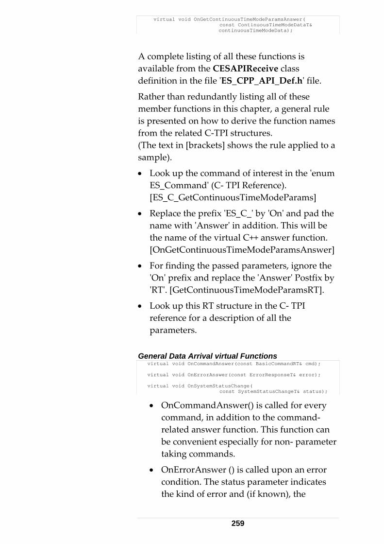
virtual void OnGetContinuousTimeModeParamsAnswer( const ContinuousTimeModeDataT& continuousTimeModeData);
A complete listing of all these functions is available from the CESAPIReceive class definition in the file ʹES_CPP_API_Def.hʹ file.
Rather than redundantly listing all of these member functions in this chapter, a general rule is presented on how to derive the function names from the related C‐TPI structures. (The text in [brackets] shows the rule applied to a sample).
• Look up the command of interest in the ʹenum ES_Commandʹ (C‐ TPI Reference). [ES_C_GetContinuousTimeModeParams]
• Replace the prefix ʹES_C_ʹ by ʹOnʹ and pad the name with ʹAnswerʹ in addition. This will be the name of the virtual C++ answer function. [OnGetContinuousTimeModeParamsAnswer]
• For finding the passed parameters, ignore the ʹOnʹ prefix and replace the ʹAnswerʹ Postfix by ʹRTʹ. [GetContinuousTimeModeParamsRT].
• Look up this RT structure in the C‐ TPI reference for a description of all the parameters.
General Data Arrival virtual Functions virtual void OnCommandAnswer(const BasicCommandRT& cmd); virtual void OnErrorAnswer(const ErrorResponseT& error); virtual void OnSystemStatusChange( const SystemStatusChangeT& status);
• OnCommandAnswer() is called for every command, in addition to the command‐ related answer function. This function can be convenient especially for non‐ parameter taking commands.
• OnErrorAnswer () is called upon an error condition. The status parameter indicates the kind of error and (if known), the
259
command parameter indicates the command that caused the error. Note that not all errors are caused through commands (e.g. Beam broken). In such cases, the command parameter is ʹunknownʹ. For status values, see enum ʹES_ResultStatusʹ and error numbers in the Appendix of this manual
• OnSystemStatusChange() is called for every status change event. For status values, see enum ʹES_SystemStatusChangeʹ
Note that virtual functions are only called if defined int the derived receiver class. Particular arrival data can be ignored if the appropriate virtual function definition is omitted.
Attention: Make sure the signature of the virtual function in the derived class exactly matches the signature in ʹCESAPIReceiveʹ. However, the keyword ʹvirtualʹ is optional in the derived class.
Mismatching signatures will result in not calling the functions. The compiler cannot detect such kind of errors.
It is therefore recommended to copy/paste the virtual function header from CESAPIReceive to the derived class.
4.3 C++ Language TPI Programming Instructions 4.3.1 Sending Data The class CESAPICommand contains a virtual function SendPacket(), which must be overwritten. This approach allows convenient ʹSend…ʹ command functions.
260
Dealing with C data structures for sending commands is no longer required, as they are completely ʹhiddenʹ. Use the related member functions of CESAPICommand instead. 4.3.2 Receiving Data In order to select the data the application is interested in, CESAPIReceive offers a method ReceiveData, which is called on data arrival events, as well as numerous virtual member functions..
Dealing with C data structures for receiving data is no longer required, as they are completely ʹhiddenʹ. Use the related (virtual) member functions of CESAPIReceive instead. 4.3.3 Class Design Issues All class member functions are defined ʹinlineʹ. Neither a library nor a .cpp file is required. One single include file makes up the C++ interface. The C++ interface is thus fully transparent with complete source code provided.
The C++ interface implements two classes named CESAPICommand and CESAPIReceive, apart from wrapper classes for each data structure (of the C‐ TPI). A class design has the advantage of constructors to delegate initialization issues. The class CESAPICommand has a virtual function, SendPacket(), which must be overwritten using Send… command functions.
While the CESAPICommand class is used to send data to the tracker server, the class CESAPIReceive is used to receive data.
The principle is as follows: Derive your own class from CESAPIReceive class and override those virtual functions on whose data you are
261
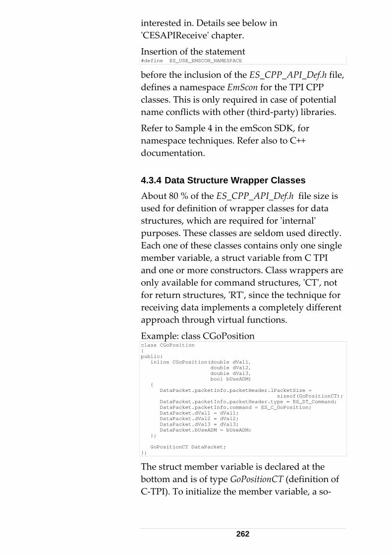
interested in. Details see below in ʹCESAPIReceiveʹ chapter.
Insertion of the statement #define ES_USE_EMSCON_NAMESPACE
before the inclusion of the ES_CPP_API_Def.h file, defines a namespace EmScon for the TPI CPP classes. This is only required in case of potential name conflicts with other (third‐party) libraries.
Refer to Sample 4 in the emScon SDK, for namespace techniques. Refer also to C++ documentation. 4.3.4 Data Structure Wrapper Classes About 80 % of the ES_CPP_API_Def.h file size is used for definition of wrapper classes for data structures, which are required for ʹinternalʹ purposes. These classes are seldom used directly. Each one of these classes contains only one single member variable, a struct variable from C TPI and one or more constructors. Class wrappers are only available for command structures, ʹCTʹ, not for return structures, ʹRTʹ, since the technique for receiving data implements a completely different approach through virtual functions.
Example: class CGoPosition class CGoPosition { public: inline CGoPosition(double dVal1, double dVal2, double dVal3, bool bUseADM) { DataPacket.packetInfo.packetHeader.lPacketSize = sizeof(GoPositionCT); DataPacket.packetInfo.packetHeader.type = ES_DT_Command; DataPacket.packetInfo.command = ES_C_GoPosition; DataPacket.dVal1 = dVal1; DataPacket.dVal2 = dVal2; DataPacket.dVal3 = dVal3; DataPacket.bUseADM = bUseADM; }; GoPositionCT DataPacket; };
The struct member variable is declared at the bottom and is of type GoPositionCT (definition of C‐TPI). To initialize the member variable, a so‐
262
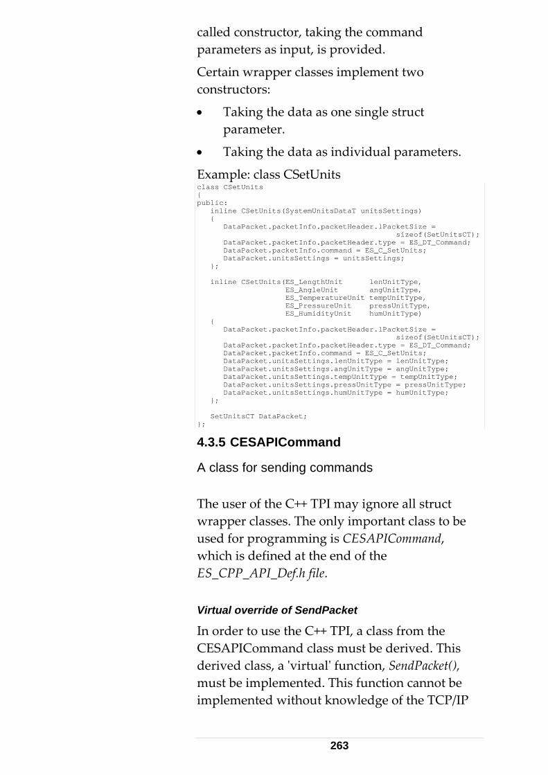
called constructor, taking the command parameters as input, is provided.
Certain wrapper classes implement two constructors:
• Taking the data as one single struct parameter.
• Taking the data as individual parameters.
Example: class CSetUnits class CSetUnits { public: inline CSetUnits(SystemUnitsDataT unitsSettings) { DataPacket.packetInfo.packetHeader.lPacketSize = sizeof(SetUnitsCT); DataPacket.packetInfo.packetHeader.type = ES_DT_Command; DataPacket.packetInfo.command = ES_C_SetUnits; DataPacket.unitsSettings = unitsSettings; }; inline CSetUnits(ES_LengthUnit lenUnitType, ES_AngleUnit angUnitType, ES_TemperatureUnit tempUnitType, ES_PressureUnit pressUnitType, ES_HumidityUnit humUnitType) { DataPacket.packetInfo.packetHeader.lPacketSize = sizeof(SetUnitsCT); DataPacket.packetInfo.packetHeader.type = ES_DT_Command; DataPacket.packetInfo.command = ES_C_SetUnits; DataPacket.unitsSettings.lenUnitType = lenUnitType; DataPacket.unitsSettings.angUnitType = angUnitType; DataPacket.unitsSettings.tempUnitType = tempUnitType; DataPacket.unitsSettings.pressUnitType = pressUnitType; DataPacket.unitsSettings.humUnitType = humUnitType; }; SetUnitsCT DataPacket; };
4.3.5 CESAPICommand
A class for sending commands
The user of the C++ TPI may ignore all struct wrapper classes. The only important class to be used for programming is CESAPICommand, which is defined at the end of the ES_CPP_API_Def.h file. Virtual override of SendPacket
In order to use the C++ TPI, a class from the CESAPICommand class must be derived. This derived class, a ʹvirtualʹ function, SendPacket(), must be implemented. This function cannot be implemented without knowledge of the TCP/IP
263
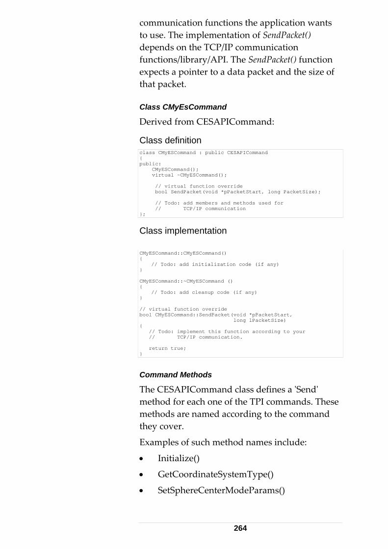
communication functions the application wants to use. The implementation of SendPacket() depends on the TCP/IP communication functions/library/API. The SendPacket() function expects a pointer to a data packet and the size of that packet. Class CMyEsCommand
Derived from CESAPICommand:
Class definition class CMyESCommand : public CESAPICommand { public: CMyESCommand(); virtual ~CMyESCommand(); // virtual function override bool SendPacket(void *pPacketStart, long PacketSize); // Todo: add members and methods used for // TCP/IP communication };
Class implementation CMyESCommand::CMyESCommand() { // Todo: add initialization code (if any) } CMyESCommand::~CMyESCommand () { // Todo: add cleanup code (if any) } // virtual function override bool CMyESCommand::SendPacket(void *pPacketStart, long lPacketSize) { // Todo: implement this function according to your // TCP/IP communication. return true; }
Command Methods
The CESAPICommand class defines a ʹSendʹ method for each one of the TPI commands. These methods are named according to the command they cover.
Examples of such method names include:
• Initialize()
• GetCoordinateSystemType()
• SetSphereCenterModeParams()
264
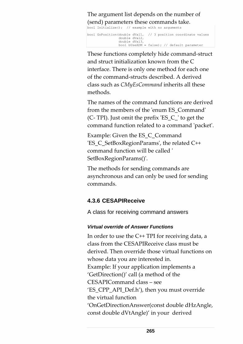
The argument list depends on the number of (send) parameters these commands take. bool Initialize(); // example with no arguments bool GoPosition(double dVal1, // 3 position coordinate values double dVal2, double dVal3, bool bUseADM = false); // default parameter
These functions completely hide command‐struct and struct initialization known from the C interface. There is only one method for each one of the command‐structs described. A derived class such as CMyEsCommand inherits all these methods.
The names of the command functions are derived from the members of the ʹenum ES_Commandʹ (C‐ TPI). Just omit the prefix ʹES_C_ʹ to get the command function related to a command ʹpacketʹ.
Example: Given the ES_C_Command ʹES_C_SetBoxRegionParamsʹ, the related C++ command function will be called ʹ SetBoxRegionParams()ʹ.
The methods for sending commands are asynchronous and can only be used for sending commands. 4.3.6 CESAPIReceive
A class for receiving command answers Virtual override of Answer Functions
In order to use the C++ TPI for receiving data, a class from the CESAPIReceive class must be derived. Then override those virtual functions on whose data you are interested in. Example: If your application implements a ‘GetDirection()’ call (a method of the CESAPICommand class – see ‘ES_CPP_API_Def.h’), then you must override the virtual function ‘OnGetDirectionAnswer(const double dHzAngle, const double dVtAngle)’ in your derived
265
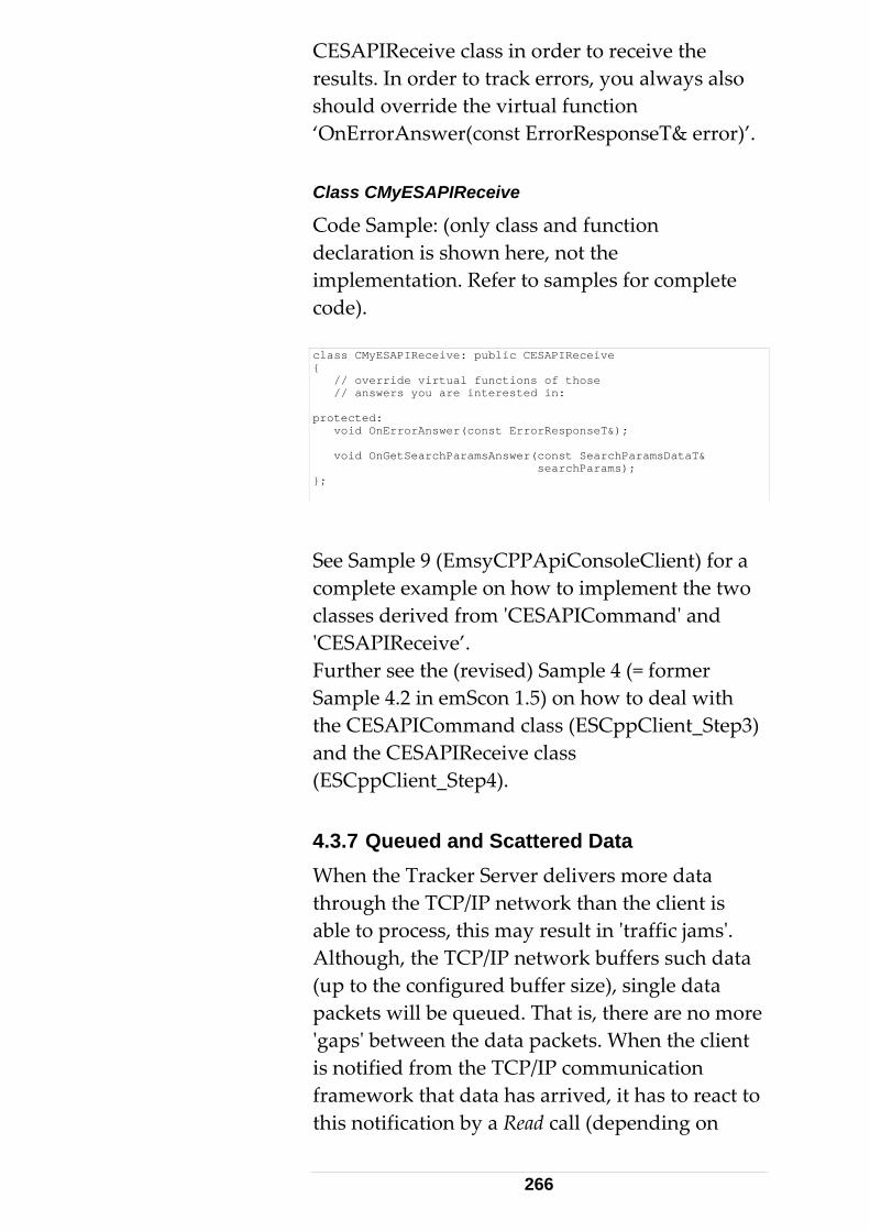
CESAPIReceive class in order to receive the results. In order to track errors, you always also should override the virtual function ‘OnErrorAnswer(const ErrorResponseT& error)’. Class CMyESAPIReceive
Code Sample: (only class and function declaration is shown here, not the implementation. Refer to samples for complete code). class CMyESAPIReceive: public CESAPIReceive { // override virtual functions of those // answers you are interested in: protected: void OnErrorAnswer(const ErrorResponseT&); void OnGetSearchParamsAnswer(const SearchParamsDataT& searchParams); };
See Sample 9 (EmsyCPPApiConsoleClient) for a complete example on how to implement the two classes derived from ʹCESAPICommandʹ and ʹCESAPIReceive’. Further see the (revised) Sample 4 (= former Sample 4.2 in emScon 1.5) on how to deal with the CESAPICommand class (ESCppClient_Step3) and the CESAPIReceive class (ESCppClient_Step4). 4.3.7 Queued and Scattered Data When the Tracker Server delivers more data through the TCP/IP network than the client is able to process, this may result in ʹtraffic jamsʹ. Although, the TCP/IP network buffers such data (up to the configured buffer size), single data packets will be queued. That is, there are no more ʹgapsʹ between the data packets. When the client is notified from the TCP/IP communication framework that data has arrived, it has to react to this notification by a Read call (depending on
266
your communication tools, this can be recv, GetData, CSocket::Receive() etc.).
These read functions are not able to recognize packet boundaries. Read functions read all data that is currently available (In practice, the data will be read in one read‐ cycle, only limited to current buffer size).
Thus the buffer may now contain several congested packets. The other special case is if there is only a fraction of a packet . Problem Solution There are several possible approaches:
• Provide a sufficient read‐buffer and read all that is currently pending. The client application parses the data block into packets, using the header information and size of each packet. With a fragmented last packet, the next read‐ cycle is started and the two fragments from the previous and the current reading are assembled together. This is probably the most efficient method, since it minimizes the number of reading interrupts. However, it is also the most complex one in terms of data parsing.
• Read only the first 4 Bytes to determine the size of the first pending packet. The rest of the packet is estimated by reading (packetSize – 4) bytes. Alternate method: ʹPeekʹ (instead of Read) the packet‐size, without removing data from the socket. With known size, read as many bytes as indicated by packetSize. See code sample below. This is the method we propagate for all our samples. Note: Earlier versions of the Samples /
267
Manual (up to emScon 2.3.472) propagated to peek the full packet‐header (8 bytes). In the meantime, the very seldom situation that a packet boundary ran across the middle of a packet header was encountered indeed! That is, the first part (4 Bytes) of the header (of the next packet) is at the tail of the current packet. Hence, we failed to peek the header for 8 bytes. Only 4 bytes were returned. To avoid such (although rare!) problems, the function was revised in terms it now only peeks for the packet‐size (the first 4 Bytes).
The sample code shown below demonstrates a method to ensure complete packets (if data blocks arrive scattered) and to avoid data congestion (traffic jams). It is based on Winsock 2.0 API functions. Remember: There exist other approaches to implement safe socket reading. Indeed, in terms of performance, Peeking and then Reading may not be the best solution. However, itʹs probably the easiest one to implement. A most performing algorithm would probably always read all data that is currently pending and then parse the data on the application side. However, such an approach is much more complex.
268
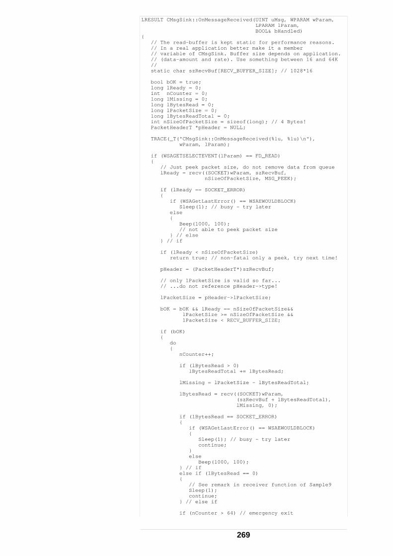
LRESULT CMsgSink::OnMessageReceived(UINT uMsg, WPARAM wParam, LPARAM lParam, BOOL& bHandled) { // The read-buffer is kept static for performance reasons. // In a real application better make it a member // variable of CMsgSink. Buffer size depends on application. // (data-amount and rate). Use something between 16 and 64K // static char szRecvBuf[RECV_BUFFER_SIZE]; // 1028*16 bool bOK = true; long lReady = 0; int nCounter = 0; long lMissing = 0; long lBytesRead = 0; long lPacketSize = 0; long lBytesReadTotal = 0; int nSizeOfPacketSize = sizeof(long); // 4 Bytes! PacketHeaderT *pHeader = NULL; TRACE(_T("CMsgSink::OnMessageReceived(%lu, %lu)\n"), wParam, lParam); if (WSAGETSELECTEVENT(lParam) == FD_READ) { // Just peek packet size, do not remove data from queue lReady = recv((SOCKET)wParam, szRecvBuf, nSizeOfPacketSize, MSG_PEEK); if (lReady == SOCKET_ERROR) { if (WSAGetLastError() == WSAEWOULDBLOCK) Sleep(1); // busy - try later else { Beep(1000, 100); // not able to peek packet size } // else } // if if (lReady < nSizeOfPacketSize) return true; // non-fatal only a peek, try next time! pHeader = (PacketHeaderT*)szRecvBuf; // only lPacketSize is valid so far... // ...do not reference pHeader->type! lPacketSize = pHeader->lPacketSize; bOK = bOK && lReady == nSizeOfPacketSize&& lPacketSize >= nSizeOfPacketSize && lPacketSize < RECV_BUFFER_SIZE; if (bOK) { do { nCounter++; if (lBytesRead > 0) lBytesReadTotal += lBytesRead; lMissing = lPacketSize - lBytesReadTotal; lBytesRead = recv((SOCKET)wParam, (szRecvBuf + lBytesReadTotal), lMissing, 0); if (lBytesRead == SOCKET_ERROR) { if (WSAGetLastError() == WSAEWOULDBLOCK) { Sleep(1); // busy - try later continue; } else Beep(1000, 100); } // if else if (lBytesRead == 0) { // See remark in receiver function of Sample9 Sleep(1); continue; } // else if if (nCounter > 64) // emergency exit
269
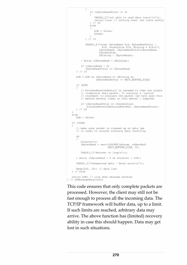
{ if (lBytesReadTotal <= 0) { TRACE(_T("not able to read data (recv)\n")); return true; // nothing read, can leave safely } // if else { bOK = false; break; } } // if TRACE(_T("Loop: BytesRead %ld, BytesReadTotal \ %ld, PacketSize %ld, Missing = %ld\n"), lBytesRead, lBytesReadTotal+lBytesRead, lPacketSize, lMissing - lBytesRead); } while (lBytesRead < lMissing); if (lBytesRead > 0) lBytesReadTotal += lBytesRead; } // if bOK = bOK && lBytesRead == lMissing && lBytesReadTotal <= RECV_BUFFER_SIZE; if (bOK) { // ProcessReceivedData() is assumed to take one single // (complete) data packet. It contains a 'switch' // statement to evaluate the packet (we have seen this // method several times in this manual / samples) if (lBytesReadTotal == lPacketSize) ProcessReceivedData(szRecvBuf, lBytesReadTotal); } // if } else bOK = false; if (!bOK) { // make sure socket is cleaned up on data jam // in order to recover ordinary data receiving do { nCounter++; lBytesRead = recv((SOCKET)wParam, szRecvBuf, RECV_BUFFER_SIZE, 0); TRACE(_T("Recover in loop\n")); } while (lBytesRead > 0 && nCounter < 128); TRACE(_T("Unexpected data - fatal error\n")); Beep(250, 10); // data lost } // else return bOK; // true when message handled } // OnMessageReceived()
This code ensures that only complete packets are processed. However, the client may still not be fast enough to process all the incoming data. The TCP/IP framework will buffer data, up to a limit. If such limits are reached, arbitrary data may arrive. The above function has (limited) recovery ability in case this should happen. Data may get lost in such situations.
270
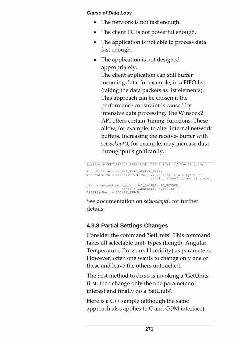
Cause of Data Loss
• The network is not fast enough.
• The client PC is not powerful enough.
• The application is not able to process data fast enough.
• The application is not designed appropriately. The client application can still buffer incoming data, for example, in a FIFO list (taking the data packets as list elements). This approach can be chosen if the performance constraint is caused by intensive data processing. The Winsock2 API offers certain ʹtuningʹ functions. These allow, for example, to alter internal network buffers. Increasing the receive‐ buffer with setsockopt(), for example, may increase data throughput significantly.
#define SOCKET_READ_BUFFER_SIZE (256 * 1024) // 256 KB buffer int nBufSize = SOCKET_READ_BUFFER_SIZE; int nVarSize = sizeof(nBufSize); // we know it's 4 byte, but //using sizeof is better style! nRet = setsockopt(m_sock, SOL_SOCKET, SO_RCVBUF, (char *)&nBufSize, nVarSize); ASSERT(nRet != SOCKET_ERROR);
See documentation on setsockopt() for further details. 4.3.8 Partial Settings Changes Consider the command ʹSetUnitsʹ. This command takes all selectable unit‐ types (Length, Angular, Temperature, Pressure, Humidity) as parameters. However, often one wants to change only one of these and leave the others untouched.
The best method to do so is invoking a ʹGetUnitsʹ first, then change only the one parameter of interest and finally do a ʹSetUnitsʹ.
Here is a C++ sample (although the same approach also applies to C and COM interface).
271
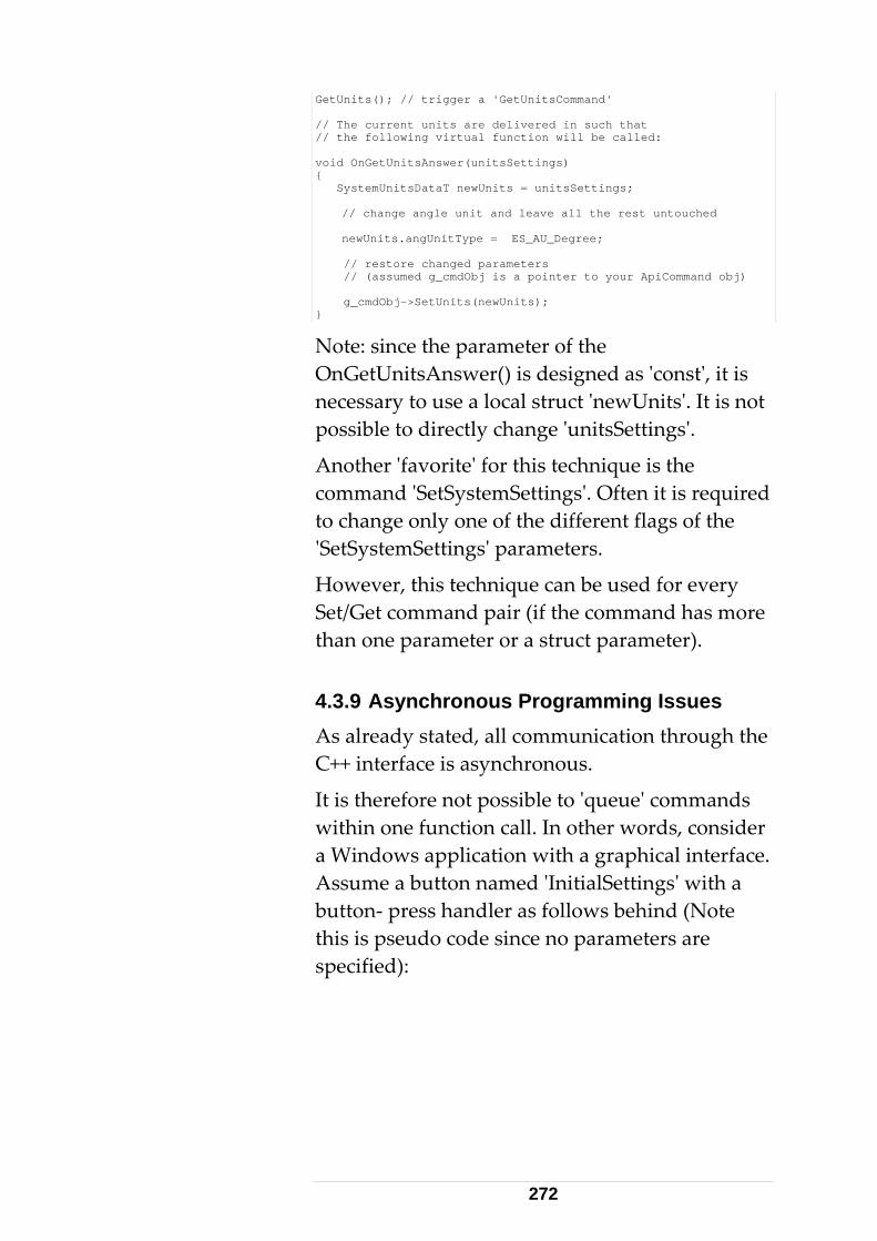
GetUnits(); // trigger a 'GetUnitsCommand' // The current units are delivered in such that // the following virtual function will be called: void OnGetUnitsAnswer(unitsSettings) { SystemUnitsDataT newUnits = unitsSettings; // change angle unit and leave all the rest untouched newUnits.angUnitType = ES_AU_Degree; // restore changed parameters // (assumed g_cmdObj is a pointer to your ApiCommand obj) g_cmdObj->SetUnits(newUnits); }
Note: since the parameter of the OnGetUnitsAnswer() is designed as ʹconstʹ, it is necessary to use a local struct ʹnewUnitsʹ. It is not possible to directly change ʹunitsSettingsʹ.
Another ʹfavoriteʹ for this technique is the command ʹSetSystemSettingsʹ. Often it is required to change only one of the different flags of the ʹSetSystemSettingsʹ parameters.
However, this technique can be used for every Set/Get command pair (if the command has more than one parameter or a struct parameter). 4.3.9 Asynchronous Programming Issues As already stated, all communication through the C++ interface is asynchronous.
It is therefore not possible to ʹqueueʹ commands within one function call. In other words, consider a Windows application with a graphical interface. Assume a button named ʹInitialSettingsʹ with a button‐ press handler as follows behind (Note this is pseudo code since no parameters are specified):
272
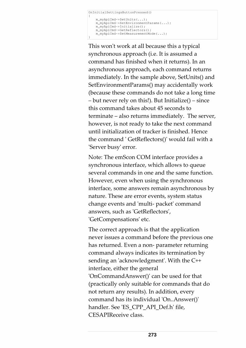
OnInitialSettingsButtonPressed() { m_myApiCmd->SetUnits(...); m_myApiCmd->SetEnvironmentParams(...); m_myApiCmd->Initialize(); m_myApiCmd->GetReflectors(); m_myApiCmd->SetMeasurementMode(...); }
This wonʹt work at all because this a typical synchronous approach (i.e. It is assumed a command has finished when it returns). In an asynchronous approach, each command returns immediately. In the sample above, SetUnits() and SetEnvironmentParams() may accidentally work (because these commands do not take a long time – but never rely on this!). But Initialize() – since this command takes about 45 seconds to terminate – also returns immediately. The server, however, is not ready to take the next command until initialization of tracker is finished. Hence the command ʹ GetReflectors()ʹ would fail with a ʹServer busyʹ error.
Note: The emScon COM interface provides a synchronous interface, which allows to queue several commands in one and the same function. However, even when using the synchronous interface, some answers remain asynchronous by nature. These are error events, system status change events and ʹmulti‐ packetʹ command answers, such as ʹGetReflectorsʹ, ʹGetCompensationsʹ etc.
The correct approach is that the application never issues a command before the previous one has returned. Even a non‐ parameter returning command always indicates its termination by sending an ʹacknowledgmentʹ. With the C++ interface, either the general ʹOnCommandAnswer()ʹ can be used for that (practically only suitable for commands that do not return any results). In addition, every command has its individual ʹOn..Answer()ʹ handler. See ʹES_CPP_API_Def.hʹ file, CESAPIReceive class.
273
In particular, the next command may not be issued before the ʹOn..Answer()ʹ handler of the previous command has arrived. There are several possible approaches to achieve correct execution of a series of commands :
• Directly call the next command in the ʹOn..Answer()ʹ of the previous command. This approach is demonstrated with the ʹGetReflectorsʹ / ʹGetReflector()ʹ sequence in Step4 of Sample 4. Remark: There is a helper function InitReflectorBox() in OnGetReflectorsAnswer(). The next command ʹ GetReflector()ʹ is called in this ʹInitReflectorBox()ʹ function. However, ʹGetReflector()ʹ could also be called inside ʹOnGetReflectorsAnswer()ʹ function directly.
• Queue your commands in a list. Take the first command from the list and send it to the tracker server. At the same time, set an Event (or another synchronization object, such as Mutex or Semaphore)ʹ that prevents taking the next command from the list. As soon as the answer of the pending command arrives, reset the Event, which will cause to process the next command from the list. In contrast to the first approach, where each On..Answer() handler calls a different subsequent command, this second approach is more general in such that every answer handler does the same: ʹResetEventʹ. Needless to say that this approach means a multi threaded application.
• Queue your commands in a list. Use an application‐defined Windows message handler that removes and processes the first command of the list and sends it to the
274
tracker server. To start the ʹcommand‐ chainʹ, do an explicit first call of this message handler. In every ʹOn..Answer()ʹ handler, a ʹPostMessage()ʹ call will cause to trigger the message handler in order to process the next command. (Important to use PostMessage, not SendMessage). The advantage of this approach is that no multi‐ threaded application is required since the Windows message loop takes care of synchronization. On the other hand, this approach only works for windows applications and not for console applications or ʹwindowless server applicationsʹ (Hint: you may use an invisible window for message handling).
• To be complete, the most simple approach is also mentioned here, although this does not really mean an ʹautomated queuingʹ of commands: Let the synchronization to the user! This means that the application implements an individual Button for every command, i.e. every button handler calls only one command. The user himself must make sure he does not press a button while a pending command has not terminated. The application can support the user in such that it disables all buttons while a command is in action. (Disable all buttons when pressing any button, enable all again when a ʹOn..Answer()ʹ handler is called).
The ʹasynchronous issuesʹ of this chapter also apply to the C‐ Interface and the emScon COM interface – as far as using the asynchronous interface (or those parts of the synchronous COM interface that remain asynchronous by nature).
275
4.3.10 Working with multiple trackers Under C/C++ context, there is nothing special to say about addressing multiple trackers from within one application. Just ʹduplicateʹ the code from the first tracker to set up a 2nd connection to a different controller/tracker. For the C++ interface, this means to create 2nd instances of the ʹCESApiCommandʹ and ʹCESApiReceiveʹ ‐ derived classes. Remarks: If instances of the same Command‐ (= Sender) and Receiver‐ classes are being used for both trackers, these classes must not contain global or shared! In particular, make sure any instance gets its own instance of a communication socket (for example by passing the socket objects through constructor variables to the Sender/Receiver classes). Note that the Command‐ and Receiver‐ classes used in the provided SDK Samples (7, 9) do not consequently follow these principles! Especially socket objects are global or shared. You must either modify these classes in order to make them ʹmulti‐ instantiableʹ, or use a ʹcopy/pasteʹ approach and setup different Send/Receiver classes for the 2nd tracker. The latter means duplicated code and should be avoided ‐ unless both trackers have to fulfill completely different tasks that require a different set of commands and event handlers. The former (using multiple instances of one and the same Sender/Receiver class for multiple trackers) in addition may require introducing a ʹcookieʹ‐ property to the Receiver class. This can be just an integer (tracker# 1 or 2), which is passed as a parameter to the constructor. Upon receiving answers, this cookie can then be used to identify whether the answer came from the first or from the 2nd tracker. Otherwise there would
276
be no way to identify whether an even handler was triggered from one or the other tracker (consider that both trackers may perform the same command at the same time!). An alternative (and from object oriented point of view much better) approach than using cookies is to pass a reference of the sender object to the Receiver class. That is, instead of (or in addition to) passing a cookie, we directly pass the MyAPICommand variable. This approach is suitable if both trackers have to do the same sequence of commands. Otherwise, we may need the cookie nevertheless in addition to the command object reference. See also chapter ʹMulti Tracker C# Applicationsʹ in section 6; there is a (C#) code‐ sample demonstrating the cookie‐ technique. This sample also shows how to make Sender/Receiver classes ʹmulti‐instantiableʹ ‐ the shown approach there (sockets, command objects, and cookies passed through constructor variables) can easily be equivalently applied to C++ applications. Threading Issues: All calls to the C++ interface are asynchronous by design; it is therefore NOT required, nor recommended to use multi‐threading, i.e. running the two tracker instances in two different threads (although ‐ depending on your application design ‐ there might be reasons to do so nevertheless). A (Windows) application will be able to address both trackers in ʹparallelʹ without dealing with the complexity of multiple threads. However, make sure to carefully synchronize command calls. In particular, avoid mix‐matching command‐answers from either tracker. Keep in mind that the same command may be executed at the same time for both trackers. Note: A Console application ‐ like Sample 9 ‐
277
needs a multithreaded approach for other reasons (for receiving data while main thread [= user‐interface] is blocked). Multithreading is not required because of multiple trackers. Indeed, multithreading is required even for a single tracker in case of a Console application. Two (or even multiple) trackers can be set up in the same sender‐ and receiver‐ thread respectively. That is, regardless how many trackers we have, we always need only two threads ‐ the main thread and a receiver thread. Nevertheless, in this particular case it may probably make sense to use separate receiver threads for every CESApiReceive instance (i.e. one receiver thread for each tracker). On the other hand, one single thread (the main thread) is sufficient to deal with several CESApiCommand instances. See also chapter ʹMulti Tracker C# Applicationsʹ in section 6. Further see chapter ʹMulti‐ tracker applicationsʹ in the COM section. In contrast to applications using the emScon C++ interface, multi‐threading will be compulsory for the COM interface if one wants to take advantage of synchronous calls. Remember: If we use a Windows application (instead of a Console Application) in combination with the emScon C++ interface, we do not need any multi‐ threading at all, not even when dealing with multiple trackers! Instead we use the Windows messaging mechanism (which runs under control of the main thread) for data receiving issues; no receiver threads are required. However, the ʹcookieʹ approach discussed above remains an issue.
278
4.4 C++ Language TPI Samples 4.4.1 Sample 4 This sample is designed as a 6 Step‐by‐Step tutorial. It is a Windows application with a graphical dialog user‐ interface and makes use of the MFC framework. Step1: Step 1 offers a simple dialog‐ based MFC application. It has added some dialog controls with message handlers and required dialog member variables already defined. However, all message handlers are empty (except Beep).
The framework has been created using the AppWizard and ClassWizard and then a bit cleaned up manually in order to keep the code as slim as possible (Eliminated icons, rc2 and pre‐compiled headers). In a real application, these things could be left of course.
Note that the Step 1 application does not yet depend on emScon at all.
Step2: Step 2 adds TCP/IP communication to the application. There are several ways to do this:
‐ use an appropriate Socket Class (thatʹs what we do in this application ‐ we use CSocket of MFC, which will be replaced in Step 6 by our own socket class ‐ CESSocket.
‐ use the Winsock2 C‐library (as for example used in the ʹSample9ʹ of the emScon SDK)
‐ use the Winsck.ocx ActiveX control.
‐ use any other third‐party socket library
We need to provide the following functions:
‐ connect to server
279
‐ disconnect from server
‐ write data to previously opened server connection
In addition, we need a notification mechanism to get informed that data has arrived and is ready to be read.
Since this is a Windows application, we can use the window message mechanism to achieve this.
(Note that in a non‐ windows application, we would need to use events and threads to achieve the same ‐ see Sample9).
So far nothing depends from the emScon SDK ‐ we do not need any emScon‐ include file yet. All is provided by the VC++ development Kit. But nevertheless we will be able to connect to / disconnect from server. But Step2 application will not yet allow to send real emScon commands and receive answers to/from server.
Step3: Step 3 introduces the emScon command class ʹCESAPICommandʹ to SEND ʹunderstandableʹ data to the server. More precisely, the class is rather used to construct data blocks ʹunderstandableʹ to the emScon server. Itʹs the first time that the emScon SDK is involved. We have to include the ʹES_CPP_API_Def.hʹ file (and ‐ indirectly through this file – some other include files such as ʹES_C_API_Def.hʹ and ʹEnum.hʹ.
As done with CSocket, we also must derive our own class from ʹCESAPICommandʹ because this class contains a virtual function ʹSendPacketʹ. It is mandatory to provide our own implementation of this class. The implementation depends on the TCP/IP communication package we use.
Step3 application allows us to send commands, but not yet to receive answers. So we will not be able to check whether the command was
280
executed correctly because all commands are ASYNCHRONOUS. That is, a command is sent, then the application is idle while the server executes the command. Then the server sends back an acknowledge or error message. We have no code yet to interpret these answers. We just see how many bytes arrive. In Step4, we will add logic to receive data.
Nevertheless, supposed the server and tracker is running, we will at least see the tracker moving when sending a ʹInitializeʹ tracker command.
If the correct reflector is set, GoBirdbath will also work and we can even perform a measurement (but we will not see the results yet)
Step4: Step 4 introduces the emScon class ʹCESAPIReceiveʹ to RECEIVE ʹunderstandableʹ data from the server. More precisely, the class provides virtual functions for every type of answer. So the user can just override those virtual functions he is interested in.
Step 4 also covers the topic of ʹasynchronousʹ communication. All C++ TPI communication is asynchronous. That means a new command must not be sent before the acknowledge or result of the previous command has arrived. In addition, the application should always be ready to catch events (system status change, error events)
Correct reflector handling is also demonstrated (relation between reflector ID and reflector name and how to handle this in a dropdown combo box (do not mix up the combo index with reflector ID). Initializing the reflector combo happens in several steps: GetReflectors, fill them into the box, then GetReflector() to get the current one and select it in the box.
281
Asynchronous techniques are heavily touched with the reflectors handling (filling them into combo box, select the current reflector...)
Further details see ʹReadme.txtʹ file in Sample 4 folder and code‐ comments in source files.
Step5: Step 5 adds control for selection of different measurement modes, apart from some user‐ interface refinements. In particular, the sample shows how to handle continuous measurements. It is possible to switch between 3D and 6DoF stationary and continuous measurement modes. Measurement time (stationary) and measurement rate (continuous) are ʹhardcodedʹ (by calling SetStationaryModeParams() and SetContinuousTimeModeParams() at initialization time.
Note that it only makes sense to select one of the 6DoF modes if the connected Tracker is equipped with a T‐Cam and a T‐Probe is used as measurement probe. See important note at the bottom of ʹReadmeStep5.txtʹ file in folder Step5. To avoid the particular problem described there, another Step 6 has been added to the Sample.
Step 6: Unfortunately, the CSocket class of MFC has turned out to contain a bug. On heavy data‐ transfer (high frequency continuous measurements, that is, if the time‐ separation value is set to about 10ms or less), the socket can get blocked and does not recover until restarting the application. See remark at bottom of file ʹReadmeStep5.txtʹ in the ʹStep5ʹ folder. To avoid these problems, Step 6 introduces its own socket class ʹCESSocketʹ. Apart from this, the sample is identical to Step5.
282
Further details see ʹReadmeStep6.txtʹ in the ʹStep6ʹ folder of Sample4. 4.4.2 Sample 9 This Sample, EmsyCPPApiConsoleClient, with a CESAPIReceive class demonstrates Sending and Receiving features of the C++ TPI (among other features). Like Sample 3, Sample 9 is a simple console application. However, in contrast to Sample 3, it is based on the C++ TPI. In addition, it has a more sophisticated data receiver function in order to handle traffic jams and/or scattered data.
The principle of using the C++ interface is the same as used in Sample 4: Derive your own classes from the C++ TPI classes ʹCESApiCommandʹ and ʹCESApiReceiveʹ and define virtual methods as needed.
Set the IP address to the actual Tracker server address, before building the application. Alternatively, the IP address can be passed as command‐ line argument upon running the application. Further details see ʹReadme.txtʹ file in Sample 9 folder and code‐ comments in source files. 4.4.3 Sample 12 This ReflectorCtl sample provides an ActiveX component comprising the most common reflector commands.
This control skips building up a lookup table for ID/Name mapping, querying all the defined reflectors from the system and providing the appropriate user interface controls.
The Sample contains full source code (Visual C++) and has a compiled component Reflector.ocx,
283

which allows use without a Visual C++ compiler.
Remarks
• The Reflector.ocx control must be registered before it can be used.
• Only one instance of such a control can be instantiated per Form/Dialog box.
• The properties ʹServerAddressʹ and ʹPortNumberʹ can be specified at (Form/Dialog) design time. However, this only makes sense if these parameters are constant. The more common way is to set these properties programmatically.
• Call the method Initialize after having set the properties and not before the client application has successfully connected to the same address/port. This lets the client application, instead of the Reflector.ocx, handle any connecting problems.
• The client application must ignore answers from commands triggered by the Reflector.ocx (Get Reflectors, GetReflector and SetReflector).
• Do not implement an Error Event handler for Reflector.ocx. The control has a built‐ in handler. Visual Basic does not allow it– it causes a compiler error. If correctly applied, the component should never fire an error event.
• Here is a code sequence for a VB application. Typically executed in Form Load:
Reflector1.ServerAddress = "192.168.0.1" Reflector1.PortNumber = 700 Reflector1.Initialize
• It is assumed that the client application has already successfully connected to the same address/port before these calls.
284
Keyboard Interface Limitation
• This component is primarily designed for mouse control and does not work properly with a keyboard interface (E.g. use of arrow keys in VB).
See VC/VBA/VB documentation for general information on ActiveX controls, and how to include them in applications. Further details see ʹReadme.txtʹ file in Sample 12 folder and code‐ comments in source files. 4.4.4 Sample 19 LiveVideo display C++ application.
See Chapter 8 / Special Functions / Live Image display for details.
Attention:
New Live Image Format with emScon 3.0 ! Up to emScon 2.4, bitmap format frames were used for the live video stream. With emScon 3.0, this has changed to JPEG format. Sample 19 thus has undergone an extension since emScon 2.4 SDK was released; it supports now both, Bitmap and Jpeg formats. Support of bitmaps is only left for backward compatibility to former emScon servers. For Jpeg image conversion and display, a public‐domain Third‐Party library has been used (CxImage by Davide Pizzolato). The emScon 3.0 SDK just contains a few parts of the CxImage framework (some include‐ files and two libraries for static linking ‐ i.e. only those parts as far as needed to build our sample). If interested, you may get the complete CxImage source from the internet.
285
5 COM - Interface
5.1 High-level TPI Programming The emScon high‐level TPI (COM interface) is convenient for creating applications using Visual Basic, MS Excel, MS Access and other VBA hosts. It can also be used with C++ (although less recommended) and C# / VB.NET. 5.1.1 Drawbacks The emScon / tracker server (TS) high‐level interface, in contrast to the C++ TPI, may cause some performance drawbacks. During high data rates, some data may get lost under certain conditions. In this case, using the C/C++ TPI would be more suitable, since this would allow for ʹtuningʹ the TCP/IP communication. The TS high‐level interface does not provide such tuning capabilities.
The emScon COM interface is limited to Win32 platforms. 5.1.2 Introduction The emScon high‐level interface is made up of a COM component, as an ATL COM server. It comes as a DLL named ʹLTControl.dllʹ, and it is part of the emScon SDK.
COM components have to be registered on the application computer. In order to register LTControl.dll (Windows platforms only), execute the following command from the command line:
286
Regsvr32.exe <Path>\LTControl.dll
See the ʹReadme.txtʹ file that comes with the SDK (lib folder) for a more detailed description. Remark: The LTControl.dll component (as well as LTVideo2.ocx) up to emScon Version 2.3.472 failed to register when performed by a user without administrator privileges. From emScon (SDK) version 2.3.477 and higher, restricted users also may register these components. However, be aware that only the ʹownerʹ may then use them. Whenever possible, it is recommended to have these components registered by an administrator so that all users may use them without any restrictions.
COM Components provide standardized programming interfaces. LTControl provides several custom interfaces and ʹConnection Point Interfacesʹ (of type IDispatch). This chapter does not list all the methods and properties of these interfaces in detail ‐ rather view the so‐called type‐library that comes with the control.
A type library describes COM object interfaces. The type library LTControl.tlb is also implicitly included in LTControl.dll.
All enumeration types and structures defined in the C‐TPI are also provided by the LTControlʹs COM interface. These enums and structs will be available for applications using LTControl, supposed the programming language supports user‐defined data types.
To get an overview of the interfaces (including properties, methods, events and UUIDs) exposed by a COM object, a COM viewer may be used.
• Select the tools menu of Visual Studio.
• Select OLE/COM Object Viewer.
• Choose File > View Type Lib.
• Select LTControl.dll or LTControl.tlb.
287
The LTControl component is very convenient for developing simple tracker applications using Visual Basic, MS Excel, MS Access etc.
However, where performance and customized TCP/IP communication are an issue, the C/C++ interface should be preferred. It is generally not recommended to use the COM TPI for writing C++ client applications, although this is possible and also demonstrated in Sample 7. Especially receiving data is complicated in such applications. The advantage of the COM TPI (in contrast to the C++ TPI) is, however, that synchronous calls can be used for many commands and that all the socket communication functionality is already implemented. On the other hand, using the COM interface for VisualBasic (VB.NET), VBA and even C# is very convenient, including receiving data (through Event handlers).
Refer to Samples 5 (VB) and Sample 8 (Excel) for further information on how to apply the emScon COM TPI for Visual Basic / VBA clients. Sample 7 shows the usage from within C++, although we do not recommend this. For C++ applications, we rather recommend to use the C++ API directly. Samples 14 and 15 show the usage of the COM TPI from VB .NET and C# applications respectively.
5.2 COM TPI Programming Instructions 5.2.1 VisualBasic and VBA Applications Due to several problems and bugs in Office 97, it is recommended to use at least Office 2000 (Excel 2000/Word 2000) for VBA client programming.
288
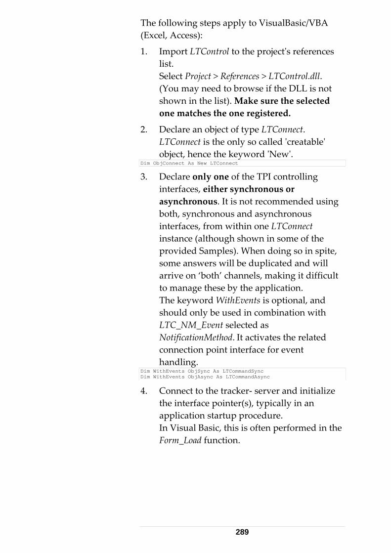
The following steps apply to VisualBasic/VBA (Excel, Access):
1. Import LTControl to the projectʹs references list. Select Project > References > LTControl.dll. (You may need to browse if the DLL is not shown in the list). Make sure the selected one matches the one registered.
2. Declare an object of type LTConnect. LTConnect is the only so called ʹcreatableʹ object, hence the keyword ʹNewʹ.
Dim ObjConnect As New LTConnect
3. Declare only one of the TPI controlling interfaces, either synchronous or asynchronous. It is not recommended using both, synchronous and asynchronous interfaces, from within one LTConnect instance (although shown in some of the provided Samples). When doing so in spite, some answers will be duplicated and will arrive on ‘both’ channels, making it difficult to manage these by the application. The keyword WithEvents is optional, and should only be used in combination with LTC_NM_Event selected as NotificationMethod. It activates the related connection point interface for event handling.
Dim WithEvents ObjSync As LTCommandSync Dim WithEvents ObjAsync As LTCommandAsync
4. Connect to the tracker‐ server and initialize the interface pointer(s), typically in an application startup procedure. In Visual Basic, this is often performed in the Form_Load function.
289
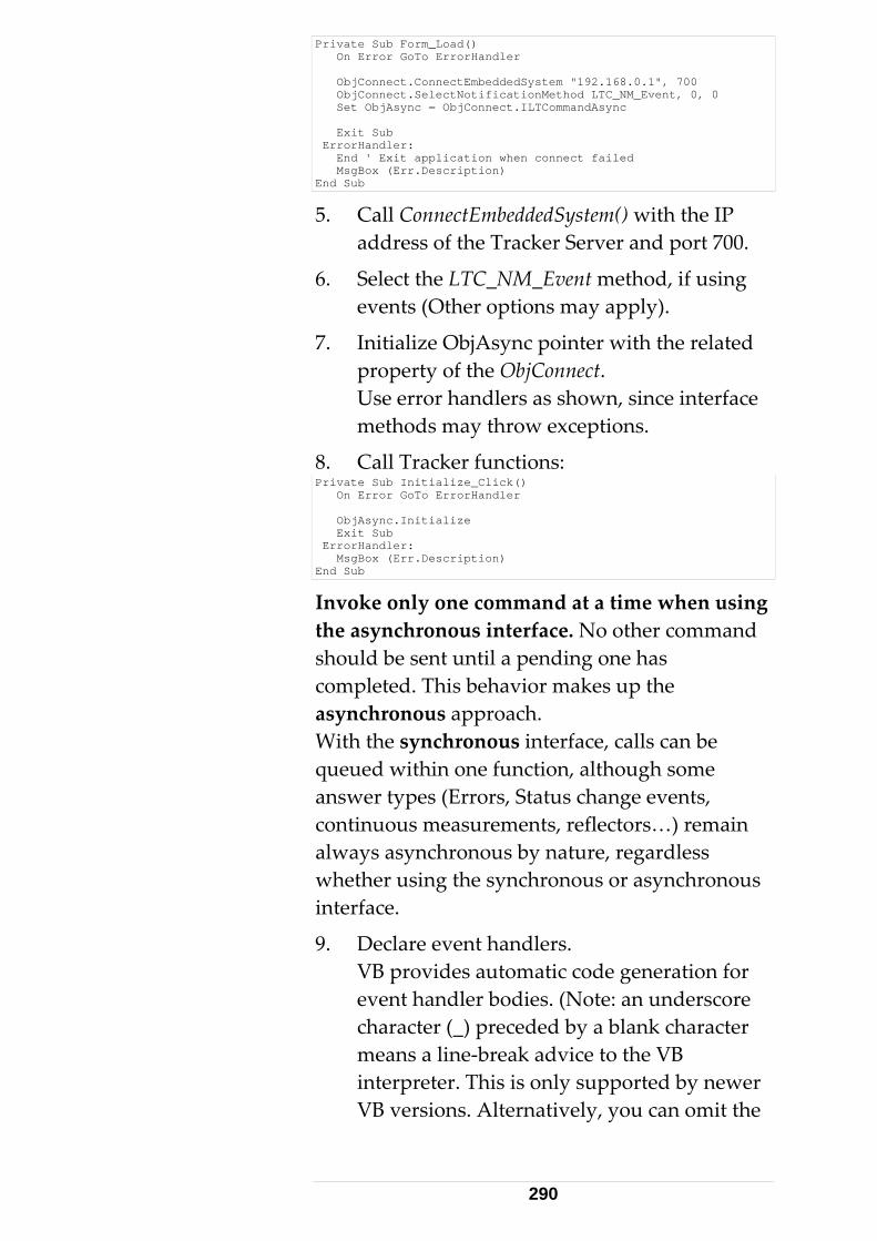
Private Sub Form_Load() On Error GoTo ErrorHandler ObjConnect.ConnectEmbeddedSystem "192.168.0.1", 700 ObjConnect.SelectNotificationMethod LTC_NM_Event, 0, 0 Set ObjAsync = ObjConnect.ILTCommandAsync Exit Sub ErrorHandler: End ' Exit application when connect failed MsgBox (Err.Description) End Sub
5. Call ConnectEmbeddedSystem() with the IP address of the Tracker Server and port 700.
6. Select the LTC_NM_Event method, if using events (Other options may apply).
7. Initialize ObjAsync pointer with the related property of the ObjConnect. Use error handlers as shown, since interface methods may throw exceptions.
8. Call Tracker functions: Private Sub Initialize_Click() On Error GoTo ErrorHandler ObjAsync.Initialize Exit Sub ErrorHandler: MsgBox (Err.Description) End Sub
Invoke only one command at a time when using the asynchronous interface. No other command should be sent until a pending one has completed. This behavior makes up the asynchronous approach. With the synchronous interface, calls can be queued within one function, although some answer types (Errors, Status change events, continuous measurements, reflectors…) remain always asynchronous by nature, regardless whether using the synchronous or asynchronous interface.
9. Declare event handlers. VB provides automatic code generation for event handler bodies. (Note: an underscore character (_) preceded by a blank character means a line‐break advice to the VB interpreter. This is only supported by newer VB versions. Alternatively, you can omit the
290
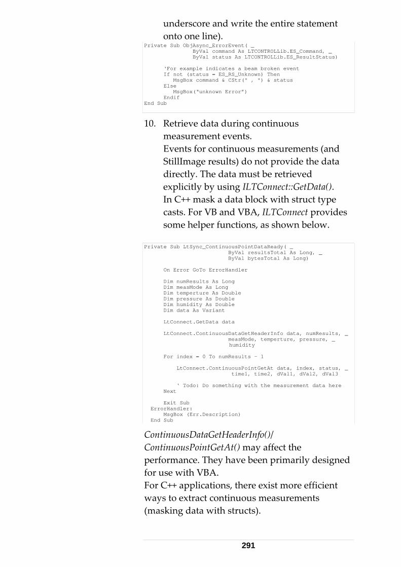
underscore and write the entire statement onto one line).
Private Sub ObjAsync_ErrorEvent( _ ByVal command As LTCONTROLLib.ES_Command, _ ByVal status As LTCONTROLLib.ES_ResultStatus) ‘For example indicates a beam broken event If not (status = ES_RS_Unknown) Then MsgBox command & CStr(" , ") & status Else MsgBox(“unknown Error”) Endif End Sub
10. Retrieve data during continuous measurement events. Events for continuous measurements (and StillImage results) do not provide the data directly. The data must be retrieved explicitly by using ILTConnect::GetData(). In C++ mask a data block with struct type casts. For VB and VBA, ILTConnect provides some helper functions, as shown below.
Private Sub LtSync_ContinuousPointDataReady( _ ByVal resultsTotal As Long, _ ByVal bytesTotal As Long) On Error GoTo ErrorHandler Dim numResults As Long Dim measMode As Long Dim temperture As Double Dim pressure As Double Dim humidity As Double Dim data As Variant LtConnect.GetData data LtConnect.ContinuousDataGetHeaderInfo data, numResults, _ measMode, temperture, pressure, _ humidity For index = 0 To numResults - 1 LtConnect.ContinuousPointGetAt data, index, status, _ time1, time2, dVal1, dVal2, dVal3 ‘ Todo: Do something with the measurement data here Next Exit Sub ErrorHandler: MsgBox (Err.Description) End Sub
ContinuousDataGetHeaderInfo()/ ContinuousPointGetAt() may affect the performance. They have been primarily designed for use with VBA. For C++ applications, there exist more efficient ways to extract continuous measurements (masking data with structs).
291
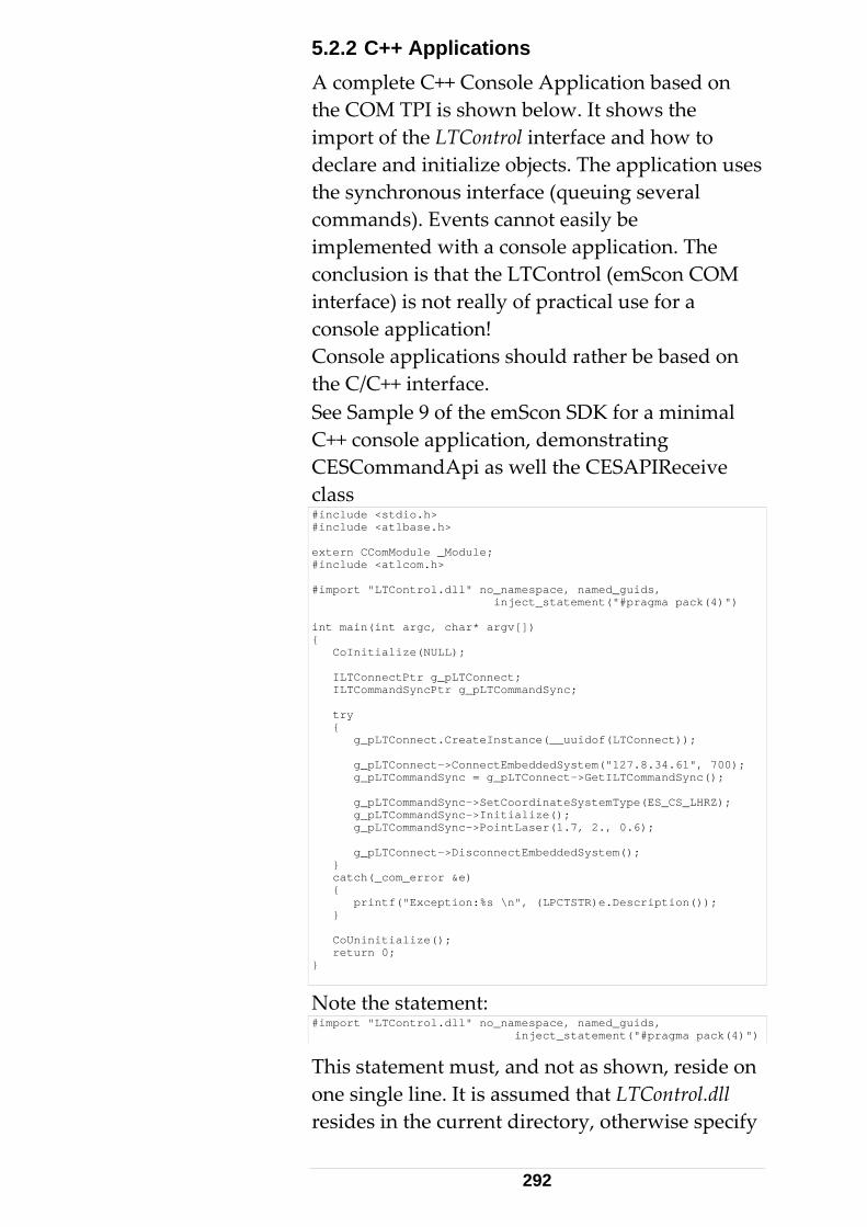
5.2.2 C++ Applications A complete C++ Console Application based on the COM TPI is shown below. It shows the import of the LTControl interface and how to declare and initialize objects. The application uses the synchronous interface (queuing several commands). Events cannot easily be implemented with a console application. The conclusion is that the LTControl (emScon COM interface) is not really of practical use for a console application! Console applications should rather be based on the C/C++ interface. See Sample 9 of the emScon SDK for a minimal C++ console application, demonstrating CESCommandApi as well the CESAPIReceive class #include <stdio.h> #include <atlbase.h> extern CComModule _Module; #include <atlcom.h> #import "LTControl.dll" no_namespace, named_guids, inject_statement("#pragma pack(4)") int main(int argc, char* argv[]) { CoInitialize(NULL); ILTConnectPtr g_pLTConnect; ILTCommandSyncPtr g_pLTCommandSync; try { g_pLTConnect.CreateInstance(__uuidof(LTConnect)); g_pLTConnect->ConnectEmbeddedSystem("127.8.34.61", 700); g_pLTCommandSync = g_pLTConnect->GetILTCommandSync(); g_pLTCommandSync->SetCoordinateSystemType(ES_CS_LHRZ); g_pLTCommandSync->Initialize(); g_pLTCommandSync->PointLaser(1.7, 2., 0.6); g_pLTConnect->DisconnectEmbeddedSystem(); } catch(_com_error &e) { printf("Exception:%s \n", (LPCTSTR)e.Description()); } CoUninitialize(); return 0; }
Note the statement: #import "LTControl.dll" no_namespace, named_guids, inject_statement("#pragma pack(4)")
This statement must, and not as shown, reside on one single line. It is assumed that LTControl.dll resides in the current directory, otherwise specify
292
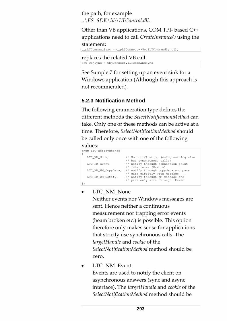
the path, for example ..\ES_SDK\lib\LTControl.dll.
Other than VB applications, COM TPI‐ based C++ applications need to call CreateInstance() using the statement: g_pLTCommandSync = g_pLTConnect->GetILTCommandSync();
replaces the related VB call: Set ObjSync = ObjConnect.ILTCommandSync
See Sample 7 for setting up an event sink for a Windows application (Although this approach is not recommended). 5.2.3 Notification Method The following enumeration type defines the different methods the SelectNotificationMethod can take. Only one of these methods can be active at a time. Therefore, SelectNotificationMethod should be called only once with one of the following values: enum LTC_NotifyMethod { LTC_NM_None, // No notification (using nothing else // but synchronous calls) LTC_NM_Event, // notify through connection point // interfaces (Events) LTC_NM_WM_CopyData, // notify through copydata and pass // data directly with message LTC_NM_WM_Notify, // notify through WM message and // pass only size through lParam };
• LTC_NM_None Neither events nor Windows messages are sent. Hence neither a continuous measurement nor trapping error events (beam broken etc.) is possible. This option therefore only makes sense for applications that strictly use synchronous calls. The targetHandle and cookie of the SelectNotificationMethod method should be zero.
• LTC_NM_Event: Events are used to notify the client on asynchronous answers (sync and async interface). The targetHandle and cookie of the SelectNotificationMethod method should be
293
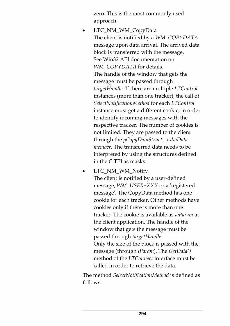
zero. This is the most commonly used approach.
• LTC_NM_WM_CopyData The client is notified by a WM_COPYDATA message upon data arrival. The arrived data block is transferred with the message. See Win32 API documentation on WM_COPYDATA for details. The handle of the window that gets the message must be passed through targetHandle. If there are multiple LTControl instances (more than one tracker), the call of SelectNotificationMethod for each LTControl instance must get a different cookie, in order to identify incoming messages with the respective tracker. The number of cookies is not limited. They are passed to the client through the pCopyDataStruct → dwData member. The transferred data needs to be interpreted by using the structures defined in the C TPI as masks.
• LTC_NM_WM_Notify The client is notified by a user‐defined message, WM_USER+XXX or a ʹregistered messageʹ. The CopyData method has one cookie for each tracker. Other methods have cookies only if there is more than one tracker. The cookie is available as wParam at the client application. The handle of the window that gets the message must be passed through targetHandle. Only the size of the block is passed with the message (through lParam). The GetData() method of the LTConnect interface must be called in order to retrieve the data.
The method SelectNotificationMethod is defined as follows:
294
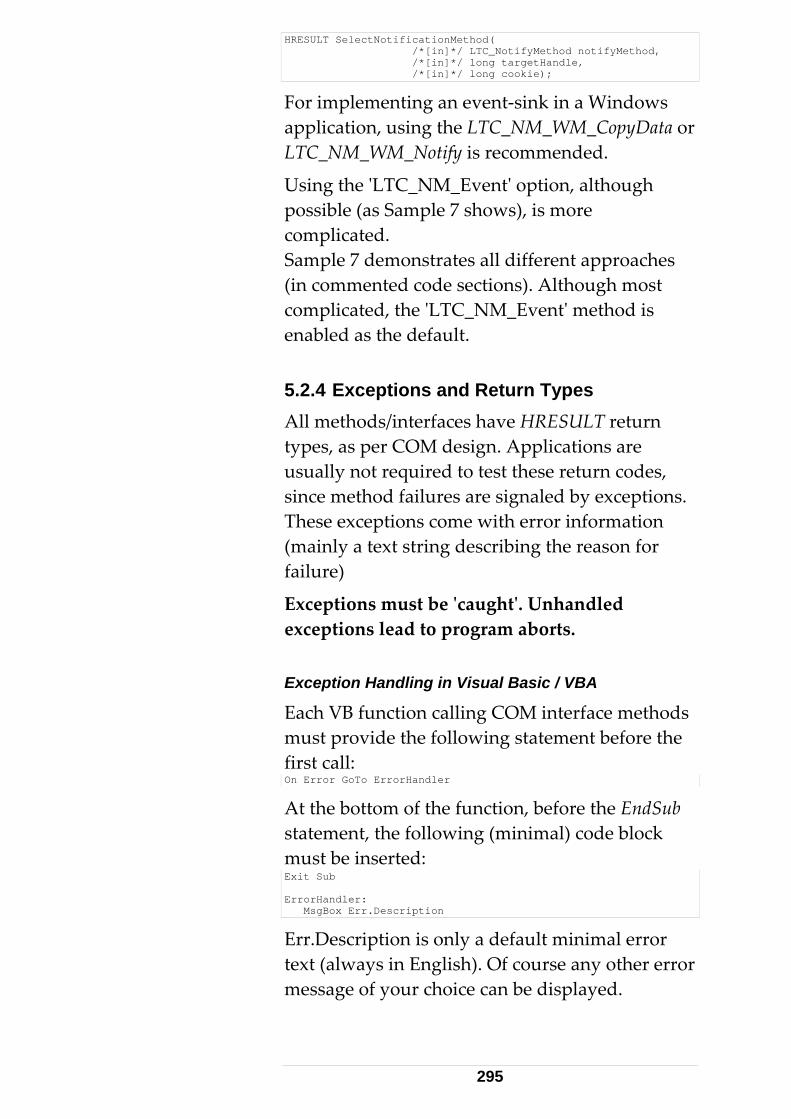
HRESULT SelectNotificationMethod( /*[in]*/ LTC_NotifyMethod notifyMethod, /*[in]*/ long targetHandle, /*[in]*/ long cookie);
For implementing an event‐sink in a Windows application, using the LTC_NM_WM_CopyData or LTC_NM_WM_Notify is recommended.
Using the ʹLTC_NM_Eventʹ option, although possible (as Sample 7 shows), is more complicated. Sample 7 demonstrates all different approaches (in commented code sections). Although most complicated, the ʹLTC_NM_Eventʹ method is enabled as the default. 5.2.4 Exceptions and Return Types All methods/interfaces have HRESULT return types, as per COM design. Applications are usually not required to test these return codes, since method failures are signaled by exceptions. These exceptions come with error information (mainly a text string describing the reason for failure)
Exceptions must be ʹcaughtʹ. Unhandled exceptions lead to program aborts. Exception Handling in Visual Basic / VBA
Each VB function calling COM interface methods must provide the following statement before the first call: On Error GoTo ErrorHandler
At the bottom of the function, before the EndSub statement, the following (minimal) code block must be inserted: Exit Sub ErrorHandler: MsgBox Err.Description
Err.Description is only a default minimal error text (always in English). Of course any other error message of your choice can be displayed.
295
To get the related error number rather than the default‐ text, the error handler may look as follows: Exit Sub ErrorHandler: MsgBox (CStr("Error occurred: ") & _ ObjConnect.LastResultStatus)
Use the LastResultStatus property! The term Err.Number relates to a COM error number, which is usually not of interest for the application.
Alternatively, the number of the last error (LastResultStatus property) can also be retrieved with the TPI command ʹGetSystemStatusʹ.
Additional or different error handling code can be inserted after the ErrorHandler label. Exception Handling in C++
In C++ applications, exception handling is performed through try/catch statements. The caught exception is of type _com_error. See Win32API COM documentation for details of ISupportError Interface. try { pLTCommandSync->FindReflector(5.0); } catch(_com_error &e) { MessageBox("Exception:%s", (LPCTSTR)e.Description()); }
e.Description() returns the appropriate default string (same as Err.Description in VB). Try/catch‐ statements may be nested, and are required when queuing several synchronous commands within one C++ function.
If the error number rather than the (default) text is of interest, use the property objConnect.LastResultStatus.
296
try { pLTCommandSync->FindReflector(5.0); } catch(_com_error &e) { MessageBox("Error Nr:%d", pLTConnect->LastResultStatus); }
Alternatively, the number of the last error (LastResultStatus property) can also be retrieved with the TPI command ʹGetSystemStatusʹ. Exception Handling in C#
When using LTControl (COM TPI) with C#, essentially the same concepts as with C++ applies. C# uses a very similar try/catch approach. Evaluating the Return status
The necessary exception handling precludes evaluation of the return status of the COM method call.
Certain constellations, such as S_FALSE return values, may require a distinguished evaluation.
Success return values: S_OK S_FALSE
S_OK is returned for an ordinary success case.
Certain commands may return a TPI result‐status of type Out of Range OK. Example: ES_RS_Parameter1OutOfRangeOK. In this situation, the COM method returns S_FALSE. This means that the command (setting) has succeeded, but that its value is out of specified tolerance. In other words, this means just a warning and thus, no exception will be thrown. appropriate status information can be obtained in two different ways:
• Evaluate the property ILTConnect::LastResultStatus.
• Get the error Information (error string) with GetErrorInfo().
297
Note that there exist only a few commands that may return S_FALSE (For example environment parameter setting commands). BSTR bstrError; IErrorInfo *pInfo; HRESULT hr = GetErrorInfo(0, &pInfo); if(pInfo && SUCCEEDED(pInfo->GetDescription(&bstrError))) { _bstr_t errorString(bstrError); pInfo->Release(); } // if
Failure return value: E_FAIL
In case of any command failure, E_FAIL is returned. This automatically leads to an exception (thrown by the COM framework). 5.2.5 COM TPI supporting Programming Languages • Visual C++
‐ All Interfaces supported.
‐ User defined TypeLibrary (enum, structs) supported.
‐ Event and message notification methods supported.
• VisualBasic (VB 6)
‐ All interfaces supported.
‐ User defined TypeLibrary (enum, structs) supported.
‐ Event and WM Message Notification methods supported (Events to be preferred).
• VisualBasic for Applications (VBA) (Excel, Word, and Access)
‐ All interfaces supported.
‐ User defined types of TypeLibrary (enum, structs) supported with Office 2000, but not fully supported with Office 97.
298
‐ Event notification methods supported (WM Messages not supported).
• C# and VB .NET
‐ All interfaces supported.
‐ User defined types of TypeLibrary (enum, structs) supported
‐ Event notification methods supported
• Scripting Languages (VBS, JavaScript)
Currently not supported. Support of these languages requires ʹDualʹ or IDispatch COM interfaces.
Could be achieved by providing a COM IDispatch wrapper around the LTControls custom interfaces.
• Delphi
‐ All interfaces supported.
‐ User defined types of TypeLibrary (enum, structs) supported
‐ Event notification methods supported
It is recommended to use at least Office 2000 or XP for TPI VBA Programming. Office 97 (Excel 97, Word 97) lacks user‐defined types (UDT) and contains some bugs that make development of TPI clients virtually impossible, as soon as events are involved.
Interface methods using ʹstructʹ parameters, which do not support UDT (Office 97 only), cannot be used from within VBA. However, functions are available based on basic data types, as a work around.
Older versions of VBA may lack support of enum‐type symbols, so they need to be passed as 4 Byte (long) values. Therefore the numerical representation of particular enum values must be
299
known. In C‐language TPI, these values are explicitly enumerated.
See ES_C_API_Def.h in SDK, for enum definitions. A type library viewer will also show the numerical values.
Example Enum definition: enum ES_TrackerTemperatureRange { ES_TR_Low, ES_TR_Medium, ES_TR_High, ES_TR_Automatic, };
ES_ TR_Low =0, TR_Medium=1, ES_TR_High=2 and ES_TR_Automatic=3.
• Command in a VB application ObjSync.SetTemperatureRange ES_TR_High
• Command in (old version) VBA ObjSync.SetTemperatureRange 2
Only use the second approach if the first one is not supported with your programming environment! 5.2.6 Proper Interface Selection Unlike the C and C++ TPI, the COM TPI is a DLL library and not an include file. This DLL provides an easy to use programming interface for the Tracker Server. This makes it suitable for programmers with minimal programming expertise to design simple tracker applications. The COM TPI also opens doors to programming languages such as VisualBasic, Delphi, C#, VB.NET, VBA (Office Macro Languages) etc.
The interface is made‐ up of a so‐called COM component. It is designed as an ATL DLL COM server. The DLL is named ʹLTControl.dllʹ and comes as part of the emScon SDK. LTControl provides built‐in TCP/IP communication.
The LTControl COM‐object DLL is based on the tracker server C++ TPI, the Win32 Sockets 2.0 API
300
and VC++ ATL. The LTControl.dll is, in a sense, a Tracker Server C++ Client. However it acts as Server from applications (based on LTControl) point of view.
The programmer is not required to deal with TCP/IP communication libraries or system programming interfaces.
The high‐level TPI supports both synchronous and asynchronous methods. Note: Using the ‘synchronous’ interface may provide some convenient properties. However, there are also some disadvantages: Long‐ taking actions cannot be interrupted (FindReflector, OrientToGravity..), as this is possible with asynchronous communication on using ‘StopMeasurement’ command. Synchronous commands also imply potential timeouts. The COM component is binary and thus also lacks transparency. Other than with the C/C++ interface, no debugging down to the source level is possible. For highly professional applications, we rather recommend programming in C++ or C#, hence using the C++ or C# interface directly (which are asynchronous be design).
COM objects expose ʹinterfacesʹ, described by a Type‐Library, which is implicitly included in the DLL. A pure Type Library LTControl.tlb is also available, although not really needed. This High‐level interface does not provide any additional functions (in terms of Tracker Server controlling functions). LTControl is strictly based on the C++‐TPI, with a high‐level, convenient programming interface.
COM interfaces work well together with Visual Basic, Delphi and Office Macro programming languages (VBA) on the Win32 platform, while using the emScon C or C++ interface is difficult for those types of languages.
301
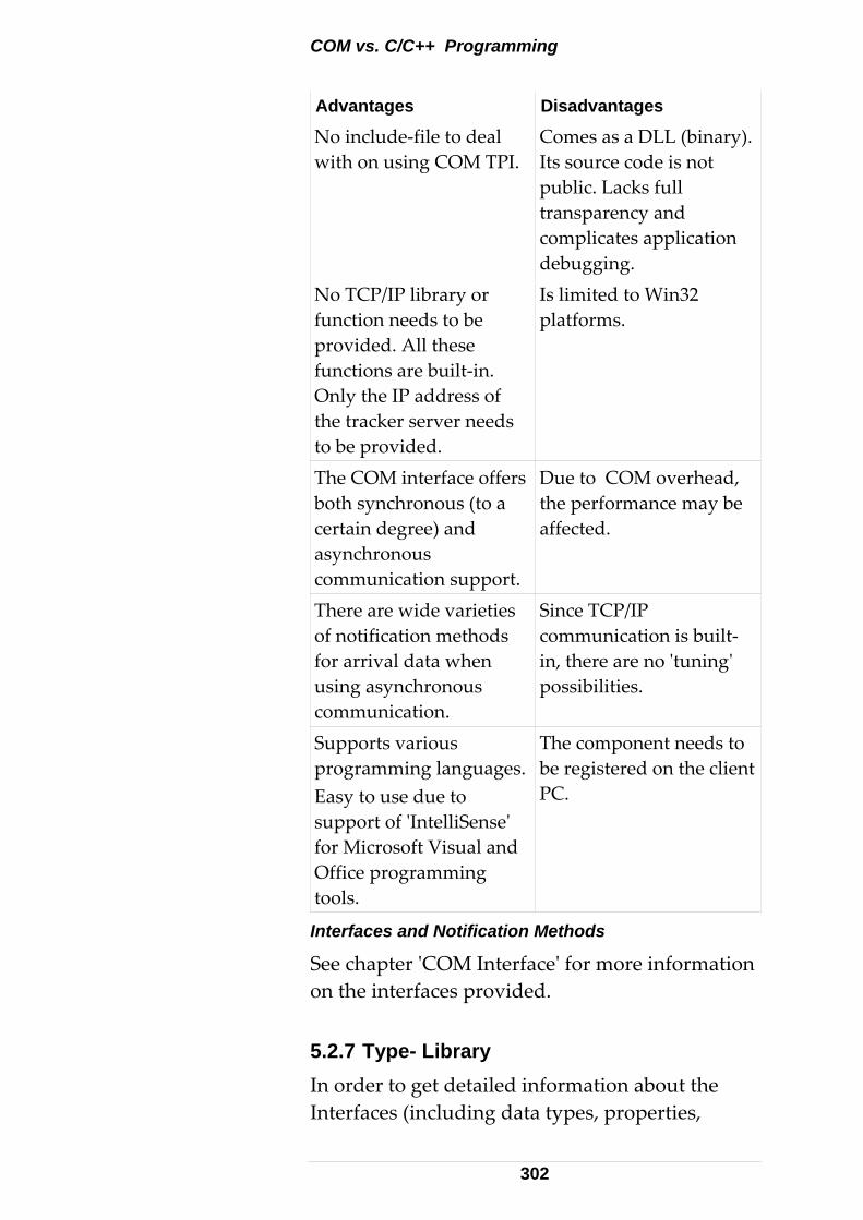
COM vs. C/C++ Programming
Advantages Disadvantages
No include‐file to deal with on using COM TPI.
Comes as a DLL (binary). Its source code is not public. Lacks full transparency and complicates application debugging.
No TCP/IP library or function needs to be provided. All these functions are built‐in. Only the IP address of the tracker server needs to be provided.
Is limited to Win32 platforms.
Due to COM overhead, the performance may be affected.
The COM interface offers both synchronous (to a certain degree) and asynchronous communication support.
Since TCP/IP communication is built‐in, there are no ʹtuningʹ possibilities.
There are wide varieties of notification methods for arrival data when using asynchronous communication.
The component needs to be registered on the client PC.
Supports various programming languages.Easy to use due to support of ʹIntelliSenseʹ for Microsoft Visual and Office programming tools.
Interfaces and Notification Methods
See chapter ʹCOM Interfaceʹ for more information on the interfaces provided. 5.2.7 Type- Library In order to get detailed information about the Interfaces (including data types, properties,
302
methods and events) exposed by a COM object, a COM viewer may be used. Visual Studio offers such a viewer: The OLE/COM Object Viewer can be launched from the Tools menu of VC++.
File > View Type Lib > LTControl.dll or LTControl.tlb. 5.2.8 COM TPI Reference The type library of a COM object can be seen as Interface Reference.
Listing all the methods redundantly in this manual would not make sense.
The type library enables a development environment to provide ʹIntelliSenseʹ support. That is, the development environment supports the programmer in selecting methods and parameters in an active manner.
The method names of the COM TPI partly differ from those of the C++ interface (Although most of them – especially the ʹSet/Getʹ functions – are named accordingly). This ʹinconsistencyʹ comes from the high‐ level approach of certain methods. However, by viewing the list of available functions (type‐ library, Intellisense), it is quite easy to find the proper methods and their relatives to the C / C++ interface (where the parameters are described).
Note that asynchronous methods never return any data. Data is returned through events in these cases. On the other hand, synchronous methods always return the result data (if any) as parameters.
Concerning input parameters (sent to the tracker server), there is no difference between the synchronous and asynchronous approach. Note: The event [id(76), ʺSystemParameterDataʺ] of the interface _ILTCommandAsyncEvents should no longer be used. For new applications,
303
use [id(80), ʺLongSystemParameterDataʺ] instead. The former one is only kept to ensure compatibility to existing applications. Old and new event only differ by name (and dispatch ID). The parameter list remains unchanged. The reason for the name change is to avoid a mess‐up with the newly introduced event ʺDoubleSystemParameterDataʺ. 5.2.9 Registering COM Objects COM objects must be registered on the application PC before they can be used. For details refer to the ʹReadme.txtʹ file that comes with the SDK (Lib folder) 5.2.10 Synchronous versus Asynchronous Interface When designing a client application using the LTControl COM component, either the synchronous or asynchronous interface can be used.
Differences between the synchronous and asynchronous interface.
• The functions of the synchronous interface do not return before the task is completed, while the asynchronous functions do so (see C/C++‐TPI).
• In general, programming with synchronous functions is much easier. Handling Data‐Arrival Events or Notifications is not required (except in some special cases).
• With the asynchronous interface and the events notification (that is, calling SelectNotificationMethod with LTC_NM_Event), an Event‐ Sink must be implemented. In VB, this is done by defining the WithEvents keyword, but in C++ this is a bit more complicated. In addition, the appropriate event handlers must be
304
implemented. With any other notification mechanism, the event sink is not required and the WithEvents keyword must be removed. Implement Windows Message handlers, not Event handlers, in this case.
• With the synchronous interface, some answers remain asynchronous by their nature ‐ continuous measurement packets, Reflectors and error answers (these may partly occur non‐command related, for example beam broken). With synchronous commands, events or notifications must still be caught ‐ See former paragraph. Any other notification mechanism does not need an event sink, and the WithEvents keyword must be removed. In this case, do not implement Event handlers; appropriate Windows Message handlers must be implemented instead.
• Using both interfaces in the same LTConnect instance – although possible – usually makes no sense and partly leads to duplicate answers. Use of both interfaces within one and the same application is therefore not recommended. 5.2.11 Visual Basic Boolean variable evaluation
• Do not test explicitly against the VB keyword ʹTrueʹ when using Get<FunctionName>Ex methods of the LTControl, for those commands returning Boolean data within their result structure. This is because the Boolean member in these structures, if true, is one (1). However, the VB keyword ʹTrueʹ evaluates to (‐1). Always test the variable as a logical expression, or against ʹNot Falseʹ.
305
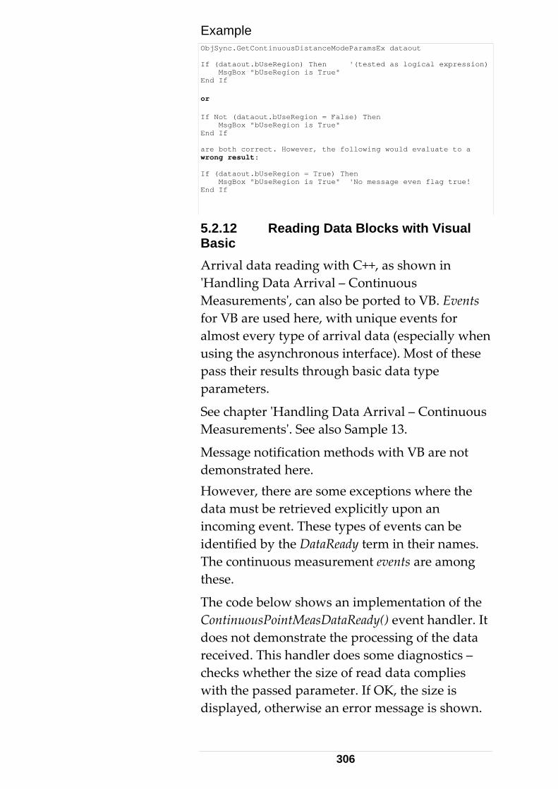
Example ObjSync.GetContinuousDistanceModeParamsEx dataout If (dataout.bUseRegion) Then '(tested as logical expression) MsgBox "bUseRegion is True" End If or If Not (dataout.bUseRegion = False) Then MsgBox "bUseRegion is True" End If are both correct. However, the following would evaluate to a wrong result: If (dataout.bUseRegion = True) Then MsgBox "bUseRegion is True" 'No message even flag true! End If
5.2.12 Reading Data Blocks with Visual Basic Arrival data reading with C++, as shown in ʹHandling Data Arrival – Continuous Measurementsʹ, can also be ported to VB. Events for VB are used here, with unique events for almost every type of arrival data (especially when using the asynchronous interface). Most of these pass their results through basic data type parameters.
See chapter ʹHandling Data Arrival – Continuous Measurementsʹ. See also Sample 13.
Message notification methods with VB are not demonstrated here. However, there are some exceptions where the data must be retrieved explicitly upon an incoming event. These types of events can be identified by the DataReady term in their names. The continuous measurement events are among these.
The code below shows an implementation of the ContinuousPointMeasDataReady() event handler. It does not demonstrate the processing of the data received. This handler does some diagnostics – checks whether the size of read data complies with the passed parameter. If OK, the size is displayed, otherwise an error message is shown.
306
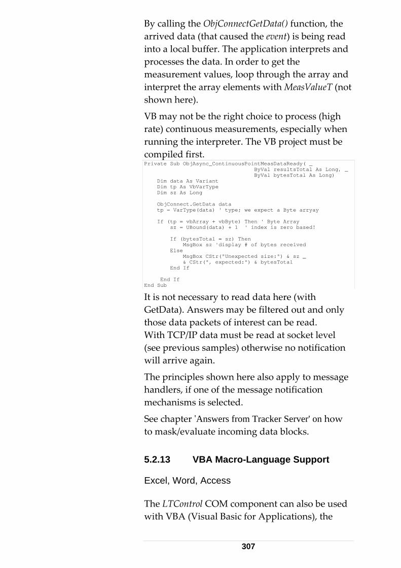
By calling the ObjConnectGetData() function, the arrived data (that caused the event) is being read into a local buffer. The application interprets and processes the data. In order to get the measurement values, loop through the array and interpret the array elements with MeasValueT (not shown here).
VB may not be the right choice to process (high rate) continuous measurements, especially when running the interpreter. The VB project must be compiled first. Private Sub ObjAsync_ContinuousPointMeasDataReady( _ ByVal resultsTotal As Long, _ ByVal bytesTotal As Long) Dim data As Variant Dim tp As VbVarType Dim sz As Long ObjConnect.GetData data tp = VarType(data) ' type; we expect a Byte arryay If (tp = vbArray + vbByte) Then ' Byte Array sz = UBound(data) + 1 ' index is zero based! If (bytesTotal = sz) Then MsgBox sz 'display # of bytes received Else MsgBox CStr("Unexpected size:") & sz _ & CStr(", expected:") & bytesTotal End If End If End Sub
It is not necessary to read data here (with GetData). Answers may be filtered out and only those data packets of interest can be read. With TCP/IP data must be read at socket level (see previous samples) otherwise no notification will arrive again.
The principles shown here also apply to message handlers, if one of the message notification mechanisms is selected.
See chapter ʹAnswers from Tracker Server' on how to mask/evaluate incoming data blocks. 5.2.13 VBA Macro-Language Support Excel, Word, Access The LTControl COM component can also be used with VBA (Visual Basic for Applications), the
307
built‐in Macro language of MS Excel, Word and Access – with the exception that structs and enums are not fully supported with VBA that comes with Office 97. ʹExʹ functions that take struct parameters cannot be used. VBA that comes with Office 2000 no longer has such limitations. It is highly recommended to use Office 2000 or higher for Tracker Server VBA Programming. Office 97 (Excel 97/Word 97) ‐ apart from a missing UDT ‐ contain some bugs that make development of Tracker Server clients virtually impossible, as soon as events are involved. This bug leads to a completely corrupted file upon file saving, after an event has arrived. For this reason, Excel samples delivered with the TPI‐SDK are in Excel 2000 format. They may run with Excel 97 , but may be destroyed as soon as any changes are saved. Always maintain a safe (read‐only) copy. The following remarks only apply to Office 97 programming (Office 2000 VBA behaves as ordinary VB).
User-defined Types, the Differences between Visual Basic and VBA97
• Both allow defining user‐defined structs locally. However, those structs exported by the LTControl (such as PacketHeaderT, SingleMeasResultT) are only recognized from within Visual Basic. VBA claims an error Automation type not supported if declaring, for example, a variable like:
Dim val As SingleMeasResultT // works with VB, but not VBA97
• Enums are not supported by VBA97. The compiler does not know the keyword Enum. User‐defined enums cannot be defined locally, although this works with ordinary Visual Basic. It is also not possible to use enum‐ type variables that are exported by the
308
LTControl. Declaration as follows are not possible in VBA97:
Dim cmd as ES_Command // works with VB, but not VBA97
• When implementing an EventHandler that has enum‐type parameters in Visual Basic will read as follows (only function header shown):
Private Sub CommandSync_ErrorEvent( _ ByVal command As LTCONTROLLib.ES_Command, _ ByVal status As LTCONTROLLib.ES_ResultStatus)
• When doing the same in VBA97 it will read as follows:
Private Sub CommandSync_ErrorEvent(ByVal command As Long, _ ByVal status As Long)
Visual Basic keeps the enum type information and recognizes the parameters with their correct enum‐ types, while VBA just passes them as long parameters. However, the symbols of the enum values are correctly recognized, although not checked by the compiler for correct typing (which can lead to errors, which are difficult to find). This problem is not specific to VBA, it also exists in VB. There are two different situations where enums and their value‐ symbols affect the interface:
Method takes enum type parameters, for example, call SetMeasurementMode the same way for both VB and VBA:
ObjSync.SetMeasurementMode ES_MM_ContinuousDistance
1. ES_MM_ContinuousDistance will be correctly recognized as having the value ʹ2ʹ (see enum definition).
2. Correct typing of values: VB as well as the VBA interpreter will not recognize typing errors in enum symbols here. However, both VB and VBA provide ʹIntelliSenseʹ, providing for a selection from a list rather than having to type them in.
3. Event handlers, as we have seen above, pass enums as long values in VBA. The
309
incoming values can be tested against enum symbols. In an event handler, the following code might be typical (example ErrorEvent in VBA):
Private Sub CommandSync_ErrorEvent(ByVal command As Long, _ ByVal status As Long) If (command = ES_C_Initialize) Then ' do something End If If (status = ES_RS_NoTPFound) Then ' do something End If End Sub
Use extreme caution while typing the symbols with VBA 97. No ʹIntelliSenseʹ support is available.
Summary
• There is no problem with enums and VBA97. It is just a potential error source due to missing type checking.
• Structs (unless locally defined) are not supported in VBA97. LTControl always offers an alternative to those functions returning struct parameters.
• None of the event functions has struct parameters (technical restriction), and have, therefore, no restriction with VBA97. 5.2.14 Continuous measurements and VBA Events of continuous measurements do not directly pass the data.
See chapter ʹHandling Data Arrival – Continuous Measurements ʹ for details.
Handling continuous measurements within VBA requires care. Events can be ʹsubscribedʹ with the WithEvent keyword and pending data can be read with GetData(), as shown in:
See chapter ʹReading Data Blocks with Visual Basicʹ for details. Also see Sample 13 for a working code example.
310
Masking Data
The unavailability of (LTControl) structures in VBA prevents masking the data. With the byte‐layout of the data blocks, the appropriate bytes can be extracted ʹmanuallyʹ and assigned to basic data types. This is not convenient and exceeds the typical Excel programmerʹs expertise.
Even with VB, although structs are available, masking data is not as easy as in C++. By providing some helper functions, data blocks can be copied to appropriate struct parameters instead of using pointer type‐casts: ILTConnect::ContinuousDataGetHeaderInfo() ILTConnect::ContinuousPointGetAt() ILTConnect::ContinuousPoint2GetAt() ILTConnect::Continuous6DDataGetAt()
This allows extracting information of interest from data blocks of type ES_DT_MultiMeasResult, ES_DT_MultiMeasResult2 and ES_DT_Multi6DMeasResult.
A VB (VBA) implementation of the ContinuousPointMeasDataReady event handler that demonstrates usage of these functions reads as follows (note the many comments):
311
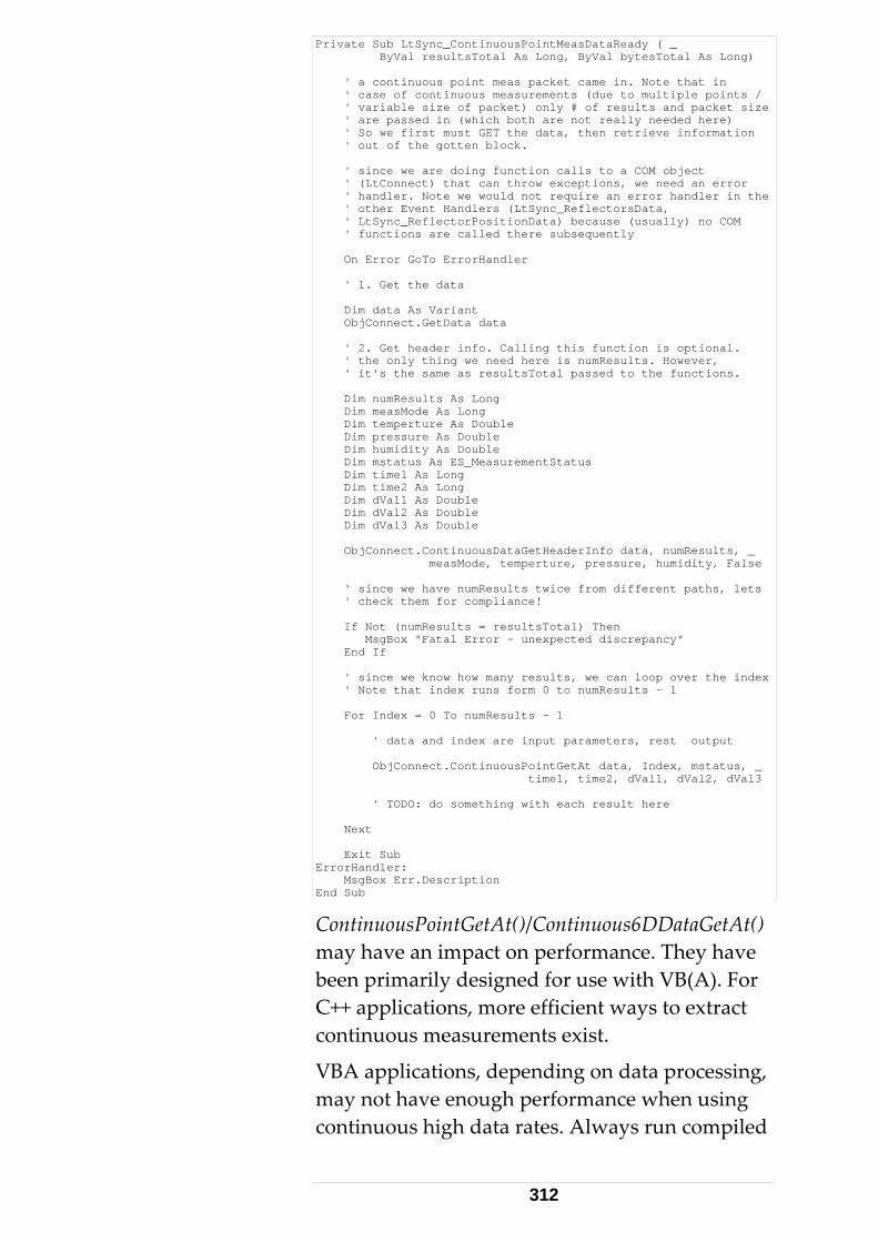
Private Sub LtSync_ContinuousPointMeasDataReady ( _ ByVal resultsTotal As Long, ByVal bytesTotal As Long) ' a continuous point meas packet came in. Note that in ' case of continuous measurements (due to multiple points / ' variable size of packet) only # of results and packet size ' are passed in (which both are not really needed here) ' So we first must GET the data, then retrieve information ' out of the gotten block. ' since we are doing function calls to a COM object ' (LtConnect) that can throw exceptions, we need an error ' handler. Note we would not require an error handler in the ' other Event Handlers (LtSync_ReflectorsData, ' LtSync_ReflectorPositionData) because (usually) no COM ' functions are called there subsequently On Error GoTo ErrorHandler ' 1. Get the data Dim data As Variant ObjConnect.GetData data ' 2. Get header info. Calling this function is optional. ' the only thing we need here is numResults. However, ' it's the same as resultsTotal passed to the functions. Dim numResults As Long Dim measMode As Long Dim temperture As Double Dim pressure As Double Dim humidity As Double Dim mstatus As ES_MeasurementStatus Dim time1 As Long Dim time2 As Long Dim dVal1 As Double Dim dVal2 As Double Dim dVal3 As Double ObjConnect.ContinuousDataGetHeaderInfo data, numResults, _ measMode, temperture, pressure, humidity, False ' since we have numResults twice from different paths, lets ' check them for compliance! If Not (numResults = resultsTotal) Then MsgBox "Fatal Error - unexpected discrepancy" End If ' since we know how many results, we can loop over the index ' Note that index runs form 0 to numResults - 1 For Index = 0 To numResults - 1 ' data and index are input parameters, rest output ObjConnect.ContinuousPointGetAt data, Index, mstatus, _ time1, time2, dVal1, dVal2, dVal3 ' TODO: do something with each result here Next Exit Sub ErrorHandler: MsgBox Err.Description End Sub
ContinuousPointGetAt()/Continuous6DDataGetAt() may have an impact on performance. They have been primarily designed for use with VB(A). For C++ applications, more efficient ways to extract continuous measurements exist.
VBA applications, depending on data processing, may not have enough performance when using continuous high data rates. Always run compiled
312
versions. In special cases the incoming results need to be buffered.
Use of values instead of symbols, in Visual Basic, avoids the problem of typing incorrect enum symbols, which cause errors difficult to detect.
A complete .tlh file is automatically generated when importing LTControl.tlb into a VC++ project. 5.2.15 Scripting Language Support Pure scripting languages VBS (Visual Basic Script), JavaScript etc. are currently not supported by the LTControl COM component.
This would require IDispatch interfaces rather than custom interfaces. Combinations of IDispatch and custom interfaces (dual interfaces) have the same disadvantage as IDispatch – lack of performance. 5.2.16 Exception Handling for Non- Microsoft Clients The emScon LTControl COM interface also supports Windows application development with some Non‐ Microsoft Tools, such as Borland Delphi.
For such applications, it may be necessary to set the property ʹLTConnect::ExceptionHandlingPolicyʹ to 1 (Before connecting to emScon server). Otherwise exceptions may not be raised in the client application. Do not set this property for Microsoft clients (VB, C++, C#, Excel..), that is, leave its default value 0.
For further information, see commented code in Sample 20 (LtcDelphiClient), where this property is set to 1.
Example (Delphi): LTConnect.Set_ExceptionHandlingPolicy(1);
313
5.2.17 Multi- Tracker Applications For multi tracker applications, create a separate instance of ʹLTConnectʹ for each tracker/ controller. For single‐threaded applications, the usage of the asynchronous interface is compulsory in order to allow ʹparallelʹ control of multiple trackers. If using the synchronous interface, the application will not be able to do parallel calls to multiple trackers! That means the application waits for pending answers from any tracker before another command (to the same or another tracker) can be issued. As an example, consider a 2‐tracker application using the synchronous interface that wants to initialize both trackers upon startup. With a single‐ threaded approach, initialization can only be performed for one tracker after another. Especially for long‐time taking commands like ʹInitializeʹ, it would of course be convenient to execute this command in parallel for both trackers. In order to do so, the application must provide a separate thread for every instance of the LTControl/LTConnect. Note that LTControl is designed to run in so‐called ʹApartment Threadedʹ context. For details about this, refer to Microsoft documentation. For our purpose, there is no need to go too far into details; we just provide some code‐fragments in order to illustrate how multithreaded applications (using the LTControl) have to be set‐ up (for different programming languages). Using COM Control for Multi- Tracker Support in C++ Take Sample 7 (C++ application using the emScon COM‐ interface) as a basis. Consider weʹd like to extend this application in order to control a 2nd tracker in parallel. Any C++ application using COM needs to make a
314
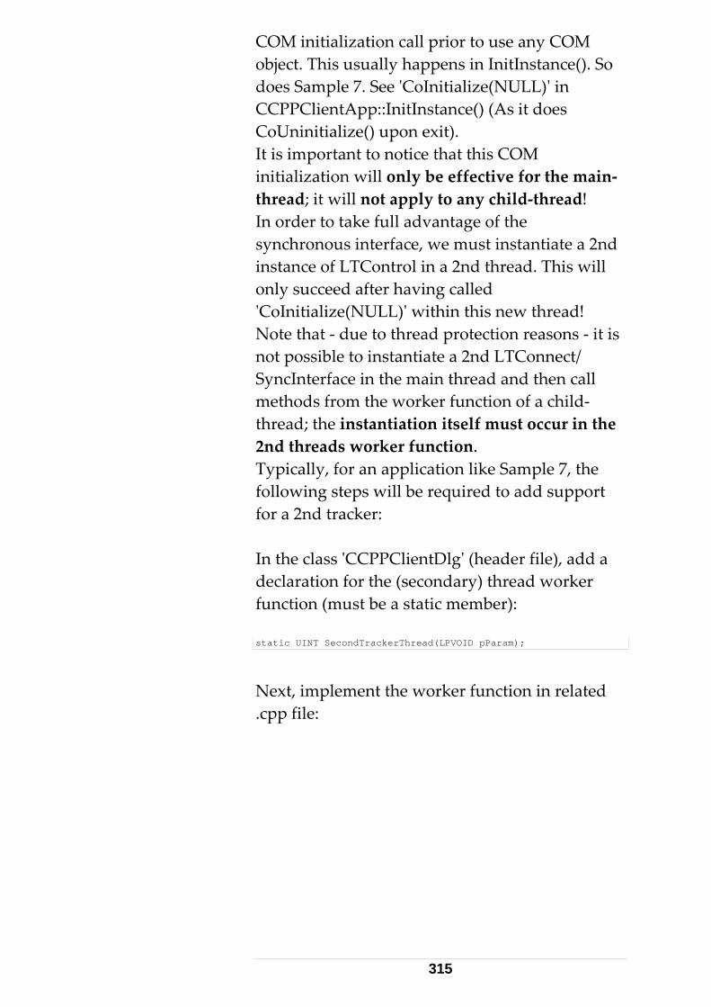
COM initialization call prior to use any COM object. This usually happens in InitInstance(). So does Sample 7. See ʹCoInitialize(NULL)ʹ in CCPPClientApp::InitInstance() (As it does CoUninitialize() upon exit). It is important to notice that this COM initialization will only be effective for the main‐ thread; it will not apply to any child‐thread! In order to take full advantage of the synchronous interface, we must instantiate a 2nd instance of LTControl in a 2nd thread. This will only succeed after having called ʹCoInitialize(NULL)ʹ within this new thread! Note that ‐ due to thread protection reasons ‐ it is not possible to instantiate a 2nd LTConnect/ SyncInterface in the main thread and then call methods from the worker function of a child‐ thread; the instantiation itself must occur in the 2nd threads worker function. Typically, for an application like Sample 7, the following steps will be required to add support for a 2nd tracker: In the class ʹCCPPClientDlgʹ (header file), add a declaration for the (secondary) thread worker function (must be a static member): static UINT SecondTrackerThread(LPVOID pParam);
Next, implement the worker function in related .cpp file:
315
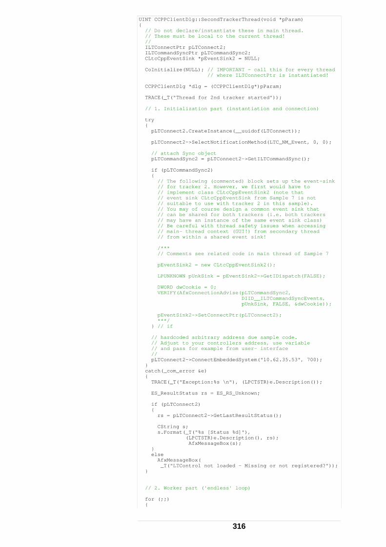
UINT CCPPClientDlg::SecondTrackerThread(void *pParam) { // Do not declare/instantiate these in main thread. // These must be local to the current thread! // ILTConnectPtr pLTConnect2; ILTCommandSyncPtr pLTCommandSync2; CLtcCppEventSink *pEventSink2 = NULL; CoInitialize(NULL); // IMPORTANT - call this for every thread // where ILTConnectPtr is instantiated! CCPPClientDlg *dlg = (CCPPClientDlg*)pParam; TRACE(_T("Thread for 2nd tracker started")); // 1. Initialization part (instantiation and connection) try { pLTConnect2.CreateInstance(__uuidof(LTConnect)); pLTConnect2->SelectNotificationMethod(LTC_NM_Event, 0, 0); // attach Sync object pLTCommandSync2 = pLTConnect2->GetILTCommandSync(); if (pLTCommandSync2) { // The following (commented) block sets up the event-sink // for tracker 2. However, we first would have to // implement class CLtcCppEventSink2 (note that // event sink CLtcCppEventSink from Sample 7 is not // suitable to use with tracker 2 in this sample). // You may of course design a common event sink that // can be shared for both trackers (i.e. both trackers // may have an instance of the same event sink class) // Be careful with thread safety issues when accessing // main- thread context (GUI!) from secondary thread // from within a shared event sink! /*** // Comments see related code in main thread of Sample 7 pEventSink2 = new CLtcCppEventSink2(); LPUNKNOWN pUnkSink = pEventSink2->GetIDispatch(FALSE); DWORD dwCookie = 0; VERIFY(AfxConnectionAdvise(pLTCommandSync2, DIID__ILTCommandSyncEvents, pUnkSink, FALSE, &dwCookie)); pEventSink2->SetConnectPtr(pLTConnect2); ***/ } // if // hardcoded arbitrary address due sample code. // Adjust to your controllers address, use variable // and pass for example from user- interface // pLTConnect2->ConnectEmbeddedSystem("10.62.35.53", 700); } catch(_com_error &e) { TRACE(_T("Exception:%s \n"), (LPCTSTR)e.Description()); ES_ResultStatus rs = ES_RS_Unknown; if (pLTConnect2) { rs = pLTConnect2->GetLastResultStatus(); CString s; s.Format(_T("%s [Status %d]"), (LPCTSTR)e.Description(), rs); AfxMessageBox(s); } else AfxMessageBox( _T("LTControl not loaded - Missing or not registered?")); } // 2. Worker part ('endless' loop) for (;;) {
316
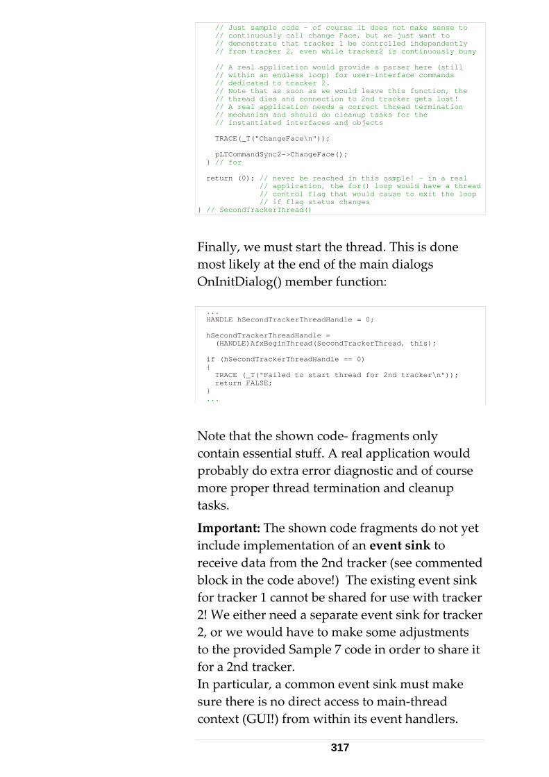
// Just sample code - of course it does not make sense to // continuously call change Face, but we just want to // demonstrate that tracker 1 be controlled independently // from tracker 2, even while tracker2 is continuously busy // A real application would provide a parser here (still // within an endless loop) for user-interface commands // dedicated to tracker 2. // Note that as soon as we would leave this function, the // thread dies and connection to 2nd tracker gets lost! // A real application needs a correct thread termination // mechanism and should do cleanup tasks for the // instantiated interfaces and objects TRACE(_T("ChangeFace\n")); pLTCommandSync2->ChangeFace(); } // for return (0); // never be reached in this sample! - in a real // application, the for() loop would have a thread // control flag that would cause to exit the loop // if flag status changes } // SecondTrackerThread()
Finally, we must start the thread. This is done most likely at the end of the main dialogs OnInitDialog() member function: ... HANDLE hSecondTrackerThreadHandle = 0; hSecondTrackerThreadHandle = (HANDLE)AfxBeginThread(SecondTrackerThread, this); if (hSecondTrackerThreadHandle == 0) { TRACE (_T("Failed to start thread for 2nd tracker\n")); return FALSE; } ...
Note that the shown code‐ fragments only contain essential stuff. A real application would probably do extra error diagnostic and of course more proper thread termination and cleanup tasks.
Important: The shown code fragments do not yet include implementation of an event sink to receive data from the 2nd tracker (see commented block in the code above!) The existing event sink for tracker 1 cannot be shared for use with tracker 2! We either need a separate event sink for tracker 2, or we would have to make some adjustments to the provided Sample 7 code in order to share it for a 2nd tracker. In particular, a common event sink must make sure there is no direct access to main‐thread context (GUI!) from within its event handlers.
317
Otherwise this would lead to access violations if these event handlers were being triggered by the 2nd thread. As far as we just do endless calls of synchronous functions (i.e. ʹChangeFaceʹ in our sample), receiving data trough events may not be an issue for the 2nd thread. (But even when only using synchronous calls, an event sink at least for unsolicited errors and events ‐ such as ʹbeam breakʹ ‐ should be provided anyway! ) The simplest approach was to duplicate the class ʹCLtcCppEventSinkʹ (Sample 7, files LtcCPPEventSink.h /cpp) for a new class ʹCLtcCppEventSink2ʹ (especially if 2nd tracker supports a different set of commands being called and therefore applies to a different set of event handlers). Using the same event sink class for both trackers (i.e. two instances of the one and only class ʹCLtcCppEventSinkʹ) is possible, but again, be careful concerning thread protection and shared data issues etc. There are many potential pitfalls to this respect! Remark: Due to adding 2nd tracker support to an existing single tracker sample ʹafter the factʹ, we have resulted into a ʹcode‐ asymmetryʹ. A cleaner design could be achieved by using 3 threads: The main thread for user‐ interface issues only and two (symmetrically‐ designed) child‐ threads, one for each of the two trackers. This model easily extends to any number of trackers. Summary: For making synchronous calls to two trackers in parallel from within a C++ application, two instances of LTControl need to run in their own threads. It is important to call CoInitialize() for both threads! Both threads need their own independent instances of data‐
318
receiving event‐sinks. Multi‐threading can be avoided; it is neither required for issuing commands to two (or more) trackers in parallel when using the asynchronous interface, nor for issuing commands sequentially by using the synchronous interface. Remember: Despite to its name, the ʹsynchronousʹ interface of the ʹLTControlʹ also comprises some asynchronous aspects. This applies to Continuous Measurements, List‐type data (e.g. Reflectors, Compensations), and unsolicited events. As if using the asynchronous interface, itʹs up to the application to synchronize these calls. Hence make sure that no command is being issued unless the answer of any pending (asynchronous behaving) command has arrived. Using mixed synchronous and asynchronous communication in combination with multithreading for multiple tracker support may result into quite complex code! Using COM control for Multi- tracker support in Visual Basic / VBA Although principally possible, we do not recommend creating multi‐ threaded Visual Basic (V5 or V6) or VBA applications. In order to get access to threading functionality within a VB application, lots of functions need to be imported from the Win API since they are not natively available within VB. Such declarations (or better call it ʹcode‐ hacks?) would then typically look like as follows:
319
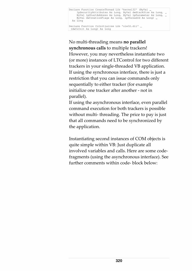
Declare Function CreateThread Lib "kernel32" (ByVal _ lpSecurityAttributes As Long, ByVal dwStackSize As Long, _ ByVal lpStartAddress As Long, ByVal lpParameter As Long, _ ByVal dwCreationFlags As Long, lpThreadId As Long) _ As Long Declare Function CoInitialize Lib "ole32.dll" _ (dwCoInit As Long) As Long
No multi‐threading means no parallel synchronous calls to multiple trackers! However, you may nevertheless instantiate two (or more) instances of LTControl for two different trackers in your single‐threaded VB application. If using the synchronous interface, there is just a restriction that you can issue commands only sequentially to either tracker (for example initialize one tracker after another ‐ not in parallel). If using the asynchronous interface, even parallel command execution for both trackers is possible without multi‐ threading. The price to pay is just that all commands need to be synchronized by the application. Instantiating second instances of COM objects is quite simple within VB: Just duplicate all involved variables and calls. Here are some code‐ fragments (using the asynchronous interface). See further comments within code‐ block below:
320
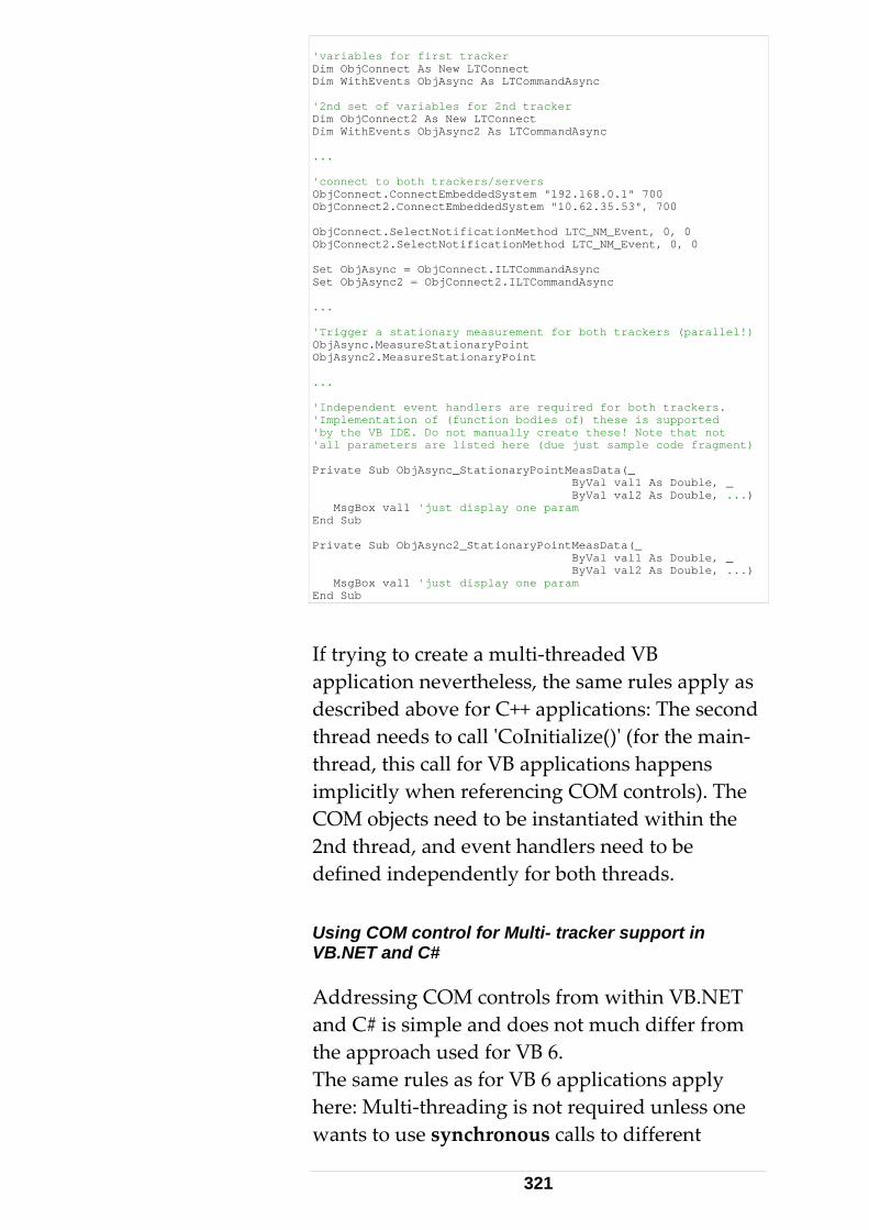
'variables for first tracker Dim ObjConnect As New LTConnect Dim WithEvents ObjAsync As LTCommandAsync '2nd set of variables for 2nd tracker Dim ObjConnect2 As New LTConnect Dim WithEvents ObjAsync2 As LTCommandAsync ... 'connect to both trackers/servers ObjConnect.ConnectEmbeddedSystem "192.168.0.1" 700 ObjConnect2.ConnectEmbeddedSystem "10.62.35.53", 700 ObjConnect.SelectNotificationMethod LTC_NM_Event, 0, 0 ObjConnect2.SelectNotificationMethod LTC_NM_Event, 0, 0 Set ObjAsync = ObjConnect.ILTCommandAsync Set ObjAsync2 = ObjConnect2.ILTCommandAsync ... 'Trigger a stationary measurement for both trackers (parallel!) ObjAsync.MeasureStationaryPoint ObjAsync2.MeasureStationaryPoint ... 'Independent event handlers are required for both trackers. 'Implementation of (function bodies of) these is supported 'by the VB IDE. Do not manually create these! Note that not 'all parameters are listed here (due just sample code fragment) Private Sub ObjAsync_StationaryPointMeasData(_ ByVal val1 As Double, _ ByVal val2 As Double, ...) MsgBox val1 'just display one param End Sub Private Sub ObjAsync2_StationaryPointMeasData(_ ByVal val1 As Double, _ ByVal val2 As Double, ...) MsgBox val1 'just display one param End Sub
If trying to create a multi‐threaded VB application nevertheless, the same rules apply as described above for C++ applications: The second thread needs to call ʹCoInitialize()ʹ (for the main‐ thread, this call for VB applications happens implicitly when referencing COM controls). The COM objects need to be instantiated within the 2nd thread, and event handlers need to be defined independently for both threads. Using COM control for Multi- tracker support in VB.NET and C# Addressing COM controls from within VB.NET and C# is simple and does not much differ from the approach used for VB 6. The same rules as for VB 6 applications apply here: Multi‐threading is not required unless one wants to use synchronous calls to different
321
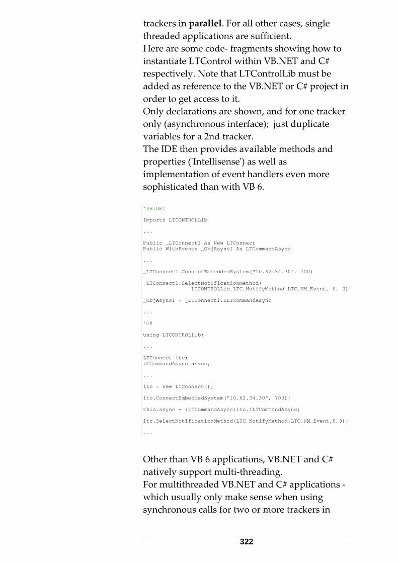
trackers in parallel. For all other cases, single threaded applications are sufficient. Here are some code‐ fragments showing how to instantiate LTControl within VB.NET and C# respectively. Note that LTControlLib must be added as reference to the VB.NET or C# project in order to get access to it. Only declarations are shown, and for one tracker only (asynchronous interface); just duplicate variables for a 2nd tracker. The IDE then provides available methods and properties (ʹIntellisenseʹ) as well as implementation of event handlers even more sophisticated than with VB 6. 'VB.NET Imports LTCONTROLLib ... Public _LTConnect1 As New LTConnect Public WithEvents _ObjAsync1 As LTCommandAsync ... _LTConnect1.ConnectEmbeddedSystem("10.62.34.30", 700) _LTConnect1.SelectNotificationMethod( _ LTCONTROLLib.LTC_NotifyMethod.LTC_NM_Event, 0, 0) _ObjAsync1 = _LTConnect1.ILTCommandAsync ... 'C# using LTCONTROLLib; ... LTConnect ltc; LTCommandAsync async; ... ltc = new LTConnect(); ltc.ConnectEmbeddedSystem("10.62.34.30", 700); this.async = (LTCommandAsync)ltc.ILTCommandAsync; ltc.SelectNotificationMethod(LTC_NotifyMethod.LTC_NM_Event,0,0); ...
Other than VB 6 applications, VB.NET and C# natively support multi‐threading. For multithreaded VB.NET and C# applications ‐ which usually only make sense when using synchronous calls for two or more trackers in
322
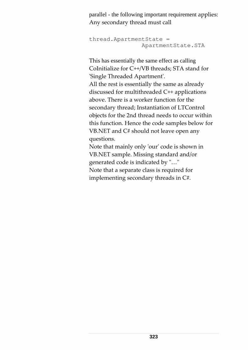
parallel - the following important requirement applies: Any secondary thread must call thread.ApartmentState = ApartmentState.STA This has essentially the same effect as calling CoInitialize for C++/VB threads; STA stand for ʹSingle Threaded Apartmentʹ. All the rest is essentially the same as already discussed for multithreaded C++ applications above. There is a worker function for the secondary thread; Instantiation of LTControl objects for the 2nd thread needs to occur within this function. Hence the code samples below for VB.NET and C# should not leave open any questions. Note that mainly only ʹourʹ code is shown in VB.NET sample. Missing standard and/or generated code is indicated by ʺ…ʺ Note that a separate class is required for implementing secondary threads in C#.
323
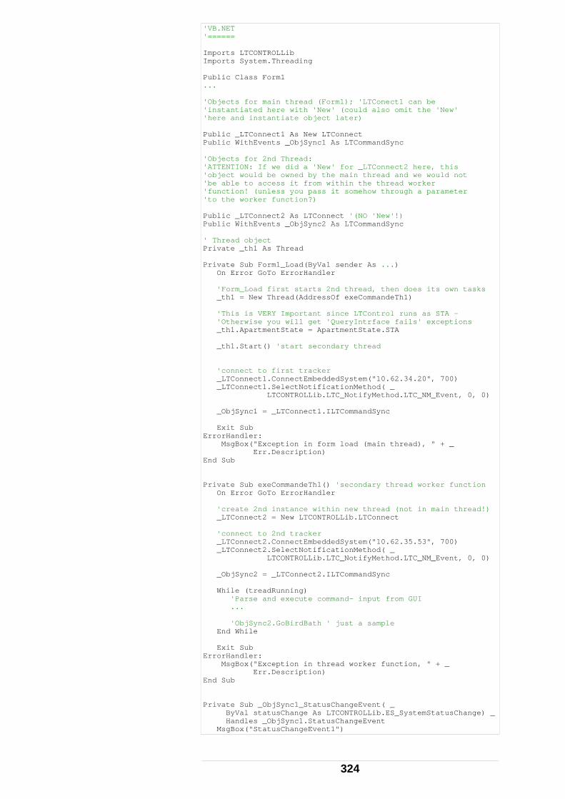
'VB.NET '====== Imports LTCONTROLLib Imports System.Threading Public Class Form1 ... 'Objects for main thread (Form1); 'LTConect1 can be 'instantiated here with 'New' (could also omit the 'New' 'here and instantiate object later) Public _LTConnect1 As New LTConnect Public WithEvents _ObjSync1 As LTCommandSync 'Objects for 2nd Thread: 'ATTENTION: If we did a 'New' for _LTConnect2 here, this 'object would be owned by the main thread and we would not 'be able to access it from within the thread worker 'function! (unless you pass it somehow through a parameter 'to the worker function?) Public _LTConnect2 As LTConnect '(NO 'New'!) Public WithEvents _ObjSync2 As LTCommandSync ' Thread object Private _th1 As Thread Private Sub Form1_Load(ByVal sender As ...) On Error GoTo ErrorHandler 'Form_Load first starts 2nd thread, then does its own tasks _th1 = New Thread(AddressOf exeCommandeTh1) 'This is VERY Important since LTControl runs as STA - 'Otherwise you will get 'QueryIntrface fails' exceptions _th1.ApartmentState = ApartmentState.STA _th1.Start() 'start secondary thread 'connect to first tracker _LTConnect1.ConnectEmbeddedSystem("10.62.34.20", 700) _LTConnect1.SelectNotificationMethod( _ LTCONTROLLib.LTC_NotifyMethod.LTC_NM_Event, 0, 0) _ObjSync1 = _LTConnect1.ILTCommandSync Exit Sub ErrorHandler: MsgBox("Exception in form load (main thread), " + _ Err.Description) End Sub Private Sub exeCommandeTh1() 'secondary thread worker function On Error GoTo ErrorHandler 'create 2nd instance within new thread (not in main thread!) _LTConnect2 = New LTCONTROLLib.LTConnect 'connect to 2nd tracker _LTConnect2.ConnectEmbeddedSystem("10.62.35.53", 700) _LTConnect2.SelectNotificationMethod( _ LTCONTROLLib.LTC_NotifyMethod.LTC_NM_Event, 0, 0) _ObjSync2 = _LTConnect2.ILTCommandSync While (treadRunning) 'Parse and execute command- input from GUI ... 'ObjSync2.GoBirdBath ' just a sample End While Exit Sub ErrorHandler: MsgBox("Exception in thread worker function, " + _ Err.Description) End Sub Private Sub _ObjSync1_StatusChangeEvent( _ ByVal statusChange As LTCONTROLLib.ES_SystemStatusChange) _ Handles _ObjSync1.StatusChangeEvent MsgBox("StatusChangeEvent1")
324
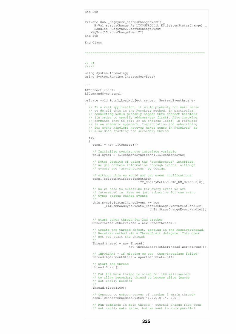
End Sub Private Sub _ObjSync2_StatusChangeEvent( _ ByVal statusChange As LTCONTROLLib.ES_SystemStatusChange) _ Handles _ObjSync2.StatusChangeEvent MsgBox("StatusChangeEvent2") End Sub End Class --------------------------------------------------------------- // C# ///// using System.Threading; using System.Runtime.InteropServices; ... LTConnect conn1; LTCommandSync sync1; private void Form1_Load(object sender, System.EventArgs e) { // In a real application, it would probably not make sense // to do all this in the FormLoad method. In particular, // connecting would probably happen thru connect handlers // (in order to specify address(es) first). Also invoking // commands (not to tall of an endless loop!) in FormLoad // is an academic approach. Instantiation and subscribing // for event handlers however makes sense in FormLoad, as // also does starting the secondary thread try { conn1 = new LTConnect(); // Initialize synchronous interface variable this.sync1 = (LTCommandSync)conn1.ILTCommandSync; // Note: Despite of using the 'synchronous' interface, // we get certain information through events, although // events are 'asynchronous' by design. // without this we would not get event notifications conn1.SelectNotificationMethod( LTC_NotifyMethod.LTC_NM_Event,0,0); // So we need to subscribe for every event we are // interested in. Here we just subscribe for one event // type: status change events // this.sync1.StatusChangeEvent += new _ILTCommandSyncEvents_StatusChangeEventEventHandler( this.StausChangeEventHandler); // start other thread for 2nd tracker OtherThread otherThread = new OtherThread(); // Create the thread object, passing in the ReceiverThread. // Receiver method via a ThreadStart delegate. This does // not yet start the thread. // Thread thread = new Thread( new ThreadStart(otherThread.WorkerFunc)); // IMPORTANT - if missing we get 'QueryInterface failed' thread.ApartmentState = ApartmentState.STA; // Start the thread thread.Start(); // Put the Main thread to sleep for 100 millisecond // to allow secondary thread to become alive (maybe // not really needed) // Thread.Sleep(100); // Connect to emScon server of tracker 1 (main thread) conn1.ConnectEmbeddedSystem("127.0.0.1", 700); // Run commands in main thread - eternal change face does // not really make sense, but we want to show parallel
325
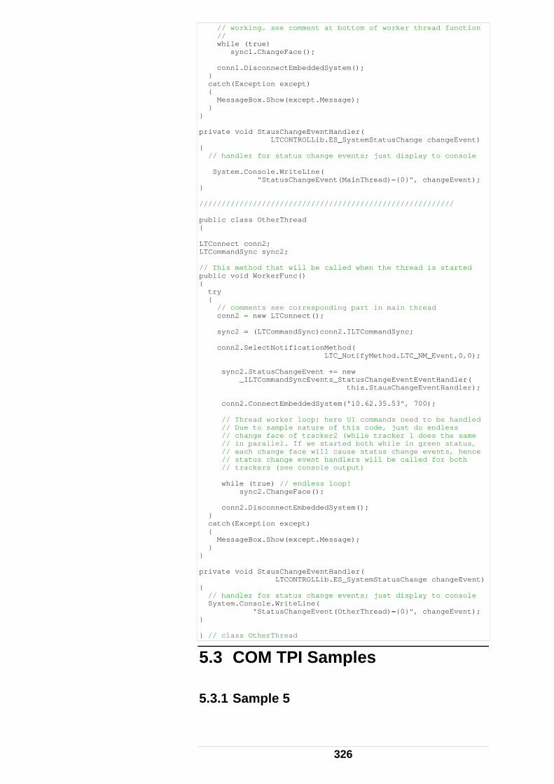
// working. see comment at bottom of worker thread function // while (true) sync1.ChangeFace(); conn1.DisconnectEmbeddedSystem(); } catch(Exception except) { MessageBox.Show(except.Message); } } private void StausChangeEventHandler( LTCONTROLLib.ES_SystemStatusChange changeEvent) { // handler for status change events; just display to console System.Console.WriteLine( "StatusChangeEvent(MainThread)={0}", changeEvent); } ///////////////////////////////////////////////////////// public class OtherThread { LTConnect conn2; LTCommandSync sync2; // This method that will be called when the thread is started public void WorkerFunc() { try { // comments see corresponding part in main thread conn2 = new LTConnect(); sync2 = (LTCommandSync)conn2.ILTCommandSync; conn2.SelectNotificationMethod( LTC_NotifyMethod.LTC_NM_Event,0,0); sync2.StatusChangeEvent += new _ILTCommandSyncEvents_StatusChangeEventEventHandler( this.StausChangeEventHandler); conn2.ConnectEmbeddedSystem("10.62.35.53", 700); // Thread worker loop; here UI commands need to be handled // Due to sample nature of this code, just do endless // change face of tracker2 (while tracker 1 does the same // in parallel. If we started both while in green status, // each change face will cause status change events, hence // status change event handlers will be called for both // trackers (see console output) while (true) // endless loop! sync2.ChangeFace(); conn2.DisconnectEmbeddedSystem(); } catch(Exception except) { MessageBox.Show(except.Message); } } private void StausChangeEventHandler( LTCONTROLLib.ES_SystemStatusChange changeEvent) { // handler for status change events; just display to console System.Console.WriteLine( "StatusChangeEvent(OtherThread)={0}", changeEvent); } } // class OtherThread
5.3 COM TPI Samples 5.3.1 Sample 5
326
This chapter is related to the ʹSample5ʹ folder of the emScon SDK Samples.
Sample 5 (LtcVBClient) comes as an LTControl‐based Visual Basic emScon Client.
Note: ʹLTControl.dllʹ must be correctly registered before proceeding.
See chapter ʹLTControl.dll Installation' for details.
If LTControl is correctly registered, ʹLtcVBClient.vbpʹ can directly be opened with Visual Basic Studio. It should be ready to compile and run.
In order to create a Sample 5‐ type application from scratch, follow the steps:
- Launch Visual Basic 6.0, choose New Project > Standard exe. Click OK.
- Save the default Form1 as LtcVBClient.frm and the project as LtcVBClient.vbp (or use any name of your choice).
- Choose menu Project > References.
- In the ʹAvailable Referencesʹ list, look for the entry ʹLTControl 2.x Type Libraryʹ and check the box in front of. Ensure that the file path at the bottom of the dialog matches the controlʹs registration location. Otherwise browse for the correct location. Finally click OK.
Accessing COM Interfaces
Other than ActiveX (OCX) controls, LTControl.dll, which is an ATL‐type COM object, can also be used for non‐window based applications. For example, it will also support, pure C‐clients (console applications).
It is neither necessary nor possible to place an LTControl control object to the VB application
327
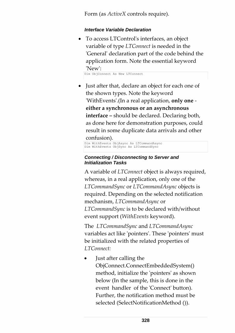
Form (as ActiveX controls require). Interface Variable Declaration
• To access LTControlʹs interfaces, an object variable of type LTConnect is needed in the ʹGeneralʹ declaration part of the code behind the application form. Note the essential keyword ʹNewʹ: Dim ObjConnect As New LTConnect
• Just after that, declare an object for each one of the shown types. Note the keyword ʹWithEventsʹ.(In a real application, only one ‐ either a synchronous or an asynchronous interface – should be declared. Declaring both, as done here for demonstration purposes, could result in some duplicate data arrivals and other confusion). Dim WithEvents ObjAsync As LTCommandAsync Dim WithEvents ObjSync As LTCommandSync
Connecting / Disconnecting to Server and Initialization Tasks
A variable of LTConnect object is always required, whereas, in a real application, only one of the LTCommandSync or LTCommandAsync objects is required. Depending on the selected notification mechanism, LTCommandAsync or LTCommandSync is to be declared with/without event support (WithEvents keyword).
The LTCommandSync and LTCommandAsync variables act like ʹpointersʹ. These ʹpointersʹ must be initialized with the related properties of LTConnect:
• Just after calling the ObjConnect.ConnectEmbeddedSystem() method, initialize the ʹpointersʹ as shown below (In the sample, this is done in the event handler of the ʹConnectʹ button). Further, the notification method must be selected (SelectNotificationMethod ()).
328
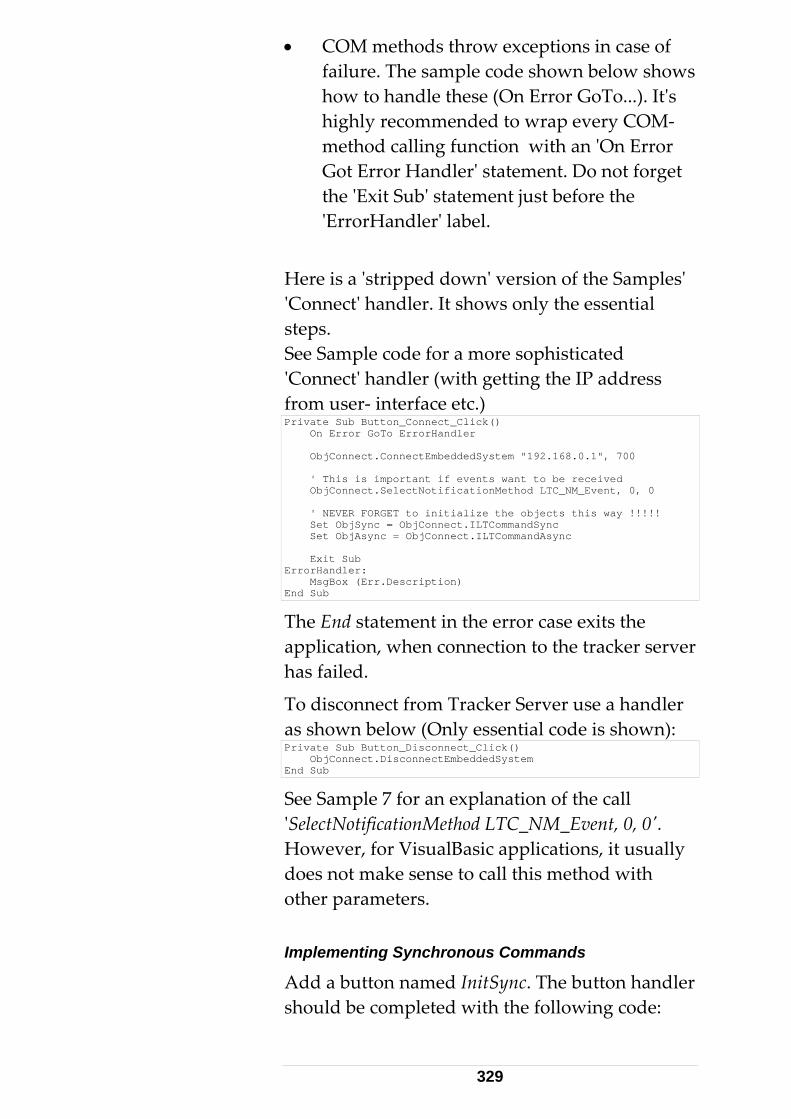
• COM methods throw exceptions in case of failure. The sample code shown below shows how to handle these (On Error GoTo...). Itʹs highly recommended to wrap every COM‐ method calling function with an ʹOn Error Got Error Handlerʹ statement. Do not forget the ʹExit Subʹ statement just before the ʹErrorHandlerʹ label.
Here is a ʹstripped downʹ version of the Samplesʹ ʹConnectʹ handler. It shows only the essential steps. See Sample code for a more sophisticated ʹConnectʹ handler (with getting the IP address from user‐ interface etc.) Private Sub Button_Connect_Click() On Error GoTo ErrorHandler ObjConnect.ConnectEmbeddedSystem "192.168.0.1", 700 ' This is important if events want to be received ObjConnect.SelectNotificationMethod LTC_NM_Event, 0, 0 ' NEVER FORGET to initialize the objects this way !!!!! Set ObjSync = ObjConnect.ILTCommandSync Set ObjAsync = ObjConnect.ILTCommandAsync Exit Sub ErrorHandler: MsgBox (Err.Description) End Sub
The End statement in the error case exits the application, when connection to the tracker server has failed.
To disconnect from Tracker Server use a handler as shown below (Only essential code is shown): Private Sub Button_Disconnect_Click() ObjConnect.DisconnectEmbeddedSystem End Sub
See Sample 7 for an explanation of the call ʹSelectNotificationMethod LTC_NM_Event, 0, 0ʹ. However, for VisualBasic applications, it usually does not make sense to call this method with other parameters. Implementing Synchronous Commands
Add a button named InitSync. The button handler should be completed with the following code:
329
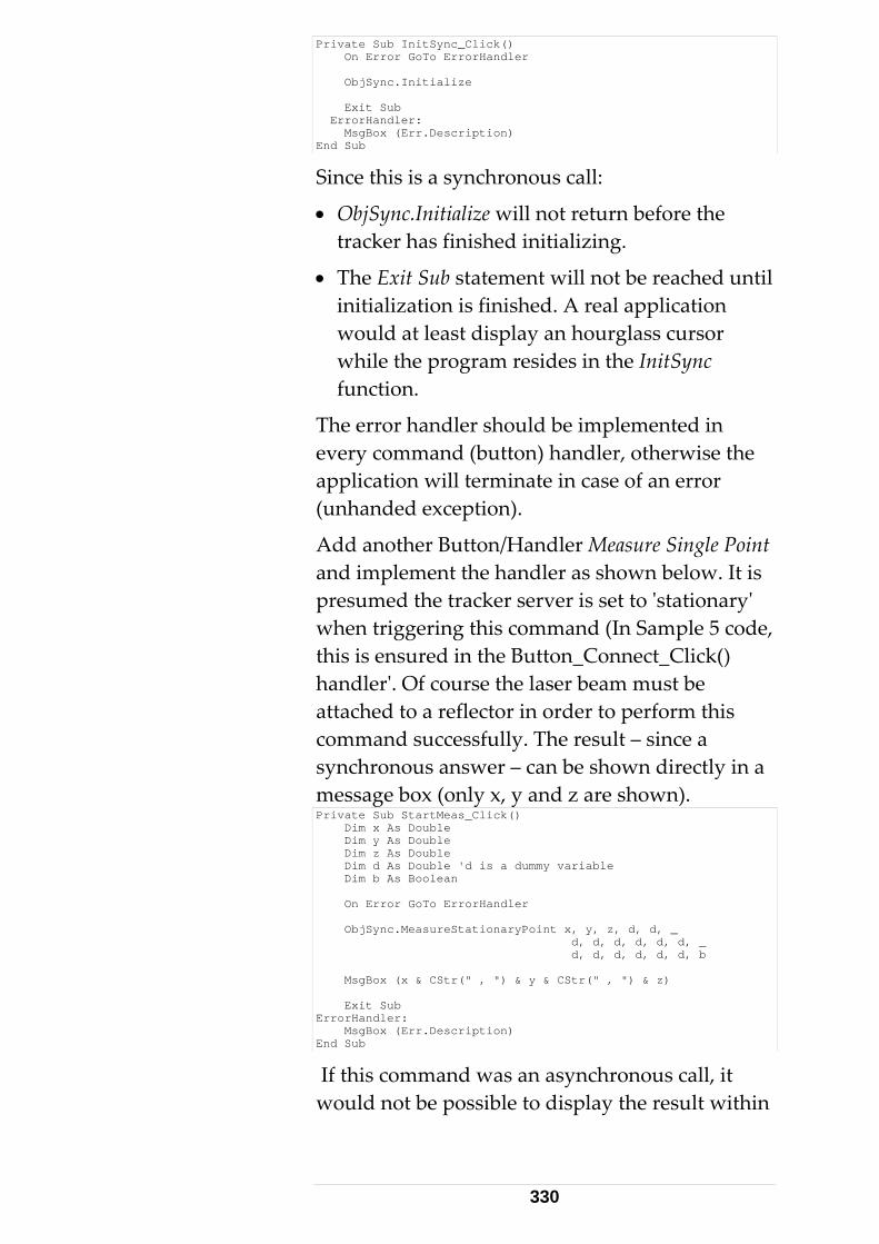
Private Sub InitSync_Click() On Error GoTo ErrorHandler ObjSync.Initialize Exit Sub ErrorHandler: MsgBox (Err.Description) End Sub
Since this is a synchronous call:
• ObjSync.Initialize will not return before the tracker has finished initializing.
• The Exit Sub statement will not be reached until initialization is finished. A real application would at least display an hourglass cursor while the program resides in the InitSync function.
The error handler should be implemented in every command (button) handler, otherwise the application will terminate in case of an error (unhanded exception).
Add another Button/Handler Measure Single Point and implement the handler as shown below. It is presumed the tracker server is set to ʹstationaryʹ when triggering this command (In Sample 5 code, this is ensured in the Button_Connect_Click() handlerʹ. Of course the laser beam must be attached to a reflector in order to perform this command successfully. The result – since a synchronous answer – can be shown directly in a message box (only x, y and z are shown). Private Sub StartMeas_Click() Dim x As Double Dim y As Double Dim z As Double Dim d As Double 'd is a dummy variable Dim b As Boolean On Error GoTo ErrorHandler ObjSync.MeasureStationaryPoint x, y, z, d, d, _ d, d, d, d, d, d, _ d, d, d, d, d, d, b MsgBox (x & CStr(" , ") & y & CStr(" , ") & z) Exit Sub ErrorHandler: MsgBox (Err.Description) End Sub
If this command was an asynchronous call, it would not be possible to display the result within
330
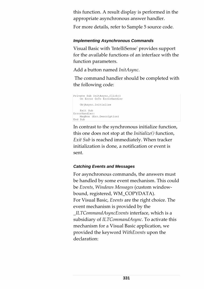
this function. A result display is performed in the appropriate asynchronous answer handler.
For more details, refer to Sample 5 source code. Implementing Asynchronous Commands
Visual Basic with ʹIntelliSenseʹ provides support for the available functions of an interface with the function parameters.
Add a button named InitAsync.
The command handler should be completed with the following code: Private Sub InitAsync_Click() On Error GoTo ErrorHandler ObjAsync.Initialize Exit Sub ErrorHandler: MsgBox (Err.Description) End Sub
In contrast to the synchronous initialize function, this one does not stop at the Initialize() function, Exit Sub is reached immediately. When tracker initialization is done, a notification or event is sent. Catching Events and Messages
For asynchronous commands, the answers must be handled by some event mechanism. This could be Events, Windows Messages (custom window‐bound, registered, WM_COPYDATA). For Visual Basic, Events are the right choice. The event mechanism is provided by the _ILTCommandAsyncEvents interface, which is a subsidiary of ILTCommandAsync. To activate this mechanism for a Visual Basic application, we provided the keyword WithEvents upon the declaration:
331
Dim WithEvents ObjAsync As LTCommandAsync
When no requirements for catching events exists, omit the WithEvents keywords in order to save overhead.
Not only the asynchronous interface – where absolutely crucial – has an Event interface. Also the synchronous interface has an Event interface, _ILTCommandSyncEvents. It is required for receiving continuous measurements and other ʹmulti‐ answerʹ results (such as results to a ʹGetReflectorsʹ call), as well as for error messages (such as beam broken events), which cannot be handled synchronous by their nature.
Events are one of the notification methods of the LT Control. When alternatively using Windows messages for asynchronous notifications the keyword WithEvents becomes obsolete. Windows messages (instead of Events) may be more appropriate for VC++ clients and will be discussed later. For VisualBasic, Events are always the right choice.
• The application must declare what notification mechanism to use. We did this with the statement shown below. Without calling this function in the initialization part of the application, no notification mechanism will be activated. See remarks on continuous measurement in chapter ʹHandling Data Arrival – Continuous Measurements'.
ObjConnect.SelectNotificationMethod LTC_NM_Event, 0, 0
• As soon as the WithEvents keyword is declared, the ObjAsync object (or whatever the variable is called) is listed in the top left list box of the Formʹs source code window. Just as an experiment: Remove WithEvents and save the code – the list entry will vanish.
332
• If ObjAsync is selected in the list box, a list of all available event handlers is shown in the right drop‐down list.
• To generate the code framework for an event handler, select it from the right list .
Selecting ErrorEvent will generate a function named ObjAsync_ErrorEvent. Do this and complete the generated function frame with a message box to read as follows: Private Sub ObjSync_ErrorEvent( _ ByVal command As LTCONTROLLib.ES_Command, _ ByVal status As LTCONTROLLib.ES_ResultStatus) MsgBox (command & CStr(" , ") & status) End Sub
This event handler will now be triggered, for example on a Beam Broken Event. Note: The 6Dof part of the interface contains some event‐ types with a huge count of parameters. To mention ‘StationaryProbeMeasData’, which is the most extreme with 49 parameters (!)
Such excessive parameter lists – depending on VB version ‐ partly are beyond code‐ generating Wizards capability. Lines may be cut, which will lead to syntax errors (for generated code). In these cases, the cut lines need to be completed manually (see type‐library for signature). Extended Synchronous Functions
ObjSync.MeasurStationaryPoint has 18 (basic data type) parameters. Basic data type parameters are a requirement in order to use these functions with (older versions of) VBA (Excel, Access…). For programming languages supporting user‐defined data types (VC++, Visual Basic), having a function with only one struct parameter would be more convenient. LTControl provides a collection of such ʹextendedʹ functions.
333
Note that such extended functions cannot be provided for Event handlers (Technical limitation)
One of these extended functions, MeasureStationaryPointEx, is implemented in the sample: Private Sub StartMeasEx_Click() Dim result As SingleMeasResultT On Error GoTo ErrorHandler ObjSync. MeasureStationaryPointEx result ' display the result MsgBox(result.packetInfo.status & CStr(" , ") & _ result.packetInfo.packetHeader.Type & _ CStr(" , ") & result.dVal1 & CStr(" , ") & _ result.dVal2 & CStr(" , ") & result.dVal3) Exit Sub ErrorHandler: MsgBox (Err.Description) End Sub
The data type SingleMeasResultT from the C‐TPI is transparent through the COM interface. The VB application ʹknowsʹ this type, through its reference to the LTControl.
Remark
Do not test explicitly against the VB keyword ʹTrueʹ, if using the Get<FunctionName>Ex methods of the LTControl, for those commands returning Boolean data within their result structure. This is because the Boolean member in these structures – if true – are (1). However, the VB keyword ʹTrueʹ evaluates to (‐1).
Always test the variable directly, or against ʹNot Falseʹ.
334
Example Dim dataout As ContinuousDistanceModeDataT ObjSync.GetContinuousDistanceModeParamsEx dataout If (dataout.bUseRegion) Then MsgBox "bUseRegion is True" End If or If Not (dataout.bUseRegion = False) Then MsgBox "bUseRegion is True" End If are both correct. However, the following would evaluate to a wrong result: If (dataout.bUseRegion = True) Then MsgBox "bUseRegion is True" ‘ No message even flag is true! End If
Further details see ʹReadme.txtʹ file in Sample 5 folder and code‐ comments in source files. 5.3.2 Sample 7 The LtcCPPClient provides a dialog‐ based MFC C++ application. It uses the synchronous interface, but also implements an event sink to catch asynchronous answers (continuous measurements and error events).
Programmers need to be familiar with ATL/COM in order to understand the event sink implementation.
Refer to a COM book for further details.
The LtcCPPClient covers all essential initial steps for a successful system start and accurate results, with some disabled code, which demonstrates all other variants of notification methods, which may be more familiar to programmers than event handling.
See comments in source code. Message Notifications
The disadvantages of message notifications are:
• The result parameters cannot be received directly.
335
• There are only general messages for all types of answers.
• Usually only the size of a data block is passed with the message.
• The data block must be first read with GetData() (except for WM_COPYDATA) and then interpreted. Interpretation is done with a ʹswitchʹ statement with the ProcessData() sample code.
See chapter ʹHandling Data Arrival – Continuous Measurements ʹ. See also Sample4 / Step5: This sample uses directly the emScon C++ interface (rather than COM from C++, like Sample7 does)
This sample also shows one of the features not shown so far: How to retrieve the reflectors known to the system. It also demonstrates continuous measurements.
View the source code for details. Note that this code contains a relatively big overhead needed for user interface issues. The Tracker Server specific part is not that dominant. Source Code Description
• Information that is displayed in list boxes, such as units, CS‐type, is automatically read from the Tracker Server upon startup. What is seen has been actually selected.
• Changing the items of one list box automatically creates a ʹSetʹ for the newly selected item.
• On changing units, CS‐type etc., some dependent information may vanish from the related edit fields to ensure consistency. This is due to the paradigm ʹWhat you see is selectedʹ. Do a ʹGetʹ to recover it, which can also be done by the application.
336
• On setting new values, the ʹSetʹ command is automatically followed by a ʹGetʹ (two beep sounds). The ʹGetʹ is not required (only for testing and demonstration purpose).
• Reflectors are read upon client startup. Can be heard by characteristic beeps. They must be selected in the reflectors list box. The GetReflectors button is only required in ʹemergencyʹ cases. If the client starts before the Tracker Server is ready and the client dialog shows up, but is not able to read the reflectors yet.
• The application is based on LTC_NM_Event notification selection. By changing the parameter of SelectNotificationMethod in CCPPClientDlg::OnInitDialog() (all variants are prepared), a different notification method can be activated. However, there is only an incomplete implementation of ProcessData() for these alternate methods (reflector processing, for example, is not yet complete).
• Only the LTC_NM_Event notification method is fully implemented in this sample. However, data transfer also works with message methods. One or the other methods can be activated by enabling the commented source code. Only the last call of SelectNotificationMethod is effective (there should be only one call to this function). See chapter ʹHandling Data Arrival – Continuous Measurementsʹ for details on obtaining data in general and continuous measurements in particular.
Handling Data Arrival – Continuous Measurements
Continuous measurement streams are always handled asynchronous. That is, even if only a LTCommandSync is implemented (through which
337
the Start Measurement command may be invoked), the continuous measurement packets will arrive asynchronously.
A continuous measurement may last very long. It is not suitable to block execution all the time.
Methods to Catch Packets
• Provide a LTCommandSync object with a call to SelectNotificationMethod, with LTC_NM_Event as first parameter. This setting allows catching the continuous measurement packets through the event mechanism. This is especially convenient for Visual Basic.
• Use one of the Windows Messages notification methods. See ʹSample 7ʹ – where this method is shown (disabled) in the source code. These may be methods preferred with VC++ clients, especially if the programmer is not familiar on setting up event sinks. On the other hand, receiving Windows messages within VB application is permissible.
• The MultiMeasResultT structure only covers the first item of the array. The rest of the lNumberOfResults ‐ 1‐array elements are padded to the packet without gaps. Continuous measurement packets mostly contain more than one measurement value. Iteration through an array of measurements is necessary.
• A code fragment, on how to process a continuous measurement packet using the event mechanism, is shown below. This is a client implementation, stripped down and altered from sample 7, of the ContinuousPointMeasDataReady event, which exists for both _ILTCommandSyncEvents and _ILTCommandAsyncEvents interfaces
338
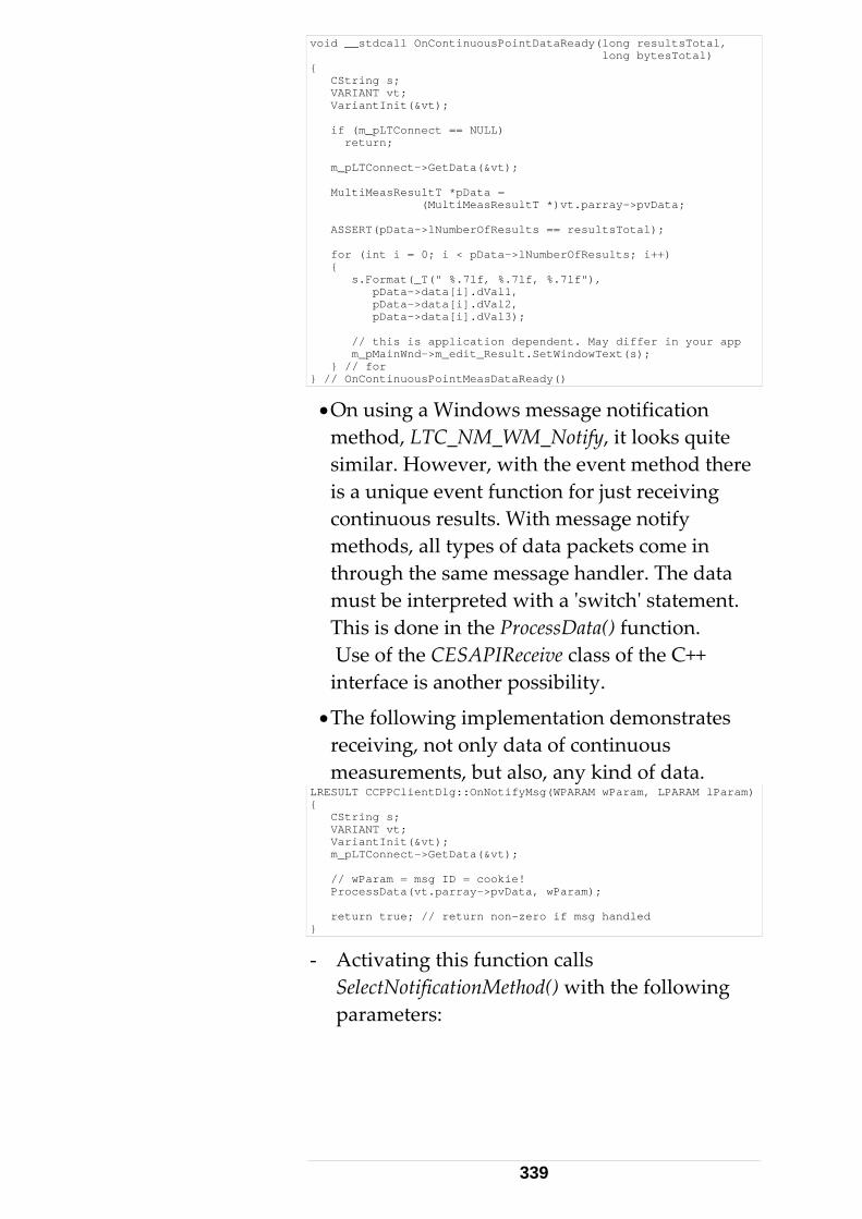
void __stdcall OnContinuousPointDataReady(long resultsTotal, long bytesTotal) { CString s; VARIANT vt; VariantInit(&vt); if (m_pLTConnect == NULL) return; m_pLTConnect->GetData(&vt); MultiMeasResultT *pData = (MultiMeasResultT *)vt.parray->pvData; ASSERT(pData->lNumberOfResults == resultsTotal); for (int i = 0; i < pData->lNumberOfResults; i++) { s.Format(_T(" %.7lf, %.7lf, %.7lf"), pData->data[i].dVal1, pData->data[i].dVal2, pData->data[i].dVal3); // this is application dependent. May differ in your app m_pMainWnd->m_edit_Result.SetWindowText(s); } // for } // OnContinuousPointMeasDataReady()
• On using a Windows message notification method, LTC_NM_WM_Notify, it looks quite similar. However, with the event method there is a unique event function for just receiving continuous results. With message notify methods, all types of data packets come in through the same message handler. The data must be interpreted with a ʹswitchʹ statement. This is done in the ProcessData() function. Use of the CESAPIReceive class of the C++ interface is another possibility.
• The following implementation demonstrates receiving, not only data of continuous measurements, but also, any kind of data.
LRESULT CCPPClientDlg::OnNotifyMsg(WPARAM wParam, LPARAM lParam) { CString s; VARIANT vt; VariantInit(&vt); m_pLTConnect->GetData(&vt); // wParam = msg ID = cookie! ProcessData(vt.parray->pvData, wParam); return true; // return non-zero if msg handled }
- Activating this function calls SelectNotificationMethod() with the following parameters:
339
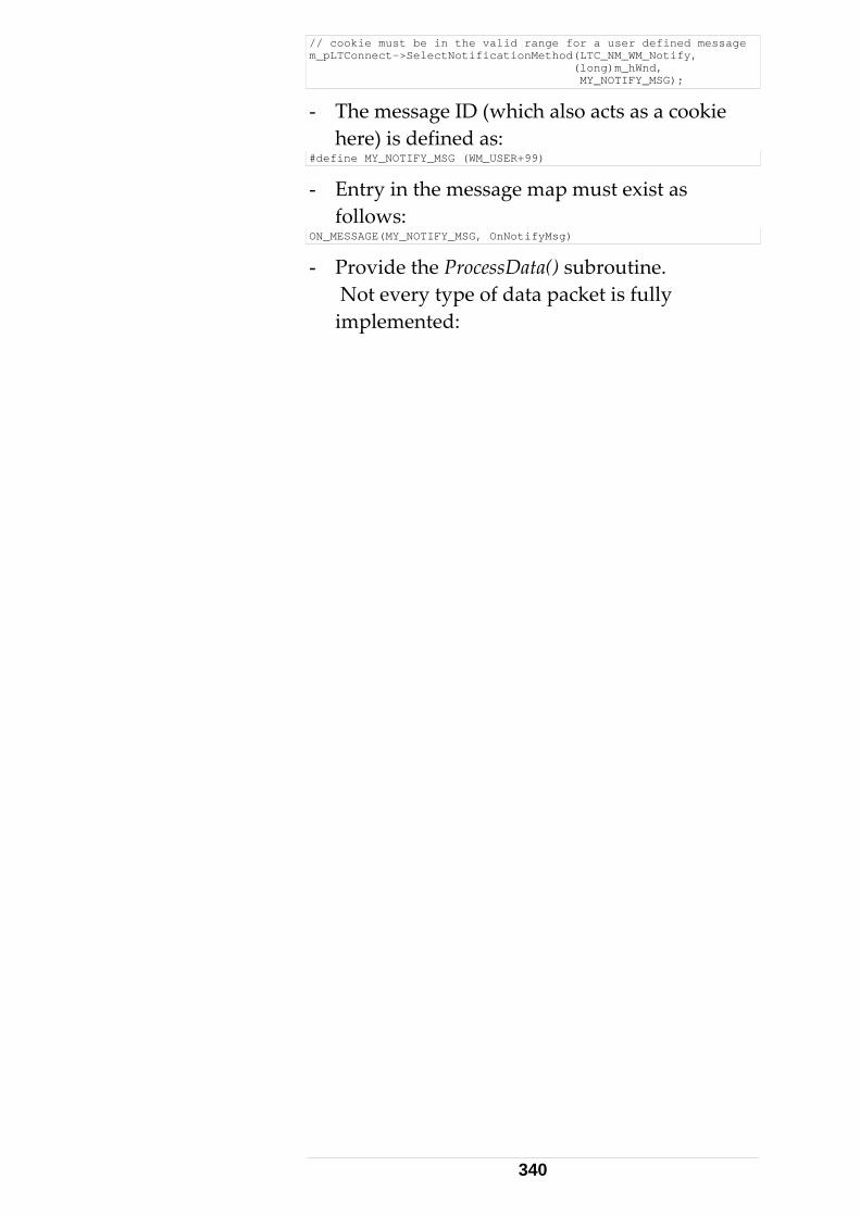
// cookie must be in the valid range for a user defined message m_pLTConnect->SelectNotificationMethod(LTC_NM_WM_Notify, (long)m_hWnd, MY_NOTIFY_MSG);
- The message ID (which also acts as a cookie here) is defined as:
#define MY_NOTIFY_MSG (WM_USER+99)
- Entry in the message map must exist as follows:
ON_MESSAGE(MY_NOTIFY_MSG, OnNotifyMsg)
- Provide the ProcessData() subroutine. Not every type of data packet is fully implemented:
340
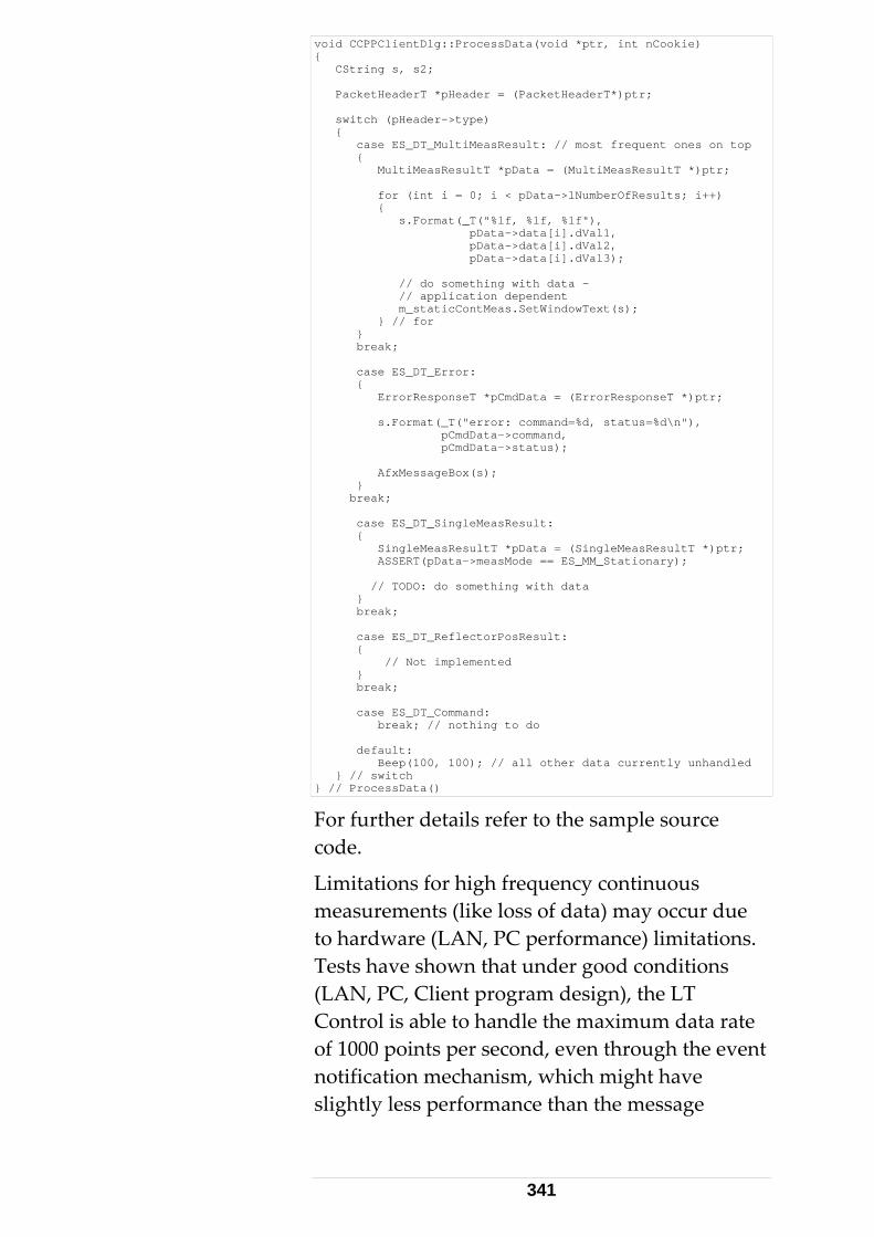
void CCPPClientDlg::ProcessData(void *ptr, int nCookie) { CString s, s2; PacketHeaderT *pHeader = (PacketHeaderT*)ptr; switch (pHeader->type) { case ES_DT_MultiMeasResult: // most frequent ones on top { MultiMeasResultT *pData = (MultiMeasResultT *)ptr; for (int i = 0; i < pData->lNumberOfResults; i++) { s.Format(_T("%lf, %lf, %lf"), pData->data[i].dVal1, pData->data[i].dVal2, pData->data[i].dVal3); // do something with data - // application dependent m_staticContMeas.SetWindowText(s); } // for } break; case ES_DT_Error: { ErrorResponseT *pCmdData = (ErrorResponseT *)ptr; s.Format(_T("error: command=%d, status=%d\n"), pCmdData->command, pCmdData->status); AfxMessageBox(s); } break; case ES_DT_SingleMeasResult: { SingleMeasResultT *pData = (SingleMeasResultT *)ptr; ASSERT(pData->measMode == ES_MM_Stationary); // TODO: do something with data } break; case ES_DT_ReflectorPosResult: { // Not implemented } break; case ES_DT_Command: break; // nothing to do default: Beep(100, 100); // all other data currently unhandled } // switch } // ProcessData()
For further details refer to the sample source code.
Limitations for high frequency continuous measurements (like loss of data) may occur due to hardware (LAN, PC performance) limitations. Tests have shown that under good conditions (LAN, PC, Client program design), the LT Control is able to handle the maximum data rate of 1000 points per second, even through the event notification mechanism, which might have slightly less performance than the message
341
methods – Low performance of IDispatch Interfaces.
Further details see ʹReadme.txtʹ file in Sample 7 folder and code‐ comments in source files.
Handling Continuous Measurements on using the emScon C++ interface directly (which is much more common than using the COM interface from a C++ application) can be found in Sample4/Step5. Other sources (for VB) can be found in Sample13. See Readme.txt files at the Samples locations. 5.3.3 Sample 8 This sample works only with Excel 2000 and higher, and consists of an Excel sheet with a VBA macro LtcExcel. Tracker server client VBA‐ programming with Excel 97 (Office 97) is not recommended. See chapter ʹVBA Macro‐Language Support (Excel, Word, Access) ʹ.
The essential difference between a VB client and an Excel client is that the Excel sheet takes the role of a VB Form. That is, data input/output goes through cells.
Further details see ʹReadme.txtʹ file in Sample 8 folder and code‐ comments in source files. 5.3.4 Sample 14 This sample shows integration of emScon COM TPI to a C# application. The focus of this sample is on how accessing COM methods from C#. An application just calling SetCameraParams / GetCameraParams (using synchronous interface) may not be very much related to practice.
This sample is preliminary an might be improved in future SDK versions.
342
Note: In order to build/run this sample, the .NET framework and VisualStudio V7 (VisualStudio.NET) is required.
Further details see ʹReadme.txtʹ file in Sample 14 folder and code‐ comments in source files. 5.3.5 Sample 15 This sample shows integration of emScon COM TPI to a VB .NET application. The focus of this sample is on how accessing COM methods from VB .NET. The application just demonstrates some system settings.
This sample is preliminary an might be improved in future SDK versions. Note: In order to build/run this sample, the .NET framework and VisualStudio V7 (VisualStudio.NET) is required.
Further details see ʹReadme.txtʹ file in Sample 15 folder and code‐ comments in source files. 5.3.6 Sample 18 LiveVideo display application. This sample is based on the ʹLTVideo2.ocxʹ ActiveX COM control. Attention: emScon 3.0 servers require Version 3.0 ʹLTVideo2.ocxʹ. This version of the control is backward compatible to older emScon servers.
See Chapter 8 / Special Functions / Live Image display for details. 5.3.7 Sample 20 Concerning its functionality, this sample is similar to Sample 5, i.e. an LTControl‐ based client. However, it is based on Borland Delphi 7 instead of Visual Basic.
343

If no Delphi 7 programming environment is available, you may download a trial version from Borlands homepage.
For details, refer to the ʹReadme.txtʹ file in the Sample20 folder and to heavily commented code.
344
6 C# - Interface
6.1 Client Programming with C# 6.1.1 Introduction The samples 14 and 15 (see chapter 4, COM‐ Interface) show how to embed the LTControl COM object into C# applications. However, there is also a C# class‐ interface similar to the C++ class‐ interface (shown in Sample16). Using the C# class interface is shown in Sample17.
In order to use this interface, the .NET framework and VisualStudio V7 (VisualStudio.NET) is required for client application programming. 6.1.2 C# Application Programming The C# class interface is represented through include file ʹES_MCPP_API_Def.hʹ (MCPP relates to ʹManaged C++). This file defines two abstract classes, ʹCESCSAPICommandʹ and ʹCESCSAPIReceiveʹ, from which a C# application must derive its own classes. This is quite the same approach as for the C++ interface. Note the name prefixes ʹCESCSAPIʹ (C#) versus ʹCESAPIʹ (C++). Since C# does not support the C++ like ʹinclude‐ fileʹ approach, the classes defined in ʹES_MCPP_API_Def.hʹ must be packed into a (Managed C++) DLL. This DLL then can be added as reference to a C# application.
345
For convenience, this DLL named ʹES_MCPP_API_Wrapper.dllʹ is also provided with the SDK (ES_SDK\Lib\Unicode).
If the DLL should be missing, or if it needs to be rebuilt due to changes in the ʹES_MCPP_API_Def.hʹ file, Sample 16 shows how to create this DLL. (Note: An emScon programmer may make changes to the files ʹES_MCPP_API_Def.hʹ and/or ʹES_CPP_API_Def.hʹ, although this should normally neither be necessary nor recommended)
Sample 17 shows a C# Application based on the emScon C# class interface. 6.1.3 Sample 16 This sample shows on how to create the required ʹES_MCPP_API_Wrapper.dllʹ from the ʹES_MCPP_API_Def.hʹ file.
This is quite simple: There is only one source file ʹES_MCPPAPIWrapper.cppʹ which contains nothing else than the statement #include "ES_MCPP_API_Def.h"
In addition, some well known emScon C‐ include files need to be provided in order to compile this project. (ES_C_API_Def.h, Enum.h etc.)
Note that the resulting DLL ʹES_MCPP_API_Wrapper.dllʹ has already been built and added to the SDK for convenience. It is therefore not really required to build it as shown in Sample16. However, Sample16 may help developers to debug their applications if code in ʹES_MCPP_API_Def.hʹ needs to be traced.
Further details see ʹReadme.txtʹ file in Sample 16 folder and code‐ comments in source files.
346
6.1.4 Sample 17 This sample implements a C# emScon application based on the C# class interface. The C++ interface cannot be used directly in C# applications. A specific C# class interface is therefore provided as described above. Note the difference to Samples 14/15, where the emScon COM interface was used. The one and the same COM object ca be used for C++ and C# as well as for visual basic, VBA (e.g. Excel) and VisualBasic.NET applications.
The programming approach is quite the same as for the C++ interface: Derive classes from both, ʹCESCSAPICommandʹ and ʹCESCSAPIReceiveʹ classes, override the ʹSendPacketʹ virtual function in ʹCESCSAPICommandʹ and override those virtual functions of ʹCESCSAPIReceiveʹ in which the application is interested in.
The application must provide Socket communication, and the same conditions as for C++ applications apply: Commands are invoked by calling ʹCESCSAPICommandʹ member functions and arriving data from the socket must be passed to the ʹCESCSAPIReceive::ReceiveDataʹ Parser. Note that only one packet at a time must be passed to the parser. The sample shows one possible approach: First always peek the packet header, then only read as many bytes as the ʹpacket‐ sizeʹ variable indicates. The helper method CESCSAPIReceive::GetPacketHeader() is useful in this context. There is a difference to the C++ interface concerning continuous measurements. If a continuous packet arrives, it contains only the measurement header info, but not the elementary measurements itself (like in C++ in a variable sized array). The application must rather use the CESCSAPIReceive :<MeasType>MeasValueGetA () function to access the measurements.
347
See code in sample 17 (file ʹEmsyCSApiConsoleClient.csʹ), for example in function ʹOnMultiMeasurementAnswer()ʹ for details.
As already known from C++ samples, sample 17 requires a separate Receiver Thread since it is a Console application. In Windows applications, the Window Message Loop can be used instead. Hence windows application do not require to be designed as multi threaded applications. See related C++ Windows emScon applications.
Make sure the ʹES_MCPP_API_Wrapper.dllʹ is added as reference to the project and that the reference path points to the correct location. (Sample 17 expects the DLL being in the applications runtime directory. However, this may be changed of course).
Sample 17 in not sophisticated in terms of error /exception handling and command synchronization. Remember that emScon commands are asynchronous and it is the applications responsibility not to send a new command to the server before the previous one has completed.
Answer‐ handlers (virtual overrides) for all types of answers are implemented. Also calls for all emScon commands are implemented, but all except one are commented in the sample code (any other call may be enabled instead). Due lack of synchronization, the provided sample application will mostly mess‐ up if sending more than one command.
The most simple way to synchronize the application was providing an old‐ style key‐press user‐ interface (as done in Sample 9). This means the user performs synchronization by not pressing the next key before the answer of the previous command has arrived.
348
See also the many comments in the code. This sample is preliminary an might be improved in future SDK versions. Further details see ʹReadme.txtʹ file in Sample 17 folder and code‐ comments in source files. 6.1.5 Multi- Tracker C# Applications Applications based on the ʹnativeʹ C# emScon interface behave much the same like applications based on the native C++ interface. The approach for multi‐tracker controlling is therefore very similar to whatʹs said under section 4 ʹWorking with multiple trackersʹ ‐ apart from the (language specific) differences that apply between C++ and C#. Multi‐ threading is neither required nor recommended in order to support multiple trackers (except if there is a Console‐ application, where multi‐ threading is required even for a single tracker application). Just designate an instance of a Sender and Receiver object to each one of the trackers (as described above for the C# interface and like applied in Sample 17). However, be aware that Sample 17 is a Console application and therefore requires multi‐threading by design. If it was an ordinary Windows application, we would not require receiver‐threads since the Windows messaging mechanism could be used for handling incoming data. Again: The secondary thread in Sample 17 (or even 2 of them if using 2 trackers) is NOT due to multiple tracker support; it is because a Console applications main thread blocks while waiting for user‐ input; hence we need a separate listener thread to process incoming data during blocking periods. Other than with the C++ SDK Samples, the Sender and Receiver classes of Sample 17 do not share any common data and therefore can just be
349
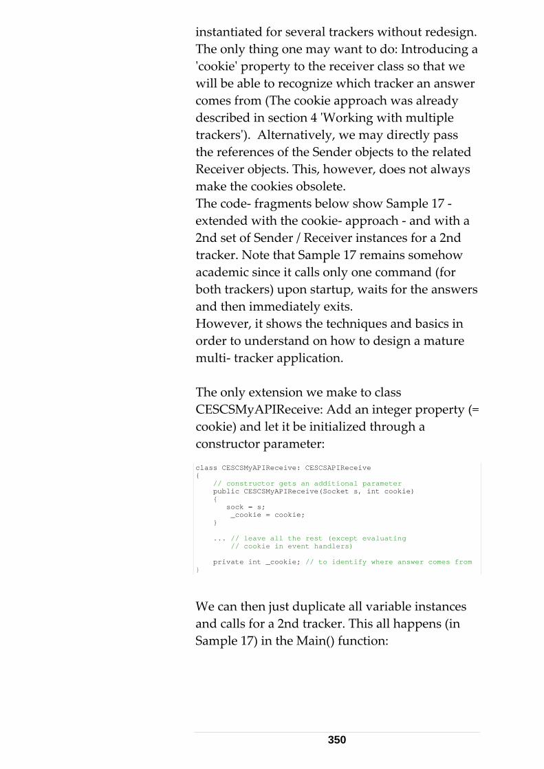
instantiated for several trackers without redesign. The only thing one may want to do: Introducing a ʹcookieʹ property to the receiver class so that we will be able to recognize which tracker an answer comes from (The cookie approach was already described in section 4 ʹWorking with multiple trackersʹ). Alternatively, we may directly pass the references of the Sender objects to the related Receiver objects. This, however, does not always make the cookies obsolete. The code‐ fragments below show Sample 17 ‐ extended with the cookie‐ approach ‐ and with a 2nd set of Sender / Receiver instances for a 2nd tracker. Note that Sample 17 remains somehow academic since it calls only one command (for both trackers) upon startup, waits for the answers and then immediately exits. However, it shows the techniques and basics in order to understand on how to design a mature multi‐ tracker application. The only extension we make to class CESCSMyAPIReceive: Add an integer property (= cookie) and let it be initialized through a constructor parameter: class CESCSMyAPIReceive: CESCSAPIReceive { // constructor gets an additional parameter public CESCSMyAPIReceive(Socket s, int cookie) { sock = s; _cookie = cookie; } ... // leave all the rest (except evaluating // cookie in event handlers) private int _cookie; // to identify where answer comes from }
We can then just duplicate all variable instances and calls for a 2nd tracker. This all happens (in Sample 17) in the Main() function:
350
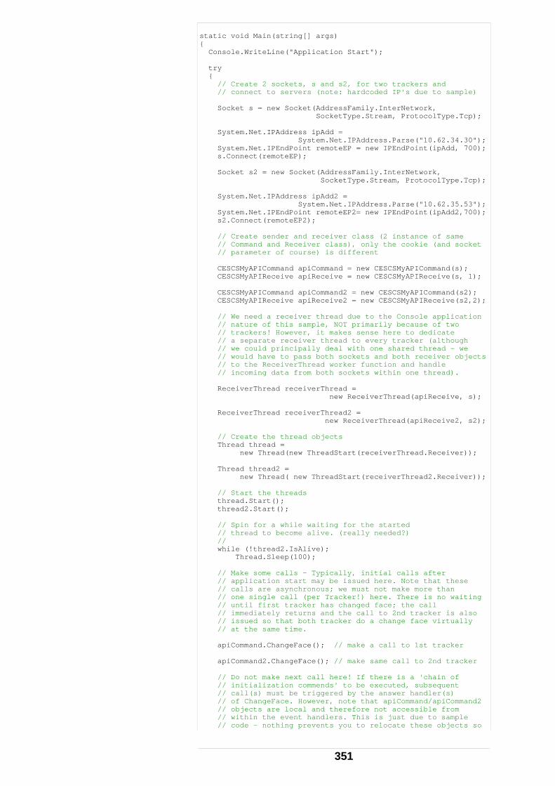
static void Main(string[] args) { Console.WriteLine("Application Start"); try { // Create 2 sockets, s and s2, for two trackers and // connect to servers (note: hardcoded IP's due to sample) Socket s = new Socket(AddressFamily.InterNetwork, SocketType.Stream, ProtocolType.Tcp); System.Net.IPAddress ipAdd = System.Net.IPAddress.Parse("10.62.34.30"); System.Net.IPEndPoint remoteEP = new IPEndPoint(ipAdd, 700); s.Connect(remoteEP); Socket s2 = new Socket(AddressFamily.InterNetwork, SocketType.Stream, ProtocolType.Tcp); System.Net.IPAddress ipAdd2 = System.Net.IPAddress.Parse("10.62.35.53"); System.Net.IPEndPoint remoteEP2= new IPEndPoint(ipAdd2,700); s2.Connect(remoteEP2); // Create sender and receiver class (2 instance of same // Command and Receiver class), only the cookie (and socket // parameter of course) is different CESCSMyAPICommand apiCommand = new CESCSMyAPICommand(s); CESCSMyAPIReceive apiReceive = new CESCSMyAPIReceive(s, 1); CESCSMyAPICommand apiCommand2 = new CESCSMyAPICommand(s2); CESCSMyAPIReceive apiReceive2 = new CESCSMyAPIReceive(s2,2); // We need a receiver thread due to the Console application // nature of this sample, NOT primarily because of two // trackers! However, it makes sense here to dedicate // a separate receiver thread to every tracker (although // we could principally deal with one shared thread - we // would have to pass both sockets and both receiver objects // to the ReceiverThread worker function and handle // incoming data from both sockets within one thread). ReceiverThread receiverThread = new ReceiverThread(apiReceive, s); ReceiverThread receiverThread2 = new ReceiverThread(apiReceive2, s2); // Create the thread objects Thread thread = new Thread(new ThreadStart(receiverThread.Receiver)); Thread thread2 = new Thread( new ThreadStart(receiverThread2.Receiver)); // Start the threads thread.Start(); thread2.Start(); // Spin for a while waiting for the started // thread to become alive. (really needed?) // while (!thread2.IsAlive); Thread.Sleep(100); // Make some calls - Typically, initial calls after // application start may be issued here. Note that these // calls are asynchronous; we must not make more than // one single call (per Tracker!) here. There is no waiting // until first tracker has changed face; the call // immediately returns and the call to 2nd tracker is also // issued so that both tracker do a change face virtually // at the same time. apiCommand.ChangeFace(); // make a call to 1st tracker apiCommand2.ChangeFace(); // make same call to 2nd tracker // Do not make next call here! If there is a 'chain of // initialization commends' to be executed, subsequent // call(s) must be triggered by the answer handler(s) // of ChangeFace. However, note that apiCommand/apiCommand2 // objects are local and therefore not accessible from // within the event handlers. This is just due to sample // code - nothing prevents you to relocate these objects so
351
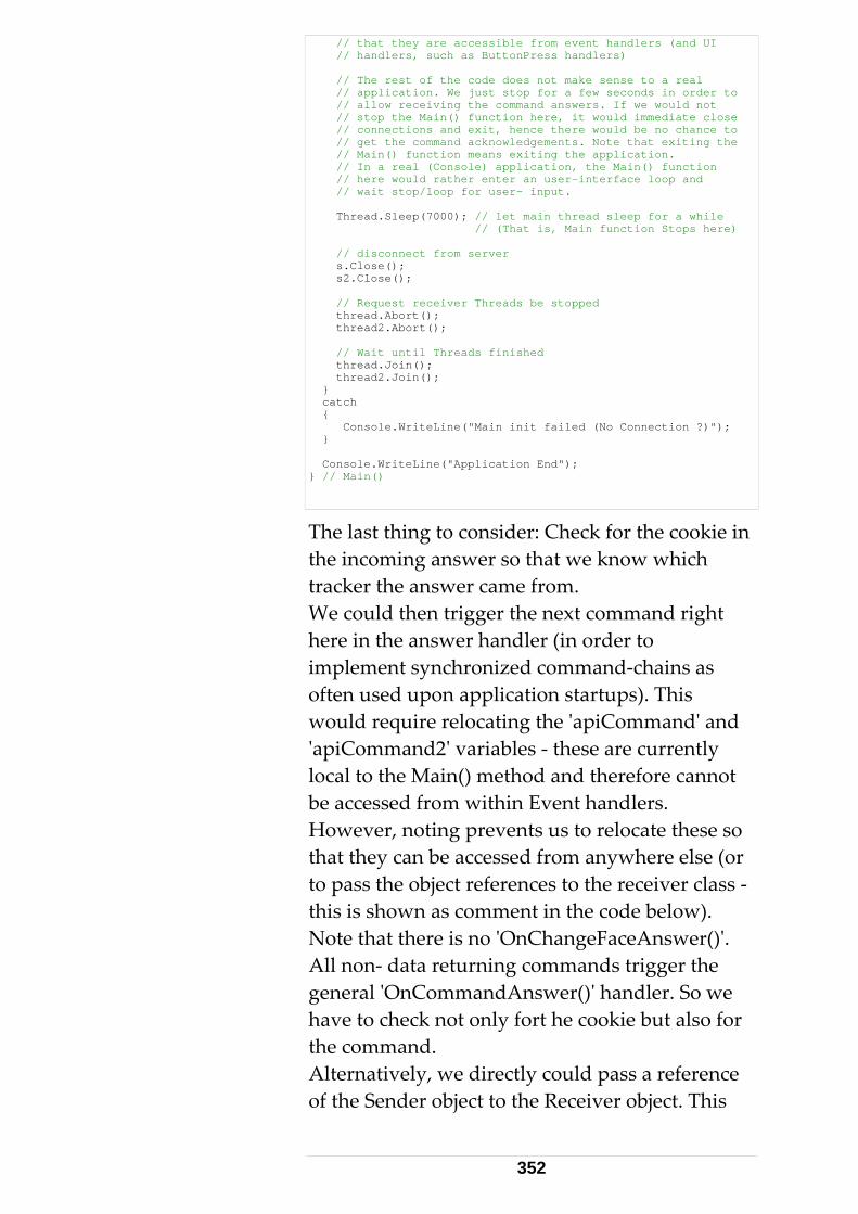
// that they are accessible from event handlers (and UI // handlers, such as ButtonPress handlers) // The rest of the code does not make sense to a real // application. We just stop for a few seconds in order to // allow receiving the command answers. If we would not // stop the Main() function here, it would immediate close // connections and exit, hence there would be no chance to // get the command acknowledgements. Note that exiting the // Main() function means exiting the application. // In a real (Console) application, the Main() function // here would rather enter an user-interface loop and // wait stop/loop for user- input. Thread.Sleep(7000); // let main thread sleep for a while // (That is, Main function Stops here) // disconnect from server s.Close(); s2.Close(); // Request receiver Threads be stopped thread.Abort(); thread2.Abort(); // Wait until Threads finished thread.Join(); thread2.Join(); } catch { Console.WriteLine("Main init failed (No Connection ?)"); } Console.WriteLine("Application End"); } // Main()
The last thing to consider: Check for the cookie in the incoming answer so that we know which tracker the answer came from. We could then trigger the next command right here in the answer handler (in order to implement synchronized command‐chains as often used upon application startups). This would require relocating the ʹapiCommandʹ and ʹapiCommand2ʹ variables ‐ these are currently local to the Main() method and therefore cannot be accessed from within Event handlers. However, noting prevents us to relocate these so that they can be accessed from anywhere else (or to pass the object references to the receiver class ‐ this is shown as comment in the code below). Note that there is no ʹOnChangeFaceAnswer()ʹ. All non‐ data returning commands trigger the general ʹOnCommandAnswer()ʹ handler. So we have to check not only fort he cookie but also for the command. Alternatively, we directly could pass a reference of the Sender object to the Receiver object. This
352
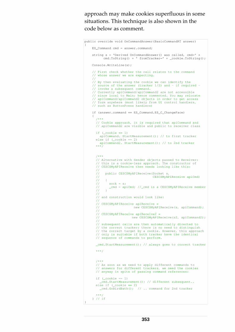
approach may make cookies superfluous in some situations. This technique is also shown in the code below as comment. public override void OnCommandAnswer(BasicCommandRT answer) { ES_Command cmd = answer.command; string s = "Derived OnCommandAnswer() was called, cmd=" + cmd.ToString() + " fromTracker=" + _cookie.ToString(); Console.WriteLine(s); // First check whether the call relates to the command // whose answer we are expecting. // // By then evaluating the cookie we can identify the // source of the answer (tracker 1/2) and - if required - // invoke a subsequent command. // Currently apiCommand/apiCommand2 are not accessible // since local to Main; hence commented. You may relocate // apiCommand/apiCommand2 objects in order to get access // form anywhere (most likely from UI control handlers, // such as ButtonPress handlers) if (answer.command == ES_Command.ES_C_ChangeFace) { /*** // Cookie approach, it is required that apiCommand and // apiCommand2 are visible and public to receiver class if (_cookie == 1) apiCommand. StartMeasurement(); // to first tracker else if (_cookie == 2) apiCommand2. StartMeasurement(); // to 2nd tracker ***/ /*** // Alternative with Sender objects passed to Receiver: // this is a cookie-less approach. The constructor of // CESCSMyAPIReceive then needs looking like this: // // public CESCSMyAPIReceive(Socket s, // CESCSMyAPIReceive apiCmd) // { // sock = s; // _cmd = apiCmd; //_cmd is a CESCSMyAPIReceive member // } // // and construction would look like: // // CESCSMyAPIReceive apiReceive = // new CESCSMyAPIReceive(s, apiCommand); // // CESCSMyAPIReceive apiReceive2 = // new CESCSMyAPIReceive(s2, apiCommand2); // // subsequent calls are then automatically directed to // the correct tracker; there is no need to distinguish // the correct target by a cookie. However, this approach // only is suitable if both tracker have the identical // sequence of commands to perform. _cmd.StartMeasurement(); // always goes to correct tracker ***/ /*** // As soon as we need to apply different commands to // answers for different trackers, we need the cookies // anyway in spite of passing command references: if (_cookie == 1) _cmd.StartMeasurement(); // different subsequent.. else if (_cookie == 2) _cmd.GoBirdBath(); // .. command for 2nd tracker ***/ } // if }
353
7 Base User Interface (BUI)
7.1 Client Programming and BUI 7.1.1 Measurement BUI versus Compensation Applications The emScon software comes with several graphical User‐ Interfaces represented by a WEB‐ application (running on internet explorer). It is important to distinguish between standalone applications and integrated applications. The Compensation‐, Field Check‐ and Tracker Server modules are pure ‘stand‐ alone’ applications. For details see the designated special manuals fore these applications. On the other hand, the so‐called Measurement‐‘Base User Interface’ (BUI) does not make sense to be used as a stand‐ alone application, except for system testing reasons. This chapter exclusively addresses the Measurement‐ BUI. The BUI requires a Master‐ application the BUI is hosted by. It mainly acts as a ‘Display’ component of such a host application. There is also a Toolbar to control the most common Tracker actions. However, there is (other than in the stand‐alone WEB applications) no way to perform settings such as ‘Units’, CS‐ Type, Filters etc. These have to be performed by the Master application the BUI is hosted by.
354
7.1.2 EmScon Basic User Interface (BUI) The emScon Base User Interface (emScon BUI) provides a graphical interface to emSconʹs most common functions. Access to it is provided through the Microsoft Internet Explorer.
The BUI includes:
• A Toolbar for common sensor control such as sensor moving or triggering measurements.
• A window for result display (DRO).
• Web pages providing access to selected sensor and system settings.
7.1.3 Integration of BUI into applications The BUI can be used as standalone application for testing reasons. However, there is no real practical use for the BUI as a standalone application. The BUI, however, allows to be integrated to client applications. This approach is demonstrated in Sample 13.
The BUI provides a graphical interface to emScon. However, general system settings, such as Units, CS‐type etc. are not provided by the BUI. An application hosting the BUI will have to do emScon settings control through the ordinary TPI interface. Also retrieving measurement data has to be provided through the TPI (Unless one wants just to VIEW the data through the DRO). The BUI can be launched from within an application (see Sample 13), if not already running. However, it is also possible to start the BUI manually and execute a ʹdata‐ catcherʹ application (without BUI launch) after that. Such an application then is capable to process data (triggered by the BUI) as far as appropriate handlers are provided.
355
7.1.4 Sample 13 This sample is a ʹBUI‐ launcher and ‐ listenerʹ, to launch the emScon BUI from within a client application. That is, the BUI becomes part of the client application. The client application (= BUI host) is mainly used to ʹcatchʹ measurements triggered by the BUI in order to do further data processing. The application shows how to perform initial settings (that cannot be set with the BUI) and how to catch the measurements (triggered from the BUI). These measurement‐ results are just written to the applications dialog (which does not really make sense because they are already displayed on the BUI Page. A real application would do further processing, such as storing the measurements into a database etc.) The sample is in Visual Basic. However, the principles would not change for a C++ application.
Further details see ʹReadme.txtʹ file and code‐ comments in ʹBUILaunch.frmʹ source‐ file in Sample13 Folder.
Also refer to BUI documentation (User Manual) for details.
Hint: Even if you are not interested in a ʹBUI‐ controlledʹ application, this sample may still be useful to demonstrate the handling of continuous measurements on using the COM (LTControl) interface. That is, if writing emScon application with VisualBasic or VBA (Excel etc.). At the very end of the file ʹBUILaunch.frmʹ, you can find an event‐ handler function that demonstrates on how to receive continuous measurements through the emScon COM interface.
356
8 Selected Commands in Detail
8.1 Special Functions Some of the more complex commands/procedures, which have been referred to in this manual are described in detail, with some background information. 8.1.1 Get Reflectors Command The GetReflectors command is often misinterpreted. GetReflectors is used to ʹaskʹ the Tracker Server, which reflectors are currently defined, and to get the relation between reflector names and reflector IDs.
Related Commands
• SetReflector
• GetReflector
357
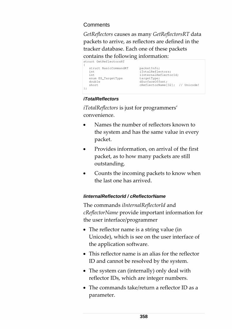
Comments
GetReflectors causes as many GetReflectorsRT data packets to arrive, as reflectors are defined in the tracker database. Each one of these packets contains the following information: struct GetReflectorsRT { struct BasicCommandRT packetInfo; int iTotalReflectors; int iInternalReflectorId; enum ES_TargetType targetType; double dSurfaceOffset; short cReflectorName[32]; // Unicode! };
iTotalReflectors
iTotalReflectors is just for programmers’ convenience.
• Names the number of reflectors known to the system and has the same value in every packet.
• Provides information, on arrival of the first packet, as to how many packets are still outstanding.
• Counts the incoming packets to know when the last one has arrived.
IinternalReflectorId / cReflectorName
The commands iInternalReflectorId and cReflectorName provide important information for the user interface/programmer
• The reflector name is a string value (in Unicode), which is see on the user interface of the application software.
• This reflector name is an alias for the reflector ID and cannot be resolved by the system.
• The system can (internally) only deal with reflector IDs, which are integer numbers.
• The commands take/return a reflector ID as a parameter.
358
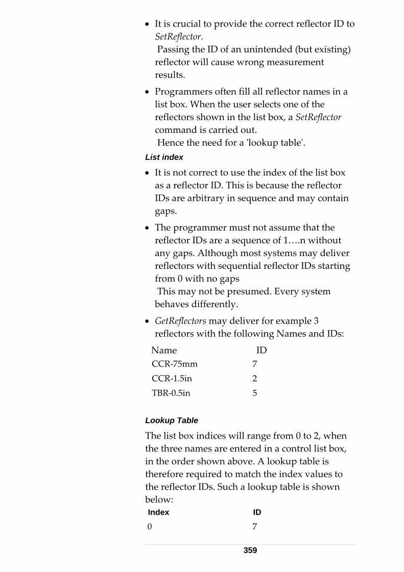
• It is crucial to provide the correct reflector ID to SetReflector. Passing the ID of an unintended (but existing) reflector will cause wrong measurement results.
• Programmers often fill all reflector names in a list box. When the user selects one of the reflectors shown in the list box, a SetReflector command is carried out. Hence the need for a ʹlookup tableʹ.
List index
• It is not correct to use the index of the list box as a reflector ID. This is because the reflector IDs are arbitrary in sequence and may contain gaps.
• The programmer must not assume that the reflector IDs are a sequence of 1….n without any gaps. Although most systems may deliver reflectors with sequential reflector IDs starting from 0 with no gaps This may not be presumed. Every system behaves differently.
• GetReflectors may deliver for example 3 reflectors with the following Names and IDs:
Name ID CCR‐75mm 7 CCR‐1.5in 2 TBR‐0.5in 5
Lookup Table
The list box indices will range from 0 to 2, when the three names are entered in a control list box, in the order shown above. A lookup table is therefore required to match the index values to the reflector IDs. Such a lookup table is shown below: Index ID
0 7
359
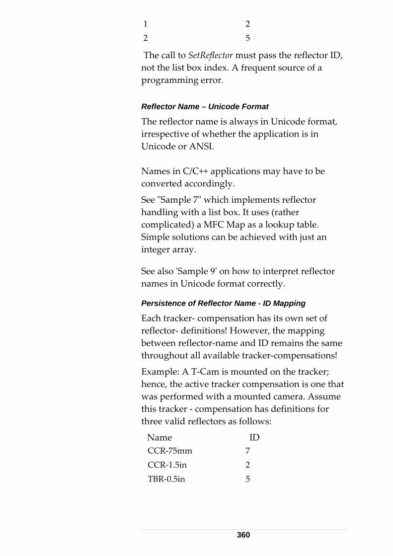
1 2 2 5
The call to SetReflector must pass the reflector ID, not the list box index. A frequent source of a programming error. Reflector Name – Unicode Format
The reflector name is always in Unicode format, irrespective of whether the application is in Unicode or ANSI. Names in C/C++ applications may have to be converted accordingly.
See ʺSample 7ʺ which implements reflector handling with a list box. It uses (rather complicated) a MFC Map as a lookup table. Simple solutions can be achieved with just an integer array.
See also ʹSample 9ʹ on how to interpret reflector names in Unicode format correctly.
Persistence of Reflector Name - ID Mapping
Each tracker‐ compensation has its own set of reflector‐ definitions! However, the mapping between reflector‐name and ID remains the same throughout all available tracker‐compensations!
Example: A T‐Cam is mounted on the tracker; hence, the active tracker compensation is one that was performed with a mounted camera. Assume this tracker ‐ compensation has definitions for three valid reflectors as follows:
Name ID CCR‐75mm 7 CCR‐1.5in 2 TBR‐0.5in 5
360
Now, the T‐Cam is removed, and hence another tracker‐ compensation becomes active (one that was performed without a mounted T‐Cam). Letʹs assume that this compensation has only two reflector definitions: CCR‐1.5in and TBR‐0.5in. Conveniently, the mapping between name and ID remained the same as it was in the previous compensation:
Name ID CCR‐1.5in 2 TBR‐0.5in 5
If reflector ID 7 was the active one at the time the camera was removed, you will now get a ʹwrong current reflectorʹ error message on executing reflector‐ dependent commands. Thus, the application must first set one of the now available IDs 2 or 3 with the ʹSetReflectorʹ command.
The fact that the relation between reflector ID and Name remains the same throughout all tracker‐ compensations may be convenient to application programmers since there is no need to re‐query all reflector mappings upon a tracker compensation change. 8.1.2 Still Image Command For trackers equipped with an Overview Camera, the GetStillImage command takes an image and delivers it as a file image data block. Related Commands
• GetStillImage
• SetCameraParams
• GetCameraParams
• StillImageGetFile (COM, not in C++)
• WriteDiskFile (COM only)
361
These commands are available on all TPI levels (C, C++, COM). Set/GetCameraParameters is not explained here further.
Preconditions
The following preconditions have to be fulfilled:
• Camera mounted on tracker
• System settings: “Has video” flag activated
• Tracker must be in camera view (command ActivateCameraView)
Application of GetStillImage – C/C++
The application of GetStillImage is explained below using code fragments.
GetStillImage must be called with the parameter ES_SI_Bitmap. The parameter ES_SI_Jpeg is not supported yet.
• The answer to a successfully executed GetStillImage command results in a GetStillImageRT data structure.
• Apart from the common header information, this structure echoes the file type (imageFiletype =ES_SI_Bitmap), the size of the file (lFileSize), and the first Byte of the file (cFileStart).
• The following code accesses the core file data and writes it to a physical disk file:
362
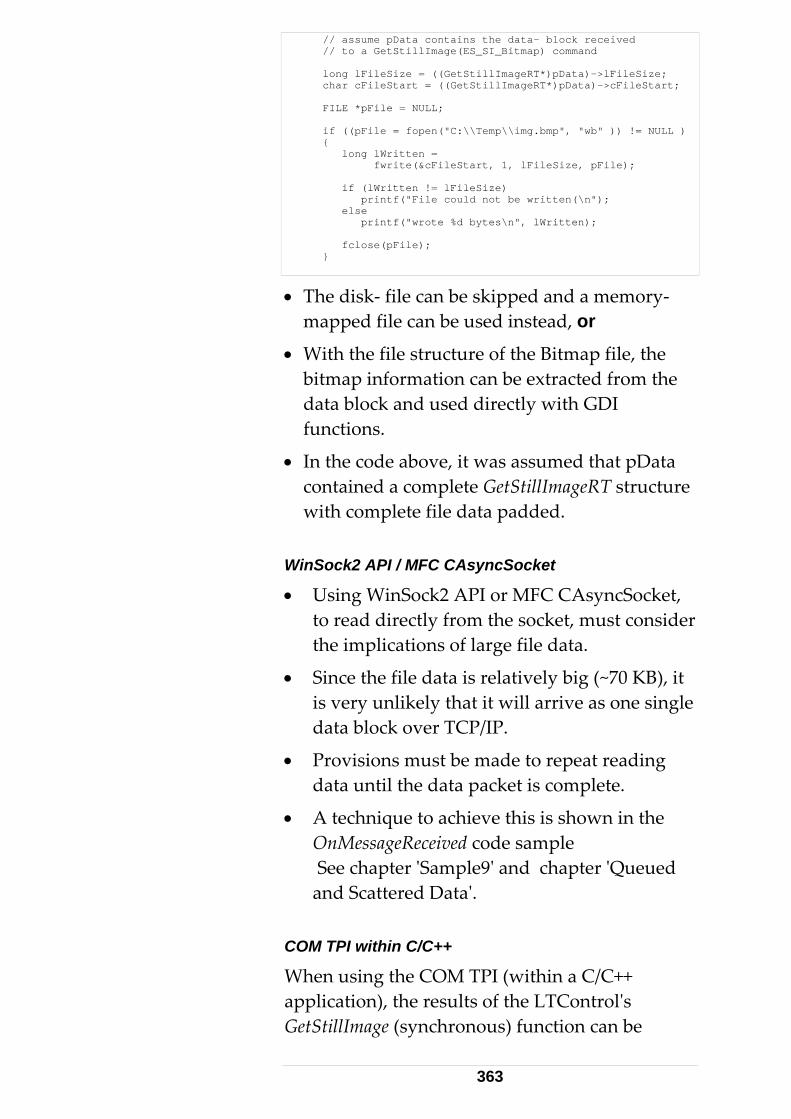
// assume pData contains the data- block received // to a GetStillImage(ES_SI_Bitmap) command long lFileSize = ((GetStillImageRT*)pData)->lFileSize; char cFileStart = ((GetStillImageRT*)pData)->cFileStart; FILE *pFile = NULL; if ((pFile = fopen("C:\\Temp\\img.bmp", "wb" )) != NULL ) { long lWritten = fwrite(&cFileStart, 1, lFileSize, pFile); if (lWritten != lFileSize) printf("File could not be written(\n"); else printf("wrote %d bytes\n", lWritten); fclose(pFile); }
• The disk‐ file can be skipped and a memory‐mapped file can be used instead, or
• With the file structure of the Bitmap file, the bitmap information can be extracted from the data block and used directly with GDI functions.
• In the code above, it was assumed that pData contained a complete GetStillImageRT structure with complete file data padded.
WinSock2 API / MFC CAsyncSocket
• Using WinSock2 API or MFC CAsyncSocket, to read directly from the socket, must consider the implications of large file data.
• Since the file data is relatively big (~70 KB), it is very unlikely that it will arrive as one single data block over TCP/IP.
• Provisions must be made to repeat reading data until the data packet is complete.
• A technique to achieve this is shown in the OnMessageReceived code sample See chapter ʹSample9ʹ and chapter ʹQueued and Scattered Dataʹ.
COM TPI within C/C++
When using the COM TPI (within a C/C++ application), the results of the LTControlʹs GetStillImage (synchronous) function can be
363
assumed to be complete. See related code extract below. When receiving StillImage data asynchronously (Event Handler, MessageHandler), the difference is that the data will not be provided directly through a parameter. So ILTConnect::GetData() must be used first.
Note the Variant‐ type parameter of the fileData.
364
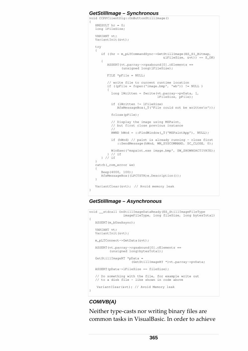
GetStillImage – Synchronous void CCPPClientDlg::OnButtonStillImage() { HRESULT hr = 0; long lFileSize; VARIANT vt; VariantInit(&vt); try { if ((hr = m_pLTCommandSync->GetStillImage(ES_SI_Bitmap, &lFileSize, &vt)) == S_OK) { ASSERT(vt.parray->rgsabound[0].cElements == (unsigned long)lFileSize); FILE *pFile = NULL; // write file to current runtime location if ((pFile = fopen("image.bmp", "wb")) != NULL ) { long lWritten = fwrite(vt.parray->pvData, 1, lFileSize, pFile); if (lWritten != lFileSize) AfxMessageBox(_T("File could not be written\n")); fclose(pFile); // Display the image using MSPaint, // but first close previous instance // HWND hWnd = ::FindWindow(_T("MSPaintApp"), NULL); if (hWnd) // paint is already running - close first ::SendMessage(hWnd, WM_SYSCOMMAND, SC_CLOSE, 0); WinExec("mspaint.exe image.bmp", SW_SHOWNOACTIVATE); } // if } // if } catch(_com_error &e) { Beep(4000, 100); AfxMessageBox((LPCTSTR)e.Description()); } VariantClear(&vt); // Avoid memory leak }
GetStillImage – Asynchronous void __stdcall OnStillImageDataReady(ES_StillImageFileType imageFileType, long fileSize, long bytesTotal) { ASSERT(m_bUseAsync); VARIANT vt; VariantInit(&vt); m_pLTConnect->GetData(&vt); ASSERT(vt.parray->rgsabound[0].cElements == (unsigned long)bytesTotal); GetStillImageRT *pData = (GetStillImageRT *)vt.parray->pvData; ASSERT(pData->lFileSize == fileSize); // Do something with the file, for example write out // to a disk file – like shown in code above VariantClear(&vt); // Avoid Memory leak }
COM/VB(A)
Neither type‐casts nor writing binary files are common tasks in VisualBasic. In order to achieve
365
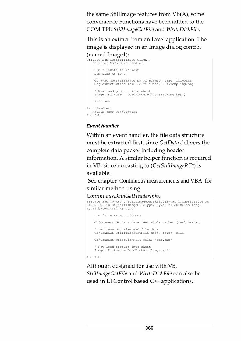
the same StillImage features from VB(A), some convenience Functions have been added to the COM TPI: StillImageGetFile and WriteDiskFile.
This is an extract from an Excel application. The image is displayed in an Image dialog control (named Image1): Private Sub GetStillImage_Click() On Error GoTo ErrorHandler Dim fileData As Variant Dim size As Long ObjSync.GetStillImage ES_SI_Bitmap, size, fileData ObjConnect.WriteDiskFile fileData, "C:\Temp\img.bmp" ' Now load picture into sheet Image1.Picture = LoadPicture("C:\Temp\img.bmp") Exit Sub ErrorHandler: MsgBox (Err.Description) End Sub
Event handler
Within an event handler, the file data structure must be extracted first, since GetData delivers the complete data packet including header information. A similar helper function is required in VB, since no casting to (GetStillImageRT*) is available. See chapter ʹContinuous measurements and VBAʹ for similar method using ContinuousDataGetHeaderInfo. Private Sub ObjAsync_StillImageDataReady(ByVal imageFileType As LTCONTROLLib.ES_StillImageFileType, ByVal fileSize As Long, ByVal bytesTotal As Long) Dim fsize as Long ‘dummy ObjConnect.GetData data 'Get whole packet (incl header) ' retrieve out size and file data ObjConnect.StillImageGetFile data, fsize, file ObjConnect.WriteDiskFile file, "img.bmp" ' Now load picture into sheet Image1.Picture = LoadPicture("img.bmp") End Sub
Although designed for use with VB, StillImageGetFile and WriteDiskFile can also be used in LTControl based C++ applications.
366
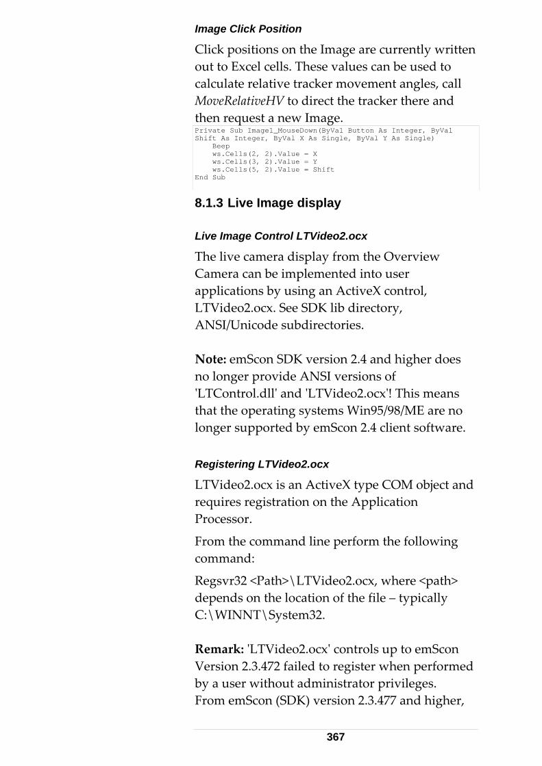
Image Click Position
Click positions on the Image are currently written out to Excel cells. These values can be used to calculate relative tracker movement angles, call MoveRelativeHV to direct the tracker there and then request a new Image. Private Sub Image1_MouseDown(ByVal Button As Integer, ByVal Shift As Integer, ByVal X As Single, ByVal Y As Single) Beep ws.Cells(2, 2).Value = X ws.Cells(3, 2).Value = Y ws.Cells(5, 2).Value = Shift End Sub
8.1.3 Live Image display Live Image Control LTVideo2.ocx
The live camera display from the Overview Camera can be implemented into user applications by using an ActiveX control, LTVideo2.ocx. See SDK lib directory, ANSI/Unicode subdirectories. Note: emScon SDK version 2.4 and higher does no longer provide ANSI versions of ʹLTControl.dllʹ and ʹLTVideo2.ocxʹ! This means that the operating systems Win95/98/ME are no longer supported by emScon 2.4 client software. Registering LTVideo2.ocx
LTVideo2.ocx is an ActiveX type COM object and requires registration on the Application Processor.
From the command line perform the following command:
Regsvr32 <Path>\LTVideo2.ocx, where <path> depends on the location of the file – typically C:\WINNT\System32. Remark: ʹLTVideo2.ocxʹ controls up to emScon Version 2.3.472 failed to register when performed by a user without administrator privileges. From emScon (SDK) version 2.3.477 and higher,
367
restricted users also may register these components. However, be aware that only the ʹownerʹ may then use it. Whenever possible, it is recommended to have LTVideo2.ocx registered by an administrator so that all users may use them without any additional measures. Limitations: As mentioned, the controls ʹLTControl.dllʹ and ʹLTVideo2.ocxʹ do no longer require administrator privileges for registering (From SDK V 2.4.x). However, developing applications as restricted users may cause certain problems when using older development tools (Which is a limitation of these tools, not a limitation of emScon components). For example Visual Basic V6 (and maybe also Office V6‐ built‐in VBA) is likely to cause problems when referencing COM objects. (VB 6 for example tries to write temporary files to the location of registered components, which often fails for restricted users). Hence we have to recommend being administrator while developing emScon applications. This does not apply to the users of those applications, i.e. once finished developing, they will also run for restricted users. On the other hand, most recent development environments, such as VB.NET (2003 and up) and Office XP should not cause any problems for restricted users, even not for development tasks. Moreover, we considered major problems on using Windows XP SP1 in combination with restricted users and registration issues. We highly recommend using Win XP SP2 or Win 2K. ANSI/Unicode Version
Use the Unicode version for WinNT/2000/XP.
368
See Version info of LTVideo2.ocx for details, under File Properties > Version TAB. Note: emScon SDK version 2.4 and higher does no longer provide ANSI versions of ʹLTControl.dllʹ and ʹLTVideo2.ocxʹ! This means that the operating systems Win95/98/ME are no longer supported by emScon 2.4 client software. Development Platforms
For Visual Basic or Office, the ActiveX controls must be added as a reference.
For VC++, a wrapper class is generated using:
Add to Project/Components > Controls > Controls type library from Visual Studio. LTVideo2.tlb
LTVideo2.tlb is the related type library delivered for convenience. LTVideo2.ocx contains all type information required. Server Address
LTVideo2.ocx has a property server address, which must be set according to your server address.
The port number is 5001. Any changes to the port number must also be done on the server side.
The size must have a width/height proportion of 4:3. The image must be started/stopped by invoking the method Start/StopLiveImage.
See Microsoft documentation, for further information on how to use ActiveX controls in general. Events/Methods
The essential methods of the camera OCX are:
• StartLiveImage()
369
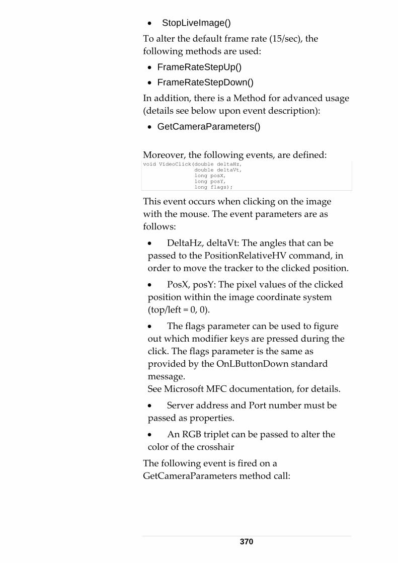
• StopLiveImage()
To alter the default frame rate (15/sec), the following methods are used:
• FrameRateStepUp() • FrameRateStepDown()
In addition, there is a Method for advanced usage (details see below upon event description):
• GetCameraParameters()
Moreover, the following events, are defined: void VideoClick(double deltaHz, double deltaVt, long posX, long posY, long flags);
This event occurs when clicking on the image with the mouse. The event parameters are as follows:
• DeltaHz, deltaVt: The angles that can be passed to the PositionRelativeHV command, in order to move the tracker to the clicked position.
• PosX, posY: The pixel values of the clicked position within the image coordinate system (top/left = 0, 0).
• The flags parameter can be used to figure out which modifier keys are pressed during the click. The flags parameter is the same as provided by the OnLButtonDown standard message. See Microsoft MFC documentation, for details.
• Server address and Port number must be passed as properties.
• An RGB triplet can be passed to alter the color of the crosshair
The following event is fired on a GetCameraParameters method call:
370
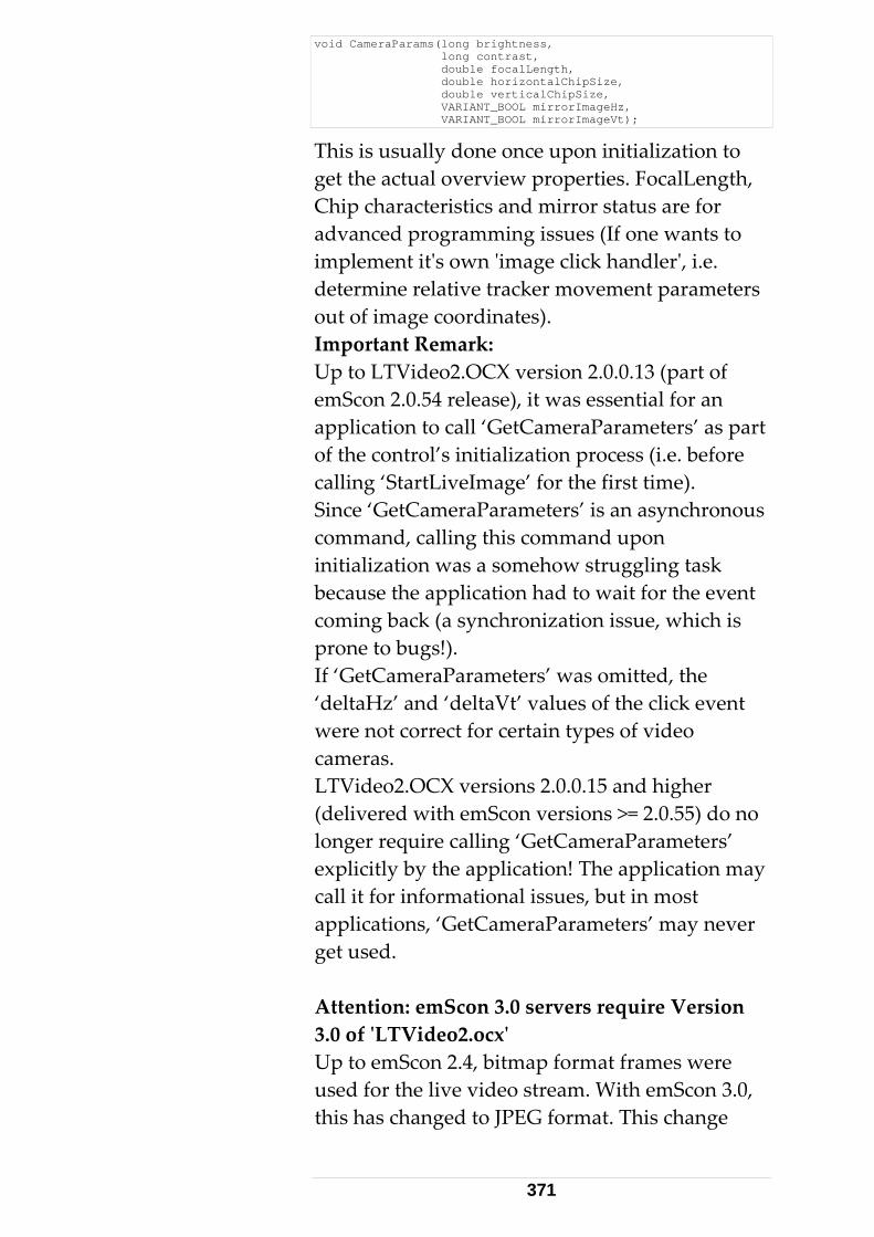
void CameraParams(long brightness, long contrast, double focalLength, double horizontalChipSize, double verticalChipSize, VARIANT_BOOL mirrorImageHz, VARIANT_BOOL mirrorImageVt);
This is usually done once upon initialization to get the actual overview properties. FocalLength, Chip characteristics and mirror status are for advanced programming issues (If one wants to implement itʹs own ʹimage click handlerʹ, i.e. determine relative tracker movement parameters out of image coordinates). Important Remark: Up to LTVideo2.OCX version 2.0.0.13 (part of emScon 2.0.54 release), it was essential for an application to call ‘GetCameraParameters’ as part of the control’s initialization process (i.e. before calling ‘StartLiveImage’ for the first time). Since ‘GetCameraParameters’ is an asynchronous command, calling this command upon initialization was a somehow struggling task because the application had to wait for the event coming back (a synchronization issue, which is prone to bugs!). If ‘GetCameraParameters’ was omitted, the ‘deltaHz’ and ‘deltaVt’ values of the click event were not correct for certain types of video cameras. LTVideo2.OCX versions 2.0.0.15 and higher (delivered with emScon versions >= 2.0.55) do no longer require calling ‘GetCameraParameters’ explicitly by the application! The application may call it for informational issues, but in most applications, ‘GetCameraParameters’ may never get used. Attention: emScon 3.0 servers require Version 3.0 of ʹLTVideo2.ocxʹ Up to emScon 2.4, bitmap format frames were used for the live video stream. With emScon 3.0, this has changed to JPEG format. This change
371
requires using ʹLTVideo2.ocxʹ Version 3.0.x (or higher). This new version of the control (it comes with SDK 3.0) is backward compatible to earlier emScon server versions. That means, it is able to handle JPEG as well as BITMAP formatted video frames and will therefore also work with older emScon servers. Old versions of ʹLTVideo2.ocxʹ, however, will not be able to display live videos of emScon 3.0 servers. Sample 18
This Visual Basic sample demonstrates how to implement a Live Video image based on the ʹLTVideo2.ocxʹ ActiveX component.
Note that ʹLTVideo2.ocxʹ (part of the emScon SDK) must be registered first.
If no Visual Basic development environment is available, the code can easily be ported to VBA (Excel, or any other MS Office application with VBA support). Sample 18 demonstrates the full functionality of the control, including GetCameraParameters events and ʹClick‐ handlerʹ. The code is simple enough to be self‐ explaining. Further details see ʹReadme.txtʹ file in Sample18 folder and code‐ comments in source files. Attention: emScon 3.0 servers require version 3.0 of the ʹLTVideo2.ocxʹ. This version of the control is also compatible to older emScon servers. Sample 19
This C++ (MFC) sample demonstrates how to implement a Live Video image without using the ʹLTVideo2.ocxʹ. It is rather based on emScons native video API. Nevertheless, we do not recommended using
372
this approach for Windows‐ platform targeted applications!
For Windows based applications, we highly recommend rather using the ʹready to useʹ ʹLTVideo2.ocxʹ control. ʹLTVideo2.ocxʹ is part of the SDK and its usage is demonstrated in Sample 18.
However, the current LiveVideo CPP application might be useful for non‐ Windows based applications (e.g. Linux) since support for LTVideo2.ocx will not be available there.
In this sample, the application directly connects to the Video Port (# 5001) of the emScon server. The command interface is based on Ansi text tokens. The following commands are supported: ʺLiveImageStartʺ
ʺLiveImageStopʺ
ʺFrameRateStepUpʺ
ʺFrameRateStepDownʺ
ʺRequestCameraParametersʺ These tokens can be sent directly to an open socket connection to port 5001. Arrival Data includes the following types:
‐ Live Image Data Blocks (Bitmap format)
Note that each image arrives in two chunks and must be composed to a complete image before displaying it.
‐ Camera Parameter Block Result of a ʹRequestCameraParametersʹ call. See source code, function OnReceive(), on how to parse incoming data. See source code, function OnPaint(), on how to display image data.
373
The source code is commented in detail and should be self‐ explaining. However, as already mentioned, using the LiveVideo TCP/IP interface directly, as shown in this sample only is recommended for non Windows client platforms. Rather base clients on ʹLTVideo2.ocxʹ for Windows platform targeted application. Further details see ʹReadme.txtʹ file in Sample19 folder and code‐ comments in source files.
Attention: New Live Image Format with emScon 3.0 !
Up to emScon 2.4, bitmap format frames were used for the live video stream. With emScon 3.0, this has changed to JPEG format. Sample 19 thus has undergone an extension since emScon 2.4 SDK was released; it supports now both, Bitmap and Jpeg formats. Support of bitmaps is only left for backward compatibility to former emScon servers. For Jpeg image conversion and display, a public‐domain Third‐Party library has been used (CxImage by Davide Pizzolato). The emScon 3.0 SDK just contains a few parts of the CxImage framework (some include‐ files and two libraries for static linking ‐ i.e. only those parts as far as needed to build our sample). If interested, you may get the complete CxImage source from the internet.
8.1.4 Orient To Gravity Procedure This function is used to measure the tilt of the trackerʹs primary z‐axis (standing axis) with respect to the vertical. This can be used to orient the measurement network to gravity. The tilt is specified by two angular components about the trackerʹs internal x and y‐axes.
374
Related Command
• CallOrientToGravity
Comments
• This command is only available in combination with a Leica ʹNivelʹ inclination Sensor.
• Executing this command drives the tracker head to 4 different positions on the xy plane:
1. Taking ʹNivelʹ measurement samples.
2. In addition, the station inclination parameters Ix and Iy are calculated and returned as result parameters.
• Executing this command does not ʹimplicitlyʹ apply any orientation values to the system.
• In order to ʹactivateʹ the station orientation to gravity, the two result values, Ix and Iy, must be explicitly set with the command SetStationOrientationParams (Rotation angles rot1 and rot2). See Section 9.2 for mathematical description.
8.1.5 Transformation Procedure See Section 9.2 for a detailed discussion of the Transformation issue. This procedure matches a measured set of points to a given set of nominal points by using a least squares, best fit method. The procedure calculates the 7 parameters (x,y,z, omega, phi, kappa, scale), which describe the ʹtransformation filterʹ to be applied to the measured points in order to represent these in the coordinate system defined by the nominal points.
375
Related Commands
• ClearTransformationNominalPointList
• ClearTransformationActualPointList
• AddTransformationNominalPoint
• AddTransformationActualPoint
• SetTransformationInputParams
• GetTransformationInputParams
• CallTransformation
• GetTransformedPoints
Comments
The command CallTransformation delivers a set of parameters that can then be applied as a measurement ʹconversion filterʹ to the emScon server by using the command SetTransformationParams. In other words: CallTransformation is just a mathematical routine for providing these values; there is no effect to the measurements delivered by the emScon per se. Only after applying these values to the system in a second step (through using SetTransformationParams), they start acting as a filter. Note that you also may get the input values for SetTransformationParams from a different source (e.g. your own transformation routine or by some nominal design). Therefore, CallTransformation is only a utility routine provided by the emScon server. In contrast to SetTransformationParams, it does not belong to the core‐functionality of the system for performing measurements.
Before doing a CallTransformation, both point lists, Nominal and Actual must be prepared by using the ʹAdd…ʹ commands (use ʹClear…ʹ commands prior to setup a new list, since existing lists remain persistent). Both lists must contain the same number of elements in matching order.
376
The system settings of emScon (units, coordinate type and coordinate system) must reflect the current input data. Point input values (nominal/actual) are interpreted by emScon based on the current emScon system settings.
• Additional (optional) parameters can be set by using the SetTransformationInputParams command (Mainly used to fix certain result parameters, for example if scale shall be fixed to exactly 1.0). By default, i.e. if no call to SetTransformationInputParams was ever made, all result parameters are assumed as ʹUnknownʹ (not fixed). That means that all 7 parameters to be determined are given a low StdDev of 1e+35, which means a low weight and therefore means no constraint). However, since these Parameters ‐ once explicitly set by using SetTransformationInputParams ‐ remain persistent, it is highly recommend always to call this command prior to a transformation calculation. Passing values (0, 0, 0, 0, 0, 0, 1) all with StdDev 1e+35 in practice means to ʹclearʹ all the input parameter‐ constraints (i.e. reset to default). Example: The following call SetTransformationInputParams( ES_TR_AsTransformation, 0.0, 3.0, 0.0, 0.0, 0.0, 0.0, 1.0, 1e+35, 0.0, 1e+35, 1e+35, 1e+35, 1e+35, 0.0) causes to fix the Y‐Coordinate to 3.0 (i.e. a known, fixed value by design) and the Scale to 1.0 since these parameters are specified with low StdDev 0.0 (high weight). All the other parameters theoretically can be given any value (not necessarily 0.0) since their weight is low. It is nevertheless recommended to pass 0.0
377
for ʹfreeʹ result parameters. When using the COM TPI, you may use predefined symbols ʹES_UnknownStdDevʹ, ʹES_FixedStdDevʹ for 1e+35 and 0.0 respectively. Note that any intermediate value can also be used for weighting. (Not only ʹfixʹ and ʹfreeʹ). In case of a value is known approximately, it is suggested to use 1.0e+15 (ES_ApproxStdDev). For further details ‐ especially the meaning of ʹresultTypeʹ (ES_TransResultType) ‐ see section 9.2
• After a successful calculation, additional results in terms of transformed points and residuals can be retrieved optionally by using GetTransformedPoints. Again: None of the 7 calculated transformation parameters (received as output from CallTransformation) are automatically applied to the system. This must be done explicitly by calling SetTransformationParams. See Section 9.2 for mathematical description.
8.1.6 Automated Intermediate Compensation The Intermediate Compensation is a simple and fast procedure to perform a fully automated intermediate compensation, where the tracker is in a fixed installation. Tracker Geometry
Out of a total of 15 parameters, which affect the trueness of the tracker geometry, the most significant changes are affected by these three parameters:
See emScon manuals, for more information.
• Transit axis tilt, i
• Mirror tilt, c
• Vertical index error, j
378
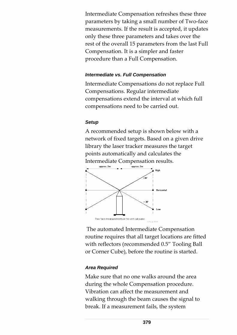
Intermediate Compensation refreshes these three parameters by taking a small number of Two‐face measurements. If the result is accepted, it updates only these three parameters and takes over the rest of the overall 15 parameters from the last Full Compensation. It is a simpler and faster procedure than a Full Compensation. Intermediate vs. Full Compensation
Intermediate Compensations do not replace Full Compensations. Regular intermediate compensations extend the interval at which full compensations need to be carried out. Setup
A recommended setup is shown below with a network of fixed targets. Based on a given drive library the laser tracker measures the target points automatically and calculates the Intermediate Compensation results.
The automated Intermediate Compensation routine requires that all target locations are fitted with reflectors (recommended 0.5” Tooling Ball or Corner Cube), before the routine is started. Area Required
Make sure that no one walks around the area during the whole Compensation procedure. Vibration can affect the measurement and walking through the beam causes the signal to break. If a measurement fails, the system
379
automatically repeats the measurement to achieve a successful measurement, a maximum of three times. Procedure
Requirements
The automated Intermediate Compensation can only be started when the Leica Tracker system is ready to measure.
For the initial setup it is required that the locations of the fixed targets are measured manually. These locations provide the information for the driver points.
• Six Two Face measurements, in two groups of 3 each.
• Each group of 3 points is in an approximate vertical line.
• Minimum distance from the tracker is 2m.
• The high and low measurements should be more than 30 degrees from the horizontal.
• The groups should have a horizontal angle separation of about 180 degrees, i.e. all measurements should lie approximately in the same vertical plane.
Minimum Measurements
A minimum of 4 measurements is required (mathematically). More measurements reduce the influence of errors. In addition, unstable conditions, such as vibrations and rapid temperature changes, make it necessary for more measurements to be taken. The following combinations are examples:
• Eight measurements in 4 pairs (high and low) separated by approx. 90 degrees.
• Twelve measurements in 4 groups of 3 each (high, low, horizontal), separated by
380
approx. 90 degrees.
Related Commands
- ClearDrivePointList
- AddDrivePoint
- CallIntermediateCompensation
- SetCompensation
Comments
Settings
Current emScon system settings, such as units, coordinate system and coordinate type, are taken over when emScon interprets point input (driver point) values. All points in the drive library must be known within ± 2mm (0.0787 in) tolerance, otherwise this will cause an error in the measurements.
The settings, such as units, coordinate system and coordinate system type, must correspond to the input data. Ensure that the settings describe the environment of the driver points before they are uploaded to the server.
One of the first actions of the automated compensation algorithm is to check the geometry of the used driver points. If the target setup fits the requirements (as described above), then the process continues with the measurements, otherwise it will abort.
Compensation Results
A successful Intermediate Compensation procedure returns the following information:
• Total RMS
• Max. Deviation
381
• Error bit filed with the information of warnings and errors.
Compensation Intervals
An intermediate compensation is recommended when the maximum deviation is ≤ 0.0012 deg (13cc). With the command ʹSetCompensationʹ, the newly calculated compensation can be activated by passing a zero parameter: SetCompensation(0).
See detailed description of ʹES_C_SetCompensationʹ (enum ES_C_Command) about the meaning of paramter zero. 8.1.7 Two Face Field-Check A field check is a control process of the Compensation parameters. It checks the condition of the Leica Tracker, with respect to predefined parameters. It does not, however, provide for compensatory corrections. Periodicity
If the tracker is used in a stationary position, conduct the field check on a weekly basis. If the field check results show no change, over a period of six weeks, carry out field checks at least once a month.
If the tracker has been moved, always carry out a field check before taking measurements.
Compensations and field checks must be carried out in normal working conditions, under which the measurements are taken. Field check two face Measurement
Two face measurements with 4 to 5 reflector positions, distributed over the whole object
382
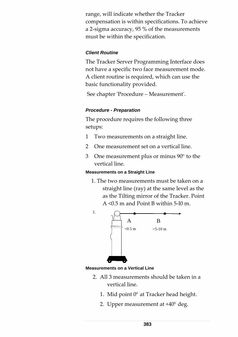
range, will indicate whether the Tracker compensation is within specifications. To achieve a 2‐sigma accuracy, 95 % of the measurements must be within the specification. Client Routine
The Tracker Server Programming Interface does not have a specific two face measurement mode. A client routine is required, which can use the basic functionality provided.
See chapter ʹProcedure – Measurementʹ. Procedure - Preparation
The procedure requires the following three setups:
1 Two measurements on a straight line.
2 One measurement set on a vertical line.
3 One measurement plus or minus 90° to the vertical line.
Measurements on a Straight Line
1. The two measurements must be taken on a straight line (ray) at the same level as the as the Tilting mirror of the Tracker. Point A <0.5 m and Point B within 5‐l0 m.
1.
<0.5 m >5-10 m
B A
Measurements on a Vertical Line
2. All 3 measurements should be taken in a vertical line.
1. Mid point 0° at Tracker head height.
2. Upper measurement at +40° deg.
383
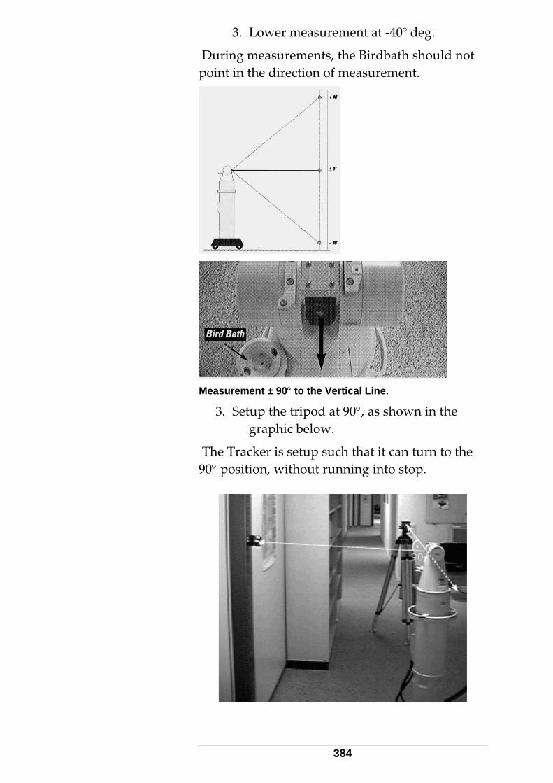
3. Lower measurement at ‐40° deg.
During measurements, the Birdbath should not point in the direction of measurement.
Measurement ± 90° to the Vertical Line.
3. Setup the tripod at 90°, as shown in the graphic below.
The Tracker is setup such that it can turn to the 90° position, without running into stop.
384
Procedure - Measurement
1. Set up the tracker.
2. Set the coordinate system type to spherical clock wise, SCW, TPI command: SetCoordinateSystemType.
3. Set the Stationary Measurement Mode. TPI command: SetMeasurementMode
4. Set the Stationary measurement parameter. MeasTime to 10000ms TPI command: SetStationaryModeParams
5. Attach the reflector to the target location.
6. Point the tracker to the target location. TPI command: e.g. GoPostion. This is only possible when the coordinates of the point are known within ± 2mm, otherwise track the reflector manually from the Bird bath.
7. Execute the Stationary Measurement in Face I and save it. TPI command: StartMeasurement
8. Execute the command Change Face, which puts the Laser Tracker from Face I to Face II. The pointing to a fixed reflector position from a station should be the same in both faces. TPI command: ChangeFace
9. Execute the Stationary Measurement in Face II and save it. TPI command: StartMeasurement.
10. Execute the command Change face, which puts the Laser Tracker from Face II to Face I. TPI command: ChangeFace.
11. Repeat the steps 5 ‐ 10 for all target locations.
Procedure - Calculation
Devvt = vertical angle Face I – vertical angle Face II
385
Devh = horizontal angle Face I – horizontal angle Face II
Both measurements are in Face I representation. Face II measurements are represented in Face I. Example
Devvt = 90.7289893– 90.7287338 = 0.0003 Deg Devh = 269.9877001– 269.9879985 = ‐0.0003 Deg Tolerances
The recommended tolerances of the deviations are:
Vertical angle = ±13cc (0.0012 Deg)
Horizontal angle = ±13cc (0.0012 Deg)
When the tolerance is exceeded, an Intermediate Compensation is recommended.
386
9 Mathematics
9.1 Point accuracy Throughout Emscon point coordinates are stored together with a 3x3 covariance matrix. It is a symmetric 3x3 matrix with the squares of the respective standard deviations on the diagonal:
2
1 122
12 2 232
13 23 3
stdDev covar covarcovar stdDev covarcovar covar stdDev
⎛ ⎞⎜ ⎟⎜ ⎟⎜ ⎟⎝ ⎠
13
The error ellipsoid of the point is defined by the eigenvectors and eigenvalues of the covariance matrix. If the covariance matrix is diagonal, the axes of the error ellipsoid are parallel to the coordinate axes. The correlations
*ij
iji j
covarstdDev stdDev
ρ =
satisfy the relations
1 1ijρ− ≤ ≤ .
At the TPI point coordinates together with the covariance matrix are passed in the following non‐redundant form:
.
Coord1, Coord2, Coord3, StdDev1, StdDev2, StdDev3, Covar12, Covar13, Covar23
9.1.1 A priori accuracy For continuous measurements, the a priori covariance matrix of a point measurement is calculated according to the tracker accuracy. Emscon adapts the following model:
387
2
max(1.25E-5/d, 5E-6)max(1.25E-5/d, 5E-6)
1E-10 + (1.25E-6 d)
StdDevHStdDevV
StdDevD
==
= ⋅
where d denotes the measured distance in meters. H and V denotes the horizontal and vertical angle in radians. This formula applies in the case of IFM measurements initialized at bird bath distance. The angle accuracy is constant beyond 2.5m and slightly poorer at close range. Simplified homogeneous models are
max(10E-6 d, 25 )StdDevXYZ μ= ⋅ or even simpler 50StdDevXYZ μ= . The a priori accuracy includes
unresolved systematic errors and indicates the reliability of a measurement. This kind of accuracy should be used as input to any further calculation. 9.1.2 A posteriori accuracy For single point measurements (stationary, sphere center, circle center) also the a posteriori or repeatability covariance is calculated from the actual statistical variation of the many shots. It gives an indication on the stability of the measurement environment disregarding systematic effects. We recommend not using this accuracy for any other purpose. 9.1.3 Transformation of covariance matrices In the (spherical) tracker coordinate system the a priori covariance matrix of a tracker measurement is diagonal (see formulas above). Conversion to Cartesian coordinates results in a full matrix. Transformation to other coordinate systems using orientation and/or transformation parameters (Section 9.2 below) again transforms the covariance matrix. However, at any stage the standard deviations, i.e. the square roots of the diagonal entries provide a reasonable estimate on the accuracy of the respective coordinate triple.
388
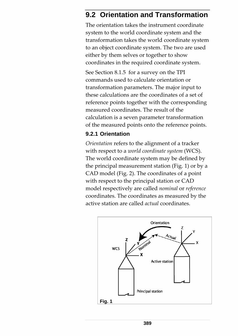
9.2 Orientation and Transformation The orientation takes the instrument coordinate system to the world coordinate system and the transformation takes the world coordinate system to an object coordinate system. The two are used either by them selves or together to show coordinates in the required coordinate system.
See Section 8.1.5 for a survey on the TPI commands used to calculate orientation or transformation parameters. The major input to these calculations are the coordinates of a set of reference points together with the corresponding measured coordinates. The result of the calculation is a seven parameter transformation of the measured points onto the reference points. 9.2.1 Orientation Orientation refers to the alignment of a tracker with respect to a world coordinate system (WCS). The world coordinate system may be defined by the principal measurement station (Fig. 1) or by a CAD model (Fig. 2). The coordinates of a point with respect to the principal station or CAD model respectively are called nominal or reference coordinates. The coordinates as measured by the active station are called actual coordinates.
Fig. 1
389
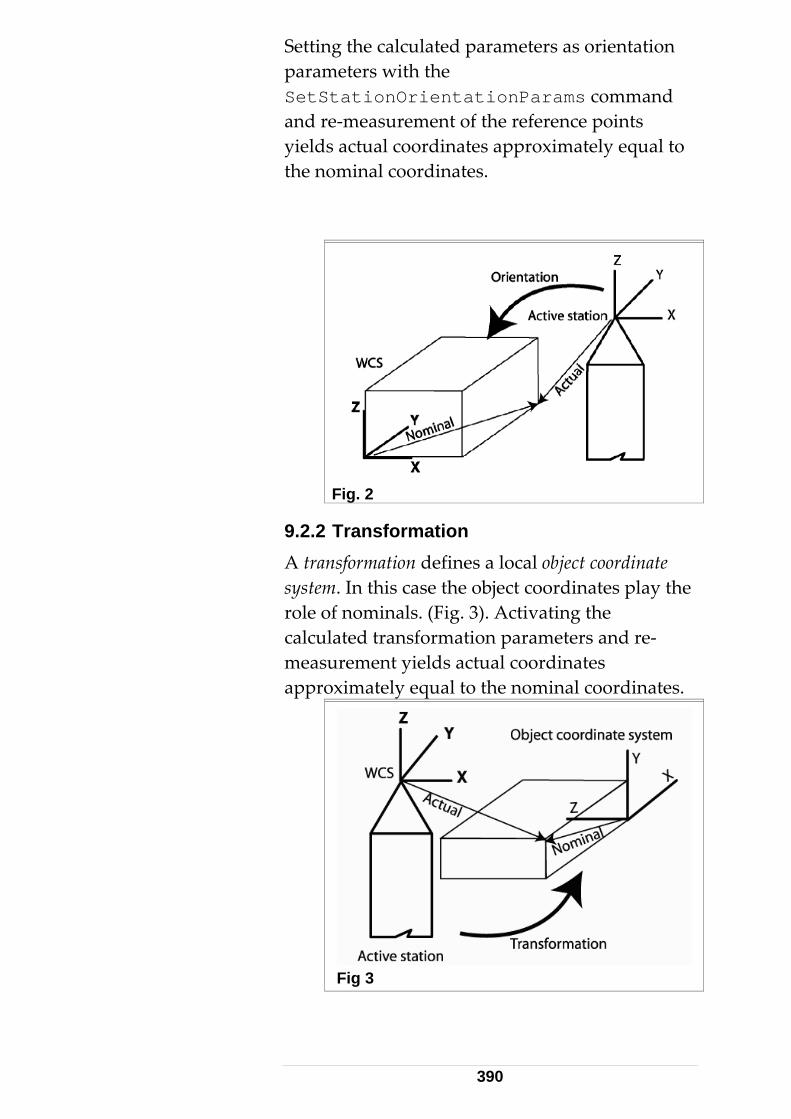
Setting the calculated parameters as orientation parameters with the SetStationOrientationParams command and re‐measurement of the reference points yields actual coordinates approximately equal to the nominal coordinates.
Fig. 2
9.2.2 Transformation A transformation defines a local object coordinate system. In this case the object coordinates play the role of nominals. (Fig. 3). Activating the calculated transformation parameters and re‐measurement yields actual coordinates approximately equal to the nominal coordinates.
Fig 3
390
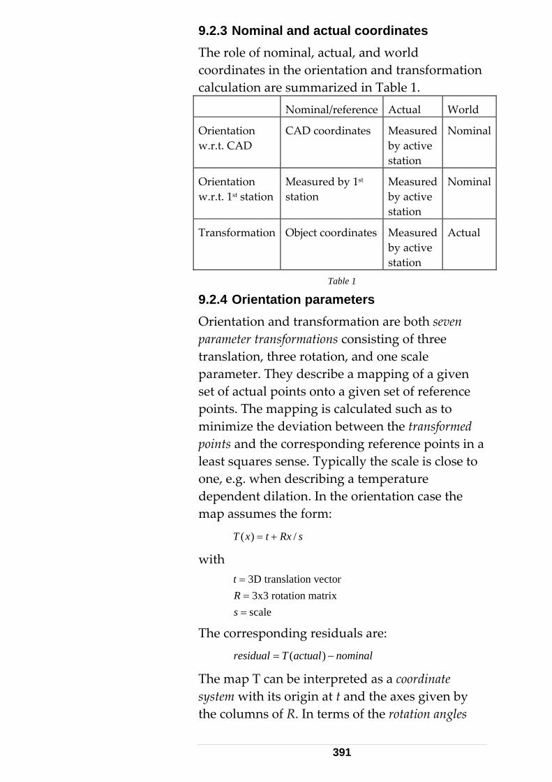
9.2.3 Nominal and actual coordinates The role of nominal, actual, and world coordinates in the orientation and transformation calculation are summarized in Table 1. Nominal/reference Actual World
Orientation w.r.t. CAD
CAD coordinates Measured by active station
Nominal
Orientation w.r.t. 1st station
Measured by 1st station
Measured by active station
Nominal
Transformation Object coordinates Measured by active station
Actual
Table 1
9.2.4 Orientation parameters Orientation and transformation are both seven parameter transformations consisting of three translation, three rotation, and one scale parameter. They describe a mapping of a given set of actual points onto a given set of reference points. The mapping is calculated such as to minimize the deviation between the transformed points and the corresponding reference points in a least squares sense. Typically the scale is close to one, e.g. when describing a temperature dependent dilation. In the orientation case the map assumes the form:
( ) /T x t Rx s= +
with
3D translation vector3x3 rotation matrix
scale
tRs
===
The corresponding residuals are:
( )residual T actual nominal= −
The map T can be interpreted as a coordinate system with its origin at t and the axes given by the columns of R. In terms of the rotation angles
391
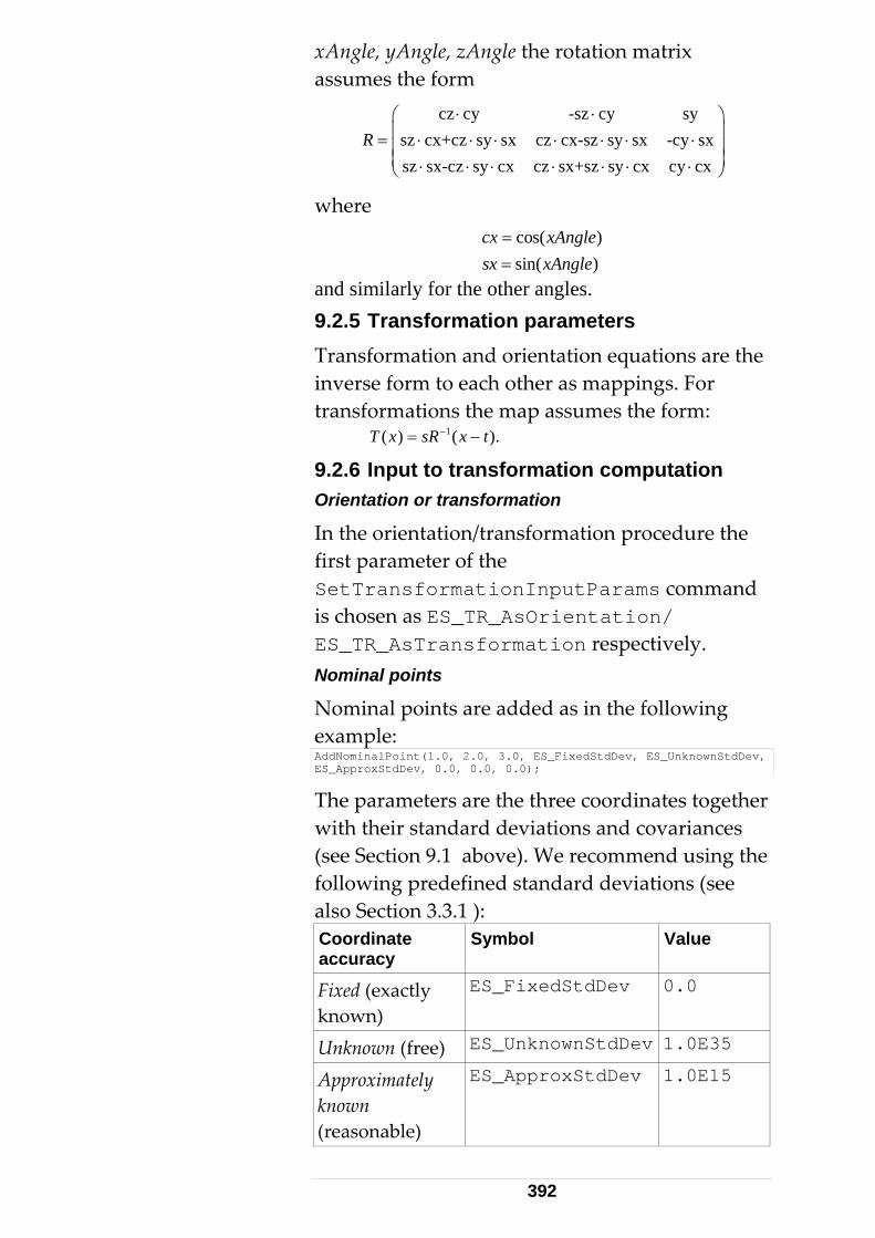
xAngle, yAngle, zAngle the rotation matrix assumes the form
cz cy -sz cy sy
sz cx+cz sy sx cz cx-sz sy sx -cy sxsz sx-cz sy cx cz sx+sz sy cx cy cx
R⋅ ⋅⎛ ⎞
⎜ ⎟= ⋅ ⋅ ⋅ ⋅ ⋅ ⋅ ⋅⎜ ⎟⎜ ⎟⋅ ⋅ ⋅ ⋅ ⋅ ⋅ ⋅⎝ ⎠
where
cos( )sin( )
cx xAnglesx xAngle
==
and similarly for the other angles. 9.2.5 Transformation parameters Transformation and orientation equations are the inverse form to each other as mappings. For transformations the map assumes the form:
1( ) ( ).T x sR x t−= −
9.2.6 Input to transformation computation Orientation or transformation
In the orientation/transformation procedure the first parameter of the SetTransformationInputParams command is chosen as ES_TR_AsOrientation/ ES_TR_AsTransformation respectively. Nominal points
Nominal points are added as in the following example: AddNominalPoint(1.0, 2.0, 3.0, ES_FixedStdDev, ES_UnknownStdDev, ES_ApproxStdDev, 0.0, 0.0, 0.0);
The parameters are the three coordinates together with their standard deviations and covariances (see Section 9.1 above). We recommend using the following predefined standard deviations (see also Section 3.3.1 ): Coordinate accuracy
Symbol Value
Fixed (exactly known)
ES_FixedStdDev 0.0
Unknown (free) ES_UnknownStdDev 1.0E35
ES_ApproxStdDev Approximately known (reasonable)
1.0E15
392
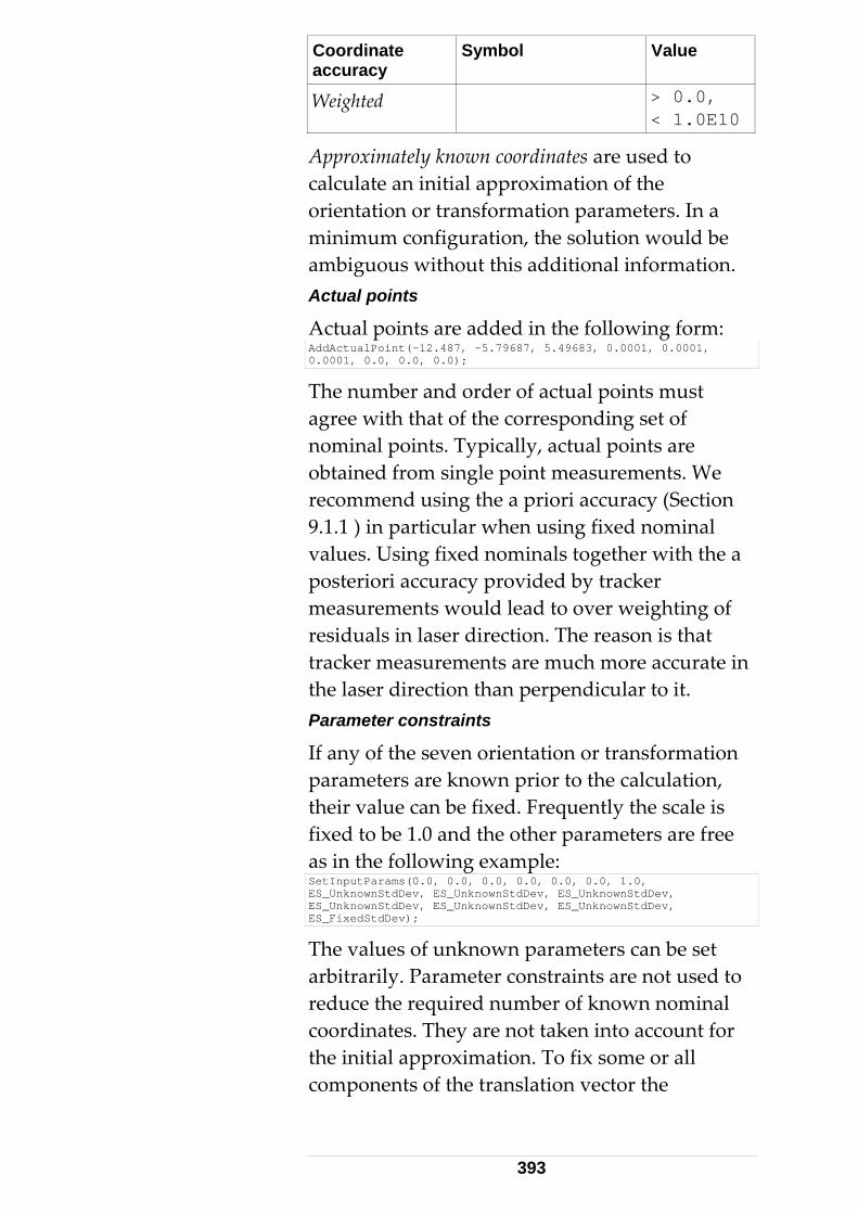
Coordinate accuracy
Symbol Value
> 0.0, Weighted < 1.0E10
Approximately known coordinates are used to calculate an initial approximation of the orientation or transformation parameters. In a minimum configuration, the solution would be ambiguous without this additional information. Actual points
Actual points are added in the following form: AddActualPoint(-12.487, -5.79687, 5.49683, 0.0001, 0.0001, 0.0001, 0.0, 0.0, 0.0);
The number and order of actual points must agree with that of the corresponding set of nominal points. Typically, actual points are obtained from single point measurements. We recommend using the a priori accuracy (Section 9.1.1 ) in particular when using fixed nominal values. Using fixed nominals together with the a posteriori accuracy provided by tracker measurements would lead to over weighting of residuals in laser direction. The reason is that tracker measurements are much more accurate in the laser direction than perpendicular to it. Parameter constraints
If any of the seven orientation or transformation parameters are known prior to the calculation, their value can be fixed. Frequently the scale is fixed to be 1.0 and the other parameters are free as in the following example: SetInputParams(0.0, 0.0, 0.0, 0.0, 0.0, 0.0, 1.0, ES_UnknownStdDev, ES_UnknownStdDev, ES_UnknownStdDev, ES_UnknownStdDev, ES_UnknownStdDev, ES_UnknownStdDev, ES_FixedStdDev);
The values of unknown parameters can be set arbitrarily. Parameter constraints are not used to reduce the required number of known nominal coordinates. They are not taken into account for the initial approximation. To fix some or all components of the translation vector the
393
coordinate type must be one of Cartesian RHR or LHR. 9.2.7 Output of transformation computation Transformation parameters
The command CallTransformation returns a structure CallTransformationRT containing the seven parameters of the transformation (translation, rotation angles, scale) together with their standard deviations. The standard deviation of a fixed parameter is zero. Transformed points and residuals
The command GetTransformedPoint returns a list of structures, each containing a transformed point together with its covariance matrix and the three coordinates of the residual vector
residual nominal transformed= − The covariance matrix of the transformed point takes into account the covariance matrix of the actual point and the 7 by 7 covariance matrix of the transformation calculated. The covariance matrix of the residual is obtained by adding those of the nominal and the transformed point. Statistics
The command CallTransformation also returns the
• RMS of residuals
• Maximum deviation
• Variance factor RMS of residuals
The RMS of residuals is defined as
2
1
n
ii
residualRMS
noEquations==∑
where the number of equations is the number of fixed or weighted nominal coordinates.
394
Maximum deviation
The maximum deviation is defined as
1..i n imaxDev max residual==
where fixed and weighted nominal coordinates are taken into account. Weighted residual square sum
The transformation algorithm determines the values of the transformation parameters in the weighted least squares sense. This means that the following target functional is minimized:
1
nT
i i ii
SS residual weightMatrix residual=
= ∑ R
This functional is called the weighted residual square sum. The weight matrix is the inverse of the covariance matrix of the residual. For constraints the residual and the weight matrix are scalars. Variance factor
The variance factor (Axyz: mean error) is related to the residual square sum through:
RSSvarianceFactor
redundancy=
It is dimensionless, i.e. it does not depend on the length or angle units. Its value may vary considerably depending on the accuracy of the input and the model error, i.e. the size of the residuals. If the residuals are systematically bigger than the standard deviations of the actual coordinates, the variance factor exceeds one. Otherwise, it is less than one. Redundancy
The redundancy is an integer defined as
redundancy noEquations noParameters= − .
If the redundancy is zero the variance factor is undefined. Such cases are called minimum configurations. If the redundancy is negative, the solution is non‐unique. More fixed nominal
395
coordinates or parameter constraints are needed to determine a unique solution. 9.2.8 Examples Standard case with 3 points AddNominalPoint(1, 2, 3, Fixed, Fixed, Fixed, 0, 0, 0); AddNominalPoint(2, 3, 4, Fixed, Fixed, Fixed, 0, 0, 0); AddNominalPoint(0, -4, 2, Fixed, Fixed, Fixed, 0, 0, 0); SetInputParams(0, 0, 0, 0, 0, 0, 1, Unknown, Unknown, Unknown, Unknown, Unknown, Unknown, Unknown);
In this example
3 7redundancy noPoints 2= ⋅ − = . Pure dilation AddNominalPoint(1, 1, 0, Fixed, Fixed, Fixed, 0, 0, 0); AddNominalPoint(-1, 1, 0, Fixed, Fixed, Fixed, 0, 0, 0); AddNominalPoint(1, -1, 0, Fixed, Fixed, Fixed, 0, 0, 0); AddNominalPoint(-1, -1, 0, Fixed, Fixed, Fixed, 0, 0, 0); AddActualPoint(1.1, 1.1, 0, 0.001, 0.001, 0.001, 0, 0, 0); AddActualPoint(-1.1, 1.1, 0, 0.001, 0.001, 0.001, 0, 0, 0); AddActualPoint(1.1, -1.1, 0, 0.001, 0.001, 0.001, 0, 0, 0); AddActualPoint(-1.1, -1.1, 0, 0.001, 0.001, 0.001, 0, 0, 0); SetInputParams(0, 0, 0, 0, 0, 0, 1, Unknown, Unknown, Unknown, Unknown, Unknown, Unknown, Fixed);
In this example the desired transformation is the identity with parameters 0, 0, 0, 0, 0, 0, 1. The length of all residuals is 0.1 2 . Their covariance matrix is
6
6
6
10 0 00 10 00 0 10
covar
−
−
−
⎛ ⎞⎜ ⎟= ⎜ ⎟⎜ ⎟⎝ ⎠
The weight matrix is
6
6
6
10 0 00 10 00 0 10
weight⎛ ⎞⎜ ⎟= ⎜ ⎟⎜ ⎟⎝ ⎠
Thus
( )264 * 10 * 0.1 2 80000
12 6 680000 13333.
6
RSS
redundancy
varianceFactor
= =
= − =
= =
Weighting
To illustrate the influence of nominal or actual standard deviations consider the following example.
396
AddNominalPoint(1.1, 1, 0, 0.002, Fixed, Fixed, 0, 0, 0); AddNominalPoint(1.1, -1, 0, 0.002, Fixed, Fixed, 0, 0, 0); AddNominalPoint(-1.1, 1, 0, 0.001, Fixed, Fixed, 0, 0, 0); AddNominalPoint(-1.1, -1, 0, 0.001, Fixed, Fixed, 0, 0, 0); AddActualPoint(1, 1, 0, 1.0E-35, 1.0E-35, 1.0E-35, 0, 0, 0); AddActualPoint(1, -1, 0, 1.0E-35, 1.0E-35, 1.0E-35, 0, 0, 0); AddActualPoint(-1, 1, 0, 1.0E-35, 1.0E-35, 1.0E-35, 0, 0, 0); AddActualPoint(-1, -1, 0, 1.0E-35, 1.0E-35, 1.0E-35, 0, 0, 0);
The resulting orientation has translation (‐0.06, 0, 0) and no rotation. The residual vectors are (‐0.16, 0, 0), (‐0.16, 0, 0) , (0.04, 0, 0) , (0.04, 0, 0). The weighted residuals (divide by square of standard deviation) have equal length 40000. 3-2-1 Alignment AddNominalPoint(1, 2, 3, Fixed, Fixed, Approx, 0, 0, 0); AddNominalPoint(2, 3, 4, Fixed, Fixed, Fixed, 0, 0, 0); AddNominalPoint(0, -4, 2, Approx, Fixed, Approx, 0, 0, 0); SetInputParams(0, 0, 0, 0, 0, 0, 1, Unknown, Unknown, Unknown, Unknown, Unknown, Unknown, Fixed);
This is a minimum configuration since
2 3 1 6 0.redundancy = + + − =
The approximate coordinates are necessary to select a unique solution from the eight possible solutions. This fact can be easily observed in the following example: AddNominalPoint(0, 0, 0, Fixed, Fixed, Fixed, 0, 0, 0); AddNominalPoint(1, 0, 0, Unknown, Fixed, Fixed, 0, 0, 0); AddNominalPoint(1, 1, 0, Unknown, Unknown, Fixed, 0, 0, 0);
Here each of the rotation angles can be 0 or π. The scale must be fixed in 3-2-1 situations. Box corner
The corner of a box is defined by three mutually perpendicular planes. In the subsequent example each plane contains two measured points. Only the nominal coordinate defining the plane is exactly known. AddNominalPoint(0, 1, 1, Fixed, Approx, Approx, 0, 0, 0); AddNominalPoint(0, 2, 2, Fixed, Approx, Approx, 0, 0, 0); AddNominalPoint(1, 0, 1, Approx, Fixed, Approx, 0, 0, 0); AddNominalPoint(1, 0, 2, Approx, Fixed, Approx, 0, 0, 0); AddNominalPoint(1, 1, 0, Approx, Approx, Fixed, 0, 0, 0); AddNominalPoint(2, 2, 0, Approx, Approx, Fixed, 0, 0, 0);
Again, this is a minimum configuration provided the scale is fixed. Orientation using Nivel measurement
Suppose the horizontal angles xAngle and yAngle have been obtained from a ʹNivelʹ measurement. To complete the orientation of the
397
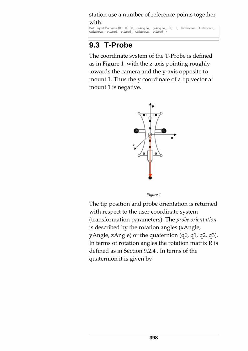
station use a number of reference points together with: SetInputParams(0, 0, 0, xAngle, yAngle, 0, 1, Unknown, Unknown, Unknown, Fixed, Fixed, Unknown, Fixed);
9.3 T-Probe The coordinate system of the T‐Probe is defined as in Figure 1 with the z‐axis pointing roughly towards the camera and the y‐axis opposite to mount 1. Thus the y coordinate of a tip vector at mount 1 is negative.
Figure 1
The tip position and probe orientation is returned with respect to the user coordinate system (transformation parameters). The probe orientation is described by the rotation angles (xAngle, yAngle, zAngle) or the quaternion (q0, q1, q2, q3). In terms of rotation angles the rotation matrix R is defined as in Section 9.2.4 . In terms of the quaternion it is given by
398
q0 q0+q1 q1-q2 q2-q3 q3Rxy=2(q1 q2-q0 q3)Rxz=2(q1 q3+q0 q2)Ryx=2(q1 q2+q0 q3)Ryy=q0 q0-q1 q1+q2 q2-q3 q3Ryz=2(q2 q3-q0 q1)Rzx=2(q1 q3-q0 q2)Rzy=2(q3 q2+q0 q1)Rzz=q0*q0-q1*q1-q2*q2+q3*q3
Rxx = ⋅ ⋅ ⋅ ⋅⋅ ⋅⋅ ⋅⋅ ⋅
⋅ ⋅ ⋅ ⋅⋅ ⋅⋅ ⋅⋅ ⋅
This matrix is used to transform directions from the probe coordinate system to the user system through:
* .directionUser R directionProbe= ___________________________________________ EmScon 3.0 TPI Programmers Manual - Revision: May 26, 2008
399
10 Appendices
10.1 Tracker Trigger Interface [A] Appendix A: A detailed description of Trigger‐ issues of the Tracker / emScon.
10.2 Server Error Numbers [B] Appendix B: This listing comprises the error numbers (and partly symbols) an emScon programmer may encounter for the ʹResultStatusʹ of TPI commands and/or TPI Error Events. It is meant as a Summary / Quick‐ Reference for information already documented in the main sections of the manual (but spread among several chapters). This listing applies to TPI errors that originate on the emScon server (i.e. not on Controller/Tracker Firmware)
10.3 Tracker / TP Error Numbers [C] Appendix C: This listing comprises the error numbers an emScon programmer may encounter for the ʹResultStatusʹ of TPI commands and/or TPI Error Events. The errors listed here originate at the Tracker or Tracker‐ Processor. (In contrast to those listed in Appendix B, which originate on the emScon server). Thus Appendix C extends the listing of Appendix B.
10.4 T-Cam / T-Probe Error Numbers [D] Appendix D: This listing continues and extends the list of Appendix C. While the list under Appendix C was related to Tracker/TP hardware only, this list covers ʹExtension‐ Hardwareʹ, such as T‐Cam and T‐Probe.
400
10.5 AIFM Error Numbers [E] Appendix E: This listing continues and extends the list of Appendix C. It contains new error numbers specific to emScon 3.0. These numbers are related to the new AIFM (Absolute Interferometer) hardware of AT‐ Tracker series.
401
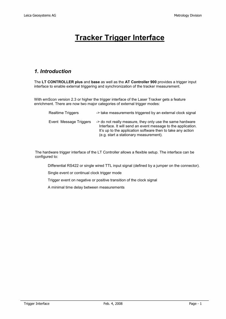
Leica Geosystems AG Metrology Division
Trigger Interface Feb. 4, 2008 Page - 1
Tracker Trigger Interface
1. Introduction The LT CONTROLLER plus and base as well as the AT Controller 900 provides a trigger input interface to enable external triggering and synchronization of the tracker measurement.
With emScon version 2.3 or higher the trigger interface of the Laser Tracker gets a feature enrichment. There are now two major categories of external trigger modes:
• Realtime Triggers -> take measurements triggered by an external clock signal
• Event Message Triggers -> do not really measure, they only use the same hardware Interface. It will send an event message to the application. It’s up to the application software then to take any action (e.g. start a stationary measurement).
The hardware trigger interface of the LT Controller allows a flexible setup. The interface can be configured to:
• Differential RS422 or single wired TTL input signal (defined by a jumper on the connector).
• Single event or continual clock trigger mode
• Trigger event on negative or positive transition of the clock signal
• A minimal time delay between measurements
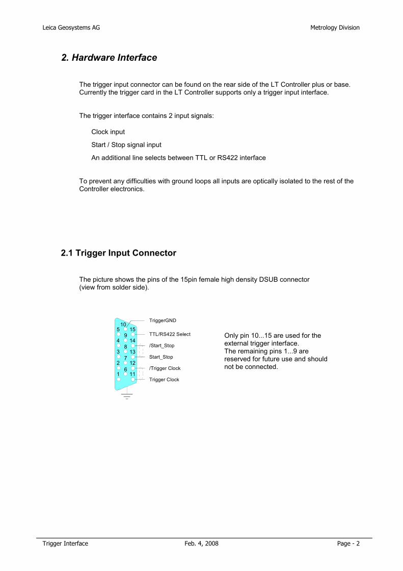
Leica Geosystems AG Metrology Division
Trigger Interface Feb. 4, 2008 Page - 2
2. Hardware Interface
The trigger input connector can be found on the rear side of the LT Controller plus or base. Currently the trigger card in the LT Controller supports only a trigger input interface.
The trigger interface contains 2 input signals:
• Clock input
• Start / Stop signal input
• An additional line selects between TTL or RS422 interface
To prevent any difficulties with ground loops all inputs are optically isolated to the rest of the Controller electronics.
2.1 Trigger Input Connector
The picture shows the pins of the 15pin female high density DSUB connector (view from solder side).
Only pin 10...15 are used for the external trigger interface. The remaining pins 1...9 are reserved for future use and should not be connected.
TriggerGND
/Trigger Clock
Start_Stop
/Start_Stop
Trigger Clock
TTL/RS422 Select
1
2
3
4
5
6
7
8
9
10
11
12
14
15
13
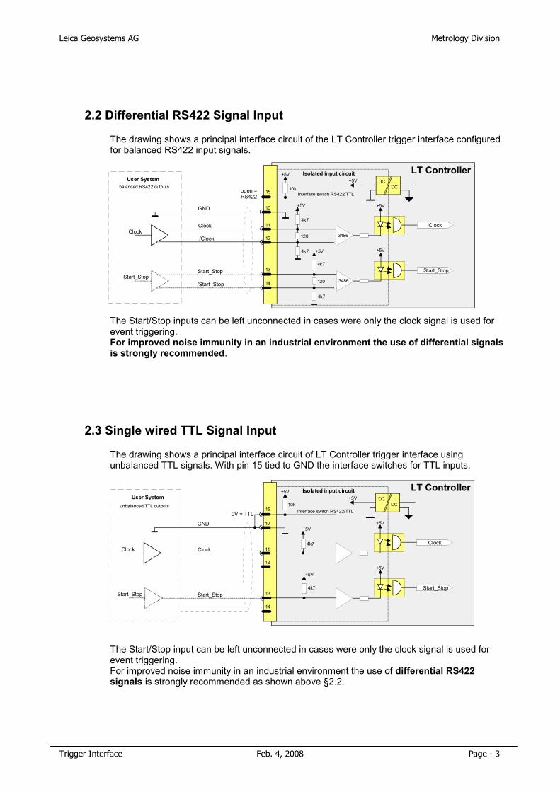
Leica Geosystems AG Metrology Division
Trigger Interface Feb. 4, 2008 Page - 3
2.2 Differential RS422 Signal Input
The drawing shows a principal interface circuit of the LT Controller trigger interface configured for balanced RS422 input signals.
The Start/Stop inputs can be left unconnected in cases were only the clock signal is used for event triggering. For improved noise immunity in an industrial environment the use of differential signals is strongly recommended.
2.3 Single wired TTL Signal Input
The drawing shows a principal interface circuit of LT Controller trigger interface using unbalanced TTL signals. With pin 15 tied to GND the interface switches for TTL inputs.
The Start/Stop input can be left unconnected in cases were only the clock signal is used for event triggering. For improved noise immunity in an industrial environment the use of differential RS422 signals is strongly recommended as shown above §2.2.
DC DC
+5V
Clock
+5V
Start_Stop
+5V
3486
+5V
10k
120
4k7
4k7
+5V
+5V
3486120
4k7
4k7
Interface switch RS422/TTL
Isolated input circuit LT Controller
11
12
13
14
15
10
Clock
Start_Stop
Clock
Start_Stop
/Clock
/Start_Stop
open = RS422
GND
User Systembalanced RS422 outputs
DC DC
+5V
Clock
+5V
Start_Stop
+5V
+5V
10k
4k7
+5V
+5V
4k7
Interface switch RS422/TTL
Isolated input circuit LT Controller
11
12
13
14
15
10
Clock
Start_Stop
Clock
Start_Stop
0V = TTL
GND
User Systemunbalanced TTL outputs
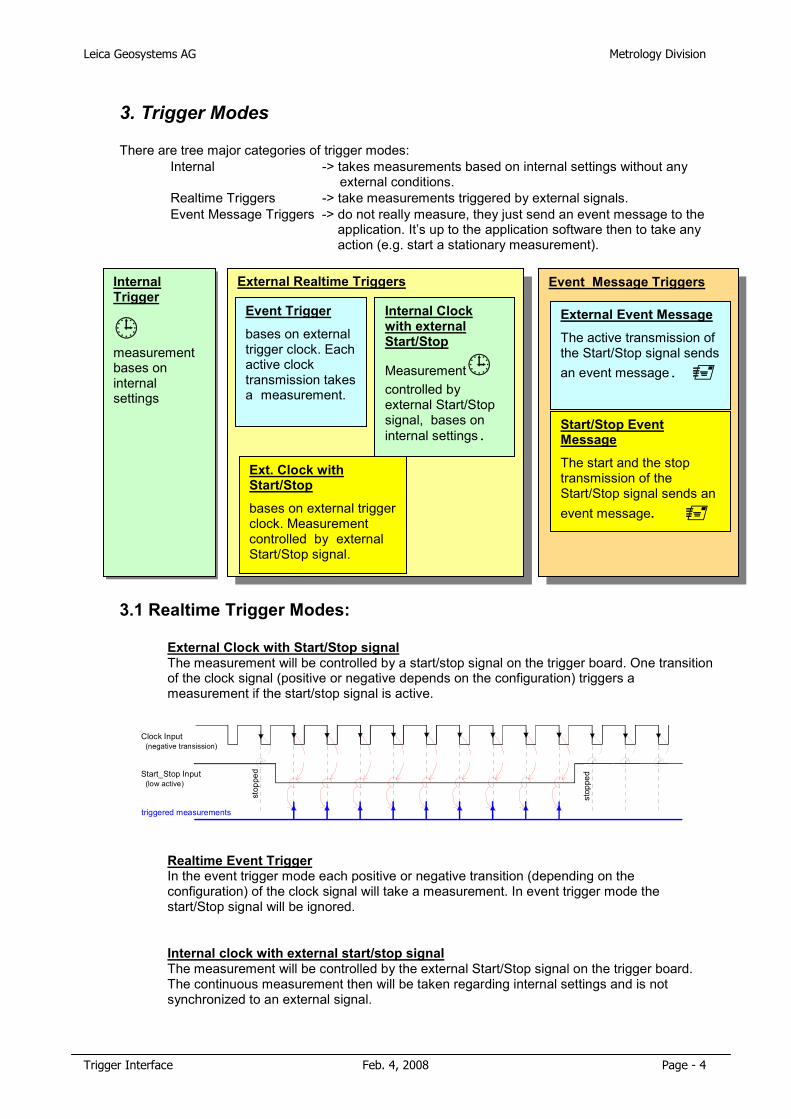
Leica Geosystems AG Metrology Division
Trigger Interface Feb. 4, 2008 Page - 4
3. Trigger Modes There are tree major categories of trigger modes:
• Internal -> takes measurements based on internal settings without any external conditions.
• Realtime Triggers -> take measurements triggered by external signals. • Event Message Triggers -> do not really measure, they just send an event message to the
application. It’s up to the application software then to take any action (e.g. start a stationary measurement).
3.1 Realtime Trigger Modes:
• External Clock with Start/Stop signalThe measurement will be controlled by a start/stop signal on the trigger board. One transition of the clock signal (positive or negative depends on the configuration) triggers a measurement if the start/stop signal is active.
• Realtime Event TriggerIn the event trigger mode each positive or negative transition (depending on the configuration) of the clock signal will take a measurement. In event trigger mode the start/Stop signal will be ignored.
• Internal clock with external start/stop signalThe measurement will be controlled by the external Start/Stop signal on the trigger board. The continuous measurement then will be taken regarding internal settings and is not synchronized to an external signal.
Event Message TriggersInternal Trigger
�measurement bases on internal settings
External Realtime Triggers
Event Trigger
bases on external trigger clock. Each active clock transmission takes a measurement.
Internal Clock with external Start/Stop
Measurement�controlled by external Start/Stop signal, bases on internal settings.
External Event Message
The active transmission of the Start/Stop signal sends an event message. �
Start/Stop Event Message
The start and the stop transmission of the Start/Stop signal sends an event message. �
Ext. Clock with Start/Stop
bases on external trigger clock. Measurement controlled by external Start/Stop signal.
stop
ped
triggered measurements
Start_Stop Input (low active)
Clock Input (negative transission)
stop
ped
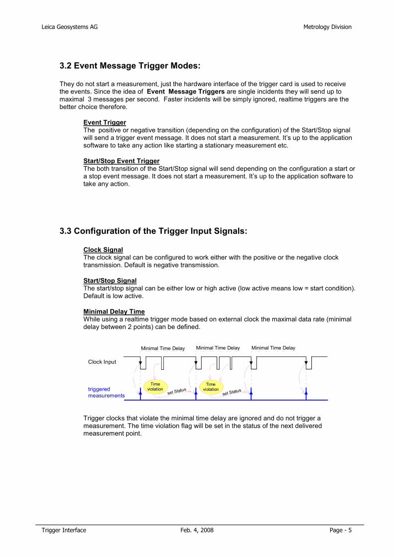
Leica Geosystems AG Metrology Division
Trigger Interface Feb. 4, 2008 Page - 5
3.2 Event Message Trigger Modes: They do not start a measurement, just the hardware interface of the trigger card is used to receive the events. Since the idea of Event Message Triggers are single incidents they will send up to maximal 3 messages per second. Faster incidents will be simply ignored, realtime triggers are the better choice therefore.
• Event TriggerThe positive or negative transition (depending on the configuration) of the Start/Stop signal will send a trigger event message. It does not start a measurement. It’s up to the application software to take any action like starting a stationary measurement etc.
• Start/Stop Event TriggerThe both transition of the Start/Stop signal will send depending on the configuration a start or a stop event message. It does not start a measurement. It’s up to the application software to take any action.
3.3 Configuration of the Trigger Input Signals:
• Clock SignalThe clock signal can be configured to work either with the positive or the negative clock transmission. Default is negative transmission.
• Start/Stop Signal
The start/stop signal can be either low or high active (low active means low = start condition). Default is low active.
• Minimal Delay Time
While using a realtime trigger mode based on external clock the maximal data rate (minimal delay between 2 points) can be defined.
Trigger clocks that violate the minimal time delay are ignored and do not trigger a measurement. The time violation flag will be set in the status of the next delivered measurement point.
Timeviolation
Timeviolationtriggered
measurements
Clock Input
Minimal Time Delay
set Status
Minimal Time Delay
set Status
Minimal Time Delay
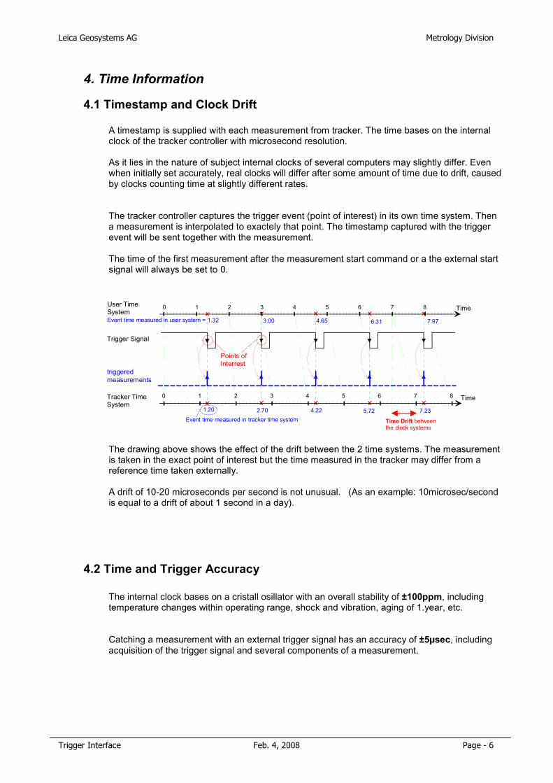
Leica Geosystems AG Metrology Division
Trigger Interface Feb. 4, 2008 Page - 6
4. Time Information
4.1 Timestamp and Clock Drift
A timestamp is supplied with each measurement from tracker. The time bases on the internal clock of the tracker controller with microsecond resolution. As it lies in the nature of subject internal clocks of several computers may slightly differ. Even when initially set accurately, real clocks will differ after some amount of time due to drift, caused by clocks counting time at slightly different rates.
The tracker controller captures the trigger event (point of interest) in its own time system. Then a measurement is interpolated to exactely that point. The timestamp captured with the trigger event will be sent together with the measurement. The time of the first measurement after the measurement start command or a the external start signal will always be set to 0.
The drawing above shows the effect of the drift between the 2 time systems. The measurement is taken in the exact point of interest but the time measured in the tracker may differ from a reference time taken externally. A drift of 10-20 microseconds per second is not unusual. (As an example: 10microsec/second is equal to a drift of about 1 second in a day).
4.2 Time and Trigger Accuracy
The internal clock bases on a cristall osillator with an overall stability of ±100ppm, including temperature changes within operating range, shock and vibration, aging of 1.year, etc.
Catching a measurement with an external trigger signal has an accuracy of ±5µsec, including acquisition of the trigger signal and several components of a measurement.
triggered measurements
Trigger Signal
TimeUser Time System
TimeTracker Time System
1.20 2.70 4.22 5.72
0 1 2 3 4 5 6 7 8
0 1 2 3 4 5 6 7 8
7.23
1.32 3.00 4.65 6.31 7.97
Time Drift betweenthe clock systems
Event time measured in tracker time system
Event time measured in user system =
Points of Interrest
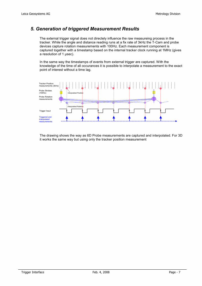
Leica Geosystems AG Metrology Division
Trigger Interface Feb. 4, 2008 Page - 7
5. Generation of triggered Measurement Results
The external trigger signal does not directely influence the raw measureing process in the tracker. While the angle and distance reading runs at a fix rate of 3kHz the T-Cam and probe devices capture rotation measurements with 100Hz. Each measurement component is captured together with a timestamp based on the internal tracker clock running at 1MHz (gives a resolution of 1 µsec). In the same way the timestamps of events from external trigger are captured. With the knowledge of the time of all occurances it is possible to interpolate a measurement to the exact point of interest without a time lag.
The drawing shows the way as 6D Probe measurements are captured and interpolated. For 3D it works the same way but using only the tracker position measurement
Interpolated Rotation
Probe Strobes(100Hz)
Tracker Position measurements (3kHz)
Probe Rotation measurements
Triggered and interpolated measurements
Trigger Input
Interpolated Position
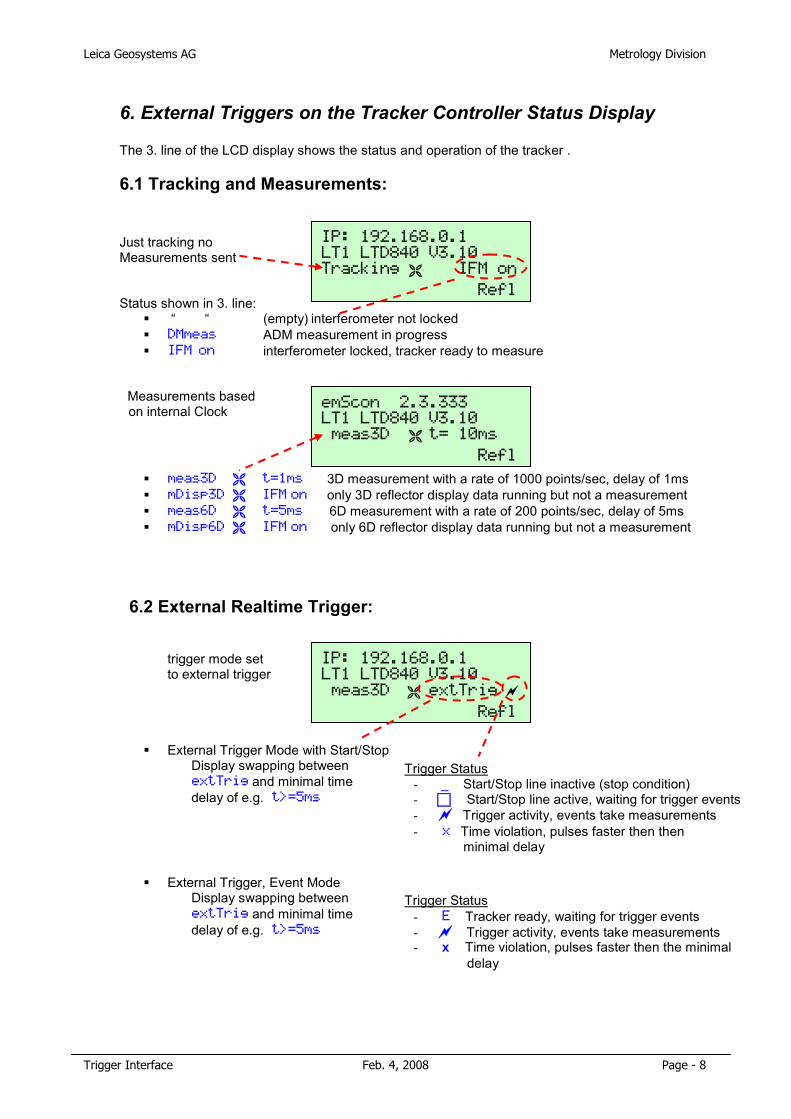
Leica Geosystems AG Metrology Division
Trigger Interface Feb. 4, 2008 Page - 8
6. External Triggers on the Tracker Controller Status Display
The 3. line of the LCD display shows the status and operation of the tracker .
6.1 Tracking and Measurements:
Just tracking no Measurements sent
Status shown in 3. line: � “ “ (empty) interferometer not locked � DMmeas ADM measurement in progress � IFM on interferometer locked, tracker ready to measure
Measurements based on internal Clock
� meas3D � t=1ms 3D measurement with a rate of 1000 points/sec, delay of 1ms � mDisp3D � IFM on only 3D reflector display data running but not a measurement � meas6D � t=5ms 6D measurement with a rate of 200 points/sec, delay of 5ms � mDisp6D � IFM on only 6D reflector display data running but not a measurement
6.2 External Realtime Trigger:
trigger mode set to external trigger
� External Trigger Mode with Start/Stop Display swapping between extTrig and minimal time delay of e.g. t>=5ms
� External Trigger, Event Mode Display swapping between extTrig and minimal time delay of e.g. t>=5ms
IP: 192.168.0.1 LT1 LTD840 V3.10 meas3D � extTrig �
. ... Refl
IP: 192.168.0.1 LT1 LTD840 V3.10 Tracking � IFM on
. ... Refl
emScon 2.3.333 LT1 LTD840 V3.10 meas3D � t= 10ms
. ... Refl
Trigger Status - _ Start/Stop line inactive (stop condition) - � Start/Stop line active, waiting for trigger events - � Trigger activity, events take measurements - x Time violation, pulses faster then then
minimal delay
Trigger Status - E Tracker ready, waiting for trigger events - � Trigger activity, events take measurements - x Time violation, pulses faster then the minimal
delay
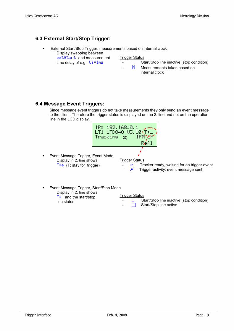
Leica Geosystems AG Metrology Division
Trigger Interface Feb. 4, 2008 Page - 9
6.3 External Start/Stop Trigger:
� External Start/Stop Trigger, measurements based on internal clock Display swapping between extStart and measurement time delay of e.g. ti=1ms
6.4 Message Event Triggers: Since message event triggers do not take measurements they only send an event message to the client. Therefore the trigger status is displayed on the 2. line and not on the operation line in the LCD display.
� Event Message Trigger, Event Mode Display in 2. line shows T:e (T: stay for trigger)
� Event Message Trigger, Start/Stop Mode Display in 2. line shows T: and the start/stop line status
IP: 192.168.0.1 LT1 LTD840 V3.10 T:_ Tracking � IFM on
. ... Refl
Trigger Status - _ Start/Stop line inactive (stop condition) - M Measurements taken based on
internal clock
Trigger Status - e Tracker ready, waiting for an trigger event - � Trigger activity, event message sent
Trigger Status - _ Start/Stop line inactive (stop condition) - � Start/Stop line active
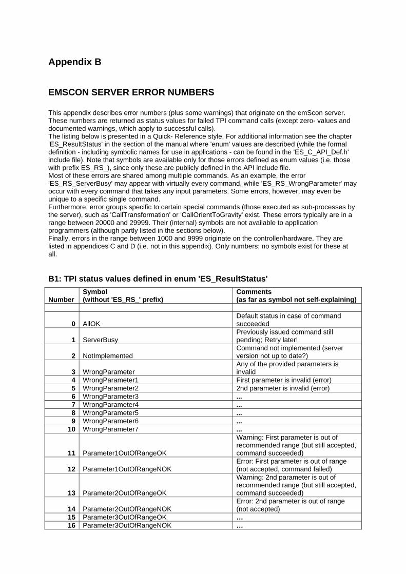
Appendix B
EMSCON SERVER ERROR NUMBERS This appendix describes error numbers (plus some warnings) that originate on the emScon server. These numbers are returned as status values for failed TPI command calls (except zero- values and documented warnings, which apply to successful calls). The listing below is presented in a Quick- Reference style. For additional information see the chapter 'ES_ResultStatus' in the section of the manual where 'enum' values are described (while the formal definition - including symbolic names for use in applications - can be found in the 'ES_C_API_Def.h' include file). Note that symbols are available only for those errors defined as enum values (i.e. those with prefix ES_RS_), since only these are publicly defined in the API include file. Most of these errors are shared among multiple commands. As an example, the error 'ES_RS_ServerBusy' may appear with virtually every command, while 'ES_RS_WrongParameter' may occur with every command that takes any input parameters. Some errors, however, may even be unique to a specific single command. Furthermore, error groups specific to certain special commands (those executed as sub-processes by the server), such as 'CallTransformation' or 'CallOrientToGravity' exist. These errors typically are in a range between 20000 and 29999. Their (internal) symbols are not available to application programmers (although partly listed in the sections below). Finally, errors in the range between 1000 and 9999 originate on the controller/hardware. They are listed in appendices C and D (i.e. not in this appendix). Only numbers; no symbols exist for these at all.
B1: TPI status values defined in enum 'ES_ResultStatus'
Number Symbol (without 'ES_RS_' prefix)
Comments (as far as symbol not self-explaining)
0 AllOK Default status in case of command succeeded
1 ServerBusy Previously issued command still pending; Retry later!
2 NotImplemented Command not implemented (server version not up to date?)
3 WrongParameter Any of the provided parameters is invalid
4 WrongParameter1 First parameter is invalid (error) 5 WrongParameter2 2nd parameter is invalid (error) 6 WrongParameter3 ... 7 WrongParameter4 ... 8 WrongParameter5 ... 9 WrongParameter6 ...
10 WrongParameter7 ...
11 Parameter1OutOfRangeOK
Warning: First parameter is out of recommended range (but still accepted, command succeeded)
12 Parameter1OutOfRangeNOK Error: First parameter is out of range (not accepted, command failed)
13 Parameter2OutOfRangeOK
Warning: 2nd parameter is out of recommended range (but still accepted, command succeeded)
14 Parameter2OutOfRangeNOK Error: 2nd parameter is out of range (not accepted)
15 Parameter3OutOfRangeOK … 16 Parameter3OutOfRangeNOK …

17 Parameter4OutOfRangeOK … 18 Parameter4OutOfRangeNOK … 19 Parameter5OutOfRangeOK … 20 Parameter5OutOfRangeNOK … 21 Parameter6OutOfRangeOK … 22 Parameter6OutOfRangeNOK …
23 WrongCurrentReflector Current Reflector type is not suitable in current context
24 NoCircleCenterFound
Applies to Circle Center measurement modes only. Failed to calculate the center (usually bad or not enough measurements)
25 NoSphereCenterFound
Applies to Sphere Center measurement modes only. Failed to calculate the center (usually bad or not enough measurements)
26 NoTPFound Tracker Processor (Controller) not detected. Missing cable?
27 NoWeathermonitorFound Tried to query meteo data from (missing or disabled) external meteo device
28 NoLastMeasuredPoint
Applies to command 'GoLastMeasuredPoint' only. No point has been measured yet since last system start.
29 NoVideoCamera Tried to access Video functionality, but there is no overview video camera
30 NoAdm Tried to access ADM functionality, but tracker is not equipped with an ADM
31 NoNivel
Tried to access Level functionality, while no inclination sensor (Nivel) is attached/enabled
32 WrongTPFirmware Current firmware is not suitable for actual tracker/controller
33 DataBaseNotFound
Fatal installation problem on emScon server (SQL server not running or no DB attached)
34 LicenseExpired The copy-protection Dongle has expired
35 UsageConflict The issued command does not make sense in current context
36 Unknown An unknown / not specified error has occurred
37 NoDistanceSet
Tried to measure HVD while IFM distance not set - use 'GoBirdBath' or 'GoPosition'/'FindReflector'
38 NoTrackerConnected Tracker not recognized (cable connection problem?)
39 TrackerNotInitialized
Any command that throws this error requires the tracker being initialized first. Issue 'Initialize' command first.
40 ModuleNotStarted
Applies to a child-process: Transformation, OrientToGravity… Should normally not happen (hanging process?) System may require a reboot
41 ModuleTimedOut Applies to a child-process: No response within reasonable time
42 ErrorReadingModuleDb Fatal database failure (database file corrupt?)
43 ErrorWritingModuleDb Fatal database failure (disk full?)
44 NotInCameraPosition Video Camera cannot deliver image due wrong (mirror) position - use
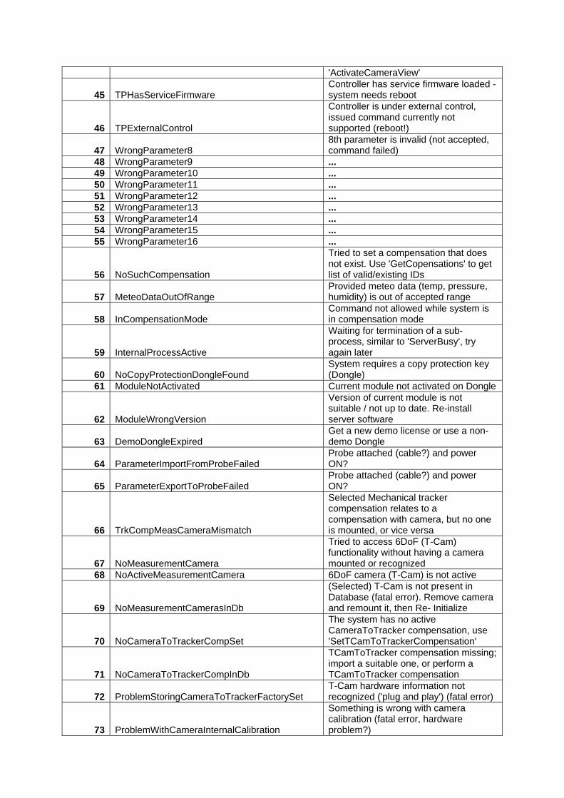
'ActivateCameraView'
45 TPHasServiceFirmware Controller has service firmware loaded - system needs reboot
46 TPExternalControl
Controller is under external control, issued command currently not supported (reboot!)
47 WrongParameter8 8th parameter is invalid (not accepted, command failed)
48 WrongParameter9 ... 49 WrongParameter10 ... 50 WrongParameter11 ... 51 WrongParameter12 ... 52 WrongParameter13 ... 53 WrongParameter14 ... 54 WrongParameter15 ... 55 WrongParameter16 ...
56 NoSuchCompensation
Tried to set a compensation that does not exist. Use 'GetCopensations' to get list of valid/existing IDs
57 MeteoDataOutOfRange Provided meteo data (temp, pressure, humidity) is out of accepted range
58 InCompensationMode Command not allowed while system is in compensation mode
59 InternalProcessActive
Waiting for termination of a sub- process, similar to 'ServerBusy', try again later
60 NoCopyProtectionDongleFound System requires a copy protection key (Dongle)
61 ModuleNotActivated Current module not activated on Dongle
62 ModuleWrongVersion
Version of current module is not suitable / not up to date. Re-install server software
63 DemoDongleExpired Get a new demo license or use a non- demo Dongle
64 ParameterImportFromProbeFailed Probe attached (cable?) and power ON?
65 ParameterExportToProbeFailed Probe attached (cable?) and power ON?
66 TrkCompMeasCameraMismatch
Selected Mechanical tracker compensation relates to a compensation with camera, but no one is mounted, or vice versa
67 NoMeasurementCamera
Tried to access 6DoF (T-Cam) functionality without having a camera mounted or recognized
68 NoActiveMeasurementCamera 6DoF camera (T-Cam) is not active
69 NoMeasurementCamerasInDb
(Selected) T-Cam is not present in Database (fatal error). Remove camera and remount it, then Re- Initialize
70 NoCameraToTrackerCompSet
The system has no active CameraToTracker compensation, use 'SetTCamToTrackerCompensation'
71 NoCameraToTrackerCompInDb
TCamToTracker compensation missing; import a suitable one, or perform a TCamToTracker compensation
72 ProblemStoringCameraToTrackerFactorySet T-Cam hardware information not recognized ('plug and play') (fatal error)
73 ProblemWithCameraInternalCalibration
Something is wrong with camera calibration (fatal error, hardware problem?)
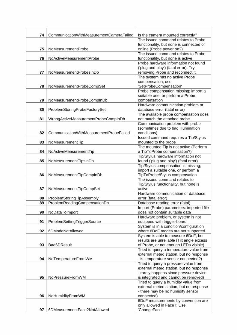
74 CommunicationWithMeasurementCameraFailed Is the camera mounted correctly?
75 NoMeasurementProbe
The issued command relates to Probe functionality, but none is connected or online (Probe power on?)
76 NoActiveMeasurementProbe The issued command relates to Probe functionality, but none is active
77 NoMeasurementProbesInDb
Probe hardware information not found ('plug and play') (fatal error). Try removing Probe and reconnect it.
78 NoMeasurementProbeCompSet
The system has no active Probe compensation, use 'SetProbeCompensation'
79 NoMeasurementProbeCompInDb,
Probe compensation missing; import a suitable one, or perform a Probe compensation
80 ProblemStoringProbeFactorySet Hardware communication problem or database error (fatal error)
81 WrongActiveMeasurementProbeCompInDb The available probe compensation does not match the attached probe
82 CommunicationWithMeasurementProbeFailed
Communication problem with probe (sometimes due to bad Illumination conditions)
83 NoMeasurementTip Issued command requires a Tip/Stylus mounted to the probe
84 NoActiveMeasurementTip The mounted Tip is not active (Perform a TipToProbe compensation?)
85 NoMeasurementTipsInDb Tip/Stylus hardware information not found ('plug and play') (fatal error)
86 NoMeasurementTipCompInDb
Tip/Stylus compensation is missing; import a suitable one, or perform a TipToProbe/Stylus compensation
87 NoMeasurementTipCompSet
The issued command relates to Tip/Stylus functionality, but none is active
88 ProblemStoringTipAssembly Hardware communication or database error (fatal error)
89 ProblemReadingCompensationDb Database reading error (fatal)
90 NoDataToImport Import (Probe) parameters: imported file does not contain suitable data
91 ProblemSettingTriggerSource Hardware problem, or system is not equipped with trigger-board
92 6DModeNotAllowed System is in a condition/configuration where 6DoF modes are not supported
93 Bad6DResult
System is able to measure 6DoF, but results are unreliable (Tilt angle excess of Probe, or not enough LEDs visible)
94 NoTemperatureFromWM
Tried to query a temperature value from external meteo station, but no response - is temperature sensor connected?)
95 NoPressureFromWM
Tried to query a pressure value from external meteo station, but no response - rarely happens since pressure device is integrated and cannot be removed)
96 NoHumidityFromWM
Tried to query a humidity value from external meteo station, but no response - there may be no humidity sensor connected)
97 6DMeasurementFace2NotAllowed
6DoF measurements by convention are only allowed in Face I; Use 'ChangeFace'
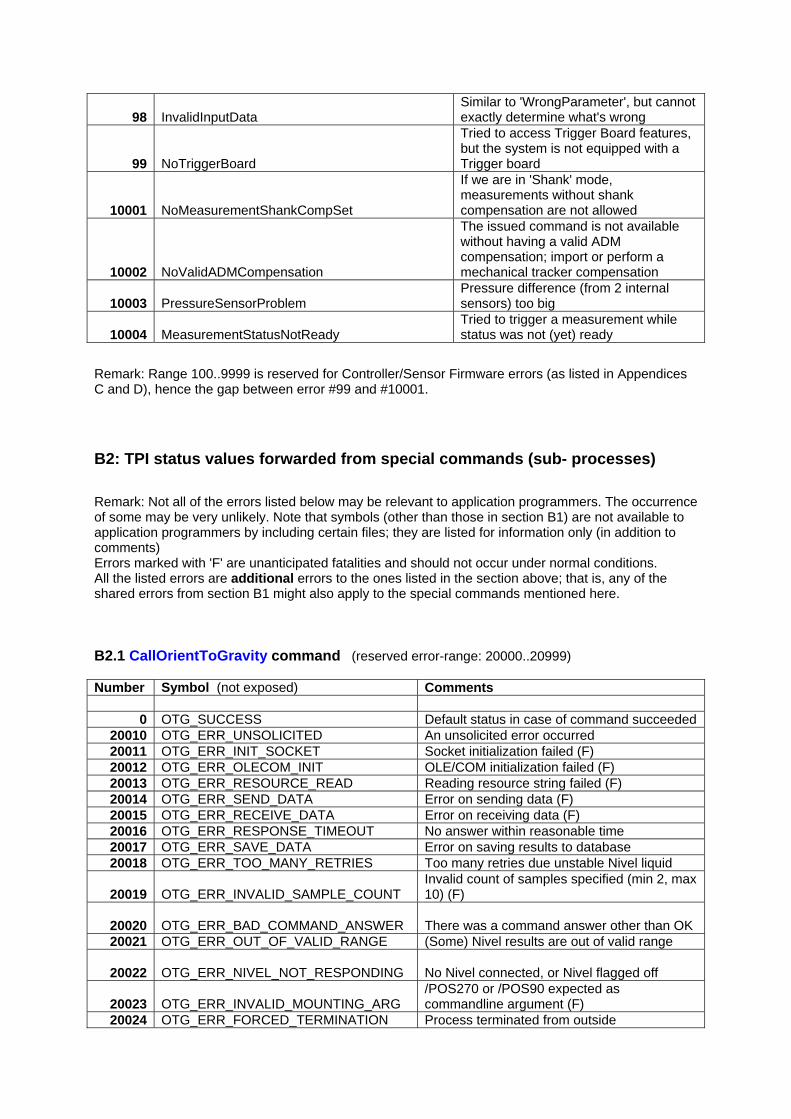
98 InvalidInputData Similar to 'WrongParameter', but cannot exactly determine what's wrong
99 NoTriggerBoard
Tried to access Trigger Board features, but the system is not equipped with a Trigger board
10001 NoMeasurementShankCompSet
If we are in 'Shank' mode, measurements without shank compensation are not allowed
10002 NoValidADMCompensation
The issued command is not available without having a valid ADM compensation; import or perform a mechanical tracker compensation
10003 PressureSensorProblem Pressure difference (from 2 internal sensors) too big
10004 MeasurementStatusNotReady Tried to trigger a measurement while status was not (yet) ready
Remark: Range 100..9999 is reserved for Controller/Sensor Firmware errors (as listed in Appendices C and D), hence the gap between error #99 and #10001. B2: TPI status values forwarded from special commands (sub- processes) Remark: Not all of the errors listed below may be relevant to application programmers. The occurrence of some may be very unlikely. Note that symbols (other than those in section B1) are not available to application programmers by including certain files; they are listed for information only (in addition to comments) Errors marked with 'F' are unanticipated fatalities and should not occur under normal conditions. All the listed errors are additional errors to the ones listed in the section above; that is, any of the shared errors from section B1 might also apply to the special commands mentioned here. B2.1 CallOrientToGravity command (reserved error-range: 20000..20999) Number Symbol (not exposed) Comments
0 OTG_SUCCESS Default status in case of command succeeded 20010 OTG_ERR_UNSOLICITED An unsolicited error occurred 20011 OTG_ERR_INIT_SOCKET Socket initialization failed (F) 20012 OTG_ERR_OLECOM_INIT OLE/COM initialization failed (F) 20013 OTG_ERR_RESOURCE_READ Reading resource string failed (F) 20014 OTG_ERR_SEND_DATA Error on sending data (F) 20015 OTG_ERR_RECEIVE_DATA Error on receiving data (F) 20016 OTG_ERR_RESPONSE_TIMEOUT No answer within reasonable time 20017 OTG_ERR_SAVE_DATA Error on saving results to database 20018 OTG_ERR_TOO_MANY_RETRIES Too many retries due unstable Nivel liquid
20019 OTG_ERR_INVALID_SAMPLE_COUNT
Invalid count of samples specified (min 2, max 10) (F)
20020 OTG_ERR_BAD_COMMAND_ANSWER There was a command answer other than OK
20021 OTG_ERR_OUT_OF_VALID_RANGE (Some) Nivel results are out of valid range
20022 OTG_ERR_NIVEL_NOT_RESPONDING No Nivel connected, or Nivel flagged off
20023 OTG_ERR_INVALID_MOUNTING_ARG
/POS270 or /POS90 expected as commandline argument (F)
20024 OTG_ERR_FORCED_TERMINATION Process terminated from outside
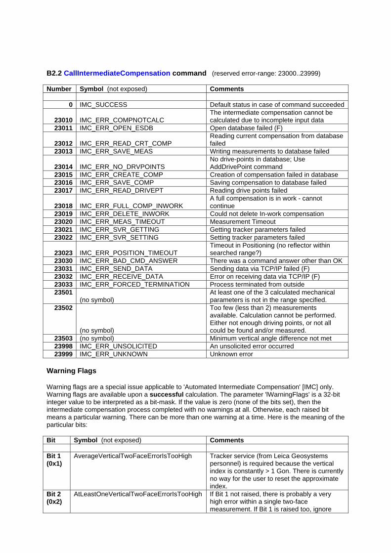
B2.2 CallIntermediateCompensation command (reserved error-range: 23000..23999) Number Symbol (not exposed) Comments
0 IMC_SUCCESS Default status in case of command succeeded
23010 IMC_ERR_COMPNOTCALC The intermediate compensation cannot be calculated due to incomplete input data
23011 IMC_ERR_OPEN_ESDB Open database failed (F)
23012 IMC_ERR_READ_CRT_COMP Reading current compensation from database failed
23013 IMC_ERR_SAVE_MEAS Writing measurements to database failed
23014 IMC_ERR_NO_DRVPOINTS No drive-points in database; Use AddDrivePoint command
23015 IMC_ERR_CREATE_COMP Creation of compensation failed in database 23016 IMC_ERR_SAVE_COMP Saving compensation to database failed 23017 IMC_ERR_READ_DRIVEPT Reading drive points failed
23018 IMC_ERR_FULL_COMP_INWORK A full compensation is in work - cannot continue
23019 IMC_ERR_DELETE_INWORK Could not delete In-work compensation 23020 IMC_ERR_MEAS_TIMEOUT Measurement Timeout 23021 IMC_ERR_SVR_GETTING Getting tracker parameters failed 23022 IMC_ERR_SVR_SETTING Setting tracker parameters failed
23023 IMC_ERR_POSITION_TIMEOUT Timeout in Positioning (no reflector within searched range?)
23030 IMC_ERR_BAD_CMD_ANSWER There was a command answer other than OK 23031 IMC_ERR_SEND_DATA Sending data via TCP/IP failed (F) 23032 IMC_ERR_RECEIVE_DATA Error on receiving data via TCP/IP (F) 23033 IMC_ERR_FORCED_TERMINATION Process terminated from outside 23501
(no symbol) At least one of the 3 calculated mechanical parameters is not in the range specified.
23502
(no symbol)
Too few (less than 2) measurements available. Calculation cannot be performed. Either not enough driving points, or not all could be found and/or measured.
23503 (no symbol) Minimum vertical angle difference not met 23998 IMC_ERR_UNSOLICITED An unsolicited error occurred 23999 IMC_ERR_UNKNOWN Unknown error
Warning Flags Warning flags are a special issue applicable to 'Automated Intermediate Compensation' [IMC] only. Warning flags are available upon a successful calculation. The parameter 'lWarningFlags' is a 32-bit integer value to be interpreted as a bit-mask. If the value is zero (none of the bits set), then the intermediate compensation process completed with no warnings at all. Otherwise, each raised bit means a particular warning. There can be more than one warning at a time. Here is the meaning of the particular bits: Bit Symbol (not exposed) Comments Bit 1 (0x1)
AverageVerticalTwoFaceErrorIsTooHigh Tracker service (from Leica Geosystems personnel) is required because the vertical index is constantly > 1 Gon. There is currently no way for the user to reset the approximate index.
Bit 2 (0x2)
AtLeastOneVerticalTwoFaceErrorIsTooHigh If Bit 1 not raised, there is probably a very high error within a single two-face measurement. If Bit 1 is raised too, ignore
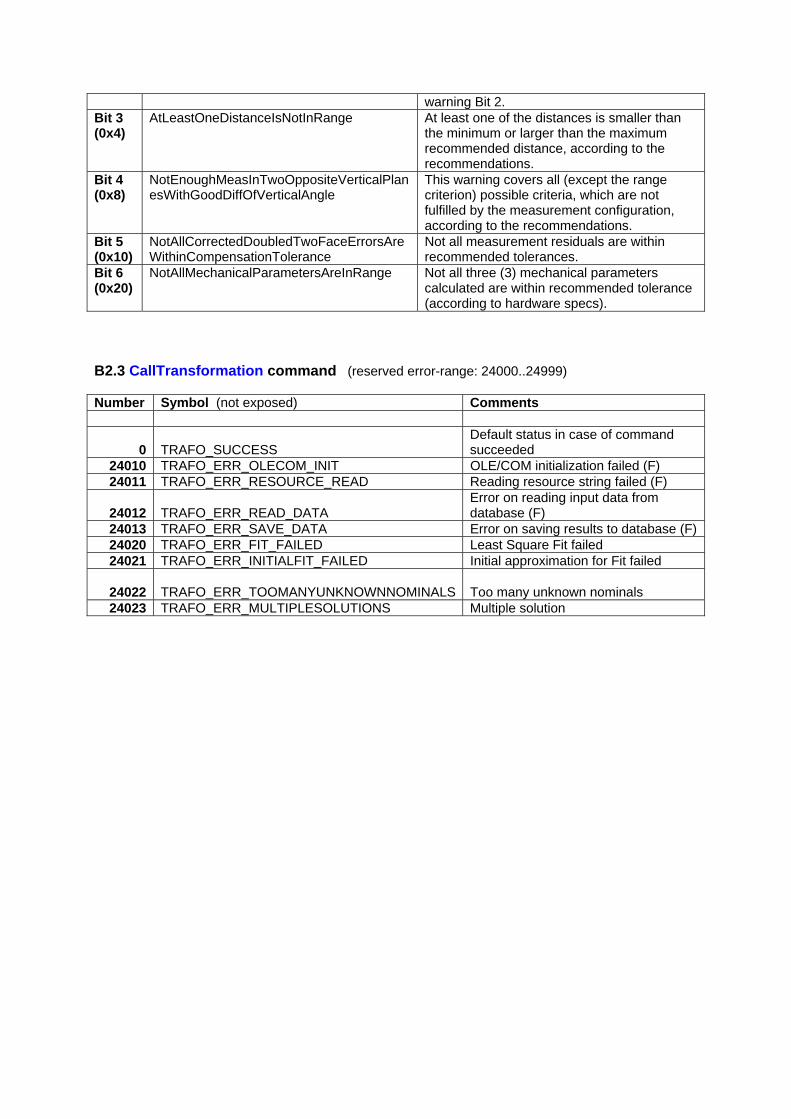
warning Bit 2. Bit 3 (0x4)
AtLeastOneDistanceIsNotInRange At least one of the distances is smaller than the minimum or larger than the maximum recommended distance, according to the recommendations.
Bit 4 (0x8)
NotEnoughMeasInTwoOppositeVerticalPlanesWithGoodDiffOfVerticalAngle
This warning covers all (except the range criterion) possible criteria, which are not fulfilled by the measurement configuration, according to the recommendations.
Bit 5 (0x10)
NotAllCorrectedDoubledTwoFaceErrorsAreWithinCompensationTolerance
Not all measurement residuals are within recommended tolerances.
Bit 6 (0x20)
NotAllMechanicalParametersAreInRange Not all three (3) mechanical parameters calculated are within recommended tolerance (according to hardware specs).
B2.3 CallTransformation command (reserved error-range: 24000..24999) Number Symbol (not exposed) Comments
0 TRAFO_SUCCESS Default status in case of command succeeded
24010 TRAFO_ERR_OLECOM_INIT OLE/COM initialization failed (F) 24011 TRAFO_ERR_RESOURCE_READ Reading resource string failed (F)
24012 TRAFO_ERR_READ_DATA Error on reading input data from database (F)
24013 TRAFO_ERR_SAVE_DATA Error on saving results to database (F) 24020 TRAFO_ERR_FIT_FAILED Least Square Fit failed 24021 TRAFO_ERR_INITIALFIT_FAILED Initial approximation for Fit failed
24022 TRAFO_ERR_TOOMANYUNKNOWNNOMINALS Too many unknown nominals
24023 TRAFO_ERR_MULTIPLESOLUTIONS Multiple solution
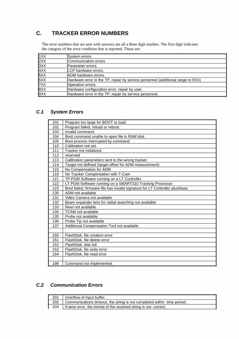
C. TRACKER ERROR NUMBERS
The error numbers that are sent with answers are all a three digit number. The first digit indicates the category of the error condition that is reported. These are:
1XX System errors. 2XX Communication errors 3XX Parameter errors. 4XX LCP hardware errors. 5XX ADM hardware errors. 6XX Hardware error in the TP, repair by service personnel (additional range to 9XX) 7XX Operation errors. 8XX Hardware configuration error, repair by user. 9XX Hardware error in the TP, repair by service personnel.
C.1 System Errors 101 Program too large for BOOT to load. 102 Program failed, reload or reboot. 103 Invalid command. 104 Boot command unable to open file in RAM disk 105 Boot process interrupted by command 110 Calibration not set. 111 Tracker not initialized. 112 reserved 113 Calibration parameters sent to the wrong tracker. 114 Target not defined (target offset for ADM measurement) 115 No Compensation for ADM 116 No Tracker Compensation with T-Cam 121 TP.PGM Software running on a LT Controller 122 LT.PGM Software running on a SMART310 Tracking Processor 123 Boot failed, firmware file has invalid signature for LT Controller plus/base 130 ADM not available 131 Video Camera not available 132 Beam expander lens for radial searching not available 133 Nivel not available 134 TCAM not available 135 Probe not available 136 Probe Tip not available 137 Additional Compensation Tool not available 150 FlashDisk, file creation error 151 FlashDisk, file delete error 152 FlashDisk, disk full 153 FlashDisk, file write error 154 FlashDisk, file read error 199 Command not implemented.
C.2 Communication Errors 201 Overflow of input buffer. 202 Communications timeout, the string is not completed within time period. 203 Frame error, the format of the received string is not correct.
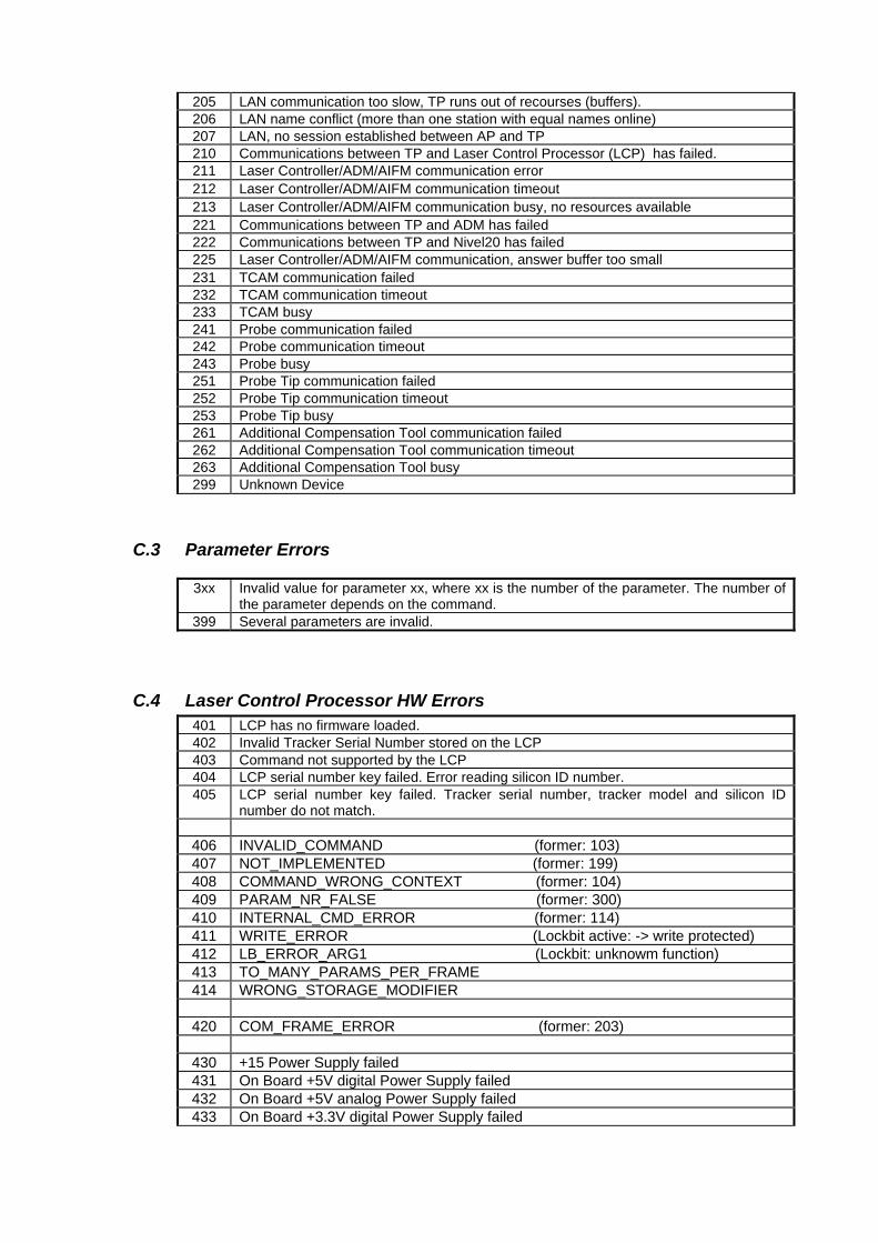
205 LAN communication too slow, TP runs out of recourses (buffers). 206 LAN name conflict (more than one station with equal names online) 207 LAN, no session established between AP and TP 210 Communications between TP and Laser Control Processor (LCP) has failed.
211 Laser Controller/ADM/AIFM communication error 212 Laser Controller/ADM/AIFM communication timeout 213 Laser Controller/ADM/AIFM communication busy, no resources available
221 Communications between TP and ADM has failed 222 Communications between TP and Nivel20 has failed
225 Laser Controller/ADM/AIFM communication, answer buffer too small 231 TCAM communication failed 232 TCAM communication timeout 233 TCAM busy 241 Probe communication failed 242 Probe communication timeout 243 Probe busy 251 Probe Tip communication failed 252 Probe Tip communication timeout 253 Probe Tip busy 261 Additional Compensation Tool communication failed 262 Additional Compensation Tool communication timeout 263 Additional Compensation Tool busy
299 Unknown Device
C.3 Parameter Errors 3xx Invalid value for parameter xx, where xx is the number of the parameter. The number of
the parameter depends on the command. 399 Several parameters are invalid.
C.4 Laser Control Processor HW Errors 401 LCP has no firmware loaded. 402 Invalid Tracker Serial Number stored on the LCP 403 Command not supported by the LCP 404 LCP serial number key failed. Error reading silicon ID number. 405 LCP serial number key failed. Tracker serial number, tracker model and silicon ID
number do not match. 406 INVALID_COMMAND (former: 103) 407 NOT_IMPLEMENTED (former: 199) 408 COMMAND_WRONG_CONTEXT (former: 104) 409 PARAM_NR_FALSE (former: 300) 410 INTERNAL_CMD_ERROR (former: 114) 411 WRITE_ERROR (Lockbit active: -> write protected) 412 LB_ERROR_ARG1 (Lockbit: unknowm function) 413 TO_MANY_PARAMS_PER_FRAME 414 WRONG_STORAGE_MODIFIER 420 COM_FRAME_ERROR (former: 203) 430 +15 Power Supply failed 431 On Board +5V digital Power Supply failed 432 On Board +5V analog Power Supply failed 433 On Board +3.3V digital Power Supply failed

434 On Board +4.096V reference Voltage failed 435 Peltier Check failed 436 Single Fault Diode cable not connected 437 Peltier cable not connected 438 Laser Power Supply cable not connected 439 Laser Temperature Sensor is not working 440 Air in Temperature Sensor is not working 441 Heatsink Temperature Sensor is not working 442 Air out Temperature Sensor is not working 449 Unknown hardware error 460 Laser current failed 461 Laser Off-Spike detected 462 Laser Mode Light failed, not enough light 463 Polarisation error to high 464 No minimum light value detected 465 Laser Mode Hopping -> Warmup changed to Temperature Mode 480 TIMEOUT: Laser Modecounting failed 481 TIMEOUT: Laser unable to stabilize 485 TIMEOUT: Looptimer stopped, -> Watchdog 499 Unknown error
C.5 Absolute Distance Meter HW Errors 501 ADM has no firmware loaded. 502 Set frequency not locked. 503 Set frequency, illegal state (internal software error) 504 Measurement cycles exceeded 505 Reserved 506 Illegal state (internal software error) 507 Minimum lost, unstable measurement conditions 508 Reserved 509 Start failed, hardware error 510 Reserved 511 Band scanning failed 512 Frequency unstable 513 No RF current 514 Frequency current error 515 Security timeout, maximal measurement time exceeded 516 Security lock, no light from Interferometer 517 Invalid distance 518 Emergency Power Output Lock, 519 Measurement aborted by user/Application ... 550 Light polarization during ADM measurement too unstable
(happens normally only on large entry angles into prisms) 551 ADM measurement, distance difference of double measurement out of tolerance 552 ADM measurement, invalid temperature
... 597 ADM communication, frame error 598 ADM –LTC communication, internal software error 599 unknown ADM error
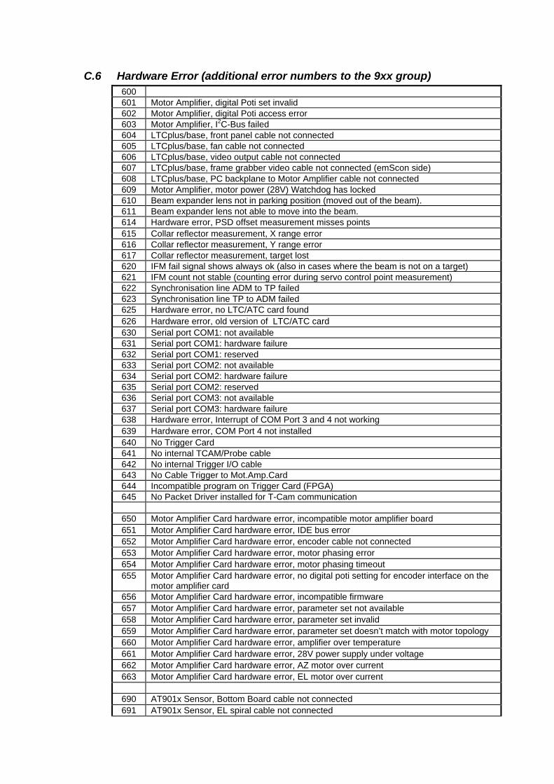
C.6 Hardware Error (additional error numbers to the 9xx group) 600 601 Motor Amplifier, digital Poti set invalid 602 Motor Amplifier, digital Poti access error 603 Motor Amplifier, I2C-Bus failed 604 LTCplus/base, front panel cable not connected 605 LTCplus/base, fan cable not connected 606 LTCplus/base, video output cable not connected 607 LTCplus/base, frame grabber video cable not connected (emScon side) 608 LTCplus/base, PC backplane to Motor Amplifier cable not connected 609 Motor Amplifier, motor power (28V) Watchdog has locked 610 Beam expander lens not in parking position (moved out of the beam). 611 Beam expander lens not able to move into the beam.
614 Hardware error, PSD offset measurement misses points 615 Collar reflector measurement, X range error 616 Collar reflector measurement, Y range error 617 Collar reflector measurement, target lost 620 IFM fail signal shows always ok (also in cases where the beam is not on a target) 621 IFM count not stable (counting error during servo control point measurement) 622 Synchronisation line ADM to TP failed 623 Synchronisation line TP to ADM failed
625 Hardware error, no LTC/ATC card found 626 Hardware error, old version of LTC/ATC card
630 Serial port COM1: not available 631 Serial port COM1: hardware failure 632 Serial port COM1: reserved 633 Serial port COM2: not available 634 Serial port COM2: hardware failure 635 Serial port COM2: reserved 636 Serial port COM3: not available 637 Serial port COM3: hardware failure
638 Hardware error, Interrupt of COM Port 3 and 4 not working 639 Hardware error, COM Port 4 not installed
640 No Trigger Card 641 No internal TCAM/Probe cable 642 No internal Trigger I/O cable 643 No Cable Trigger to Mot.Amp.Card 644 Incompatible program on Trigger Card (FPGA) 645 No Packet Driver installed for T-Cam communication
650 Motor Amplifier Card hardware error, incompatible motor amplifier board 651 Motor Amplifier Card hardware error, IDE bus error 652 Motor Amplifier Card hardware error, encoder cable not connected 653 Motor Amplifier Card hardware error, motor phasing error 654 Motor Amplifier Card hardware error, motor phasing timeout 655 Motor Amplifier Card hardware error, no digital poti setting for encoder interface on the
motor amplifier card 656 Motor Amplifier Card hardware error, incompatible firmware 657 Motor Amplifier Card hardware error, parameter set not available 658 Motor Amplifier Card hardware error, parameter set invalid 659 Motor Amplifier Card hardware error, parameter set doesn’t match with motor topology 660 Motor Amplifier Card hardware error, amplifier over temperature 661 Motor Amplifier Card hardware error, 28V power supply under voltage 662 Motor Amplifier Card hardware error, AZ motor over current 663 Motor Amplifier Card hardware error, EL motor over current
690 AT901x Sensor, Bottom Board cable not connected 691 AT901x Sensor, EL spiral cable not connected
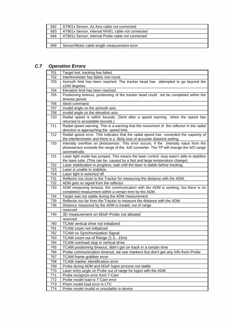
692 AT901x Sensor, Az Axis cable not connected 693 AT901x Sensor, internal NIVEL cable not connected 694 AT901x Sensor, internal Probe cable not connected 699 Sensor/Motor cable length measurement error
C.7 Operation Errors 701 Target lost, tracking has failed. 702 Interferometer has failed, lost count. 703 Azimuth limit has been reached. The tracker head has attempted to go beyond the
±240 degrees. 704 Elevation limit has been reached. 705 Positioning timeout, positioning of the tracker head could not be completed within the
timeout period. 706 Abort command. 707 invalid angle on the azimuth axis. 708 invalid angle on the elevation axis. 710 Radial speed is within bounds. (Sent after a speed warning when the speed has
returned to acceptable bounds.) 711 Radial speed warning. This is a warning that the movement of the reflector in the radial
direction is approaching the speed limit. 712 Radial speed error. This indicates that the radial speed has exceeded the capacity of
the interferometer and there is a likely loss of accurate distance setting. 720 Intensity overflow on photosensor. This error occurs, if the intensity value from the
photosensor exceeds the range of the A/D converter. The TP will change the A/D range automatically.
721 Laser light mode has jumped. This means the laser control loop wasn’t able to stabilize the laser tube. (This can be caused by a fast and large temperature change).
722 Laser stabilization in progress, wait until the laser is stable before tracking. 723 Laser is unable to stabilize. 724 Laser light is switched off. 731 Reflector too close to the Tracker for measuring the distance with the ADM. 732 ADM gets no signal from the reflector 733 ADM measuring timeout, the communication with the ADM is working, but there is no
completed measurment within a certain time by the ADM. 734 Target was not stable during the ADM measurement 735 Reflector too far from the Tracker to measure the distance with the ADM. 736 Distance measured by the ADM is invalid, out of range reserved 740 3D measurement on 6DoF-Probe not allowed reserved 760 TCAM vertical drive not initialized 761 TCAM zoom not initialized 762 TCAM no Synchronization Signal 763 TCAM zoom out of Range (1.5...15m) 764 TCAM overload stop in vertical drive 765 TCAM positioning timeout, didn’t get on track in a certain time 766 Probe communication timeout, we see markers but don’t get any Info from Probe 767 TCAM frame grabber error 768 TCAM marker identification error 769 Probe during ADM and 6DoF logon process not stable 770 Laser entry angle on Probe out of range for logon with the ADM 771 Probe recognize error from T-Cam 772 Probe model load to T-Cam error 773 Prism model load error in LTC 774 Probe model invalid or unsuitable to device
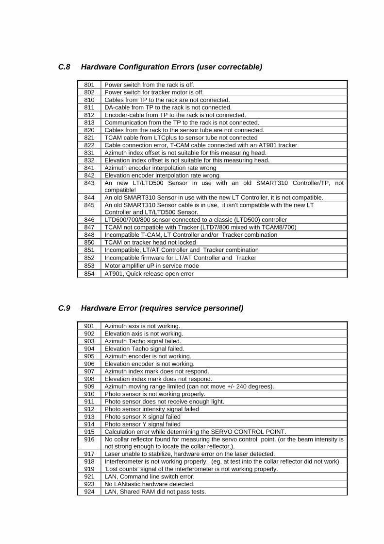
C.8 Hardware Configuration Errors (user correctable) 801 Power switch from the rack is off. 802 Power switch for tracker motor is off. 810 Cables from TP to the rack are not connected. 811 DA-cable from TP to the rack is not connected. 812 Encoder-cable from TP to the rack is not connected. 813 Communication from the TP to the rack is not connected. 820 Cables from the rack to the sensor tube are not connected. 821 TCAM cable from LTCplus to sensor tube not connected 822 Cable connection error, T-CAM cable connected with an AT901 tracker 831 Azimuth index offset is not suitable for this measuring head. 832 Elevation index offset is not suitable for this measuring head. 841 Azimuth encoder interpolation rate wrong 842 Elevation encoder interpolation rate wrong 843 An new LT/LTD500 Sensor in use with an old SMART310 Controller/TP, not
compatible! 844 An old SMART310 Sensor in use with the new LT Controller, it is not compatible. 845 An old SMART310 Sensor cable is in use, it isn’t compatible with the new LT
Controller and LT/LTD500 Sensor. 846 LTD600/700/800 sensor connected to a classic (LTD500) controller 847 TCAM not compatible with Tracker (LTD7/800 mixed with TCAM8/700) 848 Incompatible T-CAM, LT Controller and/or Tracker combination 850 TCAM on tracker head not locked
851 Incompatible, LT/AT Controller and Tracker combination 852 Incompatible firmware for LT/AT Controller and Tracker 853 Motor amplifier uP in service mode 854 AT901, Quick release open error
C.9 Hardware Error (requires service personnel) 901 Azimuth axis is not working. 902 Elevation axis is not working. 903 Azimuth Tacho signal failed. 904 Elevation Tacho signal failed. 905 Azimuth encoder is not working. 906 Elevation encoder is not working. 907 Azimuth index mark does not respond. 908 Elevation index mark does not respond. 909 Azimuth moving range limited (can not move +/- 240 degrees). 910 Photo sensor is not working properly. 911 Photo sensor does not receive enough light. 912 Photo sensor intensity signal failed 913 Photo sensor X signal failed 914 Photo sensor Y signal failed 915 Calculation error while determining the SERVO CONTROL POINT. 916 No collar reflector found for measuring the servo control point. (or the beam intensity is
not strong enough to locate the collar reflector.). 917 Laser unable to stabilize, hardware error on the laser detected. 918 Interferometer is not working properly. (eg, at test into the collar reflector did not work) 919 ‘Lost counts’ signal of the interferometer is not working properly. 921 LAN, Command line switch error. 923 No LANtastic hardware detected. 924 LAN, Shared RAM did not pass tests.
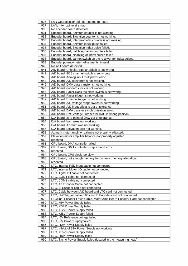
925 LAN Coprocessor did not respond to reset. 927 LAN, Interrupt level error. 930 No encoder board detected. 931 Encoder board, Azimuth counter is not working. 932 Encoder board, Elevation counter is not working. 933 Encoder board, Interferometer counter is not working. 934 Encoder board, Azimuth index pulse failed. 935 Encoder board, Elevation index pulse failed. 936 Encoder board, Latch signal for counters failed. 937 Encoder board, disabling of index pulses failed. 938 Encoder board, cannot switch on the receiver for index pulses. 939 Encoder potentiometer adjustments, invalid. 940 No A/D board detected. 941 A/D board, Unipolar/Bipolar switch is set wrong. 942 A/D board, 8/16 channel switch is set wrong. 943 A/D board, Analog input multiplexor error. 944 A/D board, A/D converter is not working. 945 A/D board, DMA data transfer is not working. 946 A/D board, onboard clock is not working. 947 A/D board, Pacer clock too slow, switch is set wrong. 948 A/D board, Pacer trigger is not working. 949 A/D board, External trigger is not working. 950 A/D board, A/D voltage range switch is not working. 951 A/D board, A/D input offset is out of tolerance. 952 A/D board, DMA transfer synchronization error. 953 A/D board, Ref. Voltage Jumper for DAC in wrong position 954 D/A board, zero point of DAC out of tolerance 955 D/A board, both axes not working. 956 D/A board, Azimuth axis not working. 957 D/A board, Elevation axis not working. 958 Azimuth motor amplifier balance not properly adjusted. 959 Elevation motor amplifier balance not properly adjusted. 960 reserved 961 CPU board, DMA controller failed. 962 CPU board, DMA controller wrap around error 963 reserved 964 CPU board, CPU clock too slow. 968 CPU board, not enough memory for dynamic memory allocation. 969 reserved 970 LTC, internal PSD input cable not connected. 971 LTC, internal Motor I/O cable not connected. 972 LTC Digital I/O cable not connected. 973 LTC, COM1 cable not connected 974 LTC, COM2 cable not connected 975 LTC, Az Encoder Cable not connected 976 LTC, El Encoder cable not connected 977 LTC, Cable between A/D board and LTC card not connected 978 LTC, HW Trigger cable LTC card to Encoder card not connected 979 LTCplus, Encoder Latch Cable, Motor Amplifier to Encoder Card not connected 980 LTC, +5V Power Supply failed 981 LTC, +7V Power Supply failed 982 LTC, +12V Power Supply failed 983 LTC, +28V Power Supply failed 984 LTC, -5V Reference voltage failed 985 LTC, -7V Power Supply failed 986 LTC, -12V Power Supply failed 987 LTC, Inhibit of 28V Power Supply not working 988 LTC, +15V Power Supply failed 989 LTC, -15V Power Supply failed 990 LTC, Tacho Power Supply failed (located in the measuring head)

991 LTC, 2.5/3.3V Supply failed on LTC Card 992 LTCplus, +5V Supply failed on Motor Amplifier 993 LTCplus, +12V Supply failed on Motor Amplifier 994 LTCplus, -12V Supply failed on Motor Amplifier 995 LTCplus, +3.3V Supply failed on Tracker Server (emScon) 996 LTCplus, +12V Supply failed on Tracker Server (emScon) 997 LTCplus, -12V Supply failed on Tracker Server (emScon) 998 LTCplus, Power for FAN’s on Front Panel failed 999 Unknown hardware error.
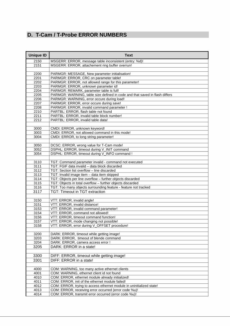
D. T-Cam / T-Probe ERROR NUMBERS Unique ID Text
2150 MSGERR: ERROR, message table inconsistent (entry: %d)! 2151 MSGERR: ERROR, attachement ring buffer overrun!
2200 PARMGR: MESSAGE, New parameter initialisation! 2201 PARMGR: ERROR, CRC on parameter table! 2202 PARMGR: ERROR, not allowed range for this parameter! 2203 PARMGR: ERROR, unknown parameter id! 2204 PARMGR: REMARK, parameter table is full! 2205 PARMGR: WARNING, table size defined in code and that saved in flash differs 2206 PARMGR: WARNING, error occure during load! 2207 PARMGR: ERROR, error occure during save! 2208 PARMGR: ERROR, invalid command parameter ! 2210 PARTBL: ERROR, flash table not found 2211 PARTBL: ERROR, invalid table block number! 2212 PARTBL: ERROR, invalid table data!
3000 CMDI: ERROR, unknown keyword! 3003 CMDI: ERROR, not allowed command in this mode! 3004 CMDI: ERROR, to long string parameter!
3050 DCSC: ERROR, wrong value for T-Cam mode! 3052 DSPHL: ERROR, timeout during V_INIT command 3054 DSPHL: ERROR, timeout during V_INFO command !
3110 TGT: Command parameter invalid - command not executed 3111 TGT: FGIF data invalid – data block discarded 3112 TGT: Section list overflow – line discarded 3113 TGT: Invalid image item – data item skipped 3114 TGT: Objects per line overflow – further objects discarded 3115 TGT: Objects in total overflow – further objects discarded 3116 TGT: Too many objects surrounding feature - feature not tracked 3117 TGT: Timeout in TGT extraction
3150 VTT: ERROR, invalid angle! 3151 VTT: ERROR, invalid distance! 3153 VTT: ERROR, invalid command parameter! 3154 VTT: ERROR, command not allowed! 3156 VTT: ERROR, timeout command function! 3157 VTT: ERROR, mode changing not possible! 3158 VTT: ERROR, error during V_OFFSET procedure!
3200 DARK: ERROR, timeout while getting image! 3203 DARK: ERROR, timeout of blende command 3204 DARK: ERROR, camera access error ! 3205 DARK: ERROR in a state!
3300 DIFF: ERROR, timeout while getting image! 3301 DIFF: ERROR in a state!
4000 COM: WARNING, too many active ethernet clients 4001 COM: WARNING, ethernet client id not found 4010 COM: ERROR, ethernet module already initialized! 4011 COM: ERROR, init of the ethernet module failed! 4012 COM: ERROR, trying to access ethernet module in uninitialized state! 4013 COM: ERROR, receiving error occurred (error code %u)! 4014 COM: ERROR, transmit error occurred (error code %u)!
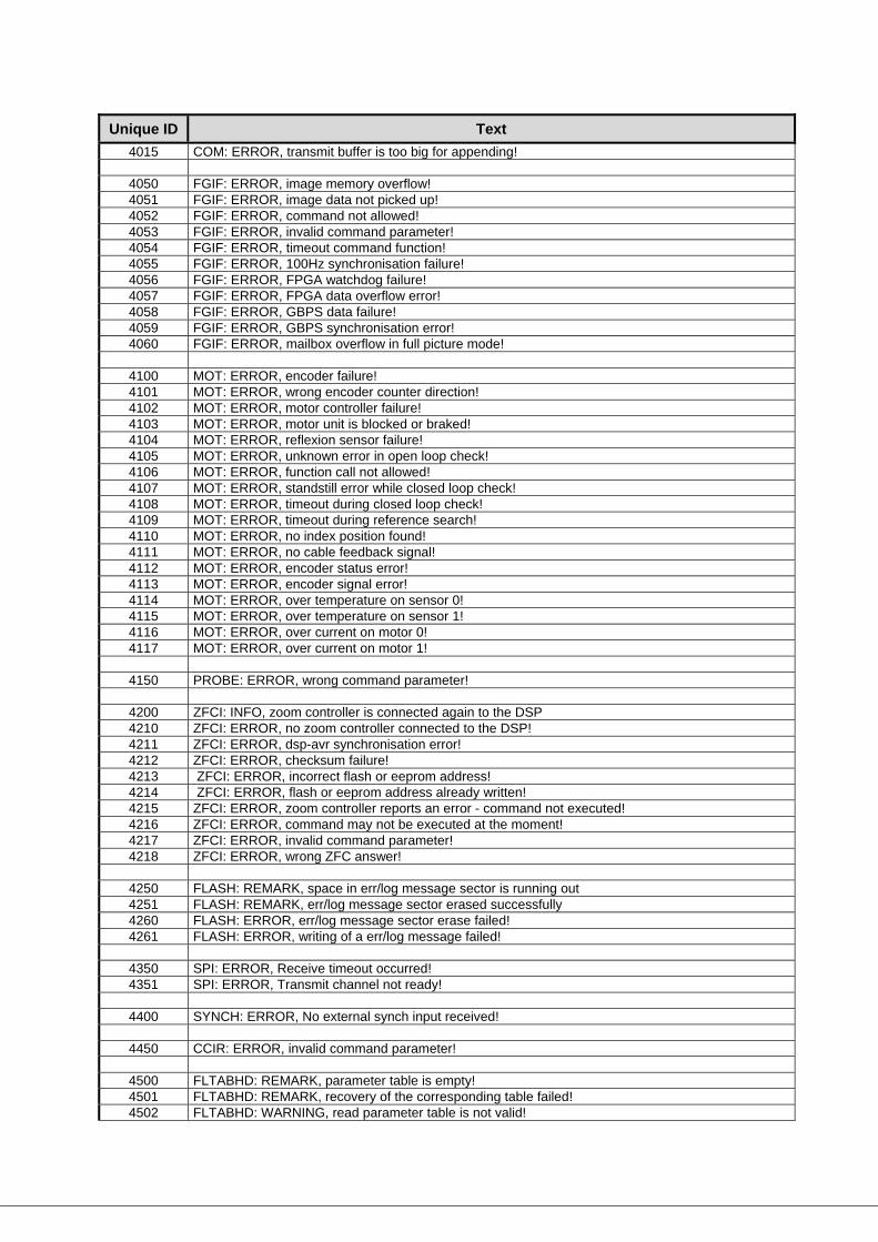
Unique ID Text 4015 COM: ERROR, transmit buffer is too big for appending!
4050 FGIF: ERROR, image memory overflow! 4051 FGIF: ERROR, image data not picked up! 4052 FGIF: ERROR, command not allowed! 4053 FGIF: ERROR, invalid command parameter! 4054 FGIF: ERROR, timeout command function! 4055 FGIF: ERROR, 100Hz synchronisation failure! 4056 FGIF: ERROR, FPGA watchdog failure! 4057 FGIF: ERROR, FPGA data overflow error! 4058 FGIF: ERROR, GBPS data failure! 4059 FGIF: ERROR, GBPS synchronisation error! 4060 FGIF: ERROR, mailbox overflow in full picture mode!
4100 MOT: ERROR, encoder failure! 4101 MOT: ERROR, wrong encoder counter direction! 4102 MOT: ERROR, motor controller failure! 4103 MOT: ERROR, motor unit is blocked or braked! 4104 MOT: ERROR, reflexion sensor failure! 4105 MOT: ERROR, unknown error in open loop check! 4106 MOT: ERROR, function call not allowed! 4107 MOT: ERROR, standstill error while closed loop check! 4108 MOT: ERROR, timeout during closed loop check! 4109 MOT: ERROR, timeout during reference search! 4110 MOT: ERROR, no index position found! 4111 MOT: ERROR, no cable feedback signal! 4112 MOT: ERROR, encoder status error! 4113 MOT: ERROR, encoder signal error! 4114 MOT: ERROR, over temperature on sensor 0! 4115 MOT: ERROR, over temperature on sensor 1! 4116 MOT: ERROR, over current on motor 0! 4117 MOT: ERROR, over current on motor 1!
4150 PROBE: ERROR, wrong command parameter!
4200 ZFCI: INFO, zoom controller is connected again to the DSP 4210 ZFCI: ERROR, no zoom controller connected to the DSP! 4211 ZFCI: ERROR, dsp-avr synchronisation error! 4212 ZFCI: ERROR, checksum failure! 4213 ZFCI: ERROR, incorrect flash or eeprom address! 4214 ZFCI: ERROR, flash or eeprom address already written! 4215 ZFCI: ERROR, zoom controller reports an error - command not executed! 4216 ZFCI: ERROR, command may not be executed at the moment! 4217 ZFCI: ERROR, invalid command parameter! 4218 ZFCI: ERROR, wrong ZFC answer!
4250 FLASH: REMARK, space in err/log message sector is running out 4251 FLASH: REMARK, err/log message sector erased successfully 4260 FLASH: ERROR, err/log message sector erase failed! 4261 FLASH: ERROR, writing of a err/log message failed!
4350 SPI: ERROR, Receive timeout occurred! 4351 SPI: ERROR, Transmit channel not ready!
4400 SYNCH: ERROR, No external synch input received!
4450 CCIR: ERROR, invalid command parameter!
4500 FLTABHD: REMARK, parameter table is empty! 4501 FLTABHD: REMARK, recovery of the corresponding table failed! 4502 FLTABHD: WARNING, read parameter table is not valid!
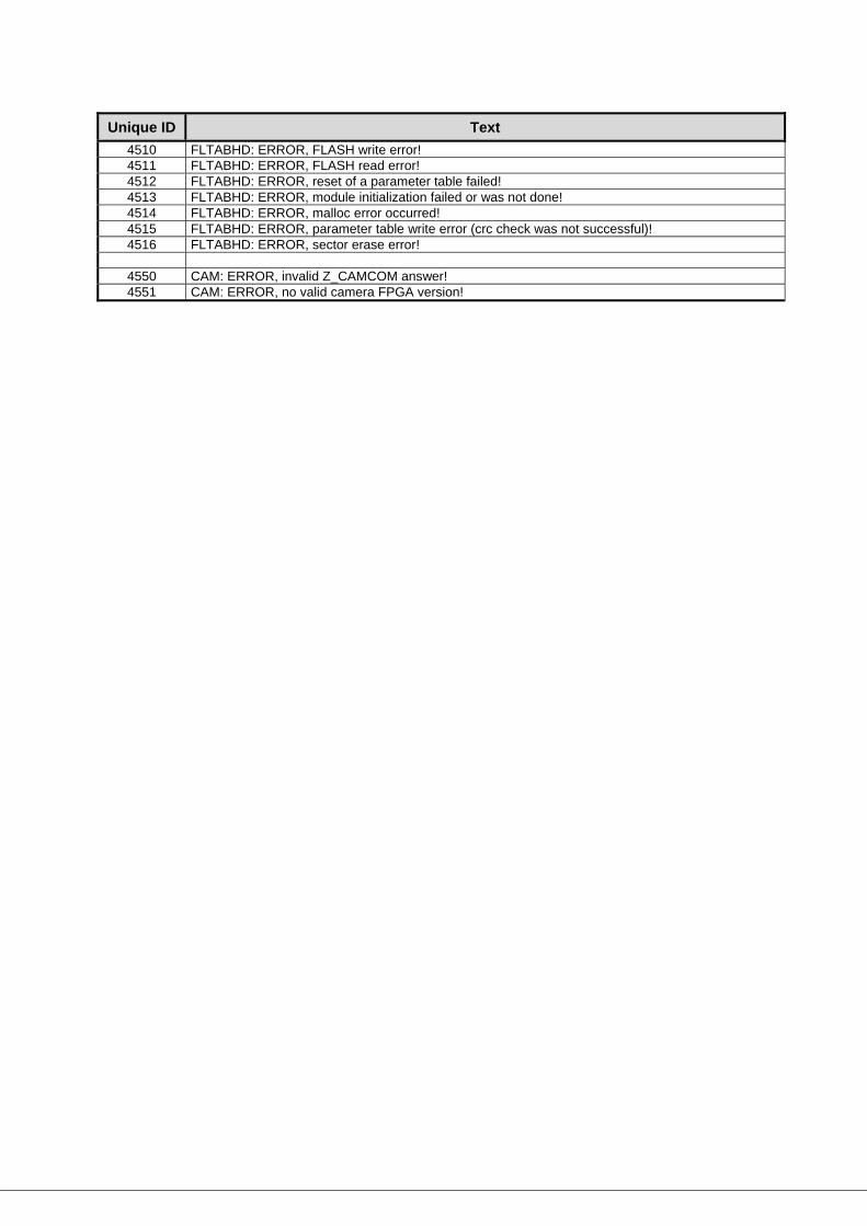
Unique ID Text 4510 FLTABHD: ERROR, FLASH write error! 4511 FLTABHD: ERROR, FLASH read error! 4512 FLTABHD: ERROR, reset of a parameter table failed! 4513 FLTABHD: ERROR, module initialization failed or was not done! 4514 FLTABHD: ERROR, malloc error occurred! 4515 FLTABHD: ERROR, parameter table write error (crc check was not successful)! 4516 FLTABHD: ERROR, sector erase error!
4550 CAM: ERROR, invalid Z_CAMCOM answer! 4551 CAM: ERROR, no valid camera FPGA version!
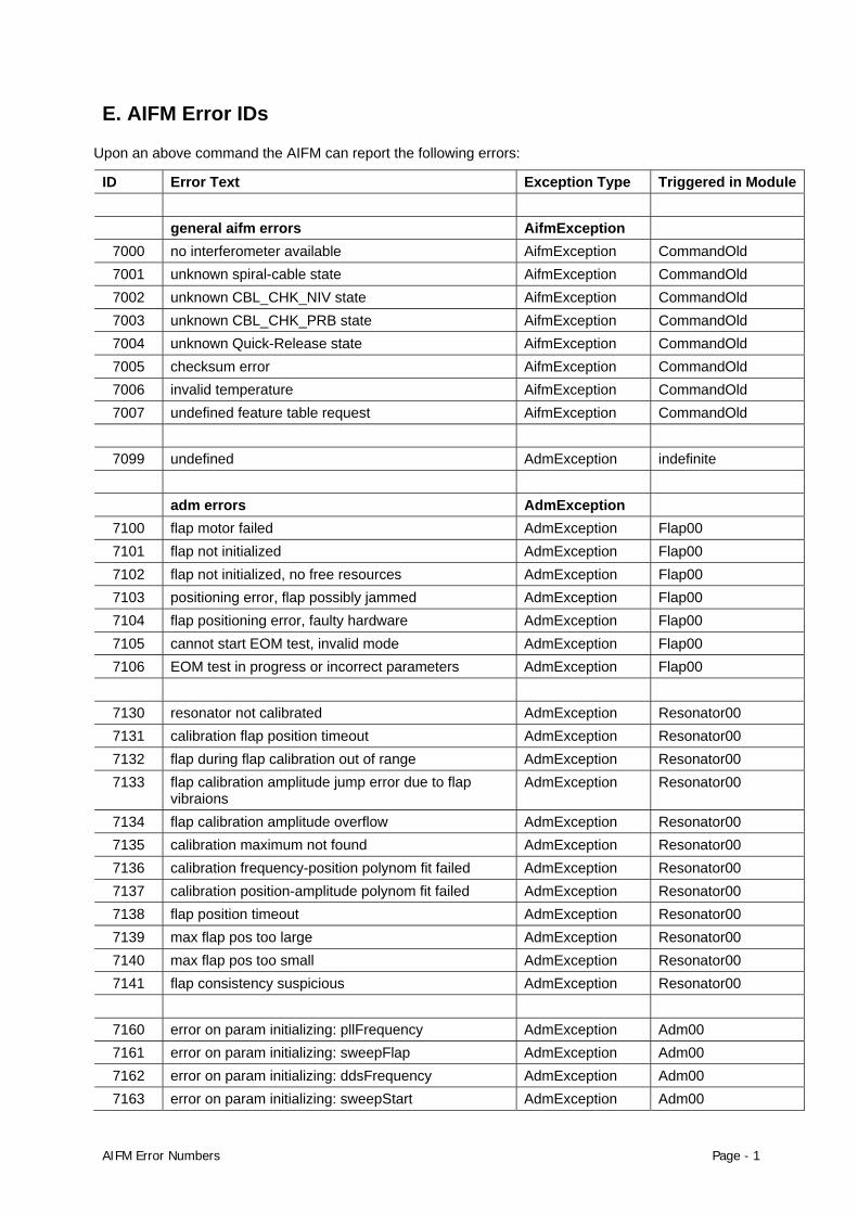
E. AIFM Error IDs Upon an above command the AIFM can report the following errors:
ID Error Text Exception Type Triggered in Module general aifm errors AifmException
7000 no interferometer available AifmException CommandOld 7001 unknown spiral-cable state AifmException CommandOld 7002 unknown CBL_CHK_NIV state AifmException CommandOld 7003 unknown CBL_CHK_PRB state AifmException CommandOld 7004 unknown Quick-Release state AifmException CommandOld 7005 checksum error AifmException CommandOld 7006 invalid temperature AifmException CommandOld 7007 undefined feature table request AifmException CommandOld
7099 undefined AdmException indefinite
adm errors AdmException
7100 flap motor failed AdmException Flap00 7101 flap not initialized AdmException Flap00 7102 flap not initialized, no free resources AdmException Flap00 7103 positioning error, flap possibly jammed AdmException Flap00 7104 flap positioning error, faulty hardware AdmException Flap00 7105 cannot start EOM test, invalid mode AdmException Flap00 7106 EOM test in progress or incorrect parameters AdmException Flap00
7130 resonator not calibrated AdmException Resonator00 7131 calibration flap position timeout AdmException Resonator00 7132 flap during flap calibration out of range AdmException Resonator00 7133 flap calibration amplitude jump error due to flap
vibraions AdmException Resonator00
7134 flap calibration amplitude overflow AdmException Resonator00 7135 calibration maximum not found AdmException Resonator00 7136 calibration frequency-position polynom fit failed AdmException Resonator00 7137 calibration position-amplitude polynom fit failed AdmException Resonator00 7138 flap position timeout AdmException Resonator00 7139 max flap pos too large AdmException Resonator00 7140 max flap pos too small AdmException Resonator00 7141 flap consistency suspicious AdmException Resonator00
7160 error on param initializing: pllFrequency AdmException Adm00 7161 error on param initializing: sweepFlap AdmException Adm00 7162 error on param initializing: ddsFrequency AdmException Adm00 7163 error on param initializing: sweepStart AdmException Adm00
AIFM Error Numbers Page - 1
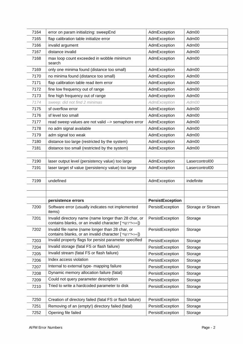
7164 error on param initializing: sweepEnd AdmException Adm00 7165 flap calibration table initialize error AdmException Adm00 7166 invalid argument AdmException Adm00 7167 distance invalid AdmException Adm00 7168 max loop count exceeded in wobble minimum
search AdmException Adm00
7169 only one minima found (distance too small) AdmException Adm00 7170 no minima found (distance too small) AdmException Adm00 7171 flap calibration table read item error AdmException Adm00 7172 fine low frequency out of range AdmException Adm00 7173 fine high frequency out of range AdmException Adm00 7174 sweep: did not find 2 minimas AdmException Adm00 7175 sf overflow error AdmException Adm00 7176 sf level too small AdmException Adm00 7177 read sweep values are not valid --> semaphore error AdmException Adm00 7178 no adm signal available AdmException Adm00 7179 adm signal too weak AdmException Adm00 7180 distance too large (restricted by the system) AdmException Adm00 7181 distance too small (restricted by the system) AdmException Adm00
7190 laser output level (persistency value) too large AdmException Lasercontrol00 7191 laser target sf value (persistency value) too large AdmException Lasercontrol00
7199 undefined AdmException indefinite
persistence errors PersistException
7200 Software error (usually indicates not implemented items)
PersistException Storage or Stream
7201 Invalid directory name (name longer than 28 char, or contains blanks, or an invalid character [`*\\|/:\"?<>=])
PersistException Storage
7202 Invalid file name (name longer than 28 char, or contains blanks, or an invalid character [`*\\|/:\"?<>=])
PersistException Storage
7203 Invalid property flags for persist parameter specified PersistException Storage 7204 Invalid storage (fatal FS or flash failure) PersistException Storage 7205 Invalid stream (fatal FS or flash failure) PersistException Storage 7206 Index access violation PersistException Storage 7207 Internal to external type- mapping failure PersistException Storage 7208 Dynamic memory allocation failure (fatal) PersistException Storage 7209 Could not query parameter description PersistException Storage 7210 Tried to write a hardcoded parameter to disk PersistException Storage
7250 Creation of directory failed (fatal FS or flash failure) PersistException Storage 7251 Removing of an (empty!) directory failed (fatal) PersistException Storage 7252 Opening file failed PersistException Storage
AIFM Error Numbers Page - 2
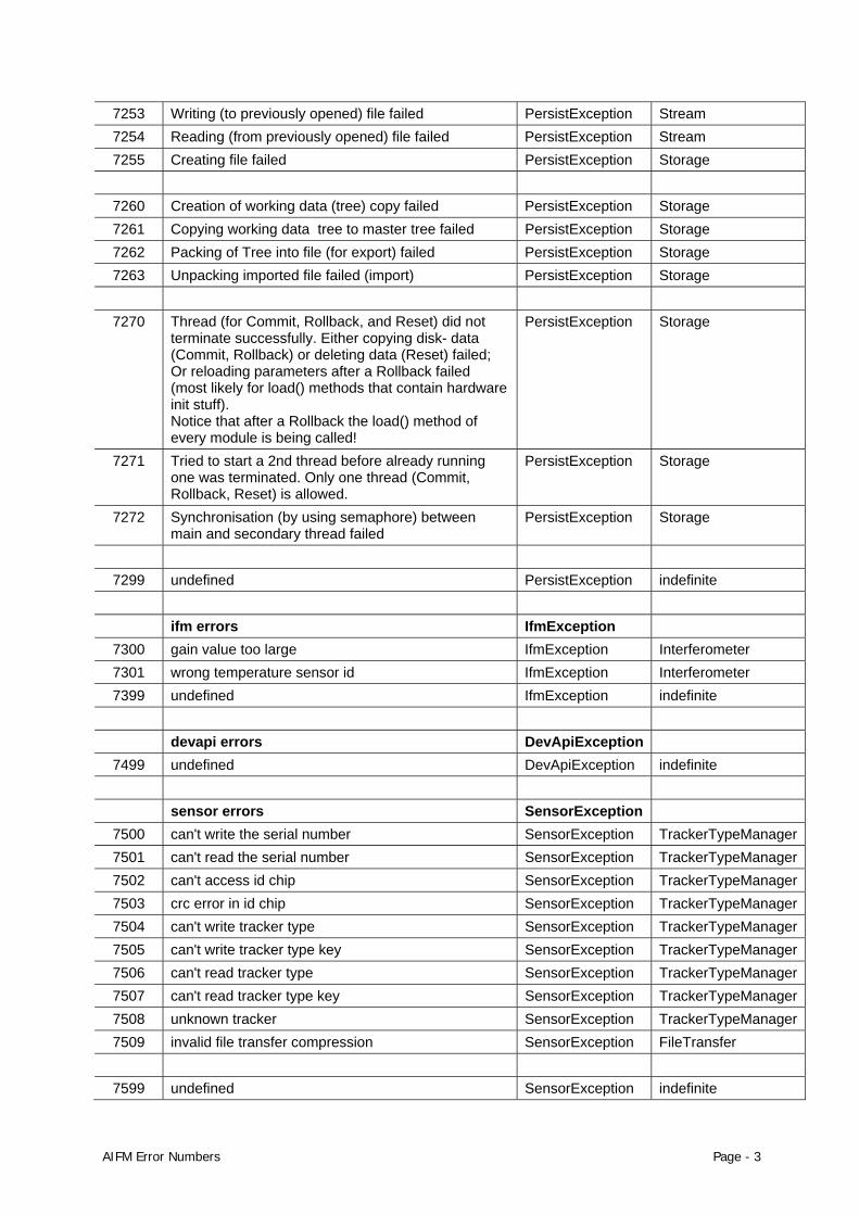
7253 Writing (to previously opened) file failed PersistException Stream 7254 Reading (from previously opened) file failed PersistException Stream 7255 Creating file failed PersistException Storage
7260 Creation of working data (tree) copy failed PersistException Storage 7261 Copying working data tree to master tree failed PersistException Storage 7262 Packing of Tree into file (for export) failed PersistException Storage 7263 Unpacking imported file failed (import) PersistException Storage
7270 Thread (for Commit, Rollback, and Reset) did not
terminate successfully. Either copying disk- data (Commit, Rollback) or deleting data (Reset) failed; Or reloading parameters after a Rollback failed (most likely for load() methods that contain hardware init stuff). Notice that after a Rollback the load() method of every module is being called!
PersistException Storage
7271 Tried to start a 2nd thread before already running one was terminated. Only one thread (Commit, Rollback, Reset) is allowed.
PersistException Storage
7272 Synchronisation (by using semaphore) between main and secondary thread failed
PersistException Storage
7299 undefined PersistException indefinite
ifm errors IfmException
7300 gain value too large IfmException Interferometer 7301 wrong temperature sensor id IfmException Interferometer 7399 undefined IfmException indefinite
devapi errors DevApiException
7499 undefined DevApiException indefinite sensor errors SensorException
7500 can't write the serial number SensorException TrackerTypeManager7501 can't read the serial number SensorException TrackerTypeManager7502 can't access id chip SensorException TrackerTypeManager7503 crc error in id chip SensorException TrackerTypeManager7504 can't write tracker type SensorException TrackerTypeManager7505 can't write tracker type key SensorException TrackerTypeManager7506 can't read tracker type SensorException TrackerTypeManager7507 can't read tracker type key SensorException TrackerTypeManager7508 unknown tracker SensorException TrackerTypeManager7509 invalid file transfer compression SensorException FileTransfer
7599 undefined SensorException indefinite
AIFM Error Numbers Page - 3

Whether building the fastest car, the biggest plane or the most precise tooling, you need exact measurements to improve quality and productivity. So when it has to be right, professionals trust Leica Geosystems metrology products to help collect, analyze and present 3-dimensional (3D) data for industrial measurement.
Leica Geosystems Metrology is best known for its broad array of control and industrial measurement products, including high-precision industrial theodolites and total stations, laser trackers and 6 Degrees of Freedom-based (6DOF) Portable CMM systems. The latter include the Leica T-Probe hand-held armless probe, Leica T-Scan hand-held laser scanner and Leica T-Mac tracking device for automated applications. Leica Geosystems also offers a broad range of 3D metrology software solutions. Those who use the metrology products by Leica Geosystems every day trust them for their dependability, the value they deliver and the world-class service and support that’s second to none.
Precision, reliability and service from Leica Geosystems metrology products.
When it has to be right.
©2008 Copyright Leica Geosystems AG, Heerbrugg, Switzerland. For more information, please contact [email protected]
Leica Geosystems AGMetrology ProductsMoenchmattweg 5CH-5035 UnterentfeldenSwitzerlandPhone +41 62 737 67 [email protected]
www.leica-geosystems.com/metrology


![Reference Guide MFC-J6947DW MFC-J6945DW MFC-J6545DW · MFC-J6545DW MFC-J6945DW MFC-J6947DW ... [Message from Brother] and [Firmware Auto Check] are set to [On]. (Internet connection](https://img.pdfslide.us/doc/110x75/5fe53fa6fe9ed37e6d21c94e/reference-guide-mfc-j6947dw-mfc-j6945dw-mfc-j6545dw-mfc-j6545dw-mfc-j6945dw-mfc-j6947dw.jpg)