Embed Size (px)
Citation preview

Programmers Manual – Tracker Programming Interface
emScon 2.1

Programmers Manual
emScon TPI
Metrology Division
1

Preface These are original instructions and part of the product. Keep for future reference and pass on to subsequent holder/user of product. Read instructions before setting-up and operating the hard- and software. The emScon TPI reference manual and the emScon TPI user manual should always be used together. This reference manual contains information protected by copyright and subject to change without notice. No part of this reference manual may be reproduced in any form without prior and written consent from Leica Geosystems AG. Leica Geosystems AG shall not be responsible for technical or editorial errors or omissions. Product names are trademarks or registered trademarks of their respective companies. The software described herein is furnished under license and non-disclosure agreement, and may be used only in accordance with the terms of the sales agreement. © Leica Geosystems AG Feedback Your feedback is important as we strive to improve the quality of our documentation. We request you to make specific comments as to where you envisage scope for improvement. Please use the following E-Mail address to send in suggestions: [email protected] Software and version emScon TPI; V2.1 Manual update April 2005 Manual order number None
2

Preface Contact Leica Geosystems AG Metrology Division Moenchmattweg 5 5035 Unterentfelden Switzerland Phone ++41 +62 737 67 67 Fax ++41 +62 737 68 34 www.leica-geosystems.com/ims/index.htm
3

1 Contents
1 Contents
2 Introduction2.1 Prerequisites..................................................8
2.1.1 Tracker Basics/Terminology ...............................8 2.1.2 Abbreviations......................................................8 2.1.3 Hardware ............................................................8 2.1.4 Programming Environment .................................9 2.1.5 TCP/IP Protocol..................................................9
2.2 TCP/IP Communication.................................9 2.2.1 Socket Functions ................................................9
2.3 Tracker Programming Interface .................11 2.3.1 Platform and Programming Language Issues 11 2.3.2 Prefixes and Suffixes used in Type Names ......12 2.3.3 Asynchronous Communication .........................13 2.3.4 Working Conditions...........................................14 2.3.5 Coordinate Parameter Triplets..........................16 2.3.6 Persistency .......................................................17 2.3.7 Default Settings ................................................17 2.3.8 Version Backward Compatibility ......................18 2.3.9 Sample Code....................................................20
2.4 Application Initial Steps..............................22 2.4.1 Essential Steps.................................................22 2.4.2 Command Sequence for 3D Measurements.....23 2.4.3 Command Sequence for 6DOF Measurements...............................................................25 2.4.4 Initial Steps Description in Detail ......................27
3 C - Interface3.1 Low-level TPI Programming .......................37
3.1.1 Preconditions....................................................37 3.1.2 Recommendation .............................................37 3.1.3 Byte Alignment .................................................38 3.1.4 Little/Big Endians..............................................38 3.1.5 Preprocessor Statements .................................39 3.1.6 TPI 'Boolean' Data Type ...................................39 3.1.7 Enumeration-Type Members Numerical representation................................................................40 3.1.8 Basic C Data Type size of TPI Structures.........40
3.2 Communication Basics...............................40 3.2.1 Commands .......................................................40 3.2.2 Command Answers ..........................................41 3.2.3 Error Events......................................................45
4

3.2.4 System Status Change Events .........................45 3.2.5 3D / 6 DOF – Related commands.....................46
3.3 C- Language TPI Reference........................47 3.3.1 Constants .........................................................47 3.3.2 Enumeration Types...........................................48
3.4 Data Structures..........................................133 3.4.1 Basic Data Structures.....................................133 3.4.2 Packet Data Structures...................................150
3.5 C - Language TPI Programming Instructions .........................................................205
3.5.1 TCP/IP Connection.........................................205 3.5.2 Sending Commands .......................................205 3.5.3 Initialization Macros ........................................206 3.5.4 Excurse: C++ Initialization ..............................207 3.5.5 Answers from Tracker Server .........................207 3.5.6 Asynchronous Communication .......................208 3.5.7 DataArrived Notification ..................................208 3.5.8 Data arrival 'Traffic Jams' ...............................208 3.5.9 PacketHeader Masking...................................209 3.5.10 Command Subtype Switch..........................210
3.6 C Language TPI - Samples .......................212 3.6.1 Sample 3 ........................................................212
4 C++ Interface4.1 Class- based TPI Programming ...............216
4.1.1 Preconditions..................................................216 4.1.2 Platform Issues...............................................217 4.1.3 TCP/IP ............................................................217
4.2 C++ Language TPI Reference...................217 4.2.1 CESAPICommand class.................................217 4.2.2 CESAPIReceive class ....................................219
4.3 C++ Language TPI Programming Instructions .........................................................221
4.3.1 Sending Data..................................................221 4.3.2 Receiving Data ...............................................221 4.3.3 Class Design Issues .......................................222 4.3.4 Data Structure Wrapper Classes ....................223 4.3.5 CESAPICommand..........................................224 4.3.6 CESAPIReceive..............................................226 4.3.7 Queued and Scattered Data ...........................227 4.3.8 Partial Settings Changes ................................231 4.3.9 Asynchronous Programming Issues ...............232
4.4 C++ Language TPI Samples .....................235 4.4.1 Sample 4 ........................................................235 4.4.2 Sample 9 ........................................................238 4.4.3 Sample 12 ......................................................239
5 COM - Interface5.1 High-level TPI Programming ....................242
5.1.1 Drawbacks......................................................242 5.1.2 Introduction.....................................................242
5.2 COM TPI Programming Instructions .......244 5.2.1 VisualBasic and VBA Applications..................244 5.2.2 C++ Applications ............................................247
5

5.2.3 Notification Method.........................................248 5.2.4 Exceptions and Return Types.........................250 5.2.5 COM TPI Programming Languages ..............253 5.2.6 Proper Interface Selection ..............................255 5.2.7 Type- Library ..................................................257 5.2.8 COM TPI Reference .......................................258 5.2.9 Registering COM Objects ...............................259 5.2.10 Synchronous versus Asynchronous Interface 260 5.2.11 Multi- Tracker Applications..........................261 5.2.12 Visual Basic Boolean variable evaluation....261 5.2.13 Reading Data Blocks with Visual Basic.......262 5.2.14 VBA Macro-Language Support ...................264 5.2.15 Continuous measurements and VBA ..........266 5.2.16 Scripting Language Support........................269 5.2.17 Exception Handling for Non- Microsoft Clients 269
5.3 COM TPI Samples......................................270 5.3.1 Sample 5 ........................................................270 5.3.2 Sample 7 ........................................................278 5.3.3 Sample 8 ........................................................285 5.3.4 Sample 14 ......................................................285 5.3.5 Sample 15 ......................................................286 5.3.6 Sample 18 ......................................................286 5.3.7 Sample 20 ......................................................286
6 C# - Interface6.1 Client Programming with C# ....................288
6.1.1 Introduction.....................................................288 6.1.2 C# Application Programming ..........................288 6.1.3 Sample 16 ......................................................289 6.1.4 Sample 17 ......................................................289
7 Base User Interface (BUI)7.1 Client Programming and BUI....................293
7.1.1 Measurement BUI versus Compensation Applications .................................................................293 7.1.2 EmScon Basic User Interface (BUI) ...............293 7.1.3 Integration of BUI into applications .................294 7.1.4 Sample 13 ......................................................294
8 Selected Commands in Detail 8.1 Special Functions......................................296
8.1.1 Get Reflectors Command ...............................296 8.1.2 Still Image Command .....................................300 8.1.3 Live Image display..........................................305 8.1.4 Orient To Gravity Procedure...........................310 8.1.5 Transformation Procedure ..............................311 8.1.6 Automated Intermediate Compensation .........313 8.1.7 Two Face Field-Check....................................317
9 Mathematics9.1 Point accuracy ...........................................322
6

9.1.1 A priori accuracy.............................................322 9.1.2 A posteriori accuracy ......................................323 9.1.3 Transformation of covariance matrices...........323
9.2 Orientation and Transformation ..............323 9.2.1 Orientation ......................................................324 9.2.2 Transformation ...............................................325 9.2.3 Nominal and actual coordinates .....................325 9.2.4 Orientation parameters ...................................326 9.2.5 Transformation parameters ............................327 9.2.6 Input to transformation computation ...............327 9.2.7 Output of transformation computation ............328 9.2.8 Examples........................................................330
9.3 T-Probe .......................................................332
10 Appendix A10.1 TRACKER ERROR NUMBERS ............334
10.1.1 System Errors .............................................334 10.1.2 Communication Errors ................................335 10.1.3 Parameter Errors ........................................335 10.1.4 Laser Control Processor HW Errors............335 10.1.5 Absolute Distance Meter HW Errors ...........335 10.1.6 Hardware Error (additional error numbers to the 9xx group)..........................................................336 10.1.7 Operation Errors .........................................336 10.1.8 Hardware Configuration Errors (user correctable)..................................................................337 10.1.9 Hardware Error (requires service personnel)....................................................................338
10.2 T- PRODUCTS ERROR NUMBERS .....339
7

2 Introduction
2.1 Prerequisites 2.1.1 Tracker Basics/Terminology This manual does not replace tracker operating knowledge. Users of this Reference Manual must be familiar with tracker operation and tracker-specific terms such as Bird bath, Tracker initialization etc. 2.1.2 Abbreviations TPI Tracker Programming
Interface TS Tracker Server CS Coordinate System ADM Absolute Distance Meter IFM Interferometer TP Tracker Processor NYI Not yet implemented LT Laser Tracker
2.1.3 Hardware The emScon TPI supports the following Laser Trackers:
• LT300
• LT500 & LTD500
• LT600 & LTD600
• LTD700
• LT800 & LTD800
8

2.1.4 Programming Environment This manual (notation, samples) is based on Microsoft Visual Studio 6.0 (VC++ 6.0, Visual Basic 6.0) running on Microsoft Windows (98/NT/2000). Some samples refer to VisualStudio 7.0 (C# and VB .NET samples)
• For Unicode applications, install VC++ with Unicode libraries (custom installation). Linker/runtime errors, such as: mfc42u.lib, mfc42ud.lib or mfc42u.dll missing, indicate that VC++ was installed without Unicode support.
2.1.5 TCP/IP Protocol Communication to the tracker server is based on TCP/IP. The client PC must be equipped with a TCP/IP-enabled LAN Board.
This manual does not cover hardware aninstallation issues.
d
2.2 TCP/IP Communication Communication with TCP/IP requires platform specific communication functions. These are not part of the emScon TPI and have to be provided, except when using the high-level TPI (COM interface).
The TCP/IP API functions of your operating system (OS) can be used. Keywords under VC++ include Win32 Sockets API, or (if using MFC) CAsyncSocket and CSocket. Visual Studio contains a TCP/IP communication library, MSWinsck.ocx, as an ActiveX control (COM object).
2.2.1 Socket Functions Minimal required Functions include:
9

• Connect – Build a TCP/IP connection between the Application PC and Tracker Server. Specify the IP address/hostname and port number of the Tracker Server.
• SendData – Send a packet of data, usually by specifying a pointer to a byte array data-block and the size of that block.
• ReceiveData – callback mechanism. To be notified when data arrives and to read/ process this data.
• ReadData – To read arrived data into a byte-array buffer, upon a notification.
• Close – Closes a previously established TCP/IP connection.
Availability of TCP/IP functions: There are several options as listed below. The emScon application programmer has to decide which one to use. This decision will mainly depend on the programming language used and the type of the application (Console Application, Windows Application with GUI, Server Application running in background...).
• Operating system TCP/IP API (e.g. Winsock 2.0 API of Windows). This approach requires some advanced programming knowledge.
• Class Libraries, for example MFC, provide a higher level abstraction of the winsock functions. Easier to use.
• ActiveX Controls / COM libraries. For example Winsck.ocx of Windows.
• Third party TCP/IP communication library or component.
• Self developed TCP/IP library.
10
2.3 Tracker Programming Interface EmScon provides a TCP/IP interface. Communicating with the emScon server hence means sending and receiving byte-array data-blocks over a network connection. The emScon TPI (low-level interface) is a collection of Data Types, namely Enumeration Types and Data Structures. These data types fully describe the structure of the data blocks to be exchanged over the TCP/IP network. They are required to 'construct' blocks to be sent to the Tracker Server and can be used to mask incoming data blocks in order to interpret these. The definition of these data-types is provided with C-notation include-file, ES_C_API_Def.h. This file is compatible to the IDL-language, and its data types are fully transparent to COM interfaces (except constants).
The ES_C_API_Def.h file is the only interface definition of emScon TPI. It is the 'native' emScon interface. All other interface levels (C++ TPI, LT Control) are strictly based on this basic include-file and are, therefore, just provided for convenience. This enables the client programmer to design alternate C++ interfaces and/or other high-level interfaces (e.g. even COM components).
The ES_C_API_Def.h file should not be changed on any account. 2.3.1 Platform and Programming Language Issues • The versatility of emScon TPI with TCP/IP
allows its use on different operating systems (Windows, Linux and Macintosh).
• The programming language is not restricted to C, as shown in the interface specification. All programming languages, which define structures in C-notation, can be used to
11

program based on the TPI low-level interface. However, use of languages other than C/C++ require translation of C-structures (ES_C_API_Def.h) to the target language's notation, with matching structures on the byte level (4 Byte alignment). Translations are not covered by this Manual.
• The use of programming languages other than C/C++ is not recommended for low- level TPI programming, and no support is provided.
Translating the TPI's Enumeration Types and Data Structures into other language's syntax may encounter potenerrors (different size of basic data typesalignment issues etc.).
tial , byte
• Using the C++ interface is highly recommended instead of the C interface. The C++ interface defines Class wrappers around the basic data structures (of the C interface), easing programming for sending commands and receiving answers.
2.3.2 Prefixes and Suffixes used in Type Names Prefixes ES
Tracker programming interface
DT C Command
Data type (Packet type)
RS Result SSC
Status System Status Change
Suffixes T
Type, usually used for general sub-structures
12

RT Return type (used for data transfer from ES)
CT Command type (used for data transfer to ES)
These are only the most frequent ones. Other Prefixes explain themselves as they are derived from the enum type- names in which definition they occur. 2.3.3 Asynchronous Communication Low-level communication (C/C++) to the Tracker Server is asynchronous.
• SendData function will always return immediately without waiting for an answer. Depending on the command, several seconds may expire before the answer arrives (through a notification or callback).
• Each TPI command causes an asynchronous answer (sort of an acknowledgment). Hence, Commands and Answers always occur ‘pair- wise’. Some commands, however, cause more than one result packet.
• Some Error Event types (for example 'beam broken') can occur at any time and are not direct reactions to a command.
• There are numerous 'System Change Events' that can occur at any time. An application may evaluate these (mainly for GUI update);
• The Tracker Server high-level interface (COM) provides both asynchronous and synchronous communication.
Some answer types remain asynchronous, even when using synchronous communication
13

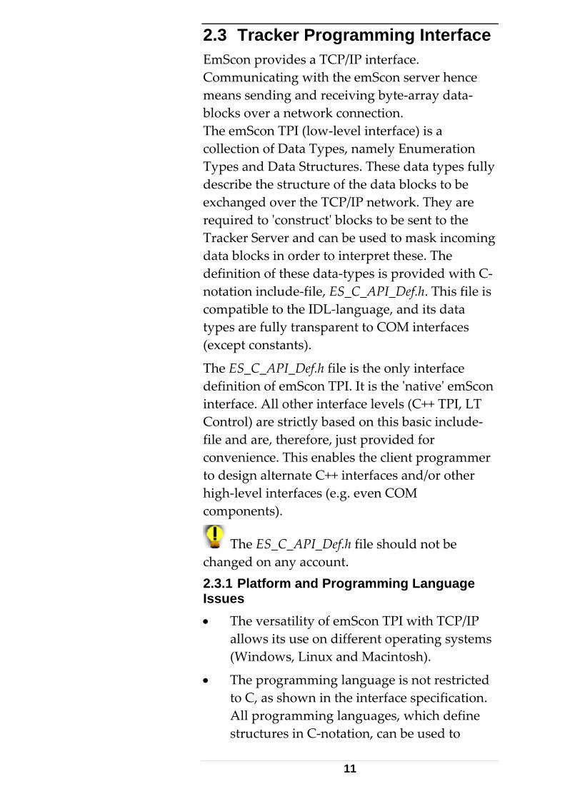
2.3.4 Working Conditions The table below shows the valid working ranges for selected parameters. Level 1
A Warning will be issued message when range is outside level 1 limits, but within level 2 limits. (In other words: Values are outside Leica specified working ambient conditions but still accepted. Should be used with caution.
14
Working ambient conditions
Minimum value Maximum value
Temperature + 5°C + 40°C Height above sea level/elevation (not relevant for software) -500 m +3000 m Air pressure 600 mbar 1170 mbar Relative humidity 10% 90% Refraction index IFM 1.00015 1.000331 Refraction index ADM 1.000152 1.000336
Level 2
An Error message occurs when trying to set a value outside the specified range. The values are rejected.
Storage ambient conditions (extended working range)
Minimum value Maximum value
Temperature -10°C + 60°C Height above sea level/elevation (not relevant for software) -2000 m +7000 m Air pressure 330 mbar 1400 mbar Relative humidity 0% 100% Refraction index IFM 1.000077 1.000419 Refraction index ADM 1.000078 1.000425
15
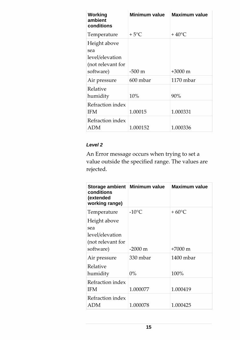
2.3.5 Coordinate Parameter Triplets The values of coordinate parameter triplets (often named as Val1,Val2 and Val3) in most data structures, depend on the currently active coordinate system type and the currently active units. In addition, measured coordinate values (output) and positioning values (input) are transformed according to currently set transformation- and orientation parameters. Coordinate values for 'filters' (Sphere, Box, Grid) differ from case to case. Details and exceptions are explained in the reference section.
The orientation / transformation filters can be switched off through flags provided by thesystem settings. Using the default values for orientation and transformation parameters' (0,0,0,0,0,0)/(0,0,0,0,0,0,1) mean invariant transformations.
Coordinate system type
Val1 Val2 Val3
Cartesian (RHR, LHR)
X Y Z
Spherical H V D (=R) Cylindrical R Phi (=H) Z
X, Y, Z Cartesian coordinate values
H Horizontal V Vertical
angle Angle
D Distance (=Radius)R Radius PHI Horizontal Angle
(=H)
Different notations of values in different systems (Phi instead of H, D instead of R)
16
maintain continuity with previous releases of application software.
2.3.6 Persistency The Tracker Server keeps settings (such as Units, CS-type, Reflector type etc.) persistently. Recent values will be restored, on restart of the Tracker- server.
It is recommended to initially set the required settings, on every client startup – as good programming practice. 2.3.7 Default Settings List of the most common parameters and their default factory- settings:
• Orientation parameters:{0,0,0,0,0,0}
• Transformation parameters:{0,0,0,0,0,0,1} (scale factor is 1)
• CS-Type: RHR (right handed rectangular)
• Length: Meter
• Angle: Radian
• Temperature: Celsius
• Pressure: Hectopascal
• Rel. Humidity: 70%
• Temperature: 20.0°C
• Pressure: 1013.25 mbar (760 mmHg)
• Measurement mode: Stationary
• Temperature range: Medium
• Reflector: None
• Interferometer refraction index: 1.0
• ADM refraction index: 1.0
• Stationary point measurement time:2500 ms
• Continuous measurement; time: 1000 ms
17

• Continuous measurement; number of points: 100
• Statistic mode: Standard
• Region and grid mode parameters: Arbitrary.
Other, less- common settings are described in the command reference section. 2.3.8 Version Backward Compatibility New data types/packets with evolving server versions This is a very important issue in order to prevent client application software adjustments upon future emScon server software upgrades. The coming versions of emScon will include arrival of new/extended data over the TCP/IP connection, such as new packet types, status messages and new error messages. Existing client applications will not be broken in combination with future emScon server versions, with one important caveat.
Backward compatibility will be provided, in that existing packets/information structure are neither changed nor removed. In practice, this generally means that the default case in switch statements should always be treated as 'neutral' (no action).
Example:
The enum ES_SystemStatusChange in v1.2 contains only two members. enum ES_SystemStatusChange { ES_SSC_DistanceSet, ES_SSC_LaserWarmedUp, };
EmScon 1.2 had only two system status change events, as shown above. With emScon version 1.4 (and higher), many more status change events have been appended (See C- API def file).
18

A (v1.2) programming statement as follows would cause an 'Unexpected Status' message, with (v1.3 and higher) emScon server upgrades. switch (status) { case ES_SSC_DistanceSet: MessageBox(“ADM Distance re-established”); break; case ES_SSC_LaserWarmedUp: MessageBox(“Laser is now ready”); break; default: MessageBox(“Unexpected Status”); break; // WRONG!!! };
Solution:
Ignore the default case with no 'default' entry tag or one that just has an effect to debug versions. default: // No action at all break; or default: // no effect to retail versions TRACE(“Unexpected Status”); ASSERT(false); break;
In short: emScon client application only must interpret KNOWN, i.e. defined data according to enums/structs in C- API def file. All other data must be ignored.
Only if this rule is attended, existing emScon client applications will also run with future emScon server upgrades. Otherwise, application source may need to be adjusted to be compliant to new server versions.
Applications supporting different server versions
If an application is required to support tracker hardware with different capability and/or several emScon server versions, some important version checking issues apply. Consider for example that the same application should be able to deal with emScon 1.5 (3D only) as well as with emScon 2.0 and up (3D trackers as well 6Dof systems).
19
Since newer emScon server versions always are backward compatible, that is, all previous commands are also contained in the newer version, there is usually no problem (exceptions see previous chapter) to run an already existing application on a newer server version. The problem starts if developing a new application, which should for example support 6Dof systems (emScon server V2.0 at least), but should also be able to deal with 3D trackers running in combination with an emScon 1.5 server. In order to run properly, such an application should check the server version upon startup and make provisions to prevent calls not suitable to a particular server version.
The version info to query is part of the information delivered by the ‘GetSystemStatus’ command. (ESVersionNumberT esVersionNumber). Depending on the server version the application is connected to, it has to allow/prevent commands being executed. If the queried server version for example evaluates to 1.5, the application would have to block (for example gray-out menus) all 6Dof related commands. See ‘enum ES_Command’ in file ‘ES_C_Api_def.h’ for availability of commands in which version. There are comments such as // New commands added for release 2.0 2.3.9 Sample Code The samples/tutorials, which are part of the SDK and which have to be regarded as integral part of this manual, show the principles of TPI programming in terms of ready to compile/use applications. However, the sample applications may not be of
20
real practical use, with respect to the specific TPI commands they implement. The focus of the samples is set to show principles of tracker control.
In a practical application, in order to get accurate results, it is crucial to implement all the steps as listed under 'Initial steps'.
The number of files and overhead in the samples has been kept to a minimum. Code generated from wizards, such as recompiled headers, icon, res2 includes and 'cosmetic functions', have been stripped off.
See also the numerous comments in the sample source files and the 'ReadMe.txt' files in each sample folder.
Error Handling
The samples do not always implement complete error handling and may need to be run through the debugger in order to find failure reasons.
Interface Design
The user interface design is kept at a minimum level (for example, unavailable buttons are not grayed out). Such items are general issues of Windows programming.
Hard Coded Information
The samples may contain some hard-coded information (IP address/coordinate values) that might be adapted to the local environment.
21
2.4 Application Initial Steps 2.4.1 Essential Steps A client application must carry out all steps listed below upon startup. Omitting some of these steps may prevent the tracker from measuring or lead to inaccurate results. Inaccurate results are difficult to detect.
Setting correct environment parameters (temperature, pressure, humidity) or configuring the system for automatic, environment parameter reading is crucial.
Most of the Settings ('Set'- commands) remain persistent. That is, they will be the same after a system restart. However, it is strongly recommended that an application always confirms these settings upon startup. This is because another application (e.g. emScon Base User Interface) could have accessed the tracker server in-between and could have changed the settings.
Note that most of the sample applications are not complete to this respect – the intention of the Samples is to show programming principles only. See also Leica Tracker/Training Manual.
22

2.4.2 Command Sequence for 3D Measurements 3D Measurements are performed to a (currently selected) Reflector. The selected Measurement mode must apply to one of the 3D modes. The tracker does not require a T-Cam, although there might be one mounted.
Steps TPI command
1. Establish TCP/IP connection.
Depends upon TCP/IP communication – See different samples
2. Set units (length, angle, temperature and pressure)
ES_C_SetUnits
3. Set current environmental temperature, pressure and humidity
ES_C_SetEnvironmentParams,
4. Initialize the Laser Tracker
ES_C_Initialize
5. Select desired 3D Measurement mode (Stationary, ContinuousTime..)
ES_C_SetMeasurementMode
6. Query all defined Reflectors
ES_C_GetReflectors
7. Select the Reflector being used
ES_C_SetReflector
23

8. Go Bird Bath (optional, if Tracker equipped with an ADM) For 6D modes, the tracker will move to zero position instead; GoBirdBath does not make sense for Probes
ES_C_GoBirdBath
9. Set Station Orientation parameters
ES_C_SetStationOrientationParams
10. Set Transformation parameters
ES_C_SetTransformationParams
11. Set Coordinate system type (RHR, LHR…)
ES_C_SetCoordinateSystemType
In addition, a valid mechanical Tracker compensation must be active. This is usually always the case (supposed the Tracker compensation once has been performed or imported). However, there can be exceptions when installing new software or importing compensation data. The active compensation is a persistent setting which can be changed by a ‘SetCompensation’ TPI command (or by selection within the compensation tree- representation in the BUI- Application). See description of ‘GetCompensations / GetCompensation / SetCompensation’.
24

2.4.3 Command Sequence for 6DOF Measurements 6DOF Measurements are performed to a T-Probe, which will be recognized automatically by the system.. The selected Measurement mode must apply to one of the 6DOF modes. A T-Cam must be mounted.
Steps TPI command
1. Establish TCP/IP connection.
Depends upon TCP/IP communication – See different samples
2. Set units (length, angle, temperature and pressure)
ES_C_SetUnits
3. Set current environmental temperature, pressure and humidity
ES_C_SetEnvironmentParams,
4. Initialize the System
ES_C_Initialize
5. Select desired 6DOF Measurement mode
ES_C_SetMeasurementMode
6. Ensure that 'Keep Last Position' flag is enabled
ES_C_SetSystemSettings OR ES_C_SetLongSystemParameter
7. Set Station Orientation parameters
ES_C_SetStationOrientationParams
8. Set Transformation parameters
ES_C_SetTransformationParams
9. Set Coordinate system type (RHR, LHR…)
ES_C_SetCoordinateSystemType
25
In addition, apart from a valid mechanical Tracker compensation (see 3D), compensations must be present and active for TCamToTracker, Probe and TipToProbe (supposed all these compensation processes have once been performed or imported). Active compensations are persistent settings that can be changed by the several ‘Set…Compensation’ TPI commands (or by selection within the compensation tree- representation in the BUI- Application). See description of ‘Get…Compensations / Get…Compensation / Set…Compensation’. Selection of TCam and Probe compensation only mean a ‘hint’ to the system. The compensations themselves only become really active if a matching TCam (i.e. the compensation must match the serial number of the TCam) is being mounted respectively a matching Probe is being attached and recognized by the camera.
26

2.4.4 Initial Steps Description in Detail Description of some commands that require more explanation.
Initialize Laser Tracker
Implication Comment
Initialize encoders and internal components
This command has to be performed every time you set up a new Leica Tracker system station. It is strongly recommended to use this function 2-3 times a day to initialize encoders and its internal components. This is important due to thermal expansion of the tracker hardware, which has a direct influence on the measurements
27

Set Current Environmental Parameters
Implication Comment
Calculate and Set index of refraction
With the input of the environmental temperature, pressure and humidity, the system calculates the light refraction index of the interferometer (IFM) and the absolute distance meter (ADM). These parameters have a direct influence on the distance measurement A change of 1°C causes a measurement difference of 1ppm.
A change of 3.5mbar causes a measurement difference of 1ppm.
Change environmental parameters when significant changes take place.
Default values: 20.0 °C, 1013.3 mbar
28

Set Reflector
Implication Comment
Select a specific reflector A wrong reflector results in a wrong initial IFM distance, e.g. when using the Go Birdbath command. This has a direct influence on the distance measurement.
Tooling ball reflector (TBR) = 5.310 mm Cat eye = 59.114 mm
There is usually more than one reflector defined. These can be queried from the system by using the 'GetReflectors' command. This shows the relation between the ID and the Name (Reflector Type). The ID can then be passed to the 'SetReflector' command to activate it. Note that this setting remains persistent. Nevertheless it's strongly recommended that an application upon launch at least checks whether the desired Reflector is set More info: Chapter 8: 'Get Reflectors' command
29
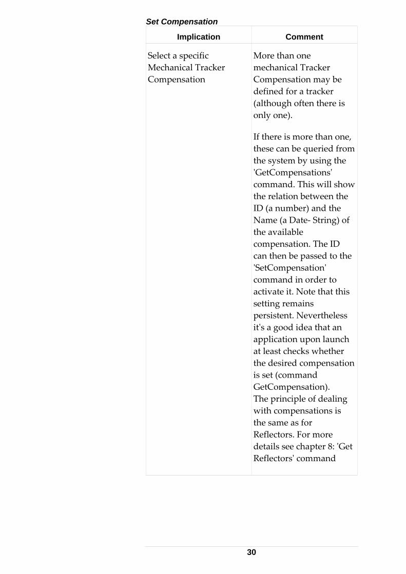
Set Compensation
Implication Comment
Select a specific Mechanical Tracker Compensation
More than one mechanical Tracker Compensation may be defined for a tracker (although often there is only one).
If there is more than one, these can be queried from the system by using the 'GetCompensations' command. This will show the relation between the ID (a number) and the Name (a Date- String) of the available compensation. The ID can then be passed to the 'SetCompensation' command in order to activate it. Note that this setting remains persistent. Nevertheless it's a good idea that an application upon launch at least checks whether the desired compensation is set (command GetCompensation). The principle of dealing with compensations is the same as for Reflectors. For more details see chapter 8: 'Get Reflectors' command
30
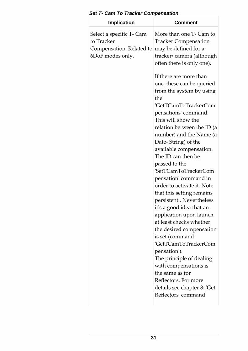
Set T- Cam To Tracker Compensation
Implication Comment
Select a specific T- Cam to Tracker Compensation. Related to 6DoF modes only.
More than one T- Cam to Tracker Compensation may be defined for a tracker/ camera (although often there is only one).
If there are more than one, these can be queried from the system by using the 'GetTCamToTrackerCompensations' command. This will show the relation between the ID (a number) and the Name (a Date- String) of the available compensation. The ID can then be passed to the 'SetTCamToTrackerCompensation' command in order to activate it. Note that this setting remains persistent . Nevertheless it's a good idea that an application upon launch at least checks whether the desired compensation is set (command 'GetTCamToTrackerCompensation'). The principle of dealing with compensations is the same as for Reflectors. For more details see chapter 8: 'Get Reflectors' command
31

Set Probe Compensation
Implication Comment
Select a specific Probe Compensation. Related to 6DoF modes only.
More than one Probe Compensation may be defined for a tracker/ camera (although often there is only one).
If there is more than one, these can be queried from the system by using the 'GetProbeCompensations' command. This will show the relation between the ID (a number) and the Name (a Date- String) of the available compensation. The ID can then be passed to the 'SetProbeCompensation' command in order to activate it. Note that this setting remains persistent. Nevertheless it's a good idea that an application upon launch at least checks whether the desired compensation is set (command 'GetProbeCompensation')The principle of dealing with probe compensations is the same as for Reflectors. For more details see chapter 8: 'Get Reflectors' command
32

Keep Last Position Flag
Implication Comment
Makes the laser beam stay at its current position if the beam is broken.
Enabling this flag is optional for 3D measurements (it makes only sense if the Tracker is equipped with an ADM). This flag is cleared by default. For 6DOF measurements, enabling this flag is compulsory to prevent the laser going to home position upon a beam break.
(automatically remeasures reference distance to the Reflector or T-Probe after the laser-beam has been lost.)
There are two ways to control this flag, either through the command ‘SetSystemSettings’ or through ‘SetLongSystemParameter’
See also 1.4.3
33
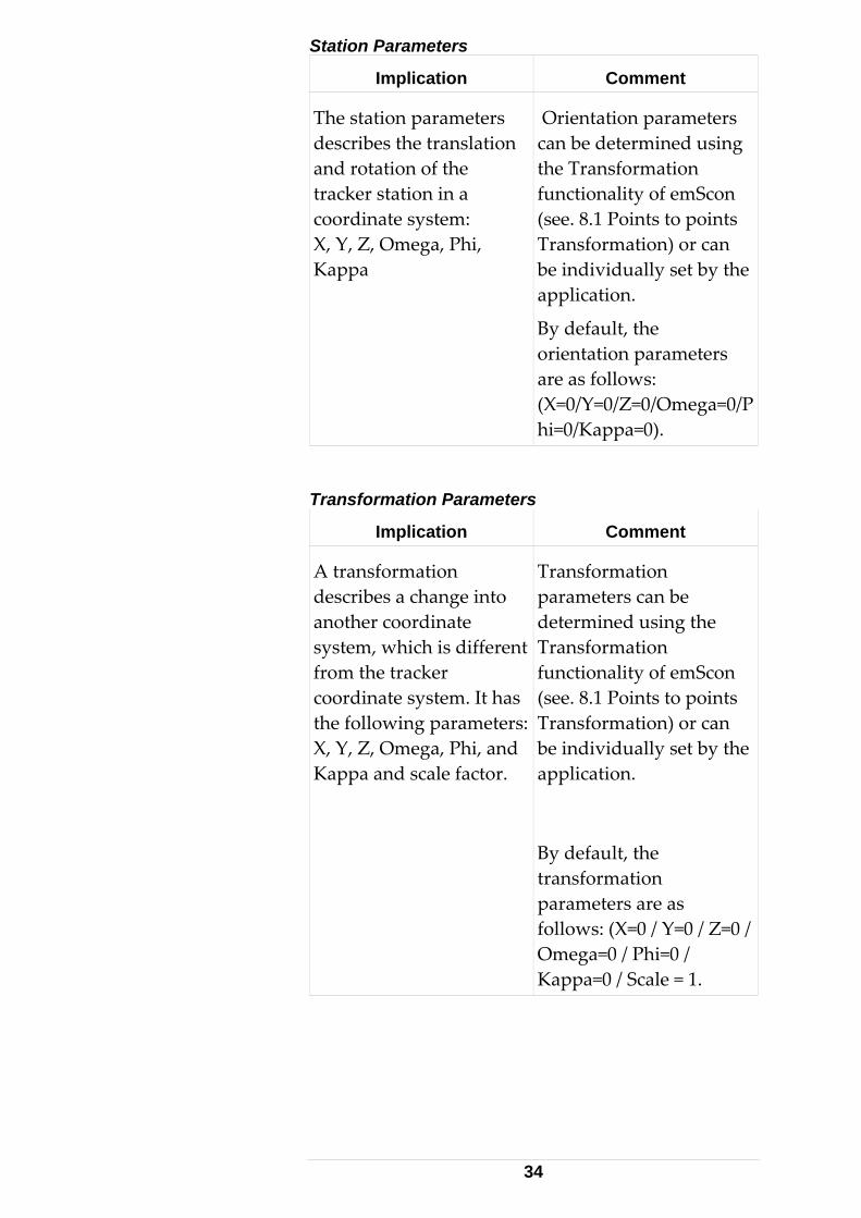
Station Parameters
Implication Comment
The station parameters describes the translation and rotation of the tracker station in a coordinate system: X, Y, Z, Omega, Phi, Kappa
Orientation parameters can be determined using the Transformation functionality of emScon (see. 8.1 Points to points Transformation) or can be individually set by the application.
By default, the orientation parameters are as follows: (X=0/Y=0/Z=0/Omega=0/Phi=0/Kappa=0).
Transformation Parameters
Implication Comment
A transformation describes a change into another coordinate system, which is different from the tracker coordinate system. It has the following parameters:X, Y, Z, Omega, Phi, and Kappa and scale factor.
Transformation parameters can be determined using the Transformation functionality of emScon (see. 8.1 Points to points Transformation) or can be individually set by the application.
By default, the transformation parameters are as follows: (X=0 / Y=0 / Z=0 / Omega=0 / Phi=0 / Kappa=0 / Scale = 1.
34
Coordinate System Type
Implication Comment
Selects the coordinate system type: RHR/LHR X, LHR Y, LHR Z/CCW/CCC/SCW/SCC
The TPI delivers the data in the current coordinate system type. By default the tracker system will work in the right handed rectangular coordinate system (RHR) type:
3D rectangular coordinates are defined by 3 mutually perpendicular axes X, Y and Z given in the order (X, Y, Z).
Since the axes can be arranged in two different ways, right and left-handed systems are defined according to the convention illustrated in a simple 2D case.
Cylindrical Clockwise (CCW), Cylindrical Counter Clockwise (CCC). In a cylindrical system the X and Y values are expressed in terms of a radial (distance) offset from the Z-axis and a horizontal angle of rotation. The Z coordinate remains the same.
35

Implication Comment
Spherical Clockwise (SCW), Spherical Counter Clockwise (SCC). In a spherical system a point is located by a distance and two angles instead of the 3 coordinate values along the rectangular axes. For axes labeled XYZ, with Z vertical, the point is located by its distance from the origin, horizontal angle in the XY plane and zenith angle measured from the Z-axis.
36

3 C - Interface
3.1 Low-level TPI Programming 3.1.1 Preconditions Using the C interface requires some particular C- programming knowledge. A programmer should at least know about asynchronous programming concepts, TCP/IP socket programming and multi-threading.
The description of the enums/structs in this chapter may be slightly discrepant to the contents of the ES_C_API_Def.h file in the SDK. In case of discrepancies, the information in the ES_C_API_Def.h file should be regarded as correct.
This chapter completely and exclusively relates to the file 'ES_C_API_Def.h', which is part of the EmScon SDK. All Enumeration types and Structures are described in this header file. This header file acts as an integral part to this manual and it might be helpful to have it open in parallel to this document since the information is much more condensed in the header file. 3.1.2 Recommendation Although the C- interface makes up the native programming- interface to emScon, it is not usually recommended to write applications directly using the C- interface. Rather use the much more convenient C++ interface. In contrast to the C++ interface, the C-interface requires much more coding lines and comprises
37
the danger of doing initialization errors for structures (aka 'copy/paste errors'). However, since it's the native interface, the enumeration types and structures of the C- interface serve as main- reference. The same enumeration types and parameters will show up in the C++ interface as well. Hence even when using the C++- interface, looking up information in this chapter 'C- Interface' might be essential.
3.1.3 Byte Alignment Data packets have a 4-Byte alignment convention as a Visual Basic default – small data packets sent over the network. The VC++ statement #pragma pack (push, 4), before user-defined structure definition, uses 4 Byte alignment – VC++ default is 8 Byte. The statement #pragma pack (pop) sets the alignment back to the previous value.
Use only 4 Byte alignments for TPI structures.
These are Microsoft VC++ specific statements. When using a non-Microsoft compiler, #pragma pack (push, 4) and pragma pack (pop) may have to be replaced or removed respectively.
The following include statement prepares the C_API_Def.h file for Byte alignment in Linux/ Win32.
4 Byte alignments for other platforms must be inserted. #ifdef _WIN32 #pragma pack (push, 4) #elif defined __linux__ #pragma pack (4) #elif #error Insert here directive to ensure 4 Byte alignment for other platforms (Unix, MAC) #endif
3.1.4 Little/Big Endians Non-Intel based workstations, for example M68000 based workstations like SUN, Apple or
38
IBM RS6000 series, use different endians for double values. The client application (the TCP/IPcommunication interface respectively) requireappropriate meas
s
ures to interpret numerical values correctly.
.The Tracker Server is Intel based. All values are provided in the little endian format.
arnings for s of data types.
ES_C_API_DEF_H
3.1.5 Preprocessor Statements The following statements show a common practice to avoid multiple inclusion of the same include-file while compiling a .CPP module. In case of nested inclusion of the ES_C_API_Def.h
ts will prevent wfile, these statemenmultiple definition#ifndef #define ES_C_API_DEF_H … #endif
3.1.6 TPI 'Boolean' Data Type No native Boolean data-type is available in C. C uses the integer basic type for Boolean values. Forconvenience, a platform- independent ES_BOOL
ced for the ES_API:
a 4
max
type has been introdu
typedef int ES_BOOL
Neither BOOL (which is 2 Bytes and Microsoft-specific) nor bool (which is 1 Byte and specific to newer C++ revisions) has been used. By usingByte Boolean (= int), pure C compliance and
imal portability is assured.
This relates only to the C interface, ES_C_API_Def.h. The C++ interface as well as custom programs may use any compatible Boolean type. Boolean type variables used in ES C
PI structs must be 4 bytes. A
39
3.1.7 Enumeration-Type Members Numerical representation Enumeratrepresented by integer values. Numbers cassigned explicitly to particular enum values; this the case for all enumeration types defined for emScon.
ion-type members in C are internally an be
is
his approach has some advantages for
ing languages other
than C/C++. However, some non-standard C/C++ c y provide ddata types. For TPI clients, it is necessary to use t ollowing standard si
pe g)
ely) 8 Bytes
long)
Tapplication debugging . However, applications should never use the numerical values directly. Always use the according symbol-names.
3.1.8 Basic C Data Type size of TPI StructuresThis is relevant for programm
ompilers ma ifferent sizes of basic
he f zes: Data tyEnum values
Size 4 Bytes (= int 32 or lon
Long 4 Bytes Int 4 Bytes Short 2 Bytes (for Unicode
strings exclusivDouble ES_BOOL 4 Bytes (= int 32 or
3.2 Communication Basics 3. Commands 2.1The Tracker Server can be controlled only
ffe
ers are called property setting
Set<CommandName> commands. The syntax of
through commands sent over TCP/IP. Commands di r in the count of parameters they take.
• GoBirdBath is an example for a non-parameter taking command.
• PointLaser (x,y,z) takes 3 parameters.
The majority of commands taking parametused for so-
40
each command – whether taking parameters or not – is defined by its <CommandName>CT structure.
These structures need to be initialized properly. Refer to C- Programming instructionssection. 3.2.2 Command Answers Every command causes an asynchronous answer, with an acknowledgment. The command-ty'cookie' previously sent to the Tracker Server isechoed back, padded with information whethe
pe r
for
tructure defines e contents of a command answer. However,
s of
ure, the return tatus (its numerical representation or enum-
-data
by
the command succeeded or not, and (optionally) padded with command specific data. Depending on the command type, this echo can occur immediately, or may take several seconds (example for FindReflector or Initialize Tracker).
Generally, a <CommandName>RT sththere are some special cases in the case of measurements commands. The command answers can be categorized into several subtypes as listed below.
Non-data Returning Command Answers
This command answer-type essentially consista command type 'cookie' with the return status 'succeeded' or 'failed'. In case of failsstatus value) may indicate the reason. Nonreturning commands all share the same basic return type structure. Find Reflector is an example of a non-data returning command. Property-data Returning Command Answers
Properties are the (current) system settings of theTracker Server. Properties can be retrievedGet<xxx> commands. All Get<xxx> commands
41

return their results in a Get<xxx>RT structure.RT structure for eachrespect to its data members. Data members wonly a Get… with no corresponding Set… command can be individual basic-type or enuparameters (int, double , enum...) . Example: GetSystemStatusRT. However, the normally there is a command-
The command differs with
ith
m
).
an one command. This avoids code duplication.
. If a Set command
e
ingle Measurement Answers
These are answers that follow to a previously issu
nts are often also referred to as
specific sub structure (example GetUnitsRT contains a SystemUnitsDataT sub structureIn other words: a sub- structure is available, when the same parameters are used for more th
Set/Get commands rarely failfails (return status not OK), the supplied parameters are usually out of valid range. Threturn status informs about the failure reason. S
ed Start<xxx>MeasurementCT command. Single measuremeStationary measurements.
Applies only when the measurement mode is set to stationary.
•
he
• ned to
t is r
sult type indicates a ingleMeasResultT structure, and
ES_DT_StationaryProbeMeasResult indicates
In case of a failure (which is frequent for measurement commands), a Start<xxx>MeasurementRT structure with terror code is returned.
In case of success, instead of a Start<xxx>MeasurementRT (not desigtake sensor results), a specifically designed measurement type-related data packeeceived. For example, a
ES_DT_SingleMeasReS
42

arrival of a ProbeStationaryResultT.
A successful measurement always returns such a data-packet.
Mu -Measurement Answers
e apply to tracker related continuous lti
Thesmeasurements only. The measurement mode is set to one of the non- stationary modes.
• In case of success, not only one packet, but also
ackets contains a e' (atomic)
• In case of failure, as with single measurement answers, a Start<xxx>MeasurementRT with error code isreturned.
a series of multi-measurement packets arrive. Each one of these pvarious-sized array of 'singlmeasurements.
See also structures 'MultiMeasRe'MultiMeasResult2T' and 'ProbeContinuousResultT'.
Only the first element of the measurement array is covered by these structures, although the index is valid from 0…numberOfResults-1. There is another significan
sultT',
•
t difference to single ta
• ys arrive w
urementRT confirmation is therefore ssential for continuous modes.
measurements. Before the measurement dapacket stream starts, a StartMeasurementRTwith command status OK arrives (acknowledge that the ‘start’ command hasarrived).
Single measurement results alwaithin a certain time span. This is not the
case with continuous measurements (Grid Mode, big time separation criteria.). A StartMease
A multi-measurement stream runs until
43

explicitly stopped, StopMeasurement or until
d
ations, ES_C_GetTipAdapters. do not fit any of the above categories.
l) are treated ay.
specified time or count thresholds are reached.
Special Command Answers
Some commands, such as ES_C_GetReflectors anES_C_GetTransformedPoints, ES_C_GetCompens
Generally spoken, all commands starting with 'Get' and ending with an 's' (i.e. plurain a special w
ES_C_GetReflectors must not to be mixewith ES_C_GetReflector (missing 's').
Convention:
The answer to these commands is made upmany answer-packets as reflector types (otransformed points, Compensations, Tips...) are available from the Tracker Server. These answers mainly resolve the relation between item name (string) and item ID (numerical ID), for example the relation betwReflector name and ReflectoA
d up
of as r
een r ID.
part from different other information, the ontain (redundant) information on
ber of
Example: short ReflectorName[32] declaration. It can consist of a
packets also cthe total number of items and the numpackets expected to arrive.
Convention:
All string-type names are in Unicode representation –cmaximum of 32 characters, however, since 'short'is 16 bit, there are 16 bits for every character (not only one Byte).
44
ReflectorPosResultT and Probbe seen as a special command answers. These are ES_DT_ReflectorPosResult / ES_DT_ProbePtype packets and are received whenever the tracker is locked onto a reflector (3 measuper second), supposed the 'SendReflectorPositionData' system- setting flag isenabled. This mechanism can be used in applications providing graphical representatof reflect
ePosResultT can also
osResult
rements
ion or/probe motion, even while no
ontinuous measurement is in ongoing. y of the positions provided
ipt of these measurements
s ES_DT_Error are not d
e the highly 'asynchronous' behavior of
cNote that the accuracare limited. The rececan be switched on/off. It is switched off by default.
3.2.3 Error Events Most error-type data packet
irect reactions to commands. They are 'unsolicited' and can occur at any time. Thesconfirm emScon communication. A typical example is the 'Laser beam broken' event.
Command directly contain the error status in their answer structure in case of command
ccur
is tusChange. The handling is the
ame as with error events, with the only difference that there is only one parameter.
failure. ES_DT_Errors type answer packets are only used for so called 'unsolicited errors' (which can oat any time, regardless of a command).
3.2.4 System Status Change Events Although already present in version 1.2 (only two events), there has been an inflation of such events since then. The appropriate packet typeES_DT_SystemStas
45
IMPORTANT: See chapter 'Version Backward
con v1.5 and
ve
oF
easurements. The only difference is that other
overview of the related co
3D Packets/Commands Probe)
Compatibility' for convention about handling 'unknown' data.
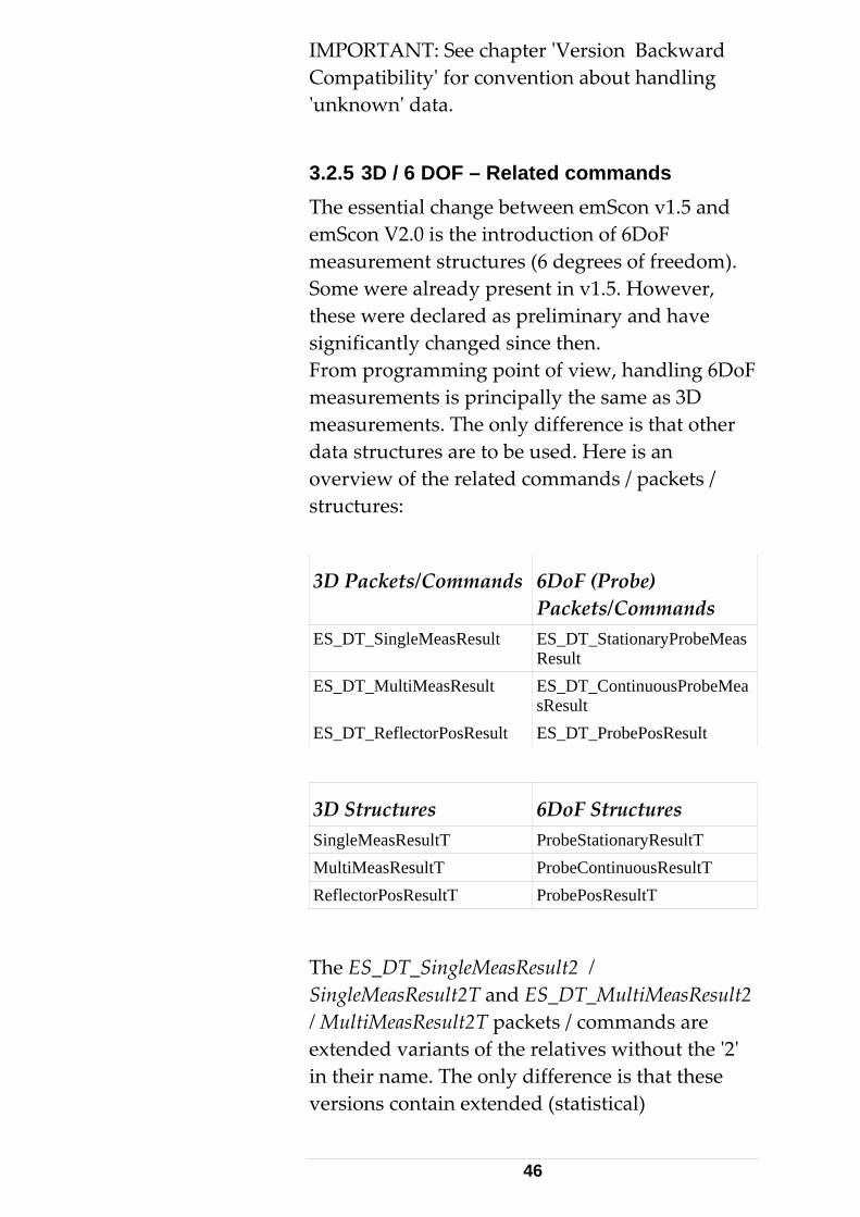
3.2.5 3D / 6 DOF – Related commands The essential change between emSemScon V2.0 is the introduction of 6DoF measurement structures (6 degrees of freedom). Some were already present in v1.5. However, these were declared as preliminary and hasignificantly changed since then. From programming point of view, handling 6Dmeasurements is principally the same as 3D mdata structures are to be used. Here is an
mmands / packets / structures:
6DoF (Packets/Commands
ES_DT_SingleMeasResult ES_DT_StationaryProbeMeasResult
ES_DT_MultiMeasResult obeMeaES_DT_ContinuousPrsResult
ES_DT_ReflectorPosResult ES_DT_ProbePosResult
3D Structures 6DoF Structures SingleMeasResultT ProbeStationaryResultT MultiMeasResultT ProbeContinuousResultT ReflectorPosResultT ProbePosResultT
The ES_DT_SingleMeasResult2 / SingleMeasResult2T and ES_DT_MultiMeasResult2 / MultiMeasResult2T packets / commands are extended variants of the relatives without the '2' in their name. The only difference is that these versions contain extended (statistical)
46
information. Applications passing measurements the 'CallTransformation' command should use
etStatisticMode' command.
ference
tothe '2'- variants since the transformation routine requires these extended statistics. See also 'S
3.3 C- Language TPI Re 3.3.1 Constants
ts that can be used
ddition to 'ES_C_API_Def.h'.
Constants for Transformation e used for the Weighting
9.2.6 ).
onst double ES_FixedStdDev = 0.0;
ES_UnknownStdDev knownStdDev = 1.0E35;
;
Use this value to weigh parameters according to rd Deviation.
This section names the constanwith C/C++ TPI programming.
The application needs to include the file 'Constant.h' in a
These constants arScheme of the Transformation process (see Section
c
ES_FixedStdDev Use this value (= 0.0) to indicate a parameter as fixed.
const double ES_Un
Use this value to indicate a parameter as unknown (not fixed).
ES_ApproxStdDev const double ES_ApproxStdDev = 1.0E15
its related Standa
See command 'SetTransformationInputParams' for details.
47

Other Constants The other constants defined in 'Constant.h' (Unit-
s) are for
Scon applications.
ration Types
The ES_DataType enumeration values are used to iden
in
Conversion related constantinformational reasons only and should not be directly referenced by em
3.3.2 EnumeThis section describes all enumeration types and their individual values.
ES_DataType
tify the type of data packets that are sent to/received from the Tracker Server on TCP/IP. There are 11 different packet types that differ size and structure.
The ES_DT_Command comprises many sub-d structure as well. HeaderT, which
e in all packets.
types that all differ in size anA related data type is Packetserves as a sub-structurenum ES_DataType { ES_DT_Command, ES_DT_Error, ES_DT_SingleMeasResult, ES_DT_MultiMeasResult, DT_StationaryProbeMeasResES_ ult, DT_ContinuousProbeMeasResult, ES_ ES_DT_NivelResult, ES_DT_ReflectorPosResult, ES_DT_SystemStatusChange, ES_DT_SingleMeasResult2, ES_DT_MultiMeasResult2, ES_DT_ProbePosResult, };
• cket contains a command (sent),
answer (received).
• ror formation.
ES_DT_Command
The data paor a commandRelated data structures: BasicCommandCT and BasicCommandRT (which are used as sub-structures of each command-related structure).
ES_DT_ErThe data packet contains error in
48

Such a packet means an 'Erexample 'beam broken'). It is not a reactionsome previous command and can occur at any time. Related data structure: ErrorRT.
ror event' (For of
one t'-
tT.
• ket contains results of a
ends
• MeasResult easResult, but
block
• MeasResult, but with
is, the data block nts each with 3 rotation
R
•
easurement.
• ES_DT_SingleMeasResult The data packet contains the result ofsingle (stationary 3D) measurement. 'Resultype packets can only be received. Related data structure: SingleMeasResul
ES_DT_MultiMeasResult The data paccontinuous 3D measurement. This type of result block is of variable size and depon the number of single measurements within a block. 'Result'- type values can only be received. Related data structure: MultiMeasResultT.
ES_DT_StationaryProbeThe equivalent to SingleMwith 6 degrees of freedom, i.e. the datacontains 3 angular values in addition to 3 coordinate values (apart from other data). Related data structure: ProbeStationaryResultT.
ES_DT_ContinuousProbeMeasResult The equivalent to Multi6 degrees of freedom, that contains measuremeparameters in addition to 3 coordinate position values (apart from other data).
elated data structure: ProbeContinuousResultT
ES_DT_NivelResult The data packet contains the result of aNivel20 (inclination sensor) m
Requires the Nivel sensor being connected to the Tracker directly. 'Result'-
49

type values can only be rRelated data structure: NivelResultT.
eceived.
be suppressed. eflectorPosResultT.
• ange ormation about a
•
.
t2T n the
easResultT. This is an
eas result' has lready
eak existing
T.
• ts of a
tistic
Mode'.
n the
• ES_DT_ReflectorPosResult: The data packet contains position information about the reflector. This type ofinformation is foreseen for special purposes and can Related data structure: R
ES_DT_SystemStatusChThe data packet contains infstatus change. Other than an error event, aSystemStatusChange event does not mean a failure. Related data structure: SystemStatusChangeT.
ES_DT_SingleMeasResult2 The data packet contains the result of one single (stationary) measurement, in case the statistic mode is set to ‘extended’. These types are mainly used for measurements used as input to the Transformation routine See command 'SetStatisticMode'. The difference is that SingleMeasResulcontains more statistical information thastandard SingleMadvanced feature. The default statistic mode is ‘standard’. (This 'type 2 mbeen introduced to avoid changes to apublished TPI definitions with earlier versions, in order not to brapplications. ). Related data structure: SingleMeasResult2
ES_DT_MultiMeasResult2 The data packet contains resulcontinuous measurement, in case the stamode is set to ‘extended’. See command 'SetStatisticThe difference is that MultiMeasResult2T contains more statistical information tha
50

standard MultiMeasResultT. The default statistic modR
e is ‘standard’. elated data structure: MultiMeasResult2T.
robePosResult
ES_
re provided by the TPI. A data packet of type
alues. The answer packet to a command returns
• ES_DT_ PThe equivalent to ES_DT_ReflectorPosResult,but related to probes with 6 Degrees of freedom. I.e. Not only the position, but also the rotation is supplied.
Command
This enumeration type names all commands that aES_DT_Command contains exactly one of these vthe same value for acknowledgment.
See struct 'BasicCommandCT' for details.
General Information related to each command:
The related data- structures for sending and
na
mand
stfix to get name of related send- structure (CT stands for CommandType)
ceive-
e are
e command escriptions (ES_C_...) and also at the related
structure descriptions (..CT, ..RT). To avoid too
1.) Naming Convention Send / Receive Structs
receiving data can be derived from the command me as follows:
• Remove the ES_C_ Prefix from the com
• Add CT po
• Add RT postfix to get name of related restructure (RT stands for ReturnType)
Example: Structures related to command 'ES_C_Initialize' are 'InitializeCT' and 'InitializeRT'
If CT/RT structures contain sub- structs, thesmentioned at each commands description.
Explanations are available at thd
51

much redundancy, descriptions are usually not be
rs
plicitly in the command following units of all parameters
units'. That is, in those
command:
- H
This applies to parameters sent as well as those recde
y one exception to this and StartNivelMeasurement
rees nits.
•
•
ch sed, an
ignore each second byte. See sample applications for examples.
repeated at both locations. Thus it might necessary to look- up command descriptions and related structure descriptions.
2.) Dimensions / Units of Paramete
Unless stated exdescription, theare always in 'currentunits the application/programmer has selected with the SetUnits
- Length- units
- Angle- units
- Temperature- units
- Pressure- units
umidity- units (currently only one: percent)
eived such as coordinates, standard viations, meteorological values...
• Currently, there is onlrule: The commdelivers the native Nivel20 inclination readings. These are milli-radiants and degCelsius, regardless of currently selected u
Other units include: - Time – units: These are always in milliseconds – unless stated differently. Example: a Stationary Measurement Time of '2000 'means two seconds.
String- type parameters: Strings as far as handled through the TPI are always in UNICODE (arrays of unsigned short). That is, two bytes are reserved for eacharacter. As far as pure ANSI text is uapplication can just
52
• Enumeration-type parameters: These are type-
. t
command, but not repeated at the description of the related 'Get..' command. It is obvious that these information apply to both 'Set..' and 'Get..'. (Although the valid range information is obsolete for 'Get..' commands).
safe with the related enum definition. Theparameters are described at the enum-definition location.
3.) Valid Parameter Ranges
This applies to parameters being sent to the system, typically with one of the 'Set..' commandWhere limitations apply, these are mentioned athe command description. See also chapter 'Working Conditions' in the 'Introduction' main chapter of this manual. Note that it is never possible to violate valid parameter ranges in such that the related 'Set..' commands do not accept values outside valid range and therefore will return with an error. Reading Instructions Set/Get Command- pairs.
Information about parameter representation in terms of current Units, Coordinate System- Type (CS-type), Transformation and Orientation is provided at the Description of the 'Set..'
53

enum ES_Command { ES_C_ExitApplication, ES_C_GetSystemStatus, ES_C_GetTrackerStatus, ES_C_SetTemperatureRange, ES_C_GetTemperatureRange, ES_C_SetUnits, ES_C_GetUnits, ES_C_Initialize, ES_C_ReleaseMotors, ES_C_ActivateCameraView, ES_C_Park, ES_C_SwitchLaser, ES_C_SetStationOrientationParams, ES_C_GetStationOrientationParams, ES_C_SetTransformationParams, ES_C_GetTransformationParams, ES_C_SetBoxRegionParams, ES_C_GetBoxRegionParams, ES_C_SetSphereRegionParams, ES_C_GetSphereRegionParams, ES_C_SetEnvironmentParams, ES_C_GetEnvironmentParams, ES_C_SetRefractionParams, ES_C_GetRefractionParams, ES_C_SetMeasurementMode, ES_C_GetMeasurementMode, ES_C_SetCoordinateSystemType, ES_C_GetCoordinateSystemType, ES_C_SetStationaryModeParams, ES_C_GetStationaryModeParams, ES_C_SetContinuousTimeModeParams, ES_C_GetContinuousTimeModeParams, ES_C_SetContinuousDistanceModeParams, ES_C_GetContinuousDistanceModeParams, ES_C_SetSphereCenterModeParams, ES_C_GetSphereCenterModeParams, ES_C_SetCircleCenterModeParams, ES_C_GetCircleCenterModeParams, ES_C_SetGridModeParams, ES_C_GetGridModeParams, ES_C_SetReflector, ES_C_GetReflector, ES_C_GetReflectors, ES_C_SetSearchParams, ES_C_GetSearchParams, ES_C_SetAdmParams, ES_C_GetAdmParams, ES_C_SetSystemSettings, ES_C_GetSystemSettings, ES_C_StartMeasurement, ES_C_StartNivelMeasurement, ES_C_StopMeasurement, ES_C_ChangeFace, ES_C_GoBirdBath, ES_C_GoPosition, ES_C_GoPositionHVD, ES_C_PositionRelativeHV, ES_C_PointLaser, ES_C_PointLaserHVD, ES_C_MoveHV, ES_C_GoNivelPosition, ES_C_GoLastMeasuredPoint, ES_C_FindReflector, ES_C_Unknown, ES_C_LookForTarget, ES_C_GetDirection, ES_C_CallOrientToGravity, ES_C_ClearTransformationNominalPointList, ES_C_ClearTransformationActualPointList, ES_C_AddTransformationNominalPoint, ES_C_AddTransformationActualPoint, ES_C_SetTransformationInputParams, ES_C_GetTransformationInputParams, ES_C_CallTransformation, ES_C_GetTransformedPoints, ES_C_ClearDrivePointList, ES_C_AddDrivePoint, ES_C_CallIntermediateCompensation, ES_C_SetCompensation, ES_C_SetStatisticMode, ES_C_GetStatisticMode, ES_C_GetStillImage, ES_C_SetCameraParams, ES_C_GetCameraParams, ES_C_GetCameraParams, ES_C_GetCompensation,
54

ES_C_GetCompensations, ES_C_CheckBirdBath, ES_C_GetTrackerDiagnostics, ES_C_GetADMInfo, ES_C_GetTPInfo, ES_C_GetNivelInfo, ES_C_SetLaserOnTimer, ES_C_GetLaserOnTimer, ES_C_ConvertDisplayCoordinates, ES_C_GoBirdBath2, ES_C_SetTriggerSource, ES_C_GetTriggerSource, ES_C_GetFace, ES_C_GetCameras, ES_C_GetCamera, ES_C_SetMeasurementCameraMode, ES_C_GetMeasurementCameraMode , ES_C_GetProbes, ES_C_GetProbe, ES_C_GetTipAdapters, ES_C_GetTipAdapter, ES_C_GetTCamToTrackerCompensations, ES_C_GetTCamToTrackerCompensation, ES_C_SetTCamToTrackerCompensation, ES_C_GetProbeCompensations, ES_C_GetProbeCompensation, ES_C_SetProbeCompensation, ES_C_GetTipToProbeCompensations, ES_C_GetTipToProbeCompensation , ES_C_SetExternTriggerParams, ES_C_GetExternTriggerParams , ES_C_GetErrorEllipsoid, ES_C_GetMeasurementCameraInfo, ES_C_GetMeasurementProbeInfo, ES_C_SetLongSystemParameter, ES_C_GetLongSystemParameter, ES_C_GetMeasurementStatusInfo, ES_C_GetCompensations2, ES_C_GetCurrentPrismPosition, };
• ES_C_ExitApplication Stop and reset the Tracker Server. Other than most commands, ‘ExitApplication’ takes effect even while another command may still be busy (Initialization, FindReflector..). However, there might be a delayed reaction in certain cases. This command thus can be used for ‘emergency aborts’ in those cases where ‘StopMeasurement’ is not sufficient. Applications cannot rely on that this command will send any confirmation (command completed, SystemStatus change events). Depending on context, there may be a reaction or not. Applications should close the TCP/IP connection after having sent the ‘ExitApplication’ command. Note: ‘ExitApplication’ and ‘StopMeasurement’ are the only two exceptions of commands that cause immediate reaction while some other
55
command is still pending. All other commands will return ‘Server busy instead’. (Hint: This does not apply to the synchronous emScon COM interface (LTControl)).
• ES_C_GetSystemStatus Request status information about the system.
• ES_C_GetTrackerStatus Request status information about the tracker.
• ES_C_SetTemperatureRange Set the Trackers working temperature range.
• ES_C_GetTemperatureRange Get the Trackers working temperature range.
• ES_C_SetUnits Set Current Units. All length, angular, temperature, pressure and humidity- type parameters of all TPI- commands are represented in the currently selected units. Exception: Nivel20 (inclination sensor) readings are provided in the Nivel20 sensors native units (milli-rad, Celsius). Related structure: SystemUnitsDataT.
• ES_C_GetUnits Queries the currently active unit- settings. Related structure: SystemUnitsDataT.
• ES_C_Initialize Initializes the tracker.
• ES_C_ReleaseMotors Release the motor for horizontal and vertical tracker head movement in order to allow manual tracker head movement.
• ES_C_ActivateCameraView Activates the camera view. The mirror is turned upwards in order to direct camera view towards tracker head orientation.
56
Command only applies to Trackers equipped with an overview camera.
• ES_C_Park Send tracker to park position. The laser beam points towards the floor on the opposite side of the Bird bath.
• ES_C_SwitchLaser Switch the laser off or on. Usually used to switch off the laser overnight.
• ES_C_SetStationOrientationParams Set the 6 orientation parameters to be applied to measurements and positioning coordinates. Invariant orientation parameters are {0,0,0,0,0,0}. With these default settings, the tracker delivers measured coordinate values (and takes positioning values) in the instrument's CS. Orientation parameters values are also ignored if the applyStationOrientationParams system settings flag is not set. Station orientation parameters itself are in current units and current CS-type, but neither according to applied transformation settings nor to applied orientation settings (which would mean recursive). No range limitations apply. Related structure: StationOrientationDataT.
• ES_C_GetStationOrientationParams Queries the currently applied 6 orientation parameters. Related structure: StationOrientationDataT.
• ES_C_SetTransformationParams Set the 7 transformation parameters to be applied to measurements and positioning coordinates and to (part of) the input filters such as region parameters. Invariant transformation parameters are {0,0,0,0,0,0,1}. With these default settings, the tracker delivers data in the instrument's CS,
57
(or in the 'oriented system', if non-invariant orientation parameters are present). Transformation parameters are also ignored if the applyTransformationParams system settings flag is not set. Transformation parameters itself are in current units and current CS-type, but neither according to applied orientation settings nor to applied transformation settings (which would mean recursive)! No range limitations apply. Related structure: TransformationDataT.
• ES_C_GetTransformationParams Queries the currently applied 7 transformation parameters. Related structure: TransformationDataT.
• ES_C_SetSphereRegionParams Defines a spherical region. If the corresponding mode is active, measurements outside the region are suppressed. The interpretation of the parameters is subject to units, coordinate type, and transformation parameters. Related structure: SphereRegionDataT
• ES_C_GetSphereRegionParams Queries the currently valid sphere region parameters. Related structure: SphereRegionDataT.
• ES_C_SetBoxRegionParams Defines a box region. If the corresponding mode is active, measurements outside the region are suppressed. The box is connected to the object system given by the transformation parameters. It is defined by its diagonal, i.e. by two points in the object system. The coordinates of the points are subject to units and coordinate type (They are NOT subject to transformation parameters!)
58
A box region is described by a coordinate system parallel to the box edges and two opposite vertices. All coordinates of the first point must be less than those of the second one. If this condition fails on input, the corresponding coordinates are switched. Related structure: BoxRegionDataT.
• ES_C_GetBoxRegionParams Queries the currently valid box region parameters. Note that the retrieved point coordinate values can be different from those previously set by SetBoxRegion (Because of the condition that the coordinates of the first point must be less than those of the second one). However, the defined box will remain the same. Related structure: BoxRegionDataT.
• ES_C_SetEnvironmentParams Sets the environment parameters. (temperature, pressure and humidity). Parameters are in current units. For valid parameter ranges refer to chapter 'Working Conditions' in the 'Introduction' main chapter of this manual. Trying to set values outside the valid ranges will result in command failure. Related structure: EnvironmentDataT. See enum 'ES_WeatherMonitorStatus' for details on explicit and implicit updates of environmental parameters.
• ES_C_GetEnvironmentParams Queries the currently valid environment parameters. Related structure: EnvironmentDataT. See enum 'ES_WeatherMonitorStatus' for details on explicit and implicit updates of environmental parameters.
• ES_C_SetRefractionParams Set explicit Refraction Indices for
59

Interferometer and ADM. This is an advanced command and should only be used in real special situations. That is, if one wants to use his own formula for calculating the refractions from the environment parameters. SetRefractionParams will override those refraction parameters indirectly calculated and implicitly set by a previous call to SetEnvironmentParams. Note SetEnvironmentParams and SetRefractionParams are 'concurrent' commands. Both update the refraction parameters. Refraction indices are dimension-less. For valid parameter ranges refer to chapter 'Working Conditions' in the 'Introduction' main chapter of this manual. Trying to set values outside the valid ranges will result in command failure. A change of the environment parameters automatically causes an internal, implicit refraction parameter setting.
• ES_C_GetRefractionParams Query the currently valid Refraction Parameters for Interferometer and ADM.
• ES_C_SetMeasurementMode Sets the measurement mode of the tracker. Depending on this mode, a subsequent 'Start measurement' command will result in a 'Stationary measurement' (=single point measurement), a 'Continuous measurement' etc. See enum 'ES_MeasMode' for a list of modes supported.
• ES_C_GetMeasurementMode Queries the currently active measurement mode.
60

• ES_C_SetCoordinateSystemType Sets the coordinate system type. See 'ES_CoordinateSystemType' for a list of CS- types supported. All coordinate- type parameters of all TPI commands are represented in the currently selected CS-type.
• ES_C_GetCoordinateSystemType Queries the currently active CS-type.
• ES_C_SetStationaryModeParams Sets the properties for a stationary measurement, i.e. Measurement time and ADM use (usually do not use ADM upon measurement). Measurement time must lie between 500 ms and 100000 ms (0.5 – 100 seconds). Related structure: StationaryModeDataT.
• ES_C_GetStationaryModeParams Queries the currently valid Stationary Mode Parameters. Related structure: StationaryModeDataT.
• ES_C_SetContinuousTimeModeParams Sets the properties for a continuous time measurement. Related structure: ContinuousTimeModeDataT.
• ES_C_GetContinuousTimeModeParams Queries the currently valid Continuous Time Mode Parameters Related structure: ContinuousTimeModeDataT.
• ES_C_SetContinuousDistanceModeParams Sets the properties for a continuous distance measurement. Distance parameter is in current Length- units. No range limitation applies to distance parameters in theory, but there is a practical limitation given by tracker working space.
61

Related structure: ContinuousDistanceModeDataT.
• ES_C_GetContinuousDistanceModeParams Queries the currently valid Continuous Distance mode parameters. Related structure: ContinuousDistanceModeDataT.
• ES_C_SetSphereCenterModeParams Sets the properties for a Sphere Center measurement. Radius and SpatialDistance parameters are in current Length- units. No range limitation apply to distance and radius parameters in theory, but there is a practical limitation given by tracker working space. Related structure: SphereCenterModeDataT.
• ES_C_GetSphereCenterModeParams Queries the currently valid SphereCenterMode Parameters. Related structure: SphereCenterModeDataT.
• ES_C_SetCircleCenterModeParams Set the properties for a Circle Center measurement. Radius and SpatialDistance parameters are in current Length- units. No range limitation apply to distance and radius parameters in theory, but there is a practical limitation given by tracker working space. Related structure: CircleCenterModeDataT.
• ES_C_GetCircleCenterModeParams Queries the currently valid Circle Center Mode Parameters. Related structure: CircleCenterModeDataT.
• ES_C_SetGridModeParams Sets the properties for a Grid measurement. Grid value parameters are in current units, and according current CS-type. No range limitation apply to grid parameters in theory, but there is a practical limitation
62

given by tracker working space. Related structure: GridModeDataT.
• ES_C_GetGridModeParams Queries the current Grid Mode Parameters. Related structure: GridModeDataT.
• ES_C_SetReflector Sets the valid reflector type by its numerical ID. Attention: Reflector ID's must not be hard coded. They differ from emScon system to emScon system. Use command 'GetReflectors' to query the system for defined reflectors and appropriate ID-name/type mapping.
• ES_C_GetReflector Queries the ID of currently valid Reflector .
• ES_C_GetReflectors Queries all known reflectors of the Tracker Server. Apart from other information, mainly delivers the association between reflector names and their numerical IDs.
• ES_C_SetSearchParams Set criteria for reflector search abort (search radius and time out). Search radius is in current Length- units. Maximal search parameter is 0.5 meters. The search time should be set into a reasonable relation to the search radius. Large search radii result in extended search times unless limited by the search timeout value. The minimum value for the SearchTimeout is 10’000 ms (10 seconds). Note: was 2’5000 in previous emScon versions.
Related structure: SearchParamsDataT. For a detailed description see there.
• ES_C_GetSearchParams Queries the currently valid criteria for aborting a reflector search.
63
Related structure: SearchParamsDataT. For detailed description see there.
• ES_C_SetAdmParams Set parameters for the ADM (stability, time, retries). Attention: This is a 'dangerous' command. Lowering the stability criteria will result in measurement precision loss. Only change these values if really required due instable conditions (ground vibrations etc.) TargetStabilityTolerance is a distance parameter and is in current length- units. TargetStabilityTolerance must lie between 0.005 and 0.1 Millimeter. Leave this value as low as possible! (Default is 0.005). RetryTimeFrame is in milliseconds in the range between 500 and 5000. Related structure: AdmParamsDataT.
• ES_C_GetAdmParams Queries the currently valid ADM parameters. Related structures: SetAdmParamsCT, SetAdmParamsRT and AdmParamsDataT.
• ES_C_SetSystemSettings Sets system settings, a collection of flags to control the behavior of Tracker Server. See struct 'SystemSettingsDataT' for details. Related structures: SetSystemSettingsCT, SetSystemSettingsRT and SystemSettingsDataT .
• ES_C_GetSystemSettings Queries the currently valid System Settings. Related structure: SystemSettingsDataT.
• ES_C_StartMeasurement Triggers a measurement – regardless of the measurement mode. I.e. depending on selected mode, Start Measurement may start a Stationary3D- a StationaryProbe-, a Continuous3D- or a ContinuousProbe measurement. Once a continuous measurement (with
64
unlimited time/points) has been started, it can only be stopped on using ES_C_StopMeasurement (apart from beam break). Note: ‘StopMeasurement’ can also be used to interrupt some other lengthily taking (but deterministic) commands (Except on using the emScon COM [LTControl] synchronous interface – See Chapter ‘Proper Interface Selection’). Further details see description of ‘ES_C_StopMeasurement’.
• ES_C_StartNivelMeasurement Triggers a Nivel 20 (inclination sensor) measurement, if sensor is available. Note: result are in native Nivel20 units (milli- radiant, Celsius), regardless of the currently set angular and temperature units. This is an exception to the common convention. Reason: It does not make sense to provide very small angles (parts of milli- radiants) in Degrees or Gons.
• ES_C_StopMeasurement Stopping a continuous measurement is the main purpose of this command. However, this command can also be used to interrupt other long taking, but deterministic actions (This is a new feature introduced with V2.0 and is not available on earlier emScon versions). Commands that can be interrupted include: Stationary Measurements (if a long measurement time is applied), those Positioning Commands including a spiral reflector search (GoPosition, FindReflector..), and finally the ‘OrientToGravity’ and ‘Automated Intermediate Compensation’ processes. Note: the Tracker ‘Initialize’ command cannot be interrupted.
65
Interruption of long taking commands is also not possible when using the emScon COM [LTControl] synchronous interface. If an issue, use the asynchronous COM interface. For details see chapter ‘Proper Interface Selection’.
• ES_C_ChangeFace Changes the tracker face before the laser beam is attached to the same position.
• ES_C_GoBirdBath 3D Modes: Laser beam is sent to the Bird bath. The beam is 'attached' to the reflector in the Bird bath and the Interferometer distance is set to the known Bird- bath distance. This command is especially important for LT- series trackers without ADM. For such tracker, there is no other way to set the interferometer distance. 6D Modes: GoBirdBath does not make sense for a Probe. This command thus has a different effect while one of the 6D measurement modes is active. The laser beam is sent to zero position instead (which is on the opposite side of the BirdBath), where it can then be catched with the probe.
• ES_C_GoPosition Laser beam is sent to a specified location, followed by an implicit 'Find reflector'. The beam is 'attached' to the reflector (if found). Input is in current units, CS-type and according to applied orientation / transformation parameters. No range limitations apply to these parameters in theory, but there is a practical limitation given by tracker working volume. The useADM flag should always be set for trackers equipped with an ADM. If ADM flag is not set, the IFM distance is calculated from the supplied coordinates and
66
is set as the valid one. To be used with caution! The search time depends on the search radius. Large search radii result in extended search times, unless limited by the search timeout value selected by 'SetSearchParams'. See command 'SetSearchParams' for details. A ‘GoPosition’ command in progress can be interrupted with ‘ES_C_StopMeasurement’.
• ES_C_GoPositionHVD Laser beam is sent to specified location, followed by an implicit 'Find reflector'. Input is in current units as horizontal, vertical and distance parameters related to the values of the 'instrument CS' and 'raw' measurement values, regardless of current CS and CS-type. Range limitations apply with respect to the tracker elevation limits. The useADM flag should always be set for trackers equipped with an ADM. If ADM flag is not set, the provided distance is taken as new IFM distance. To be used with caution! The search time depends on the search radius. Large search radii result in extended search times, unless limited by the search timeout value selected by 'SetSearchParams'. See command 'SetSearchParams' for details. A ‘GoPositionHVD’ command in progress can be interrupted with ‘ES_C_StopMeasurement’.
• PositionRelativeHV Position (relative)the tracker head to the given horizontal and vertical angles. The angles are 'signed' values in order to specify the direction. Parameters are according to currently set angular units. Range limitations
67

apply with respect to the tracker elevation limits.
• ES_C_PointLaser Similar to ES_C_GoPosition, but laser beam is sent to the specified location only. A reflector is neither searched nor attached.
• ES_C_PointLaserHVD Same as ES_C_GoPositionHVD (laser beam is sent to the specified location), but a reflector is neither searched for nor attached.
• ES_C_MoveHV Command to start laser beam movement in horizontal, vertical direction, or to stop movement. Zero values mean 'stop movement'. The parameters for MoveHV are 'signed' values in order to specify the direction of movement. The parameters are 'speed values in the range between -100 < x < 100
• ES_C_GoNivelPosition This command moves the tracker head to one of the defined Nivel20 positions (1 to 4). The laser tracker moves at a slow speed to avoid disturbing the Nivel sensor. This command is used for the orient to gravity procedure.
• ES_C_GoLastMeasuredPoint Positions the laser beam to the location that has been last measured successfully in stationary mode.
• ES_C_FindReflector Searches a reflector at the given position. Reflector is attached if found. The approx distance is only required to calculate the 'opening angle' of the laser beam from the given search parameter. An inaccurate approx distance only has the effect that the real search radius will be bigger or smaller
68

than specified in SetSearchParams. It has no effect to measurement quality. Approx distance parameters are in current Length Unit. Although no range limitation applies in theory, there is a practical limitation given by tracker working space: 100 mm < approxDist <= 50000 mm. Note: the minimum value is 101 mm, not 100 mm! The search time depends on the search radius. Large search radii result in extended search times. See also command 'SetSearchParams'. A ‘FindReflector’ command in progress can be interrupted with ‘ES_C_StopMeasurement’
• ES_C_Unknown Used for initialization purposes only. Does not appear as an answer to a command .
• ES_C_LookForTarget Looks for a reflector at the given position and returns H, V values, if a reflector is present. Values are in current angular units. This command is mainly useful for LT- series of Tracker without ADM and should not be used in general.
• ES_C_GetDirection, Returns H, V values even without a reflector locked on. Values always are in current angular units.
• ES_C_CallOrientToGravity Triggers an ‘Orient to Gravity’ process. The 2 inclination parameters are returned as a result. Result values are in current angular units and are typically used as RotVal1, RotVal2 input values for the SetStationOrientationParams command. Note: this is a rather long-taking command. It can be interrupted with
69
‘ES_C_StopMeasurement’.
• ES_C_ClearTransformationNominalPointList Clears the current nominal point list (which is used as input data for the Transformation process). For all transformation related commands, see Section 9.2 for details.
• ES_C_ClearTransformationActualPointList Clears the current actual point list (which is used as input data for the Transformation process).
• ES_C_AddTransformationNominalPoint Adds a point to the transformation input nominal point list. Values are expected in current units, current CS-type. Transformation parameters are not taken into account.
• ES_C_AddTransformationActualPoint Adds a point to the transformation input actual point list. Values are expected in current units, current CS-type and according current transformation settings (in contrast to AddTransformationNominalPoint).
• ES_C_SetTransformationInputParams Sets the input params for the transformation. . Values are expected in current units and current CS-type (No transformation applies). For all transformation related commands, see Section 9.2 for details. Input Standard deviations should take one of the constant values defined in the chapter 'Constants for Transformation' (TPI Reference). In particular, they one of the following values should be assigned: 0.0 – If parameter to be fixed, 1.0E+35 – If parameter unknown, or
70

1.0E+15 – If parameter approximately known. Rather use the predefined constant symbols than hardcoded numerical values!
• ES_C_GetTransformationInputParams Gets the currently active transformation input parameters.
• ES_C_CallTransformation Triggers the transformation-parameter calculation process. The 7 transformation parameters (including statistical information) are returned as a result. Values are delivered in current units and current CS-type (the same as with TransformationInputParams). For all transformation related commands, see Section 9.2 for details.
• ES_C_GetTransformedPoints Retrieves the ‘secondary’ transformation results (= transformed points including statistical information and their residuals to nominal points) after a successful ‘CallTransformation’. Values are provided in current units, current CS-type (but not according to current orientation settings). Transformed points do match the nominal points (apart from residuals). For all transformation related commands, see Section 9.2 for details.
• ES_C_ClearDrivePointList Clears the current drive point list (used as input data for the Intermediate Compensation).
• ES_C_AddDrivePoint Add a point to the drive point list for the Intermediate Compensation. Values are expected in current units, current CS-type and according current orientation / transformation settings. For all intermediate compensation related
71

commands, see main chapters 8 (sub- chapter Automated Intermediate Compensation).
• ES_C_CallIntermediateCompensation Triggers an ‘Intermediate Compensation’ process and calculation. A successful result will not automatically become the active compensation. For all intermediate compensation related commands, see main chapters 8 (sub- chapter Automated Intermediate Compensation). Note: this is a long-taking command. It can be interrupted with ‘ES_C_StopMeasurement’.
• ES_C_GetCompensations Reads all Tracker- compensations stored in the database. Apart from the internal ID and name (which is made up of the compensation date), a series of properties is delivered.
• ES_C_GetCompensations2 Enhanced version of ES_C_GetCompensations. Delivers comment for ADM compensation and active compensation as additional information. ES_C_GetCompensations only left for backward compatibility reasons. New applications should use ES_C_GetCompensations2.
• ES_C_SetCompensation Sets the specified tracker compensation with the given ID as the active one. The available Tracker compensations including their Ids can be retrieved with the command 'GetCompensations'.
• ES_C_GetCompensation Reads the currently active compensation ID. Only the internal ID is returned. For additional information, the properties need
72

to be looked up in the list delivered by ES_C_GetCompensations
• ES_C_SetStatisticMode, Switches the statistic mode between ‘standard’ and ‘extended’. This mode only influences the Single- and Multi- measurement results. This is an advanced feature. Extended statistic mode should only be used if enhanced statistical information is required. This is for example the case when using stationary measurements as input to the transformation routine. See difference between Single/MultMeasResultT (standard) and Single/MultMeasResult2T enhanced).
• ES_C_GetStatisticMode Gets the current statistic mode.
• ES_C_GetStillImage Requests a still image (in case the tracker is equipped with an Overview Camera). For all Still Image related commands, see main chapters 8 (sub- chapter Still Image).
• ES_C_SetCameraParams Sets the current contrast and brightness parameters of the Overview Camera. Valid values are between 1..255. Saturation is currently ignored and should be zero.
• ES_C_GetCameraParams Get current Overview Camera parameters.
• ES_C_CheckBirdBath Carries out Bird bath check routine. Returns Initial and current differences of BirdBath Angles and Distances. Values are expected in current units.
• ES_C_GetTrackerDiagnostics Returns Tracker diagnostic information. This is an advanced / diagnostic command. Not
73
usually used by common applications. See Tracker hardware manual for details.
• ES_C_GetADMInfo Returns Absolute Distance Meter information (Version and Serial Number), if available (i.e. If a LTD series tracker).
• ES_C_GetTPInfo Returns Tracker Processor information. This is an advanced / diagnostic command. Not usually used by common applications. See Tracker/TP hardware manual for details.
• ES_C_GetNivelInfo Returns Nivel information, if available. (Version and Serial Number).
• ES_C_SetLaserOnTimer Switches the laser on in predefined time
• ES_C_GetLaserOnTimer Reads the remaining time left before it is switched on
• ES_C_ConvertDisplayCoordinates Converts display coordinate triples from base to current and back. This is a private function/command and is not documented/supported. It should not be used for any client programming
• ES_C_GoBirdBath2 Sets the laser beam to the Bird bath by turning tracker head in specified direction (clockwise or counter clockwise). Note: This command only applies to 3D measurement modes. See description of ES_C_GoBirdBath for more details.
• ES_C_SetTriggerSource Sets the Trigger Source for triggering measurements from remote (e.g. Probe buttons, or clock signal). Note: Trigger functionality is not yet
74

available with emScon 2.1.x releases and may be subject to change!
• ES_C_GetTriggerSource Get the currently active Trigger source Note: Trigger functionality is not yet available with emScon 2.1.x releases and may be subject to change!
• ES_C_GetFace Get the currently active Tracker- Face (I or II)
• ES_C_GetCameras Enumerate all Measurement cameras known to the system (i.e. those defined in the database). Apart from the 'internal' ID, a selection of properties is delivered (Name, Type, Serial number....). This approach is the same as used for the command 'ES_C_GetReflectors' or 'ES_C_GetCompensations'.
• ES_C_GetCamera Get the currently active, i.e. mounted camera. Only the internal ID is returned. For additional information, the properties need to be looked up in the list delivered by ES_C_GetCameras
• ES_C_SetMeasurementCameraMode This command only applies to tracker systems equipped with a T-Cam. Allows to switch between Measurement- and Overview mode. If in Overview mode, the T-Cam plays the role of a 'classic' camera as already available with LT/D 500 series. That is, commands such as 'ActivateCameraView', Set/GetCameraParams, GetStillImage apply.
• ES_C_GetMeasurementCameraMode Get the currently active T-Cam mode (Measurement, Overview).
• ES_C_GetProbes This command only applies to tracker
75

systems equipped with a T-Cam. Delivers all T-Probes known to the system, including ID and other properties. This command is the 6DoF relative to ES_C_GetReflectors of a 3D system.
• ES_C_GetProbe Gets the ID of the currently active Probe.
• ES_C_GetTipAdapters This command only applies to tracker systems equipped with a T-Cam. It delivers all Measurement Tip Adapters known to the system, including ID and other properties. This command is similar to ES_C_GetReflectors of a 3D system. Explanation of Terms:
Note that the terms ‘Tip’ and ‘Stylus’ are equivalent. The former is used in by the TPI, while the Compensation Application mainly uses the latter. A ‘TipAssembly’ (= StylusAssembly) addresses the actual combination of Tip and TipAdapter. The TipAssembly is designed as a property of a TipAdapter and mainly consists of Tip Length and the diameter of the ruby sphere. There is one and only one TipAssembly for each TipAdapter.
76

TipAssemblies can only be defined from within the Compensation Module (apart from importing TipAdapters with already existing valid TipAssembly). The TipAssembly must be redefined each time a different Type of Tip (Stylus) is attached to a TipAdapter. Moreover, a TipAssembly definition must be followed by a TipToProbe Compensation. Note that a particular Tip – other than a TipAdapter – does not have its own ID. For that reason, there is no ‘GetTips’ command. Tips can only be identified indirectly through the TipAdapter they are mounted to It is the users responsibility to correctly define length and radius (upon defining a TipAssembly for a particular TipAdapter). These values (in addition to a user- defined comment) can be retrieved through the command GetTipAdapters.
• ES_C_GetTipAdapter Gets the ID of the currently active Tip Adapter.
• ES_C_GetTCamToTrackerCompensations Reads all T-Cam to Tracker- compensations stored in the database. Apart from the internal ID and name, a series of properties is delivered.
• ES_C_GetTCamToTrackerCompensation Reads the currently active T_Cam to Tracker compensation ID. Only the internal ID is returned. For additional information, the properties need to be looked up in the list delivered by ES_C_ GetTCamToTrackerCompensations
• ES_C_SetTCamToTrackerCompensation Sets the specified tracker compensation with the given ID as the active one. The available TCamToTracker compensations including
77
their Ids can be retrieved with the command ' GetTCamToTrackerCompensation '.
• ES_C_GetProbeCompensations Reads all Probe- compensations stored in the database. Apart from the internal ID and name, a series of properties is delivered.
• ES_C_GetProbeCompensation Reads the currently active probe compensation ID. Only the internal ID is returned. For additional information, the properties need to be looked up in the list delivered by ES_C_GetTCamToTrackerCompensations
• ES_C_SetProbeCompensation Sets the specified Probe compensation with the given ID as the active one. The available Probe compensations including their ID's can be retrieved with the command ' Get GetProbeCompensations '.
• ES_C_GetTipToProbeCompensations Reads all TipToProbe- compensations stored in the database. Apart from the internal ID and name, a series of properties is delivered.
• ES_C_GetTipToProbeCompensation Reads the currently active TipToProbe compensation ID. Only the internal ID is returned. For additional information, the properties need to be looked up in the list delivered by ES_C_GetTipToProbeCompensations
• ES_C_SetExternTriggerParams Set the behavior of the external trigger. related structure: ExternTriggerParamsT Note: Trigger functionality is not yet available with emScon 2.1.x releases and may be subject to change!
• ES_C_GetExternTriggerParams Set the parameters of the external trigger.
78
Note: Trigger functionality is not yet available with emScon 2.1.x releases and may be subject to change!
• ES_C_GetErrorEllipsoid Convenience function to calculate an error ellipsoid from a given point with Standard Deviations and Covariance. Input is in current units, current CS-type and applied orientation / transformation settings. Output is always in RHR.
• ES_C_GetMeasurementCameraInfo Returns Measurement Camera information. This is an advanced / diagnostic command. Not usually used by common applications. See Tracker/T-Cam hardware manual for details. See also GetMeasurementCameraInfoRT structure.
• ES_C_GetMeasurementProbeInfo Returns Probe information. This is an advanced / diagnostic command. Not usually used by common applications. See Tracker/Probe hardware manual for details. See also GetMeasurementProbeInfoRT structure.
• ES_C_SetLongSystemParameter This is an advanced command to set SystemSettings parameters of type Long, Boolean and enum- types individually. This approach was chosen to avoid extending the existing 'SystemSettingsDataT' structure. There are now some parameters covered by both commands (For example WeatherMonitorStatus). For these, either command (SetSystemSettings or SetLongSystemParameter) can be used. See enum ES_SystemParameter for values supported by this command. Some system parameters are new and can
79
only be addressed by this command and not by the former SetSystemSettings command (Example: ES_SP_AllowProbeWithoutTip).
• ES_C_GetLongSystemParameter Get current (long- type) system parameter. The opposite of ES_C_SetLongSystemParameter
• ES_C_GetMeasurementStatusInfo Get information about availability of all types of compensations and related hardware. The information data is delivered as a long value representing a bit-mask. Use the enum ES_MeasurementStatusInfo values to identify / mask the long parameter information.
• ES_C_GetCurrentPrismPosition
Get the current position of the prism the laser beam is currently attached to. This can be a reflector or the prism of a probe. Delivered position parameters are with all ‘filters’ applied (Units, CS- Type, Transformation, Orientation). In other words: the ‘same’ values as a stationary measurement would deliver. However, these position values are NOT as accurate as stationary measurements. Do NOT use these values as measurements where precise measurements are required. The background for this command is as follows: If a probe is attached, it is not possible to take 3D measurements to the probe prism. A measurement to the probe delivers the tip position, not the prism position. However, there exist situations where the position of the probe prism may be of interest (for example when issuing a GoPosition as a reaction of a beam broken event – supposed the probe is always placed
80
to the same location). Thus, this command is probably only of interest for Probe related enterprises.
ES_ResultStatus
Defines the supported result status values received as an answer to TPI commands.
See 8. Appendix at the end of this manual fora listing of error numbers.
81

enum ES_ResultStatus { ES_RS_AllOK, ES_RS_ServerBusy, ES_RS_NotImplemented, ES_RS_WrongParameter, ES_RS_WrongParameter1, ES_RS_WrongParameter2, ES_RS_WrongParameter3, ES_RS_WrongParameter4, ES_RS_WrongParameter5, ES_RS_WrongParameter6, ES_RS_WrongParameter7, ES_RS_Parameter1OutOfRangeOK, ES_RS_Parameter1OutOfRangeNOK, ES_RS_Parameter2OutOfRangeOK, ES_RS_Parameter2OutOfRangeNOK, ES_RS_Parameter3OutOfRangeOK, ES_RS_Parameter3OutOfRangeNOK, ES_RS_Parameter4OutOfRangeOK, ES_RS_Parameter4OutOfRangeNOK, ES_RS_Parameter5OutOfRangeOK, ES_RS_Parameter5OutOfRangeNOK, ES_RS_Parameter6OutOfRangeOK, ES_RS_Parameter6OutOfRangeNOK, ES_RS_WrongCurrentReflector, ES_RS_NoCircleCenterFound, ES_RS_NoSphereCenterFound, ES_RS_NoTPFound, ES_RS_NoWeathermonitorFound, ES_RS_NoLastMeasuredPoint, ES_RS_NoVideoCamera, ES_RS_NoAdm, ES_RS_NoNivel, ES_RS_WrongTPFirmware, ES_RS_DataBaseNotFound, ES_RS_LicenseExpired, ES_RS_UsageConflict, ES_RS_Unknown, ES_RS_NoDistanceSet, ES_RS_NoTrackerConnected, ES_RS_TrackerNotInitialized, ES_RS_ModuleNotStarted, ES_RS_ModuleTimedOut, ES_RS_ErrorReadingModuleDb, ES_RS_ErrorWritingModuleDb, ES_RS_NotInCameraPosition, ES_RS_TPHasServiceFirmware, ES_RS_TPExternalControl, ES_RS_WrongParameter8, ES_RS_WrongParameter9, ES_RS_WrongParameter10, ES_RS_WrongParameter11, ES_RS_WrongParameter12, ES_RS_WrongParameter13, ES_RS_WrongParameter14, ES_RS_WrongParameter15, ES_RS_WrongParameter16, ES_RS_NoSuchCompensation , ES_RS_MeteoDataOutOfRange, ES_RS_InCompensationMode, ES_RS_InternalProcessActive, ES_RS_NoCopyProtectionDongleFound, ES_RS_ModuleNotActivated, ES_RS_ModuleWrongVersion, ES_RS_DemoDongleExpired, ES_RS_ParameterImportFromProbeFailed, ES_RS_ParameterExportToProbeFailed, ES_RS_NotTrkCompWithMeasCamera, ES_RS_NoMeasurementCamera, ES_RS_NoActiveMeasurementCamera, ES_RS_NoMeasurementCamerasInDb, ES_RS_NoCameraToTrackerCompSet, ES_RS_NoCameraToTrackerCompInDb, ES_RS_ProblemStoringCameraToTrackerFactorySet, ES_RS_ProblemWithCameraInternalCalibration, ES_RS_CommunicationWithMeasurementCameraFailed, ES_RS_NoMeasurementProbe, ES_RS_NoActiveMeasurementProbe, ES_RS_NoMeasurementProbesInDb, ES_RS_NoMeasurementProbeCompSet, ES_RS_NoMeasurementProbeCompInDb, ES_RS_ProblemStoringProbeFactorySet, ES_RS_WrongActiveMeasurementProbeCompInDb, ES_RS_CommunicationWithMeasurementProbeFailed, ES_RS_NoMeasurementTip, ES_RS_NoActiveMeasurementTip, ES_RS_NoMeasurementTipsInDb,
82

ES_RS_NoMeasurementTipCompInDb, ES_RS_NoMeasurementTipCompSet, ES_RS_ProblemStoringTipAssembly, ES_RS_ProblemReadingCompensationDb, ES_RS_NoDataToImport, ES_RS_ProblemSettingTriggerSource, ES_RS_6DModeNotAllowed, ES_RS_Bad6DResult, ES_RS_NoTemperatureFromWM, ES_RS_NoPressureFromWM, ES_RS_NoHumidityFromWM, ES_RS_6DMeasurementFace2NotAllowed, };
• ES_RS_AllOK Meaning: The command terminated successfully.
• ES_RS_ServerBusy Meaning: A previously invoked command was being processed when the next command was invoked. The 'next' command was not executed. Note: The application should always wait, until the previous command has terminated, before issuing the next command. This is due to the asynchronous communication behavior of the emScon C/C++ TPI. This indicates a programming error in the application – The application did not await the termination of the previous command, before issuing a new one. This error should not occur when using the synchronous interface of the COM TPI.
• ES_RS_NotImplemented Meaning: A command that is already specified in the programming interface, but not yet implemented/supported, was being executed. This may occur in pre-releases (Beta versions) of emScon.
• ES_RS_WrongParameter This error applies to commands with only one parameter. Meaning: The parameter of the issued command was not accepted and executed. This error is issued if, for example:
83

- A positive value is expected but the user passed a negative one.
- The parameter is out of valid range. Very often this is due to wrong unit selection.
Note: Check the valid range and current unit of the command parameter (see command description). Example: The system is currently set to 'Meters' for length units, but the user enters 5000 (5000 mm) instead of 5.
• ES_RS_WrongParameter1
• ES_RS_WrongParameter2
• ES_RS_WrongParameter3
• ES_RS_WrongParameter4
• ES_RS_WrongParameter5
• ES_RS_WrongParameter6
• ES_RS_WrongParameter7
• ES_RS_WrongParameter8
• ES_RS_WrongParameter9
• ES_RS_WrongParameter10
• ES_RS_WrongParameter11
• ES_RS_WrongParameter12
• ES_RS_WrongParameter13
• ES_RS_WrongParameter14
• ES_RS_WrongParameter15
• ES_RS_WrongParameter16 Meaning: Applies to commands with more than one parameter. The symbol specifies which one of the parameters is wrong.
• ES_RS_Parameter1OutOfRangeOK
• ES_RS_Parameter1OutOfRangeNOK
• ES_RS_Parameter2OutOfRangeOK
84

• ES_RS_Parameter2OutOfRangeNOK
• ES_RS_Parameter3OutOfRangeOK
• ES_RS_Parameter3OutOfRangeNOK
• ES_RS_Parameter4OutOfRangeOK
• ES_RS_Parameter4OutOfRangeNOK
• ES_RS_Parameter5OutOfRangeOK
• ES_RS_Parameter5OutOfRangeNOK
• ES_RS_Parameter6OutOfRangeOK
• ES_RS_Parameter6OutOfRangeNOK Meaning: OutOfRangeOK (warning) – The value of the specified parameter was out of the recommended range (but within the valid range) and accepted. The command was executed. OutOfRangeNOK (error) – The value of the specified parameter was not within the valid range and was not accepted. The command was not executed.
These errors/warnings typically apply to atmospheric values such as temperature and pressure. The system can still perform the requested action, but the result will not be within specifications.
In case of OutOfRangeOK, the user should be aware that the system may not deliver highest accuracy.
• ES_RS_WrongCurrentReflector Meaning: An invalid reflector was set (e.g. if the parameter of command SetReflector applies to a non-existing reflector ID or to an ID of an existing but inaccurate reflector. Note: This is usually a programming error in the application. The application should not allow the user to set an invalid reflector. The
85

application should query the IDs of valid reflectors with the command GetReflectors and then offer these as possible parameters
• n the
ode. The calculation of the circle
ibe
meters may not
roperly.
• terFound
not have been set properly
eParams'.
•
s
or if the boot process failed for some reason.
for the SetReflector command.
ES_RS_NoCircleCenterFound Meaning: This error occurs only icontinuous measurement mode, CircleCenterMcenter failed. Note: The measurements represent either a very small sector of the circle and/or descra circle not within the required accuracy, which is not sufficient for calculation. TheCircle Center Mode parahave been set p See command 'SetCircleCenterModeParams'.
ES_RS_NoSphereCenMeaning: Similar to ES_RS_NoCircleCenterFound. Note: The measurements represent a very small sector of the sphere. For good results, at least half of the sphere should be covered by measurements. The Sphere Center Mode parameters may See command 'SetSphereCenterMod
ES_RS_NoTPFound Meaning: There is no communication between the tracker controller and the tracker server. Either the connection is broken or the tracker controller did not boot and connect properly. Often this error occurif the application tries to access the tracker server before the boot process is finished
For version 1.5 and aborecommended to await the ES_SSC_ServerStart
ve, it is
ed event before trying to
86

issue a command. Note: This problem can occur wExternal Tracker Server (cable unplugged/damaged, plugged to wrong connector). This problem is minimized LT Controller plus/base since both the tracker serve
ith use of an
for
r and controller are integrated
•
l weather station.
wer is
ion.
• nd
t. There is no last measured point to go
tion
nt has been measured since last
•
ur rview Camera is attached to the
commands, if
in one unit.
ES_RS_NoWeathermonitorFound Meaning: A command or polling mechanism could not access an externaThe weather station is not present/connected/switched on. Note: If there is a weather station connected,check the cable and make sure the poswitched on. If no weather station is connected, set the SystemStatusFlag HasWeatherMonitor to zero. (Command SetSystemStatus). The flag must be ≠ 0, in order to access the weather stat
ES_RS_NoLastMeasuredPoint Meaning: This error occurs after a commaGoLastMeasuredPoint, when no stationary point has been measured since last system booto. Note: Ensure that the user or the applicadoes not call GoLastMeasuredPoint, if no stationary poisystem boot.
ES_RS_NoVideoCamera Meaning: A command could not access the Overview Camera. This error can only occif no Ovesystem. Note: If no camera is connected, set the SystemStatusFlag HasVideoCamera to zero. (Command SetSystemStatus). The application should not call camera related
87
there is no camera attached.
There exist different types of overviewcameras that differ in internal parameters(focus distance, CCD chip size). Older emScon versions were not able to detect whether an overview camera was mounor not, not to speak of type recognitio(indeed it was the overview camera hardware that did not support type recognition). For that reason, the flag 'HasVideoCamera' was originally introduced. Thus, the user had to 'tell' the system when an overview camera was mounted. Newer EmScon versions (2.0 and up) are able to detect the camera type automatically. Hence, this flag theoretically has become obsolete. However, currently tcamera type is recognized only when the 'hHasVideoCamera' flag is enabled. If your system is equipped with an overviewcamera, it is highly recommended to always having this flag checked (default is unchecked). Otherwise, the system maydetect the correct camera type and use wrong (default) parameters. However, wrong parameters do not cause any fatal failures. The only effect will be that the 'Find Reflector' feature by clicking to the live video image by mouse pointer will move the tracker inaccurately (typically, the trackewill move double or half the amount of the
ted n
he
not
r
).
•
). ckers,
'clicked' distance
ES_RS_NoAdm Meaning: A command could not access the absolute distance meter of the tracker. This error should only occur if a tracker is not equipped with an ADM (i.e. LT- series onlyNote: If this error occurs for LTD tra
88
this probably indfailure.(Refer to Leica service).
ES_RS_NoNivel Meaning: A command could not access thexternal Nivel20 inclination sensor. Either it is not present or not correctly connected. Note: If there is a Nivel20 connectedthe cable. If no Nivel20 is present, set the SystemStatusFlag HasNivel to zero
icates a hardware
• e
, check
. The flag must
• he installed Firmware on the
e. (Refer to Leica
• eNotFound
ters Send the
s to the emScon
•
demo dongle?). ngle Field- upgrade at
•
et re,
es.
(Command SetSystemStatus)be ≠ 0, in order to access the Nivel20.
ES_RS_WrongTPFirmware Meaning: TTracker controller does not match the actual hardwarNote: Upgrade the firmwareservice)
ES_RS_DataBasMeaning: No database could be found on the tracker server. Note: There are no compensation paramefound for the attached sensor. respective parameter fileserver using the transfer tool.
ES_RS_LicenseExpired Meaning: The Copy- Protection Dongle has expired (Probably due to a Note: Request for a doLeica or get a new dongle.
ES_RS_UsageConflict Meaning: Some system modes disable other commands, because they do not make sensein this context. For example, if the system is equipped with a weather station and is sup to automatically monitor the temperatupressure and humidity, the system will prevent a manual setting of these valuThe command SetEnvironmentParams will issue an error ES_RS_UsageConflict.
89
The command GetEnvironmentParams will work and deliver the actual values measuby the monitor. If the weather station mis set to 'read and recalculate Refrathen the same applies to the command SetRefractionParams. It will issue a ES_RS_UsageConflict, since setting threfraction index manually would conflict thautomatic mechanism andoverwritten upon the next weather staread cycle (~ 20 seconds). Note: The application should not call SetEnvironmentParams and/or SetRefractionParams, if these va
red ode
ction',
e e
would be tion
lues are ted by the weather
• n unknown error occurred.
response to a
• rferometer has no valid
le
,
s to utomatically as
t a ADM:
ring position
• ected ler
broken.
automatically updastation, as per system settings.
ES_RS_Unknown Meaning: AShould never occur as acommand.
ES_RS_NoDistanceSet Meaning: The intereference distance. Measuring is not possibin this condition. Note: Trackers with ADM may attach to a stable reflector anywhere. Use GoPosition orif close to a reflector, FindReflector. If 'Keeplast position is enabled', the system triere-establish the distance asoon as a reflector can be tracked. For trackers withou
- Place the reflector in the Birdbath. Do a GoBirdbath.
- Move reflector to the measu without interrupting the beam.
ES_RS_NoTrackerConnMeaning: The connection between controland tracker is
90

Note: Check all cables betweenand tracker.
ES_RS_TrackerNotInitialized Meaning: The tracker is notNote: Execute the Initialize commanenvironmental(manually/weather station) bef
controller
• initialized.
d. Set the parameters
ore
ps'
•
• oftware
Scon server.
• video
r was not in camera position. w command
•
itable for rror cannot
ons.
• nder
• istent
initialization. See also chapter 'Initial Ste
• ES_RS_ModuleNotStarted
• ES_RS_ModuleTimedOut
ES_RS_ErrorReadingModuleDb
ES_RS_ErrorWritingModuleDb Meaning: These errors indicate a sinstallation problem on the emNote: Reinstall emScon software.
ES_RS_NotInCameraPosition Meaning: Application tried to grab aimage from the Overview Camera, when the trackeNote: Issue an ActivateCameraViefirst.
ES_RS_TPHasServiceFirmware Meaning: The server has loaded service firmware. This firmware is not suordinary tracker usage. This eoccur under normal conditiNote: Refer to Leica service.
ES_RS_TPExternalControl Meaning: The controller is running uexternal (e.g. AXYZ) control. Note: Reboot the tracker processor.
ES_RS_NoSuchCompensation Meaning: The ID of a non-exCompensation was passed to the SetCompensation command.
91

Note: Use the GetCompensations cget a list of valid Compensations.
ES_RS_MeteoDataOutOfRange Meaning: The current enviroparameters (Temperature, Pressure, Humidity) are out of range. Note: Use SetEnvironmtalParams comset these para
ion is attached, check for proper functioning.
ommand to
• nmental
mand to meters correctly. If a weather
stat
The Thommen Meteo station muconnected to the tracker system and switched on before booting emSconIncorrect environmental data may be produced, if the weather station is connected/switched on later. Connectingcombined Temperature/Pressure device is optional. However, if missing, the other (small) Temperature device must be prIf no humidity is available, a default value o70% is assumed. Note: Other than for temperature and prthe humidity to the refraction indexmarginal. See also ES_RS_NoTemperatureFromWM,
st be
.
the
esent. f
essure, the influence of is
• on
this ked.
• nalProcessActive
mmand has finished, before
ES_RS_NoPressureFromWM, and ES_RS_NoHumidityFromWM.
ES_RS_InCompensationMode Meaning: The server is set to CompensatiMode. This is the case when the Compensation BUI is active. Duringstate, all TPI commands are locNote: Quit the Compensation BUI.
ES_RS_InterMeaning: The server is still busy with a command. Note: The application must wait until theprevious co
92
issuing a new command (asynchronous behavior).
ES_RS_NMeaning: The copy protection dongle is missing.
• oCopyProtectionDongleFound
connected at
•
ecified module. ive to get a
• : The copy protection dongle does
ative to get a
• emoDongleExpired
d
• rtFromProbeFailed
ke sure Probe has information in its
• rtToProbeFailed
n conflict.
•
be
Note: Make sure the dongle isthe correct port.
ES_RS_ModuleNotActivated Meaning: The copy protection dongle does not qualify to use the spNote: Refer to Leica representatdongle field- upgrade.
ES_RS_ModuleWrongVersion Meaningnot qualify to use the specified module version. Note: Refer to Leica representdongle field- upgrade.
ES_RS_DMeaning: The dongle is not activated or has expired. Note: Refer to a Leica representative. A fielupgrade might be provided.
ES_RS_ParameterImpoMeaning: Importing of a probe compensation failed. Note: Mamemory. Also check for potential versionconflict.
ES_RS_ParameterExpoMeaning: Exporting of a probe compensation failed. Note: Check for potential versio
ES_RS_NotTrkCompWithMeasCamera Meaning: The selected Tracker Compensation was not made with a T-Cammounted. This compensation must not
93

used with a Tracker wit T-Cam mNote: Select a different compensat
ES_RS_NoMeasurementC
ounted. ion.
• amera
•
e sure mounted T-Cam matches
• No T-Cam is defined in database.
• rCompSet T-Cam to tracker
tion.
•
available in database.
•
the mounted camera. r provide a
• oMeasurementProbe e
Meaning: No T-Cam is available. Note: Mount the T-Cam.
ES_RS_NoActiveMeasurementCameraMeaning: The mounted T-Cam does not match the one stored in the database. Note: Makthe camera information stored in the database.
ES_RS_NoMeasurementCamerasInDbMeaning: Note: Provide camera information in database.
ES_RS_NoCameraToTrackeMeaning: No compensation is activated. Note: use the 'SetTCamToTrackerCompensation' command to activate a compensa
ES_RS_NoCameraToTrackerCompInDbMeaning: No T-Cam to Tracker compensation isNote: Perform a T-Cam to Tracker compensation.
ES_RS_WrongActiveCameraToTracker CompInDb Meaning: T-Cam to Tracker compensation does not match Note: Use the correct camera, ocompensation.
ES_RS_NMeaning: No probe can be 'seen' by thcamera. Note: Move the probe to the camera's viewing space.
94
• ected probe cannot be set
n is OK lem?)
• b
rt probe information.
•
e a compensation.
• pInDb robe compensation can be
ide a probe
•
ra does n in database.
se information
• t
ocate the probe to try again. Try ng a cordless
ount a tip.
ES_RS_NoActiveMeasurementProbe Meaning: The detas active. Note: Make sure probe communicatio(cable prob
ES_RS_NoMeasurementProbesInDMeaning: No Probes are available in database. Note: Impo
ES_RS_NoMeasurementProbeCompSetMeaning: No probe compensation is activated. Note: use the 'SetProbeCompensation' command to activat
ES_RS_NoMeasurementProbeComMeaning: No pfound in database. Note: Import or provcompensation.
ES_RS_WrongActiveMeasurementProbe CompInDb Meaning: The probe seen by the camenot match the informatioNote: Replace the probe by the matching one, or provide databasuitable to active probe.
ES_RS_CommunicationWithMeasuremen ProbeFailed Meaning: Possibly a hardware failure. The probe should be detected automatically. Note: Relwith a cable connection if usiprobe. Refer to Leica service if problem stillremains.
• ES_RS_NoMeasurementTip Meaning: No Tip is mounted at the probe. Note: M
95

• ected Tip cannot be set as
ase. finition.
•
provide a tip compensation.
• e read
se. . This
•
no system.
• nsation missing.
tivated before it can be
• ctorySet
d not be replicated in the
N ld not occur under n
• ES_RS_ProblemWithCameraInternal
Meaning: There is something wrong with
ES_RS_NoActiveMeasurementTip Meaning: The detactive. Note: Make sure probe communication is OK(cable problem?)
• ES_RS_NoMeasurementTipsInDb Meaning: No Tips can be found in databNote: Provide tip de
ES_RS_NoMeasurementTipCompInDb Meaning: No Tip compensation can be found in database. Note: Import or
ES_RS_ProblemReadingCompensationDb Meaning: Compensations could not bfrom databaNote:Access to the database has failederror should not occur under normal conditions.
ES_RS_ProblemSettingTriggerSource Meaning: Trigger source parameters could not be set. Note:Probably a hardware problem, ortrigger board available with current
ES_RS_NoMeasurementTipCompSet Meaning: Tip compeNote:A Tip / Tip Assembly must be compensated and acused for measuring.
ES_RS_ProblemStoringCameraToTracker FaMeaning: The factory parameters of the current camera couldatabase.
ote: This error shouormal conditions.
Calibration
96
the internal camera calibration. Note: This error should not occur under
• E
bly a hardware failure. The
move the Camera and mount
• The Factory parameters of the
t occur under
• port data to
• bly could not be stored.
cur under
• e a 6DoF related
F camera mounted) and that one of
surement modes is
• with
normal conditions. The camera probably needs to be repaired.
S_RS_CommunicationWithMeasurement CameraFailed Meaning: Possimounted camera should be detected automatically. Note: Reagain. If still a problem, refer to Leica service.
ES_RS_ProblemStoringProbeFactorySet Meaning: current probe could not be stored in the database. Note: This error should nonormal conditions.
ES_RS_NoDataToImMeaning: Import Data failed since noimport was found.
ES_RS_ProblemStoringTipAssembly Meaning: Tip assemNote: This error should not ocnormal conditions.
ES_RS_6DModeNotAllowed Meaning: Trying to executcommand with a 3D measuring system, or system is set to 3D Mode. Note: Make sure the system supports 6Do(i.e. has a the Probe (6DoF) measelected.
ES_RS_Bad6DResult Meaning: The 6D coordinates deliveredthis packet are not complete or even wrong (maybe zero). This situation can occur because of a bad rotation status or because
97

not enough LED’s were visible durin‘long time’. In other words: the system not able to measure as many single measurements as specified during th
g a was
e application
•
d
is this case (Note: The influence of
x is
•
re is
e Thommen
rity.
• be
e
e Thommen Weather e
fatal error since the Pressure is
• tAllowed
specified measurement-time. Anmust treat such a result as an error.
ES_RS_NoHumidityFromWM Meaning: No humidity value could be queried from the Weather monitor. The Humidity device is probably not connecteto the Thommen Weather Station. This is a legal condition. A default value of 70% assumed in the Humidity to the refraction indemarginal).
ES_RS_NoTemperatureFromWM Meaning: No temperature value could be queried from the Weather monitor. None of the two Temperature devices is probably connected to the Thommen Weather Station. This is a fatal error since the Temperaturequired for the calculation of the refractionindex. At least one of the Temperature devices must be attached to thWeather monitor. If both are connected, the temperature of the combined Temperature/Humidity device has prio
ES_RS_NoPressureFromWM Meaning: No pressure value could queried from the Weather monitor. Since thpressure device is an integral, non-removable part of thStation, this error indicates a failure of thThommen Station. This is arequired for the calculation of the refractionindex.
ES_RS_6DMeasurementFace2NoMeaning: The system is in Face II while
98

trying to do a 6D measurement. The system m
does not allow to perform 6D easurements while in Face II. Change to
.
d measurement modes. Used as a the ES_C_SetMeasurementMode
Face I first
ES_MeasMode
This enumeration type names the currently implementeparameter forcommand. enum ES_MeasMode { ES_MM_Stationary, ES_MM_ContinuousTime, ES_MM_ContinuousDistance, ES_MM_Grid, ES_MM_SphereCenter, ES_MM_CircleCenter, ES_MM_6DStationary, ES_MM_6DContinuousTime, ES_MM_6DContinuousDistance, ES_MM_6DGrid, ES_MM_6DSphereCenter, _MM_6DCircleCenter, ES};
• ent mode. Also known
a
ES_MM_Stationary Stationary measurem
s 'Single Point' measurement, where the target is stationary.
A stationary measurement is an average value of many tracker measurements. The parameters for a stationary measurement, number of measurements and the time span can be controlled with the ES_C_SetStationaryModeParams command.
ES_MM_ContinuousTime Continuous measurement mode with a timeinterval. a measurement is triggered after the time interval. The behavior of a continuous measurement can be contrwith the
•
olled
arams
•
ES_C_SetContinuousTimeModePcommand.
ES_MM_ContinuousDistance Continuous Measurement mode with a distance interval. A measurement is
99

triggered after the distance interval. The behavior of a Continuous Distance
an be controlled with the
•
fter havior of a grid
• a
ce. The behavior for a Sphere n be controlled with
eParams
•
hereCenter. The behavior for a ent can be controlled
• _6DStationary
description
• ousTime
de. See
• istance relative of
measurement cES_C_SetContinuousDistanceModeParams command.
ES_MM_Grid Continuous Measurement Mode by grid interval. A measurement is triggered athe grid interval. The bemeasurement can be controlled with the ES_C_SetGridModeParams command.
ES_MM_SphereCenter Measurement mode to indirectly measure sphere center point. This is achieved by a continuous measurement scan over the sphere surfaCenter measurement cathe ES_C_SetSphereCenterModcommand.
ES_MM_CircleCenter Circle measurement similar to ES_MM_SpCircle Center measuremwith the ES_C_SetCircleCenterModeParamscommand.
ES_MM
The Probe (6DoF) relative of ES_MM_Stationary mode. Seethere.
ES_MM_6DContinuThe Probe (6DoF) relative of ES_MM_ContinuousTime modescription there.
ES_MM_6DContinuousDThe Probe (6DoF)ES_MM_ContinuousDistance mode. See description there.
100

• ES_MM_6DGrid The Probe (6DoF) relative of Emode. See description there.
ES_MM_6DSphereCente
S_MM_ Grid
• r of
. See
• _6DCircleCenter he Probe (6DoF) relative of
ter mode. See description
Additional status information to be delivered us
.
The Probe (6DoF) relativeES_MM_SphereCenter modedescription there.
ES_MMTES_MM_CircleCenthere.
ES_MeasurementStatus
with each single measurement of a continuomeasurement stream
Measurements with a status other than ated with care.
ES_MeasurementStatus ES_MS_AllOK should be treenum{ ES_MS_AllOK, ES_MS_SpeedWarning, ES_MS_SpeedExeeded, ES_MS_PrismError, ES_MS_TriggerTimeViolation, };
• ES_MS_AllOK Measurement was carried out within specified target speed (movement).
ES_MS_Spe• edWarning , when target was
ed
e to a o weak.
•
Measurement was takenmoving with a speed above warning threshold.
• ES_MS_SpeedExeedMeasurement was taken when target was moving with a speed above limit.
• ES_MS_PrismError Measurement could not be taken duprism error. Reflection is probably to
ES_MS_ TriggerTimeViolation Those measurements marked with
101
‘TriggerTimeViolation’ in a (triggercontrolled) stream coexact coincidence with the trigger pThis situation can occur if the trigger prate is very close to the maximum measurement rate.
uld not be taken in
ulse. ulse
t is even beyond the maximum nt rate, probably all of the
type names the known target s). It is used as one of the
Settings command parameters.
If imeasurememeasurements will be marked with ‘TriggerTimeViolation’.
ES_TargetType
This enumerationtypes (prism typeES_C_SetSystemenum ES_TargetType { ES_TT_Unknown, ES_TT_CornerCube, ES_TT_CatsEye, ES_TT_GlassPrism, ES_TT_RFIPrism, };
• ES_TT_Unknown
•
•
• he target is a glass prism reflector.
llations) reflector.
peratureRange
t temperature range for the laser
The target type is unknown.
ES_TT_CornerCube The target is a corner-cube reflector.
ES_TT_CatsEye The target is a cats eye reflector.
ES_TT_GlassPrism T
• ES_TT_RFIPrism The target is an RFI (Reflector for fixed insta
ES_TrackerTem
The ambientracker.
102
enu S_TrackerTemperatum E reRange { ES_TR_Low, ES_TR_Medium, ES_TR_High };
• ES_TR_Low Ambient temperatures between 5 and 20 °C.
t temperatures between 10 and 30 °C.
igh t temperatures between 20 and 40 °C.
_C emType
Coordinate system types supported by the TPI. m E ype
ES_TR_Medium • Ambien
• ES_TR_HAmbien
ES oordinateSyst
enu S_CoordinateSystemT{ ES_CS_RHR, ES_CS_LHRX, ES_CS_LHRY, ES_CS_LHRZ, ES_CS_CCW, ES_CS_CCC, ES_CS_SCW, ES_CS_SCC };
• Rectangular (default type)
• lar. Set by changing
X-axis.
• Rectangular. Set by changing
by changing
e Z-axis.
• ylindrical Clockwise system.
C m.
.
ES_CS_RHR Right-Handed
ES_CS_LHRX Left-Handed Rectanguthe sign of the
ES_CS_LHRY Left-Handed the sign of the Y-axis.
• ES_CS_LHRZLeft-Handed Rectangular. Setthe sign of th
ES_CS_CCW C
• ES_CS_CCCylindrical Counter-Clockwise syste
• ES_CS_SCW Spherical Clockwise system
103

ES_CS_SC• C nter-Clockwise system.
it
ength units supported by the TPI. This ype is used as a parameter for
Spherical Cou
ES_LengthUn
Lenumeration tES_C_SetUnits/ES_C_GetUnits. enum ES_LengthUnit { ES_LU_Meter, ES_LU_Millimeter, ES_LU_Micron, ES_LU_Foot, ES_LU_Yard, ES_LU_Inch };
ES_AngleUnit
ed by TPI. This enumeration Angle units supporttype is used as a parameter for ES_C_SetUnits/ES_C_GetUnits. enum ES_AngleUnit { ES_AU_Radian, ES_AU_Degree, ES_AU_Gon };
ES_TemperatureUnit
ts supported by TPI. This r
Temperature unienumeration type is used as a parameter foES_C_SetUnits/ES_C_GetUnits. enum ES_TemperatureUnit { ES_TU_Celsius, ES_TU_Fahrenheit };
ES_PressureUnit
Pressure units supported by the TPI. This en eration type ium s used as a parameter for ES_C_SetUnits/ES_C_GetUnits.
104
enu S_PressureUnit m E{ ES_PU_Mbar, //default ES_PU_HPascal, //same as MBar ES_PU_KPascal, ES_PU_MmHg, ES_PU_Psi, ES_PU_InH2O, ES_PU_InHg, };
• ES_PU_Mbar Millibar
• ES_PU_Hpascal HectoPascal (= Millibar)
• ES_PU_Kpascal KiloPascal
ES_PU_Mm• Hg eter Mercury
• O ch Water Height
ed as parameter for .
Millim
• ES_PU_Ps Pounds per Inch
ES_PU_InH2In
• ES_PU_InHgInch Mercury
ES_HumidityUnit
pported by the TPI. This Humidity units suenumeration type is usES_C_SetUnits/ES_C_GetUnitsenum ES_HumidityUnit { ES_HU_RH };
• humidity, which is expressed in
ES_TrackerStatus
states. It is used as the command parameter. The Tracker Status is
lat n the tracker head.
ES_HU_RH Relativepercentage.
This enumeration type names the possible tracker ES_C_GetTrackerStatus
re ed to the LED indicator o
105

enum ES_TrackerStatus ES_API enum ES_TrackerStatus { ES_TS_NotReady, ES_TS_Busy, ES_TS_Ready, ES_TS_6DstatusInvalid, };
ES_TS_No• tReady dy; currently not attached to a
Tracker is currently measuring.
• Tracker attached to a target and is ready to
• ES_TS_6DStatusInvalid measurement is not
Adder eration type is used as a
para tus.
Tracker not reatarget.
• ES_TS_Busy
ES_TS_Ready
measure.
6D status of T-Probe valid
ES_ADMStatus
itional information about the ADM of the las tracker. This enum
meter for ES_C_GetSystemStaenum ES_ADMStatus { _AS_NoADM, ES ES_AS_ADMCommFailed, ES_AS_ADMReady, ES_AS_ADMBusy, ES_AS_HWError, ES_AS_SecurityLockActive, ES_AS_NotCompensated, };
•
•
• S_AS_ADMReady dy to measure.
or
• ES_AS_SecurityLockActive ADM has been locked for security because maximal allowed laser intensity has
ES_AS_NoADM Tracker not equipped with an ADM.
ES_AS_ADMCommFailed Communication with ADM failed.
EADM is rea
• ES_AS_ADMBusy ADM is busy (performing a measurement).
• ES_AS_HWError Unspecified hardware err
106

exceeded. Try to recover with powering ontroller. If problem persists,
ervice.
ensated all,
ver inaccurate distances.
ES_N
Additional information about the Nivel20 sensor connected to the laser tracker. This enumeration
enum E
off/on the crefer to Leica s
• ES_AS_NotCompThe ADM is not compensated and, if at may deli ivelStatus
type is used as a result parameter for ES_C_StartNivelMeasurement.
S_NivelStatus { ES_NS_NoNivel, ES_NS_AllOK, ES_NS_OutOfRangeOK, ES_NS_OutOfRangeNOK };
• oNivel onnected to
•
measurement range, but shold exceeded. This warning
2.0
fRangeNOK urement could be taken; out of
his error applies when at least one measurement value exceeds +/- 2.0 millirad.
Thes
rd efer to the Nivel20 Instruction Man
ES_NS_NNo Nivel20 sensor found/ctracker.
ES_NS_AllOK Nivel measurement OK. The range of the measurement rx/ry values is within +/- 1.5 millirad.
• ES_NS_OutOfRangeOK Result withinwarning threapplies when the range of at least one measurement value is within +/- 1.5 and millirad.
ES_NS_OutO• No measrange. T
e tolerance- thresholds 1.5/2.0 millirad are invariable characteristics of the Nivel20 ha ware. Please r
ual, Page 7.
107

ES_NivelPosition
Positions during orient to gravity procedure. This enumeration type is used as a parameter for
_C ion command. um E
ES _GoNivelPositen S_NivelPosition { ES_NP_Pos1, ES_NP_Pos2, ES_NP_Pos3, ES_NP_Pos4 };
• ES_NP_Pos1 Tracker head at Nivel position 1 (90 degr
• ES_NP_Pos2 Tracker head at Nivel podegrees).
• ES_NP_Pos3 Tracker head at Nivel position 3 (270 degrees).
• ES_NP_Pos4 Tracker head at Nivel p
ees).
sition 2 (180
osition 4 (360
Specifies status of the weather monitor. This enumES_CES_C ands. The Tracker serveenvirpressES_Cparameters. Parameters are set with explicenum ES
degrees).
ES_WeatherMonitorStatus
eration type is used as a parameter for _SetSystemSettings and _GetSystemStatus commr maintains one single set of current onmental parameters – temperature, ure and humidity. The command _GetEnvironmentParams queries current
it/implicit methods. _WeatherMonitorStatus
{ ES_WMS_NotConnected, ES_WMS_ReadOnly, ES_WMS_ReadAndCalculateRefractions };
• ted to
. The
ES_WMS_NotConnected There is no weather monitor connecthe system, or it is switched offapplication must use ES_C_SetEnvironmentParams to set the
108
environment parameters (explicit methSetEnvironmentParams also updrefraction parameters. Therefore, it is notnecessary to use ‘ES_C_SetRefractionParams’. If ES_C_SetRefractionParams is called anyway, the refraction parameters are updated with the values provided, however, the next caES_C_SetEnvironmentParams will overwrite these values again.
ES_WMS_ReadOnly While in this mode, if weather monitor is connected and correctly working, the system automatically reads the environmental valueseconds) from the monitor and internaupdates the current environment parameters (implicit merepeatedly occur if no values can be read (weather monitor switched off, or cable connection broken). The 'ES_C_GetEnvironmentParams' command can be used to retrieve the current values (Note: this command doenot immediately trigger a measuremfrom the weather monitor – it just returns the emScon- internally buffered meteo values, i.e. those last read from the WM), while the
od). ates the
ll to
•
s periodically (~ 20 lly
thod). Error events
s ent
command 'ES_C_SetEnvironmentParams' is not available in this mode (Returns with an ‘usagRefraction parameters are not influenced by the periodical update of environmental parameters. To change refraction values, an explicrequired. The 'ES_WMS_ReadOnly' mode is therefore suitable if the environmental
e conflict’ error).
it 'ES_C_SetRefractionParams' is
109

values come from the WM, but the application wants to use its own formula to calculate refraction parameters from these values. The mode of operation is hence as
monitor.
This mode is therefore rarely used. The normal mo'ES_WMS_ReadAndCalculateRefractions' (see be
• S_WMS_ReadAndCalculateRefractions if
s
ed.
s
Attention: The weather monitor should be switched-on before starting the emScon server. The weather monitor requires some initialization-
follows:
- ES_C_GetEnvironmentParams: delivers values last read from weather
- Calculate ADM and IFM refraction indices with application-specific formula.
- Set the calculated refraction parameters with ES_C_SetRefractionParams.
de of operation is to use
low).
EThis is the normal mode of operation using a weather monitor. It acts the same athe 'ES_WMS_ReadOnly' mode, but in addition, the current refraction parameters are automatically recalculated and updatThe 'ES_C_GetEnvironmentParams' and 'ES_C_GetRefractionParams' commandcan be used to retrieve the current values, while the 'ES_C_SetEnvironmentParams' and 'ES_C_SetRefractionParams' both arenot available in this mode (would return with an ‘usage conflict’ error).
110

time after switching on. If values are queried
turned and the weather monitor fferent state. This is due to a weather monitor hardware. It is
ommended to remove the battery from the ea always enable its power
supply before, or at the same time, the emScon rv d.
ES_RegionType
ed as a parameter for
during this initialization phase, wrong values may be reremains in indiproblem of therecw ther monitor and
se er gets boote
This enumeration type is usregions . enum ES_RegionType { ES_RT_Sphere, ES_RT_Box };
• ES_RT_Sphere
• ES_RT_Box
this enum is important. It shows up
procedure.
booted if there is a con.
mpensation only if it is
t c if it has a valid com
he ly if it is initialized.
ThisES_C
Region type is a sphere.
Region Type is a box.
ES_TrackerProcessorStatus
The sequence ofthe state of the tracker processor during startof the Tracker Server. The value issued describes the status of the startup
- The tracker can only beconnection to emS
- It can have a valid cobooted.
- I an be initialized only pensation.
- T tracker is ready on
enumeration type is used as a parameter of _GetSystemStatus.
111

enu S_TrackerProcessorStam E tus { ES_TPS_NoTPFound, ES_TPS_TPFound, ES_TPS_NBOpen, ES_TPS_Booted, ES_TPS_CompensationSet, ES_TPS_Initialized, };
• Processor could be recognized.
onnection from processor to tracker failed.
booted, but there is no ion.
ionSet
•
Additional information about the laser processor. This enumeration type is used as a parameter for ES_C_GetSystemStatus
ES_TPS_NoTPFound No Tracker
• ES_TPS_TPFound Tracker Processor is recognized, but c
• ES_TPS_NBOpen Connection from processor to tracker is established, but booting failed.
• ES_TPS_Booted Tracker Processor valid compensat
• ES_TPS_CompensatCompensation set available, tracker not yet initialized.
ES_TPS_Initialized Initialization was OK; tracker is ready.
ES_LaserProcessorStatus
. enum ES_LaserProcessorStatus { ES_LPS_LCPCommFailed, ES_LPS_LCPNotAvail, ES_LPS_LaserHeatingUp, ES_LPS_LaserReady, ES_LPS_UnableToStabilize, ES_LPS_LaserOff };
• ES_LPS_LCPCommFailed Communication to laser processor failed. This indicates a hardware problem. Report toLeica service representative.
ES_LPS_LCPNotAvail The Laser processor is not available. Thisindicates a hardware problem. Report to
•
Leica service representative.
112

• his is the normal case
s
• n, the tracker can
ee
tusChange', containing a er ready, this
p'.
• S_LPS_UnableToStabilize bilize. This probably
ature or a wrong the
tracker is used in an environment with stable temperature. This rarely happens. Usually the laser just takes a longer warm up phase if environment temperature is not that stable.
• ES_LPS_LaserOff The Laser is switched off. Use ‘ES_SwitchLaser’ to switch laser on.
ES_SystemStatusChange
Specifies status change types. This enumeration type is used as a parameter for ES_DT_SystemStatusChange notifications.
ES_LPS_LaserHeatingUp Laser is warming up. Tafter switching-on the laser / controller (takeabout 20 minutes).
ES_LPS_LaserReady Laser is ready. From now obe used, but first needs to be initialized. Schapter 'Application Initial Steps'. Note: There is an alternative of repeatedly polling with 'ES_C_GetSystemStatus' to figure out whether the laser is ready. As soon as the laser is ready, emScon issues a so- called ‘SystemStatusChange’ event. This is a packet of the type 'ES_DT_SystemStastatus parameter. In case of lasparameter is 'ES_SSC_LaserWarmedU
ELaser not able to staindicates a rapidly changing (up and down) of the environment temperactive Temperature Range. Make sure
113

enum ES_SystemStatusChange { ES_SSC_DistanceSet, ES_SSC_LaserWarmedUp, ES_SSC_EnvironmentParamsChanged, ES_SSC_RefractionParamsChanged, ES_SSC_SearchParamsChanged, ES_SSC_AdmParamsChanged, ES_SSC_UnitsChanged, ES_SSC_ReflectorChanged, ES_SSC_SystemSettingsChanged, ES_SSC_TemperatureRangeChanged, ES_SSC_CameraParamsChanged, ES_SSC_CompensationChanged, ES_SSC_CoordinateSystemTypeChanged, ES_SSC_BoxRegionParamsChanged, ES_SSC_SphereRegionParamsChanged, ES_SSC_StationOrientationParamsChanged, ES_SSC_TransformationParamsChanged, ES_SSC_MeasurementModeChanged, ES_SSC_StationaryModeParamsChanged, ES_SSC_ContinuousTimeModeParamsChanged, ES_SSC_ContinuousDistanceModeParamsChanged, ES_SSC_GridModeParamsChanged, ES_SSC_CircleCenterModeParamsChanged, ES_SSC_SphereCenterModeParamsChanged, ES_SSC_StatisticModeChanged, ES_SSC_MeasStatus_NotReady, ES_SSC_MeasStatus_Busy, ES_SSC_MeasStatus_Ready, ES_SSC_MeasurementCountReached, ES_SSC_TriggerSourceChanged, ES_SSC_IsFace1, ES_SSC_IsFace2, ES_SSC_ExternalControlActive, ES_SSC_ServiceSoftwareActive, ES_SSC_MeasurementCameraChanged, ES_SSC_MeasurementCameraModeChanged, ES_SSC_ProbeChanged, ES_SSC_TipChanged, ES_SSC_TCamToTrackerCompensationChanged, ES_SSC_ProbeCompensationChanged, ES_SSC_TipToProbeCompensationChanged, ES_SSC_ExternTriggerParamsChanged, ES_SSC_TCamToTrackerCompensationDeleted, ES_SSC_MeasurementProbeCompensationDeleted, ES_SSC_MeasurementTipCompensationDeleted, ES_SSC_ManyMechanicalCompensationsInDB, ES_SSC_MeasStatus_6DstatusInvalid, ES_SSC_MeasurementProbeButtonDown, ES_SSC_MeasurementProbeButtonUp, ES_SSC_ExternalTriggerEvent, ES_SSC_ExternalTriggerStartEvent, ES_SSC_ExternalTriggerStopEvent, ES_SSC_CopyProtectionRemoved, ES_SSC_TPConnectionClosing, ES_SSC_ServerClosing, ES_SSC_ServerStarted, };
• ES_SSC_DistanceSet Precondition is that the system is equipped with an ADM and is set to ‘KeepLastPosition’ (one of the parameters controlled by Set/GetSystemSettings). This event is fired as soon as the beam is (re-) locked on to the target and an ADM measurement has been performed (a few seconds after the target has been placed to a stable position while beam attached). From now on, measurements can be continued. This mode is very convenient since it is not necessary to go back to the BirdBath after a
114

beam break. For Probe (6DoF) measurements, this flag MUST always be true!
It is not fired when the system flag Keep Last Position is not active.
• ES_SSC_LaserWarmedUp This event is fired once the tracker is warmed up (after system / laser start, about 20 minutes after the laser was switched on). Also see description of enum 'ES_LaserProcessorStatus'. The laser processor status (warmed up or not) can also be queried in an active way (polling) by using 'ES_C_GetSystemStatus'.
• ES_SSC_XXX_Changed These events are fired whenever there is a change of one of the system settings (Parameters, Modes, Regions, Compensations) or Hardware (those detected automatically, such as TCam, Probe, Tip).
• ES_SSC_MeasStatus_NotReady
• ES_SSC_MeasStatus_Busy
• ES_SSC_MeasStatus_Ready This event informs about a Measurement Status change (Ready, Busy, Not Ready). Apart from evaluating these events, the measurement status can also be asked actively with the command ’ES_C_GetTrackerStatus’. This information is typically used for user- interface purpose to implement a ‘traffic-light’ with green (ready) / yellow (busy measuring) /red (target lost or missing compensation) colors.
• ES_SSC_MeasStatus_6DStatusInvalid Same comments as above. Only applies to probe measurements. Tracking is still OK, but the tilt of the probe is out of range so the
115

TCam cannot reliably determine the rotation parameters. The rotation angles are not accurate and thus, the tip- coordinates not reliable. The recommended UI- color to assign to this status is blue (Used in BUI/ Compensation module).
• ES_SSC_MeasurementCountReached Stop a continuous measurement, when the max. number of measurements are reached.
• ES_SSC_IsFace1 This event is fired whenever the tracker changes to Face I.
• ES_SSC_IsFace2 This event is fired whenever the tracker changes to Face II.
• ES_SSC_ExternalControlActive This event is fired whenever the tracker server enters external control (e.g. Axyz ). While under external control, control through TPI commands are blocked.
• ES_SSC_ServiceSoftwareActive This event is fired whenever the tracker server runs with service software. While running service software, control through TPI commands is limited.
• ES_SSC_TcamToTrackerCompensation Deleted
• ES_SSC_MeasurementProbeCompensation Deleted
• ES_SSC_MeasurementTipCompensation Deleted Above three events inform about compensation deletion.
• ES_SSC_ManyMechanicalCompensations InDB
116

The recommended maximal number of mechanical compensations has been reached. Please delete some older compensations.
• ES_SSC_MeasurementProbeButtonDown This event is fired whenever one of the probe buttons (measurement trigger) is pressed.
• ES_SSC_MeasurementProbeButtonUp This event is fired whenever the previously pressed probe button is released.
• ES_SSC_ExternalTriggerEvent This event is fired whenever an external Trigger Pulse occurs. Applies to trigger source ‘ES_TS_ExternalEvent’
• ES_SSC_ExternalTriggerStartEvent This event is fired whenever an external Trigger Start Pulse (trigger signal rising flank) occurs. Applies to trigger source ‘ES_TS_ExternalStartStopEvent’
• ES_SSC_ExternalTriggerStopEvent This event is fired whenever an external Trigger Stop Pulse (trigger signal falling flank) occurs. Applies to trigger source ‘ES_TS_ExternalStartStopEvent’
• ES_SSC_CopyProtectionRemoved This event is fired if the copy protection device (dongle) is removed. System control through TPI commands is locked.
• ES_SSC_TPConnectionClosing This event is fired if the server connection gets lost. Server control through TPI commands is no longer possible. Server probably needs a reboot.
• ES_SSC_ServerClosing This event is fired if the server software terminates gracefully while the connection
117

is still established. Upon a server crash, this event cannot be expected.
• ES_SSC_ServerStarted, This event is fired if the server is has re-started (supposed the connection was still established).
ES_StatisticMode
Specifies the current statistical mode. This enumeration type is used as a parameter for the ES_C_SetStatisticMode command. enum ES_StatisticMode { ES_SM_Standard, ES_SM_Extended };
• ES_SM_Standard This is the default. Single- and Multi- measurement results are provided with reduced statistical information (without covariance values). That is, the data structures SingleMeasResultT and MultiMeasResultT are used and are compatible with the structures used in earlier emScon versions.
• ES_SM_Extended Single- and Multi- measurement results are provided with enhanced statistical information (including covariance values). While this mode is activated, the data structures SingleMeasResult2T and MultiMeasResult2T are used. The only difference is that these '2'- versions contain extended (statistical) information. Applications passing measurements to the 'CallTransformation' command should use the '2'- variants since the transformation routine requires these extended statistics.
To maintain compatibility with earlier versions, Single/MultiMeasResultT have not been extended with additional parameters.
118
Newer application should always use the Extended mode and therefore use all the ‘2’- version structures / handlers.
ES_StillImageFileType
Specifies the format of the still image. This enumeration type is used as a parameter for the ES_C_GetStillImage command. enum ES_StillImageFileType { ES_SI_Bitmap, ES_SI_Jpeg };
• ES_SI_Bitmap The image arrives in Bitmap format
• ES_SI_Jpeg The image arrives in Jpeg format. This format is not supported.
ES_TransResultType
Specifies the type of the Transformation Parameters. Depending on this setting, the transformation routine will provide the 7 result parameters in ‘inverse’ order. This enumeration type is used as a parameter for the ES_C_Set/GetTransformationInputParams command. enum ES_TransResultType { ES_TR_AsTransformation, ES_TR_AsOrientation };
• ES_TR_AsTransformation The 7 parameters are provided to be used for a transformation from local to object (nominal) coordinate system.
• ES_TR_AsOrientation The 7 parameters are provided to be used as orientation parameters (ES_C_SetOrientationParameters).
119

ES_TrackerProcessorType
Specifies the controller type of the Tracker Processor in use (SMART, Embedded (LTController plus/base) etc.). enum ES_TrackerProcessorType { ES_TT_Undefined, ES_TT_SMART310, ES_TT_LT_Controller, ES_TT_EmbeddedController };
ES_TPMicroProcessorType
Specifies the microprocessor type of the Tracker Processor in use (i486, 686 etc.). enum ES_TPMicroProcessorType { ES_TPM_Undefined, ES_TPM_i486, ES_TPM_686 };
ES_LTSensorType
Specifies the type of sensors that are defined (LT300, LTD800 etc.). enum ES_LTSensorType { ES_LTS_Undefined , ES_LTS_SMARTOptodyne, ES_LTS_SMARTLeica, ES_LTS_LT_D_500, ES_LTS_LT300, ES_LTS_LT600, ES_LTS_LT_D_800 };
ES_DisplayCoordinateConversionType
Specifies the conversion of the coordinate system, either base to current or vice versa. Do not use this type. It is related to the 'ConvertDisplayCoordinates' command (not supported) enum ES_DisplayCoordinateConversionType { ES_DCC_BaseToCurrent = 0, ES_DCC_CurrentToBase = 1 };
ES_TriggerStatus
Enumeration type to describe Status of Trigger Button at T-Probe
120
enum ES_TriggerStatus { ES_TS_TriggerNotPressed, ES_TS_TriggerPressed, };
• ES_TS_TriggerNotPressed, The measurement trigger button at the T-Probe is currently released
• ES_TS_TriggerPressed, The measurement trigger button at the T-Probe is currently pressed
ES_MeasurementTipStatus
Enumeration type to describe Status of Measurement Tip at T-Probe enum ES_MeasurementTipStatus { ES_PTS_TipOK, ES_PTS_UnknownTip, ES_PTS_MultipleTipsAttached };
• ES_PTS_TipOK A tip (adapter) is present and is working correctly
• ES_PTS_UnknownTip There is no tip (adapter) attached or the currently attached tip cannot be recognized
• ES_PTS_MultipleTipsAttached There are multiple Tips attached
ES_TriggerSource
Specifies the source for the measurement trigger. This enumeration type is used as a parameter for the ES_C_Set/GetTriggerSource commands.
enum ES_TriggerSource { ES_TS_Undefined, ES_TS_Internal_Application, ES_TS_External, ES_TS_ExternalEvent, ES_TS_ExternalStartStopEvent, };
• ES_TS_Undefined The trigger source is undefined.
121

• ES_TS_Internal_Application The application acts as trigger source. Mainly used for emScon internal modes.
• ES_TS_External The trigger source is external. The ‘trigger port’ of the controller is used for trigger signal input. A regular clock signal is usually used with this mode.
• ES_TS_ExternalEvent The trigger source is external. The ‘trigger port’ of the controller is used for trigger signal input. The trigger signal occurs on a specific event such as (manual) button press, roboter elevation limit and so on. There is no distinction between start/stop. The application defines the behavior (for example whether the reaction is the same for every event, or whether there is a ‘toggle’ behavior). An ‘ExternalTriggerEvent’ status change event is issued on each trigger event.
• ES_TS_ExternalStartStopEvent This type is very similar to ExternalEvent, but there is a distinction between start and stop (which for example allows to distinguish between button press and button release, or leaving/entering a valid roboter elevation etc.) Depending on context, an ‘ExternalTriggerStartEvent’ or an ‘ExternalTriggerStopEvent’ status change event is issued on a trigger event.
Note: Trigger functionality is not yet available with emScon 2.1.x releases and may be subject to change!
122

ES_TrackerFace
Specifies the Tracker Face. This enumeration type is used as a parameter for the ES_C_GetFace command.
enum ES_TrackerFace { ES_TF_Unknown, ES_TF_Face1, ES_TF_Face2 };
• TF_Unknown Tracker face could not be determined. Should not occur under normal conditions.
• ES_TF_Face1 The tracker is in face I position.
• ES_TF_Face2 The tracker is in face II position.
ES_MeasurementCameraMode
Specifies the source for the measurement camera mode. This enumeration type is used as a parameter for the Set/GetMeasurementCameraMode command.
enum ES_MeasurementCameraMode { ES_MCM_Measure, ES_MCM_Overview, };
• ES_MCM_Measure Measurement camera (T-Cam) is in measurement mode.
• ES_MCM_Overview Measurement camera (T-Cam) is in overview mode and can be addressed by e.g. GetStillImage.
ES_MeasurementCameraType
Specifies the measurement camera type. This enumeration type is used as a parameter for the GetMeasurementCameraInfo command.
123
enum ES_MeasurementCameraType { ES_MC_None , ES_MC_TCam700, ES_MC_TCam800, };
• ES_MC_None Type could not be determined. Should not occur under normal conditions.
• ES_MC_TCam700 T-Cam is of series 700
• ES_MC_TCam800 T-Cam is of series 800
ES_ProbeType
Specifies the measurement probe type. This enumeration type is used as a parameter for the GetMeasurementProbeInfo command.
enum ES_ProbeType { ES_PT_None, ES_PT_Reflector, ES_PT_TProbe, ES_PT_TScan, ES_PT_MachineControlProbe, ES_PT_TCamToTrackerTool, ES_PT_ZoomArtifactTool, };
• ES_PT_None Type could not be determined. Should not occur under normal conditions.
• ES_PT_Reflector The ‘probe’ is a reflector. No 6DoF measurements are possible
• ES_PT_TProbe Probe is a standard T-Probe
• ES_PT_TScan Probe is a T-Scan
• ES_PT_MachineControlProbe Probe is of type ‚Machine Control Probe’
124
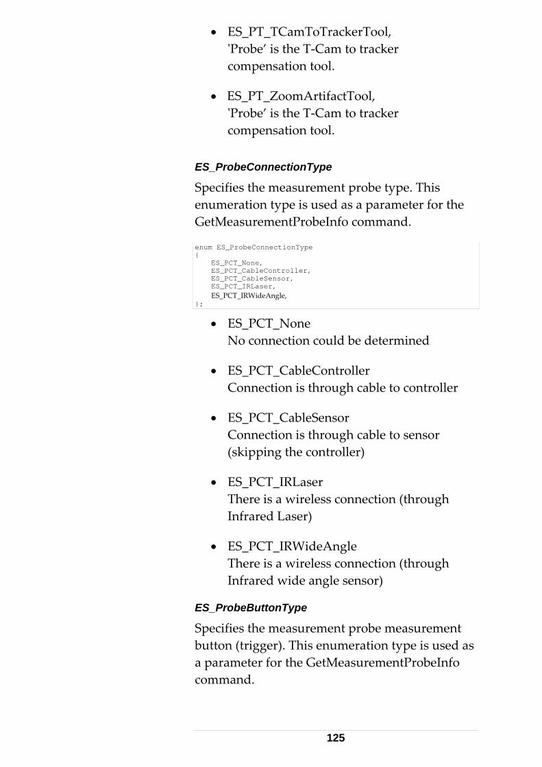
• ES_PT_TCamToTrackerTool, 'Probe’ is the T-Cam to tracker compensation tool.
• ES_PT_ZoomArtifactTool, 'Probe’ is the T-Cam to tracker compensation tool.
ES_ProbeConnectionType
Specifies the measurement probe type. This enumeration type is used as a parameter for the GetMeasurementProbeInfo command.
enum ES_ProbeConnectionType { ES_PCT_None, ES_PCT_CableController, ES_PCT_CableSensor, ES_PCT_IRLaser, ES_PCT_IRWideAngle, };
• ES_PCT_None No connection could be determined
• ES_PCT_CableController Connection is through cable to controller
• ES_PCT_CableSensor Connection is through cable to sensor (skipping the controller)
• ES_PCT_IRLaser There is a wireless connection (through Infrared Laser)
• ES_PCT_IRWideAngle There is a wireless connection (through Infrared wide angle sensor)
ES_ProbeButtonType
Specifies the measurement probe measurement button (trigger). This enumeration type is used as a parameter for the GetMeasurementProbeInfo command.
125

enum ES_ProbeButtonType { ES_PBT_None, ES_PBT_Measurement, };
• ES_PBT_None The probe is not equipped with a measurement button.
• ES_PBT_Measurement The probe is equipped with a measurement button.
ES_TipType
Specifies the measurement tip type. This enumeration type is used as a parameter for the GetTipAdapters command. Note: There exist alternate terms for 'Tip'. Some talk of 'Stylus'.
enum ES_TipType { ES_TT_None, ES_TT_Fixed, ES_TT_Scanner, ES_TT_TouchTrigger, };
• ES_TT_None Tip type is undefined or could not be determined.
• ES_TT_Fixed Tip tip-type is a fixed standard tip.
• ES_TT_Scanner Tip ‘tip’ type is a scanner. I.e. a ‘virtual tip’.
• ES_TT_TouchTrigger Tip tip-type is equipped with a touch-trigger.
ES_ClockTransition
Specifies the trigger clock transition. This enumeration type is used as a parameter for the Get/SetExternTriggerParams command (ExternTriggerParamsT sub-structure)
126
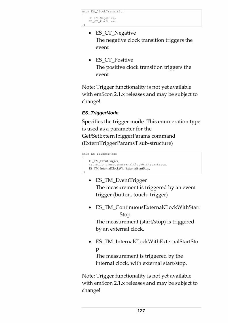
enum ES_ClockTransition { ES_CT_Negative, ES_CT_Positive, };
• ES_CT_Negative The negative clock transition triggers the event
• ES_CT_Positive The positive clock transition triggers the event
Note: Trigger functionality is not yet available with emScon 2.1.x releases and may be subject to change!
ES_TriggerMode
Specifies the trigger mode. This enumeration type is used as a parameter for the Get/SetExternTriggerParams command (ExternTriggerParamsT sub-structure)
enum ES_TriggerMode { ES_TM_EventTrigger, ES_TM_ContinuousExternalClockWithStartStop, ES_TM_InternalClockWithExternalStartStop, };
• ES_TM_EventTrigger The measurement is triggered by an event trigger (button, touch- trigger)
• ES_TM_ContinuousExternalClockWithStart Stop The measurement (start/stop) is triggered by an external clock.
• ES_TM_InternalClockWithExternalStartStop The measurement is triggered by the internal clock, with external start/stop.
Note: Trigger functionality is not yet available with emScon 2.1.x releases and may be subject to change!
127

ES_TriggerStartSignal
Specifies the level of the trigger start signal. This enumeration type is used as a parameter for the Get/SetExternTriggerParams command (ExternTriggerParamsT sub-structure)
enum ES_TriggerStartSignal { ES_TSS_Low, ES_TSS_High, };
• ES_TSS_Low The trigger start signal is of low level.
• ES_TSS_High The trigger start signal is of high level.
Note: Trigger functionality is not yet available with emScon 2.1.x releases and may be subject to change! ES_SystemParameter
Specifies the value to be addressed by the ES_C_Set/GetLongSystemParameter command.
enum ES_SystemParameter { ES_SP_KeepLastPositionFlag , ES_SP_WeatherMonitorSetting, ES_SP_ShowAll6DMeasurements, ES_SP_LaserPointerCaptureBeam, ES_SP_DisplayReflectorPosition, ES_SP_ProbeConfig_Button, ES_SP_ProbeConfig_ButtonEvent, ES_SP_ProbeConfig_Tip, ES_SP_ProbeConfig_SoundVolume, };
• ES_SP_KeepLastPositionFlag Param value: 0 = OFF; 1 = ON. Important: Enabling the ‘KeepLastPosition’ flag is compulsory for 6D Measurement Modes. Otherwise the Probe will not be recognized (If beam catched at zero position). Alternativley, this setting also can be controlled through the SetSystemSettings command.
128
• ES_SP_WeatherMonitorSetting Parameter value: see ES_WeatherMonitorStatus. Alternativley, this setting also can be controlled through the SetSystemSettings command.
• ES_SP_ShowAll6DMeasurements Parameter value: 0 = Only show data if 6D rotation status is OK (default); 1 = Show always.
• ES_SP_LaserPointerCaptureBeam Allows to control the behavior of the 'PointLaser' command if the beam is being sent very close to a reflector. In this situation, it is not always desired that the laser beam locks on to the reflector. Parameter value: 0 = Beam catch OFF; 1 = Beam catch ON (default).
• ES_SP_DisplayReflectorPosition Parameter value: 0 = Disable Reflector Position Tracking (default); 1 = Enable Tracking. This setting also can be controlled through the SetSystemSettings command.
• ES_SP_ProbeConfig_Button Configures the behavior of the probe- buttons. Parameter values: see enum ES_ProbeConfigButton
• ES_SP_ProbeConfig_ButtonEvent Enables/disables events throwing on using the probe buttons. Parameter values: see enum ES_ProbeButtonEvent
• ES_SP_ProbeConfig_Tip Configure whether 6Dof measurements are allowed without a mounted Tip or not. Parameter values: enum ES_ProbeConfigTip
• ES_SP_ProbeConfig_SoundVolume Parameter values: volume as long, 0: No
129
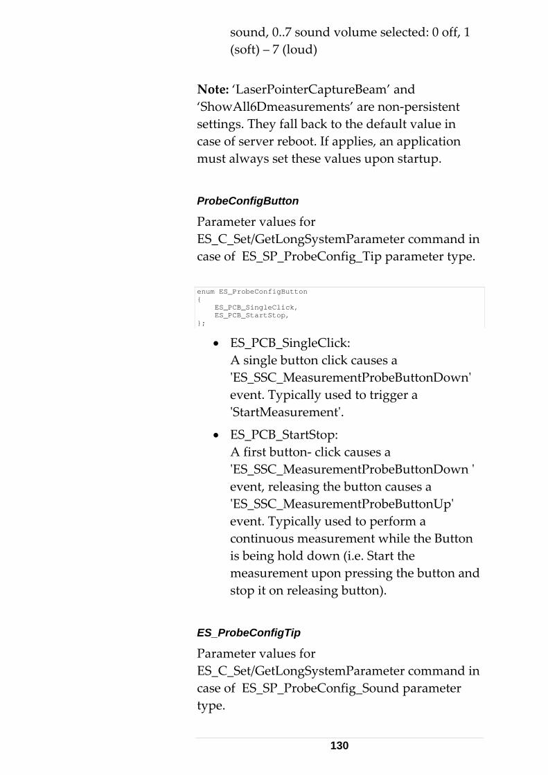
sound, 0..7 sound volume selected: 0 off, 1 (soft) – 7 (loud)
Note: ‘LaserPointerCaptureBeam’ and ‘ShowAll6Dmeasurements’ are non-persistent settings. They fall back to the default value in case of server reboot. If applies, an application must always set these values upon startup.
ProbeConfigButton
Parameter values for ES_C_Set/GetLongSystemParameter command in case of ES_SP_ProbeConfig_Tip parameter type.
enum ES_ProbeConfigButton { ES_PCB_SingleClick, ES_PCB_StartStop, };
• ES_PCB_SingleClick: A single button click causes a 'ES_SSC_MeasurementProbeButtonDown' event. Typically used to trigger a 'StartMeasurement'.
• ES_PCB_StartStop: A first button- click causes a 'ES_SSC_MeasurementProbeButtonDown ' event, releasing the button causes a 'ES_SSC_MeasurementProbeButtonUp' event. Typically used to perform a continuous measurement while the Button is being hold down (i.e. Start the measurement upon pressing the button and stop it on releasing button).
ES_ProbeConfigTip
Parameter values for ES_C_Set/GetLongSystemParameter command in case of ES_SP_ProbeConfig_Sound parameter type.
130

enum ES_ProbeConfigTip { ES_PCT_OnlyWithTip, ES_PCT_NoTipAllowed, };
• ES_PCT_OnlyWithTip: Probe requires a Tip attached
• ES_PCT_NoTipAllowed: No tip required (Scanner- probes)
ES_ProbeButtonEvent
ES_C_Set/GetLongSystemParameter command in case of ES_SP_ProbeConfig_ButtonEvent parameter type.
ES_API enum ES_ProbeButtonEvent { ES_PBE_DisableEvents, ES_PBE_EnableEvents, };
• ES_PBE_DisableEvents: no button events are sent
• ES_PBE_EnableEvents: server sends button events
ES_MeasurementStatusInfo
The values of this enum can be used to identify/mask each individual bit of the long parameter delivered by the command ES_C_GetMeasurementStatusInfo. Hence the power of 2 of every value. The meaning of the values should be self-explaining according to their symbol-names. See description of command ES_C_GetMeasurementStatusInfo for further information.
131

enum ES_MeasurementStatusInfo { ES_MSI_Unknown = 0, ES_MSI_TrackerFound = 1, ES_MSI_TrackerCompensationFound = 2, ES_MSI_ADMFound = 4, ES_MSI_ADMCompensationFound = 8, ES_MSI_MeasurementCameraFound = 16, ES_MSI_InternalCameraParamsOK = 32, ES_MSI_CameraToTrackerParamsFound = 64, ES_MSI_MeasurementProbeFound = 128, ES_MSI_ProbeParamsFound = 256, ES_MSI_MeasurementTipFound = 512, ES_MSI_TipParamsFound = 1024, ES_MSI_ReflectorFound = 2048, ES_MSI_InFace1 = 4096, };
132

3.4 Data Structures This section describes all data structures defined in ES_C_API_Def.h. The data structures describe the 'layout' of the data packets (byte arrays) to be transmitted over the TCP/IP network. The structures are required to construct and send data packets, to mask incoming data packets in order to recognize their type and to interpret their contents.
Note the 4-Byte alignment prerequisite for the Tracker Server and the client. See #pragma pack (push, 4) in file ES_C_API_Def.h. The 'pragma pack' is a Microsoft specific C-languageextension. A 4-Byte alignment may be different for other C/C++ compilers. No change of layout ( # of bytes and alignment for each member) is permitted, during translation of these structures to other languages.
There is a short general description for each type. All members are not described in detail. Data members are often self- explanatory, while enumeration-type members have been described under Enumeration Types. Struct variable descriptions are provided only where necessary.
Parameters are always in current units and coordinate system / CS-type (where applicable) – unless specified otherwise.
3.4.1 Basic Data Structures This section describes those data structures that are not directly exchanged as packets. They are used as sub-structures to compose the real 'Packet' data types.
133

PacketHeaderT struct PacketHeaderT { long lPacketSize; enum ES_DataType type; };
This basic structure is a part of all data blocks transmitted over the TCP/IP network. The lPacketSize has been introduced for programmer's convenience. The value of the data structure contains the size (in Bytes) of received packets. Upon sending packets, this value is ignored. It is good programming practice to initialize this value with the correct size, even on sending data.
New for emScon V2.0 and up: The strike-through statement above (which was valid up to emScon 1.5 servers) is no longer true. The lPacketSize value is no longer ignored. It is compulsory to correctly initialize this value. Otherwise, command calls will mostly fail. Note that due to this change, existing V1.2 / V1.5 emScon C- clients, who did not initialize these length variables, will fail with emScon servers newer than V2.0. Such client applications need to be fixed at source level.
C- programmers have the sizeof() operator. This is inappropriate in other languages, to determine the size of data structures. ReturnDataT struct ReturnDataT { struct PacketHeaderT packetHeader; enum ES_ResultStatus status; };
This basic structure is part of all result data blocks. It comprises a PacketHeaderT and a ES_ResultStatus.
134
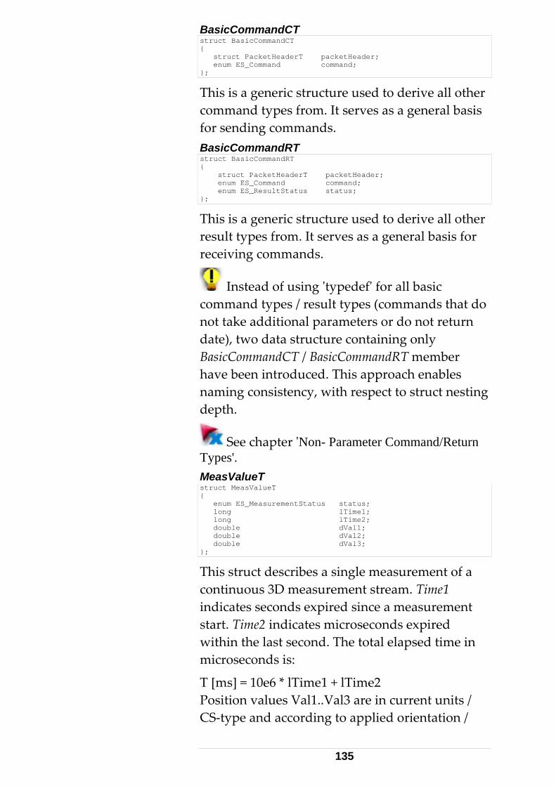
BasicCommandCT struct BasicCommandCT { struct PacketHeaderT packetHeader; enum ES_Command command; };
This is a generic structure used to derive all other command types from. It serves as a general basis for sending commands. BasicCommandRT struct BasicCommandRT { struct PacketHeaderT packetHeader; enum ES_Command command; enum ES_ResultStatus status; };
This is a generic structure used to derive all other result types from. It serves as a general basis for receiving commands.
Instead of using 'typedef' for all basic command types / result types (commands that do not take additional parameters or do not return date), two data structure containing only BasicCommandCT / BasicCommandRT member have been introduced. This approach enables naming consistency, with respect to struct nesting depth.
See chapter 'Non- Parameter Command/Return Types'. MeasValueT struct MeasValueT { enum ES_MeasurementStatus status; long lTime1; long lTime2; double dVal1; double dVal2; double dVal3; };
This struct describes a single measurement of a continuous 3D measurement stream. Time1 indicates seconds expired since a measurement start. Time2 indicates microseconds expired within the last second. The total elapsed time in microseconds is:
T [ms] = 10e6 * lTime1 + lTime2 Position values Val1..Val3 are in current units /CS-type and according to ap
plied orientation /
135

transformation parameters. MeasValue2T struct MeasValue2T { enum ES_MeasurementStatus status; long lTime1; long lTime2; double dVal1; double dVal2; double dVal3; double dAprioriStdDev1; double dAprioriStdDev2; double dAprioriStdDev3; double dAprioriStdDevTotal; double dAprioriCovar12; double dAprioriCovar13; double dAprioriCovar23; };
This struct describes a single measurement of a continuous 3D measurement stream in casestatistical mode is set to ‘extended’. Principallthe same as MeasValueT, but with statistic information in addition. Position valuestatistic parameters are in cu
the y
s and rrent units / CS-type
ee command 'SetStatisticMode' and description eT' above, for details.
and according to applied orientation / transformation parameters.
Sof struct 'MeasValu
136
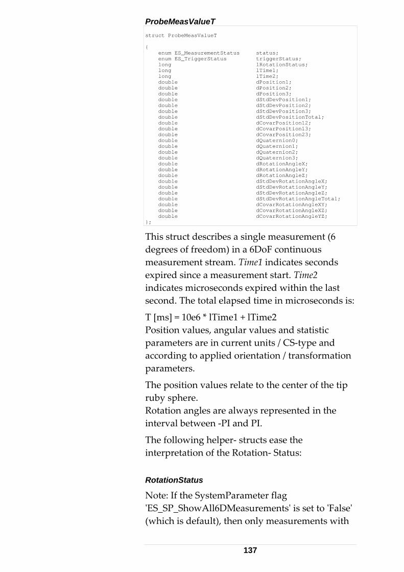
ProbeMeasValueT struct ProbeMeasValueT { enum ES_MeasurementStatus status; enum ES_TriggerStatus triggerStatus; long lRotationStatus; long lTime1; long lTime2; double dPosition1; double dPosition2; double dPosition3; double dStdDevPosition1; double dStdDevPosition2; double dStdDevPosition3; double dStdDevPositionTotal; double dCovarPosition12; double dCovarPosition13; double dCovarPosition23; double dQuaternion0; double dQuaternion1; double dQuaternion2; double dQuaternion3; double dRotationAngleX; double dRotationAngleY; double dRotationAngleZ; double dStdDevRotationAngleX; double dStdDevRotationAngleY; double dStdDevRotationAngleZ; double dStdDevRotationAngleTotal; double dCovarRotationAngleXY; double dCovarRotationAngleXZ; double dCovarRotationAngleYZ; };
This struct describes a single measurement (6 degrees of freedom) in a 6DoF continuous measurement stream. Time1 indicates seconds expired since a measurement start. Time2 indicates microseconds expired within the last second. The total elapsed time in microseconds is
T [ms] = 10e6 * lTime1 + lTime2 Position values, angular values and statistiparameters are in current units / CS-type and according to applied orientation / transformation parameters.
The position values relate to the center of the ruby sphere. Rotation angles are always represented in the interval between -PI and PI.
The following helper- structs ease the in
:
c
tip
terpretation of the Rotation- Status: RotationStatus
Note: If the SystemParameter flag 'ES_SP_ShowAll6DMeasurements' is set to 'False' (which is default), then only measurements with
137
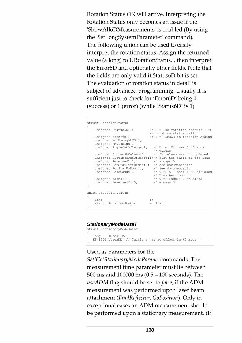
Rotation Status OK will arrive. Interpreting the
meter' command).
erpret
rotation status in detail is ming. Usually it is
6D’ being 0 uccess) or 1 (error) (while ‘Status6D’ is 1).
Rotation Status only becomes an issue if the 'ShowAll6DMeasurements' is enabled (By using the 'SetLongSystemParaThe following union can be used to easily interpret the rotation status: Assign the returned value (a long) to URotationStatus.l, then intthe Error6D and optionally other fields. No
it is set. te that
the fields are only valid if Status6D bThe evaluation ofsubject of advanced programsufficient just to check for ‘Error(s struct RotationStatus { unsigned Status6D:1; // 0 => no rotation status; 1 => // rotation status valid unsigned Error6D:1; // 1 => ERROR in rotation status unsigned NotEnoughLED:1; unsigned RMSToHigh:1; unsigned AngleOutOfRange:1; // Hz or Vt (see RotStatus // values) unsigned Frozen6DValues:1; // 6D values are not updated ! unsigned DistanceOutOfRange:1;// dist too short or too long unsigned Reserved1:1; // always 0 unsigned RotStatLeftRight:3; // see documentation unsigned RotStatUpDown:3; // see documentation unsigned GoodGauge:2; // 0 => All bad; 1 => 33% good // 2 => 66% good ... unsigned Face2:1; // 0 => Face1; 1 => Face2 unsigned Reserved2:15; // always 0 }; union URotationStatus { long l; struct RotationStatus rotStat; };
StationaryModeDataT struct StationaryModeDataT { long lMeasTime; ES_BOOL bUseADM; // Caution: has no effect in 6D mode ! };
Used as parameters for the Set/GetStationaryModeParams commands. The measurement time parameter must lie betwee500 ms and 100000 ms (0.5 – 100 seconu
n ds). The
seADM flag should be set to false, if the ADM measurement was performed upon laser beam attachment (FindReflector, GoPosition). Only in exceptional cases an ADM measurement should be performed upon a stationary measurement. (If
138

the beam always remains attached to the same e- gap between
or hours).
ll be ignored for
taT ruct ContinuousTimeModeDataT
reflector and there is a major timmeasurements (several minutes
Note that the useADM flag has no effect for 6DOF measurement modes and withese modes, regardless whether true or false. Note: The ‘bUseADM’ Flag only applies to 3D measurement modes and has no effect to 6D modes. It can be ignored in 6D cases. ContinuousTimeModeDast{ long lTimeSeparation; long lNumberOfPoints; ES_BOOL bUseRegion; enum ES_RegionType regionType; };
Used as parameters for the Set/GetContinuousTimeModeParams commands. A
ro means 'infinite' (in lNumberOfPoints value of zethis case, the measurement must be stopped explicitly with a StopMeasurement command). Time separation is in milliseconds and can vary between 1..99999 ms. ContinuousDistanceModeDataT struct ContinuousDistanceModeDataT { double dSpatialDistance; long lNumberOfPoints; ES_BOOL bUseRegion; enum ES_RegionType regionType; };
Used as parameters for the SA
et/GetContinuousDistanceModeParams commands. lNumberOfPoints value of zero means 'infinite'
tly). Rather than based riteria, a distance criteria is ngth- unit. Note: One
gle measurement will be preformed upon easurements are not
ands SetBox- /
(must be stopped explicion a time- separation cused. It is in current lesinStartMeasurement. Further mtaken until the reflector is being moved. A region can be applied to limit the 'sensitive' measurement space. See comm
139

SetSphereRegionParams for region definiti SphereCestruct SphereCenterModeDataT
on.
nterModeDataT { double dSpatialDistance; long lNumberOfPoints; ES_BOOL bFixRadius; double dRadius; };
Used as parameters for the eParams commands. A
of zero means 'infinite' d explicitly).
adius are in current length-
inuous distance
leCenterModeDataT
Set/GetSphereCenterModlNumberOfPoints value(must be stoppeSpatial distance and Runit. The radius can be left variable (to be calculated by the fit- routine), or fixed, if it is known. Same trigger criteria as with Contmode. CircleCenterModeDataT struct Circ{ double dSpatialDistance; long lNumberOfPoints; ES_BOOL bFixRadius; double dRadius; };
Used for parameters Set/GetCircleCenterModeParams commands. A
f zero means 'infinite' itly).
it. tial distance and Radius are in current length-
ariable (to be
lNumberOfPoints value o(must be stopped explicRadius is in current length- unSpaunit. The radius can be left vcalculated by the fit- routine), or fixed, if it is known. Same trigger criteria as with Continuous distance mode.
140

GridModeDataT struct GridModeDataT { double dVal1; double dVal2; double dVal3; long lNumberOfPoints; ES_BOOL bUseRegion; enum ES_RegionType regionType; };
Used as parameters for the Set/GetGridModeParams commands. Tdescribe the grid size in the CS. Position values are in current units / CS-type. A lNvalue of zero means 'infinite' (must be stoppexplicitly). A region can be applied to limit the 'senmeasurement space. See commands 'SetBox- SetSphereRegionParams' for region definition. SearchParamsDataT struct SearchParamsDataT
he 3 values
umberOfPoints ed
sitive' /
{ double dSearchRadius; double lTimeOut; };
Used for parameters of Set/GetSearchParams commands. The search process is aborted upon one or the other of the two criterias is reached. TimeOut is in milliseconds. There is a minimuvalue of 10’000 ms (10 Seconds). Note: this minimum value was 2500 ms in previous emScon versions and has been increto 10000 for EmScon from Version 2.0! SearchRadius is in current units. The timeout parameter will interrupt the search if it takes too
m
ased
ig search radius (if no reflector ). The Search
h units and must lie
was 1.0 m in d
long due to a too bfound within the specified timeRadius in current lengtbetween 0 and 0.5 meters. (Caution with small or even zero radius and / or small timeOut: Too small value may cause the search process to fail. Note: the maximum radius value previous emScon versions and has been reduceto 0.5 m for emScon Version! Large search radii result in extended search
141

times, unless time is limited to a reasonable value. Typical values are 0.05 m for the radius and 30’000 ms for timeout. AdmParamsDataT struct AdmParamsDataT { double dTargetStabilityTolerance; double lRetryTimeFrame; double lNumberOfRetrys; };
Used for parameters for the Set/GetAdmParams
n 0.005
ange these parameters if ork ironment (vibrations). w
prec
struct
commands. RetryTimeFrame is in milliseconds in the range between 500 and 5000. TargetStabilityTolerance is a distance parameter and is in current length- units. TargetStabilityTolerance must lie betweeand 0.1 Millimeter. Leave this value as low as possible! (Default is 0.005). The SetAdmParams command should be used with caution. Only chw ing in an unstable envLo ering the stability tolerance results in loss of
ision!
SystemSettingsDataT SystemSettingsDataT
{ enum ES_WeatherMonitorStatus weatherMonitor; ES_BOOL bApplyTransformationParams; ES_BOOL bApplyStationOrientationParams; ES_BOOL bKeepLastPosition; ES_BOOL bSendUnsolicitedMessages; ES_BOOL bSendReflectorPositionData; ES_BOOL bTryMeasurementMode; ES_BOOL bHasNivel; ES_BOOL bHasVideoCamera; };
Usedcommands. The system settings are a collection of variothe e
• onitorStatus cription on
•
for parameters of Set/Get SystemSettings
us 'properties' to control certain behavior of mScon system :
WeatherMIndicates the WM status. See desenum ES_WeatherMonitorStatus
bApplyTransformationParams If this flag is set to false, the System does not
142

transform the measurements into a user-specified coordinate system. If set to true, transformation as per transformation parameters is applied. If set to false, the default transform0, 0, 1}, regardless of the current values set with SetTransformationParams command. Transformations also apply to the positioning commands (such as GoPosition)and to part of the Input/Output filters (BoxSphere)
bApplyStationOrientationParams If this flag is set to true, the System uses thgiven orientation parameters. If set to falsethe default stat0, 0, 0, 0, 0}, regardless of the current valuesset with the SetStationOrientationParams command. Orientations also apply to the position
bKeepLastPosition If this flag is set to true and the laser beambroken, it does not leave the current posiThis allows to 'catch' the beam again, then
ation will be used {0, 0, 0, 0,
,
• e ,
ion orientation will be used {0,
ing commands (such as GoPosition).
• is
tion.
placing the reflector to a stable position. The Aand – if success- sets the measured distance as the new interferometer distance. From then on, it is possible to recover measuring without hbIf eam is disabled (mispImflMrecognized (If beam catched at zero position).
DM then tries to perform a measurement
aving to go back to the BirdBath on beam roken events. the flag is set to false, the b
irror points down). If an Overview Camera installed, the sensor drives into the camera osition.
portant: Enabling the ‘KeepLastPosition’ ag is compulsory for 6D Measurement odes. Otherwise the Probe will not be
143
• s all
they occur. This flag er
- change hese events should be
• flector / Probe
sends
ed measurement is in
hey can be used to view the
re of
details.
ode
ature and therefore
• A
or system
• flag
bSendUnsolicitedMessages If this flag is set to true, the system senderror messages as should always be true. Otherwise neitherror events nor system statusevents will be issued. Tsuppressed only in real special situations.
bSendReflectorPositionData If this flag is set to true and a reis locked on by the tracker, the systemthe current reflector position (max. 3 measurements per second). These are issueven when no continuousprogress. TReflector/probe movement on applications with graphic representation of reflector movement. Do not regard the position valuesas accurate measurements. They alimited accuracy! See structs 'ReflectorPosResultT' and 'ProbePosResultT' for
• bTryMeasurementMIf this flag is set to true, the system delivers all results in the try mode. This is a Leica internal feundocumented. It can be ignored by application programmers. The effect is just that – if set to true – the value is 'echoed' with each measurement.
bHasNivel hardware Configuration issue. This flag
tells the system that a Nivel20 sensor is attached. Measurements with the sensor are now possible. The system cannot automatically detect whether a Nivel sensis attached. Hence you must tell it theby enabling this flag.
bHasVideoCamera A hardware Configuration issue. This
144
tells the system, that an Overview present. If your system is equipped with an overcamera, it is recommended to always havingchecked this flag (even when the cametemporarily removed). Otherwise, leave it always unchecked (= default).
Camera is
view
ra is
In the meantime there exist different types of overview cameras that differ in internal parameters (focus distance, CCD chip size). Older emScon versions were not able to detect whether an overview camera was mounted or not, not to speak of type recognition (indeed it was the overviewcamera hardware that did not support typerecognition). For that reason, the flag 'HasVideoCamera' was originally introduced. Thus, the user had to 'tell' the system when an overview camera was mounted. Newer EmScon versions (2.0 and up) are able to detect the camera type automatically. Hence, this flag theoretically
solete. However, currently the y when the abled.
an overview
ot detect the correct camera type and use
lt) parameters. ng parameters do not cause
. The only effect will be that
the
has become obcamera type is recognized onl'hHasVideoCamera' flag is enIf your system is equipped withcamera, it is highly recommended to always having this flag checked (default is unchecked). Otherwise, the system may n
wrong (defauHowever, wroany fatal failuresthe 'Find Reflector' feature by clicking to the live video image by mouse pointer will move the tracker inaccurately (typically, the tracker will move double or half the amount of 'clicked' distance).
145
SystemUnitsDataT struct SystemUnitsDataT { enum ES_LengthUnit lenUnitType; enum ES_AngleUnit angUnitType; enum ES_TemperatureUnit tempUnitType; enum ES_PressureUnit pressUnitType; enum ES_HumidityUnit humUnitType; };
Use mands. ee related enums – they explain themselves.
d for parameters of Set/GetUnits comS
EnvironmentDataT struct EnvironmentDataT { double dTemperature; double dPressure; double dHumidity; };
Used for parameters of Set/Gecommands. The SetEnvironmentParams commmainly applies when no weather monitor is available, or when disabled by the bUseWeatherMonitor setting. Otherwise, these
tEnvironmentParams and
parameters are updated implicitly and the current values can be retrieved with the GetEnvironmentParams. See also description of enum 'ES_WeatherMonitorStatus'.
See chapter 'Working Conditions'. RefractionDataT struct RefractionDataT { double dIfmRefractionIndex; double dAdmRefractionIndex; };
Used for parameters of Set/GetRefractionParams commands. See also description of enum
S_WeatherMonitorStatus'. dvanced and special used in combination with
nitorStatus mode Only'. See description there.
ion should not explicitly set hey are set indirectly by
f no
mode 'ES_WMS_ReadAndCalculateRefractions'
'EThis is a command for ausage. It should only be the WeatherMo'ES_WMS_Read
Normal applicatrefraction parameters. Tusing the SetEnvironmentParams command (iweather monitor available), or by selecting the
146

(if a WM is connected).
Under certain conditions, the refraction parameters are updated (set) implicitly on setting
rameters. See description of onitorStatus'.
new environment paenum 'ES_WeatherM
See chapter 'Working Conditions'.
tionOrientationDataT Stastruct StationOrientationDataT { double dVal1; double dVal2; double dVal3; double dRot1; double dRot2; double dRot3; };
Used as parameters for Set/GetStationOrientationParams commands.
rent units and CS-type. These abled/disabled through the tationOrientationParams.
nsformationDataT
Values are in cursettings can be ensystem flag bUseS
Trastruct TransformationDataT { double dVal1; double dVal2; double dVal3; double dRot1; double dRot2; double dRot3; double dScale; };
Used as parameters for Set/GetTransformationParams commands. Vaare in current units and CS-type. These settincan be enableb
lues gs
d/disabled through the system flag UseLocalTransformationMode.
BoxRegionDataT struct BoxRegionDataT{ double dP1Val1; double dP1Val2; double dP1Val3; double dP2Val1; double dP2Val2; double dP2Val3; };
Used for parameters of Scommands. The parameters describe two
et/GetBoxRegionParams
147
diagonal points of a box. Values are in current units and C
ccording to active transformation settings). These settings only apply if the bUseRegion flathe appropriate continuous measurement structu
S-type (but not a
g in
re is enabled, together with the 'Box' egion type. r
SphereRegionDataT struct SphereRegionDataT { double dVal1; double dVal2; double dVal3; double dRadius; };
Used for parameters of Set/GetSphereRegionParamscommands. The parameters describe center point
nd radius of a sphere. s and (apart from e and according to
aValues are in current unitRadius) in current CS-typapplied transformation settings.
These settings only apply if the bUseRegion us measurement
Sphere' region
ersionNumberT
flag in the appropriate continuostructure is enabled, together with 'type.
ESVstruct ESVersionNumberT { int iMajorVersionNumber; int iMinorVersionNumber; int iBuildNumber; };
Used for one of the parametersGetSystemStatus command. Contains versionof the currently installed tracker server software
of the info
.
148
TransformationInputDataT aT struct TransformationInputDat
{ enum ES_TransResultType resultType; double dTransVal1; double dTransVal2; double dTransVal3; double dRotVal1; double dRotVal2; double dRotVal3; double dScale; double dTransStdVal1; double dTransStdVal2; double dTransStdVal3; double dRotStdVal1; double dRotStdVal2; double dRotStdVal3; double dScaleStd; };
Used for parameters of the Set/GetTransformationInputParams command. Used in order to specify (Fixing, Weighttransformation result values
ing) .
tion
or details see Section 9.2 .
meters, use values as er 'Constants'.
Values are in current units and (apart from Radius) in current CS-type (No transformaapplies).
F
For the StdDev paraspecified in chapt
TransformationPointT struct TransformationPointT { double dVal1; double dVal2; double dVal3; double dStd1; double dStd2; double dStd3; double dCov12; double dCov13; double dCov23; };
It is used as a sub- structure for the AddNominal ommands.
gs.
onstants'.
/AddActualTransformationPoint cValues are in current units and CS-type and according to applied transformation settings only in case of actual points. Nominal points are not influenced by transformation settinFor details see Section 9.2 .
For the StdDev parameters, use values asspecified in chapter 'C
149

CameraParamsDataT struct CameraParamsDataT { int iContrast; int iBrightness; int iSaturation; };
U for parameters of the Set/GetCameraParams sedcommand. Values of Contrast/Brightness range from 0 to 256.
to ze
a Structures eal data blocks
P network between the
Saturation is currently not used and must be set ro.
3.4.2 Packet DatThese data types describe the rexchanged over the TCP/ITracker Server and the application PC. There are9 main types of packets (see enum 'ES_DataType'). The structures of ES_DT_Command- type packets differ for different commands.
All packet types contain (directly or througanother sub-structure such as ReturnDataT, BasicCommandCT or BasicCommandRT) a sub-structure of type PacketHeaderT with the size and type of the packet.
h
•
er.
type packets, command, error and measurements always contain a status parameter.
ErrorResponseT struct ErrorResponseT
Command type packets (apart from a certain number of parameters), always contain an ES_Command command type paramet
• Return
{ struct PacketHeaderT packetHeader; enum ES_Command command; enum ES_ResultStatus status; };
This receive-only structure ES_DT_Error packet type describes the packet size and type. It
150

contains a standard packet header and a return
ten set to s are often occur e not a reaction to a
roken' error. Such d is obviously
status, ES_ResultStatus, or a tracker error number.
The 'command' parameter is ofES_C_Unknown since error'unsolicited', that is, they arcommand. Consider a 'beam ban event can happen at any time annot caused by a command.
See 8. Appendix at the bottom of this
nknown
document.
The command parameter is set to ES_C_Uunless the error was caused by particular command.
SingleMeasResultT struct SingleMeasResultT { struct ReturnDataT packetInfo; enum ES_MeasMode measMode; ES_BOOL bIsTryMode; double dVal1; double dVal2; double dVal3; double dStd1; double dStd2; double dStd3; double dStdTotal; double dPointingError1; double dPointingError2; double dPointingError3; double dAprioriStd1; double dAprioriStd2; double dAprioriStd3; double dAprioriStdTotal; double dTemperature; double dPressure; double dHumidity; };
This receive-only structure describes the ES_DT_SingleMeasResult packet type. Apart from the standard ReturnDataT structure, it containsdata specific
to a single tracker 3D measurement.
addition to the 3 coordinate values, there is statistical information such as standard deviations (a posteriori and a priori) and pointing errors. The environmental values are those currently valid to the system (either those explicitly set by SetEnvironmentParams, or those last implicitly updated by the weather monitor).
In
151

The flag bIsTryMode is set if system is in 'Try common users. Mode'. This is not relevant for
The format of measurements, statistical ental values depend
nts and statistical rding current CS-
/ transformation
informations and environmon current units. Measuremeinformation in addition are accotype and applied orientation parameters.
SingleMeasResult2T struct SingleMeasResult2T { struct ReturnDataT packetInfo; enum ES_MeasMode measMode; ES_BOOL bIsTryMode; double dVal1; double dVal2; double dVal3; double dStdDev1; double dStdDev2; double dStdDev3; double dStdDevTotal; double dCovar12; double dCovar13; double dCovar23; double dPointingErrorH; double dPointingErrorV; double dPointingErrorD; double dAprioriStdDev1; double dAprioriStdDev2; double dAprioriStdDev3; double dAprioriStdDevTotal; double dAprioriCovar12; double dAprioriCovar13; double dAprioriCovar23; double dTemperature; double dPressure; double dHumidity; };
This receive-only structure describes the ES_DT_SingleMeasResult2 packet type in case of extended statistical mode. Use this variant if points to be used as input for the Transformation outine.
bIsTryMode is set, if system is in 'Try elevant for common users.
'.
rThe flag Mode'. This is not r
See also command 'SetStatisticMode
The format of measurements, statistical tal values depend
ents and statistical rent CS-
informations and environmenon current units. Measureminformation in addition are according curtype and applied orientation / transformation parameters.
152

MultiMeasResultT struct MultiMeasResultT { struct ReturnDataT packetInfo; long lNumberOfResults; enum ES_MeasMode measMode; ES_BOOL bIsTryMode; double dTemperature; double dPressure; double dHumidity; struct MeasValueT data[1]; };
This receive-only structure describes the ES_ here a continuous stream of packets is received during a
d t.
' umberOfResults parameter
identifies the number of array elements, and the
DT_MultiMeasResult packet type, w
continuous measurement. A packet consists of the single measurement anan array of MeasValueT parameters attached to iThe MultiMeasResultT structure only contains (covers) the first element of this array (a 'pointerto the array). The lN
remaining elements can be iterated from data [0] … data [lNumberOfResults - 1].
C-arrays are always zero-based.
This structurm
e only covers the header of a multi-easurement packet. Measurement mode and
meters are common for the e flag bIsTryMode is
ot relevant
environmental parabody (measurement array). Thset if system is in Try Mode. This is nfor common users.
The format of measurements, statistical
t CS-
informations and environmental values depend on current units. Measurements and statistical information in addition are according currentype and applied orientation / transformation parameters.
153

MultiMeasResult2T struct MultiMeasResult2T { struct ReturnDataT packetInfo; long lNumberOfResults; enum ES_MeasMode measMode; ES_BOOL bIsTryMode; double dTemperature; double dPressure; double dHumidity; struct MeasValue2T data[1]; };
The same as MultiMeasResultT (see above), but to received in case the statistical mode is set
‘extended’.
See also command 'SetStatisticMode'. ProbeStationaryResultT struct ProbeStationaryResultT { struct ReturnDataT packetInfo; enum ES_MeasMode measMode; ES_BOOL bIsTryMode; enum ES_TriggerStatus triggerStatus; long lRotationStatus; long iInternalProbeId; int iFieldNumber; enum ES_MeasurementTipStatus tipStatus; long iInternalTipAdapterId; long iTipAdapterInterface; double dPosition1; double dPosition2; double dPosition3; double dStdDevPosition1; double dStdDevPosition2; double dStdDevPosition3; double dStdDevPositionTotal; double dCovarPosition12; double dCovarPosition13; double dCovarPosition23; double dAprioriStdDevPosition1; double dAprioriStdDevPosition2; double dAprioriStdDevPosition3; double dAprioriStdDevPositionTotal; double dAprioriCovarPosition12; double dAprioriCovarPosition13; double dAprioriCovarPosition23; double dQuaternion0; double dQuaternion1; double dQuaternion2; double dQuaternion3; double dRotationAngleX; double dRotationAngleY; double dRotationAngleZ; double dStdDevRotationAngleX; double dStdDevRotationAngleY; double dStdDevRotationAngleZ; double dStdDevRotationAngleTotal; double dCovarRotationAngleXY; double dCovarRotationAngleXZ; double dCovarRotationAngleYZ; double dAprioriStdDevRotationAngleX; double dAprioriStdDevRotationAngleY; double dAprioriStdDevRotationAngleZ; double dAprioriStdDevRotationAngleTotal; double dAprioriCovarRotationAngleXY; double dAprioriCovarRotationAngleXZ; double dAprioriCovarRotationAngleYZ; double dTemperature; double dPressure; double dHumidity; };
This receive-only structure describes the ES_DT_Single6DMeasResult packet type.
154

This structure is used to transmit the result of a 6D stationary measurement. The result depends
e coordinate tation and transformation
Adapter where Tip mounted including its
values relate to the
- Rotation Angles including their accuracy
the
on current length and angle units, thsystem type, orienparameters applied. It contains:
- Status Information
-accuracy
- Probe position. The positioncenter of the tip ruby sphere.
- Probe orientation in two different representations:
- Quaternion or
- Environmental Data
Rotation angles are always represented ininterval between -PI and PI.
Details about RotationStatus: see chapter 'Rotation Status' just following the chapter 'ProbeMeasValueT' Applies only to 6DoF systems. ProbeContinuousResultT struct ProbeContinuousResultT { struct ReturnDataT packetInfo; long lNumberOfResults; enum ES_MeasMode measMode; ES_BOOL bIsTryMode; long iInternalProbeId; int iFieldNumber enum ES_MeasurementTipStatus tipStatus; long iInternalTipAdapterId; long iTipAdapterInterface; double dTemperature; double dPressure; double dHumidity; struct ProbeMeasValueT data[1]; };
This receive-only structure describes the ES_DT_ ContinuousProbeMeasResult packet type. The only
155
difference to an ES_DT_ MultiMeasResult is tarray element types. Applies only to
he 6DoF
systems. NivelResultT struct NivelResultT { struct ReturnDataT packetInfo; enum ES_NivelStatus nivelStatus; double dXTilt; double dYTilt; double dNivelTemperature; };
This receive-only structure describes the ES_DT_NivelResult packet type, which includes
cture and contains data easurement.
s' in chapter 3.3.2 tails about supported
the ReturnDataT struspecific to a Nivel20 m
Refer to chapter 'ES_NivelStatu(enumeration types) for demeasurement ranges.
The format of measurement and environmental values do NOT depend on curreunit settings. Nivel results always arrive in nNivel20 format – milliradiant for X/Y tilt andCelsius for temperature. ReflectorPosResultT struct ReflectorPosResultT
nt ative
{ struct ReturnDataT packetInfo; double dVal1; double dVal2; double dVal3; };
This receive-only structure describes the hese are
a
s can be
current
entation / transformation parameters.
ES_DT_ReflectorPosResult packet type. Treceived whenever the tracker is locked ontoreflector (3 measurements per second). The receipt of these 'measurement'- typeswitched on/off with the systems flag bSendReflectorPositionData. Values are inunits / CS-type and according to appliedori
156

ProbePosResultT struct ProbePosResultT { struct ReturnDataT packetInfo; long lRotationStatus; enum ES_MeasurementTipStatus tipStatus; long iInternalTipAdapterId; long iTipAdapterInterface; double dPosition1; double dPosition2; double dPosition3; double dQuaternion0; double dQuaternion1; double dQuaternion2; double dQuaternion3; double dRotationAngleX; double dRotationAngleY; double dRotationAngleZ; };
The 'Probe' relative to ReflectorPosResult. Values ding to
meters.
The position values relate to the center of the tip
etails about RotationStatus: see chapter otation Status' just following the chapter
are in current units / CS-type and accorapplied orientation / transformation paraThere are some status values in addition. Rotation angles are always represented in the interval between -PI and PI.
ruby sphere. D'R'ProbeMeasValueT' SystemStatusChangeT struct SystemStatusChangeT { struct ReturnDataT packetHeader; enum ES_SystemStatusChange systemStatusChange; };
This receive-only structure describes the ES_DT_SystemStatusChange packet type. These are received when the system status has changed.
See enum 'ES_SystemStatusChange' for supported notification types. ExternTriggerParamsT struct ExternTriggerParamsT { enum ES_ClockTransition clockTransition; enum ES_TriggerMode triggerMode; enum ES_TriggerStartSignal startSignal; long lMinimalTimeDelay; };
Parameters 1..3: See description of appropriate enumeration types.
157

lMinimalTimeDelay: The time delay between trigger event and measurement.
Non- Parameter Command/Return Types
Lists all non- parameter command structures. They are derived from the BasicCommandCT (command-types; client to Server) and the BasicCommandRT (return-types; Server to client).
158

struct InitializeCT { struct BasicCommandCT packetInfo; }; struct InitializeRT { struct BasicCommandRT packetInfo; }; struct ReleaseMotorsCT { struct BasicCommandCT packetInfo; }; struct ReleaseMotorsRT { struct BasicCommandRT packetInfo; }; struct ActivateCameraViewCT { struct BasicCommandCT packetInfo; }; struct ActivateCameraViewRT { struct BasicCommandRT packetInfo; }; struct ParkCT { struct BasicCommandCT packetInfo; }; struct ParkRT { struct BasicCommandRT packetInfo; }; struct GoBirdBathCT { struct BasicCommandCT packetInfo; }; struct GoBirdBathRT { struct BasicCommandRT packetInfo; }; struct GoLastMeasuredPointCT { struct BasicCommandCT packetInfo; }; struct GoLastMeasuredPointRT { struct BasicCommandRT packetInfo; }; struct ChangeFaceCT { struct BasicCommandCT packetInfo; }; struct ChangeFaceRT { struct BasicCommandRT packetInfo; }; struct StartNivelMeasurementCT { struct BasicCommandCT packetInfo; }; struct StartNivelMeasurementRT { struct BasicCommandRT packetInfo; }; struct StartMeasurementCT { struct BasicCommandCT packetInfo; }; struct StartMeasurementRT { struct BasicCommandRT packetInfo;
159
}; struct StopMeasurementCT { struct BasicCommandCT packetInfo; }; struct StopMeasurementRT { struct BasicCommandRT packetInfo; }; struct ExitApplicationCT { struct BasicCommandCT packetInfo; }; struct ExitApplicationRT { struct BasicCommandRT packetInfo; }; struct ClearTransformationNominalPointListCT { struct BasicCommandCT packetInfo; }; struct ClearTransformationNominalPointListRT { struct BasicCommandRT packetInfo; }; struct ClearTransformationActualPointListCT { struct BasicCommandCT packetInfo; }; struct ClearTransformationActualPointListRT { struct BasicCommandRT packetInfo; }; struct ClearDrivePointListCT { struct BasicCommandCT packetInfo; }; struct ClearDrivePointListRT { struct BasicCommandRT packetInfo; };
SwitchLaserCT/RT
Command structures for switching the laser on/off. The laser should only be switched off during long breaks (overnight), while the controller is not shut down. Switching laser on again will take about 20 minute to stabilize! struct SwitchLaserCT { struct BasicCommandCT packetInfo; ES_BOOL bIsOn; }; struct SwitchLaserRT { struct BasicCommandRT packetInfo; };
FindReflectorCT/RT
Command structures for invoking a 'Find Reflector' sequence. dApproxDistance should be
160

specified in order to apply search radius dependent on the distance from the tracker. Approx distance is in current length units.
struct FindReflectorCT { struct BasicCommandCT packetInfo; double dApproxDistance; }; struct FindReflectorRT { struct BasicCommandRT packetInfo; };
The search time depends on the search radius and timeout set by the SetSearchParams command. Large search radii result in extended search times unless limited by a reasonable SearchTimeout. See ‘SetSearchParams’ for details. The real search radius in addition depends on the specified approx distance. An approx. distance, which is 50% off the actual value, will also influence the search radius by 50%. The system cannot directly work with the radius. It calculates horizontal and vertical angles for the tracker from the specified search radius and approximate Distance. Although no range limitation for the approx distance applies in theory, there is a practical limitation given by tracker working space: 100 mm < approxDist <= 50000 mm. Note: the minimum value is 101 mm, not 100 mm! See also SearchParamsDataT. Set/GetCoordinateSystemTypeCT/RT
Command structures for setting/getting the current coordinate system type. The current CS-type acts – like current units (and transformation / orientation parameters) – as a input/output 'Filter' to all coordinate-type related parameters.
161

struct SetCoordinateSystemTypeCT { struct BasicCommandCT packetInfo; enum ES_CoordinateSystemType coordSysType; }; struct SetCoordinateSystemTypeRT { struct BasicCommandRT packetInfo; }; struct GetCoordinateSystemTypeCT { struct BasicCommandCT packetInfo; }; struct GetCoordinateSystemTypeRT { struct BasicCommandRT packetInfo; enum ES_CoordinateSystemType coordSysType; };
See enum 'ES_CoordinateSystemType' for details. Set/GetMeasurementModeCT/RT
Command structures for setting/getting the current measurement mode. struct SetMeasurementModeCT { struct BasicCommandCT packetInfo; enum ES_MeasMode measMode; }; struct SetMeasurementModeRT { struct BasicCommandRT packetInfo; }; struct GetMeasurementModeCT { struct BasicCommandCT packetInfo; }; struct GetMeasurementModeRT { struct BasicCommandRT packetInfo; enum ES_MeasMode measMode; };
See enum 'ES_MeasMode' for detail
s.
Set/GetTemperatureRangeCT/RT
Command structures for setting/getting the active laser tracker temperature range. A value different than 'ES_TR_Medium' (default) should be selected only if special environmental conditions apply.
162
struct SetTemperatureRangeCT { struct BasicCommandCT packetInfo; enum ES_TrackerTemperatureRange temperatureRange; }; struct SetTemperatureRangeRT { struct BasicCommandRT packetInfo; }; struct GetTemperatureRangeCT { struct BasicCommandCT packetInfo; }; struct GetTemperatureRangeRT { struct BasicCommandRT packetInfo; enum ES_TrackerTemperatureRange temperatureRange; };
See enum 'ES_TrackerTemperatureRange' for details. Set/GetStationaryModeParamsCT/RT
Command structures for setting/getting the parameters for the Stationary Measurement mode. struct SetStationaryModeParamsCT { struct BasicCommandCT packetInfo; struct StationaryModeDataT stationaryModeData; }; struct SetStationaryModeParamsRT { struct BasicCommandRT packetInfo; }; struct GetStationaryModeParamsCT { struct BasicCommandCT packetInfo; }; struct GetStationaryModeParamsRT { struct BasicCommandRT packetInfo; struct StationaryModeDataT stationaryModeData; };
See struct 'StationaryModeDataT' for details. Set/GetContinuousTimeModeParamsCT/RT
Command structures for setting/getting the parameters for the Continuous Time Measurement mode.
163

struct SetContinuousTimeModeParamsCT { struct BasicCommandCT packetInfo; struct ContinuousTimeModeDataT continuousTimeModeData; }; struct SetContinuousTimeModeParamsRT { struct BasicCommandRT packetInfo; }; struct GetContinuousTimeModeParamsCT { struct BasicCommandCT packetInfo; }; struct GetContinuousTimeModeParamsRT { struct BasicCommandRT packetInfo; struct ContinuousTimeModeDataT continuousTimeModeData; };
See struct 'ContinuousTimeModeDataT' for details. Set/GetContinuousDistanceModeParamsCT/RT
Command structures for setting/getting the parameters for the Continuous Distance Measurement Mode. struct SetContinuousDistanceModeParamsCT { struct BasicCommandCT packetInfo; struct ContinuousDistanceModeDataT continuousDistanceModeData; }; struct SetContinuousDistanceModeParamsRT { struct BasicCommandRT packetInfo; }; struct GetContinuousDistanceModeParamsCT { struct BasicCommandCT packetInfo; }; struct GetContinuousDistanceModeParamsRT { struct BasicCommandRT packetInfo; struct ContinuousDistanceModeDataT continuousDistanceModeData; };
See struct 'ContinuousDistanceModeDataT' for deta
ils.
Set/GetSphereCenterModeParamsCT/RT
Command structures for setting/getting the parameters for the Sphere Center Measurement mode.
164

struct SetSphereCenterModeParamsCT { struct BasicCommandCT packetInfo; struct SphereCenterModeDataT sphereCenterModeData; }; struct SetSphereCenterModeParamsRT { struct BasicCommandRT packetInfo; }; struct GetSphereCenterModeParamsCT { struct BasicCommandCT packetInfo; }; struct GetSphereCenterModeParamsRT { struct BasicCommandRT packetInfo; struct SphereCenterModeDataT sphereCenterModeData; };
Se struct 'SphereCenterModeDataT' for details. Set/GetCircleCenterModeParamsCT/RT
Command structures for setting/getting the parameters for the Circle Center Measurement Mode. struct SetCircleCenterModeParamsCT { struct BasicCommandCT packetInfo; struct CircleCenterModeDataT circleCenterModeData; }; struct SetCircleCenterModeParamsRT { struct BasicCommandRT packetInfo; }; struct GetCircleCenterModeParamsCT { struct BasicCommandCT packetInfo; }; struct GetCircleCenterModeParamsRT { struct BasicCommandRT packetInfo; struct CircleCenterModeDataT circleCenterModeData; };
See struct 'CircleCenterModeDataT' for details. Set/GetGridModeParamsCT/RT
Command structures for setting/getting the parameters for the Grid Measurement mode.
165

struct SetGridModeParamsCT { struct BasicCommandCT packetInfo; struct GridModeDataT gridModeData; }; struct SetGridModeParamsRT { struct BasicCommandRT packetInfo; }; struct GetGridModeParamsCT { struct BasicCommandCT packetInfo; }; struct GetGridModeParamsRT { struct BasicCommandRT packetInfo; struct GridModeDataT gridModeData; };
See struct 'GridModeDataT' for details. Set/GetSystemSettingsCT/RT
Command structures for setting/getting the system settings parameters. struct SetSystemSettingsCT { struct BasicCommandCT packetInfo; struct SystemSettingsDataT systemSettings; }; struct SetSystemSettingsRT { struct BasicCommandRT packetInfo; }; struct GetSystemSettingsCT { struct BasicCommandCT packetInfo; }; struct GetSystemSettingsRT { struct BasicCommandRT packetInfo; struct SystemSettingsDataT systemSettings; };
See struct 'SystemSettingsDataT' for details. Set/GetUnitsCT/RT
Command structures for setting/getting the units' settings. The current units act – like current CS-type (and transformation / orientation parameters) – as a input/output 'Filter' to all Length/Angular/Meteo-type parameters.
166
struct SetUnitsCT { struct BasicCommandCT packetInfo; struct SystemUnitsDataT unitsSettings; }; struct SetUnitsRT { struct BasicCommandRT packetInfo; }; struct GetUnitsCT { struct BasicCommandCT packetInfo; }; struct GetUnitsRT { struct BasicCommandRT packetInfo; struct SystemUnitsDataT unitsSettings; };
See struct 'SystemUnitsDataT' for details. GetSystemStatusCT/RT
Command structures for getting the system status. struct GetSystemStatusCT { struct BasicCommandCT packetInfo; }; struct GetSystemStatusRT { struct BasicCommandRT packetInfo; enum ES_ResultStatus lastResultStatus; enum ES_TrackerProcessorStatus trackerProcessorStatus; enum ES_LaserProcessorStatus laserStatus; enum ES_ADMStatus admStatus; struct ESVersionNumber esVersionNumber; enum ES_WeatherMonitorStatus weatherMonitor; long lFlagsValue; long lTrackerSerialNumber; };
See description of related enumeration types for details.
The lFlagsValue member contains some additional status information about the tracker/tracker processor, for advanced programming.
The description of the nth bit of the lFlagsValue (start with least significant bit): Bit Description
Bit 1 Reflector was found Bit 2 Interferometer locked Bit 3 Positioning complete Bit 4 Tracker initialized Bit 5 Calibration set
167

Bit Description
Bit 6 Tracker parked Bit 7 Motor switch is on Bit 8 Encoder angle error Bit 9 Sleep condition set Bit 10 Motor power active GetTrackerStatusCT/RT struct GetTrackerStatusCT { struct BasicCommandCT packetInfo; }; struct GetTrackerStatusRT { struct BasicCommandRT packetInfo; enum ES_TrackerStatus trackerStatus; };
Command structures for getting the tracker status.
See enum 'ES_TrackerStatus' for details. Set/GetReflector(s)CT/RT
Command structures for getting/setting the y its numerical ID. current reflector b
168

struct SetReflectorCT { struct BasicCommandCT packetInfo; int iInternalReflectorId; }; struct SetReflectorRT { struct BasicCommandRT packetInfo; }; struct GetReflectorCT { struct BasicCommandCT packetInfo; }; struct GetReflectorRT { struct BasicCommandRT packetInfo; int iInternalReflectorId; }; struct GetReflectorsCT { struct BasicCommandCT packetInfo; }; struct GetReflectorsRT { struct BasicCommandRT packetInfo; int iTotalReflectors; int iInternalReflectorId; enum ES_TargetType targetType; double dSurfaceOffset; short cReflectorName[32]; };
The GetReflectors command retrieves all reflectors
et, ins the total
number of reflectors, i.e. the total number of packets to be expected (only for programmer's convenience). Other properties are the targetType a aceOffset. Surface offset is in current length units.
defined in the Tracker Server. The answer consists of as many answer packets as reflectortypes, defined in the server database. These resolve the relation between reflector name (string) and reflector ID (numerical). Each packin addition (a redundancy), conta
nd the surf
The reflector name is in Unicode format - short cReflectorName[32] declaration. It can consist of a maximum of 32 characters.
Each tracker- compensation has its own setof reflector- definitions! However, the mapping between reflector-name and ID remains the samethroughout all a
vailable tracker-compensations!
Example: A T-Cam is mounted on the tracker; hence, the active tracker compensation is one that
169
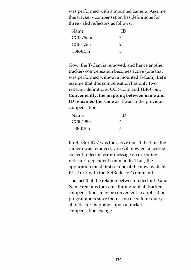
was performed with a mounted camera. Assume this tracker - compensation has definitions for
R-0.5in. ping between name and
D remained the same as it was in the previous
5
the active one at the time the now get a 'wrong
or message on executing Thus, the
now available
eflector ID and
re-query pings upon a tracker
compensation change.
three valid reflectors as follows:
Name ID CCR-75mm 7 CCR-1.5in 2 TBR-0.5in 5
Now, the T-Cam is removed, and hence another tracker- compensation becomes active (one that was performed without a mounted T-Cam). Let's assume that this compensation has only two reflector definitions: CCR-1.5in and TBConveniently, the mapIcompensation:
Name ID CCR-1.5in 2 TBR-0.5in
If reflector ID 7 wascamera was removed, you willcurrent reflector' errreflector- dependent commands. application must first set one of theIDs 2 or 3 with the 'SetReflector' command.
The fact that the relation between rName remains the same throughout all tracker-compensations may be convenient to application programmers since there is no need toall reflector map
170
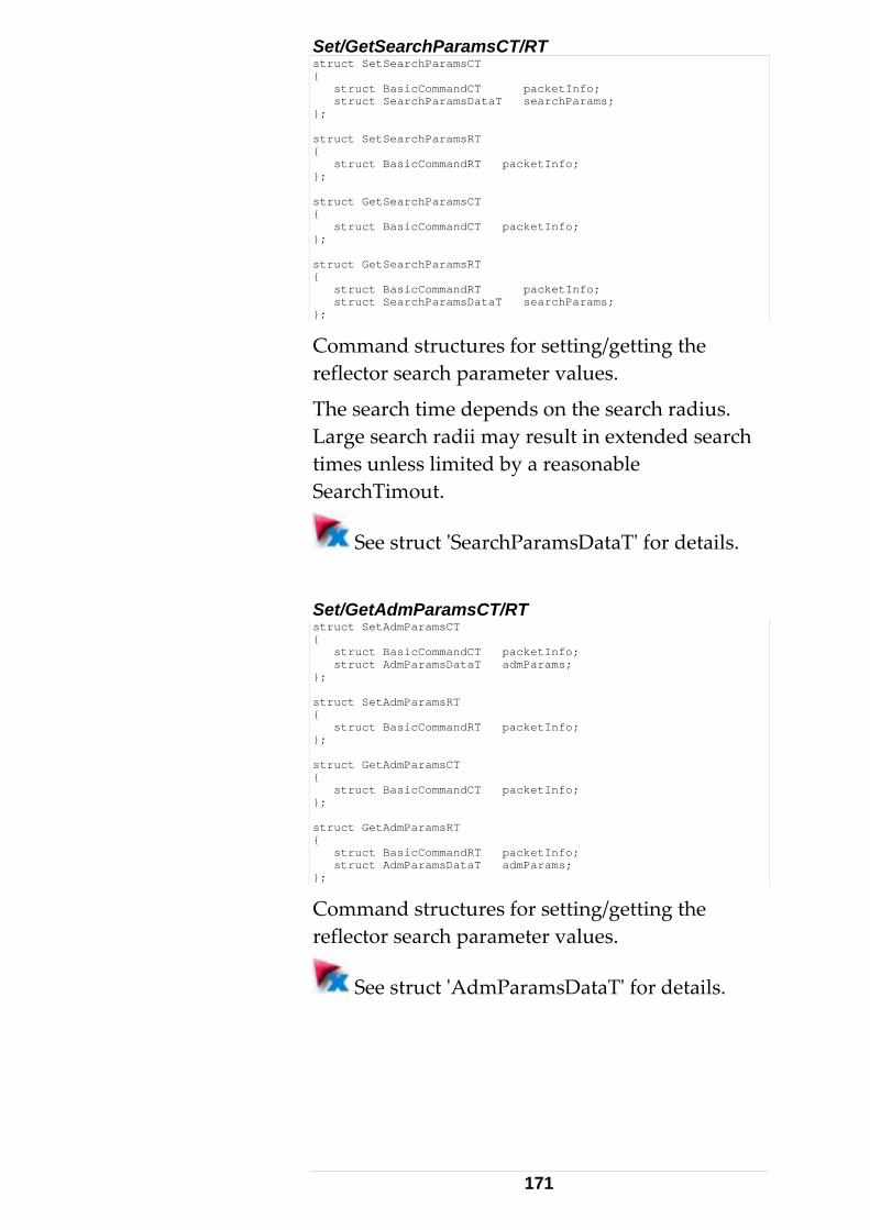
Set/GetSearchParamsCT/RT T struct SetSearchParamsC
{ struct BasicCommandCT packetInfo; struct SearchParamsDataT searchParams; }; struct SetSearchParamsRT { struct BasicCommandRT packetInfo; }; struct GetSearchParamsCT { struct BasicCommandCT packetInfo; }; struct GetSearchParamsRT { struct BasicCommandRT packetInfo; struct SearchParamsDataT searchParams; };
Command structures for setting/getting the reflector search parameter values.
The search time depends on the search radius. arge search radii may result in extended search L
times unless limited by a reasonable SearchTimout.
See struct 'SearchParamsDataT' for details.
/GetAdmParamsCT/RT Setstruct SetAdmParamsCT { struct BasicCommandCT packetInfo; struct AdmParamsDataT admParams; }; struct SetAdmParamsRT { struct BasicCommandRT packetInfo; }; struct GetAdmParamsCT { struct BasicCommandCT packetInfo; }; struct GetAdmParamsRT { struct BasicCommandRT packetInfo; struct AdmParamsDataT admParams; };
Command structures for setting/greflector search parameter values.
etting the
See struct 'AdmParamsDataT' for details.
171

Set/GetEnvironmentParamsCT/RT struct SetEnvironmentParamsCT { struct BasicCommandCT packetInfo; struct EnvironmentDataT environmentData; }; struct SetEnvironmentParamsRT { struct BasicCommandRT packetInfo; }; struct GetEnvironmentParamsCT { struct BasicCommandCT packetInfo; }; struct GetEnvironmentParamsRT { struct BasicCommandRT packetInfo; struct EnvironmentDataT environmentData; };
Command structures for setting/getting the environmental parameter values.
Environmental values are updated automatically at regular intervals, if the weather monitor is on, connected and the WeatherMonitorStatus (of SystemSettings) is one
MS_ReadOnly or S_WMS_ReadAndCalculateRefractions.
of ES_WE
See struct 'EnvironmentDataT' for details.
/GetStationOrientationParamsCT/RT CT
Setstruct SetStationOrientationParams{ struct BasicCommandCT packetInfo; struct StationOrientationDataT stationOrientation; }; struct SetStationOrientationParamsRT { struct BasicCommandRT packetInfo; }; struct GetStationOrientationParamsCT { struct BasicCommandCT packetInfo; }; struct GetStationOrientationParamsRT { struct BasicCommandRT packetInfo; struct StationOrientationDataT stationOrientation; };
Command structures for setting/getting the station orientation parameters. These settings act –input/output 'Filter' to all coordinate-type related
arameters.
like current units and current CS-type – as a
p
172

See struct 'StationOrientationDataT' for
/RT ct SetTransformationParamsCT
details.
Set/GetTransformationParamsCTstru{ struct BasicCommandCT packetInfo; struct TransformationDataT transformationData; }; struct SetTransformationParamsRT { struct BasicCommandRT packetInfo; }; struct GetTransformationParamsCT { struct BasicCommandCT packetInfo; }; struct GetTransformationParamsRT { struct BasicCommandRT packetInfo; struct TransformationDataT transformationData; };
Command structures for setting/getting the settings act –
rrent CS-type – as a ype related
ameters.
transformation parameters. Theselike current units and cuinput/output 'Filter' to all coordinate-tpar
See struct 'TransformationDataT' for details.
/GetBoxRegionParamsCT/RT Setstruct SetBoxRegionParamsCT { struct BasicCommandCT packetInfo; struct BoxRegionDataT boxRegionData; }; struct SetBoxRegionParamsRT { struct BasicCommandRT packetInfo; }; struct GetBoxRegionParamsCT { struct BasicCommandCT packetInfo; }; struct GetBoxRegionParamsRT { struct BasicCommandRT packetInfo; struct BoxRegionDataT boxRegionData; };
Command structures for setting/getting the Box Region parameters.
See struct 'BoxRegionDataT' for details.
173
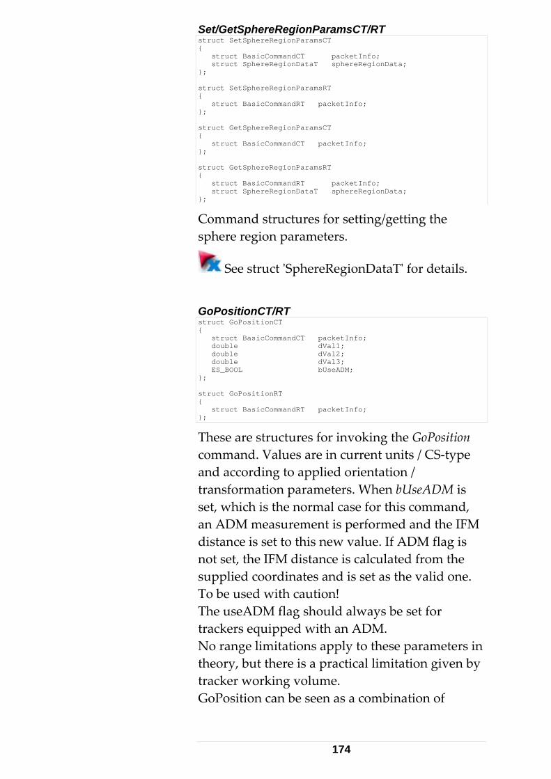
Set/GetSphereRegionParamsCT/RT nParamsCT struct SetSphereRegio
{ struct BasicCommandCT packetInfo; struct SphereRegionDataT sphereRegionData; }; struct SetSphereRegionParamsRT { struct BasicCommandRT packetInfo; }; struct GetSphereRegionParamsCT { struct BasicCommandCT packetInfo; }; struct GetSphereRegionParamsRT { struct BasicCommandRT packetInfo; struct SphereRegionDataT sphereRegionData; };
Command structures for setting/getting the sphere region parameters.
See struct 'SphereRegionDataT' for details.
GoPositionCT/RT struct GoPositionCT { struct BasicCommandCT packetInfo; double dVal1; double dVal2; double dVal3; ES_BOOL bUseADM; }; struct GoPositionRT { struct BasicCommandRT packetInfo; };
These are structures for invoking the Gcommand. Valu
oPosition es are in current units / CS-type
d, d the IFM
g is from the
upplied coordinates and is set as the valid one.
uld always be set for
s in y
combination of
and according to applied orientation / transformation parameters. When bUseADM is set, which is the normal case for this commanan ADM measurement is performed andistance is set to this new value. If ADM flanot set, the IFM distance is calculatedsTo be used with caution! The useADM flag shotrackers equipped with an ADM. No range limitations apply to these parametertheory, but there is a practical limitation given btracker working volume. GoPosition can be seen as a
174
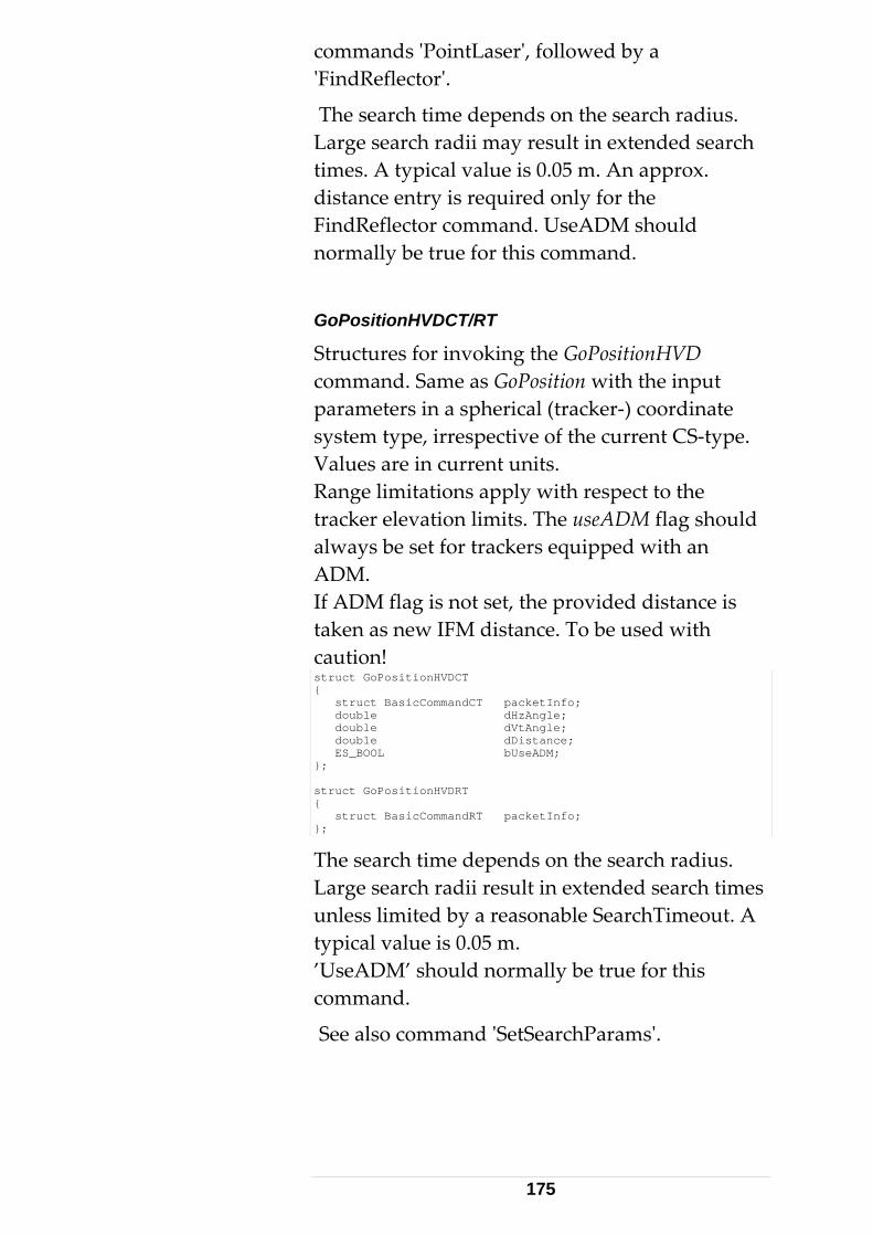
commands 'PointLaser', followed by a 'FindReflector'.
The seaLarge search radii may result in extended searchtimes. A typical value is 0.05 m. An approx. distance e
rch time depends on the search radius.
ntry is required only for the DM should
mand.
T
ositionHVD
ADM flag is not set, the provided distance is ce. To be used with
FindReflector command. UseAnormally be true for this com
GoPositionHVDCT/R
Structures for invoking the GoPcommand. Same as GoPosition with the input parameters in a spherical (tracker-) coordinate system type, irrespective of the current CS-type. Values are in current units. Range limitations apply with respect to the tracker elevation limits. The useADM flag should always be set for trackers equipped with an ADM. Iftaken as new IFM distancaution! struct GoPositionHVDCT { struct BasicCommandCT packetInfo; double dHzAngle; double dVtAngle; double dDistance; ES_BOOL bUseADM; }; struct GoPositionHVDRT { struct BasicCommandRT packetInfo; };
The search time depends on the search radius. xtended search times
less limited by a reasonable SearchTimeout. A .
true for this ommand.
d 'SetSearchParams'.
Large search radii result in euntypical value is 0.05 m’UseADM’ should normally bec
See also comman
175

PositionRelativeHVCT/RT
itionRelativeHV eters are angles in the
he angles are prefixed with +/- ise is -), to specify
direction of movement. In contrast to the
Structures for invoking the Poscommand. The input paramcurrent units. T(clockwise is + and anti clockwtheMoveHV command, PositionRelative means a one-time movement.struct PositionRelativeHVCT { struct BasicCommandCT packetInfo; double dHzVal; double dVtVal; }; struct PositionRelativeHVRT { struct BasicCommandRT packetInfo; };
PointLaserCT/RT
Structures for invoking the PointLaser command. ers are in current units / CS-
orientation / ansformation parameters.
The input paramettype and according to applied trstruct PointLaserCT{ struct BasicCommandCT packetInfo; double dVal1; double dVal2; double dVal3; }; struct PointLaserRT { struct BasicCommandRT packetInfo; };
PointLaserHVDCT/RT
Structures for invoking the PointLaserHVD command. Same as PointLaser with the input parameters in a spherical coordinate system tyirrespective of the selected CS. Values are in current units. struct PointLaser
pe,
HVDCT { struct BasicCommandCT packetInfo; double dHzAngle; double dVtAngle; double dDistance; }; struct PointLaserHVDRT { struct BasicCommandRT packetInfo; };
176
MoveHVCT/RT
Structures for invoking the MoveHV command. tical/horizontal
between 1% and 100% of the .
Use 0 value(s) to stop a previously started mov
quired in- between. contrast to the PositionRelative command,
d rather means 'Start
The input parameters are verspeed valuesmaximum speed of the tracker
ement. MoveHV can be called repeatedly with varying speed values in order to change moving speed. No stop is reInMoveHV does not mean a one-time movement. The MoveHV commanmovement'. struct MoveHVCT { struct BasicCommandCT packetInfo; int iHzSpeed; int iVtSpeed; }; struct MoveHVRT { struct BasicCommandRT packetInfo; };
The speed parameters are prefixed with +/- (clockwise is + and anti clockwise is -), to specifythe direction of movement.
G
oNivelPositionCT/RT struct GoNivelPositionCT { struct BasicCommandCT packetInfo; enum ES_NivelPosition nivelPosition; }; struct GoNivelPositionRT { struct BasicCommandRT packetInfo; };
Structures for invoking the GoNivelPosition command in the orient to gravity procedure. Theinput parameters are the pre-defined Nipositions (1 to 4). This command is mainly ufor the 'O
vel
sed rient to Gravity' command. It is rarely
used by applications unless an own orient to Gravity procedure is implemented.
177
The tracker head moves at a slow speed to i nsor.
kForTargetCT/RT
are in the
ected CS-type / units. The output parameters
his command is mainly used for LT- series of DM). For LTD trackers, rather
m nimize affecting the Nivel se Loo
Structures for invoking the LookForTargetcommand. The input parameters selare always angles related to the tracker coordinate system in the current angle unit settings.
Ttrackers (without Ause 'GoPosition' instead. struct LookForTargetCT { struct BasicCommandCT packetInfo; double dVal1; double dVal2; double dVal3; double dSearchRadius; }; struct LookForTargetRT { struct BasicCommandRT packetInfo; double dHzAngle; double dVtAngle; };
The search time depends on the search radius. ended search
mes. A typical value is 0.05 m.
em in
f bination with LookForTarget).
Large search radii result in extti GetDirectionCT/RT
Structures for invoking the GetDirection command. The output parameters are always angles related to the tracker coordinate systthe current angle unit settings. This command is mainly useful for LT- series otrackers (in comstruct GetDirectionCT { struct BasicCommandCT packetInfo; }; struct GetDirectionRT { struct BasicCommandRT packetInfo; double dHzAngle; double dVtAngle; };
178

Set/GetStatisticModeCT/RT
tinuous 3D measurement tistical
at different data packets for ding on which
de is used.
ption for
ct SetStatisticModeCT
Command structures for setting/getting the statistic mode. Depending on the mode, stationary and/or conpackets will contain more or less stainformation. Note ththe measurement apply depenmo
See enum 'ES_StatisticMode' descridetails. stru{ struct BasicCommandCT packetInfo; enum ES_StatisticMode stationaryMeasurements; enum ES_StatisticMode continuousMeasurements; }; struct SetStatisticModeRT { struct BasicCommandRT packetInfo; }; struct GetStatisticModeCT { struct BasicCommandCT packetInfo; }; struct GetStatisticModeRT { struct BasicCommandRT packetInfo; enum ES_StatisticMode stationaryMeasurements; enum ES_StatisticMode continuousMeasurements; };
Changing the statistical mode is for advanced ode is
ndard' and ensures compatibility to earlier
sCT/RT
ting the .
purposes only. Default statistical m'Staversions.
Set/GetCameraParam
Command structures for setting/getCamera parametersSee also description of struct 'CameraParamsDataT'.
179

struct SetCameraParamsCT { struct BasicCommandCT packetInfo; struct CameraParamsDataT cameraParams; }; struct SetCameraParamsRT { struct BasicCommandRT packetInfo; }; struct GetCameraParamsCT { struct BasicCommandCT packetInfo; }; struct GetCameraParamsRT { struct BasicCommandRT packetInfo; struct CameraParamsDataT cameraParams; };
AddDrivePointCT/RT
Command to add a point to the Drive Point List to be used by the Intermediate Compensation process. See chapter ' Intermediate Compensation ' in main chapter 8 for details. struct AddDrivePointCT { struct BasicCommandCT packetInfo; int iInternalReflectorId; double dVal1; double dVal2; double dVal3; }; struct AddDrivePointRT { struct BasicCommandRT packetInfo; };
CallOrientToGravityCT/RT
Command stGravity’ proc
ructures for executing an ‘Orient To ess (including reception of results).
ataT, to
See special chapter 'Orient to Gravity procedure' ter
Results are in current angle units. Typically, the value dOmega and dPhi are set as dRot1 and dRot2 parameters of StationOrientationDbe passed with the SetStationOrientationParamscommand.
in chap 8.
180
struct CallOrientToGravityCT { struct BasicCommandCT packetInfo; }; struct CallOrientToGravityRT { struct BasicCommandRT packetInfo; double dOmega; double dPhi; };
Error codeA return status other than ES_RS_AllOK (0)
itionultS
command answer status can evaluate to one of the following values:
eceiving data
ase (F) Too many retries due to unstable Nivel
d command
(Some) Nivel results out of valid range o Nivel connected, or Nivel flagged off
ed fatalities.
'Intermediate Compensation' sequence (including
s
means that the command could not be completed. In add to the values defined in ES_Res tatus, the CallOrientToGravity
Code Description 20010 An unknown error occurred (F) 20011 Socket initialization failed (F) 20012 OLE/COM initialization failed (F) 20013 Reading resource string failed (F) 20014 Error on sending data 20015 Error on r20016 No answer within reasonable time 20017 Error on saving results to datab20018
liquid 20019 Invalid count of samples specified(min 2,
max 10) 20020 There was an unexpecte
answer 20021 20022 N20023 /POS270 or /POS90 expected as
command line argument (F) Errors marked with (F) are unanticipat
CallIntermediateCompensationCT/RT
Command structures for executing an
reception of quality result parameters). TotalRMS
181

and maxDev are angular values and are in current ang
Compensation procedure' in chapter 8.
llInt
le units. For details see special chapter 'Intermediate
struct Ca ermediateCompensationCT { struct BasicCommandCT packetInfo; }; struct CallIntermediateCompensationRT { struct BasicCommandRT packetInfo; double dTotalRMS; double dMaxDev; long lWarningFlags; };
Error coden st
In additionES_ResultStatus CallIntermediateCompensation
the followiCode 23011 abase open failure (F)
23013 on database write failure (F) ase
ker getting parameters failed
3 calculated
s A retur atus other than ES_RS_AllOK (0) means that the command could not be completed.
to the values defined in , the
command answer status can evaluate to one of ng values. Description EmScon dat
23012 EmScon database read failure (F) EmSc
23014 No points to measure in datab23020 Tracker initialization failed 23021 Trac23022 Tracker setting parameters failed 23030 There was an unexpected command
answer (F) 23031 Sending data via TCP/IP failed 23032 Error on receiving data (communication
error) 23033 Insufficient memory to create data (F) 23501 At least one of the
mechanical parameters is not in range specified.
182
23502
d/or
23503 angle difference not
Errors m
WarningWarning
etvalue is zintermedwith no warnings. Otherwise, each raised bit
s a ne
CurrentlBit 1 (0x1) ms
y
er than
recommendations.
Too few (less than 2) measurements available. Calculation cannot be performed. Either not enough driving points, or not all could be found anmeasured. Minimum verticalmet An unknown error occurred 23998
arked with (F) are unanticipated fatalities.
flags flags are available upon a successful
compensation (Status ES_RS_AllOK [= 0]). The param er lWarningFlags is a 32-bit value. If the
ero (none of the bits set), then the iate compensation process completed
meanthan o
particular warning. There can be more warning at a time.
y, the following warnings are possible: AverageVerticalTwoFaceErrorIsTooHigh: Tracker service (from Leica Geosystepersonnel) is required because the vertical index is constantly > 1 Gon. There is currently no way for the user to reset the approximate index.
Bit 2 (0x2)
AtLeastOneVerticalTwoFaceErrorIsTooHigh: If Bit 1 not raised, there is probably a verhigh error within a single two-face measurement. If Bit 1 is raised too, ignore warning Bit 2.
Bit 3 (0x4)
AtLeastOneDistanceIsNotInRange: At least one of the distances is smallthe minimum or larger than the maximumrecommended distance, according to the
183

Bit 4 NotEnoughMeas(0x8) anesWithGoodDiffOfVerticalAn
This warning covers all (except the range criterion) possible criteria, which are notfulfilled by the measurement configurationaccording to t
InTwoOppositeVerticalPlgle:
,
he recommendations. edDoubledTwoFaceErrorsAr
olerance: ement residuals are within
s. etersAreInRange:
anical parameters ecommended
rdware specs).
cimal value. Use a is value to a
flagged bits.
C++), a particular bit is wing expression evaluates to TRUE.
Bit 5 NotAllCorrect(0x10) eWithinCompensationT
Not all measurrecommended tolerance
Bit 6 NotAllMechanicalParam(0x20) Not all three (3) mech
calculated are within rtolerance (according to ha
The lWarningFlags value is a descientific calculator to convert thbinary value to visualize the
Programmatically (in C/set if the follo (lWarningFlags & dwCode) // where dwCode is one of the Masks // shown above. For example. 0x10 // tests for 5th bit. See C- reference // for details (bit operations)
CallTransformationCT/RT
Command structures for executing an ‘Transformation’ process (including reception of results). Result values are in current units CS-
r 8 fotype . See chapter 'Transformation Procedure' in chapte r details.
184

struct CallTransformationCT { struct BasicCommandCT packetInfo; }; struct CallTransformationRT { struct BasicCommandRT packetInfo; double dTransVal1; double dTransVal2; double dTransVal3; double dRotVal1; double dRotVal2; double dRotVal3; double dScale; double dTransStdVal1; double dTransStdVal2; double dTransStdVal3; double dRotStdVal1; double dRotStdVal2; double dRotStdVal3; double dScaleStd; double dRMS; double dMaxDev; double dVarianceFactor; };
Error codes A return status other than ES_RS_AllOK (0)
d not be completed.
_ResultStatus, the CallTransformation command he following
Error on reading input data from
e (F) 020 Least Squares Fit failed
r Fit failed Too many unknown nominals
.
for setting/getting the transformation Input parameters. These are used as input for the Transformation calculation process to fix/weight transformation result parameters.
means that the command coulIn addition to the values defined in ESanswer status can evaluate to one of tvalues: Code Description 24010 OLE/COM initialization failed (F)24011 Reading resource string failed (F) 24012
database (F) 24013 Error on saving results to databas2424021 Initial Approximation fo24022 24023 Multiple solutions found Errors marked with (F) are unanticipated fatalities Set/GetTransformationInputParamsCT/RT
Command structures
185

See struct 'TransformationInputDataT' for
ct SetTransformationInputParamsCT details. Also see Section 9.2 . stru{ struct BasicCommandCT packetInfo; struct TransformationInputDataT transformationData; }; struct SetTransformationInputParamsRT { struct BasicCommandRT packetInfo; }; struct GetTransformationInputParamsCT { struct BasicCommandCT packetInfo; }; struct GetTransformationInputParamsRT { struct BasicCommandRT packetInfo; struct TransformationInputDataT transformationData; };
AddTransformationNominalPointCT/RT
Command structures for adding a Point to tNominal point list. See struct 'Transfo
he
rmationPointT ' and also chapter
PointCT
'Transformation Procedure' in chapter 8 for details. struct AddTransformationNominal{ struct BasicCommandCT packetInfo; struct TransformationPointT transformationPoint; }; struct AddTransformationNominalPointRT { struct BasicCommandRT packetInfo; };
AddTransformationActualPointCT/RT
a Point to the formationPointT
rocedure' in pter 8 for details.
ruct AddTransformationActualPointCT
Command structures for addingactual point list. See struct 'Trans' and also chapter 'Transformation Pchast{ struct BasicCommandCT packetInfo; struct TransformationPointT transformationPoint; }; struct AddTransformationActualPointRT { struct BasicCommandRT packetInfo; };
GetTransformedPointsCT/RT
Command structures for retrieving the transformed points and residuals after a successful transformation. Result values are in
186

current units and CS- type (like nominal points). lt packets
specified points through the nominal/actual his approach is similar to the
8 for
esiduals are the difference between the nominal ed actual points.
This command results in as many resuas input points list. TGetReflectors command. See chapter 'Transformation Procedure' in chapterdetails.
Rand the transformstruct GetTransformedPointsCT { struct BasicCommandCT packetInfo; }; struct GetTransformedPointsRT { struct BasicCommandRT packetInfo; int iTotalPoints; double dVal1; double dVal2; double dVal3; double dStdDev1; double dStdDev2; double dStdDev3; double dStdDevTotal; double dCovar12; double dCovar13; double dCovar23; double dResidualVal1; double dResidualVal2; double dResidualVal3; };
GetStillImageCT/RT
Command structures for getting a camera still elivered as a BMP file. Jpeg
esult is a binary ile'
rmat. It can directly be viewed with a bitmap
image. The data is dformat is not supported yet. The rblock (given by start address and size) in 'Ffoviewer. struct GetStillImageCT { struct BasicCommandCT packetInfo; enum ES_StillImageFileType imageFileType; }; struct GetStillImageRT { struct BasicCommandRT packetInfo; enum ES_StillImageFileType imageFiletype; long lFileSize; char cFileStart; };
Only the BMP format is currently supported.
187

GoBirdBath2CT/RT
Command structures for driving the laser to the Bird bath, either in clockwise or counter clockwise direction. struct GoBirdBath2CT { struct BasicCommandCT packetInfo; ES_BOOL bClockWise; }; struct GoBirdBath2RT { struct BasicCommandRT packetInfo; };
GetCompensationCT/RT
Command structures to read the currently active Compensation ID. struct GetCompensationCT { struct BasicCommandCT packetInfo; }; struct GetCompensationRT { struct BasicCommandRT packetInfo; int iInternalCompensationId; };
SetCompensationCT/RT
Command to activate one of the intermediate by tracker compensations delivered
GetCompensations by its ID. struct SetCompensationCT { struct BasicCommandCT packetInfo; int iInternalCompensationId; }; struct SetCompensationRT { struct BasicCommandRT packetInfo; };
GetCompensationsCT/RT
Command structures to read all Tracker reCompensations sto d in the database.
en ID and pensation name is given. As many packets as
(similar to the .
Particularly, the relation betwecomcompensations exist are deliveredGetReflectors command
188

struct GetCompensationsCT { struct BasicCommandCT packetInfo; }; struct GetCompensationsRT { struct BasicCommandRT packetInfo; int iTotalCompensations; int iInternalCompensationId; unsigned short cTrackerCompensationName[32]; unsigned short cTrackerCompensationComment[128] unsigned short cADMCompensationName[32]; ES_BOOL bHasMeasurementCameraMounted; };
GetCompensations2CT/RT
Enhanced version of GetCompensationsCT/RT rmation. has been left only for
r er applications u ations2CT/RT.
G tC
with some additional infoGetCompensationsCT/RTbackwa d compatibility. Newshould se GetCompens
ct e ompensations2CT stru{ struct BasicCommandCT packetInfo; }; struct GetCompensations2RT { struct BasicCommandRT packetInfo; int iTotalCompensations; int iInternalCompensationId; unsigned short cTrackerCompensationName[32]; unsigned short cTrackerCompensationComment[128] unsigned short cADMCompensationName[32]; unsigned short cADMCompensationComment[128]; ES_BOOL bHasMeasurementCameraMounted; ES_BOOL bIsActive; };
CheckBirdBathCT/RT
Command structures to check the Bird bath osition of the current, selected reflector. Values
s. pare in current unitstruct CheckBirdBathCT { struct BasicCommandCT packetInfo; }; struct CheckBirdBathRT { struct BasicCommandRT packetInfo; double dInitialHzAngle; double dInitialVtAngle; double dInitialDistance; double dHzAngleDiff; double dVtAngleDiff; double dDistanceDiff; };
GetTrackerDiagnosticsCT/RT
ommand structures to read tracker diagnostic data. This is a command mainly used for service purposes.
C
189

struct GetTrackerDiagnosticsCT { struct BasicCommandCT packetInfo; }; struct GetTrackerDiagnosticsRT { struct BasicCommandRT packetInfo; double dTrkPhotoSensorXVal; double dTrkPhotoSensorYVal; double dTrkPhotoSensorIVal; double dRefPhotoSensorXVal; double dRefPhotoSensorYVal; double dRefPhotoSensorIVal; double dADConverterRange; double dServoControlPointX; double dServoControlPointY; double dLaserLightRatio; int iLaserControlMode; double dSensorInsideTemperature; int iLCPRunTime; int iLaserTubeRunTime; };
GetADMInfoCT/RT
Command structures to read ADM-specific cker must be equipped diagnostic data. The tra
wit an ADM. struct GetADMInfoCT { struct BasicCommandCT packetInfo; }; struct GetADMInfoRT { struct BasicCommandRT packetInfo; int iFirmWareMajorVersionNumber; int iFirmWareMinorVersionNumber; int iSerialNumber; };
GetNivelInfoCT/RT
Command structures to read NIVEL20-specific diagnostic data. The tracker must have a NIVEL20 sensor connected and enabled. struct GetNivelInfoCT { struct BasicCommandCT packetInfo; }; struct GetNivelInfoRT { struct BasicCommandRT packetInfo; int iFirmWareMajorVersionNumber; int iFirmWareMinorVersionNumber; int iSerialNumber; };
GetTPInfoCT/RT
Command structures to read TP-specific diagnostic data. This is a command mainly usefor service purposes.
d
190
struct GetTPInfoCT { struct BasicCommandCT packetInfo; }; struct GetTPInfoRT { struct BasicCommandRT packetInfo; int iTPBootMajorVersionNumber; int iTPBootMinorVersionNumber; int iTPFirmWareMajorVersionNumber; int iTPFirmWareMinorVersionNumber; int iLCPFirmWareMajorVersionNumber; int iLCPFirmWareMinorVersionNumber; enum ES_TrackerProcessorType trackerprocessorType; enum ES_TPMicroProcessorType microProcessorType; int iMicroProcessorClockSpeed; enum ES_LTSensorType laserTrackerSensorType; };
SetLaserOnTimerCT/RT
Command structure to set the time in hours and minutes (rounded off to nearest ¼ hour block) to
itched-off by a oller
ze, this am laser-on in the
e laser can be independently switched off. ruct SetLaserOnTimerCT
start the laser previously swSwitchLaser(off) command. The tracker contrand emScon server must be switched on. Since the laser takes about 20 minutes to stabilicommand is useful to progrmorning so the system is ready when work isscheduled to begin.
Thst{ struct BasicCommandCT packetInfo; int iLaserOnTimeOffsetHour; int iLaserOnTimeOffsetMinute; }; struct SetLaserOnTimerRT { struct BasicCommandRT packetInfo; };
GetLaserOnTimerCT/RT
to read the time left in nearest ¼
he laser. A system restart er processor /
Scon server must be switched on.
Command structureshours and minutes (rounded off tohour block), to start tsets this value to zero. The trackemstruct GetLaserOnTimerCT { struct BasicCommandCT packetInfo; }; struct GetLaserOnTimerRT { struct BasicCommandRT packetInfo; int iLaserOnTimeOffsetHour; int iLaserOnTimeOffsetMinute; };
191

ConvertDisplayCoordinatesCT/RT
tion. is a private
ction/command and is not upported. It should not be used for
ct ConvertDisplayCoordinatesCT
Command structures to call the DisplayCoordinateConversion funcDisplayCoordinateConversion fundocumented/sany client programming stru{ struct BasicCommandCT packetInfo; enum ES_DisplayCoordinateConversionType conversionType; double dVal1; double dVal2; double dVal3; }; struct ConvertDisplayCoordinatesRT { struct BasicCommandRT packetInfo; double dVal1; double dVal2; double dVal3; };
Set/GetTriggerSourceCT/RT
Command structures to Set/Get Trigger SouSee enum 'ES_TriggerSource' for details. Note: Trigger functionality is not yet available with emScon 2.1.x releases and may be schange! struct SetTriggerSourceCT
rce.
ubject to
{ struct BasicCommandCT packetInfo; enum ES_TriggerSource triggerSource; }; struct SetTriggerSourceRT { struct BasicCommandRT packetInfo; }; struct GetTriggerSourceCT { struct BasicCommandCT packetInfo; }; struct GetTriggerSourceRT { struct BasicCommandRT packetInfo; enum ES_TriggerSource triggerSource; };
GetFaceCT/RT Cw
ommand structures to query current Tracker Face, hether in Face I or Face II position.
192
struct GetFaceCT { struct BasicCommandCT packetInfo; }; struct GetFaceRT { struct BasicCommandRT packetInfo; enum ES_TrackerFace trackerFace; };
GetCamerasCT/RT
Cp
ommand structure to get Measurement Camera roperties. The GetCameras command retrieves
fined. The s
ver database. These n camera name (string)
et, in ontains the total
l number of kets to be expected (only for programmer's
rties, such as mment, etc. serve
s information, mainly used for user-interface
all measurement cameras (T-Cams) deanswer consists of as many answer packets acameras are defined in the serresolve the relation betweeand camera ID (numerical). Each packaddition (a redundancy), cnumber of cameras, i.e. the totapacconvenience). Other propecameraType, serial Number, coapurpose. struct GetCamerasCT { struct BasicCommandCT packetInfo; }; struct GetCamerasRT { struct BasicCommandRT packetInfo; int iTotalCameras; int iInternalCameraId; long lSerialNumber; enum ES_MeasurementCameraType cameraType; unsigned short cName[32]; unsigned short cComment[128]; };
GetCameraCT/RT
Command structure to get the ID of the acCamera. The GetCamera command deliverscurrently active measurement camera by its ID(Currently set as the active one in the databHowever, since this camera may have been removed, an additional flag indicates wh
tive the
ase).
ether the active camera is mounted or not.
193

struct GetCameraCT { struct BasicCommandCT packetInfo; }; struct GetCameraRT { struct BasicCommandRT packetInfo; int iInternalCameraId; ES_BOOL bMeasurementCameraIsMounted; };
Set/GetMeasurementCameraModeCT/RT
tures for setting/getting the Command strucmeasurement camera mode. struct SetMeasurementCameraModeCT { struct BasicCommandCT packetInfo; enum ES_MeasurementCameraMode cameraMode; }; struct SetMeasurementCameraModeRT { struct BasicCommandRT packetInfo; }; struct GetMeasurementCameraModeCT { struct BasicCommandCT packetInfo; }; struct GetMeasurementCameraModeRT { struct BasicCommandRT packetInfo; enum ES_MeasurementCameraMode cameraMode; };
GetProbesCT/RT
Command structure to get Probe properties. GetProbes command retrieves all probes definedin the Tracker Server. The answer consists of as many answer packets as probes are defined in theserver database. These resolve the relation between probe name (string) and probe ID (numerical). Each packet, in addition (a redundancy), contains the total number of probes, i.e. the total number of packets to be expected (only for programmer's convenience).Other properties, such as probeType, serial Number, comment, etc. serve as informationmainly used for user
, -interface purpose.
194

struct GetProbesCT { struct BasicCommandCT packetInfo; }; struct GetProbesRT { struct BasicCommandRT packetInfo; int iTotalProbes; int iInternalProbeId; long lSerialNumber; enum ES_ProbeType probeType; int iNumberOfFields; unsigned short cName[32]; unsigned short cComment[128]; };
GetProbeCT/RT
Command structure to get the ID of active Probe. and delivers the currently
The GetProbe commactive probe by its ID (Currently set as the activeone in the database). struct GetProbeCT { struct BasicCommandCT packetInfo; }; struct GetProbeRT { struct BasicCommandRT packetInfo; int iInternalProbeId; };
GetTipAdaptersCT/RT
re to get measurement Tip nd
rieves all tip adapters defined for the Tracker erver. The answer consists of as many answer
erver
(numerical). ns
.
Command structuproperties. The GetTipAdapters commaretSpackets as tips adapters are defined in the sdatabase. These resolve the relation between tipname (string) and tip adapter IDEach packet, in addition (a redundancy), contaithe total number of tip adapters, i.e. the total number of packets to be expected (only for programmer's convenience). Other properties, such as tipType, serial Number, comment, etcserve as information, mainly used for user-interface purpose.
195

struct GetTipAdaptersCT { struct BasicCommandCT packetInfo; }; struct GetTipAdaptersRT { struct BasicCommandRT packetInfo; int iTotalTips; int iInternalTipAdapterId; long lAssemblyId; long lSerialNumberLowPart; long lSerialNumberHighPart; enum ES_TipType tipType; double dRadius; double dLength; unsigned short cName[32]; unsigned short cComment[128]; };
GetTipAdapterCT/RT
get the ICommand structures to apter. The GetTipAdapter co
D of active Tip mmand delivers
e currently active tip adapter by its ID base).
Adth(Currently set as the active one in the dataIn addition to the ID, the adapter number, to which the tip is attached, is returned. struct GetTipAdapterCT { struct BasicCommandCT packetInfo; }; struct GetTipAdapterRT { struct BasicCommandRT packetInfo; int iInternalTipAdapterId; int iTipAdapterInterface; };
Get/SetTCamToTrackerCompensationsCT/RT
am To Tracker ions command
racker Server. The answer consists of as many ned in the server
.
Command structures to get T-CCompensation properties. TheGetTCamToTrackerCompensatretrieves all such compensations defined in the Tanswer packets as tips are defidatabase. These resolve the relation between compensation name (string) and compensation ID (numerical). Each packet, in addition (a redundancy), contains the total number of compensations, i.e. the total number of packets to be expected (only for programmer's convenience)Other properties, such as tracker Serial Number, comment, etc. serve as information, mainly used
196
for user-interface purpose. There is a flag bIsActive which is true for exactly one compensation. struct GetTCamToTrackerCompensationsCT { struct BasicCommandCT packetInfo; }; struct GetTCamToTrackerCompensationsRT { struct BasicCommandRT packetInfo; int iTotalCompensations; int iInternalTCamToTrackerCompensationId; int iInternalTrackerCompensationId; int iInternalCameraId; ES_BOOL bIsActive; long lTrackerSerialNumber; unsigned short cTCamToTrackerCompensationName[32]; unsigned short cTCamToTrackerCompensationComment[128]; };
T/Get/SetTCamToTrackerCompensationC RT
of the
t/SetTCamToTrackerCompensation command ID as parameter.
Command structures to get/set the ID active T-Cam to tracker compensation. The Getakes/delivers the compensationstruct SetTCamToTrackerCompensationCT { struct BasicCommandCT packetInfo; int iInternalTCamToTrackerCompensationId; }; struct SetTCamToTrackerCompensationRT { struct BasicCommandRT packetInfo; }; struct GetTCamToTrackerCompensationCT { struct BasicCommandCT packetInfo; }; struct GetTCamToTrackerCompensationRT { struct BasicCommandRT packetInfo; int iInternalTCamToTrackerCompensationId; };
GetProbeCompensationsCT/RT
Command structure to get Probe Compensation
mand retrieves all such compensations nswer
defined in the server database. These resolve the relation between compensation name (string) and compensation ID (numerical). Each packet, in
properties. The GetProbeCompensations comdefined in the Tracker Server. The aconsists of as many answer packets as probes are
197

anumber of compensations, i.e. the total number of pconvenience). Other properties, such as tracker Sinpurpose. There is a flag bIsActive which is true fo st
ddition (a redundancy), contains the total
ackets to be expected (only for programmer's
erial Number, comment, etc. serve as formation, mainly used for user-interface
r exactly one compensation.
ruct GetProbeCompensationsCT { struct BasicCommandCT packetInfo; }; struct GetProbeCompensationsRT { struct BasicCommandRT packetInfo; int iTotalCompensations; int iInternalProbeCompensationId; int iInternalProbeId; int iFieldNumber; ES_BOOL bIsActive; ES_BOOL bMarkedForExport; ES_BOOL bPreliminary; unsigned short cProbeCompensationName[32]; unsigned short cProbeCompensationComment[128]; };
Get/SetProbeCompensationCT/RT
active
command kes/delivers the compensation ID as only
C ommand structures to get/set the ID ofProbe compensation. The Get/SetProbeCompensationtaparameter.
struct SetProbeCompensationCT { struct BasicCommandCT packetInfo; int iInternalProbeCompensationId; }; struct SetProbeCompensationRT { struct BasicCommandRT packetInfo; }; struct GetProbeCompensationCT { struct BasicCommandCT packetInfo; }; struct GetProbeCompensationRT { struct BasicCommandRT packetInfo; int iInternalProbeCompensationId; };
GetTipToProbeCompensationsCT/RT
Command structures to get Tip to probe Compensation properties. The GetTipToProbeCompensations command
198
retrieves all such compensations defined in the ny
d in the server
name (string) and compensation ket, in addition (a
tal number of of packets
to be expected (only for programmer's
nderlying probe compensations, comment, etc. inly used for user-
CT
Tracker Server. The answer consists of as maanswer packets as tips are definedatabase. These resolve the relation between compensationID (numerical). Each pacredundancy), contains the tocompensations, i.e. the total number
convenience). Other properties, such as userve as information, mainterface purpose.
struct GetTipToProbeCompensations{ struct BasicCommandCT packetInfo; }; struct GetTipToProbeCompensationsRT { struct BasicCommandRT packetInfo; int iTotalCompensations; int iInternalTipToProbeCompensationId; int iInternalTipAdapterId; int iTipAdapterInterface; int iInternalProbeCompensationId; ES_BOOL bMarkedForExport; unsigned short cTipToProbeCompensationName[32]; unsigned short cTipToProbeCompensationComment[128]; };
G
Command structures to get the ID of active Tip to Probe- compensation. There is no related 'Set' cGetTipToProbeCompensation command delivers the compensation ID as only parameter.
struct GetTipToProbeCompensationCT
etTipToProbeCompensationCT/RT
ommand since detection is automatic. The
{ struct BasicCommandCT packetInfo; }; struct GetTipToProbeCompensationRT { struct BasicCommandRT packetInfo; int iInternalTipToProbeCompensationId; };
199
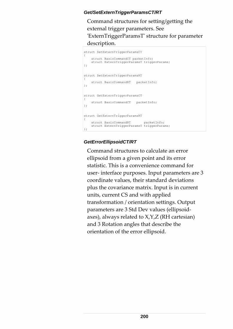
Get/SetExternTriggerParamsCT/RT
g/getting the ee ture for parameter
Command structures for settinexternal trigger parameters. S'ExternTriggerParamsT' strucdescription.
struct SetExternTriggerParamsCT { struct BasicCommandCT packetInfo; struct ExternTriggerParamsT triggerParams; }; struct SetExternTriggerParamsRT { struct BasicCommandRT packetInfo; }; struct GetExternTriggerParamsCT { struct BasicCommandCT packetInfo; }; struct GetExternTriggerParamsRT { struct BasicCommandRT packetInfo; struct ExternTriggerParamsT triggerParams; };
ate an error lipsoid from a given point and its error
ence command for
n current
tesian) e
GetErrorEllipsoidCT/RT
Command structures to calculelstatistic. This is a conveniuser- interface purposes. Input parameters are 3 coordinate values, their standard deviations plus the covariance matrix. Input is iunits, current CS and with applied transformation / orientation settings. Output parameters are 3 Std Dev values (ellipsoid- axes), always related to X,Y,Z (RH carand 3 Rotation angles that describe thorientation of the error ellipsoid.
200

struct GetErrorEllipsoidCT { struct BasicCommandCT packetInfo; double dCoord1; double dCoord2; double dCoord3; double dStdDev1; double dStdDev2; double dStdDev3; double dCovar12; double dCovar13; double dCovar23; }; struct GetErrorEllipsoidRT { struct BasicCommandRT packetInfo; double dStdDevX; double dStdDevY; double dStdDevZ; double dRotationAngleX; double dRotationAngleY; double dRotationAngleZ; };
GetMeasurementCameraInfoCT/RT
Command structures to read T-CAM-specifiinformation and diagnostic data of the activecamera. The tracker must be equipped wMeasurement camera.
c
ith a
struct GetMeasurementCameraInfoCT { struct BasicCommandCT packetInfo; }; struct GetMeasurementCameraInfoRT { struct BasicCommandRT packetInfo; int iFirmWareMajorVersionNumber; int iFirmWareMinorVersionNumber; long lSerialNumber; ES_MeasurementCameraType cameraType; unsigned short cName[32]; long lCompensationIdNumber; long lZoomSerialNumber; long lZoomAdjustmentIdNumber; long lZoom2DCompensationIdNumber; long lZoomProjCenterCompIdNumber; double dMaxDistance; double dMinDistance; long lNrOfPixelsX; long lNrOfPixelsY; double dPixelSizeX; double dPixelSizeY; long lMaxDataRate; };
GetMeasurementProbeInfoCT/RT
Command structures to read Probe-specific information and diagnostic data of the active probe.
201
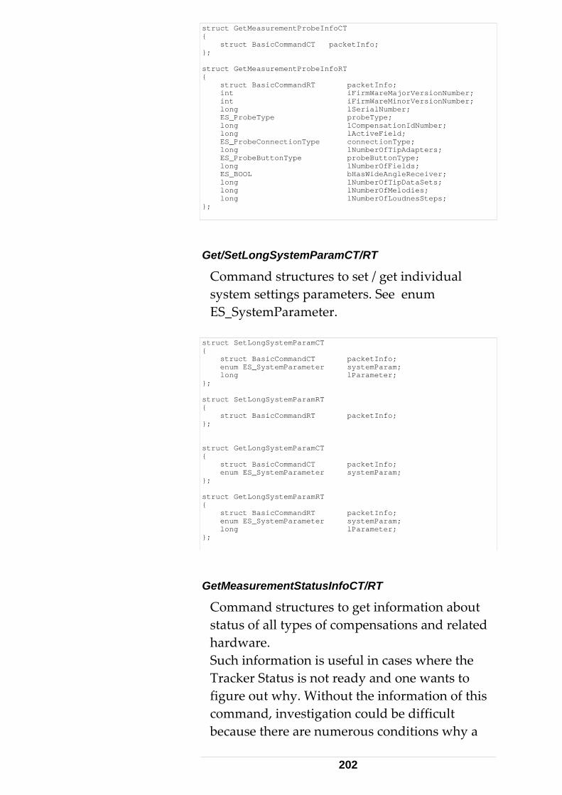
struct GetMeasurementProbeInfoCT { struct BasicCommandCT packetInfo; }; struct GetMeasurementProbeInfoRT { struct BasicCommandRT packetInfo; int iFirmWareMajorVersionNumber; int iFirmWareMinorVersionNumber; long lSerialNumber; ES_ProbeType probeType; long lCompensationIdNumber; long lActiveField; ES_ProbeConnectionType connectionType; long lNumberOfTipAdapters; ES_ProbeButtonType probeButtonType; long lNumberOfFields; ES_BOOL bHasWideAngleReceiver; long lNumberOfTipDataSets; long lNumberOfMelodies; long lNumberOfLoudnesSteps; };
G
ettings parameters. See enum S_SystemParameter.
et/SetLongSystemParamCT/RT
Command structures to set / get individual system sE
struct SetLongSystemParamCT { struct BasicCommandCT packetInfo; enum ES_SystemParameter systemParam; long lParameter; }; struct SetLongSystemParamRT { struct BasicCommandRT packetInfo; }; struct GetLongSystemParamCT { struct BasicCommandCT packetInfo; enum ES_SystemParameter systemParam; }; struct GetLongSystemParamRT { struct BasicCommandRT packetInfo; enum ES_SystemParameter systemParam; long lParameter; };
GetMeasurementStatusInfoCT/R
Command structures to get informationstatus of all types of compensations anhardware.
T
about d related
Such information is useful in cases where the Tracker Status is not ready and one wants to figure out why. Without the information of this command, investigation could be difficult because there are numerous conditions why a
202
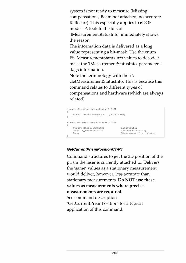
system is not ready to measure (Missing hed, no accurate
applies to 6DOF
’ immediately shows e reason.
The information data is delivered as a long value representing a bit-mask. Use the enum ES_MeasurementStatusInfo values to decode / mask the 'lMeasurementStatusInfo' parameters flags information. Note the terminology with the 's': GetMeasurementStatusInfo. This is because this command relates to different types of compensations and hardware (which are always related)
struct GetMeasurementStatusInfoCT
compensations, Beam not attacReflector). This especiallymodes. A look to the bits of ‘lMeasurementStatusInfoth
{ struct BasicCommandCT packetInfo; }; struct GetMeasurementStatusInfoRT { struct BasicCommandRT packetInfo; enum ES_ResultStatus lastResultStatus; long lMeasurementStatusInfo; };
GetCurrentPrismPositionCT/RT
Command structures to get the 3D position of the prism the laser is currently attached to. Delivers the ‘same’ values as a stationary measurement would deliver, however, less accurate than stationary measurements. Do NOT use these values as measurements where precise measurements are required. See command description ‘GetCurrentPrismPosition’ for a typical application of this command.
203

struct GetCurrentPrismPositionCT { struct BasicCommandCT packetInfo; }; struct GetCurrentPrismPositionRT { struct BasicCommandRT packetInfo; double dVal1; double dVal2; double dVal3; };
204

3.5 C - Language TPI Programming Instructions
ta
ver the
evel
fined.
compiler
nection
e)
Number to 700 for
toolbox
and
e
The C-TPI is made- up of a pure collection of enumeration types and data structures. The datastructures reflect the 'architecture' of the dapackets (= byte arrays) sent and received oTCP/IP network, between the Application Processor and the Tracker Server. This (low- l) interface serves as the basis for all higher level interfaces (C++, COM)
Also refer to C- Language TPI Reference sectionand the ES_C_API_Def.h file.
No functions or procedures are de
Since C++ is an extension of C, a C++can also be used for C programming.
3.5.1 TCP/IP Con1. Establish a TCP/IP connection to the tracker server. This is typically achieved by invoking a Connect function of the TCP/IP communication library or toolbox. This function will take the IP address (or its related hostnamof your Tracker Server.
2. Set the TCP/IP Portthe Tracker Server. 3.5.2 Sending Commands 3. Call a SendData function from the TCP/IP communication library or(Function name may differ). This function typically takes a pointer to a data packetprobably the size of it (unless the packet is wrapped into a structure that knows its sizimplicitly, for example a Variant structure).
205

4. The architecture of the packets (TPI rotocol) is defined by the data structures in the
oPositionCT and
pES_C_API_Def.h file.
5. For invoking for example a GoPosition command, use the structure Gassign appropriate initialization values. In particular, assign an ES_Command and an ES_C_GoPosition as header- data and provide 3 coordinate values as command parameters. The compiler will not detect, if, for example, an ES_DT_SingleMeasResult as type, or an ES_C_SwitchLaser as command is assigned to a GoPositionCT variable. Inappropriate initializationvalues cause the command to fail.
GoPosition initialization sample: GoPositionCT data; // declare packet variable data.packetInfo.packetHeader.type = ES_DT_Command; data.packetInfo.packetHeader.lPacketSize = sizeof(data); data.packetInfo.command = ES_C_GoPosition; data.dVal1 = -1.879; data.dVal2 = 2.011; data.dVal3 = 0.551; data.bUseADM = FALSE;
Note: emScon Version 1.5 was tolerant ininitializing ‘packetHeader.lPacketSize’ upon sending commands. This is no longer the case for emScon V2.0 and up. Correct Initialization of ‘lPacketSize’ is compulsory! 3.5.3 Initialization Macros 6. To avoid initialization errors, which may happen through copy/paste errors and adifficult to trace, it is recommended to use initialization macros for correct assignment of type, size and command values. An INITStopMeasurement macr
not
re
o , for example,
the parameter initialization acro call). The StopMeasurement has no
additional command parameters. If there are any, these can be incorporated into the macro.
requires two statements, the parameterdeclaration and(m
206

StopMeasurementCT cmdStop; // declaration INITStopMeasurement(cmdStop); // initialization
3.5.4 Excurse: C++ Initialization C++ offers a much more elegant way finitialization – the 'constructor' approach, whicheases the initialization issues.
See a C++ programmers referen
or
ce for details.
e data variable, the TCP/IP
function is on
d . Alternatively, a
Sendata packet variable, Send (&data, sizeof(data)). 3.5.5 om Tracker Server 8. for threqueimmeaction, the tracker server sends an answer back to the client. Depending on the command, it may
g the
7. After initialization of thsend it to the tracker server usingSendData() function (or whatever thiscalled). Depending on the TCP/IP communicatilibrary used, the data packet may need to be packed into a Variant vrtData variable, followeby a SendData (vrtData) call
d() function takes the address and size of the
Answers frThe SendData() function does not wait
e Tracker Server (tracker) to complete the sted action - SendData() will return diately. On completion of the requested
take a few seconds between sendincommand and receiving an answer. This requires some type of notification or callback mechanism. That is, as soon as data arrives from the Tracker Server, some sort of event needs to trigger aReadData() procedure in the client application. Depending on the TCP/IP communication, this notification could be a Windows Message, an Event or a Callback Function.
This type of communication is called asynchronous.
207

3.5.6 Asynchronous Communication 9. From the programmer's point of viewasynchronous communication is much more difficult to handle than synchronous communication. The p
,
rogrammer must ensure, of
ious one has returned.
() is called
. epending on the toolkit:
return a Variant data.
in a
data e,
y.
ueued,
ts may be queued
en parsing the byteArr uffer.
not to send a new command until the answer the prev 3.5.7 DataArrived Notification 10. All TCP/IP communication libraries/toolkits contain either a DataArrivednotification or a similar function, whichby the framework each time data has arrivedD
• The function may directlytype parameter that contains the
• The function may deliver the data witharray. byte
• The function returns the size of thepacket that is ready to be read. In this casthe DataArrived() function subsequently calls a ReadData() function immediately, in order to get the data into a local byte arra
3.5.8 Data arrival 'Traffic Jams' 11. If a 'traffic jam' occurs on the incoming TCP/IP line, i.e., if incoming data is being qa ReadData() call will read all the currently available data with no notification for each individual packet. Many packeand only one DataArrived notification might be issued. This means that the byteArr buffer will contain more than one packet. This may occur on high frequency, continuous measurement streams. The application has to make provisions to correctly treat such cases. The lPacketSize value is most convenient whb
208
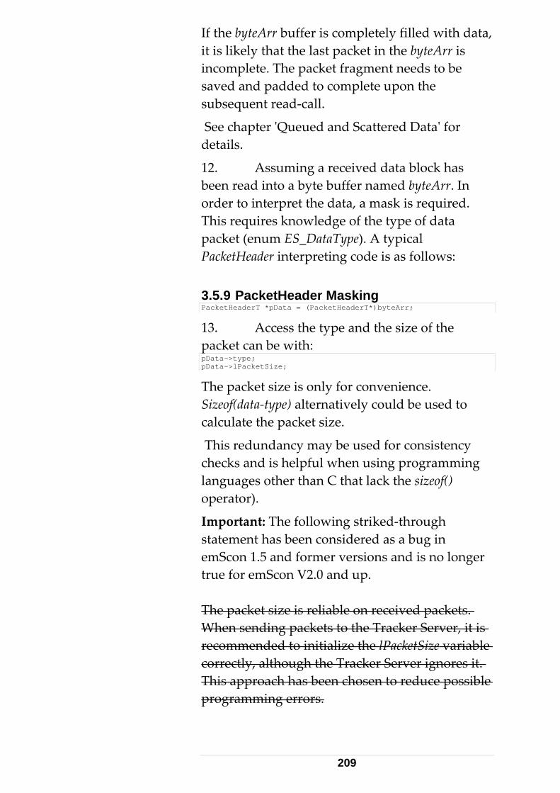
If the byteArr buffer is completely filled with dait is likely that the last packet in the byteArr isincomplete. The packet fragment needs to be saved and padded to complete upon the subsequent read-call.
S
ta,
ee chapter 'Queued and Scattered Data' for
s
details.
12. Assuming a received data block habeen read into a byte buffer named byteArr. In order to interpret the data, a mask is required. This requires knowledge of the type of datapacket (enum ES_DataType). A typical PacketHeader interpreting code is as follows: 3.5.9 PacketHeader Masking PacketHeaderT *pData = (PacketHeaderT*)byteArr;
13. Access the type and the size of the packet can be with: pData->type; pData->lPacketSize;
The packet size is only for convenience. Sizeof(data-type) alternatively could be used to calculate the packet size.
This redundancy may be used for consistency checks and is helpful when using programming languages other than C that lack the sizeof() operator).
Important: The following striked-through statement has been considered as a bug in emScon 1.5 and former versions and is no longer true for emScon V2.0 and up. The packet size is reliable on received packets. When sending packets to the Tracker Server, it is recommended to initialize the lPacketSize variable correctly, although the Tracker Server ignores it. This approach has been chosen to reduce possible programming errors.
209

From emScon Version 2.0 and up: lPacketSize
s was ersions.
pe Switch swers require a
nt to distinguish the command all
riate s
ommand, of the handling of a single
e wer:
must be initialized correctly also on sending packets. This information is essential and no longer ignored by the tracker server as thithe case for previous emScon server v 3.5.10 Command Subty14. Command type answitch statemesubtype. Non-data returning commands canbe treated the same and are handled in the default switch statement. All other command a wers need to be masked with the approns pre ult structure. The code fragment below demonstrates this with the GetUnits cand shows part m asurement ans
210

switch (pData->type) { case ES_DT_Command: // 'command- type' answer arrived { BasicCommandRT *pData2 = (BasicCommandRT *)byteArr; // if something went wrong, no need to continue if (pData2->status != ES_RS_AllOK) { // TODO: evaluate and handle the error return false; } switch (pData2->command) { case ES_C_Initialize: case ES_C_PointLaser: case ES_C_FindReflector: break; case ES_C_GetUnits: { GetUnitsRT *pData3 = (GetUnitsRT *)byteArr; // Diagnostics - check whether packet size // as expected (in debug mode only) ASSERT(pData3->packetInfo. packetHeader.lPacketSize == sizeof(GetUnitsRT)); // now you can access Unit specific data. pData3->unitsSettings.lenUnitType; pData3->unitsSettings.tempUnitType; break; } // case XXX: // Todo: add other command type evaluations // break; default: break; } } break; case ES_DT_SingleMeasResult: // single-meas-result- { //type answer has arrived SingleMeasResultT *pData4 = (SingleMeasResultT *)byteArr; if (pData4->packetInfo.status != ES_RS_AllOK) return false; break; } // Todo: add further 'case' statements // for remaining packet types }
• Declaring variables within case statements,which are suitable for masking data, requicurly brackets around a particular case block. Otherwise the compiler will cla
re
im.
he top of a switch statement, for example multi-measurement results (not covered above).
• If-then-else can be used instead of switch statements. However, switches are more efficient.
• Frequent items should be treated at t
211

3.6 C Language TPI - Samples
Some older Samples distributed with former emScon versions have been dropped because
no longer exist for the emScon V2.0 till provided
at's the reason
owever, even if the names have not changed, earlier
versions. Sample 4 (see C++ section) has been com
3.6.1 Impleapplicoverhead or MFC or ATL. This sample fits into a singlecomments and empty lines), and compiles into a sm l
This and G nce no Windows Me aa mulrequires events and threads. For TCP/IP communication, the Winsock API functions are used.Further details see 'Readme.txt' file in Sample 3 folder and code- comments in source files. Console
The VC++ AppWizard or a text editor can be used to create a 'Console Application' skeleton, and to implem
they have 'expired'. For Example Samples 1 and Sample 2 doSDK. Nevertheless, the samples shave not been re-named. ThSample 3 is the first one referenced here. Hthe samples might have improved since
pletely revised for example)
Sample 3 ments a 'lightweight' C-TPI client ation, with no graphical interface, GUI
file with 350 lines of code (including
al executable file.
sample implements only Initialize Tracker et Direction commands. Si
ss ge Loop is available, the application needs ti threaded approach and therefore
Application
ent the C standard entry function:
212
int main(int argc, char* argv[]) { }
Add allextension) and invoke the C compiler from the command line.
CommTheseEmsyCApiConsoleClient.cpp.
nclude <stdio.h> // standard C input/output
the source code, save the file (.c or .cpp
ents comments refer to the file
The following include- files are required: #i#include <Winsock2.h> // win32 socket stuff
•connection by calling the function TcpIpConnect(), starts the Data Receivthread and enters an endless 'User Interfaloop'. The default I
The main() function first does a TCP/IP
er ce
P address “192.168.0.1”
passed as command- line argument
r input of one of the s 'i' for Initialize Tracker
e
ect().
After connecting, call
has been created
al variable. This variable must be initialized with the return value of a WSACreateEvent() call.
should be adjusted to the actual server address. Alternatively, the IP address can beupon running the application.
• This loop looks for usetwo TPI commandand 'g' for Get Direction.
• If the user enters x, the loop is stopped, thTCP/IP connection is closed and the application terminates. The TcpIpConnect() function is straightforward up to the call of conn
• Call WSAStartup. WSAEventSelect(), which takes the following parameters:
- A socket handle (thatbefore) as a global variable.
- An event of type WSAEVENT as a glob
213

- A flags parameter. FD_READ is passed,
n would have
ework to signal the passed event, whenever data has arrived at the socket.
WaitForSingleObject(g_hSocketEvent, INFINITE);
indicating an interest in data-arrival events (a realistic applicatioto also trap FD_CLOSE events).
Calling this function will cause the TCP/IP fram
The DataRecvThread() has an infinite loop with thefollowing statement:
This is a blocking call and causes the loop to stountil the event is signaled to be read. The blocking by the WaitForSingleObject is released and the loop passes on.
p,
on
sions to handle such situations with a
nsmission rate by
creasing buffer sizes.
ee Win32 documentation for more information about Winsock API (especially the WSA… function), threads and events.
See also 'Sample 9' (Receiving Data) in the C++ TPI section. Notice the comments in the source code.
Reset the event before available data is read into abuffer.
Call a function ProcessData() that does the interpretation of the buffer.
Queuing (Traffic Jams) There are no provisions to handle 'traffic jams'the network. A real application needs to make provipacket size transmitted in the header of each packet. The Winsock function setsockopt() may beused to 'tune' TCP/IP train
S
214

Remarks This sample can easily be ported to non-Win32 platforms (Unix, Linux, and Mac).
Creating a 'console' application requires the use
elect() be more appropriate. It issues
insock API.
than the Winsock OCX control.
syncSocket and CSocket classes in
of the WSAEventSelect() function with events and threads. Excurse: Windows Application
This chapter points out the options we had if we chosen a Windows application instead of a Console application.
For Windows applications, the WSAAsyncSfunction would Window messages instead of events and is simpler to handle. No separate thread is required (the window message loop takes this part).
See Win32 documentation on WSAAsyncSelect().
Winsock API In Windows applications, the Winsock OCX control could be used instead of the WHowever, the Winsock API functions are moreefficient The use of a MFC library permits even a veryconvenient class wrapper around the Winsock API.
Refer to the CAC++ section for details.
215

4 C++ Interface
4.1 Class- based TPI Programming 4.1.1 Preconditions
iented programming. ass-
ous rogramming concepts and TCP/IP socket
.
he description of the classes in this chapter may
iscrepancies, the information in the regarded as
t provide any additional
lasses
h data structure (of the C-
CESAPIReceive supports receiving and parsing
Using the C++ interface requires sufficient knowledge of object- orA programmer should at least know about cldesign, class- inheritance, virtual functions, member function overloads, asynchronpprogramming
This chapter describes wrapper-classes for data structures and two main classes used for sending commands and receiving answers.
Tbe slightly discrepant to the contents of the ES_CPP_API_Def.h file in the SDK. In case of dES_CPP_API_Def.h file should becorrect.
Sample 4 (former Sample 4_2 in emScon 1.5) comprises all these topics. This sample is most suitable for introduction into emScon C++ programming.
The C++ TPI does nofunctions for the Tracker Server. It is built upon the C TPI and is made up of one include file, ES_CPP_API_Def.h with ES_C_API_Def.h as its basis. The C++ interface implements two cCESAPICommand and CESAPIReceive, apart from wrapper classes for eacTPI).
CESAPICommand handles sending of commands from the client application to the TS and
216

data sent by the Tracker Server to the client application.
The advantage of a class design is the avof construct
ailability ors to perform (struct) initialization.
every platform.
This chapter does not touch TCP/IP basic issues.
A Tracker Server C++ interface is preferable to a C low-level interface, if a C++ compiler is available.
4.1.2 Platform Issues Tracker Server client programming remains platform independent since C++ compilers are available for virtually
4.1.3 TCP/IP
See C- TPI section since this topic is independentfrom the TPI- type used (except COM interface)
4.2 C++ Language TPI Reference 4.2.1 CESAPICommand class
ndPacket Se virtual bool SendPacket(void* PacketStart, long PacketSize);
Thi irtual function must be implementedass derived from CESAPICommand. Its
cket library.
s v in the climplementation depends on the selected TCP/IP so
Om
Example for a command taking no parameters ( Initialize the tracker): bool Initialize();
Command Functions
nly a few sample of the class' command ember functions are listed here since these can
be derived directly from the C- interface.
Example for a command taking basic- type parameters:
217

bool SetContinuousTimeModeParams(long lTimeSeparation, long lNumberOfPoints, bool bUseRegion, ES_RegionType regionType);
Example for a command taking a struct parameter: bool SetContinuousTimeModeParams(ContinuousTimeModeDataT continuousTimeModeData);
The latter two functions are different ovthe same function.
Many of the command- function exist in two different overloads. Depending on context, it be more suitable for an application to use onthe other overload.
A complete
erloads of
may e or
listing of all these functions is ommand class
ames
ied to a
the prefix 'ES_C_' from the ill be the name of
the C++ function. [
ters, add the
TPI
available from the CESAPICdefinition in the file 'ES_CPP_API_Def.h' file.
Rather than redundantly listing all of these member functions in this chapter, a general ruleis presented on how to derive the function nfrom the related C-TPI structures. (The text in [brackets] shows the rule applsample).
1. Look up the command of interest in the 'enum ES_Command' (C- TPI Reference). [ES_C_SetContinuousTimeModeParams]
2.) Removecommand tag- name. This w
SetContinuousTimeModeParams ()]
3.) For finding the input paramePostfix 'CT' to the remaining command- tag name. [SetContinuousTimeModeParamsCT].
4.) Look up this CT structure in the C-reference for a description of all the parameters.
218

4.2.2 CESAPIReceive class ReceiveData bool ReceiveData(void* packetStart, long packetSize);
ReceiveData is the parser- function for incoming
ta from the emScon server. data. It has to be called after receiving a block of da
COMPLETE (in terms of an RT struct as defined in the C-API). Packet fragments are not processed co
packets. See chapter 'Queued and Scattered Data' fo
The principle is as follows: Derive your own class from CESAPIReceive and override those virtual
nctions on whose data you are interested in.
al data
Example for a command returning no data. If this function is called this means the command has successfully executed ( i.e the tracker has finished initial virtual void OnInitializeAnswer()
Packets passed to this method must be
rrectly. Hence the application (which calls ReceiveData) must ensure to pass complete
r details. Data Arrival virtual Functions
fu
Only a few sample of the class' virtureceiver member functions are listed here sincethese can be derived directly from the C- interface.
izing):
Example for a command returning data. (Which is the virtual void OnGetContinuousTimeModeParamsAnswer(
case for all 'Get...' functions). const ContinuousTimeModeDataT& continuousTimeModeData)
A complete listing of all these functions is availadefinition in the file 'ES_CPP_API_Def.h' file.
Rather than redundantly listing all of these member functions in this chapter, a general rule is presented on how to derive the function names fro
ble from the CESAPIReceive class
m the related C-TPI structures.
219
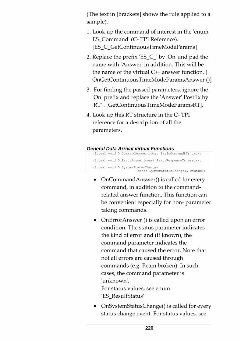
(The text in [brackets] shows the rule applied to a sample).
1. L oES_[ES
2. Replace the prefix 'ES_C_' by 'On' and pad the name with 'Answer' in addition. This will be the name of the virtual C++ answer function. [ OnGetContinuousTimeModeParamsAnswer ()]
3. Fo'On'RT' . [GetContinuousTimeModeParamsRT].
4. L orefepar
Gener virtual void OnCommandAnswer(const BasicCommandRT& cmd);
o k up the command of interest in the 'enum Command' (C- TPI Reference). _C_GetContinuousTimeModeParams]
r finding the passed parameters, ignore the ' prefix and replace the 'Answer' Postfix by
o k up this RT structure in the C- TPI rence for a description of all the ameters.
al Data Arrival virtual Functions virtual void OnErrorAnswer(const ErrorResponseT& error); virtual void OnSystemStatusChange( const SystemStatusChangeT& status);
• OnCommandAnswer() is calledcommand, in addition to the com
for every mand-
unction. This function can specially for non- parameter
rror atus parameter indicates
at
ch cases, the command parameter is
every status change event. For status values, see
related answer fbe convenient etaking commands.
• OnErrorAnswer () is called upon an econdition. The stthe kind of error and (if known), the command parameter indicates the command that caused the error. Note thnot all errors are caused through commands (e.g. Beam broken). In su
'unknown'. For status values, see enum 'ES_ResultStatus'
• OnSystemStatusChange() is called for
220

enum 'ES_SystemStatusChange'
• Note that virtual functions are only called if defined int the derived receiver class. Particular arrival data can be ignoredappropriate virtual function defin
if the ition is
omitted.
e signature of the y .
atching signatures will result in not- calling the functions. The compiler cannot
• Attention: Make sure thvirtual function in the derived class exactlmatches the signature in ' CESAPIReceive 'However, the keyword 'virtual' is optional in the derived class.
• Mism
detect such kind of errors.
• It is therefore recommended to copy/paste the virtual function header from CESAPIReceive to the derived class.
4.3 C++ Language TPI Programming Instruc
tions
tual
sending uired, as they are
and instead.
ReceiveData, which is called on data arrival
4.3.1 Sending Data The class CESAPICommand contains a virfunction SendPacket(), which must be overwritten. This approach allows convenient 'Send…' command functions.
Dealing with C data structures forcommands is no longer reqcompletely 'hidden'. Use the related member functions of CESAPIComm 4.3.2 Receiving Data In order to select the data the application is interested in, CESAPIReceive offers a method
221
events, as well as numerous virtual membefunctions..
Dealing with C d
r
ata structures for receiving data no longer required, as they are completely
, apart from structure (of the C-
tage of on issues. The
n,
class is used to send to the tracker server, the class
SAPIReceive is used to receive data.
ass
SCON_NAMESPACE
is'hidden'. Use the related (virtual) memberfunctions of CESAPIReceive instead.
4.3.3 Class Design Issues All class member functions are defined 'inline'. Neither a library nor a .cpp file is required. One single include file suffices. The C++ interface is fully transparent with complete source code provided.
The C++ interface implements two classes named CESAPICommand and CESAPIReceivewrapper classes for each dataTPI). A class design has the advanconstructors to delegate initializaticlass CESAPICommand has a virtual functioSendPacket(), which must be overwritten using Send… command functions.
While the CESAPICommanddata CE
The principle is as follows: Derive your own clfrom CESAPIReceive class and override those virtual functions on whose data you are interested in. Details see below in 'CESAPIReceive' chapter.
Insertion of the statement #define ES_USE_EM
before the inclusion of the ES_CPP_API_Def.h file, PP
name conflicts with other (third-party) libraries.
defines a namespace EmScon for the TPI Cclasses. This is only required in case of potential
222
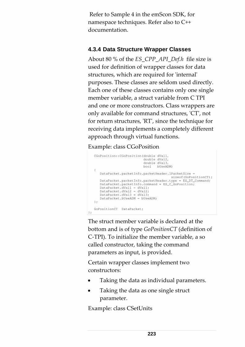
Refer to Sample 4 in the emScon SDK, for
Data Structure Wrapper Classes e is
gle
are and structures, 'CT', not
return structures, 'RT', since the technique for eceiving data implements a completely different
unctions.
namespace techniques. Refer also to C++ documentation.
4.3.4About 80 % of the ES_CPP_API_Def.h file sizused for definition of wrapper classes for datastructures, which are required for 'internal' purposes. These classes are seldom used directly.Each one of these classes contains only one sinmember variable, a struct variable from C TPI and one or more constructors. Class wrappersonly available for commforrapproach through virtual f
Example: class CGoPosition CGoPosition::CGoPosition(double dVal1, double dVal2, double dVal3, bool bUseADM) { DataPacket.packetInfo.packetHeader.lPacketSize = sizeof(GoPositionCT); DataPacket.packetInfo.packetHeader.type = ES_DT_Command; DataPacket.packetInfo.command = ES_C_GoPosition; DataPacket.dVal1 = dVal1; DataPacket.dVal2 = dVal2; DataPacket.dVal3 = dVal3; DataPacket.bUseADM = bUseADM; }; GoPositionCT DataPacket; };
The struct member variable is declared at thebottom and is of type GoPositionCT (definition oC-TPI). To initialize the member variable, a so called constructor, taking the command parameters as input, is provided.
Certain wrapper classes implement two constructors:
• Taking the data as individual param
• Taking the data as one single struct parameter.
f
eters.
xample: class CSetUnits E
223
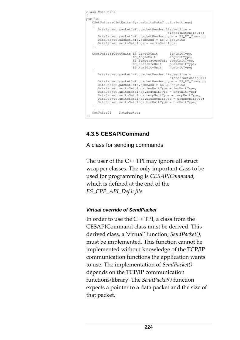
class CSetUnits { public: CSetUnits::CSetUnits(SystemUnitsDataT unitsSettings) { DataPacket.packetInfo.packetHeader.lPacketSize = sizeof(SetUnitsCT); DataPacket.packetInfo.packetHeader.type = ES_DT_Command; DataPacket.packetInfo.command = ES_C_SetUnits; DataPacket.unitsSettings = unitsSettings; }; CSetUnits::CSetUnits(ES_LengthUnit lenUnitType, ES_AngleUnit angUnitType, ES_TemperatureUnit tempUnitType, ES_PressureUnit pressUnitType, ES_HumidityUnit humUnitType) { DataPacket.packetInfo.packetHeader.lPacketSize = sizeof(SetUnitsCT); DataPacket.packetInfo.packetHeader.type = ES_DT_Command; DataPacket.packetInfo.command = ES_C_SetUnits; DataPacket.unitsSettings.lenUnitType = lenUnitType; DataPacket.unitsSettings.angUnitType = angUnitType; DataPacket.unitsSettings.tempUnitType = tempUnitType; DataPacket.unitsSettings.pressUnitType = pressUnitType; DataPacket.unitsSettings.humUnitType = humUnitType; }; SetUnitsCT DataPacket; };
4.3.5 CESAPICommand
e C++ TPI may ignore all struct rapper classes. The only important class to be
ing is CESAPICommand,
de of SendPacket
S d class must be derived. This
SendPacket(), us n cannot be pl he TCP/IP
ts )
nd the size of
A class for sending commands The user of thwused for programmwhich is defined at the end of the ES_CPP_API_Def.h file.
Virtual overri
In order to use the C++ TPI, a class from theCE APICommanderived class, a 'virtual' function, m t be implemented. This functioim emented without knowledge of tcommunication functions the application wanto use. The implementation of SendPacket(depends on the TCP/IP communicationfunctions/library. The SendPacket() function expects a pointer to a data packet athat packet.
224
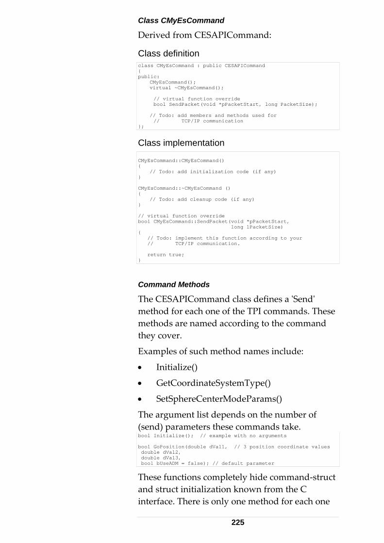
Class CMyEsCommand
Derived from CESAPICommand:
Class definition class CMyEsCommand : public CESAPICommand { public: CMyEsCommand(); virtual ~CMyEsCommand(); // virtual function override bool SendPacket(void *pPacketStart, long PacketSize); // Todo: add members and methods used for // TCP/IP communication };
Class implementation CMyEsCommand::CMyEsCommand() { // Todo: add initialization code (if any) } CMyEsCommand::~CMyEsCommand () { // Todo: add cleanup code (if any) } // virtual function override bool CMyEsCommand::SendPacket(void *pPacketStart, long lPacketSize) { // Todo: implement this function according to your // TCP/IP communication. return true; }
Command Methods
The CESAPICommand class defines a 'Send' method for each one of the TPI commands. These methods are named according to ththey cover.
Examples of such method nam
• Initialize()
• GetCoordinateS
• SetSphereCenterModeParams()
The argument list depends on the number of(send) parameters these commands take. bool Initialize(); // example with no arguments
e command
es include:
ystemType()
bool GoPosition(double dVal1, // 3 position coordinate values double dVal2, double dVal3, bool bUseADM = false); // default parameter
These functions completely hide command-struct and struct initialization known from the C interface. There is only one method for each one
225
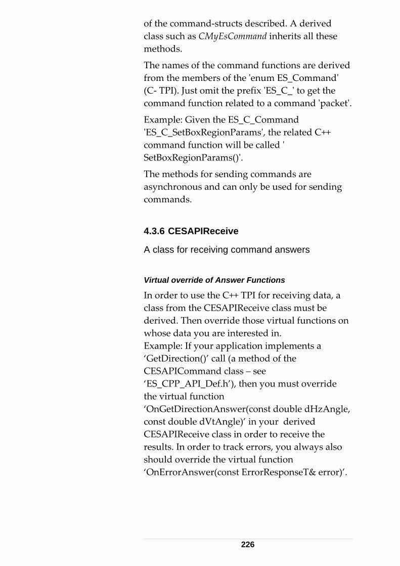
of the command-structs described. A derived ll these
d e members of the 'enum ES_Command'
- TPI). Just omit the prefix 'ES_C_' to get the o a command 'packet'.
nd ams', the related C++
'
e methods for sending commands are synchronous and can only be used for sending
lass from the CESAPIReceive class must be functions on
ror)’.
class such as CMyEsCommand inherits amethods.
The names of the command functions are derivefrom th(Ccommand function related t
Example: Given the ES_C_Comma'ES_C_SetBoxRegionParommand function will be calledc
SetBoxRegionParams()'.
Thacommands.
4.3.6 CESAPIReceive
A class for receiving command answers Virtual override of Answer Functions
In order to use the C++ TPI for receiving data, a cderived. Then override those virtualwhose data you are interested in. Example: If your application implements a ‘GetDirection()’ call (a method of the CESAPICommand class – see ‘ES_CPP_API_Def.h’), then you must override the virtual function ‘OnGetDirectionAnswer(const double dHzAngle, const double dVtAngle)’ in your derived CESAPIReceive class in order to receive the results. In order to track errors, you always also should override the virtual function ‘OnErrorAnswer(const ErrorResponseT& er
226

Class CMyESAPIReceive
Code Sample: (only class and function
es for complete
declaration is shown here, not the implementation. Refer to samplcode).
lass CMyESAPIReceive:c
public CESAPIReceive { // override virtual functions of those // answers you are interested in: protected: void OnErrorAnswer(const ErrorResponseT&); void OnGetSearchParamsAnswer(const SearchParamsDataT& searchParams); };
Secomplete example on how to implement the two cl'CFurther see the (revised) Sample 4 (= Sample 4.2 inCESAPICommand class (ESCppClient_Step3) and
4. ued and Scattered Data WthabA
p to the configured buffer size), single data re
ct to tion by a Read call (depending on
your communication tools, this can be recv, GetData, CAsyncSocket::Receive() etc.).
These read functions are not able to recognize packet boundaries. Read functions read all data that is currently available (In practice, the data
e Sample 9 (EmsyCPPApiConsoleClient) for a
asses derived from 'CESAPICommand' and ESAPIReceive’.
emScon 1.5) on how to deal with the
the CESAPIReceive class (ESCppClient_Step4).
3.7 Quehen the Tracker Server delivers more data rough the TCP/IP network than the client is le to process, it results in 'traffic jams'.
lthough, the TCP/IP network buffers such data (upackets will be queued. That is, there are no mo'gaps' between the data packets. When the client is notified from the TCP/IP communication framework that data has arrived, it has to reathis notifica
227

will be read in one read- cycle, limited to a certainffer size).
or only
hes:
ead-buffer and read all on
sing the size of each packet.
ket, the next read- rom the
are obably the most
, since it minimizes the number
plex one in terms of data parsing.
e the size of cket Size)
ethod: 'Peek' (instead of Read) the ithout removing data from the socket.
, read as many bytes as ample below.
s (if data blocks n
0 API
bu
These might be several combined packetsa fraction of a (trailing) packet.
Problem Solution There are several possible approac
1. Provide a sufficient rthat is currently pending. The client applicatiparses the data block into packets, uheader information andWith a fragmented last paccycle is started and the two fragments fprevious and the current reading assembled together. This is prefficient methodof reading interrupts. However, it is also the most com
2. Read only the header to determinthe first pending packet. The rest of the pais estimated by reading (packetSize – headerbytes. Variant mheader, wWith known sizeindicated by packetSize. See code s
The sample code shown below demonstrates a method to ensure complete packetarrive scattered) and to avoid data congestio(traffic jams). It is based on Winsock 2.functions:
228

LRESULT CMsgSink::OnMessageReceived(UINT uMsg, WPARAM wParam, LPARAM lParam, BOOL& bHandled) { // The read-buffer is kept static for performance reasons. // In a real application better make it a member // variable of CMsgSink // static char szRecvBuf[RECV_BUFFER_SIZE]; bool bOK = true; long lReady = 0; int nCounter = 0; long lMissing = 0; long lBytesRead = 0; long lPacketSize = 0; long lBytesReadTotal = 0; int nHeaderSize = sizeof(PacketHeaderT); PacketHeaderT *pHeader = NULL; TRACE(_T("CMsgSink::OnMessageReceived(%lu, %lu)\n"), wParam, lParam); if (WSAGETSELECTEVENT(lParam) == FD_READ) { // Just peek the header, do not remove data from queue lReady = recv((SOCKET)wParam, szRecvBuf, nHeaderSize, MSG_PEEK); if (lReady < nHeaderSize) { if (lReady == SOCKET_ERROR) { if (WSAGetLastError() == WSAEWOULDBLOCK) Sleep(50); // busy - try later else { Beep(1000, 100); // not able to get header } // else } // if return true; // non-fatal only a peek, try next time! } // if pHeader = (PacketHeaderT*)szRecvBuf; bOK = bOK && lReady == nHeaderSize && pHeader->lPacketSize >= nHeaderSize && pHeader->lPacketSize < RECV_BUFFER_SIZE && pHeader->type >= ES_DT_Command && pHeader->type <= ES_DT_ReflectorPosResult; lPacketSize = pHeader->lPacketSize; if (bOK) { do { nCounter++; if (lBytesRead > 0) lBytesReadTotal += lBytesRead; lMissing = lPacketSize - lBytesReadTotal; lBytesRead = recv((SOCKET)wParam, (szRecvBuf + lBytesReadTotal), lMissing, 0); if (lBytesRead == SOCKET_ERROR) { if (WSAGetLastError() == WSAEWOULDBLOCK) { Sleep(50); // busy - try later continue; } else Beep(1000, 100); } // if if (nCounter > 64) // emergency exit { if (lBytesReadTotal <= 0) { TRACE(_T("not able to read data (recv)\n")); return true; // nothing read, can leave safely } // if
229
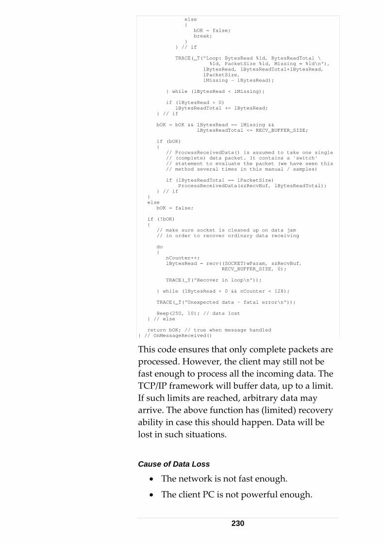
else { bOK = false; break; } } // if TRACE(_T("Loop: BytesRead %ld, BytesReadTotal \ %ld, PacketSize %ld, Missing = %ld\n"), lBytesRead, lBytesReadTotal+lBytesRead, lPacketSize, lMissing - lBytesRead); } while (lBytesRead < lMissing); if (lBytesRead > 0) lBytesReadTotal += lBytesRead; } // if bOK = bOK && lBytesRead == lMissing && lBytesReadTotal <= RECV_BUFFER_SIZE; if (bOK) { // ProcessReceivedData() is assumed to take one single // (complete) data packet. It contains a 'switch' // statement to evaluate the packet (we have seen this // method several times in this manual / samples) if (lBytesReadTotal == lPacketSize) ProcessReceivedData(szRecvBuf, lBytesReadTotal); } // if } else bOK = false; if (!bOK) { // make sure socket is cleaned up on data jam // in order to recover ordinary data receiving do { nCounter++; lBytesRead = recv((SOCKET)wParam, szRecvBuf, RECV_BUFFER_SIZE, 0); TRACE(_T("Recover in loop\n")); } while (lBytesRead > 0 && nCounter < 128); TRACE(_T("Unexpected data - fatal error\n")); Beep(250, 10); // data lost } // else return bOK; // true when message handled } // OnMessageReceived()
This code ensures that only complete packets are processed. However, the client may still not be fast enough to process all the incoming data. The TCP/IP framework will buffer data, up to a limit.
ery ata will be
ause of Data Loss
• The network is not fast enough.
• The client PC is not powerful enough.
If such limits are reached, arbitrary data may arrive. The above function has (limited) recovability in case this should happen. Dlost in such situations.
C
230

• The application is not able to process data
signed
fast enough.
• The application is not deappropriately.
The client application can still buffer
ts as list elements). This approach can be chosen if the
aused by I
etwork with
incoming data, for example, in a FIFO list (taking the data packe
performance constraint is cintensive data processing. The Winsock APoffers certain 'tuning' functions. These allow, for example, to alter internal nbuffers. Increasing the receive- buffersetsockopt(), for example, may increase data throughput significantly.
#define SOCKET_READ_BUFFER_SIZE (256 * 1024) // 256 KB buffer int nBufSize = SOCKET_READ_BUFFER_SIZE; int nVarSize = sizeof(nBufSize); // it's 4 byte, but sizeof is better style! nRet = setsockopt(m_sock, SOL_SOCKET, SO_RCVBUF, (char *)&nBufSize, nVarSize); ASSERT(nRet != SOCKET_ERROR);
See documentation on setsockopt() for further details.
4.3.8 Partial Settings Changes Consider the command 'SetUnits'. This command takes all selectable unit- types (Length, Angular, Temperature, Pressure, Humidity) as parameterHowever, often one wants to change only one othese and leave the others untouched.
The best mefi
s. f
thod to do so is invoking a 'GetUnits' rst, then change only the one parameter of
etUnits'.
same M interface).
interest and finally do a 'S
Here is a C++ sample (although the approach also applies to C and CO
231

GetUnits(); // trigger a 'GetUnitsCommand' // The current units are delivered in such that // the following virtual function will be called: void OnGetUnitsAnswer(unitsSettings) { SystemUnitsDataT newUnits = unitsSettings; // change angle unit and leave rest untouched newUnits.angUnitType = ES_AU_Degree; // restore changed parameters // (assumed g_cmdObj is a pointer to your ApiCommand obj) g_cmdObj->SetUnits(newUnits); }
Note: since the parameter of the OnGetUnitsAnswer() is designed as 'const', it is necessary to use a local struct 'newUnits'. It is not
ired
y mand has more
truct parameter).
e
'queue' commands ider
. ith a
te s are
possible to directly change 'unitsSettings'.
Another 'favorite' for this technique is the command 'SetSystemSettings'. Often it is requto change only one of the different flags of the 'SetSystemSettings' parameters.
However, this technique can be used for everSet/Get command pair (if the comthan one parameter or a s
4.3.9 Asynchronous Programming Issues As already stated, all communication through thC++ interface is asynchronous.
It is therefore not possible towithin one function call. In other words, consa Windows application with a graphical interfaceAssume a button named 'InitialSettings' wbutton- press handler as follows behind (Nothis is pseudo code since no parameterspecified): OnInitialSettingsButtonPressed() { m_myApiCmd->SetUnits(...); m_myApiCmd->SetEnvironmentParams(...); m_myApiCmd->Initialize(); m_myApiCmd->GetReflectors(); m_myApiCmd->SetMeasurementMode(...); }
This won't work at all because this a typical a
cosynchronous approach (i.e. It is assumed
mmand has finished when it returns). In an
232

asynchronous approach, each command returns immediately. In the sample above, SetUnits() and SetEnvironmentParams() may accidentally work (because these commands do not take a long time – thterminate – also returns immediately. The server, however, is not ready to take the next command un
'S
NsyseHinterface, some answers remain asynchronous by nachange events and 'multi- packet' command an'G
Thnever issues a command before the previous one hacommand always indicates its termination by sending an 'acknowledgment'. With the C++
'O(pnocohaCE
Inissprevious command has arrived. There are several possible approaches to achieve correct execution of
1.
but never rely on this!). But Initialize() – since is command takes about 45 seconds to
til initialization of tracker is finished. Hence the command ' GetReflectors()' would fail with a
erver busy' error.
ote: The emScon COM interface provides a nchronous interface which allows to queue veral commands in one and the same function. owever, even when using the synchronous
ture. These are error events, system status
swers, such as 'GetReflectors', etCompensations' etc.
e correct approach is that the application
s returned. Even a non- parameter returning
interface, either the general nCommandAnswer()' can be used for that ractically only suitable for commands that do t return any results). In addition, every mmand has its individual 'On..Answer()' ndler. See 'ES_CPP_API_Def.h' file, SAPIReceive class.
particular, the next command may not be ued before the 'On..Answer()' handler of the
a series of commands :
Directly call the next command in the 'On..Answer()' of the previous command. This
233

approach is demonstrated with the 'GetReflectors' / 'GetReflector()' sequence in Step4 of Sample 4. Remark: There is a helper function InitReflectorBox() in OnGetReflectorsAnswerThe next command ' GetReflector()' is called ithis 'InitReflectorBox()' function. Howev'GetReflector()' could also be called inside 'OnGetReflectorsAnswer()' function d
Queue your commands in a list. Take the fircommand from the list and send it to the tracker server. At the same time, set an Event(or another synchronization object, suchMutex or Semaphore)' that prevents taking tnext command from the list. As soon as the answer of the pending command arrives, rethe Event, which will cause to process the next command from the list. In contrast to the fiO
(). n
er,
irectly.
2. st
as
he
set
rst approach, where each n..Answer() handler calls a different
is
ess
. Queue your commands in a list. Use an dler nd
of the list and sends it to the tracker server. To and- chain', do an explicit first
call
dvantage of this approach is that no
f
subsequent command, this second approachmore general in such that every answer handler does the same: 'ResetEvent'. Needlto say that this approach means a multi threaded application.
3application-defined Windows message hanthat removes and processes the first comma
start the 'commcall of this message handler. In every 'On..Answer()' handler, a 'PostMessage()' will cause to trigger the message handler in order to process the next command. (Importantto use PostMessage, not SendMessage). The amulti- threaded application is required since the Windows message loop takes care osynchronization. On the other hand, this
234

approach only works for windowsand not for console applications or 'windowless serve
applications
r applications' (Hint: you may use an
is
plication
ton handler calls only one command. The user himself must make sure he does not press a button while a
ing command has not terminated. The that it
con COM nous
s COM ).
TPI Samples
invisible window for message handling).
4. To be complete, the most simple approach also mentioned here, although this does not really mean an 'automated queuing' of commands: Let the synchronization to the user! This means that the apimplements an individual Button for everycommand, i.e. every but
pendapplication can support the user in such disables all buttons while a command is in action. (Disable all buttons when pressing any button, enable all again when a 'On..Answer()' handler is called.
The 'asynchronous issues' of this chapter also apply to the C- Interface and the emSinterface – as far as using the asynchrointerface (or those parts of the synchronouinterface that remain asynchronous by nature
4.4 C++ Language 4.4.1 Sample 4
dialog user- interface and makes use of
d required dialog
This sample is designed as a 4 Step by Step tutorial. It is a Windows application with a graphicalthe MFC framework. Step1:
Step 1 offers a simple dialog- based MFC application. It has added some dialog controls with message handlers an
235

member variables already defined. However, all message handlers are empty (exceptBeep).
The framework has been created using the AppWizard and ClassWizard and then a bit cleaned up manually in order to keep the code as slim as possible (Eliminated icon
s, rc2 and pre-ompiled headers). In a real application, these
ould be left of course.
f
to
mechanism to achieve this.
cthings c
Note that the Step 1 application does not yet depend on emScon at all.
Step2:
Step 2 adds TCP/IP communication to the application. There are several ways to do this:
- use an appropriate Socket Class (that's what we do in this application - we use CAsyncSocket oMFC)
- use the Winsock2 C-library (as for example usedin the 'Sample9' of the emScon SDK)
- use the Winsck.ocx ActiveX control.
- use any other third-party socket library
We need to provide the following functions:
- connect to server
- disconnect from server
- write data to previously opened server connection
In addition, we need a notification mechanism get informed that data has arrived and is ready tobe read.
Since this is a Windows application, we can use the window message
(Note that in a non- windows application, we would need to use events and threads to achievethe same - see Sample9).
236
So far nothing depends from the emScon SDK - we do not need any emScon- include file yet. Allis provided by the VC++ developme
nt Kit. But
evertheless we will be able to connect to /
allow to send real emScon commands and
'understandable'
'.
e
, e answers. So we will not be
s sent,
have o code yet to interpret these answers. We just
tes arrive. In Step4, we will add
ndisconnect from server. But Step2 application will not yetreceive answers to/from server.
Step3:
Step 3 introduces the emScon command class 'CESAPICommand' to SEND data to the server. More precisely, the class is rather used to construct data blocks 'understandable' to the emScon server. It's the first time that the emScon SDK is involved. We have to include the 'ES_CPP_API_Def.h' file (and- indirectly through this file – some other includefiles such as 'ES_C_API_Def.h' and 'Enum.h
As done with CSocket, we also must derive our own class from 'CESAPICommand' because this class contains a virtual function 'SendPacket'. It is mandatory to provide our own implementationof this class. The implementation depends on thTCP/IP communication package we use.
Step3 application allows us to send commandsbut not yet to receivable to check whether the command was executed correctly because all commands are ASYNCHRONOUS. That is, a command ithen the application is idle while the server executes the command. Then the server sends back an acknowledge or error message. Wensee how many bylogic to receive data.
Nevertheless, supposed the server and tracker isrunning, we will at least see the tracker moving when sending a 'Initialize' tracker command.
237
If the correct reflector is set, GoBirdbath will work and we can even perform a measurement (but we will not see the results yet)
also
irtual
' ommunication. All C++ TPI communication is
t
e application should always be ready to catch us change, error events)
d name
s in a dropdown combo box
n box,
t one and
ombo box, select the current reflector...)
Further details see 'Readme.txt' file in Sample 4 code- comments in source files.
4.4
CE ding and g other
features). Like Sample 3, Sample 9 is a simple
Step4:
Step 4 introduces the emScon class 'CESAPIReceive' to RECEIVE 'understandable'data from the server. More precisely, the class provides virtual functions for every type of answer. So the user can just override those vfunctions he is interested in.
Step 4 also covers the topic of 'asynchronouscasynchronous. That means a new command musnot be sent before the acknowledge or result of the previous command has arrived. In addition, thevents (system stat
Correct reflector handling is also demonstrate(relation between reflector ID and reflectorand how to handle thi(do not mix up the combo index with reflector ID). Initializing the reflector combo happens iseveral steps: GetReflectors, fill them into the then GetReflector() to get the currenselect it in the box.
Asynchronous techniques are heavily touchedwith the reflectors handling (filling them into c
folder and
.2 Sample 9 This Sample, EmsyCPPApiConsoleClient, with a
SAPIReceive class demonstrates SenReceiving features of the C++ TPI (amon
238

conSample3, it is based on the C++ TPI. In addition, it has a more sophisticated data receiver function in ord r scattered data.
samcla'CEde
Set the IP address to the actual TS address, he
IP arg
Further details see 'Readme.txt' file in Sample 9 fol
4.4Th torCtl sample provides an ActiveX
ref
g up a lookup table for /Name mapping, querying all the defined
refappro
The Sample contains full source code (Visual C++) nd has a compiled component Reflector.ocx,
ual C++ compiler.
Rema• Th
before it can be used.
The properties 'ServerAddress' and 'PortNumber' can be specified at
sole application. However, in contrast to
er to handle traffic jams and/o
The principle of using the C++ interface is the e as used in Sample 4: Derive your own
sses from the C++ TPI classes SApiCommand' and 'CESApiReceive' and
fine virtual methods as needed.
before building the application. Alternatively, taddress can be passed as command- line ument upon running the application.
der and code- comments in source files.
.3 Sample 12 is Reflec
component comprising the most common lector commands.
This control skips bID
uildin
lectors from the system and providing the priate user interface controls.
awhich allows use without a Vis
rks e Reflector.ocx control must be registered
• Only one instance of such a control can be instantiated per Form/Dialog box.
•
239

(Form/Dialog) design time. However, this onlymakes sense if these parameters are cons
tant.
The more common way is to set these
ing set the
is lets the client application, instead of the Reflector.ocx, handle any connecting problems.
• The client application must ignore answers from commands triggered by the Reflector.ocx (Get Reflectors, GetReflector and SetReflector).
• Do not implement an Error Event handler for Reflector.ocx. The control has a built- in handler. Visual Basic does not allow it– it causes a compiler error. If correctly applied, the component should never fire an error event.
• Here is a code sequence for a VB application. Typically executed in Form Load:
Reflector1.ServerAddress = "192.168.0.1"
properties programmatically.
• Call the method Initialize after havproperties and not before the client application has successfully connected to the same address/port. Th
Reflector1.PortNumber = 700 Reflector1.Initialize
• It is assumed that the client application has already successfully connected to the same address/port before these calls.
Keyboard Interface Limitation • This component is primarily designed for
mouse control and does not work properly with a keyboard interface (E.g. use of arrow keys in VB).
See VC/VBA/VB documentation for general information on ActiveX controls, and how to include them in applications.
240

Fu detfo d c
Sample 19
rther ails see 'Readme.txt' file in Sample 12 lder an ode- comments in source files.
LiveVideo display C++ application.
See Chapter 8 / Special Functions / Live Image display for details.
241
5 COM - Interface
5.1 High-level TPI Programming The emScon high-level interface (COM interfacis convenient f
e) or creating quick applications
terface, in contrast to the C++
m rface does t p s.
using Visual Basic, MS Excel, MS Access and MS Word.
5.1.1 Drawbacks The TS high-level inTPI, may cause some performance drawbacks. During high data rates, some data may get lost under certain conditions. In this case, using the C/C++ TPI would be more suitable, since this would allow for 'tuning' the TCP/IP co munication. The TS high-level inteno rovide such tuning capabilitie
The TS high-level interface is limited to
a
and it is part of the
), execute
Win32 platforms.
5.1.2 Introduction The TS high-level interface is made up of a COMobject, as an ATL DLL COM server. It comes as DLL named 'LTControl.dll',emScon SDK.
COM objects have to be registered on the Application Computer. In order to register LTControl.dll (Windows platforms onlythe following command from the command line: Regsvr32.exe <Path>\LTControl.dll
See chapter 'Registering COM Objects' for a moredetailed description.
242

COM Components provide standardized programming interfaces. LTControl provides several custom interfaces and 'ConnectioInterfaces' (of type IDispatch). This chapter lithe methods and properties of these interfacesA type library describes COM object interfaces. Thtype library LTContLTControl.dll.
All enumeration types and structures dthe C-TPI are
n Point sts
. e
rol.tlb is implicitly included in
efined in also provided by the LTControl's
OM interface. These enums and structs will be trol, when ser-
.
o get an overview of the interfaces (including osed
.
The LTControl component is very convenient for deveVisu
HowTCP/IP communication are an issue, the C/C++
It is not recommended to use the COM TPI for writing C++ client applications, although this is possible and also demonstrated in Sample 7.
ving data is the
C++ On tVisurecei
Cavailable for applications using LTConthe programming language supports udefined data types
Tproperties, methods, events and UUIDs) expby a COM object, a COM viewer may be used.
• Select the tools menu of Visual Studio
• Select OLE/COM Object Viewer.
• Choose File > View Type Lib.
• Select LTControl.dll or LTControl.tlb.
loping simple tracker applications using al Basic, MS Excel, MS Access etc.
ever, where performance and customized
interface is recommended.
However, especially receicomplicated in such applications. Rather use
TPI for C++ applications. he other hand, using the COM interface for alBasic is very convenient, including ving data (through Event handlers).
243

Refer to Samples 5 (VB) and Sample 8 (Excel) for further information on how to apply the emScon COM interface for Visual Basic clients. Samalthoapplications, we rather recommend to use the C++ Samples 14 and 15 show the usage of the COM TPI from VB .NET and C# applications
5.2
ple 7 shows the usage from within C++, ugh we do not recommend this. For C++
API directly.
respectively.
COM TPI Programming Ins
VBA Applications 7, it
000) for VBA client programming.
ply to VisualBasic/VBA
1. ferences
2.
called 'creatable' word 'New'.
Connect
tructions
5.2.1 VisualBasic and Due to several problems and bugs in Office 9is recommended to use Office 2000 (Excel 2000/Word 2
The following steps ap(Excel, Access):
Import LTControl to the project's relist. Select Project > References > LTControl.dll. (You may need to browse if dll not shown in the list). Make sure the selected one matchesthe one registered.
Declare an object of type LTConnect for each TPI/tracker. LTConnect is the only soobject, hence the key
Dim ObjConnect As New LT
3. Declare only one in
of the TPI controlling terfaces, either synchronous or
use
answers would be
asynchronous. It is not recommended toboth synchronous and asynchronous interfaces from within one LTConnect instance. When doing so, some
244

duplicated and arrive on ‘both’ channelsmaking it difficult to handapplication. The keyword WithEvents is optional, and should only be used in combination withLTC_NM_Event selected as
le with an
vates the related
ync
NotificationMethod. It acticonnection point interface for event handling.
Dim WithEvents ObjSync As LTCommandSDim WithEvents ObjAsync As LTCommandAsync
4. Connect to the Tracker Server and initialize n
Visual , this is often performed in the
Form_Load function.
interface pointers, as is typical in aapplication startup procedure. InBasic
Private Sub Form_Load() On Error GoTo ErrorHandler ObjConnect.ConnectEmbeddedSystem "192.168.0.1" ObjConnect.SelectNotificationMethod LTC_NM_Event, 0, 0 Set ObjAsync = ObjConnect.ILTCommandAsync Exit Sub ErrorHandler: End ' Exit application when connect failed MsgBox (Err.Description) End Sub
5.
6. thod, if using events.
7. Initialize ObjAsync pointer with the related property of the ObjConnect. Use error handlers as shown, since interface methods may throw exceptions.
8. Call Tracker functions: Private Sub Initialize_Click()
Call ConnectEmbeddedSystem() with the IP address of the Tracker Processor.
Select the LTC_NM_Event me
On Error GoTo ErrorHandler ObjAsync.Initialize Exit Sub ErrorHandler: MsgBox (Err.Description) End Sub
Invoke only one command at a time when using the asynchronous interface. No other command should be sent until a pending one has completed. This behavior makes up the
245
asynchronous approach. With the synchronous interface, calls can be
n. rors, SystemStatusChange, nt, reflectors) are always
ure, regardless whether synchronous interface.
de generation for
queued within one functioSome answer types (Ercontinuous measuremeasynchronous by natusing synchronous or a
9. Declare event handlers. VB provides automatic coevent handler bodies.
rivate Sub ObjAsync_ErrorEvent( _ P ByVal command As LTCONTROLLib.ES_Command, _ ByVal status As LTCONTROLLib.ES_ResultStatus) ‘For example indicates a beam broken event If not (status = ES_RS_Unknown) Then MsgBox (command & CStr(" , ") & status Else MsgBox(“unknown Error”) Endif End Sub
10. Retrieve data during continuous measurement events. Events for continuous measurements (and StillImage results) do not provide the datdirectly. The data must be retrieved
a
explicitly by using ILTConnect::GetData(). lock with struct type In C++ mask a data b
casts. For VB and VBA, ILTConnect provides some convenient functions.
246

Private Sub LtSync_ContinuousPointDataReady(_ ByVal resultsTotal As Long,_ ByVal bytesTotal As Long) On Error GoTo ErrorHandler Dim numResults As Long Dim measMode As Long Dim temperture As Double Dim pressure As Double Dim humidity As Double Dim data As Variant LtConnect.GetData data LtConnect.ContinuousDataGetHeaderInfo data, numResults,_ measMode, temperture, pressure,_ humidity For index = 0 To numResults - 1 LtConnect.ContinuousPointGetAt data, index, status,_ time1, time2, dVal1, dVal2, dVal3 ‘ Todo: Do something with the measurement data here Next Exit Sub ErrorHandler: MsgBox (Err.Description) End Sub
ContinuousDataGetHeaderInfo()/ContinuousPointGetAt( rmance. They have been
r C++ t
ation' based on the
L
ing several commands). Events are
) may affect the perfoprimarily designed for use with VBA. Foapplications and VB, there are more efficienways to extract continuous measurements.
5.2.2 C++ Applications A complete C++ 'console applicCOM TPI is shown below. It shows import of the
TControl and how to declare and initialize objects. The application uses the synchronous interface (queunot recognized with a 'console application'
See Sample 9 of the emScon SDK for a
CESminimal C++ application, demonstrating
CommandApi as well the CESAPIReceive class
247
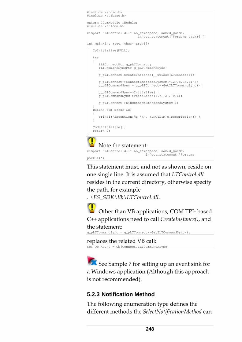
#include <stdio.h> #include <atlbase.h> extern CComModule _Module; #include <atlcom.h> #import "LTControl.dll" no_namespace, named_guids, inject_statement("#pragma pack(4)") int main(int argc, char* argv[]) { CoInitialize(NULL); try { ILTConnectPtr g_pLTConnect; ILTCommandSyncPtr g_pLTCommandSync; g_pLTConnect.CreateInstance(__uuidof(LTConnect)); g_pLTConnect->ConnectEmbeddedSystem("127.8.34.61"); g_pLTCommandSync = g_p LTConnect->GetILTCommandSync(); g_pLTCommandSync->Initialize(); g_pLTCommandSync->PointLaser(1.7, 2., 0.6); g_pLTConnect->DisconnectEmbeddedSystem(); } catch(_com_error &e) { printf("Exception:%s \n", (LPCTSTR)e.Description()); } CoUninitialize(); return 0; }
Note the statement: #import "LTControl.dll" no_namespace, named_guids, inject_statement("#pragma pack(4)")
This statement must, and not as shown, reside on one ll resides in the current directory, otherwise specify the p..\ES_SDK\lib\LTControl.dll.
single line. It is assumed that LTControl.d
ath, for example
Other than VB applications, COM TPI- based C++ the sg_pLTC
applications need to call CreateInstance(), and tatement: ommandSync = g_pLTConnect->GetILTCommandSync();
replaSet Ob
ces the related VB call: jAsync = ObjConnect.ILTCommandAsync
See Sample 7 for setting up an event sink for a Wiis no 5.2.3The diffe
ndows application (Although this approach t recommended).
Notification Method following enumeration type defines the rent methods the SelectNotificationMethod can
248
take. Only one of these methods can be active at a time be cavalu
. Therefore, SelectNotificationMethod shouldlled only once with one of the following
es: enum LTC_NotifyMethod { _NM_None, // No notification (using nothingLTC else but // synchronous calls) LTC_NM_Event, // notify through connection point interfaces // (Events) LTC_NM_WM_CopyData, // notify through copydata and pass data // directly with message LTC_NM_WM_Notify, // notify through WM message and pass only size // through lParam };
•
ld be
nc and async he
ethod method should be
e arrived data
indow that gets the message must be passed through
r
LTC_NM_None In combination with the synchronous interface, neither events nor Windows messages are sent. Hence neither a continuous measurement nor trapping error events (beam broken etc.) is possible. The targetHandle and cookie of the SelectNotificationMethod method shouzero.
• LTC_NM_Event: Events are used to notify the client on asynchronous answers (syinterface). The targetHandle and cookie of tSelectNotificationMzero.
• LTC_NM_WM_CopyData The client is notified by a WM_COPYDATAmessage upon data arrival. Thblock is transferred with the message. See Win32 API documentation on WM_COPYDATA for details. The handle of the w
targetHandle. If there are multiple LTControlinstances (more than one tracker), the call ofSelectNotificationMethod for each LTControl instance must get a different cookie, in ordeto identify incoming messages with the respective tracker. The number of cookies is
249
unlimited. They are passed to the client through the pCopyDataStruct → dwData member. The transferred data needs to be interpreted by using the structures defined
The client is notified by a user-defined r a 'registered
ie is available as wParam at
h targetHandle. e size of the block is passed with the
lParam). The GetData()
ined as
in the C TPI as masks.
• LTC_NM_WM_Notify
message, WM_USER+XXX omessage'. The CopyData method has one cookie for each tracker. Other methods havecookies only if there is more than one tracker. The cookthe client application. The handle of the window that gets the message must be passed througOnly thmessage (throughmethod of the LTConnect interface must be called in order to retrieve the data.
The method SelectNotificationMethod is deffollows: HRESULT SelectNotificationMethod( [in] LTC_NotifyMethod notifyMethod, [in] long targetHandle, [in] long cookie);
Implementing an event sink in a Windows
ed. S
ost omplicated, the 'LTC_NM_Event' method is
return
est these return codes,
application, using the LTC_NM_WM_COPYDATA or LTC_NM_WM_Notify is recommended.
Using 'LTC_NM_Event', although possible (as Sample 7 shows), is complicat
ample 7 demonstrates all different approaches with disabled code sections. Although mcenabled as the default.
5.2.4 Exceptions and Return Types All methods/interfaces have a HRESULTtype, as per COM design. Applications are usually not required to t
250
since method failures are signaled by exceptions. r information
ing describing the reason for These exceptions come with erro(mainly a text strfailure)
Exceptions must be 'caught'. Unhandled exceptions lead to program aborts.
Exception Handling in Visual Basic
t before the first
ror GoTo ErrorHandler
Each VB function calling interface methods must provide the following statemencall: On Er
At the bottom of the function, before the EndSub llowing (minimal) code block
it Sub
statement, the fomust be inserted: ExErrorHandler: MsgBox (Err.Description)
Err.Description is only a default minimal error text (always in English). Of com
urse any other error essage of your choice can be displayed.
her than a text, the To get the error number raterror handler would may look as follows: Exit Sub ErrorHandler: M sgBox (CStr("Error occurred: ") & ObjConnect.LastResultStatus)
Do not use the term 'Err.Number'. This is a COM eless to the application.
tively, the number of the last error e
error number, which is us
Alterna(lastResultStatus) can also be retrieved with thcommand 'GetSystemStatus'.
Additional or dican be inserted after the ErrorHandler label
Exception Handling in C++
In C++ applications, exception handlingperformed through 'try/catch' statements. Thecaught
fferent error handling code .
is
exception is of type _com_error.
251

Se Win32API COM documportError Interface.
e entation for details of ISuptry { objSync->FindReflector(5.0, true); } catch(_com_error &e) { MessageBox("Exception:%s", (LPCTSTR)e.Description()); }
An e.Description() returns the appropriate string e failure. 'Try/catch'
nested, and are required when
than the (default) text is of interest, use the property
bjConnect.LastResultStatus.
that describes the reason of thstatements may bequeuing several synchronous commands within one C++ function.
If the error number rather
otry { bjSync->FindRefo lector(5.0, true); } catch(_com_error &e) { MessageBox("Error Nr:%d", objConnect.LastResultStatus); }
Alternatively, the number of the last error (lastResultStatus) can also be retrieved with the com
a turn status
The necessary exception handling precludes ev
mand 'GetSystemStatus'.
Ev luating the Re
aluation of the return status.
Certain constellations such as S_FALSE urn value require an evaluation. ret
Types of 'success' return: S_OK S_FALSE
S_OK is returned for ordinary success cases.
Commands that return a status of type RaESS_ K. This means thaspecified tolerance. As a warning no exception
il ppropriate status
Out of nge OK- example: _RS_Parameter1OutOfRangeOK returns FALSE in case of Out Of Range Ot the command succeeded, but is out of
w l be thrown, but a
252
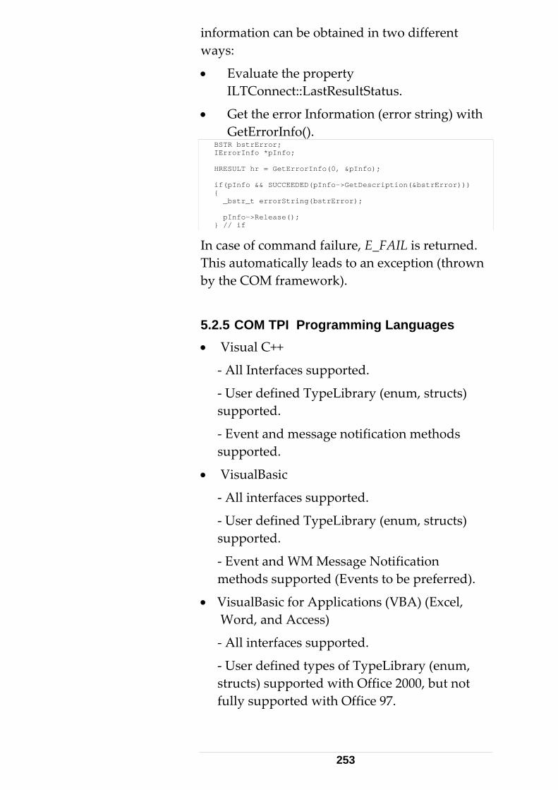
information can be obtained in two different wa
• rty
• with
ys:
Evaluate the propeILTConnect::LastResultStatus.
Get the error Information (error string)GetErrorInfo().
BSTR bstrError; IErrorInfo *pInfo; HRESULT hr = GetErrorInfo(0, &pInfo); if(pInfo && SUCCEEDED(pInfo->GetDescription(&bstrError))) { _bstr_t errorString(bstrError); pInfo->Release(); } // if
I .
Languages
ibrary (enum, structs) supported.
-
and Access)
supported.
- User defined types of TypeLibrary (enum, structs) supported with Office 2000, but not fully supported with Office 97.
n case of command failure, E_FAIL is returnedThis automatically leads to an exception (thrown by the COM framework).
5.2.5 COM TPI Programming • Visual C++
- All Interfaces supported.
- User defined TypeLibrary (enum, structs) supported.
- Event and message notification methodssupported.
• VisualBasic
- All interfaces supported.
- User defined TypeL
Event and WM Message Notification methods supported (Events to be preferred).
• VisualBasic for Applications (VBA) (Excel, Word,
- All interfaces
253
- Event notification methods supported (WM ot supported).
C# and VB .NET
- User defined types of TypeLibrary (enum,
- Event notification methods supported
- Scripting Languages (VBS, JavaScript)
COM
Could be achieved by providing a COM Idispatch wrapper around the LTControls
Messages n
•
- All interfaces supported.
structs) supported
Currently not supported. Support of these languages requires 'Dual' or IDispatchinterfaces.
custom interfaces.
It is recommended to use Office 2000 for TPI VBA Programming. Office 97 (Excel 97, Word lacks UDT and contains some bugs that mdevelopment of TPI clients virtually impossas soon as events are involved.
Interface methods using 'struct' parameters, which do not support user-defined types (Office 97 only), cannot be used from within
97) ake
ible,
VBA. However, functions are available based on basic data types, as a work around.
Older versions of VBA may lack support of enum-type symbols, so they need to be passed as 4 Byte (long) values. Therefore the numerical
representation of particular enum values must beknown. In C-language TPI, these values are explicitly enumerated.
See TPI _C_API_Def.h in SDK, for enum definitions. A type library viewer will also show the numerical values.
Example Enum definition:
254

enum ES_TrackerTemperatureRange { ES_TR_Low, ES_TR_Medium, ES_TR_High, };
ES_ TR_Low =0, TR_Medium=1 and ES_TR_High=2
• Command in a VB application ObjSync.SetTemperatureRange ES_TR_High
• Command in (old version) VBA ObjSync.SetTemperatureRange 2
Only use the second approach if the first one isnot supportedenvironment.
5.2.6 Proper Interface Selection Unlike the C and C++ TPI, the COM TPI is a Dlibrary and not an include file. This DLL provian easy to use programming interface for the Tracker Server. This makes it suitable for programmers with minimal programming expertise to design simple tracker applicationsThe COM TPI also opens doors to programlanguages such
with your programming
LL des
. ming
as VisualBasic, Delphi, VB.NET,
ver C++ TPI, the Win32 Sockets 2.0 API and VC++ ATL. The
red to deal with TCP/IP communication libraries or system programming interfaces.
VBA (Office Macro Languages) etc.
The interface is made- up of a so-called COM object. It is designed as an ATL DLL COM server. The DLL is named 'LTControl.dll' and comes as part of the emScon SDK. LTControl provides built-in TCP/IP communication.
The LTControl COM-object DLL is based on the tracker ser
LTControl.dll is, in a sense, a Tracker Server C++ Client. However it acts as Server from applications (based on LTControl) point of view.
The programmer is not requi
255
The high-level TPI supports both synchronous nd asynchronous methods.
Note: Using the ‘synchronous’ interface may
actions cannot be interrupOrientToGravity..), as thiasynchronous communic
.B.
m to the synchronous
t g is more hr
h m
se 'inte
Librar ontrol.tlb is also
LTControl is strictly based on the C++- programming
terface.
a
provide some convenient properties. However, there are also some disadvantages: Long- taking
ted (FindReflector, s is possible with ation on using
‘StopMeasurement’ command. Synchronous commands also imply potential timeouts. They also offer less transparency and control to the programmer. For highly professional applications, we recommend programming in C++ or C#, hence using the C++ or C# interface directly (which are asynchronous be design)interface for VB/VBA/Vprogramming, we recomasynchronous COM interface
If using the COM NET/C# application
end to prefer the
interface! Although cliendifficult with the asyncprogrammer has muctransparency.
- programminonous interface, the ore control and
COM objects expoType-Library, which is im
rfaces', described by a plicitly included in the
y LTCDLL. A pure Typeavailable, although not really needed. This High-level interface does not provide any additional functions (in terms of Tracker Server controlling functions). TPI, with a high-level, convenientin
COM interfaces work well together wiVisual Basic, Delphi and Office Macro
th
rogramming languages (VBA) on the Win32
r those types of languages.
pplatform, while using the emScon C or C++ interface is difficult fo
256

COM vs. C/C++ Programming
Advantages Disadvantages
No include-file to deal Comes as a DLL (ATwith on using COM TPI. COM component). Its
L
source code is not public, which complicates application debugging.
No TCP/IP library or function needs to be
Is limited to Win32
provided. All these functions are built-in. Only the IP address of the tracker server needs to be provided.
platforms.
The COM interface offers both synchronous and asynchronous
Due to COM overhead, the performance maffected.
communication support.
ay be
There are wide varieties of notification methods for arrival data when using asynchronous communication.
Since TCP/IP communication is builin, there are no 'tuning' possibilities.
t-
Supports various programming languages.Easy to use due to support of 'IntelliSense' for Microsoft Visual and
The component needs tobe registered on the cliePC.
Office programming tools.
nt
Interfaces and Notification Methods
See chapter 'COM Interface' for more information on the interfaces provided.
5.2.7 Type- Library In order to get detailed information about the Interfaces (including data types, properties,
257

methods and events) exposed by a COM object, a COM viewer may be used. Visual Studio offers such a viewer: The OLE/COM Object Viewer can be launched from the Tools menu of VC++.
.
5.2.8 COM TPI Reference The type library of a COM object can be seen as Interface Refe
Listing all the methods redundantly in this manual would
The type libraenvironment to provide 'IntelliSense' support. That is, the development environment supports the programmparameters in
The method names of the COM TPI partly differ from those of the C++ interface (Although most of them – especially the 'Set/Get' functions – are named accordingly). This 'inconsistency' comes from the high- level approach of certain methods. However, by viewing the list of available functions (type- library, Intellisense), it is quite easy to find the proper methods and their relatives to the C / C++ interface (where the parameters are described).
Note that asynchronous methods never return any data. Data is returned through events in these cases. On the other hand, synchronous methods always return the result data (if any) as
n servsynchronous and asynchronous approach.
File > View Type Lib > LTControl.dll or LTControl.tlb
rence.
not make sense.
ry enables a development
er in selecting methods and an active manner.
parameters.
Co cerning input parameters (sent to the trackerer), there is no difference between the
258

5.2.9COM objects must be registered on the
pl ed.
LTControl.dll Installation t PC
(both developer and customer PCs
ocated in the all
ll from the Start/Run menu of the
Registering COM Objects
ap ication PC before they can be us
• Register LTControl.dll on the clien
).
• If LTControl.dll is lC:\WINNT\system32 directory, cRegsvr32 C:\WINNT\system32\LTControl.d
explorer task-bar.
The LTControl.dll does not ,
trol.dll succeeded'.
0000007e' most
L.dll as escribed below. After that, repeat
A•
indows system/system32 directory OR to
depend on any other custom DLLit can be registered anywhere. The Windows system directory is the common location.
• A message box appears confirming registration – 'Registering of LTCon
• A message such as: Error 'Load Library failed, error 0xlikely indicates that the PC lacks a correct ATL.dll installation (missing, wrong version or not registered). In this case, first install ATdregistering of LTControl.dll.
TL.dll Installation Copy Atl.dll from ES SDK 'Lib' directory to
WLTControl.dll directory. Unicode version for WinNT/Win2000. ANSI version for Win9x/Win ME.
259
See properties of ATL.dll for operating systems supported.
Register Atl.dll – Regsvr32.exe <path>\Atl.dll.
Repeat registration of LTControl.dll.
.2.10 Synchronous versus synchronous Interface
•
•
5AWhen designing a client application using the Lsu
Da
• rn hile the
• is much easier. Handling Data-Arrival
or Notifications is not required (except in
• nchronous interface and the events
ent), an
but in
event sink is not required and the WithEvents
message handlers and not event handlers, in this case.
• With the synchronous interface, some answers remain asynchronous by their nature - continuous measurement packets, Reflectors and error answers
TControl COM component, either the ynchronous or asynchronous interface can be sed.
ifferences between the synchronous and synchronous interface.
The functions of the synchronous interface do not retu before the task is completed, wasynchronous functions do so (see C/C++-TPI).
In general, programming with synchronous functionsEvents some special cases).
With the asynotification (that is, calling SelectNotificationMethod with LTC_NM_EvEvent- Sink must be implemented. In VB, this is done by defining the WithEvents keyword, C++ this is a bit more complicated. In addition, the appropriate event handlers must be implemented. With any other notification mechanism, the
keyword must be removed. Implement Windows
260

(these may partly occur non-command related,
ands, events or cations must still be caught - See former
ragraph. Any other notification mechanism the WithEvents
ord must be removed. In this case, do not
must be implemented instead.
• – a d p e
•
5.2.
• D
r in
for example beam broken). With synchronous commnotifipadoes not need an event sink, andkeywimplement event handlers; appropriate Windows message handlers
Using both interfaces in the same LTConnect instance lthough possible – usually makes nosense an artly leads to duplicate answers. Usof both interfaces within one and the same application is therefore not recommended.
5.2.11 Multi- Tracker Applications On multi tracker (multi tracker server) systems, create a separate instance of LTConnect for each tracker.
12 Visual Basic Boolean variable
evaluation o not test explicitly against the VB keyword
'True', if using the Get<FunctionName>Ex methods of the LTControl, for those commands returning Boolean data within their result structure. This is because the Boolean membethese structures, if true, is one (1). However, the VB keyword 'True' evaluates to (-1). Always test the variable directly, or against 'Not False'.
261

Example ObjSync.GetContinuousDistanceModeParamsEx dataout If (dataout.bUseRegion) Then MsgBox "bUseRegion is True" End If or If Not (dataout.bUseRegion = False) Then MsgBox "bUseRegion is True" End If are both correct. However, the following would evaluate to a wrong result: If (dataout.bUseRegion = True) Then MsgBox "bUseRegion is True" ‘ No message even flag true! End If
5.2.13 Reading Data Blocks with Visual Basic
n
also be ported to VB. Events ith unique events for
almost every type of arrival data (especially when these
e
Arrival data reading with C++, as shown i'Handling Data Arrival – Continuous Measurements', canfor VB are used here, w
using the asynchronous interface). Most ofpass their results through basic data typparameters.
See chapter 'Handling Data Arrival – Continuous Measurements'
Message notification methods with VB are not demonstrated here. However, there are some exceptions where the data must be retrieved explicitly upon an incoming event. These types of events can be
ng
The code below shows an implementation of the It
eceived. This handler does some diagnostics – checks whether the size of read data complies
identified by the DataReady term in their names. The continuous measurement events are amothese.
ContinuousPointMeasDataReady() event handler. does not demonstrate the processing of the data r
262

with the passed parameter. If OK, the size is displayed, otherwise
B
an error message is shown.
y calling the ObjConnectGetData() function, the
nd
not
arrived data (that caused the event) is being read into a local buffer. The application interprets aprocesses the data. In order to get the measurement values, loop through the array and interpret the array elements with MeasValueT (shown here).
VB may not be the right choice to process (high rate) continuous measurements, especially when running the interpreter. The VB project must be compiled first. Private Sub ObjAsync_ContinuousPointMeasDataReady( _ ByVal resultsTotal As Long, _ ByVal bytesTotal As Long) Dim data As Variant Dim tp As VbVarType Dim sz As Long ObjConnect.GetData data tp = VarType(data) ' type; we expect a Byte arryay If (tp = vbArray + vbByte) Then ' Byte Array sz = UBound(data) + 1 ' index is zero based! If (bytesTotal = sz) Then MsgBox sz 'display # of bytes received Else MsgBox CStr("Unexpected size:") & sz _ & CStr(", expected:") & bytesTotal End If End If End Sub
It is not necessary to read data here (with GetData). Answers may be filtered out and othose data pack
nly ets of interest can be read.
herwise no notification w l
The principles shown here also apply to message handlers, if one of the message notification me
With TCP/IP data must be read at socket level (see previous samples) ot
i l arrive again.
chanisms is selected.
See chapter 'Answers from Tracker Server' on how to mask/evaluate incoming data blocks.
263

5.2.1 t Exce The with
Ac e ms arewithparameters cannot be used. VBA that comes with
h limitations.
4 VBA Macro-Language Suppor
l, Word, Access
LTControl COM component can also be used VBA (Visual Basic for Applications), the
built-in Macro language of MS Excel, Word and c ss – with the exception that structs and enu not fully supported with VBA that comes
Office 97. 'Ex' functions that take struct
Office 2000 no longer has suc
It is highly recommended to use Office 2000 or hOffice 97 (Excel 97/Word 97) - apart from a missing UDT - contain some bugs that make development of Tracker Server clients virtually impobug savinFor tTPI-SDK are in Excel 2000 format. They may run withany changes are saved. Always maintain a safe (readThe following remarks only apply to Office 97 progordi
UserVisu
• lo tSwithin Visual Basic. VBA claims an error Aue
igher for Tracker Server VBA Programming.
ssible, as soon as events are involved. This leads to a completely corrupted file upon file g, after an event has arrived.
his reason, Excel samples delivered with the
Excel 97 , but may be destroyed as soon as
-only) copy.
ramming (Office 2000 VBA behaves as nary VB).
-defined Types, the Differences between al Basic and VBA97
Both allow defining user-defined structs cally. However, those structs exported by
he LTControl (such as PacketHeaderT, ingleMeasResultT) are only recognized from
tomation type not supported if declaring, for xample, a variable like:
264
Dim val As SingleMeasResultT // works with VB, but not VBA97
• pported by VBA97. The cEnums are not suompiler does not know the keyword Enum.
User-defined enums cannot be defined locally, although this works with ordinary Visual Basic. It is also not possible to use enum- type variables that are exported by the LTControl. Declaration as follows are not possible in VBA97:
h VB, but not VBA97 Dim cmd as ES_Command // works wit
• When implementing an EventHandler that rs in Visual Basic will
llows (only function header has enum-type paramete
ad as foreshown):
Private Sub CommandSync_ErrorEvent(_ ByVal command As LTCONTROLLib.ES_Command,_ ByVal status As LTCONTROLLib.ES_ResultStatus)
• When doing the same in VBA97 it will read ws: mandSync_ErrorEvent(ByVal command As Long, _
as folloPrivate Sub Com ByVal status As Long)
Visual Basic keeps the enum type information and recognizes the parameters
pecific to VBA, it also exists in VB. There are two different
type parameters, for example, call SetMeasurementMode the same
ousDistance);
with their correct enum- types, while VBA just passes them as long parameters. However, the symbols of the enum values are correctly recognized, although not checked by the compiler for correct typing (which can lead to errors, which are difficult to find). This problem is not s
situations where enums and their value- symbols affect the interface:
Method takes enum
way for both VB and VBA: ICommandSync::SetMeasurementMode(ES_MM_Continu
1. ES_MM_ContinuousDistance will be correctly recognized as having the value '2' (see enum definition).
2. Correct typing of values: VB as well as the VBA interpreter will not recognize typing
265
errors in enum symbols here. However, bVB and VBA p
oth rovide 'IntelliSense', providing
for a selection from a list rather than having to type them in.
n
A):
3. Event handlers, as we have seen above, pass enums as long values in VBA. The incoming values can be tested against enum symbols. In an event handler, the followingcode might be typical (example ErrorEvent iVB
Private Sub CommandSync_ErrorEvent(ByVal command As Long, _ ByVal status As Long) If (command = ES_C_Initialize) Then ' do something End If If (status = ES_RS_NoTPFound) Then ' do something End If End Sub
Use extreme caution while typing the symbwith VBA 97. No 'IntelliSense'
ols support is
•
•
• event functions has struct parameters (technical restriction), and have, therefore, no restriction with VBA97.
5.2.15 Continuous measurements and VBA Events of continuous measurements do not directly pass the data.
available.
Summary There is no problem with enums and VBA97. It is just a potential error source due to missing type checking.
Structs (unless locally defined) are not supported in VBA97. LTControl always offers an alternativeto those functions returning struct parameters.
None of the
See chapter 'Handling Data Arrival – Continuous Measurements ' for details.
Handling continuous measurements within VBA requires care. Events can be 'subscribed' with the
266

WithEvent keyword and pending data can be read with GetData(), as shown in:
See chapter 'Reading Data Blocks with Visual ' for details. Basic
Masking Data The unavailability of (LTControl) structures
he data. With the byte-layout appropriate bytes can be
t and exceeds the typical pertise.
ctions, data blocks can s
f pointer type-casts:
prevents masking tof the data blocks theextracted 'manually' and assigned to basic dattypes.
a
This is not convenienExcel programmer's ex
Even with VB, although structs are available, masking data is not that easy as in C++. By providing some helper funbe copied to appropriate struct parameterinstead oILTConnect::ContinuousDataGetHeaderInfo() ILTConnect::ContinuousPointGetAt() ILTConnect::ContinuousPoint2GetAt() ILTConnect::Continuous6DDataGetAt()
This allows extracting information of interest from data blocks of type ES_DT_MultiMeasResult, ES_DT_MultiMeasResult2 and ES_DT_Multi6DMeasResult.
tation, with comments, of tinuousPointMeasDataReady event handler
that demonstrates usage of these functions reads
A VB (VBA) implementhe Con
as follows:
267
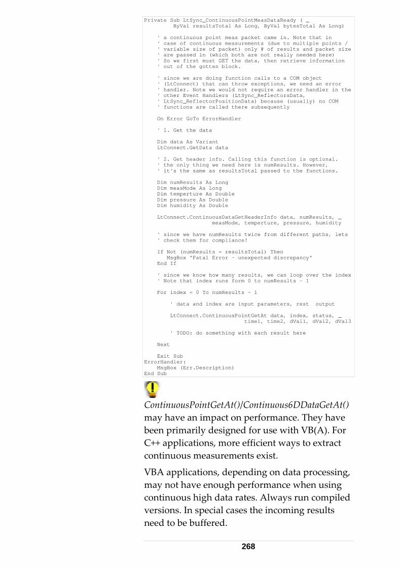
Private Sub LtSync_ContinuousPointMeasDataReady ( _ ByVal resultsTotal As Long, ByVal bytesTotal As Long) ' a continuous point meas packet came in. Note that in ' case of continuous measurements (due to multiple points / ' variable size of packet) only # of results and packet size ' are passed in (which both are not really needed here) ' So we first must GET the data, then retrieve information ' out of the gotten block. ' since we are doing function calls to a COM object ' (LtConnect) that can throw exceptions, we need an error ' handler. Note we would not require an error handler in the ' other Event Handlers (LtSync_ReflectorsData, ' LtSync_ReflectorPositionData) because (usually) no COM ' functions are called there subsequently On Error GoTo ErrorHandler ' 1. Get the data Dim data As Variant LtConnect.GetData data ' 2. Get header info. Calling this function is optional. ' the only thing we need here is numResults. However, ' it's the same as resultsTotal passed to the functions. Dim numResults As Long Dim measMode As Long Dim temperture As Double Dim pressure As Double Dim humidity As Double LtConnect.ContinuousDataGetHeaderInfo data, numResults, _ measMode, temperture, pressure, humidity ' since we have numResults twice from different paths, lets ' check them for compliance! If Not (numResults = resultsTotal) Then MsgBox "Fatal Error - unexpected discrepancy" End If ' since we know how many results, we can loop over the index ' Note that index runs form 0 to numResults - 1 For index = 0 To numResults - 1 ' data and index are input parameters, rest output LtConnect.ContinuousPointGetAt data, index, status, _ time1, time2, dVal1, dVal2, dVal3 ' TODO: do something with each result here Next Exit Sub ErrorHandler: MsgBox (Err.Description) End Sub
ContinuousPointGetAt()/Continuous6DDataGetAt() may have an impact on performance. They have been primarily designed for use with VB(A). For C++ applications, more efficient ways to extract continuous measurements exist.
ata processing, ay not have enough performance when using
versions. In special cases the incoming results need to be buffered.
VBA applications, depending on dmcontinuous high data rates. Always run compiled
268

Use of values instead of symbols, in Visual Basic, voids the problem of typing incorrect enum a
symbols, which cause errors difficult to detect.
A complete .tlh file is automatically generated when importing LTControl.tlb into a
ages VBS (Visual Basic d
m interfaces (dual interfaces) have the ame disadvantage as IDispatch – lack of
i
No
(Beexceptions may not be raised in the client applicaDo not set this property for Microsoft clients (VB, C++, C#, Excel..), that is, leave its default value 0.
For further information, see commented code in Sample 20 (LtcDelphiClient), where this property
set to 1.
VC++ project.
5.2.16 Scripting Language Support Pure scripting languScript), JavaScript etc. are currently not supporteby the LTControl COM component.
This would require IDispatch interfaces rather than custom interfaces. Combinations of IDispatch and custosperformance.
5.2.17 Exception Handling for Non- M crosoft Clients The emScon LTControl COM interface also supports Windows application development with
n- Microsoft Tools, such as Borland Delphi.
For such applications, it may be necessary to set the property 'LTConnect::ExceptionHandlingPolicy' to 1
fore connecting to emScon server). Otherwise
tion.
is
Example (Delphi): LtcConnect.Set_ExceptionHandlingPolicy(1);
269

5.3 COM TPI Samples 5.3.1 Sample 5 This chapter is related to the 'Sample5' folder othe emScon SDK Samples.
S
f
ample 5 (LtcVBClient) comes as an LTControl-lient.
Note: 'LTControl.dll' must be correctly registered b
S
If LTControl is correctly registered, ctly be opened with
Visual Basic Studio. It should be ready to compile and run.
In order to create a Sample 5- type application f
-
- t as LtcVBClient.vbp (or use any name
Choose menu Project > References.
for the
based Visual Basic emScon C
efore proceeding.
ee chapter 'LTControl.dll Installation' for details.
'LtcVBClient.vbp' can dire
rom scratch, follow the steps:
Launch Visual Basic 6.0, choose New Project > Standard exe. Click OK.
Save the default Form1 as LtcVBClient.frm andthe projecof your choice).
-
- In the 'Available References' list, lookentry 'LTControl 2.x Type Library' and check the box in front of.
Ensure that the file path at the bottom of the dialog matches the control's registration location. Otherwise browse for location. Finally click OK.
the correct
ol.dll, TL-type COM object, can also be
Accessing COM Interfaces
Other than ActiveX (OCX) controls, LTContrwhich is an A
270

us for non-window basedple, it will also support, pure C-clients
sole applications).
ontrol control object to the VB application (as ActiveX controls require).
ed applications. For exam(con
It is neither necessary nor possible to place an LTC Form
• To avari'General' declaration part of the code behind the app'NewDim Ob
Interface Variable Declaration
ccess LTControl's interfaces, an object able of type LTConnect is needed in the
lication form. Note the essential keyword ':
jConnect As New LTConnect
• Just after that, declare an object for each one of
synchronous or an asynchronous oth, as
ata arrivals and other
the shown types. Note the keyword 'WithEvents'.(In a real application, only one - either ainterface – should be declared. Declaring bdone here for demonstration purposes, could result in some duplicate dconfusion). Dim WithEvents ObjAsync As LTCommandAsync Dim WithEvents ObjSync As LTCommandSync
Connecting / Disconnecting to Server and Initialization Tasks
A variable of LTConnect object is always required, ication, only one of the
is
, LTCommandAsync or
ommandAsync es act like 'pointers'. These 'pointers' must
b
whereas, in a real applLTCommandSync or LTCommandAsync objects required. Depending on the selected notification mechanismLTCommandSync is to be declared with/without event support (WithEvents keyword).
The LTCommandSvariabl
ync and LTC
e initialized with the related properties of LTConnect:
271

• Just after calling the ObjConnect.ConnectEmbeddedSystem() method, initialize the 'pointers' as shown
exceptions in case of
se (On Error Goto...). It's ghly recommended to wrap every COM-
h an 'On Error et
ore the
Here is a 'stripped down' version of the Samples' 'Connect' handler. It shows only the essential ste
below (In the sample, this is done in the event handler of the 'Connect' button). Further, the notification method must be selected (SelectNotificationMethod ()).
COM methods throw•failure. The sample code shown below shows how to handle thehimethod calling function witGot Error Handler' statement. Do not forgthe 'Exit Sub' statement just bef'ErrorHandler' label.
ps. See Sample code for a more sophisticated 'Connect' handler (with getting the IP address from user- interface etc.) Private Sub Button_Connect_Click() On Error goo error handler ObjConnect.ConnectEmbeddedSystem "192.168.0.1", 700 ' This is important if events want to be received electrification's LTC_NM_Event, 0, 0 ' NEVER FORGET to initialize the objects this way !!!!! Set ObjSync = Connecticut's Set ObjAsync = disconnectedness's Exit Sub ErrorHandler: MsgBox (Err.Description) End Sub
The End statement in the error case exits the application, when connection to the tracker has failed.
To disconnect from Tracker Server use a h
server
andler as shown below (Only essential code is shown): Private Sub Button_Disconnect_Click() disconnectednesses End Sub
See Sample 7 for an explanation of the call 'electrification's LTC_NM_Event, 0, 0'.
272

However, for VisualBasic applications, it usually ense to call this method with
n handler ompleted with the following code:
does not make sother parameters.
Implementing Synchronous Commands
Add a button named InitSync. The buttoshould be cPrivate Sub InitSync_Click() On Error goo error handler ObjSync.Initialize Exit Sub ErrorHandler: MsgBox (Err.Description) End Sub
Since this is a synchronous call:
• ObjSync.Initialize will not return before the tracker has finished initializing.
ached until
esides in the InitSync
tton) handler, otherwise the pplication will terminate in case of an error
n/Handler Measure Single Point ent the handler as shown below. It is
erver is set to 'stationary'
essage box (only x, y and z are shown).
• The Exit Sub statement will not be reinitialization is finished. A real application would at least display an hourglass cursor while the program rfunction.
The error handler should be implemented in every command (bua(unhanded exception).
Add another Buttoand implempresumed the tracker swhen triggering this command (In Sample 5 code,this is ensured in the Button_Connect_Click() handler'. Of course the laser beam must be attached to a reflector in order to perform this command successfully. The result – since a synchronous answer – can be shown directly in a m
273

Private Sub StartMeas_Click() Dim x As Double Dim y As Double Dim z As Double Dim d As Double 'd is a dummy variable Dim b As Boolean On Error goo error handler ObjSync.MeasureStationaryPoint x, y, z, d, d, _ d, d, d, d, d, d, _ d, d, d, d, d, d, b MsgBox (x & CStr(" , ") & y & CStr(" , ") & z) Exit Sub ErrorHandler: MsgBox (Err.Description) End Sub
If this command was an asynchronous call, it would not be possible to display the result withthis functio
in n. A result display is performed in the
appropriate asynchronous answer handler.
t ith the
t
For more details, refer to Sample 5 source code. Implementing Asynchronous Commands
Visual Basic with 'IntelliSense' provides supporfor the available functions of an interface wfunction parameters.
Add a button named InitAsync.
The command handler should be completed with he following code:
Private Sub InitAsync_Click() On Error goo error handler ObjAsync.Initialize Exit Sub error handler: MsgBox (Err.Description) End Sub
In contrast to the synchronous initialize function,
inse
Catching Events and Messages
For asbe handled by some event mechanism. This could bebound, registered, WM_COPYDATA).
this one does not stop at the Initialize() function, Exit Sub is reached immediately. When tracker
itialization is done, a notification or event is nt.
ynchronous commands, the answers must
Events, Windows Messages (custom window-
274
For Visual Basic, Events are the right choice. The
_s his mechanism for a Visual Basic application, we prd
D
event mechanism is provided by the ILTCommandAsyncEvents interface, which is a ubsidiary of ILTCommandAsync. To activate t
ovided the keyword WithEvents upon the eclaration:
im WithEvents ObjAsync As LTCommandAsync
When no requirements for catching events exists, omit the WithEvents keywords in order to save overhead.
Not only the asynchronous interface – where so
erface,
nts and other ulti- answer' results (such as results to a
ssages be
d synchronous by their nature.
absolutely crucial – has an Event interface. Althe synchronous interface has an Event int_ILTCommandSyncEvents. It is required for receiving continuous measureme'm'GetReflectors' call), as well as for error me(such as beam broken events), which cannothandle
Events are one of the notificatiothWindows messages for asynchronous notifications the keyword WithEvents becobsolete. Windows messamay be more appropriate for VC++ clients and will be discussed later. For Visu
n methods of e LT Control. When alternatively using
omes ges (instead of Events)
alBasic, Events
ion
is
ill be activated.
are always the right choice.
• The application must declare what notificatmechanism to use. We did this with the statement shown below. Without calling thfunction in the initialization part of the application, no notification mechanism w
See remarks on continuous measurement in chapter 'Handling Data Arrival – Continuous Measurements'.
275

electrification's LTC_NM_Event, 0, 0
• As soon as the WithEvents keyword is declthe ObjAsync object (or whatever the variablecalled) is listed in the top left list box of the Form's source code window.
ared, is
Just as an experiment: Remove WithEvents and save the code – the list entry will vanish
• If ObjAsync is selected in the list box, a lavailable e
.
ist of all vent handlers is shown in the right
drop-down list.
for an event
erate a function vent. Do this and
me with a
• To generate the code frameworkhandler, select it from the right list .
Selecting ErrorEvent will gennamed ObjAsync_ErrorEcomplete the generated function framessage box to read as follows: Private Sub ObjSync_ErrorEvent( _ ByVal command As LTCONTROLLib.ES_Command, _ ByVal status As LTCONTROLLib.ES_ResultStatus) MsgBox (command & CStr(" , ") & status) End Sub
This event handler will now be triggered, for example on a Beam Broken Event. Note: The 6Dof part of the interface contasome event- types with a huge count of
ins
arameters. To mention ryProbeMeasData’, which is the most
e-library for signature).
p‘Stationaextreme with 49 parameters (!)
Such excessive parameter lists – depending on VB version - partly are beyond code- generating Wizards capability. Lines may be cut, which will lead to syntax errors (for generated code). In these cases, the cut lines need to be completed manually (see typ
276

Extended Synchronous Functions
asic data ata type parameters are
irement in order to use these functions with der versions of) VBA (Excel, Access…).
porting user-d data types (VC++, Visual Basic), having a
e provides a collection
h 'extended' functions.
nded functions,
ObjSync.MeasurStationaryPoint has 18 (btype) parameters. Basic da requ(olFor programming languages supdefinefunction with only one struct parameter would bmore convenient. LTControlof sucNote that such extended functions cannot be provided for Event handlers (Technical limitation)
One of these exteMeasureStationaryPointEx, is implemented in the sample: Private Sub StartMeasEx_Click() Dim result As SingleMeasResultT On Error goo error handler ObjSync. MeasureStationaryPointEx result ' display the result MsgBox(result.packetInfo.status & CStr(" , ") & _ result.packetInfo.packetHeader.Type & _ CStr(" , ") & result.dVal1 & CStr(" , ") & _ result.dVal2 & CStr(" , ") & result.dVal3) Exit Sub ErrorHandler: MsgBox (Err.Description) End Sub
The data type SingleMeasResultT from the C-TPI is transparent through the COM interface. The VBapplication 'knows' this type, through its reference to the LTControl.
Remark
Do not test explicitly against the VB keyword rue', if using the Get<FunctionName>Ex methods
those commands returning
res –
evaluates to (-1).
'Tof the LTControl, for Boolean data within their result structure. This isbecause the Boolean member in these structuif true – are (1). However, the VB keyword 'True'
277
Always test the variable directly, or against 'Not lse'. Fa
ObjSync.GetContinuousDistanceModeParamsEx dataout
Example
If (dataout.bUseRegion) Then MsgBox "bUseRegion is True" End If or If Not (dataout.bUseRegion = False) Then MsgBox "bUseRegion is True" End If are both correct. However, the following would evaluate to a wrong result: If (dataout.bUseRegion = True) Then MsgBox "bUseRegion is True" ‘ No message even flag true! End If
Further details see 'Readme.txt' file in Samplfolder and code- comments in source files.
e 5
5.3.FC
k to atch asynchronous answers (continuous
inim
Refer to a COM book for further details.
nitial steps for a successful system start and accurate results, with some disabled code, which demonstrates all
ich may be more familiar to programmers than event ha
2 Sample 7 The LtcCPPClient provides a dialog- based MC++ application. It uses the synchronous interface, but also implements an event sincmeasurements and error events).
Programmers need to be familiar with ATL/COM order to understand the event sink plementation.
The LtcCPPClient covers all essential i
other variants of notification methods, wh
ndling.
See comments in source code.
The disadvantages of message notifications are: Message Notifications
278
•
• ck is passed w
•
'switch' statement with the ProcessData()
The result parameters cannot be received directly.
• There are only general messages for all types ofanswers.
Usually only the size of a data bloith the message.
The data block must be first read with GetData() (except for WM_COPYDATA) and then interpreted. Interpretation is done with a
sample code.
See chapter 'Handling Data Arrival – ntinuous Measurements '.
is sample also shows one of the features not
own to the system. It also demonstrates ntinuous measurements.
Co
Thshown so far: How to retrieve the reflectors knco
View the source code for details. Note that is code contains a relatively big overhead
rver specific part is not that dominant.
rmation that is displayed in list boxes, such as units, CS-type, is automatically read from the Tracker
as been actually selected.
Changing the items of one list box automatically creates a 'Set' for the newly selected item
thneeded for user interface issues. The Tracker Se
Source Code Description
• Info
Server upon startup. What is seen h
•
.
On changing units, CS-type etc., some
is d'.
•dependent information may vanish from the related edit fields to ensure consistency. Thisdue to the paradigm 'What you see is selecteDo a 'Get' to recover it, which can also be done by the application.
279

• On setting new values, the 'Set' command is automatically followed by a 'Get' (two beep
eps. They must be
sounds). The 'Get' is not required (only for testing and demonstration purpose).
• Reflectors are read upon client startup. Can be heard by characteristic beselected in the reflectors list box.
The GetRef'emergency' cases. If the client starts beforeTracker Server is ready and the client dishows up, but is not able to read the reflectoyet.
lectors button is only required in the
alog rs
•on selection. By changing the
() (all variants are an
plete).
• s owever,
methods can be activated by enabling the commented source co
The application is based on LTC_NM_Event notificatiparameter of SelectNotificationMethod in CCPPClientDlg::OnInitDialogprepared), a different notification method cbe activated. However, there is only an incomplete implementation of ProcessData() forthese alternate methods (reflector processing, for example, is not yet com
Only the LTC_NM_Event notification method ifully implemented in this sample. Hdata transfer also works with message methods. One or the other
de.
Only the last call of SelectNotificationMethis effectiv
od e (there should be only one call to this
function).
See chapter 'Handling Data Arrival – Continuous Measurements' for details on obtaining data in general and continuous measurements in particular.
280

Handling Data Arrival – Continuous Measurements
Continuous measurement streams are always onous. That is, even if only a
lemented (through which mmand may be s measurement packets
long. all the time.
s •
LTC_NM_Event as
TmmV
• Use one of the Windows Messages notification m S(dThese may be methods preferred with VC++ clients, especially if the programmer is not
hand, receiving Windows messages within VB a
• array. The rest of the
ay elements are padded
handled asynchrLTCommandSync is impthe Start Measurement coinvoked), the continuouwill arrive asynchronously.
A continuous measurement may last veryIt is not suitable to block execution
Methods to Catch PacketProvide a LTCommandSync object with a call to SelectNotificationMethod, with first parameter.
his setting allows catching the continuous easurement packets through the event echanism. This is especially convenient for isual Basic.
ethods. ee 'Sample 7' – where this method is shown isabled) in the source code.
familiar on setting up event sinks. On the other
pplication is permissible.
The MultiMeasResultT structure only covers the first item of the lNumberOfResults - 1-arrto the packet without gaps.
Continuous measurement packets mostly c ntain more than one measurem
ration through an array of measurements is cessary.
o ent value. Itene
• A code fragment, on how to process a continuous measurement packet using the event mechanism, is shown below. This is a client implementation,
281

stripped down and altered from sample 7, ofContinuousPointMeasDataReady event, whic
the h
_ILTCommandAsyncEvents interfaces Ready(long resultsTotal,
exists for both _ILTCommandSyncEvents and
void __stdcall OnContinuousPointData long bytesTotal) { CString s; VARIANT vt; VariantInit(&vt); if (m_pLTConnect == NULL) return; m_pLTConnect->GetData(&vt); MultiMeasResultT *pData = (MultiMeasResultT *)vt.parray->pvData; ASSERT(pData->lNumberOfResults == resultsTotal); for (int i = 0; i < pData->lNumberOfResults; i++) { s.Format(_T(" %.7lf, %.7lf, %.7lf"), pData->data[i].dVal1, pData->data[i].dVal2, pData->data[i].dVal3); // this is application dependent. May differ in your app m_pMainWnd->m_edit_Result.SetWindowText(s); } // for } // OnContinuousPointMeasDataReady()
• On using a Windows message notification method, LTC_NM_WM_Notify, it looks quite similar. However, with the event method there is a unique event function for just receiving continuous results. With message notify methods, all types of data packets come in through the same message handler. The data must be interpreted with a 'switch' statement. This is done in the ProcessData() function. Use of the CESAPIReceive class of the C++ interface is another possibility.
• The following implementation demonstrates receiving, not only data of continuous measurements, but also, any kind of data.
LRESULT CCPPClientDlg::OnNotifyMsg(WPARAM wParam, LPARAM lParam) { CString s; VARIANT vt; VariantInit(&vt); m_pLTConnect->GetData(&vt); // wParam = msg ID = cookie! ProcessData(vt.parray->pvData, wParam); return true; // return non-zero if msg handled }
- Activating this function calls SelectNotificationMethod() with the following parameters:
282

// cookie must be in the valid range for a user defined message m_pLTConnect->SelectNotificationMethod(LTC_NM_WM_Notify, (long)m_hWnd, MY_NOTIFY_MSG);
- The message ID (which also acts as a cookie here) is defined as:
#define MY_NOTIFY_MSG (WM_USER+99)
- Entry in the message map must exist as follows:
ON_MESSAGE(MY_NOTIFY_MSG, OnNotifyMsg)
Provide the ProcessData() subroutine. - Not every type of data packet is fully
d: implemente
283

void CCPPClientDlg::ProcessData(void *ptr, int nCookie) { CString s, s2; PacketHeaderT *pHeader = (PacketHeaderT*)ptr; switch (pHeader->type) { case ES_DT_MultiMeasResult: // most frequent ones on top { MultiMeasResultT *pData = (MultiMeasResultT *)ptr; for (int i = 0; i < pData->lNumberOfResults; i++) { s.Format(_T("%lf, %lf, %lf"), pData->data[i].dVal1, pData->data[i].dVal2, pData->data[i].dVal3); // do something with data // application dependent m_staticContMeas.SetWindowText(s); } // for } break; case ES_DT_Error: { ErrorResponseT *pCmdData = (ErrorResponseT *)ptr; s.Format(_T("error: command=%d, status=%d\n"), pCmdData->command, pCmdData->status); AfxMessageBox(s); } break; case ES_DT_SingleMeasResult: { SingleMeasResultT *pData = (SingleMeasResultT *)ptr; ASSERT(pData->measMode == ES_MM_Stationary); // TODO: do something with data } break; case ES_DT_ReflectorPosResult: { // Not implemented } break; case ES_DT_Command: break; // nothing to do default: Beep(100, 100); // all other data currently unhandled } // switch } // ProcessData()
For further details refer to the sample sourcecode.
Limitations for high frequency continuous
tions. ests have shown that under good conditions
rogram design), the LT
measurements (like loss of data) may occur due to hardware (LAN, PC performance) limitaT(LAN, PC, Client pControl is able to handle the maximum data rateof 1000 points per second, even through the eventnotification mechanism, which might have slightly less performance than the message
284

methods – Low performance of IDispatch Interfaces.
Known Bugs in ATL Event Sink Implementation There are currently two known bugs confirmed
Containers
s May Give Strange Values.
orkarounds provided in
comments in source files.
nt VBA- ce 97) is not
by Microsoft in VC++ 6.0 concerning event handlers.
- (Q237771): Events Fail in ATL when Enum Used as Event Parameter.
- (Q241810) IDispEventImpl Event Handler
Apply one of the wMSDN and in Sample 7 (file DataArrived.h) for a practical application of one of the workaroundsprovided.
Further details see 'Readme.txt' file in Sample 7 folder and code- 5.3.3 Sample 8 This sample works only with Excel 2000 and higher, and consists of an Excel sheet with a VBA macro LtcExcel. Tracker server clieprogramming with Excel 97 (Offirecommended.
See chapter 'VBA Macro-Language Support xcel, Word, Access) '.
rence between a VB client and
t goes cells.
ments in source files.
OM le
is on how accessing COM methods from C#. An
(E
The essential diffean Excel client is that the Excel sheet takes the role of a VB Form. That is, data input/outputhrough
Further details see 'Readme.txt' file in Sample 8folder and code- com 5.3.4 Sample 14 This sample shows integration of emScon CTPI to a C# application. The focus of this samp
285
application just calling SetCameraParams / GetCameraParams (using synchronous interface)
s.
T
isualStudio.NET) is required.
Further details see 'Readme.txt' file in Sample 14 folder and code- comments in source files.
5.3.5 Sample 15 This sample shows integration of emScon COM TPI to a VB .NET application. The focus of this sample is on how accessing COM methods from VB .NET. The application just demonstrates some system settings.
This sample is preliminary an might be improved in future SDK versions. Note: In order to build/run this sample, the .NET framework and VisualStudio V7 (VisualStudio.NET) is required.
Further details see 'Readme.txt' file in Sample 15 folder and code- comments in source files.
5.3.6 Sample 18 LiveVideo display application. This sample is based on the 'LTVideo2.ocx' ActiveX COM control.
See Chapter 8 / Special Functions / Live Image display for details.
5.3.7 Sample 20 Concerning its functionality, this sample is similar to Sample 5, i.e. an LTControl- based
may not be very much related to practice.
This sample is preliminary an might be improved in future SDK version
Note: In order to build/run this sample, the .NEframework and VisualStudio V7 (V
286

cl ow i 7 in f V
If no Delphi 7 programming environment is available, you may download a trial version from
or details, refer to the 'Readme.txt' file in the ample20 folder and to heavily commented code.
ient. H ever, it is based on Borland Delphstead o isual Basic.
Borlands homepage.
FS
287

6 C# - Interface
6.1 Client Programming with C# 6.1.1 Introduction The samples 14 and 15 (see chapter 4, COM- Interface) show how to embed the LTControl
OM object into C# applications. also a C# class- interface
o V7
.1.2 C# Application Programming esented by the
ich a C# application e
).
ike 'include-
his DLL named rapper.dll' is also provided
CHowever, there is similar to the C++ class- interface.
In order to use this interface, the .NET framework and VisualStudi(VisualStudio.NET) is required for client application programming. 6The C# class interface is reprinclude file 'ES_MCPP_API_Def.h' (MCPP relates to 'Manged C++). This file defines two abstract classes, 'CESCSAPICommand' and 'CESCSAPIReceive', from whmust derive its own classes. This is quite the samapproach as for the C++ interface. Note the name prefixes 'CESCSAPI' (C#) versus 'CESAPI' (C++ Since C# does not support the C++ lfile' approach, the classes defined in 'ES_MCPP_API_Def.h' must be packed into a (Managed C++) DLL. This DLL then can be addedas reference to a C# application.
For convenience, t'ES_MCPP_API_Wwith the SDK (ES_SDK\Lib\Unicode).
288
If the DLL should be missing, or if it needs to be rebuilt due to chan'ES_MCPP_API_Def.h' file, Sample 16 shows howto create this DLL. (Note: An emScon programmer may make changes to the files 'ES_MCPP_API_Def.h' and/o'ES_CPP_API_Def.h', although t
ges in the
r his should
eate the required e
s
normally neither be necessary nor recommended)
Sample 17 shows a C# Application based on theemScon C# class interface.
6.1.3 Sample 16 This sample shows on how to cr'ES_MCPP_API_Wrapper.dll' from th'ES_MCPP_API_Def.h' file.
This is quite simple: There is only one source file 'ES_MCPPAPIWrapper.cpp' which containnothing else than the statement #include "ES_MCPP_API_Def.h"
In addition, some well known emScon C- includfiles need to be provided in order to compile thisproject. (ES_C_API_Def.h, Enum.h etc.)
Note that the resulting DLL 'ES_MCPP_API_Wrapper.dll' has already been built and added to thetherefore not really required to build it asin Sample16. However, Sample16 may help developers to debug their applications if code in 'ES_MCPP_API_Def.h' needs to be traced.
Further details see 'Readme.txt' file in Sample 16 folder and code- comments in source files. 6.1.4 Sample 17 This sample implements a C# emScon applicatbased on
e
SDK for convenience. It is shown
ion the C# class interface. The C++ interface
cannot be used directly in C# applications. A
289

specific C# class interface is therefore provided asdescribed above. Note the difference to Samples 14/15, where theemScon COM interface was used. The one and the same COM object ca be used for C++ and C# as well as for visual basic, VBA (e.g. Excel) anVisualBasic.NET applications.
d
, e'
function
PIReceive' in which
t s for oked
t 'CESCSAPIReceive::ReceiveData'
mple shows one packet
der() is
e A
ents.
rementAnswer()' for etails.
The programming approach is quite the same asfor the C++ interface: Derive classes from both'CESCSAPICommand' and 'CESCSAPIReceivclasses, override the 'SendPacket' virtual in 'CESCSAPICommand' and override those virtual functions of 'CESCSAthe application is interested in.
The application must provide Sockecommunication, and the same conditions aC++ applications apply: Commands are invby calling 'CESCSAPICommand' member functions and arriving data from the socket musbe passed to the Parser. Note that only one packet at a time must be passed to the parser. The sapossible approach: First always peek the header, then only read as many bytes as the 'packet- size' variable indicates. The helper method CESCSAPIReceive::GetPacketHeauseful in this context. There is a difference to the C++ interface concerning continuous measurements. If a continuous packet arrives, it contains only the measurement header info, but not the elementary measurements itself (like in C++ in a variable sized array). The application must rather use thCESCSAPIReceive :<MeasType>MeasValueGet() function to access the measuremSee code in sample 17 (file 'EmsyCSApiConsoleClient.cs'), for example in function 'OnMultiMeasud
290

As already known from C++ samples, sample 17 requires a separate Receiver Thread since it is a
onsole application. In Windows applications, the Window Message Loop can be used instead. Hence windows application do not require to be designed as multi threaded applications. See related C++ Windows emScon applications.
Make sure the 'ES_MCPP_API_Wrapper.dll' is added as reference to the project and that the reference path points to the correct location. (Sample 17 expects the DLL being in the applications runtime directory. However, this may be changed of course).
Sample 17 in not sophisticated in terms of error /exception handling and command synchronization. Remember that emScon commands are asynchronous and it is the applications responsibility not to send a new command to the server before the previous one has completed.
Answer- handlers (virtual overrides) for all types of answers are implemented. Also calls for all emScon commands are implemented, but all except one are commented in the sample code (any other call may be enabled instead). Due lack of synchronization, the provided sample application will mostly mess- up if sending more than one command.
The most simple way to synchronize the application was providing an old- style key-press user- interface (as done in Sample 9). This means the user performs synchronization by not pressing the next key before the answer of the previous command has arrived.
See also the many comments in the code.
This sample is preliminary an might be improved in future SDK versions.
C
291

Further details see 'Readme.txt' file in Sample 17 folder and code- comments in source files.
292
7 Base User Interface (BUI)
7.1 Client Programming and BUI
Measurement BUI versus Compensation pplications
ndalone
nd integrated applications.
e’ he designated
e to
s
e is
n in
ers er
sted by.
sic User Interface (BUI)
7.1.1 AThe emScon software comes with several graphical User- Interfaces represented by a WEB- application (running on internet explorer).It is important to distinguish between staapplications aThe Compensation-, Field Check- and TrackerServer modules are pure ‘stand- alonapplications. For details see tspecial manuals fore these applications. On the other hand, the so-called Measurement-‘Base User Interface’ (BUI) does not make sensbe used as a stand- alone application, except for system testing reasons. This chapter exclusively addresses the Measurement- BUI. The BUI requires a Master- application the BUI ihosted by. It mainly acts as a ‘Display’ component of such a host application. Theralso a Toolbar to control the most common Tracker actions. However, there is (other thathe stand-alone WEB applications) no way to perform settings such as ‘Units’, CS- Type, Filtetc. These have to be performed by the Mastapplication the BUI is ho 7.1.2 EmScon BaThe emScon Base User Interface (emScon BUI) provides a graphical interface to emScon's most
293

common functions. Access to it is provided through the Microsoft Internet Explorer.
The BUI includes:
• A Toolbar for common sensor control such as sensor moving or triggering measurements.
• A window for result display (DRO).
• Web pages providing access to selected sensoand system settings.
7.1.3 Integration of BUI into applications The BUI can be used as standalone apptesting reasons. However, there is nopractical use for the BUI as a standalone application. The BUI, how
r
lication for real
ever, allows to be integrated to
a graphical interface to
-type etc. are not provided by the UI. An application hosting the BUI will have to
do emScon settings control through the ordinary TPI interface. Also retrieving measurement data has to be provided through the TPI (Unless one wants just to VIEW the data through the DRO). The BUI can be launched from within an application (see Sample 13), if not already running. However, it is also possible to start the BUI manually and execute a 'data- catcher' application (without BUI launch) after that. Such an application then is capable to process data (triggered by the BUI) as far as appropriate handlers are provided.
7.1.4 Sample 13 This sample is a 'BUI- launcher and - listener', to launch the emScon BUI from within a client
client applications. This approach is demonstrated in Sample 13.
The BUI provides emScon. However, general system settings, such as Units, CSB
294

application. That is, the BUI becomes part of the client application. The client application (= BUI host) is mainly used to 'catch' measurements triggered by the BUI in order to do further data procThe application shows how to perform initial settings (that cannot be set with the BUI) and how to catch the measurements (triggered from the
s are just written does not really
e already displayed
.) he sample is in Visual Basic. However, the
C++
ntation (User Manual) r details.
essing.
BUI). These measurement- resultto the applications dialog (whichmake sense because they aron the BUI Page. A real application would do further processing, such as storing the measurements into a database etcTprinciples would not change for a application.
Further details see 'Readme.txt' file and code- comments in 'BUILaunch.frm' source- file in Sample13 Folder.
Also refer to BUI documefo
295

8 Selected Commands in Detail
8.1 Special Functions Some of the more complex commands/procedures, which have been referred
l are described in detail, with
The misinterpreted. GetReflectors is used to 'ask' the
defined, and to get the relation between reflector names and reflector Ids.
Related Commands
to in this manuasome background information. 8.1.1 Get Reflectors Command
GetReflectors command is often
Tracker Server, which reflectors are currently
• SetReflector
• GetReflector
296
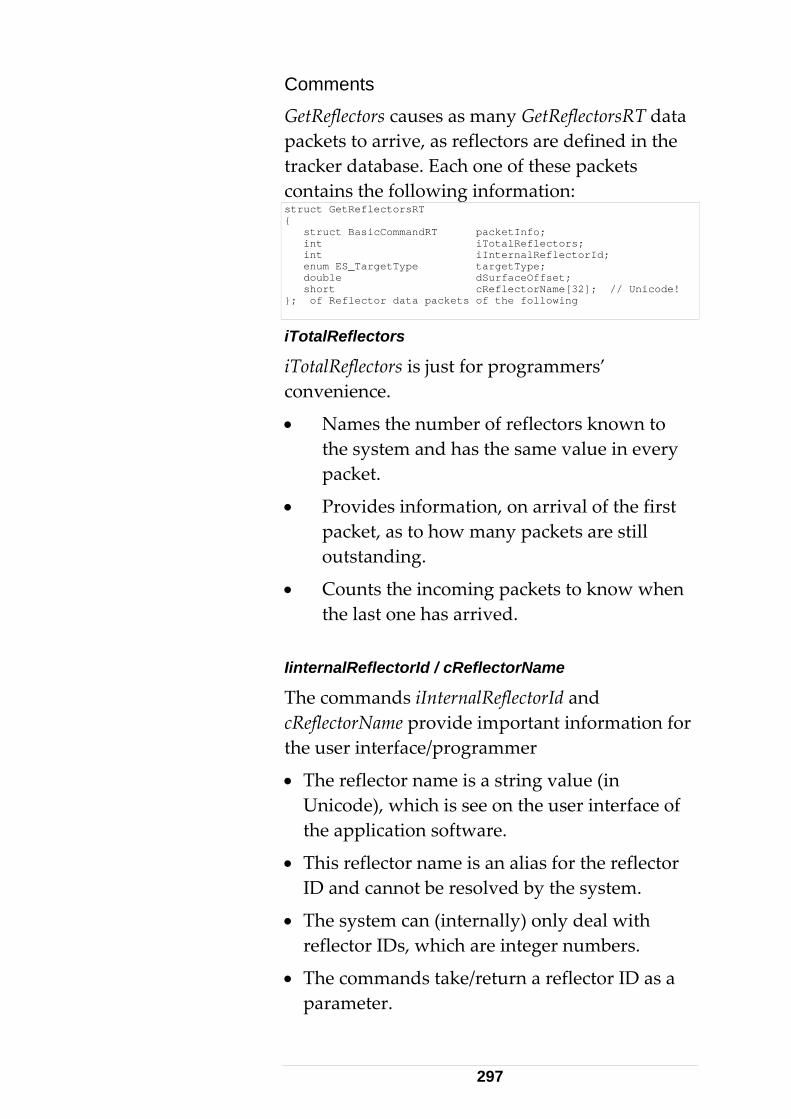
mments tReflectors causes as many GetReflectorsRT
CoGe data packets to arrive, as reflectors are defined in the
a
str
tr cker database. Each one of these packets contains the following information:
uct GetReflectorsRT { struct BasicCommandRT packetInfo; int iTotalReflectors; int iInternalReflectorId; enum ES_TargetType targetType; double dSurfaceOffset; short cReflectorName[32]; // Unicode! }; of Reflector data packets of the following
iTotalReflectors
otalReflectors is just for programmers’ nvenience.
Nam
iTco
• es the number of reflectors known to y
•
• g packets to know when
IinternalReflectorId / cReflectorName
The commands and c ortant information for the user interface/programmer
• tor name is a ing value (in Unicode), which is see on the user interface of
ion software.
ommands take/return a reflector ID as a meter.
the system and has the same value in everpacket.
Provides information, on arrival of the first packet, as to how many packets are still outstanding.
Counts the incominthe last one has arrived.
iInternalReflectorIdReflectorName provide imp
The reflec str
the applicat
• This reflector name is an alias for the reflector ID and cannot be resolved by the system.
• The system can (internally) only deal with reflector IDs, which are integer numbers.
• The cpara
297

• It is crucial to provide the correct reflector ID to SetReflector.
Programmers often fill all reflector names in a list box. When the user selects one of the
, a SetReflector
r quence and may contain
t er
th sequential reflector IDs starting
system behaves differently.
:
m 0 to 2, when the three names are entered in a control list box, in the order shown above. A lookup table is therefore required to match the index values to the reflector IDs. Such a lookup table is shown bIndex ID 0 7
Passing the ID of an unintended (but existing) reflector will cause wrong measurement results.
•
reflectors shown in the list boxcommand is carried out. Hence the need for a 'lookup table'.
List index
• It is not correct to use the index of the list box as a reflector ID. This is because the reflectoIDs are arbitrary in segaps.
• The programmer must not assume that thereflector IDs are a sequence of 1….n withouany gaps. Although most systems may delivreflectors wifrom 0 with no gaps This may not be presumed. Every
• GetReflectors may deliver for example 3 reflectors with the following Names and IDs
Name ID CCR-75mm 7 CCR-1.5in 2 TBR-0.5in 5
Lookup Table
The list box indices will range fro
elow:
298
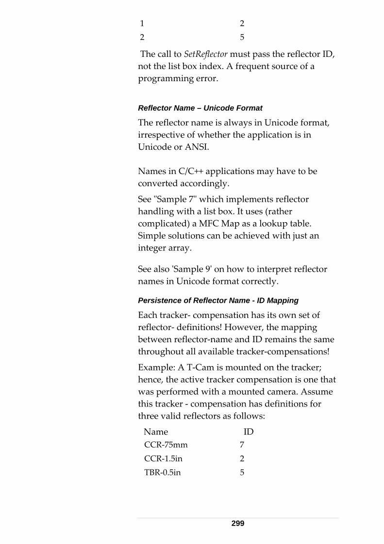
1 2 2 5
The call to SetReflector must pass the reflector ID, not the list box index. A frequent source of a programming error.
Reflector Name – Unicode Format
The reflector name is always in Unicode format, irrespective of whether the application is in Unicode or ANSI.
n
g
tion has its own set of eflector- definitions! However, the mapping
er-compensations!
t ra. Assume
nsation has definitions for
7 2
Names in C/C++ applications may have to be converted accordingly.
See "Sample 7" which implements reflector handling with a list box. It uses (rather complicated) a MFC Map as a lookup table. Simple solutions can be achieved with just ainteger array.
See also 'Sample 9' on how to interpret reflector names in Unicode format correctly.
Persistence of Reflector Name - ID Mappin
Each tracker- compensarbetween reflector-name and ID remains the same throughout all available track
Example: A T-Cam is mounted on the tracker; hence, the active tracker compensation is one thawas performed with a mounted camethis tracker - compethree valid reflectors as follows:
Name ID CCR-75mm CCR-1.5in TBR-0.5in 5
299
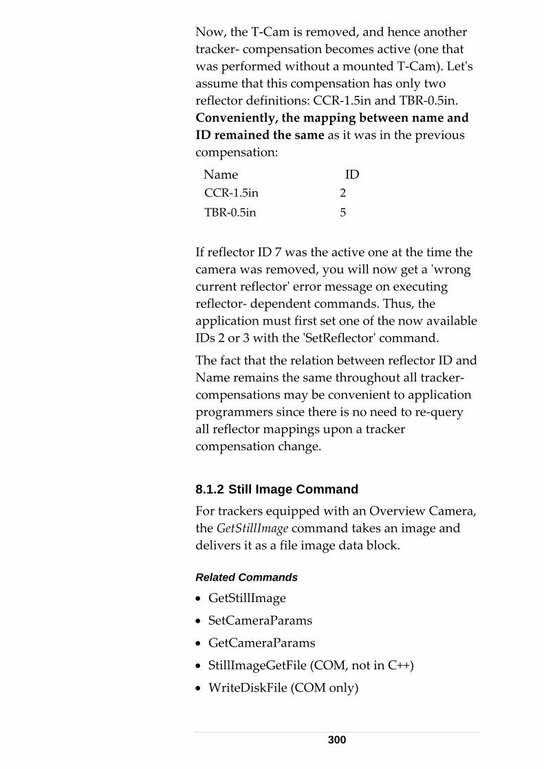
Now, the T-Cam is removed, and hence another tracker- compensation becomes active (one thatwas performed without
a mounted T-Cam). Let's
ssume that this compensation has only two reflector definitions: CCR-1.5in and TBR-0.5in.
the mapping between name and
CCR-1.5in 2 T
reflector ID 7 was the active one at the time the get a 'wrong
ds. Thus, the
relation between reflector ID and acker-
compensations may be convenient to application programmers since there is no need to re-query
8.For trackers equipped with an Overview Camera,
de Related Commands
• GetStillImage
• SetCameraParams
• GetCameraParams
• StillImageGetFile (COM, not in C++)
• WriteDiskFile (COM only)
a
Conveniently,ID remained the same as it was in the previous compensation:
Name ID
BR-0.5in 5
Ifcamera was removed, you will nowcurrent reflector' error message on executing reflector- dependent commanapplication must first set one of the now availableIDs 2 or 3 with the 'SetReflector' command.
The fact that theName remains the same throughout all tr
all reflector mappings upon a tracker compensation change.
1.2 Still Image Command
the GetStillImage command takes an image and livers it as a file image data block.
300

These commands are available on all TPI levels s is not
have to be fulfilled:
“Has video” flag activated
Ap
The application of GetStillImage is explained below using code fragments.
ESsu
The answer to a successfully executed n a
G
• At(f(
The following code accesses the core file data a
C, C++, COM). Set/GetCameraParameter(explained here further.
Preconditions The following preconditions
• Camera mounted on tracker
• System settings:
• Tracker must be in camera view (command ActivateCameraView)
plication of GetStillImage – C/C++
GetStillImage must be called with the parameter _SI_Bitmap. The parameter ES_SI_Jpeg is not pported yet.
•GetStillImage command results i
etStillImageRT data structure.
part from the common header information, his structure echoes the file type imageFiletype =ES_SI_Bitmap), the size of the ile (lFileSize), and the first Byte of the file cFileStart).
• nd writes it to a physical disk file:
301

// assume pData contains the data- block received // to a GetStillImage(ES_SI_Bitmap) command long lFileSize = ((GetStillImageRT*)pData)->lFileSize; char cFileStart = ((GetStillImageRT*)pData)->cFileStart; FILE *pFile = NULL; if ((pFile = fopen("C:\\Temp\\img.bmp", "wb" )) != NULL ) { long lWritten = fwrite(&cFileStart, 1, lFileSize, pFile); if (lWritten != lFileSize) printf("File could not be written(\n"); else printf("wrote %d bytes\n", lWritten); fclose(pFile); }
• The disk- file can be skipped and a memory-mapped file can be used instead. OR
tmap file, the ation can be extracted from the
and used directly with GDI
ket,
f large file data.
(~70 KB), it le
the data packet is complete.
chieve this is shown in the
ee chapter 'Sample9' and chapter 'Queued
COM TPI within C/C++
When using the COM TPI (within a C/C++ application), the results of the LTControl's
• With the file structure of the Bibitmap informdata blockfunctions.
• In the code above, it was assumed that pData ained a complete GetStillImageRT structure cont
with complete file data padded.
WinSock2 API / MFC CAsyncSocket
• Using WinSock2 API or MFC CAsyncSocto read directly from the socket, must considerthe implications o
• Since the file data is relatively big is very unlikely that it will arrive as one singdata block over TCP/IP.
• Provisions must be made to repeat reading data until
• A technique to aOnMessageReceived code sample Sand Scattered Data'.
302

GetStillImage (synchronous) function can be
ing StillImage data sly (Event Handler,
), the difference is that the data ctly through a
er of the fileData.
etStillImage – Synchronous Dlg::OnButtonStillImage()
assumed to be complete. See related code extract below. When receivasynchronouMessageHandlerwill not be provided direparameter. So ILTConnect::GetData() must be used first.
Note the Variant- type paramet
Gvoid CCPPClient{ HRESULT hr = 0; long lFileSize; VARIANT vt; VariantInit(&vt); try { if ((hr = m_pLTCommandSync->GetStillImage(ES_SI_Bitmap, &lFileSize, &vt)) == S_OK) { ASSERT(vt.parray->rgsabound[0].cElements == (unsigned long)lFileSize); FILE *pFile = NULL; // write file to current runtime location if ((pFile = fopen("image.bmp", "wb")) != NULL ) { long lWritten = fwrite(vt.parray->pvData, 1, lFileSize, pFile); if (lWritten != lFileSize) AfxMessageBox(_T("File could not be written\n")); fclose(pFile); // Display the image using MSPaint, // but first close previous instance // HWND hWnd = ::FindWindow(_T("MSPaintApp"), NULL); if (hWnd) // paint is already running - close first ::SendMessage(hWnd, WM_SYSCOMMAND, SC_CLOSE, 0); WinExec("mspaint.exe image.bmp", SW_SHOWNOACTIVATE); } // if } // if } catch(_com_error &e) { Beep(4000, 100); AfxMessageBox((LPCTSTR)e.Description()); } VariantClear(&vt); // Avoid memory leak }
303
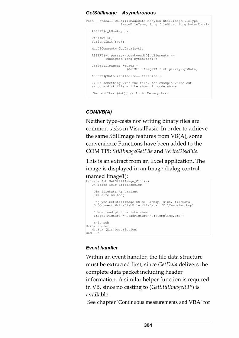
GetStillImage – Asynchr
onous void __stdcall OnStillImageDataReady(ES_StillImageFileType imageFileType, long fileSize, long bytesTotal) { ASSERT(m_bUseAsync); VARIANT vt; VariantInit(&vt); m_pLTConnect->GetData(&vt); ASSERT(vt.parray->rgsabound[0].cElements == (unsigned long)bytesTotal); GetStillImageRT *pData = (GetStillImageRT *)vt.parray->pvData; ASSERT(pData->lFileSize== fileSize); // Do something with the file, for example write out // to a disk file – like shown in code above VariantClear(&vt); // Avoid Memory leak }
COM/VB(A)
xcel application. The
k()
Neither type-casts nor writing binary files are common tasks in VisualBasic. In order to achieve the same StillImage features from VB(A), some convenience Functions have been added to theCOM TPI: StillImageGetFile and WriteDiskFile.
This is an extract from an Eimage is displayed in an Image dialog control
Image1): (namedPrivate Sub GetStillImage_Clic On Error GoTo ErrorHandler Dim fileData As Variant Dim size As Long ObjSync.GetStillImage ES_SI_Bitmap, size, fileData ObjConnect.WriteDiskFile fileData, "C:\Temp\img.bmp" ' Now load picture into sheet Image1.Picture = LoadPicture("C:\Temp\img.bmp") Exit Sub ErrorHandler: MsgBox (Err.Description) End Sub
Event handler
Within an event handler, the file data must be extracted first, since Ge
structure tData delivers the
omplete data packet including header
(GetStillImageRT*) is
VBA' for
cinformation. A similar helper function is required in VB, since no casting toavailable. See chapter 'Continuous measurements and
304

similar method using ContinuousDataGetHeaderInfo.
s Private Sub ObjAsync_StillImageDataReady(ByVal imageFileType ALTCONTROLLib.ES_StillImageFileType, ByVal fileSize As Long, ByVal bytesTotal As Long) Dim fsize as Long ‘dummy ObjConnect.GetData data 'Get whole packet (incl header) ' retrieve out size and file data ObjConnect.StillImageGetFile data, fsize, file ObjConnect.WriteDiskFile file, "img.bmp" ' Now load picture into sheet Image1.Picture = LoadPicture("img.bmp") End Sub
Although designed for use with VB, StillImageGetFile and WriteDiskFile can also be
sed in LTControl based C++ applications.
e currently written
l
ivate Sub Image1_MouseDown(ByVal Button As Integer, ByVal
u
Image Click Position
Click positions on the Image arout to Excel cells. These values can be used to calculate relative tracker movement angles, calMoveRelativeHV to direct the tracker there and then request a new Image. PrShift As Integer, ByVal X As Single, ByVal Y As Single) Beep ws.Cells(2, 2).Value = X ws.Cells(3, 2).Value = Y ws.Cells(5, 2).Value = Shift End Sub
8.1.3 Live Image display
n be implemented into user
Live Image Control LTVideo2.ocx
The live camera display from the Overview Camera caapplications by using an ActiveX control, LTVideo2.ocx. See SDK lib directory, ANSI/Unicode subdirectories.
Registering LTVideo2.ocx
LTVideo2.ocx is an ActiveX type COM object and requires registration on the Application Processor.
305
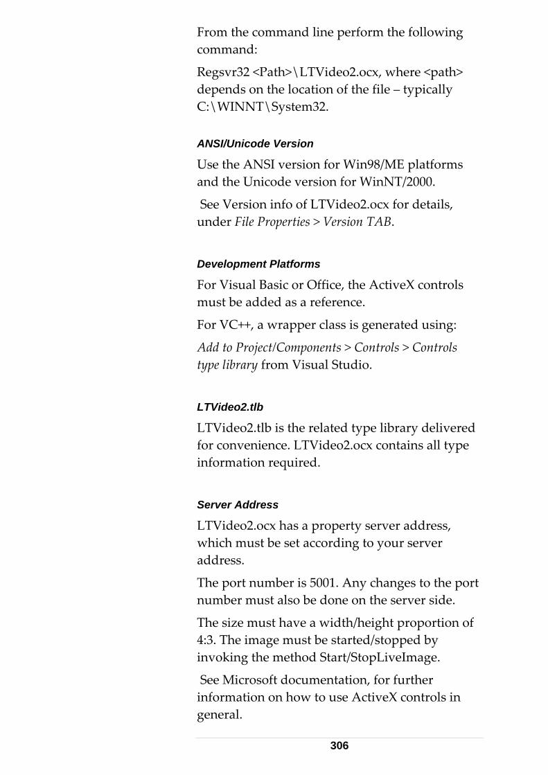
From the command line perform the following
depends on the location of the file – typically C:\WINNT\System32.
98/ME platforms and the Unicode version for WinNT/2000.
See Version info of LTVideo2.ocx for details,
D
For Visual Basic or Office, the ActiveX controls
is generated using:
ts > Controls > Controls
LTVideo2.tlb
LTVideo2.tlb is the related type library delivered finformation required.
S
L idwa
The port number is 5001. Any changes to the port number must also be done on the server side.
The size must have a width/height proportion of 4 Tinvoking the method Start/StopLiveImage.
Minformation on how to use ActiveX controls in general.
command:
Regsvr32 <Path>\LTVideo2.ocx, where <path>
ANSI/Unicode Version
Use the ANSI version for Win
under File Properties > Version TAB.
evelopment Platforms
must be added as a reference.
For VC++, a wrapper class
Add to Project/Componentype library from Visual Studio.
or convenience. LTVideo2.ocx contains all type
erver Address
TV eo2.ocx has a property server address, hich must be set according to your server
ddress.
:3. he image must be started/stopped by
See icrosoft documentation, for further
306
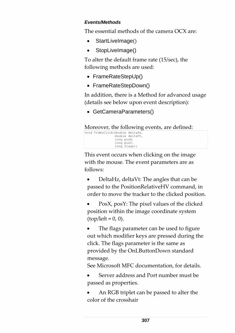
Events/Methods
The essential methods of the ca
• StartLiveImage()
mera OCX are:
nt description):
• StopLiveImage() To alter the default frame rate (15/sec), the following methods are used:
• FrameRateStepUp() • FrameRateStepDown()
In addition, there is a Method for advanced usage (details see below upon eve
• GetCameraParameters()
Moreover, the following events, are defined: void VideoClick(double deltaHz, double deltaVt, long posX, long posY, long flags);
This event occurs when clicking on the image with the mouse. The event parameters afollows:
• DeltaHz, deltaVt: The angles that can be passed to the Poorder to move the tracker to the clicked pos
• PosX, posY: The pixel values of the clickedposition within the image coordinate syst(top/left
• The flags parameter can be used to figuout which modifier keys are pressed during the click. The flags parameter is the same as provided by the OnLButtonDown standard message. See Microsoft MFC documentation, for details.
• Server address and Port number must be
re as
sitionRelativeHV command, in ition.
em
= 0, 0).
re
passed as properties.
• An RGB triplet can be passed to alter the color of the crosshair
307
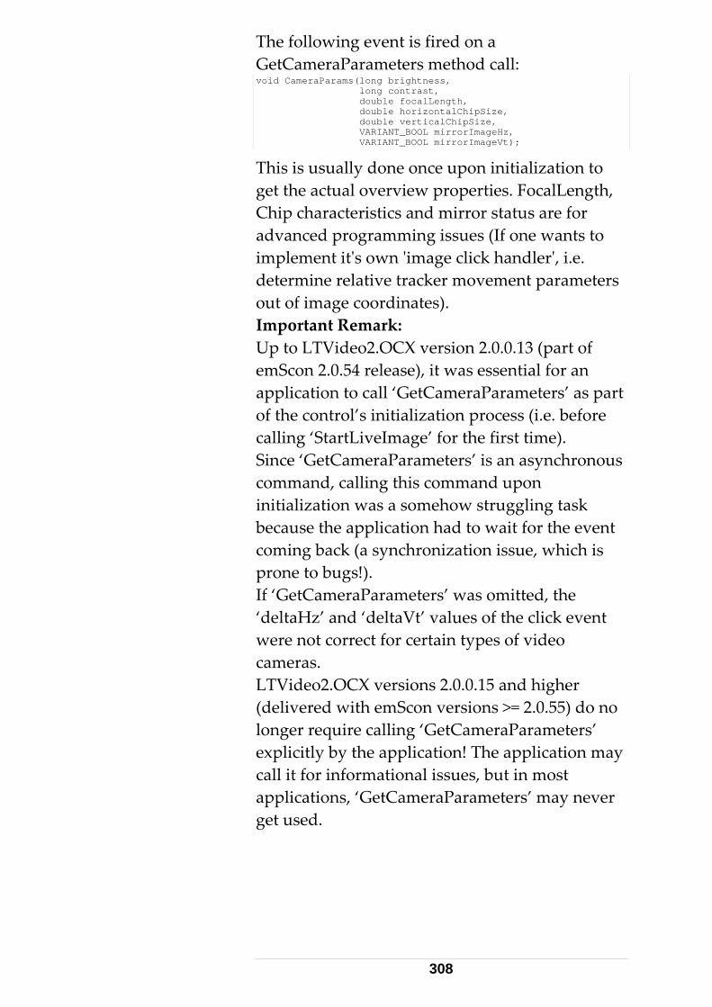
The following event is fired on a GetCameraParameters method call: void CameraParams(long brightness, long contrast, double focalLength, double horizontalChipSize, double verticalChipSize, VARIANT_BOOL mirrorImageHz, VARIANT_BOOL mirrorImageVt);
This is usually done once upon initialization to ,
wn 'image click handler', i.e.
s part f the control’s initialization process (i.e. before
rtLiveImage’ for the first time). ous
prone to bugs!).
ent
ers’ n may
get the actual overview properties. FocalLengthChip characteristics and mirror status are for advanced programming issues (If one wants to implement it's odetermine relative tracker movement parametersout of image coordinates). Important Remark: Up to LTVideo2.OCX version 2.0.0.13 (part of emScon 2.0.54 release), it was essential for an application to call ‘GetCameraParameters’ aocalling ‘StaSince ‘GetCameraParameters’ is an asynchroncommand, calling this command upon initialization was a somehow struggling task because the application had to wait for the event coming back (a synchronization issue, which is
If ‘GetCameraParameters’ was omitted, the ‘deltaHz’ and ‘deltaVt’ values of the click evwere not correct for certain types of video cameras. LTVideo2.OCX versions 2.0.0.15 and higher (delivered with emScon versions >= 2.0.55) do no longer require calling ‘GetCameraParametexplicitly by the application! The applicatiocall it for informational issues, but in most applications, ‘GetCameraParameters’ may neverget used.
308

Sample 18
This Visual Basic sample demonstrates how to
omponent.
of the emScon DK) must be registered first.
is ported to VBA
xcel, or any other MS Office application with BA support).
ty of
The cFurthfolder and code- comments in source files. Sam
Thisimplement a Live Video image without using the 'LTVIt is not recommended to use this approach for Windows- platform targeted applications.
of the
lication
this sample, the application directly connects
mm text :
implement a Live Video image based on the 'LTVideo2.ocx' ActiveX c
Note that 'LTVideo2.ocx' (part S
If no Visual Basic development environment available, the code can easily be(EVSample 18 demonstrates the full functionalithe control, including GetCameraParametersevents and 'Click- handler'.
ode is simple enough to be self- explaining. er details see 'Readme.txt' file in Sample18
ple 19
C++ (MFC) sample demonstrates how to
ideo2.ocx'.
For Windows based applications, we highly recommend rather to use the 'ready to use' LTVideo2.ocx control for implementation of emScon LiveVideo. LTVideo2.ocx is part SDK and its usage is demonstrated in Sample 18.
However, the current LiveVideo CPP appmight be useful for non- Windows based applications (e.g. Linux) since support for LTVideo2.ocx will not be available there.
Into the Video Port (# 5001) of the emScon server. The co and interface is based on Ansitokens. The following commands are supported "LiveImageStart"
309

"LiveImageStop"
"FrameRateStepUp"
"FrameRateStepDown"
"RequestCameraParameters"
s can be sent directly to an open s ke
A iv
- Live Image Data Blocks (Bitmap format)
ks
- CamResult of a 'RequestCameraParameters' call. See source code, function OnReceive(), on hSee source code, function OnPaint(), on how t
The sshoulmentioned, using the LiveVideo TCP/IP interface directly, as shown in this sample only is recommended for non Windows client platforms. Rather base clients on 'LTVideo2.ocx' for
w . 9
ents in source files.
rient
These tokenoc t connection to port 5001.
rr al Data includes the following types:
Note that each image arrives in two chunand must be composed to a complete image before displaying it.
era Parameter Block
ow to parse incoming data.
o display image data.
ource code is commented in detail and d be self- explaining. However, as already
Windo s platform targeted applicationFurther details see 'Readme.txt' file in Sample1folder and code- comm
8.1.4 Orient To Gravity Procedure This function is used to measure the tilt of the tracker's primary z-axis (standing axis) with respect to the vertical. This can be used to o
310
the measurement network to gravity. The tilt is specified by two angulatr
r components about the acker's internal x and y-axes.
C
C
ination
the tracker
rement samples.
2. In addition, the station inclination eters Ix and Iy are calculated and
es not ientation values to
x and Iy, must be explicitly set with the command
nParams (Rotation angles
Tr Thto a given set of nominal points by using a least
wapplied to the measured points in order to
Related Command
• allOrientToGravity
omments • This command is only available in
combination with a Nivel20 InclSensor.
• Executing this command drives head to 4 different positions on the xy plane:
1. Taking Nivel20 measu
paramreturned as result parameters.
• Executing this command do'implicitly' apply any orthe system.
• In order to 'activate' the station orientation to gravity, the two result values, I
SetStationOrientatiorot1 and rot2). See Section 9.2 for mathematical description.
8.1.5 Transformation Procedure See Section 9.2 for a detailed discussion of the
ansformation issue.
is procedure matches a measured set of points
squares, best fit method. The procedure calculates the 7 parameters (x,y,z, omega, phi, kappa, scale),
hich describe the 'transformation filter' to be
311

represent these in the coordinate system defined by Re
•
•
• AddTransformationNominalPoint
• GetTransformedPoints
a
ormationParams
ists, m st be prepared. They must
contain the same number of elements.
using the SetTransformationInputParams command (For example to fix certain parameters. By default,
nInputParams,
ts
the nominal points.
lated Commands
ClearTransformationNominalPointList
ClearTransformationActualPointList
• AddTransformationActualPoint
• SetTransformationInputParams
• GetTransformationInputParams
• CallTransformation
Comments The command CallTransformation displaystransformation carried out with Set/GetTransf
Before doing a CallTransformation, both point lno inal and actual mu
EmScon System Settings
The system settings of emScon (units, coordinate type and coordinate system) must reflect the current input data. Point input values (nominal/actual) are interpreted by emScon based on the current emScon system settings.
• Additional parameters can be set by
i.e if no call to SetTransformatioall parameters are assumed as unknown).
• After a successful calculation, additional resulin terms of transformed points and residuals can be retrieved optionally by using
312

GetTransformedPoints. e of the 7 calculated transformation
scription.
8.1.6 Automated Intermediate Compensation The Intermediate Compensation is a simple and fast procedure to perform a fully automated intermediate compensation, where the tracker is in a fixed installation.
parameters:
ee o-face
tion. It is a simpler and faster a Full Compensation.
ensations do not replace Full
full
Nonparameters (received as output from CallTransformation) are automatically applied tothe system. This must be done explicitly bycalling SetTransformationParams. See Section 9.2 for mathematical de
Tracker Geometry
Out of a total of 15 parameters, which affect the trueness of the tracker geometry, the most significant changes are affected by these three
See emScon manuals, for more information.
• Transit axis tilt, i
• Mirror tilt, c
• Vertical index error, j
Intermediate Compensation refreshes these thrparameters by taking a small number of Twmeasurements. If the result is accepted, it updates only these three parameters and takes over the rest of the overall 15 parameters from the last Full Compensaprocedure than
Intermediate vs. Full Compensation
Intermediate CompCompensations. Regular intermediate compensations extend the interval at whichcompensations need to be carried out.
313

Setup
A network of fixed targets. Based on a given drive libpoints automatically and calculates the Int m
recommended setup is shown below with a
rary the laser tracker measures the target
er ediate Compensation results.
The automated Intermediate Compensatroutine requires that all target locations awith reflectors (recommended 0.5” Tooling Ball or Corner Cube), before the routine is start
ion re fitted
ed.
Are R
Make sure that no one walks around the area duVibrawalking through the beam causes the signal to break. If a measurement fails, the system
ts the measurement to h surement, a maximum of
eediate Compensation can
only be started when the Leica Tracker system is asure.
itial setup it is required that the
a equired
ring the whole Compensation procedure. tion can affect the measurement and
automatically repeaac ieve a successful meathree times. Procedure
R quirements The automated Interm
ready to me
For the inlocations of the fixed targets are measured manually. These locations provide the information for the driver points.
314
• Six Two Face measurements, in two groups of 3 each.
• Each group of 3 points is in an appvertical lin
roximate e.
have a horizontal angle all
measurements reduce the influence of errors. In addition, unstable conditions, such as vibrations and rapid temperature changes, make it necessary for more measurements to be taken. The following combinations are examples:
• Eight measurements in 4 pairs (high and low) separated by approx. 90 degrees.
• Twelve measurements in 4 groups of 3 each (high, low, horizontal), separated by approx. 90 degrees.
Related Commands
- ClearDrivePointList
- AddDrivePoint
- CallIntermediateCompensation
- SetCompensation
Comments
Settings Current emScon system settings, such as units, coordinate system and coordinate type, are taken over when emScon interprets point input (driver
• Minimum distance from the tracker is 2m.
• The high and low measurements should bemore than 30 degrees from the horizontal.
• The groups shouldseparation of about 180 degrees, i.e.measurements should lie approximately in the same vertical plane.
Minimum Measurements
A minimum of 4 measurements is required (mathematically). More
315

point) values. All points in the drive library must ce,
me u
The settings, such as units, coordinate system and coordinate system type, must correspond to the input data. Ensure that the settings describe the environment of the driver points before they are uploaded to the server.
f the automated
s
otherwise it will abort.
be known within ± 2mm (0.0787 in) toleranotherwise this will cause an error in the
as rements.
One of the first actions ocompensation algorithm is to check the geometryof the used driver points. If the target setup fitthe requirements (as described above), then theprocess continues with the measurements,
316

Compensation Results A successful Intermediate Compensation procedure returns the following information:
• Total RMS
• Max. Deviation
ended hen the maximum deviation is ≤ 0.0012 deg
cc SetCompensation the sation can be activated.
o Face Field-Check
predefined parameters. It does not, however, rrections.
Periodi
If the tconduct the field check on a weekly basis. If the field check results show no change, over a period of six weeks, carry out field checks at least once a month.
If the tracker has been moved, always carry out a field check before taking measurements.
Compensations and field checks must be carried out in normal working conditions, under which
Field che asurement
Two fpositions, distributed over the whole object
• Error bit filed with the information of warnings and errors.
Compensation Intervals An intermediate compensation is recommw(13 ). With the command new calculated compen 8.1.7 TwA field check is a control process of the Compensation parameters. It checks the condition of the Leica Tracker, with respect to
provide for compensatory co
city
racker is used in a stationary position,
the measurements are taken.
ck two face Me
ace measurements with 4 to 5 reflector
317

range
ments must be within the specification.
Client Routine
The Tracker Server Programming Interface does not have a specific two face measurement mode. A client routine is required, which can use the basic functionality provided.
See chapter 'Procedure – Measurement'.
Pro
The procedure requires the following three
2 One measurement set on a vertical line.
3 One measurement plus or minus 90° to the vertical line.
Measurements on a Straight Line
1. The two measurements must be taken on a straight line (ray) at the same level as the as the Tilting mirror of the Tracker. Point A <0.5 m and Point B within 5-l0 m.
1.
Measurements on a Vertical Line
.
2. Upper measurement at +40° deg.
, will indicate whether the Tracker compensation is within specifications. To achievea 2-sigma accuracy, 95 % of the measure
cedure - Preparation
setups:
1 Two measurements on a straight line.
A B <0.5 m >5-10 m
2. All 3 measurements should be taken in avertical line
1. Mid point 0° at Tracker head height.
318

3. Lower measurement at -40° deg.
During measurements, the Birdbath should not point in the direction of measurement.
Measurement ± 90° to the Vertical Line.
3. Setup thegraphic below.
tripod at 90°, as shown in the
90
The Tracker is setup such that it can turn to the ° position, without running into stop.
319

Procedure - Measurement
oordinate system type to spherical
command: SetCoordinateSystemType.
ode. e
TPI command: SetStationaryModeParams
5. Attach the reflector to the target location.
6. Point the tracker to the target location. TPI command: e.g. GoPostion. This is only possible when the coordinates of the point are known within ± 2mm, otherwise track the reflector manually from the Bird bath.
7. Execute the Stationary Measurement in Face I and save it. TPI command: StartMeasurement
8. Execute the command Change Face, which puts the Laser Tracker from Face I to Face II. The pointing to a fixed reflector position from a station should be the same in both faces. TPI command: ChangeFace
9. Execute the Stationary Measurement in Face II and save it. TPI command: StartMeasurement.
10. Execute the command Change face, which puts the Laser Tracker from Face II to Face I. TPI command: ChangeFace.
11. Repeat the steps 5 - 10 for all target locations.
Procedure - Calculation
Devvt = vertical angle Face I – vertical angle Face II
1. Set up the tracker.
2. Set the cclock wise, SCW, TPI
3. Set the Stationary Measurement MTPI command: SetMeasurementMod
4. Set the Stationary measurement parameter. MeasTime to 10000ms
320
D ori ngle Fa
Both measurements are in Face I representation. Face II measurements are represented in Face I.
are:
ertical angle = ±13cc (0.0012 De )
Horizontal angle = ±13cc (0.0012 Deg)
te
evh = h zontal angle Face I – horizontal ace II
Example
Devvt = 90.7289893– 90.7287338 = 0.0003 Deg Devh = 269.9877001– 269.9879985 = -0.0003 Deg Tolerances
The recommended tolerances of the deviations
V g
When the tolerance is exceeded, an IntermediaCompensation is recommended.
321

9 Mathematics
9.1 Point accuracy Throughout Emscon point coordinate
ce matrix. It is a matrix with the squares of the
respective standard deviations on the diagonal:
s are stored together with a 3x3 covariansymmetric 3x3
21 12 13
212 2 23
1
stdDev covar covarcovar stdDev covarcovar
⎛ ⎞⎜ ⎟⎜ ⎟⎜⎝
2
3 23 3covar stdDev ⎟⎠
s defined by the ce
The error ellipsoid of the point ieigenvectors and eigenvalues of the covarianmatrix. If the covariance matrix is diagonal, the axes of the error ellipsoid are parallel to the coordinate axes. The correlations
*ij
iji j
covarstdDev stdDev
ρ =
satisfy the relations 1 1ijρ− ≤ ≤ .
At the TPI point coordinates together with the covariance matrix are passed in the fonon-redundant form:
llowing
.
Coord1, Coord2, Coord3, StdDev1, StdDev2, StdDev3, Covar12, Covar13, Covar23
9.1.1 A priori accuracy For continuous measurements, the a priori covariance matrix of a point measurement is calculated according to the tracker accuracy. Emscon adapts the following model:
max(1.25E-5/d, 5E-6)StdDevH =
2
max(1.25E-5/d, 5E-6)
1E-10 + (1.25E-6 d)
StdDevV
StdDevD
=
= ⋅
322

where d denotes the measured distance in metersH and V denotes the horizontal and verticain radians. This formula applies in the case of
. l angle
ond
IFM measurements initialized at bird bathdistance. The angle accuracy is constant bey2.5m and slightly poorer at close range. Simplified homogeneous models are
max(10E-6 d, 25 )StdDevXYZ µ= ⋅ or even simpler 50StdDevXYZ µ= . The a priori accuracy inc
unresolved systematic errors and indicates the reliability of a measurement. This kind of
ludes
used as input to any further
It
this
9.1.3 Transformation of covariance matrices In the (spherical) tracker coordinate system the a priori covariance matrix of a tracker measurement is diagonal (see formulas above). Conversion to Cartesian coordinates results in a full matrix. Transformation to other coordinate systems using orientation and/or transformation parameters (Section 9.2 below) again transforms the covariance matrix. However, at any stage the standard deviations, i.e. the square roots of the diagonal entries provide a reasonable estimate on the accuracy of the respective coordinate triple.
accuracy should becalculation. 9.1.2 A posteriori accuracy For single point measurements (stationary, sphere center, circle center) also the a posteriori or repeatability covariance is calculated from the actual statistical variation of the many shots. gives an indication on the stability of the measurement environment disregarding systematic effects. We recommend not usingaccuracy for any other purpose.
9.2 Orientation and TransformationThe orientation takes the instrument coordinate system to the world coordinate system and thtransformation takes the world coordinate system
e
323

to an object coordinate syse
tem. The two are used ither by them selves or together to show
coordinates in the required coordinate system.
See Section 8.1.5 for a survey on the TPI commands used to calculate orientation or transformation parameters. The major input to these calculations are the coordinates of a set of reference points together with the corresponding measured coordinates. The result of the calculation is a seven parameter transformation of the measured points onto the reference points. 9.2.1
refers to the alignment of a tracker oordinate system (WCS).
point
reference
Orientation Orientationwith respect to a world cThe world coordinate system may be defined bythe principal measurement station (Fig. 1) or by a CAD model (Fig. 2). The coordinates of awith respect to the principal station or CAD model respectively are called nominal orcoordinates. The coordinates as measured by the active station are called actual coordinates.
Fig. 1
Setting the calculated parameters as orientation parameters with the SetStationO m
sure re sal coordinates approxi qual to
rientationParams com and and re-meayields actu
ment of the refe nce pointmately e
324
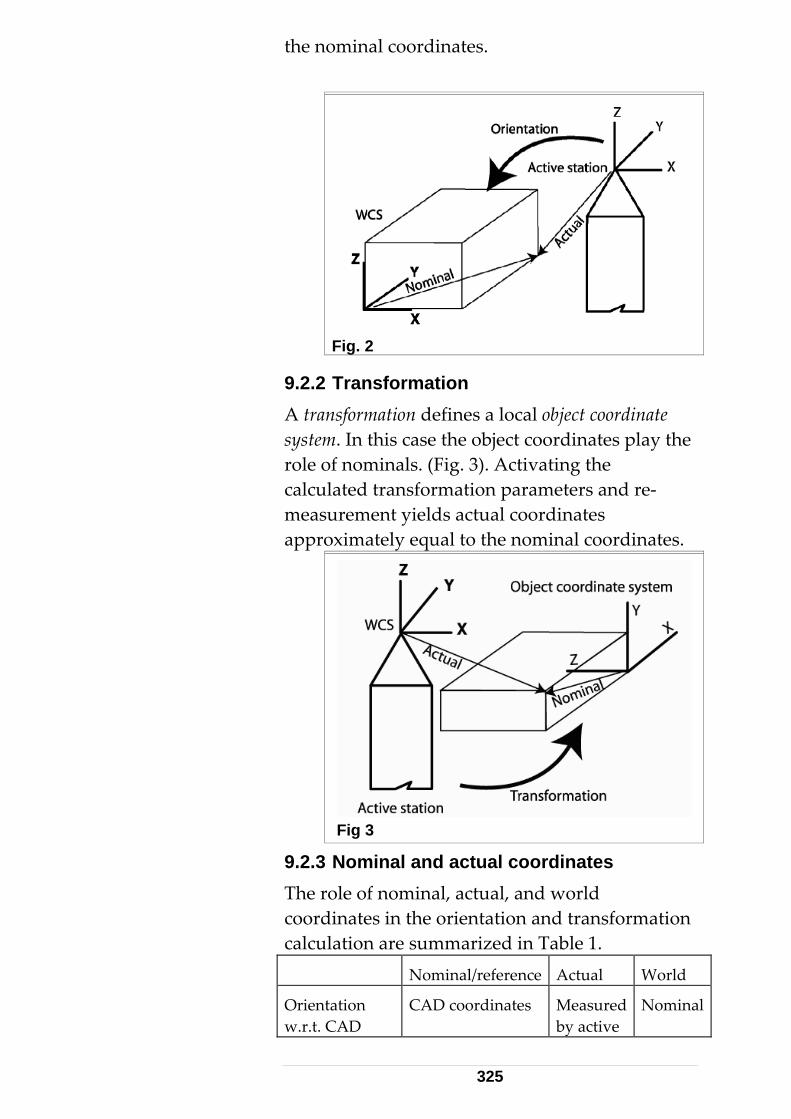
the nominal coordinates.
Fig. 2
9.2.2 Transformation A transformation defines a local object coordinate system. In this case the object coordinates play the role of nominals. (Fig. 3). Activating the calculated transformation parameters and re-measurement yields actual coordinates approximately equal to the nominal coordinate
s.
Fig 3
9.2.3 Nominal and actual coordinates The role of nominal, actual, and world coordinates in the orientation and transformation alculation are summarized in Table 1.
Nominal/reference Actual World
c
Orientation w.r.t. CAD
CAD coordinates Measured by active
Nominal
325

station
Orientation w.r.t. 1st station
Measured by 1st station
Measured by active
ion
Nominal
stat
Transformation Object coordinates Measured by active station
Actual
Table 1
ion are both seven
ence
orresponding reference points in a to
hen describing a temperature orientation case the
9.2.4 Orientation parameters Orientation and transformatparameter transformations consisting of three translation, three rotation, and one scale parameter. They describe a mapping of a given set of actual points onto a given set of referpoints. The mapping is calculated such as tominimize the deviation between the transformed points and the cleast squares sense. Typically the scale is close one, e.g. wdependent dilation. In themap assumes the form:
( ) /T x t Rx s= +
with 3D translation t vector
rotaticale
= 3x3
sRs
on matrix==
dinThe correspon
g residuals are:
( )residual T actual nominal= −
b or
of R. In terms of the rotation angles le, zAngle the rotation matrix
he form
The map T can e interpreted as a coordinate system with itsthe columnsxAngle, yAng
igin at t and the axes given by
assumes t
cz cy -sz cy sy
sz cx+cz sy sx cz cx-sz sy sx -cy sxsz sx-cz sy cx cz sx+sz sy cx cy cx
R⋅ ⋅⎛ ⎞
⎜ ⎟= ⋅ ⋅ ⋅ ⋅ ⋅ ⋅ ⋅⎜ ⎟⎜ ⎟
⋅ ⋅ ⋅ ⋅ ⋅ ⋅ ⋅⎝ ⎠
where
326
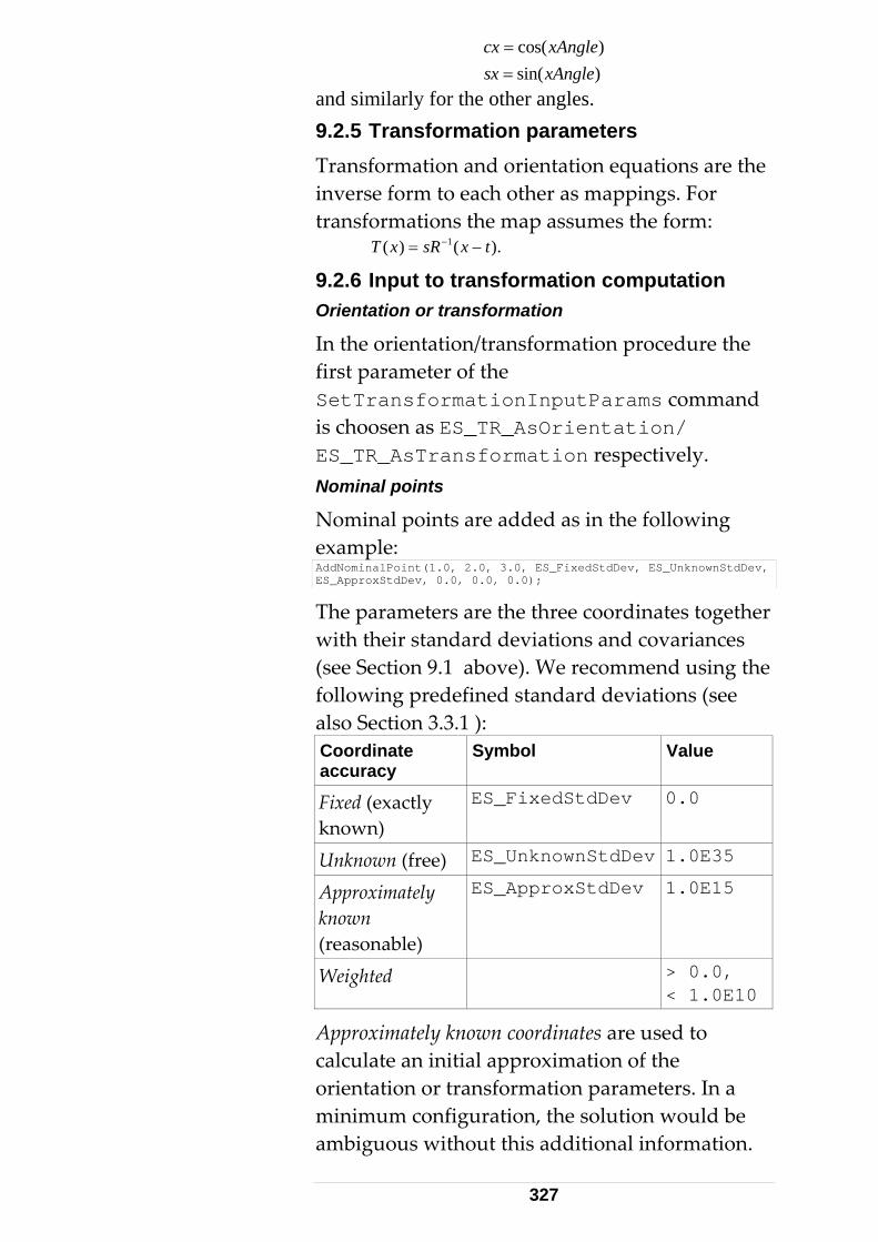
cos( )cx xAngle=
re the
sin( )sx xAngle=and similarly for the other angles. 9.2.5 Transformation parameters Transformation and orientation equations ainverse form to each other as mappings. For transformations the map assumes the form:
1( ) ( ).T x sR x t−= −
9.2.6 Input to transformation computation Orientation or transformation
In the orientation/transformation procedfirst parameter of the SetTransformationInputParams commanis choosen as ES_TR_AsOrientation/ ES_TR_AsTransformation respectively.
ure the
d
v,
Nominal points
Nominal points are added as in the following example: AddNominalPoint(1.0, 2.0, 3.0, ES_FixedStdDev, ES_UnknownStdDeES_ApproxStdDev, 0.0, 0.0, 0.0);
The parameters are the three coordinates together riances
ing the defined standard deviations (see
with their standard deviations and cova(see Section 9.1 above). We recommend usfollowing prealso Section 3.3.1 ): Coordinate accuracy
Symbol Value
Fixed (exactly known)
ES_FixedStdDev 0.0
Unknown (free) ES_UnknownStdDev 1.0E35
Approximately known
ES_ApproxStdDev 1.0E15
(reasonable) Weighted > 0.0,
< 1.0E10
Approximately known coordinates are used to calculate an initial approximation of the orientation or transformation parameters. In a minimum configuration, the solution would be ambiguous without this additional information.
327
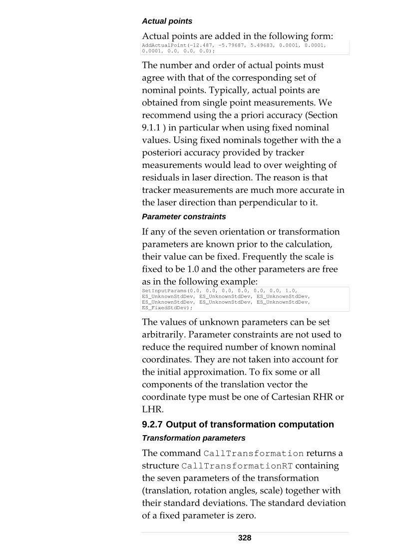
Actual points
Actual points are added in the following form: AddActualPoint(-12.487, -5.79687, 5.49683, 0.0001, 0.0001, 0.0001, 0.0, 0.0, 0.0);
The number and order of actual points must agree with that of the corresponding set of
ominal points. Typically, actual oints are
a
g of
If any of the seven orientation or transformation parameters are known prior to the calculation, their value can be fixed. Frequently the scale is
nd the other parameters are free
1.0,
n pobtained from single point measurements. We recommend using the a priori accuracy (Section9.1.1 ) in particular when using fixed nominal values. Using fixed nominals together with theposteriori accuracy provided by tracker measurements would lead to over weightinresiduals in laser direction. The reason is that tracker measurements are much more accurate in the laser direction than perpendicular to it. Parameter constraints
fixed to be 1.0 aas in the following example: SetInputParams(0.0, 0.0, 0.0, 0.0, 0.0, 0.0,ES_UnknownStdDev, ES_UnknownStdDev, ES_UnknownStdDev, ES_UnknownStdDev, ES_UnknownStdDev, ES_UnknownStdDev, ES_FixedStdDev);
T phe values of unknown arameters can be set arbitrarily. Parameter constraints are not used to
unt for imation. To fix some or all
e oordinate type must be one f Cartesian RHR or
rmation computation
s a
h
of a fixed parameter is zero.
reduce the required number of known nominal coordinates. They are not taken into accothe initial approxcomponents of the translation vector thc oLHR. 9.2.7 Output of transfoTransformation parameters
The command CallTransformation returnstructure CallTransformationRT containingthe seven parameters of the transformation (translation, rotation angles, scale) together wittheir standard deviations. The standard deviation
328

Transformed points and residuals
he command returns ed
T GetTransformedPointa list of structures, each containing a transformpoint together with its covariance matrix and the three coordinates of the residual vector
residual nominal transformed= −
e transformation calculated. he covariance matrix of the residual is obtained by adding those
als
The covariance matrix of the transformed point takes into account the covariance matrix of the actual point and the 7 by 7 covariance matrix of th T
of the nominal and the transformed point. Statistics
The command CallTransformation also returns the
• RMS of residuals
• Maximum deviation
• Variance factor RMS of residu
The RMS of residuals is defined as
2
1i
iresidual
RMSnoEquations
==∑
where the number of equations is the number of fixed or weighted nominal coordinates. Maximum deviation
The maximum deviation is defin
n
ed as
1..i n residual= i
tes
alues of the transformation par eters in the weighted least squares sense. This means that the following target functional is minimized:
maxDev max=
where fixed and weighted nominal coordinaare taken into account. Weighted residual square sum
The transformation algorithm determines the v am
329
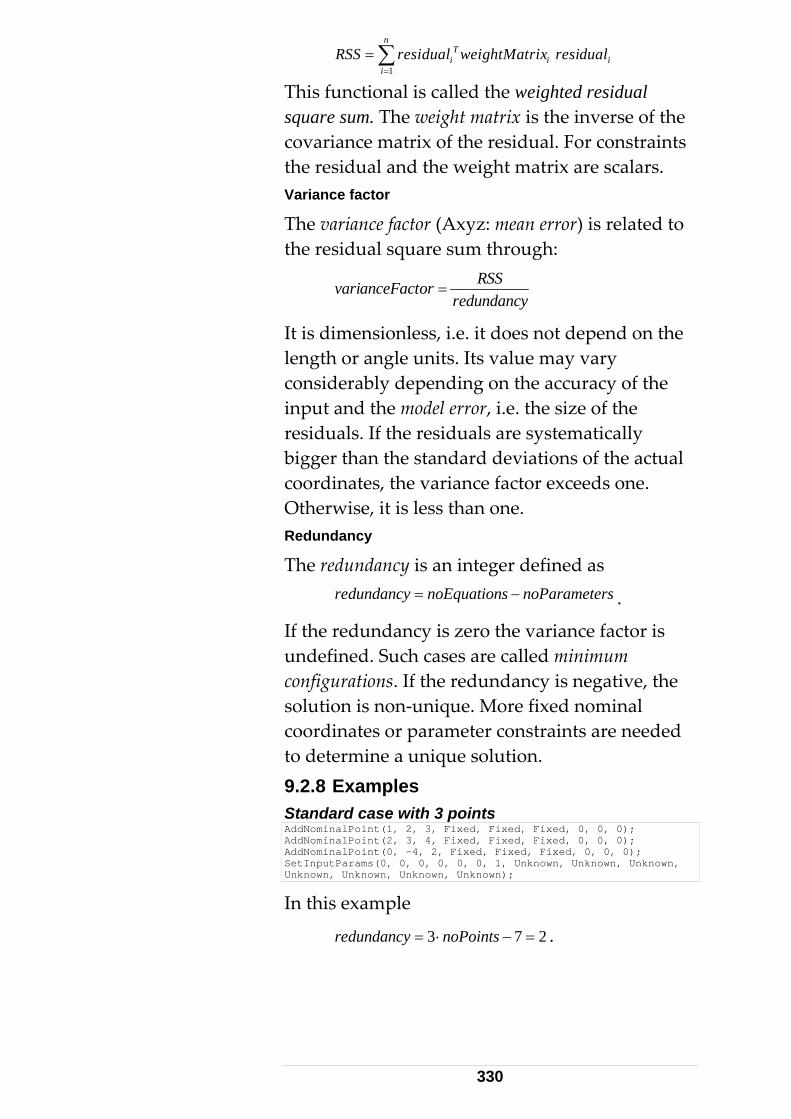
n
1i=
Ti i iRSS residual weightMatrix residual= ∑
This functional is called the weighted residual square sum. The weight matrix is the inverse of the
s covariance matrix of the residual. For constraintthe residual and the weight matrix are scalars. Variance factor
The variance factor (Axyz: mean error) is related to the residual square sum through:
RSSvarianceFactor
redundancy=
It is dimensionless, i.e. it does not depend on the ngth or angle units. Its val e may vary
considerably depending on the accuracy of the or, i.e. the size of the
residuals. If the residuals are systematically igger than the standard d viations of the actual
coordinates, the variance factor exceeds one. Otherwise, it is less than one.
ancy
The redundancy is an integer defined as
le u
input and the model err
b e
Redund
redundancy noEquations noParameters= − .
If the redundancy is zero the variance factor is . Such cases are called minimum
ded
undefinedconfigurations. If the redundancy is negative, thesolution is non-unique. More fixed nominal coordinates or parameter constraints are neeto determine a unique solution. 9.2.8 Examples Standard case with 3 points AddNominalPoint(1, 2, 3, Fixed, Fixed, Fixed, 0, 0, 0); AddNominalPoint(2, 3, 4, Fixed, Fixed, Fixed, 0, 0, 0); AddNominalPoint(0, -4, 2, Fixed, Fixed, Fixed, 0, 0, 0); SetInputParams(0, 0, 0, 0, 0, 0, 1, Unknown, Unknown, Unknown, Unknown, Unknown, Unknown, Unknown);
In this example
3 7 2redundancy noPoints= ⋅ − = .
330
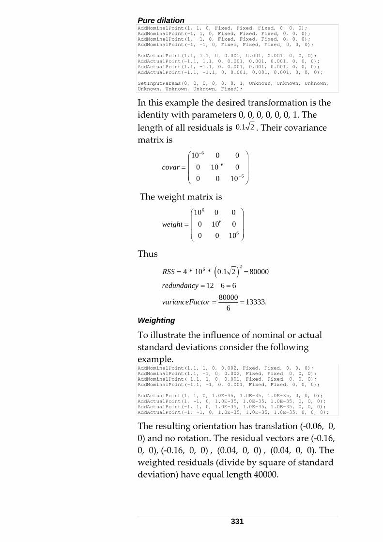
Pure dilation AddNominalPoint(1, 1, 0, Fixed, Fixed, Fixed, 0, 0, 0); AddNominalPoint(-1, 1, 0, Fixed, Fixed, Fixed, 0, 0, 0); AddNominalPoint(1, -1, 0, Fixed, Fixed, Fixed, 0, 0, 0); AddNominalPoint(-1, -1, 0, Fixed, Fixed, Fixed, 0, 0, 0); AddActualPoint(1.1, 1.1, 0, 0.001, 0.001, 0.001, 0, 0, 0); AddActualPoint(-1.1, 1.1, 0, 0.001, 0.001, 0.001, 0, 0, 0); AddActualPoint(1.1, -1.1, 0, 0.001, 0.001, 0.001, 0, 0, 0); AddActualPoint(-1.1, -1.1, 0, 0.001, 0.001, 0.001, 0, 0, 0); Se kntInputParams(0, 0, 0, 0, 0, 0, 1, Un own, Unknown, Unknown, Unknown, Unknown, Unknown, Fixed);
In this example the desired transformation is thidentity with parameters 0, 0, 0, 0, 0, 0, 1. The length of all residuals is
e
0.1 2 . Their covariance matrix is
6−
6
6
0 10 00 0 10
covar −
−
⎜ ⎟= ⎜ ⎟⎜ ⎟⎝ ⎠
10 0 0⎛ ⎞
The weight matrix is
6
6
6
10 0 00 10 00 0 10
weight⎛ ⎞⎜ ⎟= ⎜ ⎟⎜ ⎟⎝ ⎠
Thus
( )264 * 10 * 0.1 2 80000RSS = =
12 6 6redundancy = − = 80000 13333.
6varianceFactor = =
Weighting
To illustrate the influence of nominal or actual standard deviations consider the following example. AddNominalPoint(1.1, 1, 0, 0.002, Fixed, Fixed, 0, 0, 0); AddNominalPoint(1.1, -1, 0, 0.002, Fixed, Fixed, 0, 0, 0); AddNominalPoint(-1.1, 1, 0, 0.001, Fixed, Fixed, 0, 0, 0); AddNominalPoint(-1.1, -1, 0, 0.001, Fixed, Fixed, 0, 0, 0); AddActualPoint(1, 1, 0, 1.0E-35, 1.0E-35, 1.0E-35, 0, 0, 0); AddActualPoint(1, -1, 0, 1.0E-35, 1.0E-35, 1.0E-35, 0, 0, 0); AddActualPoint(-1, 1, 0, 1.0E-35, 1.0E-35, 1.0E-35, 0, 0, 0); AddActualPoint(-1, -1, 0, 1.0E-35, 1.0E-35, 1.0E-35, 0, 0, 0);
The resulting orien0) and no rotation
tation has translation (-0.06, 0, . The residual vectors are (-0.16,
d
0, 0), (-0.16, 0, 0) , (0.04, 0, 0) , (0.04, 0, 0). Theweighted residuals (divide by square of standardeviation) have equal length 40000.
331
3-2-1 Alignment AddNominalPoint(1, 2, 3, Fixed, Fixed, Approx, 0, 0, 0); AddNominalPoint(2, 3, 4, Fixed, Fixed, Fixed, 0, 0, 0); AddNominalPoint(0, -4, 2, Approx, Fixed, Approx, 0, 0, 0); SetInputParams(0, 0, 0, 0, 0, 0, 1, Unknown, Unknown, Unknown, Unknown, Unknown, Unknown, Fixed);
This is a minimum configuration since
2 3 1 6 0.redundancy = + + − =
The approximate coordinates are necessary to select a unique solution from the eight posssolutions. This fact can be
ible easily observed in the
following example: AddNominalPoint(0, 0, 0, Fixed, Fixed, Fixed, 0, 0, 0); AddNominalPoint(1, 0, 0, Unknown, Fixed, Fixed, 0, 0, 0); AddNominalPoint(1, 1, 0, Unknown, Unknown, Fixed, 0, 0, 0);
Here each of the rotation angles can be 0 or π. The scale must be fixed in 3-2-1 situations. Box corner
The corner of a box is defined by three mutually perpendicular planes. In the subsequent example each plane contains two measured points. Only the nominal coordinate defining the plane is exactly known. AddNominalPoint(0, 1, 1, Fixed, Approx, Approx, 0, 0, 0); AddNominalPoint(0, 2, 2, Fixed, Approx, Approx, 0, 0, 0); AddNominalPoint(1, 0, 1, Approx, Fixed, Approx, 0, 0, 0); AddNominalPoint(1, 0, 2, Approx, Fixed, Approx, 0, 0, 0); AddNominalPoint(1, 1, 0, Approx, Approx, Fixed, 0, 0, 0); Ad 0dNominalPoint(2, 2, 0, Approx, Approx, Fixed, 0, , 0);
Again, this is a minimum configuration provided the scale is fixed. Orientation using Nivel measurement
Suppose the horizontal angles xAngle and yAngle have been obtained from a Nivel measurement. To complete the orientation of the station use a number of reference points together with: SetInputParams(0, 0, 0, xAngle, yAngle, 0, 1, Unknown, Unknown, Unknown, Fixed, Fixed, Unknown, Fixed);
9.3 T-Probe The coordinate system of the T-Probe is defined as in Figure 1 with the z-axis pointing roughly towards the camera and the y-axis opposite to mount 1. Thus the y coordinate of a tip vector at mount 1 is negative.
332
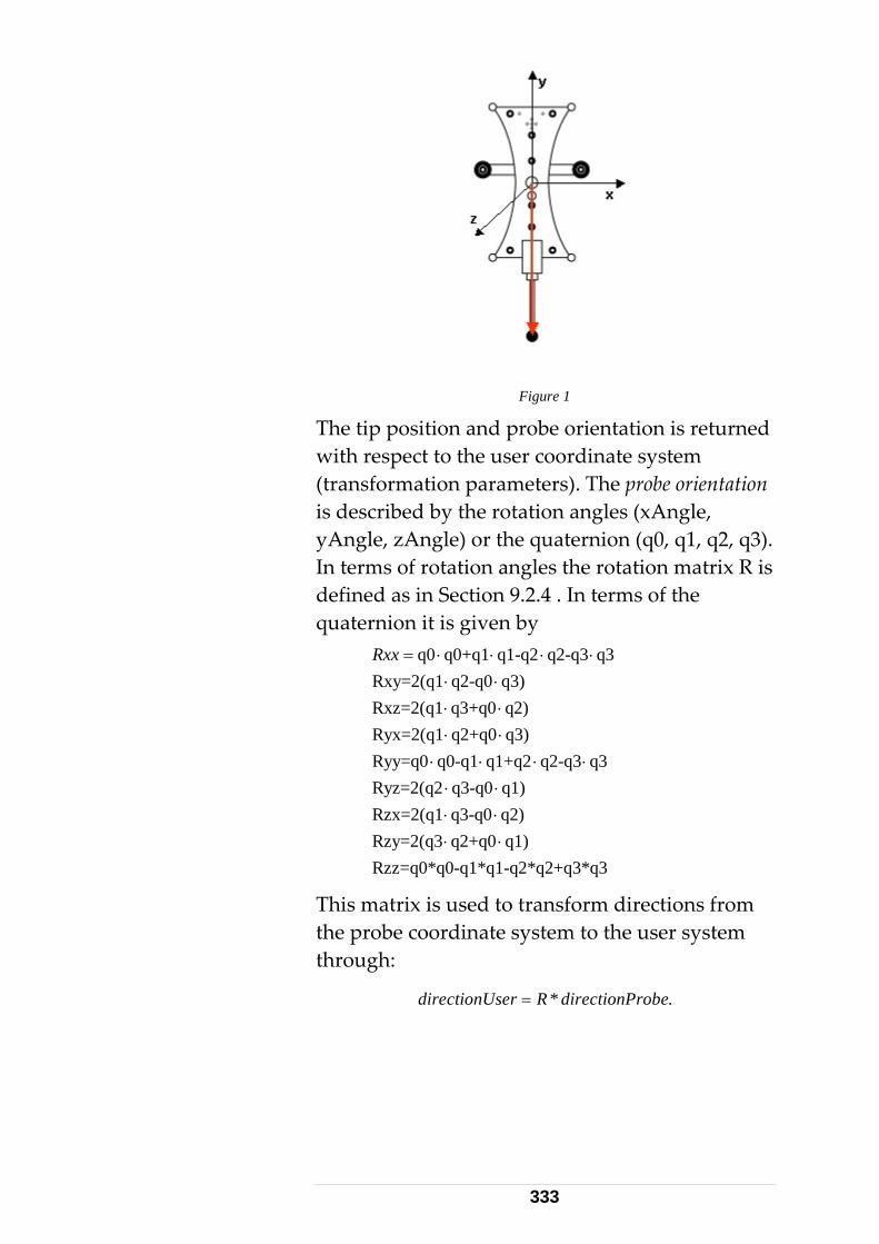
Figure 1
The tip position and probe orientation is returned with respect to the user coordinate system (transformation parameters). The probe orientation is described by the rotation angles (xAngle,
or the quaternion (q0, q1, q2, q3). the rotation matrix R is
.4 . In terms of the
-q0 q3)
q2)
0-q1*q1-q2*q2+q3*q3
yAngle, zAngle)In terms of rotation anglesdefined as in Section 9.2quaternion it is given by
q0Rxx q0+q1 q1-q2 q2-q3 q3Rxy=2(q1 q2Rxz=2(q1 q3+q0 q2)Ryx=2(q1 q2+q0 q3)Ryy=q0 q0-q1 q1+q2 q2-q3 q3Ryz=2(q2 q3-q0 q1)Rzx=2(q1 q3-q0Rzy=2(q3 q2+q0 q1)Rzz=q0*q
= ⋅ ⋅ ⋅ ⋅⋅⋅
⋅ ⋅⋅ ⋅
⋅ ⋅ ⋅ ⋅⋅ ⋅⋅ ⋅⋅ ⋅
ed to transform directions from the user system
nUser R directionProbe
This matrix is usthe probe coordinate system tothrough:
dir * .= ectio
333
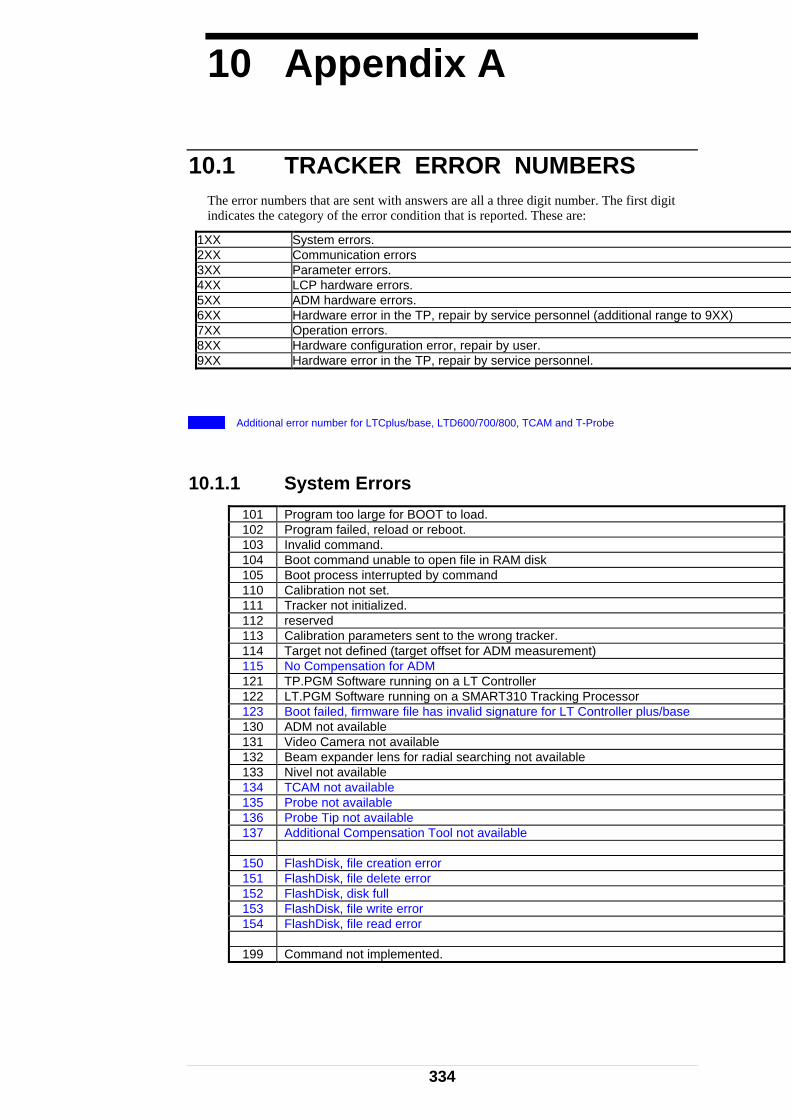
10 Appendix A
10.1 TRACKER ERROR NUMBERS
The error num er. The first digit indica c
1XX
bers that are sent with answers are all a three digit numbat is reported. These are:tes the ategory of the error condition th
System errors. 2XX Communication errors 3XX Parameter errors. 4XX LCP hardware errors. 5XX ADM hardware errors. 6XX y service personnel (additional range to 9XX) Hardware error in the TP, repair b7XX Operation errors. 8XX Hardware configuration error, repair by user. 9XX . Hardware error in the TP, repair by service personnel
Additional error number for LTCplus/base, LTD600/700/800, TCAM and T-Probe
0.1.1 System Errors 1 101 Program too large for BOOT to load. 102 Program failed, reload or reboot. 103 Invalid command. 104 Boot command unable to open file in RAM disk 105 Boot process interrupted by command 110 Calibration not set. 111 Tracker not initialized. 11 reserved 2 113 Calibration parameters sent to the wrong tracker. 114 Target not defined (target offset for ADM measurement) 115 No Compensation for ADM 121 TP.PGM Software running on a LT Controller 122 LT.PGM Software running on a SMART310 Tracking Processor 123 Boot failed, firmware file has invalid signature for LT Controller plus/base 130 ADM not available 131 Video Camera not available 132 Beam expander lens for radial searching not available 133 Nivel not available 13 TCAM not available 4 135 Probe not available 136 Probe Tip not available 137 Additional Compensation Tool not available 150 FlashDisk, file creation error 151 FlashDisk, file delete error 152 FlashDisk, disk full 153 FlashDisk, file write error 154 FlashDisk, file read error 199 Command not implemented.
334
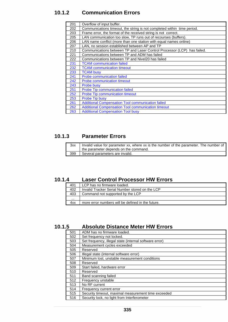
10.1.2 ation Errors
201 verflow of input buffer.
Communic O 202 Communications timeout, the string is not completed within time period. 203 t. Frame error, the format of the received string is not correc 205 AN communication too slow, TP runs out of recourses (buffers). L 206 LAN name conflict (more than one station with equal names online) 207 LAN, no session established between AP and TP 210 Communications between TP and Laser Control Processor (LCP) has failed. 221 Communications between TP and ADM has failed 222 Communications between TP and Nivel20 has failed 231 TCAM communication failed 232 TCAM communication timeout 233 TCAM busy 241 Probe communication failed 242 Probe communication timeout 243 Probe busy 251 Probe Tip communication failed 252 Probe Tip communication timeout 253 Probe Tip busy 261 Additional Compensation Tool communication failed 262 Additional Compensation Tool communication timeout 263 Additional Compensation Tool busy
10.1.3e number of the parameter. The number of
Parameter Errors 3xx Invalid value for parameter xx, where xx is th
the parameter depends on the command. 399 Several parameters are invalid. 10.1.4 sor HW Errors Laser Control Proces 401 LCP has no firmware loaded. 402 Invalid Tracker Serial Number stored on the LCP 403 Command not supported by the LCP ... 4xx more error numbers will be defined in the future.
10.1.5 rrors 501 ADM has no firmware loaded. Absolute Distance Meter HW E
502 Set frequency not locked. 503 Set frequency, illegal state (internal software error) 504 Measurement cycles exceeded 505 Reserved 50 Illegal state (internal software error) 6 507 Minimum lost, unstable measurement conditions 508 Reserved 509 Start failed, hardware error 510 Reserved 511 Band scanning failed 512 Frequency unstable 513 No RF current 514 Frequency current error 515 Security timeout, maximal measurement time exceeded 516 Security lock, no light from Interferometer
335

517 Invalid distance 518 Emergency Power Output Lock, 519 Measurement aborted by user/Application ... 550 Light polarization during ADM measurement too unstable
(happens normally only on large entry angles into prisms) ... 597 ADM communication, frame error 598 ADM –LTC communication, internal software error 599 unknown ADM error
10.1.6 al error numbers to he 9x ro
Hardware Error (additiont x g up) 600 601 Motor Amplifier, digital Poti set invalid 602 Motor Amplifier, digital Poti access error 6 03 Motor Amplifier, I2C-Bus failed 604 LTCplus/base, front panel cable not connected 605 LTCplus/base, fan cable not connected 606 LTCplus/base, video output cable not connected 607 LTCplus/base, frame grabber video cable not connected (emScon side) 608 LTCplus/base, PC backplane to Motor Amplifier cable not connected 609 Motor Amplifier, motor power (28V) Watchdog has locked 610 Beam expander lens not in parking position (moved out of the beam). 611 Beam expander lens not able to move into the beam. 615 Collar reflector measurement, X range error 616 Collar reflector measurement, Y range error 617 Collar reflector measurement, target lost 620 IFM fail signal shows always ok (also in cases where the beam is not on a target) 621 IFM count not stable (counting error during servo control point measurement) 622 Synchronisation line ADM to TP failed 623 Synchronisation line TP to ADM failed 630 Serial port COM1: not available 631 Serial port COM1: hardware failure 632 Serial port COM1: reserved 63 Serial port COM2: not available 3 634 Serial port COM2: hardware failure 635 Serial port COM2: reserved 636 Serial port COM3: not available 637 Serial port COM3: hardware failure 638 Serial port COM3: reserved 640 No Trigger Card 641 No internal TCAM/Probe cable 642 No internal Trigger I/O cable 643 No Cable Trigger to Mot.Amp.Card 644 Incompatible program on Trigger Card (FPGA)
10.1.7 Operation Errors 701 Target lost, tracking has failed. 702 Interferometer has failed, lost count. 703 to go beyond the Azimuth limit has been reached. The tracker head has attempted
±240 degrees. 704 Elevation limit has been reached. 705 Positioning timeout, positioning of the tracker head could not be completed within the
timeout period. 706 Abort command. 707 invalid angle on the azimuth axis. 708 invalid angle on the elevation axis.
336
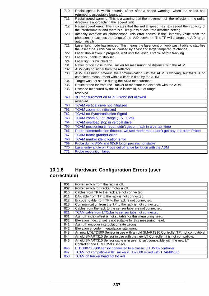
710 Radial speed is within bounds. (Sent after a speed warning when the speed has returned to acceptable bounds.)
71 Radial speed warning. This is a warning that the movement of the refledirection is approaching the speed limit.
1 ctor in the radial
712 Radial speed error. This indicates that the radial speed has exceeded the capacity of a likely loss of accurate distance setting. the interferometer and there is
720 Intensity overflow on photosensor. This error occurs, if the intensity value from the e of the A/D converter. The TP will change the A/D range photosensor exceeds the rang
automatically. 721 Laser light mode has jumped. This
the laser tube. (This can be caused means the laser control loop wasn’t able to stabilize
a fast and large temperature change). by 722 Laser stabilization in progress, wait until the laser is stable before tracking. 723 Laser is unable to stabilize. 724 Laser light is switched off. 731 Reflector too close to the Tracker for measuring the distance with the ADM. 732 ADM gets no signal from the reflector 733 ADM measuring timeout, the communication with the ADM is working, but there is no
a certain time by the ADM. completed measurment within 734 Target was not stable during the ADM measurement 735 Reflector too far from the Tracker to measure the distance with the ADM. 736 Distance measured by the ADM is invalid, out of range reserved 740 3D measurement on 6DoF-Probe not allowed reserved 760 TCAM vertical drive not initialized 761 TCAM zoom not initialized 762 TCAM no Synchronization Signal 763 TCAM zoom out of Range (1.5...15m) 764 TCAM overload stop in vertical drive 765 TCAM positioning timeout, didn’t get on track in a certain time 766 Probe communication timeout, we see markers but don’t get any Info from Probe 767 TCAM frame grabber error 768 TCAM marker identification error 769 Probe during ADM and 6DoF logon process not stable 770 Laser entry angle on Probe out of range for logon with the ADM 771 Probe recognition failed
10.1.8 (user orrectable
Power switch from the rack is off.
Hardware Configuration Errorsc ) 801 802 Power switch for tracker motor is off. 810 Cables from TP to the rack are not connected. 811 DA-cable from TP to the rack is not connected. 812 Encoder-cable from TP to the rack is not connected. 813 Communication from the TP to the rack is not connected. 820 Cables from the rack to the sensor tube are not connected. 821 TCAM cable from LTCplus to sensor tube not connected 831 Azimuth index offset is not suitable for this measuring head. 832 Elevation index offset is not suitable for this measuring head. 841 Azimuth encoder interpolation rate wrong 842 Elevation encoder interpolation rate wrong 843 An new LT/LTD500 Sensor in use with an old SMART310 Controller/TP, not compatible! 844 An old SMART310 Sensor in use with the new LT Controller, it is not compatible. 845 An old SMART310 Sensor cable is in use, it isn’t compatible with the new LT
Controller and LT/LTD500 Sensor. 846 LTD600/700/800 sensor connected to a classic (LTD500) controller 847 TCAM not compatible with Tracker (LTD7/800 mixed with TCAM8/700) 850 TCAM on tracker head not locked
337

10.1.9 s service personnel) Hardware Error (require 901 Azimuth axis is not working. 902 Elevation axis is not working. 903 Azimuth Tacho signal failed. 904 Elevation Tacho signal failed. 905 Azimuth encoder is not working. 906 Elevation encoder is not working. 907 Azimuth index mark does not respond. 908 Elevation index mark does not respond. 909 Azimuth moving range limited (can not move +/- 240 degrees). 910 Photo sensor is not working properly. 911 Photo sensor does not receive enough light. 912 Photo sensor intensity signal failed 913 Photo sensor X signal failed 914 Photo sensor Y signal failed 915 Calculation error while determining the SERVO CONTROL POINT. 916 No collar reflector found for measuring the servo control point. (or the beam intensity is
not strong enough to locate the collar reflector.). 917 Laser unable to stabilize, hardware error on the laser detected. 918 Interferometer is not working properly. (eg, at test into the collar reflector did not work) 919 ‘Lost counts’ signal of the interferometer is not working properly. 921 LAN, Command line switch error. 923 No LANtastic hardware detected. 924 LAN, Shared RAM did not pass tests. 925 LAN Coprocessor did not respond to reset. 927 LAN, Interrupt level error. 930 No encoder board detected. 931 Encoder board, Azimuth counter is not working. 932 Encoder board, Elevation counter is not working. 933 Encoder board, Interferometer counter is not working. 934 Encoder board, Azimuth index pulse failed. 935 Encoder board, Elevation index pulse failed. 93 Encoder board, Latch signal for counters failed. 6 93 Encoder board, disabling of index pulses failed. 7 938 Encoder board, cannot switch on the receiver for index pulses. 939 Encoder potentiometer adjustments, invalid. 940 No A/D board detected. 941 A/D board, Unipolar/Bipolar switch is set wrong. 942 A/D board, 8/16 channel switch is set wrong. 943 A/D board, Analog input multiplexor error. 944 A/D board, A/D converter is not working. 945 A/D board, DMA data transfer is not working. 946 A/D board, onboard clock is not working. 947 is set wrong. A/D board, Pacer clock too slow, switch 948 A/D board, Pacer trigger is not working. 949 A/D board, External trigger is not working. 950 orking. A/D board, A/D voltage range switch is not w 951 nce. A/D board, A/D input offset is out of tolera 952 r. A/D board, DMA transfer synchronization erro 953 DAC in wrong position A/D board, Ref. Voltage Jumper for 954 ce D/A board, zero point of DAC out of toleran 955 . D/A board, both axes not working 956 rking. D/A board, Azimuth axis not wo 957 D/A board, Elevation axis not working. 958 justed. Azimuth motor amplifier balance not properly ad 959 properly adjusted. Elevation motor amplifier balance not 960 reserved 961 CPU board, DMA controller failed. 962 CPU board, DMA controller wrap around error 963 reserved 964 CPU board, CPU clock too slow. 968 allocation. CPU board, not enough memory for dynamic memory 969 reserved
338

970 cted. LTC, internal PSD input cable not conne 971 LTC, internal Motor I/O cable not connected. 972 LTC Digital I/O cable not connected. 973 LTC, COM1 cable not connected 974 LTC, COM2 cable not connected 975 LTC, Az Encoder Cable not connected 976 connected LTC, El Encoder cable not 977 C card not connected LTC, Cable between A/D board and LT 978 oder card not connected LTC, HW Trigger cable LTC card to Enc 979 Amplifier to Encoder Card not connected LTCplus, Encoder Latch Cable, Motor 980 LTC, +5V Power Supply failed 981 LTC, +7V Power Supply failed 982 LTC, +12V Power Supply failed 983 LTC, +28V Power Supply failed 984 LTC, -5V Reference voltage failed 985 LTC, -7V Power Supply failed 986 LTC, -12V Power Supply failed 987 orking LTC, Inhibit of 28V Power Supply not w 988 LTC, +15V Power Supply failed 989 LTC, -15V Power Supply failed 990 LTC, Tacho Power Supply failed (located in the measuring head) 991 LTC, 2.5/3.3V Supply failed on LTC Card 992 LTCplus, +5V Supply failed on Motor Amplifier 993 r LTCplus, +12V Supply failed on Motor Amplifie 994 r LTCplus, -12V Supply failed on Motor Amplifie 995 LTCplus, +3.3V Supply failed on Tracker Server (emScon) 996 con) LTCplus, +12V Supply failed on Tracker Server (emS 997 Scon) LTCplus, -12V Supply failed on Tracker Server (em 998 LTCplus, Power for FAN’s on Front Panel failed 999 Unknown hardware error.
10.2 ROR NUMBERS
e ID
T- PRODUCTS ER Uniqu Text 2150 MSGERR: ERROR, message table inconsistent (entry: %d)! 2151 MSGERR: ERROR, attachement ring buffer overrun! 2200 PARMGR: MESSAGE, New parameter initialisation! 2201 PARMGR: ERROR, CRC on parameter table! 2202 PARMGR: ERROR, not allowed range for this parameter! 2203 PARMGR: ERROR, unknown parameter id! 2204 PARMGR: REMARK, parameter table is full! 2205 PARMGR: WARNING, table size defined in code and that saved in flash differs 2206 PARMGR: WARNING, error occure during load! 2207 PARMGR: ERROR, error occure during save! 2208 PARMGR: ERROR, invalid command parameter ! 2210 PARTBL: ERROR, flash table not found 2211 PARTBL: ERROR, invalid table block number! 2212 PARTBL: ERROR, invalid table data! 3000 CMDI: ERROR, unknown keyword! 3003 CMDI: ERROR, not allowed command in this mode! 3004 CMDI: ERROR, to long string parameter! 3050 DCSC: ERROR, wrong value for T-Cam mode! 3052 DSPHL: ERROR, timeout during V_INIT command 3054 DSPHL: ERROR, timeout during V_INFO command ! 3110 TGT: Command parameter invalid - command not executed 3111 TGT: FGIF data invalid - data block discarded 3112 TGT: Section list overflow - line discarded
339
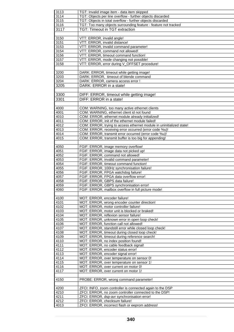
3113 TGT: Invalid image item - data item skipped 3114 TGT: Objects per line overflow - further objects discarded 3115 TGT: Objects in total overflow - further objects discarded 3116 TGT: Too many objects surrounding feature - feature not tracked 3117 TGT: Timeout in TGT extraction 3150 VTT: ERROR, invalid angle! 3151 VTT: ERROR, invalid distance! 3153 VTT: ERROR, invalid command parameter! 3154 VTT: ERROR, command not allowed! 3156 TT: ERROR, timeout command function! V3157 VTT: ERROR, mode changing not possible! 3158 VTT: ERROR, error during V_OFFSET procedure! 3200 DARK: ERROR, timeout while getting image! 3203 ARK: ERROR, timeout of blende command D3204 DARK: ERROR, camera access error ! 3205 ARK: ERROR in a state! D 3300 DIFF: ERROR, timeout while getting image! 3301 DIFF: ERROR in a state! 4000 COM: WARNING, too many active ethernet clients 4001 COM: WARNING, ethernet client id not found 4010 COM: ERROR, ethernet module already initialized! 4011 COM: ERROR, init of the ethernet module failed! 4012 COM: ERROR, trying to access ethernet module in uninitialized state! 4013 COM: ERROR, receiving error occurred (error code %u)! 4014 COM: ERROR, transmit error occurred (error code %u)! 4015 COM: ERROR, transmit buffer is too big for appending! 4050 FGIF: ERROR, image memory overflow! 4051 FGIF: ERROR, image data not picked up! 4052 FGIF: ERROR, command not allowed! 4053 FGIF: ERROR, invalid command parameter! 4054 FGIF: ERROR, timeout command function! 4055 FGIF: ERROR, 100Hz synchronisation failure! 4056 FGIF: ERROR, FPGA watchdog failure! 4057 FGIF: ERROR, FPGA data overflow error! 4058 FGIF: ERROR, GBPS data failure! 4059 FGIF: ERROR, GBPS synchronisation error! 4060 FGIF: ERROR, mailbox overflow in full picture mode! 4100 MOT: ERROR, encoder failure! 4101 MOT: ERROR, wrong encoder counter direction! 4102 MOT: ERROR, motor controller failure! 4103 MOT: ERROR, motor unit is blocked or braked! 4104 MOT: ERROR, reflexion sensor failure! 4105 MOT: ERROR, unknown error in open loop check! 4106 MOT: ERROR, function call not allowed! 4107 MOT: ERROR, standstill error while closed loop check! 4108 MOT: ERROR, timeout during closed loop check! 4109 MOT: ERROR, timeout during reference search! 4110 MOT: ERROR, no index position found! 4111 MOT: ERROR, no cable feedback signal! 4112 MOT: ERROR, encoder status error! 4113 MOT: ERROR, encoder signal error! 4114 MOT: ERROR, over temperature on sensor 0! 4115 MOT: ERROR, over temperature on sensor 1! 4116 MOT: ERROR, over current on motor 0! 4117 MOT: ERROR, over current on motor 1! 4150 PROBE: ERROR, wrong command parameter! 4200 ZFCI: INFO, zoom controller is connected again to the DSP 4210 ZFCI: ERROR, no zoom controller connected to the DSP! 4211 ZFCI: ERROR, dsp-avr synchronisation error! 4212 ZFCI: ERROR, checksum failure! 4013 ZFCI: ERROR, incorrect flash or eeprom address!
340

341
4014 ZFCI: ERROR, flash or eeprom address already written! 4215 ZFCI: ERROR, zoom controller reports an error - command not executed! 4216 ZFCI: ERROR, command may not be executed at the moment! 4217 ZFCI: ERROR, invalid command parameter! 4218 ZFCI: ERROR, wrong ZFC answer! 4250 FLASH: REMARK, space in err/log message sector is running out 4251 FLASH: REMARK, err/log message sector erased successfully 4260 FLASH: ERROR, err/log message sector erase failed! 4261 FLASH: ERROR, writing of a err/log message failed! 4350 SPI: ERROR, Receive timeout occurred! 4351 SPI: ERROR, Transmit channel not ready! 4400 SYNCH: ERROR, No external synch input received! 4450 CCIR: ERROR, invalid command parameter! 4500 FLTABHD: REMARK, parameter table is empty! 4501 FLTABHD: REMARK, recovery of the corresponding table failed! 4502 FLTABHD: WARNING, read parameter table is not valid! 4510 FLTABHD: ERROR, FLASH write error! 4511 FLTABHD: ERROR, FLASH read error! 4512 FLTABHD: ERROR, reset of a parameter table failed! 4513 FLTABHD: ERROR, module initialization failed or was not done! 4514 FLTABHD: ERROR, malloc error occurred! 4515 FLTABHD: ERROR, parameter table write error (crc check was not successful)! 4516 FLTABHD: ERROR, sector erase error! 4550 CAM: ERROR, invalid Z_CAMCOM answer! 4551 CAM: ERROR, no valid camera FPGA version!
EmScon 2.1 TPI Programmers Manual - Revison: April 27, 2005