Embed Size (px)
Citation preview
Railway Group Standard GC/RT5021 Issue Five Date December 2011
Track System Requirements
Synopsis This document mandates requirements for track geometry, track system, track components and switches and crossings (S&C) to provide for the safe guidance and support of rail vehicles.
Copyright in the Railway Group Standards is owned by
Rail Safety and Standards Board Limited. All rights are hereby reserved. No Railway Group Standard (in whole or in part) may be reproduced, stored in a retrieval system, or transmitted, in any form or means, without the prior written permission of Rail Safety and Standards Board Limited, or as expressly permitted by law.
RSSB Members are granted copyright licence in accordance with the Constitution Agreement relating to Rail Safety and Standards Board Limited.
In circumstances where Rail Safety and Standards Board Limited has granted a particular person or organisation permission to copy extracts from Railway Group Standards, Rail Safety and Standards Board Limited accepts no responsibility for, nor any liability in connection with, the use of such extracts, or any claims arising therefrom. This disclaimer applies to all forms of media in which extracts from Railway Group Standards may be reproduced.
Published by: RSSB Block 2 Angel Square 1 Torrens Street London EC1V 1NY © Copyright 2011 Rail Safety and Standards Board Limited
Uncontrolled When Printed Document comes into force and supersedes GCRT5021 Iss 4 on 03/03/2012
Amendments to this document are published on RSSB Standards Catalogue http://www.rssb.co.uk/railway-group-standards

Page 2 of 49 RSSB
Railway Group Standard GC/RT5021 Issue Five Date December 2011
Track System Requirements
Issue record Issue Date Comments
One April 2000 Original document Superseded Railway Group Standard GC/RT5010 and GC/RT5017 with some further additions.
Two October 2003 Replaces issue one Incorporated changes advised in GC/GN5523 and requirements held in GC/RT5011 issue two, GC/RT5014 issue one and GC/RT5024 issue one.
Three April 2007 Replaces issue two Incorporates requirements held in GC/RT5014 issue two, GC/RT5022 issue two, and GI/RT7004 issue one. Requirements that do not meet the risk scope test set out in the Railway Group Standards Code (issue two, 2006) have been withdrawn.
Four December 2009 Small scale change, replaces issue three Sections 1.2.1, 2.11.6, 2.11.7, 2.11.8 and 4.8.1.2 are revised. Section 4.2 is deleted (requirement withdrawn).
Five 03 December 2011
Replaces issue four Revised requirements and new Appendices: Sections 2.5.8, 2.5.9 and 2.7.2 are revised. Sections 3.2.2 and 3.2.5 are open points. These are requirements that are yet to be specified. Appendices A, B, C, D, G and H are new. Withdrawn Appendix: Appendix A on rail profile 60 E 2 is withdrawn.
Amended sections or revised pages have been marked by a vertical black line in the adjacent margin.
Superseded documents The following Railway Group documents are superseded, either in whole or in part as indicated:
Superseded documents Sections superseded
Date when sections are superseded
GC/RT5021, issue four, December 2009 Track System Requirements
All 03 March 2012
GC/RT5021 issue four ceases to be in force and is withdrawn as of 03 March 2012.
Uncontrolled When Printed Document comes into force and supersedes GCRT5021 Iss 4 on 03/03/2012
Amendments to this document are published on RSSB Standards Catalogue http://www.rssb.co.uk/railway-group-standards

RSSB Page 3 of 49
Railway Group Standard GC/RT5021 Issue Five Date December 2011
Track System Requirements
Supply The authoritative version of this document is available at www.rgsonline.co.uk. Uncontrolled copies of this document can be obtained from Communications, RSSB, Block 2, Angel Square, 1 Torrens Street, London EC1V 1NY, telephone 020 3142 5400 or e-mail [email protected]. Other Standards and associated documents can also be viewed at www.rgsonline.co.uk.
Uncontrolled When Printed Document comes into force and supersedes GCRT5021 Iss 4 on 03/03/2012
Amendments to this document are published on RSSB Standards Catalogue http://www.rssb.co.uk/railway-group-standards
Page 4 of 49 RSSB
Railway Group Standard GC/RT5021 Issue Five Date December 2011
Track System Requirements
Contents Section Description Page
Part 1 Purpose and Introduction 61.1 Purpose 61.2 Introduction 61.3 Approval and authorisation of this document 7
Part 2 Requirements for Track Geometry 82.1 Normal limiting design values and exceptional limiting design values 82.2 General horizontal alignment requirements 82.3 Permissible speed 82.4 Enhanced permissible speed 92.5 Circular curves 92.6 Transition curves 132.7 Vertical alignment 142.8 Track geometry requirements for sidings 152.9 Track gauge 162.10 Rail inclination 172.11 Track geometry faults 17
Part 3 Requirements for the Track System and Components 213.1 Performance specification for the track system 213.2 Requirements for rails, rail gaps and rail fastenings 213.3 Performance requirements for trackbed 24
Part 4 Particular Requirements for S&C 254.1 Identification of points 254.2 Facing point locking 254.3 Detection of points 264.4 Flangeway and track gauge in points 274.5 Particular requirements for train operated points 274.6 Limits on wear and damage to switches, switch diamonds and swing nose
crossings 284.7 Requirements for crossings 28
Part 5 Application of this Document 305.1 Application - infrastructure managers 305.2 Application - railway undertakings 325.3 Health and safety responsibilities 32
Appendices Appendix A Open Points 33Appendix B Guidance on Vertical Alignment 34Appendix C Explanatory Note: Requirements for Twist Faults 35Appendix D Open Points: Industry Practice Relating to Rail Profile 36Appendix E Guidance on Identification of Points 37Appendix F Free Wheel Passage and Flangeway in Switches 38Appendix G Explanatory Note: Requirements for Flangeway in Switches 39Appendix H Guidance on the use of Fixed Obtuse Crossings 40
Definitions 41
References 49
Uncontrolled When Printed Document comes into force and supersedes GCRT5021 Iss 4 on 03/03/2012
Amendments to this document are published on RSSB Standards Catalogue http://www.rssb.co.uk/railway-group-standards
RSSB Page 5 of 49
Railway Group Standard GC/RT5021 Issue Five Date December 2011
Track System Requirements
Tables Table 1 Maximum theoretical cant deficiency at switch toes 11Table 2 Minimum action on discovery of twist fault 17Table 3 Track gauge maintenance limits 17Table 4 Maintenance limits of track gauge within moving areas of S&C 18Table 5 Top fault limits 18Table 6 Lateral alignment fault limits 19Table 7 ‘Maximum’ and ‘very poor’ standard deviations 20Table 8 Minimum permitted rail head width resulting from sidewear 22Table 9 Wear limits to prevent wheel / fishplate strikes 22Table 10 Maximum speed of trains over rail gaps 23Table A.1 List of open points 33
Figures Figure F.1 Free wheel passage and indication of flangeway in switches 38
Uncontrolled When Printed Document comes into force and supersedes GCRT5021 Iss 4 on 03/03/2012
Amendments to this document are published on RSSB Standards Catalogue http://www.rssb.co.uk/railway-group-standards
Page 6 of 49 RSSB
Railway Group Standard GC/RT5021 Issue Five Date December 2011
Track System Requirements
Part 1 Purpose and Introduction 1.1 Purpose
1.1.1 This document mandates requirements for track geometry, track system, track components and S&C to provide for the safe guidance and support of rail vehicles.
1.2 Introduction 1.2.1 Principles
1.2.1.1 The requirements of this document are based on one or more of the following principles:
a) This document mandates those requirements that define the interface and the need for cooperation between different categories of duty holders to manage risk safely.
b) This document mandates requirements that are necessary to support an open point in a TSI and meet an essential requirement of the relevant European Directive.
c) This document contains ‘open points’, that is, requirements that have not yet been specified, but which are within scope of the document. These are listed in Appendix A, which also indicates where additional information on industry practice relating to each open point may be found.
1.2.2 Related requirements in other documents 1.2.2.1 The following Railway Group Standards contain requirements that are relevant to
the scope of this document:
a) GC/RT5033 sets out requirements for buffer stops, arresting devices and end walls for terminal tracks.
b) GC/RT5212 mandates requirements for monitoring and maintaining clearances. It also mandates requirements for new, altered and temporary infrastructure relating to clearances; gauging conditions for passage of exceptional loads; standard vehicle gauges; and data relating to gauging and clearances, to be provided to Railway Group members and their suppliers. This document includes the requirements for position of check rails, guard rails and other equipment in the lower sector area.
c) GE/RT8012 mandates the means by which Tilting Trains may be operated at higher speeds than non-tilting trains around curves.
d) GI/RT7016 mandates requirements for the design and maintenance of station platforms for their safe interface with trains.
e) GK/RT0028 mandates the interface requirements to ensure that train detection systems provide the signalling system with adequate information regarding the position and movement of trains to permit safe control of the railway.
f) GM/RT2141 mandates requirements for rolling stock to ensure acceptable resistance against flange climbing derailment and against roll-over induced by overspeeding.
g) GM/RT2466 mandates requirements for the design, manufacture and maintenance of wheelsets and their components.
Uncontrolled When Printed Document comes into force and supersedes GCRT5021 Iss 4 on 03/03/2012
Amendments to this document are published on RSSB Standards Catalogue http://www.rssb.co.uk/railway-group-standards

RSSB Page 7 of 49
Railway Group Standard GC/RT5021 Issue Five Date December 2011
Track System Requirements
h) GM/TT0088 prescribes design and maintenance requirements for traction and rolling stock and for on-track plant to ensure that interactive forces and stresses generated between vehicles and track are limited to acceptable levels. Vehicle performance limits relating to wheel loads, wheel diameters, unsprung masses and suspension characteristics are specified.
1.2.3 Supporting documents 1.2.3.1 GC/RC5521 sets out an approved method of calculating enhanced permissible
speeds for tilting trains.
1.3 Approval and authorisation of this document 1.3.1 The content of this document was approved by Infrastructure Standards
Committee on 14 September 2011.
1.3.2 This document was authorised by RSSB on 24 October 2011.
Uncontrolled When Printed Document comes into force and supersedes GCRT5021 Iss 4 on 03/03/2012
Amendments to this document are published on RSSB Standards Catalogue http://www.rssb.co.uk/railway-group-standards
Page 8 of 49 RSSB
Railway Group Standard GC/RT5021 Issue Five Date December 2011
Track System Requirements
Part 2 Requirements for Track Geometry 2.1 Normal limiting design values and exceptional limiting design values
2.1.1 This section sets out normal limiting design values and exceptional limiting design values for track geometry parameters.
2.1.2 Where site conditions allow, normal limiting design values shall be used for all parameters.
2.1.3 Where the speed requirements cannot be met by using normal limiting design values it is permissible to use exceptional limiting design values. The reason and implications for their use shall be justified.
2.1.4 When a design value is quoted without being described as either normal or exceptional, it is the only limiting value and no exceptional limiting value is permitted.
2.1.5 Exceptional limiting design values shall not be exceeded.
2.2 General horizontal alignment requirements 2.2.1 On running lines, horizontal alignments shall consist of circular curves and
straight track connected where necessary by transition curves. The minimum length of each geometrical element shall be appropriate to the length and characteristics of vehicles likely to use the track.
2.2.2 Restrictions on the location of station platforms in relation to the horizontal alignment of track are set out in GI/RT7016.
2.2.3 The requirements for the alignment of track at buffer stops and arresting devices are set out in GC/RT5033.
2.3 Permissible speed 2.3.1 The permissible speed on a curve shall be calculated taking account of the
following factors:
a) The radius of the curve.
b) The applied cant.
c) The permitted values of cant deficiency.
d) The permitted values of rates of change of cant and cant deficiency on the transition curves either side of the circular curve.
2.3.2 There could be reasons other than track geometry design that restrict the permissible speed, for example the ability to maintain the track to sufficiently high track quality standards, the nature of the signalling system, or the strength of structures.
Uncontrolled When Printed Document comes into force and supersedes GCRT5021 Iss 4 on 03/03/2012
Amendments to this document are published on RSSB Standards Catalogue http://www.rssb.co.uk/railway-group-standards
RSSB Page 9 of 49
Railway Group Standard GC/RT5021 Issue Five Date December 2011
Track System Requirements
2.4 Enhanced permissible speed 2.4.1 Calculation of enhanced permissible speed
2.4.1.1 The conditions under which trains are permitted to travel at an enhanced permissible speed are set out in GE/RT8012.
2.4.1.2 The enhanced permissible speed shall be calculated for each type of train on each curve. The speed on each track of a double or multiple line shall be considered separately. On bi-directional tracks, the speed in each direction shall be considered separately.
2.4.1.3 A procedure shall be in place for calculating enhanced permissible speeds. The procedure shall set out the method of gaining technical approval for the calculated enhanced permissible speed.
2.4.1.4 The calculation of enhanced permissible speed shall take account of the factors listed in 2.3.1 together with the following additional factors:
a) The maximum cant deficiency at which the train is designed to travel.
b) The dynamic roll-over resistance of the train (see GM/RT2141).
c) The maintenance tolerances on cant (the amount by which, in practice, the applied cant could be less than its design value).
d) The maintenance tolerances on curvature (the amount by which, in practice, the curve radius could be less than its design value).
e) The expected local wind conditions.
f) The effect of wind on the train, taking into account the characteristics of the train (see GM/RT2142).
g) The system adopted for controlling the speed of the train and the extent to which overspeed can occur (see GE/RT8012).
h) A safety margin equivalent to no less than 50 mm of cant deficiency.
2.4.1.5 The enhanced permissible speed shall ensure that the likelihood of overturning is within tolerable limits.
2.4.2 Enhanced permissible speed for S&C 2.4.2.1 Enhanced permissible speeds shall not be permitted on the turnout route of S&C.
2.5 Circular curves 2.5.1 Minimum radii
2.5.1.1 Horizontal curve radii shall be selected to take account of the curving characteristics of vehicles likely to use the track.
2.5.1.2 The normal minimum radius on passenger running lines shall be 200 m.
2.5.1.3 The exceptional minimum radius on passenger running lines shall be 150 m.
2.5.1.4 The normal minimum radius on non-passenger running lines shall be 150 m.
2.5.1.5 The exceptional minimum radius on non-passenger running lines shall be 125 m.
Uncontrolled When Printed Document comes into force and supersedes GCRT5021 Iss 4 on 03/03/2012
Amendments to this document are published on RSSB Standards Catalogue http://www.rssb.co.uk/railway-group-standards
Page 10 of 49 RSSB
Railway Group Standard GC/RT5021 Issue Five Date December 2011
Track System Requirements
2.5.2 Reverse curves 2.5.2.1 A length of straight track not less than 3 m long shall be provided between the
reverse curves if one of the curves has a radius of less than 160 m.
2.5.3 Normal limiting design values for cant 2.5.3.1 The normal limiting design values for cant shall be:
a) 110 mm adjacent to station platforms.
b) 110 mm on fixed obtuse crossings.
c) 150 mm elsewhere.
2.5.4 Exceptional limiting design values for cant 2.5.4.1 The exceptional limiting design values for cant shall be:
a) 130 mm adjacent to station platforms.
b) 110 mm on fixed obtuse crossings (unchanged from normal limiting design value).
c) 180 mm elsewhere.
2.5.5 Cant on curves with radii less than 320 m 2.5.5.1 The cant on curves with radii less than 320 m shall not exceed Cmax, where Cmax
a) C
is given by the lesser of:
max = (R - 50) / 1.5, where Cmax
b) C
is in millimetres and R is the curve radius in metres.
max
2.5.6 Negative cant
= the normal limiting design value set out in 2.5.3.
2.5.6.1 Negative cant shall only be permitted on the turnout route through S&C and in the plain line immediately adjoining the S&C. On fixed obtuse crossings the normal limiting design value for negative cant shall be zero and the exceptional limiting design value shall be 65 mm. Elsewhere negative cant shall not exceed 80 mm.
2.5.7 Normal limiting design values for cant deficiency at permissible speed 2.5.7.1 The normal limiting design values for cant deficiency shall be:
a) 110 mm on plain line on continuous welded rail (CWR).
b) 110 mm on the through route of S&C designed for use in CWR without adjustment switches.
c) 110 mm on the turnout route of S&C where designed to accommodate this value of cant deficiency.
d) 75 mm on fixed obtuse crossings.
e) 90 mm elsewhere.
Uncontrolled When Printed Document comes into force and supersedes GCRT5021 Iss 4 on 03/03/2012
Amendments to this document are published on RSSB Standards Catalogue http://www.rssb.co.uk/railway-group-standards
RSSB Page 11 of 49
Railway Group Standard GC/RT5021 Issue Five Date December 2011
Track System Requirements
2.5.8 Exceptional limiting design values for cant deficiency at permissible speed 2.5.8.1 An exceptional limiting design value for cant deficiency on plain line jointed track
of 110 mm is permissible for diesel multiple units with axle weights less than 13 t design mass under normal payload (as set out in BS EN 15663:2009) and fitted with bogies and air suspension, provided:
a) The intrinsic track quality has been assessed and is considered suitable.
b) The condition of rail joints has been assessed and is considered suitable.
2.5.8.2 An exceptional limiting design value for cant deficiency on plain line CWR of 150 mm is permissible for vehicles, other than freight vehicles, accepted for running at this cant deficiency, provided no features likely to contribute to lateral misalignment are situated on the transition or circular curve. Features considered likely to contribute to lateral misalignment shall include catch points, adjustment switches, level crossings, longitudinal timbers and directly fastened track on bridges.
2.5.9 Normal limiting design values for cant deficiency at switch toes 2.5.9.1 It is permissible for the theoretical cant deficiency at switch toes to exceed the
normal limiting design values set out in 2.5.7 but shall not exceed the values set out in Table 1. In order to assess the permissible speed it is necessary to calculate the radius at the switch toe. The radius shall be obtained by calculating the offset at the toe based on a 12.2 m chord centred about the switch toe.
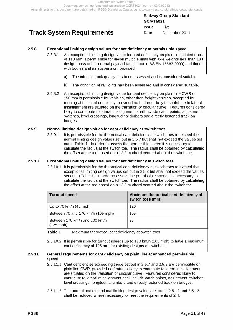
2.5.10 Exceptional limiting design values for cant deficiency at switch toes 2.5.10.1 It is permissible for the theoretical cant deficiency at switch toes to exceed the
exceptional limiting design values set out in 2.5.8 but shall not exceed the values set out in Table 1. In order to assess the permissible speed it is necessary to calculate the radius at the switch toe. The radius shall be obtained by calculating the offset at the toe based on a 12.2 m chord centred about the switch toe.
Turnout speed Maximum theoretical cant deficiency at switch toes (mm)
Up to 70 km/h (43 mph) 120
Between 70 and 170 km/h (105 mph) 105
Between 170 km/h and 200 km/h (125 mph)
85
Table 1 Maximum theoretical cant deficiency at switch toes
2.5.10.2 It is permissible for turnout speeds up to 170 km/h (105 mph) to have a maximum cant deficiency of 125 mm for existing designs of switches.
2.5.11 General requirements for cant deficiency on plain line at enhanced permissible speed 2.5.11.1 Cant deficiencies exceeding those set out in 2.5.7 and 2.5.8 are permissible on
plain line CWR, provided no features likely to contribute to lateral misalignment are situated on the transition or circular curve. Features considered likely to contribute to lateral misalignment shall include catch points, adjustment switches, level crossings, longitudinal timbers and directly fastened track on bridges.
2.5.11.2 The normal and exceptional limiting design values set out in 2.5.12 and 2.5.13 shall be reduced where necessary to meet the requirements of 2.4.
Uncontrolled When Printed Document comes into force and supersedes GCRT5021 Iss 4 on 03/03/2012
Amendments to this document are published on RSSB Standards Catalogue http://www.rssb.co.uk/railway-group-standards

Page 12 of 49 RSSB
Railway Group Standard GC/RT5021 Issue Five Date December 2011
Track System Requirements
2.5.12 Normal limiting design values for cant deficiency on plain line at enhanced permissible speed 2.5.12.1 The normal limiting design values for cant deficiency at enhanced permissible
speed shall be:
a) 110 mm for curves under 400 m radius.
b) 185 mm for curve radii less than 700 m but greater than or equal to 400 m.
c) 265 mm for curve radii greater than or equal to 700 m.
2.5.13 Exceptional limiting design values for cant deficiency on plain line at enhanced permissible speed 2.5.13.1 The exceptional limiting design values for cant deficiency at enhanced
permissible speed shall be:
a) 150 mm for curves under 400 m radius.
b) 225 mm for curve radii less than 700 m but greater than or equal to 400 m.
c) 300 mm for curve radii greater than or equal to 700 m.
2.5.14 Normal limiting design values for cant deficiency on the through route of S&C at enhanced permissible speed 2.5.14.1 The normal limiting design values for cant deficiency on the through route of S&C
shall be the same as those at permissible speed set out in 2.5.7. Exceptionally, a cant deficiency higher than the normal limiting design value is permissible on S&C designed for use in CWR without adjustment switches, up to a limit of 200 mm, provided the radius is greater than or equal to 400 m.
2.5.14.2 Where cant deficiency above 110 mm is proposed, the use of S&C requiring adjustment switches is not permitted.
2.5.14.3 Where cant deficiency above 150 mm is proposed, additional special features shall be incorporated that eliminate discontinuities at crossings.
2.5.15 Exceptional limiting design values for cant deficiency on the through route of S&C at enhanced permissible speed 2.5.15.1 The exceptional limiting design values for cant deficiency on the through route of
S&C shall be the same as those at permissible speed set out in 2.5.8. Exceptionally, a cant deficiency higher than the exceptional limiting design value is permissible on S&C designed for use in CWR without adjustment switches, up to a limit of 200 mm, provided the radius is greater than or equal to 400 m.
2.5.15.2 Where cant deficiency above 110 mm is proposed, the use of S&C requiring adjustment switches is not permitted.
2.5.15.3 Where cant deficiency above 150 mm is proposed, additional special features shall be incorporated that eliminate discontinuities at crossings.
Uncontrolled When Printed Document comes into force and supersedes GCRT5021 Iss 4 on 03/03/2012
Amendments to this document are published on RSSB Standards Catalogue http://www.rssb.co.uk/railway-group-standards
RSSB Page 13 of 49
Railway Group Standard GC/RT5021 Issue Five Date December 2011
Track System Requirements
2.6 Transition curves 2.6.1 General requirements for transition curves
2.6.1.1 Where possible, a transition curve shall be provided between two circular curves or between a circular curve and straight track. Curvature shall increase (or decrease) regularly over the whole length of the transition curve.
2.6.1.2 Where it is not possible to provide a transition curve, the permissible speed shall be calculated assuming a virtual transition 12.2 m long.
2.6.1.3 Designs of transition curves shall take the permissible speed and any enhanced permissible speeds into account, together with the cant and radius on adjoining curves.
2.6.1.4 On all transition curves, cant shall be proportional to the instantaneous curvature. The instantaneous cant gradient at any point shall not exceed the value set out in 2.6.4.
2.6.1.5 There are a large number of differing transition curve forms. Whichever form is chosen, curvature shall increase (or decrease) regularly over the whole length of the transition curve.
2.6.1.6 On transitions between reverse curves with no intervening straight, the point of zero cant shall coincide with the reverse point (point of zero curvature). Where possible, the rates of change of cant, cant deficiency and curvature shall be approximately the same on either side of the reverse curve. The same type of transition shall be used on either side of the reverse curve.
2.6.2 Particular requirements for clothoid spiral transition curves 2.6.2.1 The clothoid spiral (or its close approximation, the cubic parabola) is the usual
form of transition curve used on the mainline railway. The limiting values for rates of change of cant and rates of change of cant deficiency set out in 2.6.5 to 2.6.9 assume a clothoid spiral transition curve.
2.6.3 Particular requirements for forms of transition curves other than clothoid spiral 2.6.3.1 A transition curve other than a clothoid spiral is only permissible if a compatibility
assessment demonstrates that the chosen form of transition curve is compatible with vehicle tilting mechanisms.
2.6.3.2 The peak rate of change of cant and the peak rate of cant deficiency shall be specified to suit the degree of smoothing offered by the form of the transition curve. The average rate of change of cant deficiency through the transition curve shall comply with the values set out in 2.6.5 to 2.6.8, but it is permissible for the peak rate of change of cant deficiency to exceed the quoted values. However, the peak rate of change of cant deficiency shall not exceed these values by more than 33%.
2.6.4 Cant gradient 2.6.4.1 The steepest permitted designed cant gradient shall be 1 in 400.
2.6.4.2 The deflection of the track at skew underbridges during the passage of trains shall be taken into account when proposing to install cant gradients approaching 1 in 400.
2.6.5 Rate of change of cant at permissible speed 2.6.5.1 The normal limiting design value for rate of change of cant shall be 55 mm/s.
2.6.5.2 The exceptional limiting design value for rate of change of cant shall be 85 mm/s.
Uncontrolled When Printed Document comes into force and supersedes GCRT5021 Iss 4 on 03/03/2012
Amendments to this document are published on RSSB Standards Catalogue http://www.rssb.co.uk/railway-group-standards
Page 14 of 49 RSSB
Railway Group Standard GC/RT5021 Issue Five Date December 2011
Track System Requirements
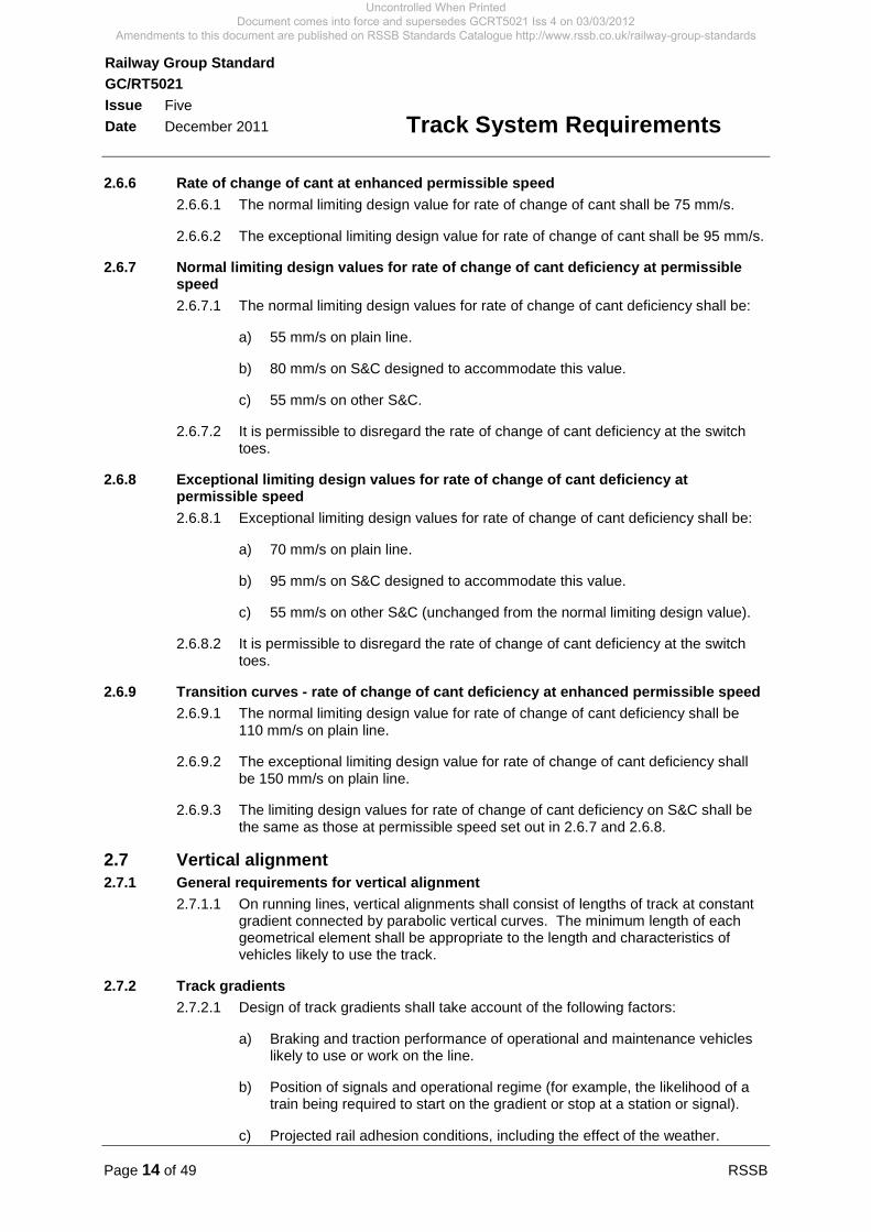
2.6.6 Rate of change of cant at enhanced permissible speed 2.6.6.1 The normal limiting design value for rate of change of cant shall be 75 mm/s.
2.6.6.2 The exceptional limiting design value for rate of change of cant shall be 95 mm/s.
2.6.7 Normal limiting design values for rate of change of cant deficiency at permissible speed 2.6.7.1 The normal limiting design values for rate of change of cant deficiency shall be:
a) 55 mm/s on plain line.
b) 80 mm/s on S&C designed to accommodate this value.
c) 55 mm/s on other S&C.
2.6.7.2 It is permissible to disregard the rate of change of cant deficiency at the switch toes.
2.6.8 Exceptional limiting design values for rate of change of cant deficiency at permissible speed 2.6.8.1 Exceptional limiting design values for rate of change of cant deficiency shall be:
a) 70 mm/s on plain line.
b) 95 mm/s on S&C designed to accommodate this value.
c) 55 mm/s on other S&C (unchanged from the normal limiting design value).
2.6.8.2 It is permissible to disregard the rate of change of cant deficiency at the switch toes.
2.6.9 Transition curves - rate of change of cant deficiency at enhanced permissible speed 2.6.9.1 The normal limiting design value for rate of change of cant deficiency shall be
110 mm/s on plain line.
2.6.9.2 The exceptional limiting design value for rate of change of cant deficiency shall be 150 mm/s on plain line.
2.6.9.3 The limiting design values for rate of change of cant deficiency on S&C shall be the same as those at permissible speed set out in 2.6.7 and 2.6.8.
2.7 Vertical alignment 2.7.1 General requirements for vertical alignment
2.7.1.1 On running lines, vertical alignments shall consist of lengths of track at constant gradient connected by parabolic vertical curves. The minimum length of each geometrical element shall be appropriate to the length and characteristics of vehicles likely to use the track.
2.7.2 Track gradients 2.7.2.1 Design of track gradients shall take account of the following factors:
a) Braking and traction performance of operational and maintenance vehicles likely to use or work on the line.
b) Position of signals and operational regime (for example, the likelihood of a train being required to start on the gradient or stop at a station or signal).
c) Projected rail adhesion conditions, including the effect of the weather.
Uncontrolled When Printed Document comes into force and supersedes GCRT5021 Iss 4 on 03/03/2012
Amendments to this document are published on RSSB Standards Catalogue http://www.rssb.co.uk/railway-group-standards
RSSB Page 15 of 49
Railway Group Standard GC/RT5021 Issue Five Date December 2011
Track System Requirements
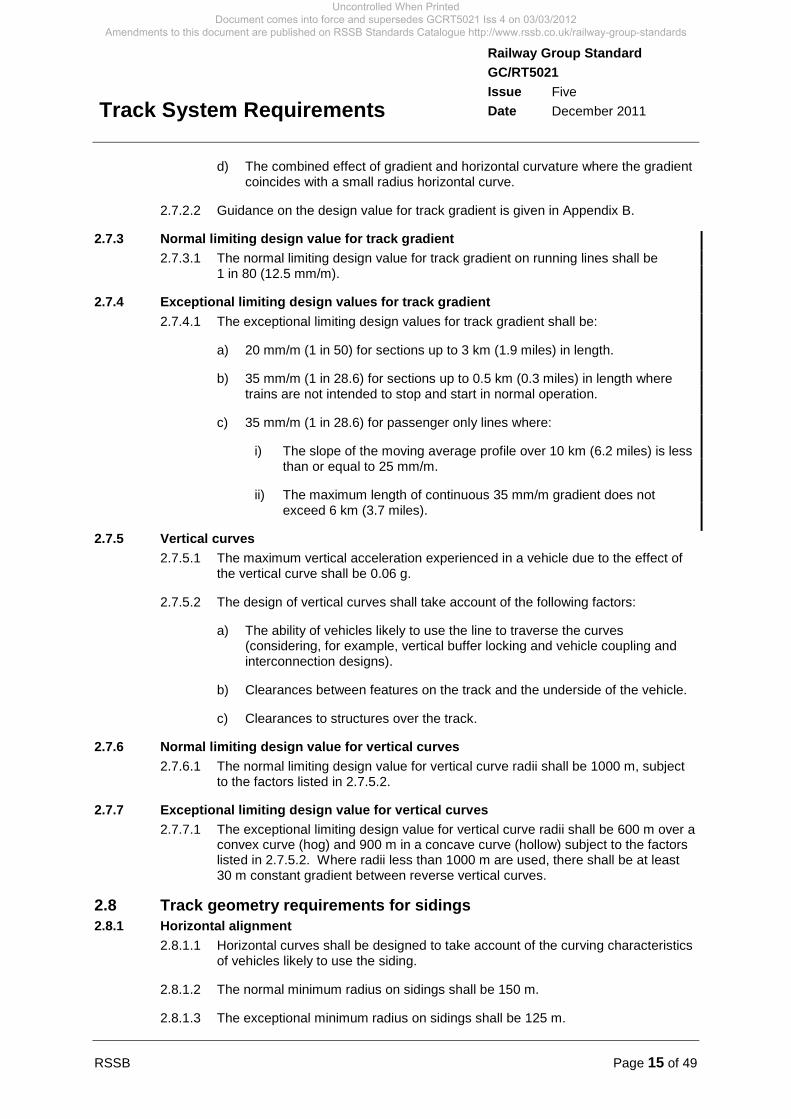
d) The combined effect of gradient and horizontal curvature where the gradient coincides with a small radius horizontal curve.
2.7.2.2 Guidance on the design value for track gradient is given in Appendix B.
2.7.3 Normal limiting design value for track gradient 2.7.3.1 The normal limiting design value for track gradient on running lines shall be
1 in 80 (12.5 mm/m).
2.7.4 Exceptional limiting design values for track gradient 2.7.4.1 The exceptional limiting design values for track gradient shall be:
a) 20 mm/m (1 in 50) for sections up to 3 km (1.9 miles) in length.
b) 35 mm/m (1 in 28.6) for sections up to 0.5 km (0.3 miles) in length where trains are not intended to stop and start in normal operation.
c) 35 mm/m (1 in 28.6) for passenger only lines where:
i) The slope of the moving average profile over 10 km (6.2 miles) is less than or equal to 25 mm/m.
ii) The maximum length of continuous 35 mm/m gradient does not exceed 6 km (3.7 miles).
2.7.5 Vertical curves 2.7.5.1 The maximum vertical acceleration experienced in a vehicle due to the effect of
the vertical curve shall be 0.06 g.
2.7.5.2 The design of vertical curves shall take account of the following factors:
a) The ability of vehicles likely to use the line to traverse the curves (considering, for example, vertical buffer locking and vehicle coupling and interconnection designs).
b) Clearances between features on the track and the underside of the vehicle.
c) Clearances to structures over the track.
2.7.6 Normal limiting design value for vertical curves 2.7.6.1 The normal limiting design value for vertical curve radii shall be 1000 m, subject
to the factors listed in 2.7.5.2.
2.7.7 Exceptional limiting design value for vertical curves 2.7.7.1 The exceptional limiting design value for vertical curve radii shall be 600 m over a
convex curve (hog) and 900 m in a concave curve (hollow) subject to the factors listed in 2.7.5.2. Where radii less than 1000 m are used, there shall be at least 30 m constant gradient between reverse vertical curves.
2.8 Track geometry requirements for sidings 2.8.1 Horizontal alignment
2.8.1.1 Horizontal curves shall be designed to take account of the curving characteristics of vehicles likely to use the siding.
2.8.1.2 The normal minimum radius on sidings shall be 150 m.
2.8.1.3 The exceptional minimum radius on sidings shall be 125 m.
Uncontrolled When Printed Document comes into force and supersedes GCRT5021 Iss 4 on 03/03/2012
Amendments to this document are published on RSSB Standards Catalogue http://www.rssb.co.uk/railway-group-standards

Page 16 of 49 RSSB
Railway Group Standard GC/RT5021 Issue Five Date December 2011
Track System Requirements
2.8.1.4 The need for a length of straight track or transition between small radius reverse curves shall be considered, taking account of the following factors:
a) The ability to traverse the curves of vehicles likely to use the sidings.
b) The likelihood of buffer locking.
c) Vehicle coupling designs.
2.8.1.5 A length of straight track not less than 3 m long shall be provided between the reverse curves if one of the curves has a radius of less than 160 m.
2.8.1.6 The requirements for the alignment of track at buffer stops and arresting devices are set out in GC/RT5033.
2.8.2 Vertical alignment 2.8.2.1 The track gradient of sidings where vehicles stand shall not be steeper than
1 in 500.
2.8.2.2 The minimum radius of vertical curves in sidings shall be 600 m over a convex curve (hog) and 900 m in a concave curve (hollow).
2.9 Track gauge 2.9.1 Nominal track gauge
2.9.1.1 New and re-laid track shall be designed to give a nominal track gauge of 1435 mm.
2.9.1.2 Maintenance limits for nominal track gauge are set out in 2.11.3 and 2.11.4.
2.9.2 Gauge widening 2.9.2.1 On curves less than 200 m radius consideration shall be given to widening the
track gauge, taking account of the following:
a) Characteristics of vehicles likely to use the track.
b) The length and location of the curve.
c) The applied cant.
2.9.2.2 Associated requirements for the provision of check rails are set out in 3.2.11.
2.9.2.3 Where track gauge is widened, the check flangeway dimension shall be increased to maintain the distance between the rubbing face of the check rail and the running edge of the opposite rail (including a crossing nose) at a nominal check gauge of 1391 mm.
2.9.2.4 Track gauge shall be widened by moving the inner rail away from the designed track centre line to ensure alignment continuity along the outer (steering) rail.
2.9.2.5 Values for gauge widening for the purpose of computer simulations designed to examine whether a vehicle has an acceptable resistance to flange climbing derailments at low speed is set out in Appendix C of GM/RT2141.
Uncontrolled When Printed Document comes into force and supersedes GCRT5021 Iss 4 on 03/03/2012
Amendments to this document are published on RSSB Standards Catalogue http://www.rssb.co.uk/railway-group-standards

RSSB Page 17 of 49
Railway Group Standard GC/RT5021 Issue Five Date December 2011
Track System Requirements
2.10 Rail inclination 2.10.1 In plain line track, rails shall have a nominal inclination of 1 in 20 towards the
track centre line.
2.10.2 In S&C, rails shall have a nominal inclination of 1 in 20 towards the track centre line or be vertical, depending on the design of S&C considered. Where rails in S&C are vertical, it is permissible for the rails in short lengths of adjacent plain line also to be vertical. To accommodate the change in verticality from inclined track to vertical track, twist rails or transition sleepers shall be used.
2.11 Track geometry faults 2.11.1 Corrective action
2.11.1.1 The corrective actions set out in 2.11.2 to 2.11.7 apply to isolated track faults (that is, they are not combined with other track faults).
2.11.1.2 When track faults are discovered in combination, the circumstances shall be reviewed and, if necessary, action that is more stringent shall be taken.
2.11.2 Twist faults 2.11.2.1 Twist faults (measured over 3 m) worse than 1 in 200 shall not be permitted to
remain in the track. When twist faults are discovered they shall be repaired within a timescale commensurate with the risk of derailment, which in any case shall not be less stringent than the timescales set out in Table 2. The rationale for this requirement is given in Appendix C.
Twist fault Action
1 in 90 or worse Stop all traffic immediately and correct fault
Between 1 in 91 and 1 in 125 Correct fault within 36 hours of discovery
Between 1 in 126 and 1 in 199 Radius < 400 m: Correct fault within one week of discovery Radius ≥ 400 m: Correct fault within two weeks of discovery
Table 2 Minimum action on discovery of twist fault
2.11.3 Track gauge in plain line 2.11.3.1 Track gauge shall be maintained within the limits set out in Table 3.
Speed (mph) Lower limit (mm) Upper limit (mm)
95 and above 1430 1450
65 to 90 1429 1450
25 to 60 1426 1455
Up to 20 1426 1465
Table 3 Track gauge maintenance limits
2.11.3.2 The speed used when determining the lower and upper track gauge limits for a section of track shall be the highest permissible or enhanced permissible speed over the section of track concerned.
Uncontrolled When Printed Document comes into force and supersedes GCRT5021 Iss 4 on 03/03/2012
Amendments to this document are published on RSSB Standards Catalogue http://www.rssb.co.uk/railway-group-standards

Page 18 of 49 RSSB
Railway Group Standard GC/RT5021 Issue Five Date December 2011
Track System Requirements
2.11.3.3 If a loaded track gauge of greater than 1480 mm is identified, all traffic shall be stopped immediately and action taken to strengthen the track to bring the loaded track gauge within the limits set out in Table 3.
2.11.4 Additional requirements for track gauge in S&C 2.11.4.1 Throughout the moveable length of switches, switch diamonds, and swing-nose
crossings, including the 100 mm in front of the switch toes, track gauge shall be maintained within limits required for the maintenance of point operating tolerances and in any case within the ranges set out in Table 4.
Type of S&C Lower limit (mm) Upper limit (mm)
Vertical 1430 1438
Bullhead or 109/110A/113A inclined
1433 1441
RT60/NR60 inclined 1433 1441
Table 4 Maintenance limits of track gauge within moving areas of S&C
2.11.4.2 Requirements relevant to the maintenance of point operating tolerances are set out in 4.2 and 4.3.
2.11.4.3 Requirements for flangeway and free wheel passage in switches are set out in 4.4.
2.11.4.4 Requirements for flangeway and check gauge for fixed crossings are set out in 4.7.2.
2.11.5 Cyclic top faults 2.11.5.1 A procedure shall be in place to determine the severity of cyclic top faults.
2.11.6 Vertical profile (top) faults 2.11.6.1 Where a top fault with a mean to peak value greater than that set out in Table 5 is
measured by a track recording vehicle, or where an equivalent fault is found by other means, the fault shall be repaired within a timescale commensurate with the likelihood of derailment.
Speed (mph) Value (mm)
105 and above 18
80 to 100 19
55 to 75 21
30 to 50 23
Up to 25 26
Table 5 Top fault limits
2.11.6.2 The speed used when determining the top fault limits for a section of track shall be the highest permissible or enhanced permissible speed over the section of track concerned.
Uncontrolled When Printed Document comes into force and supersedes GCRT5021 Iss 4 on 03/03/2012
Amendments to this document are published on RSSB Standards Catalogue http://www.rssb.co.uk/railway-group-standards

RSSB Page 19 of 49
Railway Group Standard GC/RT5021 Issue Five Date December 2011
Track System Requirements
2.11.7 Lateral alignment faults 2.11.7.1 Where a lateral alignment fault with a mean to peak value greater than that set
out in Table 6 is measured by a track recording vehicle, or where an equivalent fault is found by other means, the fault shall be repaired within a timescale commensurate with the likelihood of derailment.
Speed (mph) Value (mm)
105 and above 11
80 to 100 12
55 to 75 16
30 to 50 21
Up to 25 27
Table 6 Lateral alignment fault limits
2.11.7.2 The speed used when determining the lateral alignment fault limits for a section of track shall be the highest permissible or enhanced permissible speed over the section of track concerned.
2.11.8 Maximum and very poor standard deviations 2.11.8.1 The standard deviations of eighth mile sections shall be calculated from
measured data for each parameter listed below:
a) The vertical profile (top) of the rails, filtering out wavelengths greater than 35 m.
b) The lateral alignment of the rails, filtering out wavelengths greater than 35 m.
2.11.8.2 Where the permissible or enhanced permissible speed exceeds 75 mph the standard deviations of eighth mile sections shall be calculated from measured data for each parameter listed below:
a) The vertical profile (top) of the rails, filtering out wavelengths greater than 70 m.
b) The lateral alignment of the rails, filtering out wavelengths greater than 70 m.
2.11.8.3 The standard deviations for any section of track shall not normally exceed the ‘maximum’ standard deviations set out in Table 7.
2.11.8.4 When standard deviations greater than those shown as ‘very poor’ are measured, consideration shall be given to the need for action to improve track geometry.
2.11.8.5 Except in the case set out in 2.11.8.6, when standard deviations greater than the ‘maximum’ as set out in Table 7 are measured, action shall be taken to restore track geometry or impose a speed restriction at a level where the standard deviation is less than the maximum.
2.11.8.6 Where the alignment standard deviation is routinely greater than the ‘maximum’ as set out in Table 7, because of inherent design constraints and not because of track condition, the eighth mile section shall be reviewed and monitored to ensure safety and ride quality is not compromised. This exception applies to 35 m filter standard deviations only, where the permissible or enhanced permissible speed is 60 mph or less.
Uncontrolled When Printed Document comes into force and supersedes GCRT5021 Iss 4 on 03/03/2012
Amendments to this document are published on RSSB Standards Catalogue http://www.rssb.co.uk/railway-group-standards

Page 20 of 49 RSSB
Railway Group Standard GC/RT5021 Issue Five Date December 2011
Track System Requirements
Speed (mph)
Vertical profile standard deviation (mm)
Lateral alignment standard deviation (mm)
35 m filter 70 m filter 35 m filter 70 m filter
Maximum (eighth mile)
Very poor (eighth mile)
Very poor (eighth mile)
Maximum (eighth mile)
Very poor (eighth mile)
Very poor (eighth mile)
10-20 9.9 8.3 N/A 9.9 5.6 N/A
25-30 7.7 7.0 N/A 8.6 5.2 N/A
35-40 7.2 6.7 N/A 7.9 4.7 N/A
45-50 6.7 6.3 N/A 7.3 4.5 N/A
55-60 6.3 5.9 N/A 7.0 4.2 N/A
65-70 6.0 5.4 N/A 6.7 3.6 N/A
75-80 5.7 4.8 6.3* 6.3 3.1 5.7*
85-95 5.3 4.0 5.6 6.0 2.7 5.0
100-110 5.0 3.4 5.0 5.7 2.3 4.3
115-125 4.7 3.0 4.4 5.0 2.0 3.7
130-140 4.4 2.6 3.8 4.7 1.8 3.1
Table 7 ‘Maximum’ and ‘very poor’ standard deviations
* Applies to a speed of 80 mph only
2.11.8.7 The speed used when determining the ‘maximum’ standard deviations for a section of track shall be the highest permissible or enhanced permissible speed over the section of track concerned.
Uncontrolled When Printed Document comes into force and supersedes GCRT5021 Iss 4 on 03/03/2012
Amendments to this document are published on RSSB Standards Catalogue http://www.rssb.co.uk/railway-group-standards
RSSB Page 21 of 49
Railway Group Standard GC/RT5021 Issue Five Date December 2011
Track System Requirements
Part 3 Requirements for the Track System and Components
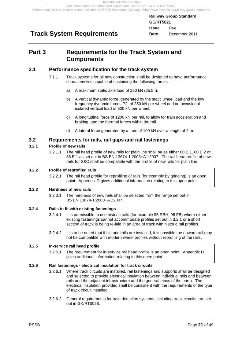
3.1 Performance specification for the track system 3.1.1 Track systems for all new construction shall be designed to have performance
characteristics capable of sustaining the following forces:
a) A maximum static axle load of 250 kN (25.5 t).
b) A vertical dynamic force, generated by the static wheel load and the low frequency dynamic forces P2, of 350 kN per wheel and an occasional isolated vertical load of 500 kN per wheel.
c) A longitudinal force of 1200 kN per rail, to allow for train acceleration and braking, and the thermal forces within the rail.
d) A lateral force generated by a train of 100 kN over a length of 2 m.
3.2 Requirements for rails, rail gaps and rail fastenings 3.2.1 Profile of new rails
3.2.1.1 The rail head profile of new rails for plain line shall be as either 60 E 1, 60 E 2 or 56 E 1 as set out in BS EN 13674-1:2003+A1:2007. The rail head profile of new rails for S&C shall be compatible with the profile of new rails for plain line.
3.2.2 Profile of reprofiled rails 3.2.2.1 The rail head profile for reprofiling of rails (for example by grinding) is an open
point. Appendix D gives additional information relating to this open point.
3.2.3 Hardness of new rails 3.2.3.1 The hardness of new rails shall be selected from the range set out in
BS EN 13674-1:2003+A1:2007.
3.2.4 Rails to fit with existing fastenings 3.2.4.1 It is permissible to use historic rails (for example 95 RBH, 98 FB) where either
existing fastenings cannot accommodate profiles set out in 3.2.1 or a short section of track is being re-laid in an area of track with historic rail profiles.
3.2.4.2 It is to be noted that if historic rails are installed, it is possible the unworn rail may not be compatible with modern wheel profiles without reprofiling of the rails.
3.2.5 In-service rail head profile 3.2.5.1 The requirement for in-service rail head profile is an open point. Appendix D
gives additional information relating to this open point.
3.2.6 Rail fastenings - electrical insulation for track circuits 3.2.6.1 Where track circuits are installed, rail fastenings and supports shall be designed
and selected to provide electrical insulation between individual rails and between rails and the adjacent infrastructure and the general mass of the earth. The electrical insulation provided shall be consistent with the requirements of the type of track circuit installed.
3.2.6.2 General requirements for train detection systems, including track circuits, are set out in GK/RT0028.
Uncontrolled When Printed Document comes into force and supersedes GCRT5021 Iss 4 on 03/03/2012
Amendments to this document are published on RSSB Standards Catalogue http://www.rssb.co.uk/railway-group-standards
Page 22 of 49 RSSB
Railway Group Standard GC/RT5021 Issue Five Date December 2011
Track System Requirements
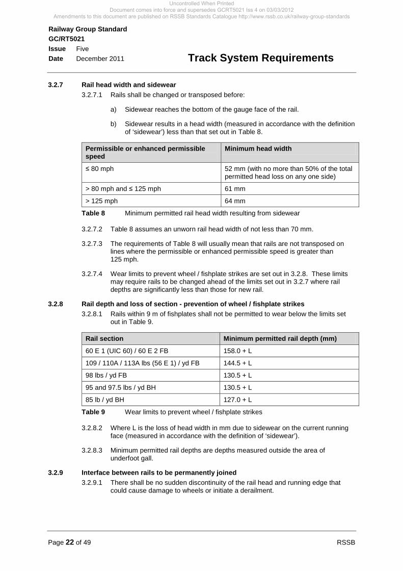
3.2.7 Rail head width and sidewear 3.2.7.1 Rails shall be changed or transposed before:
a) Sidewear reaches the bottom of the gauge face of the rail.
b) Sidewear results in a head width (measured in accordance with the definition of ‘sidewear’) less than that set out in Table 8.
Permissible or enhanced permissible speed
Minimum head width
≤ 80 mph 52 mm (with no more than 50% of the total permitted head loss on any one side)
> 80 mph and ≤ 125 mph 61 mm
> 125 mph 64 mm
Table 8 Minimum permitted rail head width resulting from sidewear
3.2.7.2 Table 8 assumes an unworn rail head width of not less than 70 mm.
3.2.7.3 The requirements of Table 8 will usually mean that rails are not transposed on lines where the permissible or enhanced permissible speed is greater than 125 mph.
3.2.7.4 Wear limits to prevent wheel / fishplate strikes are set out in 3.2.8. These limits may require rails to be changed ahead of the limits set out in 3.2.7 where rail depths are significantly less than those for new rail.
3.2.8 Rail depth and loss of section - prevention of wheel / fishplate strikes 3.2.8.1 Rails within 9 m of fishplates shall not be permitted to wear below the limits set
out in Table 9.
Rail section Minimum permitted rail depth (mm)
60 E 1 (UIC 60) / 60 E 2 FB 158.0 + L
109 / 110A / 113A lbs (56 E 1) / yd FB 144.5 + L
98 lbs / yd FB 130.5 + L
95 and 97.5 lbs / yd BH 130.5 + L
85 lb / yd BH 127.0 + L
Table 9 Wear limits to prevent wheel / fishplate strikes
3.2.8.2 Where L is the loss of head width in mm due to sidewear on the current running face (measured in accordance with the definition of ‘sidewear’).
3.2.8.3 Minimum permitted rail depths are depths measured outside the area of underfoot gall.
3.2.9 Interface between rails to be permanently joined 3.2.9.1 There shall be no sudden discontinuity of the rail head and running edge that
could cause damage to wheels or initiate a derailment.
Uncontrolled When Printed Document comes into force and supersedes GCRT5021 Iss 4 on 03/03/2012
Amendments to this document are published on RSSB Standards Catalogue http://www.rssb.co.uk/railway-group-standards

RSSB Page 23 of 49
Railway Group Standard GC/RT5021 Issue Five Date December 2011
Track System Requirements
3.2.9.2 To reduce the likelihood of wheel flange climbing, wheels shall not be allowed to pass from a sideworn rail to a less worn rail over a very short distance. Where a sideworn rail is to butt up to a new rail or a less sideworn rail at a fishplated or welded joint, the difference between the rail profiles shall be blended in by grinding. The blending shall meet the following requirements:
a) The less sideworn rail shall be blended in over a distance of at least 1.5 m from the joint.
b) The sidewear angle of the more sideworn rail shall be maintained throughout the blended length.
c) The gauge corner shall be rounded throughout the blended length to eliminate sharp or square edges.
3.2.10 Gaps between rail ends 3.2.10.1 Trains shall not be permitted to pass over gaps between rail ends at speeds
greater than those set out in Table 10.
Speed (mph) Gap (mm) Comments
90 and above 0 (nominal) CWR is required to satisfy this requirement. Nominal gaps are associated with tight joints and insulated joints.
Up to 90 Up to 15 In jointed track 15 mm represents maximum nominal expansion gap.
Up to 20 Up to 50 Used for engineering and emergency repair work.
Up to 5 Up to 75 Used for engineering and emergency repair work.
Trains not permitted Above 75 Line is blocked.
Table 10 Maximum speed of trains over rail gaps
3.2.10.2 The values set out in Table 10 are dependent on arrangements being in place to ensure the integrity and support of the rail.
3.2.11 Check rails on curves 3.2.11.1 All passenger lines, and freight only lines adjacent to passenger lines, with a
horizontal radius of 200 m or less shall be fitted with a continuous check rail to the inside rail of the curve, except where the design of S&C prevents this from being provided. The check rail shall extend at least 9 m into the straight or circular curve adjacent to the section of track with a radius of 200 m or less and its associated transitions.
3.2.11.2 All check rails shall have a machined or forged flare at each end of sufficient length to give guidance to vehicle wheel flanges entering the flangeway.
Uncontrolled When Printed Document comes into force and supersedes GCRT5021 Iss 4 on 03/03/2012
Amendments to this document are published on RSSB Standards Catalogue http://www.rssb.co.uk/railway-group-standards

Page 24 of 49 RSSB
Railway Group Standard GC/RT5021 Issue Five Date December 2011
Track System Requirements
3.3 Performance requirements for trackbed 3.3.1 General performance requirements
3.3.1.1 For new trackbed, a minimum dynamic sleeper support stiffness of 60 kN/mm per sleeper end shall be provided.
3.3.1.2 For trackbed renewal in areas with a history of poor track geometry, or where the vertical or horizontal alignment is to be changed significantly, a minimum dynamic sleeper support stiffness of 30 kN/mm per sleeper end shall be provided.
3.3.1.3 The design of trackbed layers shall address the need for transition zones where ballasted track abuts non-ballasted track or where a change in support stiffness beneath ballasted track prevents the required track geometry from being readily achieved.
Uncontrolled When Printed Document comes into force and supersedes GCRT5021 Iss 4 on 03/03/2012
Amendments to this document are published on RSSB Standards Catalogue http://www.rssb.co.uk/railway-group-standards
RSSB Page 25 of 49
Railway Group Standard GC/RT5021 Issue Five Date December 2011
Track System Requirements
Part 4 Particular Requirements for S&C 4.1 Identification of points 4.1.1 Point identity
4.1.1.1 Worked points, train operated points and unworked points that are detected in the signalling system shall have an identity that is unique to the controlling interlocking.
4.1.1.2 Points worked by levers shall be identified by the lever number.
4.1.1.3 Unworked points in running lines that are not detected in the signalling system shall have an identity in a distinct sequence, similar to that for worked points.
4.1.1.4 There are particular compliance requirements that apply to derailers and scotch blocks set out in section 5.1.2.
4.1.2 Point end identification plates 4.1.2.1 Where a point identity is required, all associated point ends shall have
identification plates or equivalent markings.
4.1.2.2 The identification plates shall display the point identity and any additional suffix. Where necessary to avoid confusion, point end identification plates shall include a signal box or locality code prefix.
4.1.2.3 At each point end the identification plate shall be fixed to a bearer. The plate shall be oriented so that it can be read when looking at it in the same direction as when the points are passed over in the facing direction.
4.1.2.4 Where possible, the identification plate shall be fixed near to the toe of the switch rail that is closed when the points are in the normal position.
4.1.2.5 Where this is not possible or where the intended switch rail is not obvious, the identification plate shall incorporate an arrow pointing to the normally closed switch rail.
4.1.2.6 At point ends without a normally closed switch rail (for example a trap point with a single normally open switch rail) the identification plate shall incorporate an arrow pointing in the direction of operation for the normal position.
4.1.2.7 At swing nose crossings, the identification plate shall be fixed next to the normally closed flangeway, adjacent to the crossing nose. The identification plate shall incorporate an arrow pointing in the direction of operation for the normal position.
4.1.2.8 Guidance on identification of points is given in Appendix E.
4.2 Facing point locking 4.2.1 Worked points
4.2.1.1 Worked points shall have a facing point lock, other than as set out in 4.2.1.2.
4.2.1.2 It is permissible to omit the facing point lock on:
a) Trailing points in mechanically worked installations where it can be demonstrated that the risk of derailment is negligible.
b) Points in sidings.
Uncontrolled When Printed Document comes into force and supersedes GCRT5021 Iss 4 on 03/03/2012
Amendments to this document are published on RSSB Standards Catalogue http://www.rssb.co.uk/railway-group-standards
Page 26 of 49 RSSB
Railway Group Standard GC/RT5021 Issue Five Date December 2011
Track System Requirements
4.2.1.3 Additional requirements for installations where the movement, detection and locking of points are performed mechanically are set out in GK/RT0039.
4.2.2 Train operated points 4.2.2.1 Train operated points with a maximum facing speed greater than 15 mph shall
have a facing point lock.
4.2.3 Settings at switches 4.2.3.1 If the gap between a closed switch rail and its stock rail is 3.5 mm or greater,
measured at the centre of the first slide chair or baseplate, the facing point lock shall not engage.
4.2.4 Settings at switch diamonds 4.2.4.1 If the gap between a closed switch rail and its wing rail is 3.5 mm or greater,
measured at the centre of the first slide chair or baseplate, the facing point lock shall not engage.
4.2.5 Settings at swing nose crossings 4.2.5.1 If the gap between a closed swing nose crossing vee and its wing rail is 3.5 mm
or greater, measured at the crossing nose, the facing point lock shall not engage.
4.3 Detection of points 4.3.1 Worked points
4.3.1.1 All worked points shall be provided with detection that proves:
a) The point end is set in the correct normal or reverse position.
b) The facing point lock (where provided) is engaged.
c) The closed switch rail is adjacent to the associated stock rail along the length of the switch.
d) The open switch rail has moved to a position that provides the required flangeway along the length of the switch rail.
4.3.1.2 It is permissible to omit detection on points in mechanically worked installations used exclusively in the trailing direction, where all of the associated signals are also mechanically controlled.
4.3.1.3 Additional requirements for installations where the movement, detection and locking of points are performed mechanically are set out in GK/RT0039.
4.3.2 Unworked points 4.3.2.1 Detection shall be provided on unworked (hand operated) points where a
signalled route on a running line leads over them in a facing direction.
4.3.3 Train operated points 4.3.3.1 Train operated points shall be detected for facing movements in the normal
position.
4.3.4 Out of use points 4.3.4.1 Out of use points, which in use would require detection, shall be detected unless
the moveable element is prevented from moving by a secure physical obstruction.
Uncontrolled When Printed Document comes into force and supersedes GCRT5021 Iss 4 on 03/03/2012
Amendments to this document are published on RSSB Standards Catalogue http://www.rssb.co.uk/railway-group-standards
RSSB Page 27 of 49
Railway Group Standard GC/RT5021 Issue Five Date December 2011
Track System Requirements
4.3.5 Detection of derailers and scotch blocks 4.3.5.1 The requirements set out in sections 4.3.1, 4.3.2, 4.3.3 and 4.3.4 apply to
derailers and scotch blocks.
4.4 Flangeway and track gauge in points 4.4.1 General requirements for flangeway and track gauge in points
4.4.1.1 When the points are in either the normal or reverse position, the open point end shall provide an adequate gap for wheel flanges.
4.4.1.2 Flangeway and the correct track gauge shall be maintained throughout the length of the point end. Where necessary, supplementary drives and supplementary detection shall be provided to achieve this.
4.4.1.3 Requirements for track gauge in points are set out in 2.11.4.
4.4.2 Stretcher bars on switches and switch diamonds 4.4.2.1 Sufficient stretcher bars of the required length shall be provided to ensure that the
design flangeway is always achieved on the open side when a switch rail is correctly fitting to its adjacent stock rail or wing rail on the closed side. A lock stretcher bar, where provided, is not a stretcher bar for the purpose of this requirement.
4.4.3 Flangeway in switches 4.4.3.1 A minimum flangeway of 100 mm shall be maintained at the toes of switches. A
flangeway of not less than 60 mm, to provide a minimum free wheel passage of 1375 mm, shall be maintained elsewhere through the switch. The rationale for this requirement is set out in Appendix G.
4.4.3.2 There are particular compliance requirements associated with this section as set out in 5.1.5.2.
4.4.4 Flangeway in switch diamonds 4.4.4.1 Flangewayin switch diamonds shall be the same as those for switches as set out
in 4.4.3.1, other than as set out in 4.4.4.2.
4.4.4.2 Where switch diamonds are operated by a rail clamp point lock mechanism (clamp lock), it is permitted to reduce the opening at the toe to a minimum of 85 mm.
4.4.5 Flangeway in swing nose crossings 4.4.5.1 A minimum flangeway of 85 mm shall be maintained at the nose of swing nose
crossings. A flangeway of not less than 60 mm, to provide a minimum free wheel passage of 1375 mm, shall be maintained elsewhere through the crossing.
4.4.5.2 There are particular compliance requirements associated with this section as set out in 5.1.5.2.
4.5 Particular requirements for train operated points 4.5.1 The point mechanism shall maintain all moveable track components in the correct
position during the passage of a train in the facing direction.
4.5.2 Failure to move to the reverse position on train operated points without facing point lock under a trailing move shall not result in a derailment, but shall result in loss of detection if the points subsequently fail to return to the normal position.
Uncontrolled When Printed Document comes into force and supersedes GCRT5021 Iss 4 on 03/03/2012
Amendments to this document are published on RSSB Standards Catalogue http://www.rssb.co.uk/railway-group-standards
Page 28 of 49 RSSB
Railway Group Standard GC/RT5021 Issue Five Date December 2011
Track System Requirements
4.5.3 Failure to unlock for a trailing movement on train operated points with facing point lock shall not result in a derailment, but shall result in loss of detection.
4.6 Limits on wear and damage to switches, switch diamonds and swing nose crossings 4.6.1 The limits of wear and damage to switches, switch diamonds and swing nose
crossings installed in the running lines shall be defined. The limits shall be compatible with the dimensional limits for wheels and wheelsets as set out in GM/RT2466. The limits shall identify when points shall be secured out of use because of an immediate risk of derailment. The limits defined shall, in particular, address the risk of derailment arising from the following circumstances:
a) Where the stock rail and switch rail are both sideworn, particularly where the angle of sidewear on the switch rail is flatter than that on the stock rail.
b) Where a sideworn stock rail is associated with a little used switch rail.
c) Where head wear on the stock rail reduces the difference in height between the stock rail and the switch rail.
d) Where there is damage to the blade of the switch rail, particularly within 2 m of the switch toe.
e) Where a switch rail develops a sharp gauge corner profile or edge, particularly when associated with austenitic manganese steel and heat treated steel.
4.7 Requirements for crossings 4.7.1 Selection of crossings
4.7.1.1 Fixed acute (common) crossings shall not be used where the angle of the crossing is flatter than 1 in 35. Swing nose crossings shall be used where an acute crossing angle flatter than 1 in 35 is required.
4.7.1.2 Fixed obtuse crossings shall not be used where:
a) The angle of the crossing is flatter than 1 in 8.
b) The permissible or enhanced permissible speed exceeds 105 mph.
c) The cant on either route through the crossing exceeds 110 mm.
d) Negative cant in excess of 65 mm occurs on either route through the crossing (see 2.5.6).
e) The radius of either track is sufficiently small to give rise to an appreciable risk that a wheel flange may pass on the wrong side of a point rail nose.
4.7.1.3 The wheel transfer area between crossing nose and wing rail of fixed crossings shall be protected on the opposite running rail by a check rail on each route.
4.7.1.4 Raised check rails shall only be used in S&C in third or fourth rail electrified areas where the raised check rail presents no possible conflict with the collector shoe.
4.7.1.5 GC/RT5212 sets out requirements for lower sector gauge. These requirements place limits on maximum height and position of check rails for fixed crossings.
4.7.1.6 Guidance on fixed obtuse crossings is given in Appendix H.
Uncontrolled When Printed Document comes into force and supersedes GCRT5021 Iss 4 on 03/03/2012
Amendments to this document are published on RSSB Standards Catalogue http://www.rssb.co.uk/railway-group-standards
RSSB Page 29 of 49
Railway Group Standard GC/RT5021 Issue Five Date December 2011
Track System Requirements
4.7.2 Flangeway and check gauge for fixed crossings 4.7.2.1 GM/RT2466 sets out dimensional limits for wheels and wheelsets, including the
distance between wheel flange backs. The flangeway and check gauge shall be compatible with the dimensions set out in GM/RT2466. It is to be noted that the datum point for measuring track gauge, flangeway and check gauge is different from the datum points for measuring wheel flange thickness and height.
4.7.2.2 GM/RT2466 references a nominal check gauge of 1391 mm.
Uncontrolled When Printed Document comes into force and supersedes GCRT5021 Iss 4 on 03/03/2012
Amendments to this document are published on RSSB Standards Catalogue http://www.rssb.co.uk/railway-group-standards
Page 30 of 49 RSSB
Railway Group Standard GC/RT5021 Issue Five Date December 2011
Track System Requirements
Part 5 Application of this Document 5.1 Application - infrastructure managers 5.1.1 Scope
5.1.1.1 The requirements of this document apply to all track in running lines and sidings. Its validity is limited to:
a) Track with permissible or enhanced permissible speeds up to and including 140 mph.
b) Track which carries vehicles with axle loads no greater than 25.5 t.
5.1.1.2 It is permissible for the infrastructure manager to designate specific infrastructure projects, ongoing when this document comes into force, for which compliance with the requirements of this document applicable to the design, construction and commissioning of new or altered infrastructure is not mandatory. When designating such projects, the infrastructure manager shall consider:
a) Its responsibilities under its current safety authorisation.
b) The stage reached by the project at the time this document comes into force (for example, approval in principle).
c) Whether compliance is necessary to ensure compatibility with other parts of the infrastructure.
d) Whether compliance is necessary to facilitate safe interworking having regard to changes to related requirements mandated on another infrastructure manager or a railway undertaking.
e) The economic impact of compliance, but subject to its current safety authorisation in relation to the infrastructure in question.
5.1.1.3 Compliance with the requirements of this document relating to maintenance and in-service condition of infrastructure is mandatory, whether or not the infrastructure concerned is the subject of a designation, as set out above.
5.1.2 Exclusions from scope 5.1.2.1 Derailers and scotch blocks, when operated by an external command, are
classified as points for the purposes of this document.
5.1.2.2 Parts 2 and 3 of this document do not apply to derailers and scotch blocks. Only the following sections of Part 4 apply to derailers and scotch blocks:
a) Identification of points (4.1).
b) Detection of points (4.3).
5.1.3 Compliance with Part 2 of this document 5.1.3.1 The requirements of 2.1 to 2.10 apply to the design of new and re-laid track and
to the design of track geometry alterations (other than minor maintenance re-alignments).
5.1.3.2 The requirements of 2.11 apply to all track (existing, re-laid and new).
Uncontrolled When Printed Document comes into force and supersedes GCRT5021 Iss 4 on 03/03/2012
Amendments to this document are published on RSSB Standards Catalogue http://www.rssb.co.uk/railway-group-standards
RSSB Page 31 of 49
Railway Group Standard GC/RT5021 Issue Five Date December 2011
Track System Requirements
5.1.3.3 Requirements relating to permissible speed (2.3), enhanced permissible speed (2.4), cant deficiency (2.5.7 to 2.5.15), rate of change of cant (2.6.5 and 2.6.6), rate of change of cant deficiency (2.6.7, 2.6.8 and 2.6.9) and maximum vertical acceleration (2.7.5.1) also apply when the speed of trains using existing tracks is increased.
5.1.3.4 Where it is known, or becomes known, that existing small radius curves do not comply with the requirements of 2.5.5, action to bring them into compliance is required within six months of discovery.
5.1.3.5 Existing track may have been designed and constructed to standards that differ from those set out in Part 2. Where site constraints make it not reasonably practicable to comply with the requirements for minimum horizontal curve radii (2.5.1 and 2.8.1), limiting design values for track gradients (2.7.3 and 2.7.4) and minimum vertical curve radii (2.7.6, 2.7.7 and 2.8.2), it is permissible to retain the existing horizontal radii, track gradient and vertical curves.
5.1.4 Compliance with Part 3 of this document 5.1.4.1 The requirements of Part 3 apply to the design and construction of new and
re-laid track.
5.1.4.2 The requirements relating to rail head width and sidewear (3.2.7), rail depth and loss of section – prevention of wheel / fishplate strikes (3.2.8), interface between rail to be permanently joined (3.2.9), gaps between rail ends (3.2.10) and check rails on curves (3.2.11) also apply to existing track.
5.1.4.3 The requirements relating to general performance for trackbed (3.3.1), apply to new trackbed and trackbed renewals (see definitions of ‘new trackbed’ and ‘renewal (of trackbed)’).
5.1.5 Compliance with Part 4 of this document 5.1.5.1 The requirements of Part 4 of this document apply to the design and construction
of new and re-laid S&C, and existing S&C except as set out in 5.1.5.2.
5.1.5.2 The requirements for minimum flangeway and free wheel passage (4.4.3 and 4.4.5) apply to new designs of switches and swing nose crossings and current designs of switches and swing nose crossings with a design minimum flangeway of 60 mm (for example NR60). It is permissible to perpetuate historic designs of switches and swing nose crossings with a design minimum flangeway of less than 60 mm, provided the flangeway is maintained in accordance with the relevant predecessor to this document.
5.1.6 General compliance date for infrastructure managers 5.1.6.1 This Railway Group Standard comes into force and is to be complied with from
03 March 2012.
5.1.6.2 After the compliance dates or the date by which compliance is achieved if earlier, infrastructure managers are to maintain compliance with the requirements set out in this Railway Group Standard. Where it is considered not reasonably practicable to comply with the requirements, authorisation not to comply should be sought in accordance with the Railway Group Standards Code.
5.1.7 Exceptions to general compliance date 5.1.7.1 There are no exceptions to the general compliance date specified in 5.1.6 for
infrastructure managers.
Uncontrolled When Printed Document comes into force and supersedes GCRT5021 Iss 4 on 03/03/2012
Amendments to this document are published on RSSB Standards Catalogue http://www.rssb.co.uk/railway-group-standards
Page 32 of 49 RSSB
Railway Group Standard GC/RT5021 Issue Five Date December 2011
Track System Requirements
5.2 Application - railway undertakings 5.2.1 There are no requirements applicable to railway undertakings.
5.3 Health and safety responsibilities 5.3.1 Users of documents published by RSSB are reminded of the need to consider
their own responsibilities to ensure health and safety at work and their own duties under health and safety legislation. RSSB does not warrant that compliance with all or any documents published by RSSB is sufficient in itself to ensure safe systems of work or operation or to satisfy such responsibilities or duties.
Uncontrolled When Printed Document comes into force and supersedes GCRT5021 Iss 4 on 03/03/2012
Amendments to this document are published on RSSB Standards Catalogue http://www.rssb.co.uk/railway-group-standards
RSSB Page 33 of 49
Railway Group Standard GC/RT5021 Issue Five Date December 2011
Track System Requirements
Appendix A Open Points The content of this appendix is not mandatory and is provided for guidance only
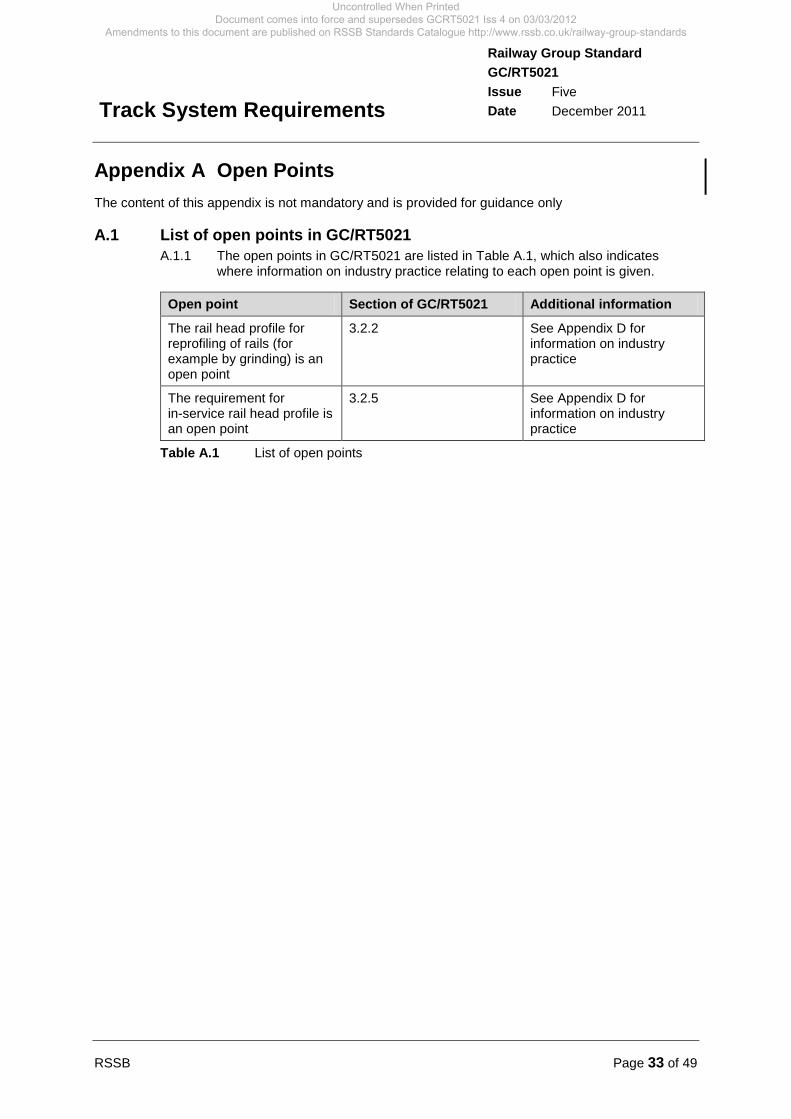
A.1 List of open points in GC/RT5021 A.1.1 The open points in GC/RT5021 are listed in Table A.1, which also indicates
where information on industry practice relating to each open point is given.
Open point Section of GC/RT5021 Additional information
The rail head profile for reprofiling of rails (for example by grinding) is an open point
3.2.2 See Appendix D for information on industry practice
The requirement for in-service rail head profile is an open point
3.2.5 See Appendix D for information on industry practice
Table A.1 List of open points
Uncontrolled When Printed Document comes into force and supersedes GCRT5021 Iss 4 on 03/03/2012
Amendments to this document are published on RSSB Standards Catalogue http://www.rssb.co.uk/railway-group-standards
Page 34 of 49 RSSB
Railway Group Standard GC/RT5021 Issue Five Date December 2011
Track System Requirements
Appendix B Guidance on Vertical Alignment The content of this appendix is not mandatory and is provided for guidance only
B.1 Track gradient design - factors to be considered B.1.1 The following factors should be taken into account when considering the design
of track gradients:
a) Existing geographical and railway infrastructure constraints.
b) The land available for construction.
c) Topography and site conditions.
d) Traffic type and speeds.
e) Parking brake capability of trains that may come to a stand on the gradient.
f) Stopping pattern and proximity of stations.
g) Routing and proximity of junctions.
h) Optimisation for tractive effort.
B.1.2 To avoid problems with available tractive effort, it is considered good practice that the design value for track gradient for freight traffic should be not steeper than 1 in 100.
B.1.3 The design of track gradients should take into account horizontal track curvature as horizontal curvature also increases the resistance to traction and braking.
Uncontrolled When Printed Document comes into force and supersedes GCRT5021 Iss 4 on 03/03/2012
Amendments to this document are published on RSSB Standards Catalogue http://www.rssb.co.uk/railway-group-standards
RSSB Page 35 of 49
Railway Group Standard GC/RT5021 Issue Five Date December 2011
Track System Requirements
Appendix C Explanatory Note: Requirements for Twist Faults The content of this appendix is not mandatory and is provided for guidance only
C.1 Twist faults and vehicle resistance to derailment C.1.1 A perceived 'incompatibility' between track twist limits and vehicle resistance to
derailment requirements is an issue that arises from time to time. It is the result of a misunderstanding.
C.1.2 GC/RT5021 requires that ’Twist faults (measured over 3 m) worse than 1 in 200 shall not be permitted to remain in the track. When twist faults are discovered they shall be repaired within a timescale commensurate with the risk of derailment, which in any case shall not be less stringent than the timescales set out in Table 2’. Table 2 requires closure of the line when a fault of 1 in 90 or worse is discovered.
C.1.3 GM/RT2141 requires vehicles to be tested for resistance to derailment on a twist fault. ’The test shall be such that it permits the measurement of the wheel load changes which are induced by the passage of the vehicle at very low speed over the track irregularity defined in Figure A.1. A test which simulates the behaviour by raising or lowering of the wheels of a stationary vehicle shall be acceptable. The off-loading of any wheel shall be such that, for any axle, the difference between the nominal wheel load (on level track) and the wheel load measured in the test does not exceed 60% of the nominal wheel load.’ The test is based on a long wavelength twist on which is superimposed a short wavelength track twist, giving a local twist of 1 in 150.
C.1.4 A direct comparison is sometimes made between the 1 in 90 in GC/RT5021 and the 1 in 150 in GM/RT2141. Such a comparison does not take into account that the 1 in 150 vehicle test is for wheel unloading of 60% (a larger unloading would be required for a derailment) and that the 1 in 90 track twist is an extreme fault, and a twist of worse than 1 in 200 is not permitted to remain in the track. In essence, the vehicle is tested for wheel unloading against a benchmark fault representing 'bad track', and not the most extreme fault it may encounter. There is no evidence that the two standards are incompatible.
C.1.5 RSSB Research Project T357 ‘Cost-effective reduction of derailment risk’ analysed the derailments where measures on both sides of the vehicle / track interface were relevant. This included slow speed derailments on twisted track which is the risk managed by the measures referred to above, and commented that additional contributory factors were required and ‘control of these derailments would be improved by earlier twist identification and better management of known derailment risks’. The recommendation stated (for all the identified risks): ‘Our analysis does not suggest that a change to mandatory standards would be effective in managing the residual derailment risk and therefore no action to amend RGS is proposed’. No evidence of incompatibility of standards was identified.
Uncontrolled When Printed Document comes into force and supersedes GCRT5021 Iss 4 on 03/03/2012
Amendments to this document are published on RSSB Standards Catalogue http://www.rssb.co.uk/railway-group-standards
Page 36 of 49 RSSB
Railway Group Standard GC/RT5021 Issue Five Date December 2011
Track System Requirements
Appendix D Open Points: Industry Practice Relating to Rail Profile
The content of this appendix is not mandatory and is provided for guidance only
D.1 Reprofiling of rails D.1.1 The requirement for reprofiling of rails (set out in section 3.2.2) has not yet been
developed and is an open point.
D.1.2 Pending the development of this measure, industry practice has been that the design rail head profile for reprofiling operations is applied in the knowledge of the relevant wheel profiles.
D.1.3 Industry practice is to carry out reprofiling of the longitudinal and transverse profile of rails to manage equivalent conicity.
D.1.4 This is an explicit open point in the Conventional Rail Infrastructure Technical Specification for Interoperability (CR INF TSI).
D.2 In-service rail head profile D.2.1 The requirement for in-service rail head profile (set out in section 3.2.5) has not
yet been developed and is an open point.
D.2.2 Pending the development of this measure, industry practice has been to manage the in-service shape of the rail head profile to mitigate specific problems (for example lipping).
D.2.3 If ride instability is reported on a track for rolling stock having wheelsets meeting the requirements of GM/RT2466, industry practice has been to conduct a joint investigation by the railway undertaking and the infrastructure manager to determine the reason.
D.2.4 This is an explicit open point in the Conventional Rail Infrastructure Technical Specification for Interoperability (CR INF TSI).
Uncontrolled When Printed Document comes into force and supersedes GCRT5021 Iss 4 on 03/03/2012
Amendments to this document are published on RSSB Standards Catalogue http://www.rssb.co.uk/railway-group-standards
RSSB Page 37 of 49
Railway Group Standard GC/RT5021 Issue Five Date December 2011
Track System Requirements
Appendix E Guidance on Identification of Points The content of this appendix is not mandatory and is provided for guidance only
E.1 Point identity E.1.1 Points with two or more ends that are required to be operated by the same
interlocking element should be identified by a common identity and a unique suffix for each end. Each signal box should have a convention for the allocation of suffixes. Where practicable, the suffixes for new layouts should increment alphabetically in the down direction. Where existing layouts are modified established conventions should be followed.
Uncontrolled When Printed Document comes into force and supersedes GCRT5021 Iss 4 on 03/03/2012
Amendments to this document are published on RSSB Standards Catalogue http://www.rssb.co.uk/railway-group-standards

Page 38 of 49 RSSB
Railway Group Standard GC/RT5021 Issue Five Date December 2011
Track System Requirements
Appendix F Free Wheel Passage and Flangeway in Switches The content of this appendix is not mandatory and is provided for guidance only
F.1 Free wheel passage and flangeway in switches F.1.1 Figure F.1 is provided to support the definition of free wheel passage and also
indicates the flangeway in switches.
Figure F.1 Free wheel passage and indication of flangeway in switches
Uncontrolled When Printed Document comes into force and supersedes GCRT5021 Iss 4 on 03/03/2012
Amendments to this document are published on RSSB Standards Catalogue http://www.rssb.co.uk/railway-group-standards
RSSB Page 39 of 49
Railway Group Standard GC/RT5021 Issue Five Date December 2011
Track System Requirements
Appendix G Explanatory Note: Requirements for Flangeway in Switches
The content of this appendix is not mandatory and is provided for guidance only
G.1 Flangeway in switches G.1.1 The requirements for flangeway in switches in GC/RT5021 were revised for issue
three of the document. This work was prompted by recommendations from the Potters Bar Formal Inquiry.
G.1.2 In closing out the recommendations from the Potters Bar Inquiry, RSSB made the following statement:
RSSB has reviewed requirements for flangeway clearances in points (taking into account emerging European requirements) in conjunction with Network Rail. The requirements for flangeway gaps in switches have been modified as follows:
a) The terminology used in the revised requirement for flangeway gaps in switches is consistent with the terminology used in the High Speed Infrastructure Technical Specification for Interoperability (HS INF TSI).
b) The requirements for maintenance of track gauge in switches have been strengthened.
c) The requirement for minimum flangeway for new designs of switches has been increased from 50 mm to 60 mm.
G.1.3 The measure requires that ‘A minimum flangeway gap of 100 mm shall be maintained at the toe of switches. A flangeway of not less than 60 mm, to provide a minimum free wheel passage of 1375 mm, shall be maintained elsewhere through the switch’. As this is a minimum dimension for any position through the switch it is considered not necessary to specify, in a Railway Group Standard, the depth and longitudinal position at which the flangeway dimensions are to be measured.
G.1.4 The impact assessment for GC/RT5021 issue three captures the changes made with respect to flangeways.
G.1.5 With respect to compliance with the requirements it was concluded at the time that the wider 60 mm flangeway could not be justified to be retrospective for older (113A) designs of switches because of the associated costs of re-design and that with appropriate maintenance and existing components the ‘historic’ designs of switches could be perpetuated. Note the more rigorous requirements for track gauge in S&C applies to all S&C.
G.1.6 It is worth noting that RSSB Research Project, T783 entitled, ‘Wheelset and switches and crossing compatibility investigation’ was carried out to support a GB specific case in the CR INF TSI, permitting the use of vertical S&C on the Conventional Rail Network. The research project investigated the compatibility between CEN56 S&C, including in-service limits, with both the ranges of Technical Specifications for Interoperability (TSI) compliant wheelsets and Railway Group Standard compliant wheelsets in-service in GB, and all permissible wear parameters. (CEN 56 S&C is Network Rail's term for 113A vertical S&C.)
Uncontrolled When Printed Document comes into force and supersedes GCRT5021 Iss 4 on 03/03/2012
Amendments to this document are published on RSSB Standards Catalogue http://www.rssb.co.uk/railway-group-standards
Page 40 of 49 RSSB
Railway Group Standard GC/RT5021 Issue Five Date December 2011
Track System Requirements
Appendix H Guidance on the use of Fixed Obtuse Crossings The content of this appendix is not mandatory and is provided for guidance only
H.1 Use of fixed obtuse crossings H.1.1 Inherent in the use of obtuse crossings in a S&C layout is the creation of a short
section of track where the guidance of a wheelset needs to be managed in a complex way. The limitations on the use of fixed obtuse crossings set out in 4.7.1.2 of this document, together with the requirements for check rail height set out in GC/RT5212 and the requirements for wheelsets set out in GM/RT2466, are intended to reduce the likelihood of a wheel flange passing on the wrong side of a point rail in an obtuse crossing.
H.1.2 There are recognised reliability and cost advantages in using fixed obtuse crossings rather than switch diamonds. The limits set out in 4.7.1.2 are based on past experience and are generally applicable. It is possible to design S&C layouts incorporating fixed obtuse crossings that do not meet these limits, but which still reduce the likelihood of a wheel flange passing on the wrong side of a point rail to an acceptable level. In particular, it is possible to employ a raised check rail to improve the guidance of the wheelset, as the requirement that the angle of the crossing is flatter than 1 in 8 is based on a crossing with a level check rail. However, the design of such S&C layouts is complex and needs to take account of a number of key track parameters, including crossing angles, track geometry (radius and cross level), check rail height and speed.
H.1.3 Research Project T560 ‘Safe limits of operation for shallow fixed obtuse crossings’ has provided a basis for the future design of S&C layouts incorporating obtuse crossings with angles flatter than 1 in 8 (See http://www.rssb.co.uk/SiteCollectionDocuments/pdf/reports/research/T560_rb_final.pdf).
H.1.4 The CR INF TSI (Commission Decision 2011/275/EU) sets a limit on the maximum unguided length of obtuse crossings by means of a reference case, rather than directly. (See http://eur-lex.europa.eu/LexUriServ/LexUriServ.do?uri=OJ:L:2011:126:0053:0120:EN:PDF)
H.1.5 Derogation 08/180/DGN allows for the use of a crossing angle of 1 in 8.69 for a particular track geometry and check rail configuration, based on Network Rail’s NR60 S&C.
H.1.6 These sources provide a basis for derogations from the requirements set out in 4.7.1.2 of this document.
Uncontrolled When Printed Document comes into force and supersedes GCRT5021 Iss 4 on 03/03/2012
Amendments to this document are published on RSSB Standards Catalogue http://www.rssb.co.uk/railway-group-standards
RSSB Page 41 of 49
Railway Group Standard GC/RT5021 Issue Five Date December 2011
Track System Requirements
Definitions Adjustment switch A scarf joint installed at the junction of continuous welded rail and jointed track to accommodate expansion of the continuous welded rail track. Adjustment switches are also used to protect track features such as S&C not designed for use in CWR and at the ends of some types of bridges. An adjustment switch is a particular type of expansion device and is also known as an expansion switch.
Ballast Nominally single–sized granular material of specified properties, placed on the blanket (where provided), subgrade or structure to provide vertical and lateral support to the sleepers or bearers.
Bearer A transverse beam that provides vertical and lateral support to S&C, usually cut from hardwood or softwood or made of steel or pre–stressed concrete.
Buffer stop An assembly provided at the end of a terminal track to arrest an overrunning train, designed to take the impact of the train at buffer or coupling height.
Cant For the purposes of this document, cant is expressed as the design difference in level, measured in millimetres, between rail head centres (generally taken to be 1500 mm) of a curved track.
Cant deficiency The difference between actual cant and the theoretical cant that would have to be applied to maintain the resultant of the weight of the vehicle and the effect of centrifugal force, at a nominated speed, such that it is perpendicular to the plane of the rails. For the purposes of this document, cant deficiency is always the cant deficiency at the rail head, not that experienced within the body of a vehicle.
Cant gradient The rate at which cant changes in a specific length.
Catch point Points provided for derailing a vehicle running back on a gradient in the wrong direction.
Check gauge The distance between the running edge of a running rail and the bearing face of the opposite check rail, measured at right angles to the rails in a plane 14 mm below their top surface.
Check rail A rail or special section provided alongside a running rail at a specified dimension inside gauge to provide a flangeway, to give guidance to wheelsets by restricting lateral movement of the wheels.
Clamp lock A point operating mechanism which locks the points by directly clamping the closed switch rail to the stock rail.
Uncontrolled When Printed Document comes into force and supersedes GCRT5021 Iss 4 on 03/03/2012
Amendments to this document are published on RSSB Standards Catalogue http://www.rssb.co.uk/railway-group-standards
Page 42 of 49 RSSB
Railway Group Standard GC/RT5021 Issue Five Date December 2011
Track System Requirements
Clothoid spiral (transition curve) A transition curve between a straight and a curve where the curvature (the reciprocal of the radius) is proportional to the distance along the curve from its tangent point with the straight.
Crossing A cast or fabricated portion of the track layout which enables the rails of the two tracks to cross each other, while still providing support and guidance for smooth passage of the vehicle’s wheels.
Crossing vee Two rails which are joined at an acute angle.
Curvature The reciprocal of the radius of a curve.
Cyclic top Cyclic top is the term used to describe a series of regular dips in the vertical alignment of one or both rails. They may not always be apparent visually because other top irregularities may obscure the cyclic pattern. Cyclic irregularities in track geometry have the potential, when combined with a vehicle’s natural vertical response for a given speed and load, to cause a derailment.
CWR Abbreviation for ‘continuous welded rail’:
a) Rails installed in the track that have been welded together to form a single rail greater than a nominal 55 m in length.
b) Track constructed with continuous welded rail.
Derailer A device attached to a rail that will, when in its effective position, cause the derailment of a vehicle. It is used to guard against unauthorised movements.
Design mass under normal payload Design mass of the vehicle in working order plus the normal design payload. BS EN 15663:2009 specifies reference states meeting this definition.
Detection A mechanism that proves and provides an output to indicate the actual position of a point end (normal or reverse), and that where fitted, the facing point lock is fully engaged.
Dynamic sleeper support stiffness The peak load divided by the peak deflection of the underside of a rail seat area of an unclipped sleeper subjected to an approximately sinusoidal pulse load at each railseat; the pulse load being representative in magnitude and duration of the passage of a heavy axle load at high speed, typically 20 t at 100 mph. A falling weight deflectometer can be used to measure dynamic sleeper support stiffness directly.
Enhanced permissible speed The permitted speed (higher than the permissible speed) over a section of line which applies to a specific type of train operating at cant deficiencies in excess of those permitted at the permissible speed. Enhanced permissible speeds are detailed in the Sectional Appendix. There may be more than one enhanced permissible speed applicable to a given section of line.
Uncontrolled When Printed Document comes into force and supersedes GCRT5021 Iss 4 on 03/03/2012
Amendments to this document are published on RSSB Standards Catalogue http://www.rssb.co.uk/railway-group-standards
RSSB Page 43 of 49
Railway Group Standard GC/RT5021 Issue Five Date December 2011
Track System Requirements
Equivalent conicity Parameter for characterisation of the wheel-rail contact. For a given wheelset running on given track it equals the tangent of the taper angle of a tapered profile wheelset whose transverse movement has the same wavelength of kinematic yaw as the wheelset under consideration.
External command An instruction sent to the point operating mechanism by the interlocking to move the point ends to the normal or reverse position.
Facing point lock A mechanical means of physically locking points in the normal or reverse position so that they cannot be moved other than in response to an external command or manual operation. The lock may be provided independently or incorporated into a point operating mechanism.
Flange The projecting rim of a rail vehicle wheel.
Flangeway The gap provided to permit the passage of the wheel flanges of rail vehicles, for example between a check rail and a running rail. See Appendix F for a diagram depicting the flangeway.
Free wheel passage The dimension provided to allow a wheelset to pass through a set of switches or a swing nose crossing, without undesirable contact being made with the wheel flange back and the open switch rail or crossing. In switches this dimension is taken from the back edge of an open switch rail and the running edge of the closed switch rail. See Appendix F for a diagram depicting the free wheel passage.
Gauge point The point of intersection of the gauge corner radius and the flat side of the rail head. For 60 E 1 and BS 113A rails this is nominally 14.5 mm below the top of the rail head, measured parallel to the vertical axis of the rail.
Head width The width of the rail head measured perpendicular to the vertical axis of the rail at the gauge point.
Jointed track A method of track construction where rails are joined together by fishplates, with an expansion gap between rail ends.
Level crossing An intersection at the same level of a road, footpath or bridleway and one or more railway tracks.
Loaded track gauge The track gauge measured in a loaded condition, representing the track gauge under the passage of trains. See also ‘track gauge’.
Uncontrolled When Printed Document comes into force and supersedes GCRT5021 Iss 4 on 03/03/2012
Amendments to this document are published on RSSB Standards Catalogue http://www.rssb.co.uk/railway-group-standards
Page 44 of 49 RSSB
Railway Group Standard GC/RT5021 Issue Five Date December 2011
Track System Requirements
Lock stretcher bar A bar that connects together the two switch rails of a set of switches and which incorporates or is connected to a bolt which locks the switch rails in the normal or reverse position.
Longitudinal timber A timber parallel to and supporting a running rail.
Loss of section The reduction in the cross sectional area of a rail, compared to that when new.
Misalignment Deformation or displacement of a rail or track from its designed alignment.
Negative cant Cant is negative when the inner rail of a curve track is raised above the level of the outer rail. Also known as adverse cant.
New trackbed Trackbed layers placed where there was previously no track. Compare with ‘Renewal (of trackbed)’.
Non-ballasted track Track that is not supported on ballast, including concrete slab track, track supported on longitudinal timbers and directly fastened track on bridges.
Normal and reverse The two defined positions for worked points that are set by the signalling system. The normal and reverse position of each point end is determined by the configuration of the signalling arrangement.
Obtuse crossing An assembly to permit the passage of wheel flanges where two rails intersect at an obtuse angle.
Open point An open point is a technical aspect corresponding to the essential requirements which has not been explicitly covered in a Technical Specification for Interoperability (TSI).
Out of use points Points not in use, either newly laid in, awaiting commissioning, temporarily decommissioned or awaiting removal.
Overspeed The amount by which the actual speed of a train could exceed the enhanced permissible speed for any reason.
Permissible speed The maximum permitted speed over a section of line that applies to trains when not operating at an enhanced permissible speed. Permissible speeds are detailed in the Sectional Appendix.
Plain line Track not incorporating S&C. The term ‘plain line’ therefore excludes the through route of S&C.
Uncontrolled When Printed Document comes into force and supersedes GCRT5021 Iss 4 on 03/03/2012
Amendments to this document are published on RSSB Standards Catalogue http://www.rssb.co.uk/railway-group-standards

RSSB Page 45 of 49
Railway Group Standard GC/RT5021 Issue Five Date December 2011
Track System Requirements
Point end An item with a movable track component forming one element in a set of points. For the purpose of this document, the term includes a set of switches, one half of a set of switch diamonds, a swing nose crossing, all forms of trap points, a derailer or a scotch block.
Point operating mechanism Equipment provided to drive a point end between the normal and reverse positions, using powered or mechanical means.
Points A group of one or more point ends which are operated together by a common external command and may be aligned to one of two positions, normal or reverse, according to the train movement required.
Primary drive The point operating mechanism positioned at the toe of points.
Rail fastenings Any device used to secure running rails into chairs or baseplates or directly to sleepers, bearers or other rail supports.
Rate of change of cant The rate at which a vehicle experiences the change in design cant measured in millimetres per second.
Rate of change of cant deficiency The rate at which a vehicle experiences the change in design cant deficiency measured in millimetres per second.
Renewal (of trackbed) The replacement of existing trackbed layers or provision of new trackbed layers. For the purposes of this document, renewal includes remodelling, relaying, track lowering and reballasting.
The replacement of former trackbed layers or provision of new trackbed layers when track that has been removed is subsequently re–instated is classed as a ‘renewal’ for the purposes of this document, not a ‘new trackbed’.
Reverse curve Two abutting curves of opposite flexure or hand.
Running line A line as shown in Table A of the Sectional Appendix.
Scotch block A device attached to a rail that will, when in its effective position, prevent the movement of stationary vehicles.
Sidewear The loss of head width on the running edge of the rail measured perpendicular to the vertical axis of the rail at the gauge point.
Uncontrolled When Printed Document comes into force and supersedes GCRT5021 Iss 4 on 03/03/2012
Amendments to this document are published on RSSB Standards Catalogue http://www.rssb.co.uk/railway-group-standards
Page 46 of 49 RSSB
Railway Group Standard GC/RT5021 Issue Five Date December 2011
Track System Requirements
Sleeper A transverse beam that provides vertical and lateral support to plain line running rails, rail fastenings and where appropriate check rails, guard rails, conductor rails and ancillary operating equipment.
Standard deviation Standard deviation is a universally used scientific measure of the variation of a random process. Track profiles have been found to have sufficiently similar statistical properties to random processes to enable a measure of the magnitude of track irregularities to be obtained from the standard deviation of the vertical and horizontal profile data. This form of analysis provides track quality indices.
Stretcher bar A bar that connects together the two switch rails of a set of switches to maintain flangeways.
Structure Something built to support or retain a load. For the purposes of this document, the term includes bridges, viaducts, tunnels and culverts, but excludes earthworks.
Supplementary detection One or more additional point detectors provided to prove the position of switch rails at a distance from the switch toes.
Supplementary drive A drive provided where necessary in addition to the primary drive to ensure that switch rails or a swing nose crossing are correctly aligned and provide an adequate flangeway throughout their length. For the purpose of this document, the term ‘supplementary drive’ includes back drives and supplementary point operating mechanisms.
Swing nose crossing A common crossing in which the crossing vee can move laterally to close the flangeway to one or other of the wing rails to provide continuous support to wheelsets. This type of crossing does not require the use of check rails. A swing nose crossing counts as one point end.
Switch diamonds A set of switch diamonds consists of two obtuse crossings in which the obtuse point rails are replaced by switch rails and a check rail is not required. A set of switch diamonds counts as two point ends.
Switches A set of switches consists of two fixed stock rails with their two associated moveable switch rails. A set of switches counts as one point end.
S&C Abbreviation for switch and crossing. A track layout incorporating switches and / or crossings that allows one track to cross another or diverge from or merge with another.
Switch toe The end of the switch rail that is traversed first by a vehicle negotiating the switch in the facing direction.
Uncontrolled When Printed Document comes into force and supersedes GCRT5021 Iss 4 on 03/03/2012
Amendments to this document are published on RSSB Standards Catalogue http://www.rssb.co.uk/railway-group-standards

RSSB Page 47 of 49
Railway Group Standard GC/RT5021 Issue Five Date December 2011
Track System Requirements
Through route and turnout route in S&C In most S&C the through route is the one that carries the majority of traffic and is usually the route through which permissible speed remains unchanged. The turnout route is typically the one that carries less traffic and usually has a permissible speed substantially lower than that of the through route.
Tight joint Non-insulated connection of two rails by means of specially drilled fishplates and rail fastening devices but without an expansion gap between the rail ends.
Track fault A hazardous track geometry condition requiring remedial attention. In this document, the conditions covered by this term include twist (unintentional or non-compliant variation in cross level), track gauge, vertical profile (including cyclic top) and lateral alignment.
Track gauge The distance between the running edges of the rails in a track, measured without load at right angles to the running edges of the rails in a plane 14 mm below their top surface. See also ‘loaded track gauge’.
Track system The assemblage of rails, rail supports, rail fastenings, sleepers, timbers or bearers and ballast or other forms of support, acting together to provide guidance and support for rail vehicles.
Trackbed A general term referring to the ballast, blanket and subgrade.
Trackbed layers A general term referring to all layers placed between the subgrade and the underside of sleepers or bearers.
Train operated points Points which are designed for use in running lines with facing movements in the normal position only. They are operated by the passage of trains in the trailing reverse direction. They are restored to the normal position by the point operating mechanism after the passage of each train (compare with ‘worked points’). ‘Hydro-pneumatic self restored points’ are a type of train operated points.
Transition curve A curve between a straight and a curve, or between curves of different radius, along which the radius changes in a regular (though not necessarily uniform) manner.
Trap points Facing points provided at an exit from a siding or converging line to de–rail an unauthorised movement, thus protecting the adjacent running line.
Twist fault A difference in cross-levels over a short distance (usually measured over 3 m) that is greater than a predetermined amount.
Twist rail A length of rail that changes in inclination from generally 1 in 20 to generally vertical.
Uncontrolled When Printed Document comes into force and supersedes GCRT5021 Iss 4 on 03/03/2012
Amendments to this document are published on RSSB Standards Catalogue http://www.rssb.co.uk/railway-group-standards

Page 48 of 49 RSSB
Railway Group Standard GC/RT5021 Issue Five Date December 2011
Track System Requirements
Underfoot gall Wear of the underside of a rail foot caused by chairs or baseplates abrading the rail.
Unworked points Points not controlled by the signalling system, other than train operated points. Hand points, runaway catch points and spring operated points (usually only used as trap or catch points) are examples of unworked points.
Vertical curve A curve joining two track gradients in their vertical alignment.
Worked points Points which are controlled by the signalling system (compare with ‘train operated points’).
Uncontrolled When Printed Document comes into force and supersedes GCRT5021 Iss 4 on 03/03/2012
Amendments to this document are published on RSSB Standards Catalogue http://www.rssb.co.uk/railway-group-standards
RSSB Page 49 of 49
Railway Group Standard GC/RT5021 Issue Five Date December 2011
Track System Requirements
References The Catalogue of Railway Group Standards and the Railway Group Standards DVD give the current issue number and status of documents published by RSSB. This information is also available from www.rgsonline.co.uk.
Documents referenced in the text RGSC 01 Railway Group Standards Code RGSC 02 The Standards Manual Railway Group Standards GC/RT5033 Terminal Tracks – Requirements for Buffer Stops,
Arresting Devices and End Impact Walls GC/RT5212 Requirements for Defining and Maintaining Clearances GE/RT8012 Controlling the Speed of Tilting Trains Through Curves GI/RT7016 Interface between Station Platforms, Track and Trains GK/RT0028 Infrastructure Based Train Detection Interface
Requirements GK/RT0039 Semaphore and Mechanical Signalling GM/RT2141 Resistance of Railway Vehicles to Derailment and
Roll-Over GM/RT2142 Resistance of Railway Vehicles to Roll-Over in Gales GM/RT2466 Railway Wheelsets GM/TT0088 Permissible Track Forces for Railway Vehicles RSSB documents GC/RC5521 Calculation of Enhanced Permissible Speeds for Tilting
Trains Other references BS EN 13674-1:2003+A1:2007 Railway Applications – Track Rail – Part 1: Vignole railway
rails 46 kg/m and above BS EN 15663:2009 Railway applications. Definition of vehicle reference
masses CR INF TSI Conventional Rail Infrastructure TSI, Decision
2011/275/EU (OJ L126, 14.5.2911, p1) HS INF TSI High Speed Infrastructure TSI, Decision 2008/217/EC
(OJ L77, 19.3.2008, p1) T357 Cost-effective reduction of derailment risk, RSSB
Research Project (January 2006) T560 Safe limits of operation for shallow fixed obtuse crossings
(September 2007) T783 Wheelset and switches and crossing compatibility
investigation, RSSB Research Project (January 2009) Potters Bar Formal Inquiry Recommendations Report
(March 2005)
Uncontrolled When Printed Document comes into force and supersedes GCRT5021 Iss 4 on 03/03/2012
Amendments to this document are published on RSSB Standards Catalogue http://www.rssb.co.uk/railway-group-standards